1
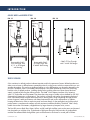
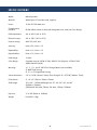
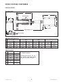
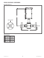
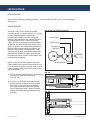
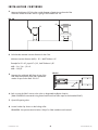
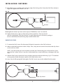
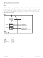
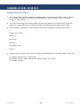
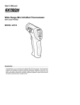
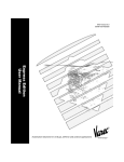
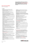
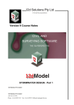
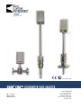
PTB 04 ATEX 1027
KAM® CHA™ COLORIMETER/HAZE ANALYZER
API COMPLIANT
User Manual
TEL +1 713 784 0000
FAX +1 713 784 0001
Email [email protected]
CHAMANUAL-0413
KAM CONTROLS, INC.
3939 Ann Arbor Drive
Houston, Texas 77063 USA
www.KAM.com
TABLE OF CONTENTS
SECTIONTITLEPAGE
1 Introduction 2
•Available Models and Mounting Options 2
•Theory of Operation
2
•Features 3
•Applications
3
2 Specifications
•Specifications
•Dimensional Drawings 4
4
5
3 Installation 7
•Main Line 7
•Removal 9
•Wiring
10
•4-20 mA Outputs 11
4Maintenance12
5 Communications Interface
13
6
Additional Drawings
14
CAUTION:
When installing the CHA™ sensor in a pipeline containing petroleum products,
petro-chemicals, waste waters with the presence of pressure & temperature, and high-pressure
steam refer to the Pipeline Operators’ “Health, Safety and Environmental Policy Procedures” to
ensure safe installation.
KAM CONTROLS, INC. reserves the right to make changes to this document without notice.
CHAMANUAL 0413
1
KAM CONTROLS, INC.
INTRODUCTION
AVAILABLE MODELS and MOUNTING OPTIONS
FIG. 1-1
Fullopening
ball
valve
Rectractable CHA™
on a main pipe, with
2", 3", or 4" flanged
seal housing
FIG. 1-2
FIG. 1-3
Fullopening
ball
valve
Rectractable CHA™
on a main pipe, with
2" MNPT seal housing
CHA™ FT Flow Through
with 1" ANSI 150 flanges
THEORY OF OPERATION
Color variations in refined products indicate impurities and/or the presence of water. Refined products are
often prone to haze or diffused water contamination due to cooling towers which use water and in turn can
saturate the product. This can be a significant liability as color differentiation can be easily detected by the
end user. The KAM® CHA™ Colorimeter/Haze Analyzer is the ideal quantitative solution for monitoring
both the color of refined products, including dyed product, and the presence of haze (trace/dissolved
water) in pipelines following the refining process. The KAM® CHA™ detects interface color variations
within 1%, and unlike most colorimeters can detect the entire range of visible color as defined by CIE 1931
(International Commission on Illumination). The simplicity of design and quality of engineering employed
in the Colorimeter/Haze Analyzer mean there are no moving parts. Using long-lasting LED light sources
ensures long-term, stable performance with limited maintenance and power requirements. In addition,
locating the electronics within an explosion-proof enclosure directly on the atmospheric end of the optical
probe creates a complete and compact unit with maximum installation flexibility. The KAM® CHA™ easily
installs where other colorimeters, weighed down by large electronics/computer units, cannot. The five LED sources (Red, Blue, Green, Yellow, and IR) send light via fiber optics to the sensor end inserted
into the pipeline or analyzer loop. These beams of light pass through a 25mm window of pipeline fluids
and then are reflected back through fiber optics to the electronics enclosure for a total path of 50mm.
CHAMANUAL 0413
2
KAM CONTROLS, INC.
INTRODUCTION CONTINUED
KAM uses four LED's for color determination to increase the accuracy over three-color (RGB) models.
The fifth (IR) LED provides haze detection. The disparity in light output versus light reflected back is then
converted into an electronic or optical signature which is amplified and sent to the computer. The computer
in turn utilizes a mathematical formula to determine the exact color and haze (turbidity) of the fluid in the
pipeline. Final color measurement from the KAM® CHA™ can be expressed as haze plus three color (X,
Y, Z, CIE 1931) or in several other industry-standard color scales including, Saybolt, Platinum and Cobalt,
and ASTM 1500 (see Specifications, Section 2).
The computer automatically adjusts for electronic noise and any LED fluctuations. Because the absorption
rates of the different colored fluids vary resulting in different signal strengths, the computer also
automatically adjusts the amplification or gain accordingly.
Measurement is fully automatic without the need for operator intervention or supervision. The output signal
can be sent to the SCADA, PLC’s, or to a Central Control Room for logging or display on chart recorders
or monitors.
The KAM® CHA™ probe can be installed in an analyzer loop or in the main line, and because it’s easily
mounted through a full-opening ball valve, you can insert or retract the probe without having to ever drain
the pipe.
FEATURES
•
•
•
•
•
•
User friendly
Low power
Explosion proof
Low maintenance
Compact format includes requisite electronics
Long-lasting LED light sources
APPLICATIONS
• Batching
• Interface
• Production
• Transmix/regrade reduction
• Quality control in refined products including dyed and undyed motor and aviation gasoline, jet
propulsion fuels,
naphthas and kerosine
• Quality control in pharmaceutical white oils and petroleum waxes
• Brine detection in LPG transfer from storage caverns
CHAMANUAL 0413
3
KAM CONTROLS, INC.
SPECIFICATIONS
Media:
Refined products
Material:
Wetted parts–316 stainless steel, sapphire
Power: 12–24 VDC 20 Watts max
Communication
Interface:
RS-485 reflects values for Haze plus designated color scale (see Color Range)
Fluid temperature:
-40º to 200ºF (-40º to 93ºC)
Electronics temp.: -22º to 185ºF (-30º to 85ºC)
Pressure ratings: ANSI 150, 300, 600
Accuracy:
Haze ± 5%, Color ± 1%
Repeatability: Haze ± 1%, Color ± 1%
Reproducibility:
Haze ± 1%, Color ± 1%
Haze Range: 0-100%
Color Range: Complete range of: ASTM D 1500; ASTM D 156 (Saybolt); ASTM D 1209
(APHA Platinum-Cobalt)
Mounting:
¾", 1", 1½", and 2" FNPT Flow Through (Metric sizes available)
2" MNPT Seal Housing
2", 3", or 4" Flanged Seal Housing
Sensor Dimensions:
3.5" x 1.25"Ø (90mm x 32mm), Flow through 5.8" x 2.75"Ø (148mm x 70mm)
EX enclosure: 3" x 6" x 3" (76mm x 152mm x 76mm)
Shaft length:
12" to 60" – Off-the-shelf lengths are 12", 24", 36", 48", and 60"
(305mm to 1524mm)
(Off-the-shelf 609.6mm, 762mm, 914.4mm, 1219mm, 1524mm)
Pipe size:
¾" to 48" (20mm to 1200mm)
Weight: from 20 lbs. (9kg)
CHAMANUAL 0413
4
KAM CONTROLS, INC.
SPECIFICATIONS CONTINUED
DIMENSIONAL DRAWINGS
FIG. 2-1CHA™ SENSOR
SL
C
A
Seal Housing
B
D
¾" FNPT
E
F
Shaft Length ± .5"
Sensor Profile
TABLE 2-2 FLANGE SIZE AND CLASS (SL)
150
300
900
600
"
INCHES
MM
INCHES
MM
INCHES
MM
INCHES
MM
2
8.40
213
8.50
216
8.90
226
9.40
240
3
8.60
218
8.75
222
9.15
232
9.40
240
4
8.60
218
8.90
226
9.40
240
9.65
245
TABLE 2-3 DIMENSIONS
INCHES
MM
A
1.25
32
B
3.5
90
C
7.25
184
D
4.7
119
E
.47
12
F
1
25
CHAMANUAL 0413
Shaft Lengths are available in .5"
(12.7mm) increments.
Standard sizes are 24", 30", 36",
48", and 60". (609.6mm, 762mm,
914.4mm, 1219mm, 1524mm)
5
KAM CONTROLS, INC.
SPECIFICATIONS CONTINUED
FIG. 2-4 FLOW THROUGH CHA™
D
C
A
ANSI FLANGES
B
TABLE 2-5 DIMENSIONS
INCHES
MM
A
11.8
299
B
11
279
C
7.25
184
D
4.7
119
CHAMANUAL 0413
6
KAM CONTROLS, INC.
INSTALLATION
PRIOR TO INSTALLATION
Remove all the protective packaging materials , and ensure that the CHA™ sensor was not damaged
during transit.
MAIN LINE INSTALLATION
The KAM CHA™ sensor should be installed
according to FIG. 3-1, ideally at the 3 or 9 o'clock
position within the pipeline. Installing the
instrument horizontally prevents the long-term
buildup of any sediment on the sapphire windows.
A full-opening ball valve is used to isolate the
CHA™ sensor from the pipeline during installation
or removal. The seal housing of the CHA™ sensor
allows the probe to be inserted and removed from
the pipe under pressure and flow conditions. It is
the user’s responsibility to ensure that the CHA™
sensor be placed at the most representative point
within the flow profile. The CHA™ sensor should
be inserted so that the window of the probe is fully
located within the pipeline.
®
FIG. 3-1 KAM® CHA™ INSTALLED ON A MAIN PIPE
Locking Collar
Seal Housing
Full-opening
Ball Valve
Socket Cap Screw
NOTE: Line pressure must be below 100 psi for
CHA installation and removal. Pressure above 100
psi could cause the probe to forcibly move outward from the pipeline risking bodily injury and/or damage to the probe.
1. Prior to mounting verify that the tip of the sensor
is all the way inside the seal housing.
(FIG. 3-2,3-3)
2. If sensor is not fully enclosed inside the seal
housing, pull the shaft back until the probe is
all the way in the seal housing and tighten
the socket cap screws on the locking collar.
This will prevent the CHA™ shaft from sliding
and the probe from getting damaged during
mounting.
CHAMANUAL 0413
FIG. 3-2
FIG. 3-3
7
KAM CONTROLS, INC.
INSTALLATION CONTINUED
3. Measure the distance (D1) from the outside diameter of main pipe to the end of the
connection where the CHA™ sensor is going to be installed. FIG. 3-4.
FIG. 3-4
D1
D1
4. Calculate the minimum insertion distance for the CHA.
Minimum insertion distance (MID) = D1 + Wall Thickness + 2"
Example for D1=16", pipe WT =1/4", Seal Thickness=1/8":
MID = 16 + 1/4 + 1/8 + 2
MID = 18 3/8"
FIG. 3-5
5. Measure the calculated MID from the top of the
seal clamp and place a mark with a permanent
marker or tape on the Shaft. FIG. 3-5.
MID
6. Bolt or screw the CHA™ sensor to the valve or designated installation location.
(KAM CONTROLS recommends using thread sealant and not Teflon tape for the threaded CHA™).
7. Open full opening valve.
8. Loosen Socket Cap Screws on the locking collar.
REMINDER: Line pressure must be below 100 psi for CHA installation and removal.
CHAMANUAL 0413
8
KAM CONTROLS, INC.
INSTALLATION CONTINUED
9. Push CHA™ sensor in until the mark is at the top edge of the locking collar. Ensure that CHA™ flow indicator is
aligned with pipeline flow direction. FIG. 3-6.
FIG. 3-6
Mark
Hex Nuts
10. Re-tighten the Socket Cap Screws with a torque of 750-800 lb-in or 62.5 to 66.6 lb-ft.
11. Tighten the Hex Nuts on the top of the Locking Collar one half turn. These nuts should
never be over-tightened. Their major function is to apply light pressure on the chevron packing to
ensure a seal between the seal housing body and the insertion shaft.
REMOVING THE CHA™ SENSOR
1.
To remove the CHA™ sensor, first disconnect all electrical connections to the CHA™ enclosure.
2. Make sure that the line pressure is below 100 psi. Then, slowly and with caution loosen the Socket Cap Screws
on the Lock Down Collar.
NOTE: Once the Socket Cap Screws have been loosened, the CHA shaft may push out from the line. If pressure in the line is above 100 psi, it may do so with enough force to cause bodily injury or damage to the instrument.
3. Slide the CHA™ sensor upward until it stops and the probe rests inside the seal housing. Fig. 3-7. The mechanical stop prevents further movement or ejection of the shaft and/or sensor.
4. Next, close the Full-opening Ball Valve tightly. The CHA™ sensor may now be unbolted from the system.
FIG. 3-7
Mechanical
Stop
Socket Cap Screws
CHAMANUAL 0413
9
KAM CONTROLS, INC.
INSTALLATION CONTINUED
WIRING
FIG. 3-8
ASTM
SAYBOLT
Pt/Co
HAZE
1
2
3
4
J5
LOOP1
J7
LOOP2
JUMPERS TO SELECT SIGNAL/
SCALE FOR 4-20 mA OUTPUTS
KAM CHA
3939 Ann Arbor Drive
Houston, Texas
77063, USA
+1 713 784 0000
www.KAM.com
RTN
485 +
Loop1
IN
485 -
Loop1
IN
GND
Loop2
(–)
RTN
Vin
(+)
Loop2
Vin
Rev 2.01
12/2012
Made in USA
POWER
CONNECTIONS
COMMUNICATION
INTERFACE
4-20 mA
CONNECTIONS
POWER
COMMUNICATION INTERFACE
12 or 24 VDC (5 watts max)
RS–485
CAUTION: When electronics enclosure is open, be
extremely careful to avoid any contact with interior fiber
optic connections. Failure to do so could result in the
CHA malfunctioning.
CHAMANUAL 0413
10
KAM CONTROLS, INC.
INSTALLATION CONTINUED
OUTPUTS
LOOP1 and LOOP2 can output signals for any 2 of 4 different scales: ASTM, Saybolt, Platinum/Cobalt, and Haze.
To select which signal or scale is associated with which 4-20 mA output, insert a jumper across the pins next to the
label for the desired scale. See Fig. 3-9. Place ONE jumper in J5 and one in J7 to select two scales total. Inserting
more than one jumper for either LOOP or inserting the jumper across two inputs or two outputs will result in the
malfunctioning of the instrument.
FIG. 3-9
ASTM
SAYBOLT
Pt/Co
HAZE
SCALE
1
2
3
4
J5
LOOP1
J7
LOOP2
JUMPER INPUT
JUMPER OUTPUT
PROPER JUMPER
PLACEMENT ACROSS INPUT
AND OUTPUT
KAM CHA
COLOR SCALE RANGES
3939 Ann Arbor Drive
SCALE Houston, Texas
77063, USA
ASTM +1 713 784
0000
Saybolt
www.KAM.com
Platinum/Cobalt
Haze RANGE
.5 to 8
-30 to 16
0 to 500
0 to 100
RTN
485 +
Loop1
IN
485 -
Loop1
IN
GND
Loop2
Rev 2.01
12/2012
Made in USA
CHAMANUAL 0413
11
KAM CONTROLS, INC.
MAINTENANCE
CLEANING AND INSPECTION
Under normal operation, the KAM CHA should not require cleaning, unless pipeline usage is limited to a small
number of products. Gasoline products or jet fuel in the pipeline will clean the CHA without removal.
To remove any oil residues for visual inspection use a clean cloth with oil solvent or part washer.
Preferred solvents include, any petroleum solvent such as mineral spirits, xylene, toluene, gasoline, or diesel. Do
not use WD40 or other chemicals.
If you have a question regarding cleaning solvents, please contact KAM CONTROLS directly at +1 713 7840000, or email: [email protected]
CHAMANUAL 0413
12
KAM CONTROLS, INC.
COMMUNICATIONS INTERFACE
HYPERTERMINAL PROMPTS FOR RS-485 CONNECTION
1.
Once Hyperterminal software is launched, a dialogue window will prompt you to "Enter a name and choose
an icon for the connection." Name the connection whatever you want, for example "CHA 1." Ignore the
choose icon option. Hit OK.
2. The "Connect To" dialogue box will now appear. On the last line where it says "Connect using" choose the
name of the communication port connected to the CHA via RS-485 from the drop-down menu. Hit OK.
3. The "Port Settings" dialogue box will now appear. Enter the following values from the drop-down menu:
Bits per second: 1200
Data bits: 7
Parity: Even
Stop bits: 2
Flow control: None
Hit OK.
4. A blank screen with prompt will now open. To display CHA readings type one of three prompts, E1, E2, or E3.
E1: Displays values for Z, Y, Z, and T (haze)
E2: Displays values for ASTM, Saybolt, PtCo (Platinum Cobalt), and T (haze)
E3: Displays all values
CHAMANUAL 0413
13
KAM CONTROLS, INC.