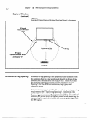
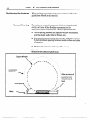
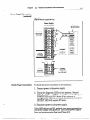
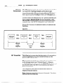
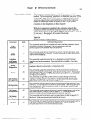
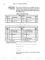
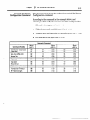
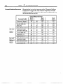
1
important User
information
Solid-state equipment has operational characteristics
differing
from those of electromechanical
equipment. “Application
Considerations
for Solid-State Controls” (Publication SGI-1.1)
describes some important differences between solid-state
equipment and hard wired electromechanical
devices. Because
of this difference, and also because of the wide variety of uses for
solid-state equipment, all persons responsible for applying this
equipment must satisfy themselves that each intended
application of this equipment is acceptable.
In no event will the Allen-Bradley Company be responsible or
liable for indirect or consequential damages resulting from the
use or application of this equipment.
The examples and diagrams in this manual are included solely
for illustrative purposes. Because of the many variables and
requirements associated with any particular installation,
the
Allen-Bradley Company cannot assume responsibility
or
liability for actual use based on the examples and diagrams.
No patent liability is assumed by the Allen-Bradley Company
with respect to use of information, circuits, equipment, or
software described in this manual.
Reproduction of the contents of this manual, in whole or in part,
without written permission of the Allen-Bradley
Company is
prohibited.
01991 Allen-Bradley
Company, Inc.
Table
of Contents
Chapter
1
Page
Title
Using this Manual
Chapter Objectives . . . _. . . _ . . . . _. . . . . . . . . . . . . . . _. .
Manual Overview . . . . . . _. _ . . . . . . . . . . _ . . __ . . . . . . .
Manual Chapter Overview . . _. . . . . . _. . . . . . . . . . . . . .
Intended Audience (s) . . . . . . . . . . . . . . . . . . . . . . _ . . . . _
Definition of Major Terms . . . . _. . . . . . . . . . . . . . . . . . .
.............................
Related Publications
2
Introduction
1-l
l-1
l-2
l-3
l-3
l-4
to the RF/D System
...............................
ChapterObjectives
Description of the Intelligent Antenna .............
............................
HardwareFeatures
RFID System Components .........................
RFTags ......................................
RFID System Host ..............................
Power Supply .................................
Object Detect Device ..........................
..............................
Antenna Operation
Tag Transactions ..............................
.......................
Typical “Read” Application
RFID Site Evaluation ..............................
2-l
2-l
2-2
2-4
2-4
2-5
2-5
2-5
2-5
2-6
2-7
2-8
Host Options and Communication Requirements
Chapter Objectives ...............................
....................................
HostOptions
Host Communication Protocols ....................
................................
ASCllProtocol
DFl Protocol ..................................
...................
Hardware Interface to Antenna
Communication Interface Parameters ...........
Hardware Configurable Parameters .............
...........
Programmable Interface Parameters
4
3-1
3-l
3-2
3-2
3-2
3-3
3-3
3-3
3-3
RF/D Component Set- up Guidelines
Chapter Objectives ...............................
Component Set-up Overview ......................
Capture Window
................................
Antenna-to-Tag Spacing ..........................
4-1
4-l
4-1
4-2
Table of Con tents
2
Chapter
4
Title
RF/D Component Set-up Guidelines (continued)
Tag-to-Tag Spacing ..............................
Programmable Tag Spacing ....................
Read/write Tag Spacing .......................
Positioning the Antenna
.........................
Recessed Mounting
...........................
Effects of Metallic Surfaces ....................
Minimizing the Effects of Metallic Surfaces ......
Defining the Capture Window Boundaries .........
Tag-to-Antenna Orientation ......................
Moving Tag Speed Limitations ....................
Testing Tag Transactions .........................
Positioning the Object Detect Device ..............
Moving Transactions ..........................
Stationary Transactions .......................
5
4-3
4-4
4-5
4-6
4-6
4-7
4-7
4-8
4-9
4-11
4-11
4-11
4-12
4-12
Antenna Installation and Connections
Chapter Objectives
..............................
Before Installing the Antenna .....................
Required Hardware and Equipment ...............
Wiring Cover Plate Removal ......................
Connecting Power to the Antenna
................
Power Supply Configuration
...................
Power Supply Connection
.....................
Check Power Connection ......................
Connecting Host Communication
.................
Connecting RS-232 ...........................
Connecting RS-422 ...........................
Selecting Power-up Default Baud Rate ..........
Selecting “Byte-Swapping” Mode ..............
Connecting the Object Detect Device ..............
Object Detect Connection Procedure ...........
Antenna Mounting Dimensions ...................
Mounting and Connecting the Remote
Antenna Head ................................
6
Page
5-l
5-l
5-l
5-2
--
5-4
5-4
5-4
5-5
5-6
5-6
5-6
5-8
5-8
5-9
5-9
5-12
5-13
ASCII Commands
ChapterObjectives
..__..........................
Setting the Host Port and Communication Lines . . . .
Selecting Protocol _..............................
Conventions and General Guidelines . . . . . . . . . . . . . .
Antenna Command Fields . . . . . . . . . . . . . . . . . . . . .
Antenna Response Fields . . . . . . . . . . . . . . . . . . . . . .
6-l
6-l
6-l
6-2
6-3
6-4
-
Table of Contents
3
Chapter
6
Page
Tit/e
ASCII Commands (continued)
ASCII Commands and Responses ...................
Antenna Status Command .....................
Initialize Command ...........................
Echo Command ...............................
Get Sensor Configuration Command ............
Set Sensor Configuration Command ............
..........................
Read Tag Command
Write Tag Command ..........................
Multiple Command ...........................
........................
Diagnostics Command
7
Antenna Configuration
and Operation
Chapter Objectives
. . . . . . . _, _ . . . . . . . . . . . _. . . . . . . _
Set Antenna Configuration
. . . . . _. . . . . . . . . . . . . . . . .
Setting the Object Detect Mode and Timeout . . . .
IDP Perform Command . . . . . . . . . . . . . . . . . . . . . . . . . . .
Repeat Counts . . . . . . . . . . . . . . . . . . . . . . . . . . . . . . . .
Start Address and Length Fields . . . . . _. . . . . . . _. .
Programmable Tag Transactions . _. . . . . . . . . . . . . . . _
Example Programming Configuration
. . . . . _. . . .
Example Programming (Write) Command . . . . . __
. . . . . . . . . . . . . . . _. . . _
Addressable Programming
Example Read/Only Configuration . . . . . . . . . . . __.
Example Repeating Read Command . . . . . . . _ . . . _
. . . . . . . . . . . . . . . _. . _. . .
Read/Write Tag Transaction
Example Configuration . . . . . . . . . . . . . . . . . . . . . . . .
Example Perform (Read/Write) Command . . . . _ . .
-.
8
6-4
6-4
6-5
6-5
6-6
6-6
6-8
6-9
6-10
6-12
7-l
7-l
7-l
7-2
7-3
7-3
7-4
7-4
7-5
7-5
7-6
7-7
7-8
7-8
7-9
Developing DFI Protocol
Chapter Objectives
..............................
Overview -Transmitter and Receiver Functions
OverviewofDFl
Protocol ..................
.:I:::
Typical DFl Communication Sequence ..........
DFlOverview
....................................
DFl MessageFormat
.............................
Control Characters ............................
Data Field ....................................
Transmission Codes ...........................
Typical DFl Message Example ..................
DFl Responses ................................
Block Check Character (BCC) ...................
8-l
8-l
8-2
8-3
8-5
8-5
8-6
8-6
8-7
8-7
8-8
8-8
Table of Contents
4
Chapter
8
Page
Title
Developing Dfl Protocol (continued)
Developing DFl Transmitter/Receiver Routines .....
Transmitter Overview .........................
Receiver Overview ............................
Multiplexing and Separating Messages .........
Protocol Environment .........................
DFl Transmitter
..............................
DFl Receiver .................................
Embedded Responses .........................
Full-Duplex Protocol Examples .................
PCCC (Network) Layer ...........................
DFl (Link Layer) Interface Requirements
........
...................
Program and Message Types
Network Command and Response Formats ......
Network Message Field Descriptions ............
DFl Application Layer ............................
Command Initiators and Executors .............
Unprotected Write Command .....................
Functions of the Unprotected Write Command
..
Network /Application Interface Model
............
Diagnostic Loop .................................
Byte Ordering ...................................
Example Byte Ordering ........................
9
8-9
8-9
8-11
8-12
8-14
8-14
8-18
8-23
8-23
8-28
8-28
8-29
8-30
8-3 1
8-34
8-34
8-36
8-37
8-43
8-44
8-44
8-45
-
IDP An tenna Commands
Chapter Objectives
..............................
Applying the IDP Commands ......................
General Antenna Command Format ...............
Transmission Modes ..........................
Antenna Response Format ........................
Interface Processor Echo Command ................
Sensor Processor Echo Command ..................
Host and Sensor Interface Diagnostics Commands ...
Sensor Interface Diagnostics Command ............
AntennaReset
..................................
Get Interface Configuration Command
............
Set interface Configuration Command .............
Get Sensor Configuration Command ...............
Set Sensor Configuration Command ...............
Example Set Sensor Configuration Command ....
Perform Command
..................
SensorProgram
... . ::I::::::::
..................
Command Descriptor Fields ....................
Sensor Program Response Fields ................
Example Perform Command ...................
Example Perform Response ....................
9-l
9-l
9-2
9-3
9-4
9-6
9-7
9-8
9-10
9-l 1
9-12
9-15
9-16
9-18
9-19
9-20
9-21
9-21
9-23
9-25
9-26
_
Table of Contents
5
-Chapter
10
Page
Title
Troubleshooting
..............................
Chapter Objectives
Preventive Maintenance ..........................
Diagnostic LED Indicators .........................
................................
Troubleshooting
System Fault Isolation ............................
Defining the Problem ............................
Host Communication ..........................
........................
Host Message Content
11
Appendix A
RF Tag Hardware and Installation
Chapter Objectives ..............................
...............................
Chapter Overview
Chapter Prerequisites ............................
Tag Testing .....................................
.......................
Tag Installation Guidelines
Programmable Tags ...........................
Read Write Tags ..............................
Tag Mounting ...................................
.......................
Recessed Tag Mounting
Tag Storage .....................................
Tag Disposal .................................
1 l-l
1 l-l
1 l-l
11-2
1 l-2
1 l-2
1 l-5
1 l-6
1 l-6
1 l-7
1 l-7
Specifications
Antenna . . . . . . . . . . . . . . . . . . . . . . . . . . . . . . . . . . . . . . . .
Programmable Tag . . . . . . . . . . . . . . . . . . . . . . . . . _ . . . .
Read/Write Tag . . . . . . . . . . . . _. . . . . . . . . . . . . . . . . . . . .
Power Supply . . . . . . . . . . . . . . . . . . . . . . . . . . . . . . . . . . .
Appendix B
Calculating the KC
Appendix C
ASCII Con version Tab/e
Appendix D
Considerations for Use in the United States
Index
10-l
10-l
10-2
1O-3
10-5
10-6
10-6
10-7
A-l
A-2
A-4
A-5
Table of Contents
6
Figure/Table
Page
Title
List of Figures
2.1
2.2
2.3
2.4
4.1
4.2
4.3
4.4
4.5
4.6
4.7
4.8
5.1
5.2
Catalog No. 2750-AS, -ASP or -ASPF Antenna
.......
Catalog No. 2750-ASD, -ASPR or - ASPRF Short Range
. . . . . . . _. . . . . . . . . . . . . . . . . . . . . . . . . . . . . . .
Antenna
Typical RFID System Components . . ___. _ . . . . _. . . . . ,
Typical RFID Read Transaction . . . . . . . _. . . . . . . . . . . . .
Example RF Signal Capture Window (Overhead View)
in Free Space . . . . . . . . . . . . . . . . . . . . . . . . . . . . . . . . . . . .
Isolation Ranges for Read Operations _. . . . . . . . . . . . .
..
Isolation Ranges for Write or Program Operations
Recessed Antenna Mounting (Side View) . . . . . . . . . . .
Effects of Nearby Metallic Surfaces . . . . . . . . . . . . . . . .
Tag-to-Antenna Orientation
(Catalog Nos. 2750-AS, -ASP and -ASPF) . . . . . . . . . . . .
Tag-to-Antenna Orientation
(Catalog Nos. 2750-ASD, -ASPR and -ASPRF) . . . . . . . .
Example Object Detect Placement (approximate
dimensions used, for example purposes) . . . . . . . . . . .
2-3
2-2
2-4
2-7
4-2
4-4
4-5
4-6
4-8
4-9
4-10
4-12
5.7
5.8
Wiring Cover Plate . . . . _. . . . . . . . . . . . . . . . . . . . . _. . . .
Component Locations-View
Through the Wiring
Access Window . . . . . . . . _. . . . . . . . . _. . . . . . . . . . . . _ . .
2750-PA Power Supply Wiring . . . . . . . . . . . . . . . . . . . . .
Communication Wiring Pinouts for Connectors J4 and
J5, and P6 jumpers . . . . . . . . . . . . . . . . . . . . . . . . . . . . . . .
Wiring and Jumper Configuration for 2-lead Object
. . . . . . . . . . . . . . . . .._....-..........
DetectDevices
Wiring and Jumper Configuration for 3-lead Object
Detect Devices
Antenna Body Mounting Dimension;‘(ijO-ASDj.
1: 1
Remote Antenna Head Mounting Dimensions . . . . . .
5-l 1
5-l 2
5-13
6.1
Typical ASCII Command Format
. . _. . . . . . . . . . . . . . . .
6-2
8.1
Host and Antenna Each Have Transmitter and
Receiver Functions . . . . . . . . . . . . . . . . . . . . . . . . . . . . . . .
Typical DFl/IDP Host/Antenna Command Exchange .
DFl Format - Network and IDP Layers Contained
within Data Field . . . . . . . . . . . . . . . . _. . . . . . . . . . . . . . .
Typical DFl Message Format Encoding . . . . . . . . . . . . .
..............
DFl Transmitter Routine (Simplified)
.................
DFl Receiver Routine (Simplified)
Data Paths for Two-Way Simultaneous Operation . . .
Multiplexing and Separating Transmitter and
Receiver Messages
ProtocolEnvironmen;‘::::::::::::::::::::::::::::
Detailed DFl Transmitter Routine . . . . . . . . . . . . . . . . .
Detailed DFl Receiver Routine . . . . . _. _. . . . . . . . . . . .
5.3
5.4
5.5
5.6
8.2
8.3
ii.:
816
8.7
8.8
8.9
8.10
8.11
5-2
5-3
5-5
5-7
5-10
8-2
8-4
B-4
8-7
8-10
8-l 1
8-12
8-13
8-14
8-16
8-20
Table of Contents
7
Figure/Table
Page
Title
List of Figures (cont.‘d)
8.12
8.13
8.14
8.15
8.16
8.17
8.18
8.19
8.20
8.21
8.22
8.23
8.24
9.1
Normal Message Transfer .........................
Message Transfer with NAK .......................
Message Transfer with Timeout and ENQ ..........
Message Transfer with Retransmission .............
Message Transfer with Message Sink Full ...........
Monitoring Full-Duplex Messages .................
Network Command with Data from
Application Layer .............................
Typical DFl/IDP Host /Antenna Write Unprotected
Commands ......................................
Command Message Format .......................
Reply Message Format ...........................
Typical DFl/IDP Host /Antenna Commands .........
Unprotected Write Command Format .............
.............
Network Application Interface Model
8-23
8-24
8-24
8-25
8-26
8-27
8-29
8-30
8-31
8-3 1
8-35
8-36
8-43
Example IDP “Perform Write” Command as part of
DFl Message . . . . . . . . . . . . . . . . . . . . . . . . . . . . . . . . . . . .
9-l
10.1
Illustration of Antenna Face
......................
10-2
11.1
11.2
11.3
11.4
11.5
Examples of Readwrite and Programmable Tags . _ .
Mounting Dimensions, Programmable Tags ........
Mounting Dimensions, FlatpakTag ................
Mounting Dimensions, Read/Write Tags ...........
Recessed Tag Mounting
..........................
1 l-2
1 l-3
1 l-4
1 l-5
1 l-6
Tab/e of
Contents
8
FigwetTable
Page
Title
List of Tables
Manual Chapter Overview ........................
Related Publications .............................
Antenna-to-Tag Spacing Ranges ..................
Minimum Spacing from Antennas to Nearby Metallic
Surfaces ........................................
l-2
l-4
4-3
5.A
Baud Rate Dial Settings ...........................
5-8
6.A
6.B
Antenna Response Return Codes ..................
Configuration Command Field Values .............
Transaction Response Return Code Values ..........
Interface Diagnostics (idiag) Bit Meanings ..........
Sensor Diagnostics (sdiag) Bit Meanings ............
Diagnostic Field Value Conversions for Interface
and Sensor Diagnostics (idiag and sdiag) ...........
6-7
6-7
l.A
l.B
4.A
4.8
6.C
6.D
6.E
6.F
7.A
7.B
Antenna Operating Modes
Tag Types and Descriptions
8.A
DFl Control Characters ...........................
DFl Transmission Codes ..........................
Typical DFl Transmitter Routine in Structured English
Typical DFl Receiver Routine in Structured English . .
Network Command Header Values ................
Network Response Header Values .................
Network “Local Error” Codes .....................
Functions of the Unprotected Write Command .....
Network and IDP Command Fields “Echo” Command ...............................
Example Transmission Mode Byte Orders ..........
8-B
8.C
8-D
8.E
8-F
8-G
8-H
8-J
8-K
.......................
.......................
4-7
6-8
6-13
6-l 3
6-14
7-2
7-3
B-6
B-7
B-17
B-21
B-33
B-33
B-33
B-37
B-45
B-46
;:J”
Command Codes and Descriptions .................
9-3
Antenna Command Return Codes .................
9-5
Host Interface Status .............................
9-5
9-6
SensorlnterfaceStatus
...........................
Host Interface Diagnostics Status ..................
9-9
Sensor Interface Diagnostics Status ................
9-9
Interface Configuration Data (default settings in bold) 9-13
9-17
Sensor Configuration Data .......................
9-24
Sensor Program Descriptor Codes .................
10-A
10-B
LED Functions ...................................
Troubleshooting Guide ...........................
9.A
9.B
ii-‘0
9:E
9.F
9.G
1O-3
lo-4
-
Chapter
I
Using This Manual
--
Chapter Objectives
Manual Overview
Read this chapter for an introduction
chapter includes:
l
Manual
l
Intended
l
Related Publications
l
Definitions
to this manual.
This
Overview
Audiences
of terms used in this manual
This manual provides guidelines for using the Allen-Bradley
Intelligent Antennas, including these models:
l
Catalog Nos. 2750-AS, -ASD, -ASP (Series D or later)
l
Catalog No. 2750-ASPR (Series B or later)
l
Catalog Nos. 2750-ASPF,
-ASPRF
This manual also provides guidelines for using Radio
Frequency IDentification
(RFID) system components, such
as RF tags, RF system host, power supply, and object detect
device (optional).
Table 1 .A on Page 2 lists and describes the chapters
appendices in this manual.
and
Chapter
7-2
1
Using This Manal
Manual Chapter
Overview
Table 1 .A
Manual Chapter Overview
Intended Audience
Objectives
I
I ’ I
Using this Manual
Introduction to the
RFI D System
2
Host Options
and Communication
Requirements
3I
3
I
4
RFID Component
Setup Guidelines
c
Antenna installation
and Connections
Describes the manual contents, defines the
intended audience, defines major terms, and
lists related publications.
System Application,
Programming,
Installation
Describes intelligent antennas, RFID system
elements, and typical system operation.
System Application,
Programming
Lists options and requirements for selecting
and connecting the system host.
Describes guidelines for setting up antenna,
tags, and object detect device.
Provides instructions for connecting and
mountina the antenna.
Installation
Using ASCII Commands
Describes format, content, and application
of ASCII commands.
I
Programming
7
Antenna Configuration
and Operation
Describes configuring and operating the
antenna usina the IDP commands.
I
Programming
DFl/PCCUIDP
Communication Protocol
I
9
I
I
10
I
Using IDP Commands
Describes how to develop a host/antenna
communication protocol used for operating
the antenna and RFID system.
Programming
Describes format, content, and application
of IDP commands.
Programming
Troubleshooting
Describes troubleshooting
auidelines.
indications and
RF Tag Hardware
and Installation
Describes the RF tag hardware, and provides
mounting and handling guidelines.
Environmental and operational
specifications for the antennas, power
supply, and tags.
B
Calculating the BCC
I
L
I
System Application
6
8
I
System Application
I
C
ASCII Conversion Table
D
Additional Requirements
for Ooeration in the
United States
I
System Application,
Prooramminn
1
Installation,
System Application
System Application,
Programming,
Installation
Describes method for calculating the block
check character (BCC) used in the DFl
messaae format.
Programming
Use to code and decode tag data.
Programming
Lists FCC licensing requirements for antenna
operation, ANSI safety standards, and tag
disposal guidelines.
System Application,
Programming,
Installation
Using This Manal
Chapter
1
Intended Audience(s)
Each chapter in this manual is written for a specific
audience, depending on subject matter. Note in Table l.A,
the intended audience is listed for each chapter under
Yntended Audience.” The audiences listed in Table l.A are
defined and described below:
l
l
l
-
Definition of
Major Terms
1-3
System Application - person(s) responsible for the
application, installation,
and set-up of the RFID system.
Suggested prerequisites:
(1) Skills and experience in
implementing
automated equipment and systems, and (2)
proficiency in consulting equipment specifications and
application information, and applying this information.
Installation - person(s) responsible for mounting and
connecting the RFID components. Suggested
prerequisites:
(1) Proficiency in following written
procedures and illustrations,
and (2) mechanical and/or
electrical skills as appropriate.
Programming - person(s) responsible for RFID system
programming,
and, if necessary, communications
protocol. Suggested prerequisites: (1) Proficiency in
programming the selected system host, and (2) if
applicable, proficiency in implementing
communications
protocol. This would include experience with protocols
described in this manual, an&or with standards listed in
ANSI publication X3.28-1976 (Dl and Fl subcategories).
We use the following
l
l
l
l
l
l
terms in this manual
as defined below:
Antenna - any Allen-Bradley
Catalog Nos. 2750-AS,
-ASP, -ASD, -ASPR, -ASPF and -ASPRF Intelligent
Antenna.
RF tag, or tag - any of the various Bulletin
Tags (radio frequency transponder units).
Host-The
RFID system host controller
DFl protocol -Allen-Bradley
communication
protocol.
2750 RF
or computer.
DFUPCCUIDP
data
DFl -The data link layer of the Allen-Bradley
DFUPCCUIDP.
DFl combines features of ANSI
communication
subcategories Dl and Fl, as described in
ANSI publication X3.28-1976.
IDP - IDentification
Protocol. The application
the DFUPCCCYIDP communication
protocol.
layer of
Chapter
1-4
Related Publications
1
Using This Manal
Table l.B lists the Allen-Bradley
publications
this manual. Consult your local Allen-Bradley
representative
for ordering these publications:
referred to in
sales
Table 1 .B
Related Publications
Publication
Number
Content Description
Title
2750-2.23
Product Data, Bulletin 2750 Power
Supply (Cat. No. 2750-PA)
Specifications, product data, and installation
2750-PA power supply.
2750-2.24
Product Data, Configuring a Radio
Frequency Identification System
Typical questions and considerations encountered
designing and installing the RFID system.
2750-2.34
Application Information, Calculated
RF System Throughput Time
Method for calculating RFID system throughput,
including typical data communication times for
various PLC family controllers.
2750-2.35
Application Information, Read
Distance Specification Change
Lists the updated read distance specification
tags.
2750-2.36
Application information, RFID Tag
Programming Procedures
Discusses programming requirements
programmable RF tags.
2750-2.37
Application Information, RF Tag
Capture Window Calculation
Discusses method for calculating the size of the RFID
capture window.
2750-2.9
Product Data, Bulletin 2750 Radio
Frequency Tags
Specifications and product data for the various AllenBradley RF tags.
2760-810
User Manual, Bulletin 2760 Protocol
Interface Chip (Cat. No. 2760-SCA)
Installation and programming of the 2760-SCA chip
for communicating with products using DFl protocol,
such as the intelligent antennas in this manual.
2760-812
User Manual,Bulletin
2760 Flexible
Interface Module (Cat. No. 2760-RB)
Describes the installation
2760-RB module
2760-823
User Manual, Bulletin 2760 DFl/ASCII
Protocol Cartridge (Cat. No. 2760SFCl)
Describes
cartridge
Interface
using DFl
antennas
of the
in
for RF
for the
and programming
of the
the installation of the 2760-protocol
and use of the cartridge with the Flexible
Module for communicating with products
or ASCII protocol, such as the intelligent
described in this manual.
Chapter
Chapter Objectives
f%WiptiOn
of the
intelligent Antenna
2
In trociuction to the
RF/D System
This chapter describes the 2750-AS series Intelligent
Antenna and other required RFID system components,
gives an overview of RFID system operations.
and
The Allen-Bradley
2750-AS series Intelligent Antenna
transfers information between an RF tag and a host
computer or programmable controller.
The antennas interface directly with the host through either
RS-232 or RS-422 communications
cable. The host must use
one of two user-selectable
communication
protocols.
The antennas communicate
directional RF link.
with RF tags through
a bi-
There are six models of 2750-AS series antenna. The
different models are briefly described in the following
information:
Catalog No. 2750-AS Intelligent Antenna -Performs
either read or write transactions with read/write tags, or
read only transactions
with programmable tags. The
operating range is up to 4 feet (122 cm) for programmable
tags, and up to 2 feet (61 cm) for read/write tags. Electronics
and antennas are integrated in one unit.
Catalog No. 2750-ASD Short Range Antenna - Performs
the same transactions as 2750-AS. Antenna signal is
transmitted through connectable remote antenna head.
Operating range is up to 8 inches (20 cm) for read/write or
programmable tags.
Catalog No. 2750-ASP Programming Antenna Performs the same transactions as 2750-AS, but also
programs the programmable tags. For programmable
tags,
the read range is up to 4 feet (122 cm) and the programming
range is 5-7 inches (13-18 cm). Operating range for
read/write tags is up to two feet (61 cm).
Catalog No. 2750-ASPR Remote Programming Antenna
- Performs the same transactions as 2750-ASP. Antenna
signal is transmitted through connectable remote antenna
head. For programmable tags, the read range is up to 5 feet
(152 cm); the programming range is 5-9 inches (13-18 cm).
Operating range for read/write tags is up to 4 feet (122 cm).
Chapter
2-2
2
Introduction
to the RF/D System
Catalog No. 2750-ASPF High Speed Intelligent Antenna
- Performs the same transactions as 2750-ASP but it can
decode 2750-TAU40, Series B Programmable
tags traveling
at high speeds. The 2750-ASPF will allow decoding of a 6
digit format tag at speeds up to 100 mph (8800 feet per
minute). Electronics and antennas are integrated in one
unit.
Catalog No. 2750-ASPRF High Speed Intelligent
Antenna - Performs the same transactions
as 2750-ASPR
but it can decode 2750-TAU40, Series B Programmable
tags
traveling at high speeds. The 2750-ASPRF will allow
decoding of a 6 digit format tag at speeds up to 100 mph
(8800 feet per minute).
Hardware
Features
The six antenna
models all have these features:
l
LED panel for diagnostic
l
Flanged back plate with mounting
l
Removable cover plate with access opening for antenna
wiring connections.
l
Terminals for connecting RS-232 or RS-422
communication
lines, the power supply, and the object
detect device
In addition,
feature:
indications.
holes.
the 2750-ASD, -ASPR, and -ASPRF models
l
RX and TX connectors on the antenna body for
connecting cables to the remote antenna head.
l
Remote antenna
l
Two 10 foot (3.05 m) coaxial cables for connecting
antenna body to remote head (Catalog No. 2750-Hl).
head with RX and TX connectors.
Figure 2.1 shows the 2750-AS Intelligent Antenna
(2750-ASP and -ASPF antennas are identical in
appearance).
Figure 2.2 shows the 2750-ASD model with remote head
(2750-ASPR and -ASPRF are identical in appearance).
-
Chapter
2
Introduction
to the RF10 System’
2-3
Description of the
Intelligent Antenna
(continued)
Figure 2.1
2750-AS -ASP and -ASPF lntelliaent
Antenna
87
Figure 2.2
2750-ASD -ASPR and -ASPRF lntelliaent
Antenna
Chapter
2-4
RF/D System
Components
2
Introduction
to the RN0 System
The Allen-Bradley
2750-AS series antenna is one of several
components required for RFID system operation. Other
required components are (see Figure 2.3):
l
RF tags
l
Host PLC or computer
l
Object detect device (optional)
l
Power Supply
Figure 2.3
Tvoical RFID Svstem Comoonents
RF Tag
/1\
Antenna
Drr..,rr.
C”IIcz:I
Host
RF signal
activated
(“capture
window”)
Object Detect
Device
SUPPlY
uw
0 D--
, Interface Module
Rf Tags
(Catalog No. 2760-RB)
Antmmn
RF tags are attached to objects for automatic identification
and/or information transfer. Each tag has internal memory
for data storage. There are two basic types of RF tags as
described below:
Read/Write Tags - Up to 2K or 8K bytes of data can be
stored in a read/write tag (depending on model). Data can be
read from a tag or written to a tag during on-line operations.
Tags have byte-addressable,
battery-backed
RAM memory.
Programmable Tags -Tags can operate as having 6-digit,
or 20- or 40-character memory (depending on antenna
configuration).
Tags have non-volatile, EEPROM memory,
and are normally programmed off-line. Data is read from
tags during on-line operations.
Chapter
RF/D System Host
Power Supply
Object Detect Device
2
introduction
to the RF/D System
2-5
The Allen-Bradley
2750-AS series antenna is designed to be
interactive with a host PLC or computer. The host device
sends commands to the antenna through a serial data link.
The antenna requires an external 24VAC power supply.
Catalog No. 2750-PA Power Supply is recommended.
The
The antenna has terminals for connecting the output from
an external object detect (presence sensing) device. The
object detect contact closure signals the antenna to begin
attempting communication
with the tag.
Use object detect to enable the antenna to transmit only
when the targeted tag is present. Using object detect can
reduce antenna signal on-time, which decreases the chance
of signal interference between antennas, or the unintended
reading of a non-targeted tag.
Any of a number of devices can be used as the object detect.
The antenna can serve as a power supply to certain object
detect device types. Allen-Bradley
Bulletin 880L devices are
recommended.
Antenna Operation
You operate the antenna by sending appropriate commands
to the antenna from the host. The antenna returns a
response to each command except a Reset. The antenna
response includes a success/fail code, and any data requested
in the command. The antenna commands are used to:
l
Configure the antenna for tag type, object detect,
transaction timeout, and RF field strength level.
l
Configure
l
Return the current settings of the above parameters.
l
Reset the antenna
l
Run antenna
0
Perform tag transactions.
the antenna
for host communication.
to default communication
diagnostics
parameters.
and return diagnostic
results.
2-6
Chapter
Tag Transactions
2
Introduction
to the RF/D System
There are three types of tag transactions:
Read Tag -The antenna reads data from a tag and transfers
the data to the host. This type of transaction is valid for
either a read/write tag or programmable tag.
Write Tag -The antenna transmits the data to a tag; the
data is stored tag RAM memory. This transaction is valid
only for a read/write tag.
Program Tag -The antenna transmits data to a tag; the
data is stored in tag’s EEPROM. This transaction is valid
only for a programmable tag.
The tag transactions
can be performed with varying
options:
Repeat Count - automatically
repeats a transaction a
specified or an unlimited number of times, or performs the
command once.
Chained Commands - combines multiple transactions in a
single command, such as a read tag transaction followed by a
write tag transaction.
_-
Addressable Tag Memory - specifies the tag memory
locations accessed in read or write transactions.
Note: For read/write tags, which have 2K or 8K bytes of
memory, the amount of data transferred per transaction is
limited, depending on the protocol you use.
Object Detect - attempts the tag transaction
object detect signal goes active.
only when the
Timeout - limits the duration of the transaction.
Specifying a timeout limit, based on the requirements
your application, is recommended.
of
-
Chapter
2
Introduction
to the RF/D System
2-7
--
Typical “Read”
Application
This section describes a typical read tag transaction.
Refer to Figure 2.4:
Programmable
tags are mounted on pallets, which move
along a conveyor. The tags each contain a 40-character code
identifying the pallet.
An object detect device (photoelectric switch) is connected
the antenna. The device is placed near the edge of the
antenna signal operating range (RF capture window) so
communication
begins when the tag is within range.
to
Fiqure 2.4
RF
To Host
Sequence of Operation - The following events occur in the
scenario in Figure 2.4 for a read tag transaction:
1. At system startup, the host sends a configuration
command to the antenna. This sets the antenna tag type
(read only), RF power level (low), object detect input
(enabled), and timeout limit for tag communication
(3
seconds).
--
2. The host sends a command to the antenna
character code from the tag. The antenna
the object detect to go active.
3. Pallet #l trips the object detect.
to read the 40then waits for
2-8
Chapter
Typical “Read”
Application
(continued)
2
Introduction
to the RFID System
4. The object detect active signal enables the antenna to
start transmitting,
reading the tag. The RF tag on
pallet #1 moves into the antenna’s RF signal (called the
capture utirzdow). The antenna attempts to read the tag
until successful, or until the S-second timeout expires.
Note: The capture window is discussed in Chapter
4.
5. Upon a successful tag read, the antenna returns a
response to the host, which includes the 40-character
from the tag.
If the read fails, the antenna returns
code indicating the type of failure.
Steps 2-5 are repeated
system is running.
RFID Site Evaluation
code
a response with a
for pallet #2, and for as long as the
Because of the nature of the RF signal, certain physical site
factors may require adjustment in order to enhance the
reliability of your RFID system operation.
-
You can contract Allen-Bradley
Support Division to conduct
a site evaluation.
The site evaluation will determine what
site accommodations are required.
General guidelines for component set-up can be found in
Chapter 4, RFD Component Setup Guidelines.
-
Chapter
Chapter Objectives
Host Options
3
Host Options and
Communication Requirements
This chapter describes the types of host and communication
protocols you can use to operate the Allen-Bradley
2750-AS
series antenna. This chapter discusses:
l
Programmable
controllers (PLC controllers), interface
modules, and computers that can be used as system host.
l
Communication
protocols that can be used to
communicate with the antenna.
l
Communication
parameters
which need to be set.
Use either a computer or a PLC as the system host.
PLC Controller Options - Use any of the Allen-Bradley
PLC controllers (PLC-2, PLC-3, or PLC-5) as system host.
With a PLC controller, you must also use one of the following
interface modules:
l
Catalog No. 2760-RB Flexible Interface Module, with
Catalog No. 2760-SFCl DFl/ASCII Protocol Cartridge,
for either DFl or ASCII protocol communication.
l
Catalog No. 1771-DB BASIC Module -with Intelligent
Sensor Interface Chip (Catalog No. 2760SCA) for DFl
protocol communication.
l
Catalog No. 1771-DA ASCII Module for use with ASCII
protocol.
l
Catalog No. 1771-KE (KF) Data Highway
with DFl protocol.
-
Module for use
Computer Options - Use a computer with the capability
supporting RF system programming and serial
communication
such as:
l
Allen-Bradley
Computer
Catalog No. 6121 Industrial
l
Allen-Bradley
Catalog No. 1784-T47 Laptop Industrial
Support Computer
l
Allen-Bradley
l
IBM-AT or compatible
of
Support
Catalog No. 1784-T50 Industrial
Terminal
computer
Note: You can also connect a computer to the Allen-Bradley
Catalog No. 2760-RB module, and use the 2760-RB to
interface with the antenna as described above under “PLC
Controller Options.”
Chapter
3-2
Host Communication
Pfotoco/s
ASCII
Protocol
3
Host Options and Communication
Requirements
To communicate with and operate the antenna, you can
use either of two communication
protocols, ASCII or DFl.
ASCII protocol is useful for equipment set-up and operation
checks. Using ASCII protocol, you can issue antenna
commands by transmitting
a single ASCII character, in
some cases.
Note: The ASCII protocol is not intended as a substitute for
DFl protocol. ASCII protocol data security is only as good as
the quality of the data link. This is not recommended for use
in an environment which produces electrical noise.
To use ASCII protocol, refer to the ASCII commands
described in Chapter 6.
DFl Protocol
DFVPCCMDP,
or DFl protocol, is designed for operation in
environments
which can induce noise on the communication
lines. Since many industrial applications involve a noisy
environment,
we highly recommend the use of this protocol.
-
DFl protocol includes a character block check function,
retries, message acknowledgement,
duplicate message
checking, and other security functions to help assure the
integrity of communications.
For PLC users, interface modules which supply the DFl
protocol are recommended (see page 3-l). If you use a
computer as host, you must develop your own programming
for DFl protocol (described in Chapter 81, or use the Catalog
No. 2760-RB module.
For DFl protocol operation, refer to the antenna
commands described in Chapter 9.
IDP
-
3
Chapter
Host Options and Communication
Requirements
3-3
Hardware Interface
to Antenna
You can connect either RS-232 or RS-422 lines to the
antenna. Refer to the host’s User’s Manual and interface
module User’s Manual (if used) for specific cable pinout
information.
Communication
Interface Parameters
These communication
parameters on the host side of the
communication
link must match the antenna settings:
Hardware-Configurable
Parameters
Programmable
Interface Parameters
l
8 bits/character
l
No parity
l
One stop bit
These communication
parameters are configurable
you remove the antenna wiring cover plate:
when
l
Power-up Default Baud Rate - dial selectable, 300-19200
baud (see pages 5-7 and 5-8). Factory setting is 9600
baud.
l
Transmission mode -jumper selectable (for DFl protocol
only - see “Transmission
Modes,” page 9-3). See pages
5-7 and 5-8 for jumper setting information.
When using DFl protocol, some antenna interface
parameters can be changed through a “Set Interface
Configuration”
command (see page 9-15).
Upon Reset or power-up, the antenna reverts to using
the default communication settings.
Chapter
-Chapter
Objectives
4
RF/D Component
Setup Guidelines
This chapter presents guidelines to apply when installing
RFID components - antenna, RF tags, and object detect
device. Read both this chapter and Chapter 11 before
physically installing the antenna, RF tags, and object
detect device.
Note: Some of the procedures in this chapter require that
you use the Allen-Bradley
Field Strength Meter (Catalog
No. 2750-DS).
Component Set-up
Overview
In order to enhance the reliability of tag communication,
you
must set up the RFID system components so that the
targeted RF tag, and only the targeted tag, is within the
capture window when the tag transaction is attempted.
To accomplish this, you need to complete the steps listed
below, which are discussed in following sections:
Determine the component spacing for the intended RFID
operation (i.e., antenna-to-tag
spacing and tag-to-tag
spacing).
-.
Set the RF field strength level of the antenna signal, and
determine the limits of the signal capture window (use of
the Field Strength Meter is required).
Correctly
orient the tags to the antenna.
Position the object detect device (if used).
Note: The dimensions and ranges discussed in this chapter
are offered as general guidelines only. Actual setup
dimensions may differ, depending on site specific factors.
Capture Window
The capture window is the area within the antenna’s RF
field where the field strength is adequate for consistent tag
communications
(see Figure 4.1). This operating range
varies, depending on the antenna type, tag type, the RF level
setting, and the type of operation (see Table 4.A).
The antenna can also communicate with a tag outside this
range, but communication
is less reliable. Because of this,
certain minimum spacing requirements
must be maintained
(see “Antenna-to-Tag
Spacing” and “Tag-to-Tag Spacing”).
4-2
Chapter
4
RF/D Component Setup Guidelines
Capture Window
(continued)
Figure 4.1
Example RF Siqnal Capture Window
(Overhead View), in free space
RF signal
Capture Window
Area
Antenna-to-Tag
Distance “D”
RF signal
Capture Window Width
at Distance “D”
.
.
.
.
.
.
.
.
.
.
.
.
RF Tag
.
.
Antenna
Antenna- to- Tag Spacing
Antenna-to-tag
spacing is the perpendicular
distance from
the antenna face to a tag positioned directly in front of the
antenna for a transaction (see Figure 4.1). Table 4.A lists
the nominal operating ranges (under “Antenna-to-tag
Spacing”) for the different antennas, tag types, and
operation types.
Antenna-to-tag
spacing will influence the tag-to-tag spacing
requirement (see “Tag-to-tag Spacing”). Generally, the
greater the antenna-to-tag
distance, the higher the required
antenna RF power level; at higher power levels, more tag-totag spacing is required to isolate the non-targeted tags from
the RF signal.
.
4
Chapter
RFD Component Setup Guidelines
4-3
Antenna- to- Tag Spacing
- (kmtinued)
Table 4.A
Antenna-to-Tag
Transaction
Read/Write@
Read or Write
@
Read
Program
0
0
Antenna Type
Tag Type
Programmable
Spacing Ranges
RF Level
Settings
6 to 24 inches
(15.2to61 cm)
2750-AS, -ASP, -ASPF
5 levels
2750-ASPR, -ASPRF
5 levels
6 to 48 inches
(15.2 to 122 cm)
2750-ASD
2 levels
2 to 8 inches
(5.1 to 20 cm)
2750-AS, -ASP, -ASPF
5 levels
2750-ASPR, -ASPRF
5 levels
6 to 60 inches
(15.2 to 152 cm)
2750-ASD
2 levels
2 to 8 inches
(5.1 to 20 cm)
2750-ASP
1 level@
5 to 7 inches
(12.7to 17.8cm)
2750-ASPR, -ASPRF
1 level@
5 to 9 inches
(12.7to23cm)
See Publication No. 2750-2.9, Product Data, “Bulletin 2750 RF Tags,” for more information
operating characteristics.
When programming programmable tags, the antenna transmits at a fixed power level.
Tag- to- Tag Spacing
Antenna-to-Tag
Spacing
6 to 48 inches
(15.2 to 122 cm)
relating to tag
A minimum spacing is required between the RF tags at the
point where tags cross the antenna signal for transactions,
in
order to help prevent reading from or writing to a nontargeted tag. This also helps prevent unnecessary tag
battery drain when using read/write tags.
This section assumes your tag-to-tag spacing is adjustable.
If your tag-to-tag spacing is fixed, you may have to adjust the
the antenna-to-tag
spacing to accomplish the required
isolation.
Note: If you require tighter tag-to-tag spacing than
suggested in this section, call your Allen-Bradley
representative
for application assistance.
4-4
RF/D Component Setup Guidelines
4
Chapter
Read Operations-Normal
-In general, the tag-to-tag
spacing should be at least three times antenna-to-tag
spacing (see Figure 4.2) to isolate non-targeted
tags from the
RF signal.
Programmable
Tag
Spacing
Note: For Catalog No. 2750-ASD antennas, tag-to-tag
spacing minimums are 38 inches (96.5 cm) for high power
settings, 32 inches (81.3 cm) for low power settings.
Example Spacing Calculation -Assume the antenna-totag spacing is 20 inches (51 cm). The minimum tag-to-tag
spacing would be (3 X 20) inches, or 60 inches (152 cm).
Read Operations-High Speed (2750-ASPF and -ASPRF
Antennas Only) -These antennas require an additional 3
feet (1 meter) of tag-to-tag spacing for each for each 10 miles
(16.1 km) per hour of tag speed.
Example Spacing Calculation for High Speed Operation -
Assume the antenna-to-tag
spacing is 20 inches (51 cm)
and tag speed is 20 miles (32.2 km.) per hour. The
minimum tag-to-tag spacing would be (3 X 20) inches
plus 6 feet, or 11 feet (3.35 m).
Programming Operations - All Antennas - Non-targeted
tags must be kept outside a clear zone as shown in Figure
4.3, page 4-5, where distance X = 20 feet (61 m).
Figure 4.2
Isolation Ranges for Read Operations
*..---.I..*
.
..
Keep this area free of non-targeted
tags during a tag read operation.
.
-
-
.
0.
l
l
0.
l
-l
.
l
.
.
.
.
.
.
.
i
.
.
.
.
.
.
I.
.
.
.
.
.
.
.
.
.
.
.
.
.
.
.
.
.
.
.
RF signal
Capture Window
3 x “0”
.-+
“D”
.
.
RF Tag
:
..
..
.
.
.
.
l
.
.
Antenna
.
.
..
..
.
:
.
..
.
.
.
.
.
.
.
.
.
.
.
.
.
.
.
.
.
.
.
.
.
.
.
.
.
.
__
Chapter
Read! Write Tag Spacing
4
RFID Component Setup Guidelines
4-5
Read Operations-Normal - In general, the tag-to-tag
spacing should be at least three times antenna-to-tag
spacing (see Figure 4.2) to isolate non-targeted tags from the
RF signal.
*Note: For Catalog No. 2750-ASD antennas, tag-to-tag
spacing minimums are 38 inches (96.5 cm) for high power
settings, 32 inches (81.3 cm) for low power settings.
For Catalog Nos. 2750-ASPF and -ASPRF tag separation
feet (0.9 m) and 10 mph speed is recommended.
of 3
Write Operations-All - Set tag-to-tag spacing according to
the distances as shown in Figure 4.3. Distance X depends on
the power level setting, as shown in Figure 4.3.
Figure 4.3
isolation Ranaes for Write or Proaram ODerations
--
2750-AS
2750-ASP
2750-ASPF
Area I- Minimum recommended spacing range. No tags
other than targeted tag in this
range during transmission.
Area 2- Preferred spacing range
for additional tag isolation. No
tags other than targeted tag in
this range during transmission.
2750-ASPR
2750-ASPRF
Area 3- Preferred spacing range
behind the antenna(tags in this
area may be subject to reflected
signals).
2750-ASD
o
r
4
12ft.
(3.7 m)
3
9 ft.
(2.7 m)
2
1
6 ft.
(1.8 m)
3 ft.
(0.9 m)
idle@
6 in.
(15cm)
5
32 ft.
(9.8 m)
4
23 ft.
(7.0 m)
3
18ft.
(5.5 m)
2
12ft.
(3.7 m)
1
8 ft.
(2.4 m)
Idle@
8 in.
Low or High
4ft.
(20 c m)
(1.2 m)
Idle@
2 in.
(5 cm)
Idle: Weak signal emitted when antenna is powered up,
but not attemDtina to transmit.
4
Chapter
4-6
RFD Component Setup Guidelines
._
Positioning the Antenna
Recessed Mounting
When positioning and mounting your antenna,
guidelines offered in this section.
If you plan to mount the antenna within a recessed metal
cavity, call your Allen-Bradley
representative
for
application-specific
guidelines. General guidelines are:
l
Allow spacing between the capture window boundaries
and the metal walls (refer to Figure 4.4).
0
For remote antenna heads (Catalog No. 2750-Hl), allow a
6-inch minimum spacing between metal surface and sides
of antenna.
l
Position
the antenna
Figure 4.4
Recessed Antenna
Capture Window
_...
Mounting
. . . .._...-......__
at the top of the recess.
(Side View)
‘.._
--
\
‘!,
‘..,
1;
.t;
\
Inconsistent
Read Area
\
\
\
i
;
!
/
I
I
I
/
Metal
follow the
!
Allow minimum of
6 inches (15 cm)
spacing if using
remoteantenna
head
Chapter
4
RFID Component Setup Guidelines
4-7
Surfaces
Surrounding metallic surfaces (which cause reflections) may
create signal peaks and nulls in your capture window. Nulls
can inhibit tag transactions.
Minimizing
the Effect
of Metallic Surfaces
If possible, keep the areas between and to the sides of the
antennas and tags free of metallic surfaces (see Table 4.B for
metallic surface distances for stationary transactions).
Effects of Metallic
Table 4.B
Minimum Spacing from Antennas to Nearby Metallic Surfaces
Distance Between Tag and
Antenna
-
Minimum
Distance Between Tag and
Reflective Surface
Up to 3 inches (76mm)
10 inches (254mm)
Over 3 inches (76mm)
Three times (3 X) the tag to antenna
distance
If you can not follow the spacing recommended in Table 4.B,
minimize the effect of surrounding metal as follows:
l
Set up the RF operation so tags are moving through the
capture window during antenna communication,
so the
tags move through any nulls.
l
For stationary transactions,
locate a position where the
RF signal level is adequate for your tag type. To do this,
use the Allen-Bradley
2750-DS Field Strength Meter (see
page 4-8).
The locations of peaks and nulls should not change, as
long as the locations of surrounding metallic surfaces do
not change. If locations of metal surfaces are changed,
you may have to adjust the stop location or shift the
antenna location as required.
Before permanently
positioning the antenna and/or tags, use
the Allen-Bradley
2750-DS Field Strength Meter to check
the RF field strength throughout the area intended for tag
operations (see page 4-8).
---
Although use of the Field Strength Meter is recommended,
the following formulas can be used to determine possible
locations of peaks and nulls (refer to Figure 4.5):
4
Chapter
4-8
RF/D Component Setup Guidelines
--
Peak - Signal enhancement
(this can cause tag reads
outside the capture window) at these distances:
Minimizing
the Effects
of Metal Surfaces
(continued)
(A+B)-C=(n)A,fE%
where n is a whole number, A = 13 inches (33 cm).
Null - Signal cancellation
can occur at these distances:
(A + B)-C = (n/2)& +15%
where n is an odd whole number,
A = 13 inches (33 cm).
figure 4.5
Effects of Nearby Metallic surfaces
Metallic
Surface
Defining the Capture
Window Boundaries
We recommend you measure the antenna field strength to
define the capture window boundaries, and thus determine
the area of operation. After positioning the antenna for your
application, set and adjust the antenna field strength level,
using the Allen-Bradley
Field Strength Meter, Catalog No.
2750-DS. The required field strength level depends on the
tag type.* See the “Field Strength Meter Instruction Sheet”
(Part No. 40062-108-01) for instructions.
*
Note: Tag sensitivity decreases if tags are not mounted
on a metal backplane (except for Flatpak-type
tags,
which are designed for non-metal mounting surfaces).
See Chapter 11 for guidelines and recommendations
for
installing the different RF tags.
.
4
Chapter
Tag- to-Antenna
Orientation
RFID Component Setup Guidelines
4-9
When the antenna attempts to communicate with a tag, the
tag must be properly oriented to the antenna, or
communication
can be hindered or prevented.
For orienting RF tags to the Catalog No. 2750-AS, -ASP or
-ASPF antennas (see Figure 4.6):
l
The face of the tag must be on a plane parallel to the
plane of the antenna face, with a tolerance of Z!I25” pitch
or roll offplane (see Fig. 4.7 for pitch, roll examples).
a
The tag may be rotated 360” about its center axis.
For orienting RF tags to the remote antenna
No. 2750-ASD, -ASPR or -ASPRF antennas,
guidelines apply (see Fig. 4.7):
l
Antenna remote head and tags are marked with an
orientation line. Line up the orientation lines of tags to
that of the antenna ( f 25” yaw).
l
The face of the tag must be on a plane parallel to the
plane of the antenna face, with a tolerance of -t 25” for
pitch or roll. Note: Tag may be offplane in one axis only,
Figure 4.6
Tag-to-Antenna
Tag face on plane
parallel with antenna
face, 2 25 Degrees
tolerance for pitch, roll
Tag
Orientation
I
I
I
I
(Catalog Nos. 2750-AS, -ASP, and -ASPF)
rotation on parallel
plane (no yaw
restriction)
I
Intelligent
-
head of Catalog
more stringent
Antenna
Chapter
4
RFID Component Setup Guidelines
Tag- to-Antenna
Ofien ta tion
(continued)
Figure 4.7
Tag-To-Antenna Orientation
(Catalog Nos. 2750 -ASD -ASPR, and -ASPRF)
tags moving across
front of antenna head
Antenna
Chapter
4
RF/D Component Setup Guidelines
4-17
-
Moving Tag
Speed Limita Cons
If RF tag transactions are to occur while the tag is moving,
tag speed limitations apply. For maximum tag speeds for
each tag type, refer to the specifications for each tag type
listed in Appendix A. For more information, call your
Allen-Bradley
representative.
Note: The tag speeds listed are given for the maximum
antenna-to-tag
distance for each tag. If you decrease tag-toantenna distance, the capture window width and maximum
tag speed decreases in proportion.
Testing Tag Transactions
As a final test, after connecting and positioning the antenna,
try to execute your antenna transactions with RF tags. To do
this, place tags within the antenna capture window where
they would normally travel during system operation, and
send a transaction command to the antenna (see page 9-20
for IDP Perform command, or page 6-8 for ASCII Read Tag
command).
If tag transactions are not successful, check the return code
in the antenna response for type of failure. You may have to
reposition tags, reposition the antenna, reset the RF level, or
make other adjustments.
For more troubleshooting
Positioning the Object
Detect Device
information,
see Chapter
10.
The object detect device detects the presence of the object to
which a tag is attached.
Correct positioning of the object detect will depend on the
specific application, including whether the tag is moving
during transactions,
and where the tag is located, relative to
the detectable edge of the object to which the tag is attached.
Note: Never place the object detect device in the direct path
of the signal between the tag and the antenna. Keep the
device outside the capture window boundaries if possible.
-
Chapter
4- 12
4
RF/D Component Setup Guidelines
-
Positioning the Object
Detect Device
(continued)
Figure 4.8
Example Object Detect Placement
(aooroximate dimensions used. for examole ourooses)
I
Point at which
I-device
detects
pallet edge
Capture
Window
boundary
Tag at edge
of capture
window
24 in.
(61 cm)
Object Detect
senses pallet and
triggers antenna
signal
Tag-to-antenna
Moving
Transactions
spacing
For moving tag transactions,
position the object detect device
to trigger when the tag crosses the leading edge of the
capture window. As a guideline, the capture window width
can be estimated as roughly equal to the antenna-to-tag
spacing, as shown in Figure 4.8.
Example Positioning -Refer to Figure 4.8. The object
detect is placed so the leading edge of the pallet trips the
object detect just when the RF tag enters the capture
window. The antenna transmission
begins at that moment.
This maximizes the time for a tag to remain in the window.
Stationary Transactions
For stationary transactions,
place the object device so the
device goes active when the tag is at its stop location. (Note:
The antenna emits a weak “idle” signal when powered up
and not transmitting.
This signal can turn on a read/write
tag, and cause battery drain. Do not stop a read/write tag
within idle range of the antenna for long durations - see the
Ydle” dimensions in the table in Figure 4.3, page 4-5).
Chapter
Chapter Objectives
Before lnstaling
the Antenna
Required Hardware
and Equipment
5
Antenna Installation and
Connections
This chapter explains how to connect the Allen-Bradley
2750-AS series Intelligent Antenna, including how to:
l
Remove and replace wiring access cover plate.
l
Configure and connect Allen-Bradley
2750-PA power
supply to the antenna, and check antenna power up.
l
Connect the host to the antenna, and set the power-up
default baud rate and transmission mode.
l
Connect the object detect device (optional)
l
Connect the remote antenna head to the antenna
with 2750-ASD, -ASPR, and -ASPRF antennas).
to the antenna.
(used
Have the following information on hand in order to connect
the antenna to the other RFID components:
l
Desired antenna mounting location (including
head, if applicable), and orientation.
remote
l
Wiring distances from the antenna
and to the object detect device.
l
Type of host communication
l
Transmission
l
Power-up baud rate setting.
l
Allen-Bradley
Intelligent Antenna, Catalog No. 2750AS, -ASP, -ASD, -ASPR, -ASPF, or -ASPRF.
l
Cables -Two lo-foot (3.05 m) coaxial cables (Catalog No.
2750-Cl) for connecting remote head (Catalog No. 2750Hl), if applicable (2750-ASP, -ASPR, -ASPRF).
l
Power Supply - Allen-Bradley
l
Shielded, twisted pair cabling from host serial port
(RS-232 or RS-422).
l
(Optional)
to host, power supply,
(RS-232 or RS-422).
mode. (ASCII, DFl, etc.)
2750-PA Power Supply.
object detect (presence sensing) device.
5-2
Chapter
Wiring Cover Plate
Removal
5
Antenna Installation
and Connections
To remove the cover plate, remove the retaining screws at
the four corners of the cover plate( see Figure 5.1).
A
7
0
CAUTION: When removing or handling the
cover plate, be careful not to remove, damage, or
lose the “0” ring surrounding the wiring access
window.
Upon removal of the cover plate, you will see the connectors
and jumper pins you need to access when installing and
connecting the antenna (see Figure 5.2).
Note: Be sure to thread wires through the opening in the
wiring cover plate before connecting to the antenna.
When reinstalling
the cover plate:
1. Make sure the “0” ring is in place.
2. Install and tighten the retaining screws at the four
corners of the cover plate. Torque to 14 inch-pounds.
Note: The wiring access opening is designed for use with a
conduit fitting. The fitting also serves as a chassis ground
connection. If power grounding wires are used, you may
attach them to the lug assembly on the interior face on the
access cover.
Figure 5.1
Wiring Cover Plate
F\
Wiring Cover Plate
86-
Chapter
5
Antenna Installation
and Connections
5-3
Wiring Cover P/ate
Removal
(continued)
Figure 5.2
Component
Locations -View
Through the Wiring Access Window
Antenna
Cover Plate
Removed
J4- &Pole Plug-in Connector
+
-
Fuse
\
j,
11
2
3
4
5
6
7-s-l
J5- 5-Pole Plug-in
Connector (RS-422)
,..:...:.
.’.-::I
.:
..,; !I
..‘.:, j
.,.
..I
.I
.j., II
:’ .:I
-I
... I
.j I
5-4
Chapter
Connecting Power
to the Antenna
Power Supply Configuration
5
Antenna Installation
Intelligent Antennas require a 24VAC power source (see
Appendix A for antenna electrical specifications).
The
Allen-Bradley
Bulletin 2750-PA Power Supply is designed
specifically to meet the antenna power specifications.
Refer
to Publication No. 2750-2.23, “Product Data, Bulletin 2750
Power Supply,” for mounting dimensions.
Configure the 2750-PA Power Supply terminals Hl, H2, H3,
and H4 according to the input line voltage (see Figure 5.3).
Use #14 gage electrical wire.
A
1
0
Power Supply Connection
and Connections
WARNING: Do not attempt to connect live
power wires to the antenna or power supply.
Make sure no power is connected to the power
supply when wiring the power supply or
connecting power supply to antenna. Crossing of
live wires or touching a live terminal can result
in personal harm, and/or damage to equipment.
To connect the power supply to the antenna, use #14 gage
electrical wire - 200 feet maximum length for 2750-PA
Power Supply. Refer to Figure 5.3:
1. Remove connector 54 from the antenna
(see Figure 5.2).
2. Connect one wire from any “X2” terminal on the 2750-PA
Power Supply to Pin 1 on connector 54 (see Figure 5.3).
Then connect any “Xl” terminal to Pin 2 on 54.
3. Plug the connector 54 into its socket.
A
1
0
CAUTION: Do not route the input lines to the
antenna (24 VAC power supply, the object detect,
and the host communication
lines) in conduits or
cable trays parallel to 115 VAC (or higher
voltage) control or power lines. Route input iines
across control or power lines at 90 degree angle.
Chapter
5
Antenna Installation
and Connections
5-5
-
Power Supply Connection
(continued)
Figure 5.3
2750-PA Power Supply Wiring
Power Supply
Terminal Block
r----------T
24VAC
Terminals
0(1,X2)
Antenna
J4 Connector
I
I
;
!
I I3
Line In
115VAC
E
1
-
..
Line In
230VAC
Check Power Connection
c
v
Ec
To check the power connection
Jumper
H2 to H3
for 230 VAC
to the antenna:
1. Connect power to the power supply.
2. Check the diagnostic LEDs on the antenna. Several
LEDs flash ON and OFF for about 20 seconds. The green
POWER LED stays ON (Note: If the antenna is
configured for object detect mode disabled, the OBJECT
DETECT LED will remain ON also).
3. Disconnect
power to the power supply.
If the LEDs did not go ON, recheck your power connections
and power supply configuration.
Also check power supply
fuse, and antenna main fuse (see Figure 5.2).
Chapter
5-6
Antenna Installation
5
and Connections
-
Connecting Host
Communmtion
This section tells how to connect host communication
to the
antenna, and set antenna communication
parameters.
For
the host side connector pin-out for the communication
cable,
refer to the user manual for the host or communication
interface module you are using.
Note:
Connecting
RS-232
Use shielded,
twisted pair communication
cable.
To connect RS-232 communication
lines to the antenna,
refer to Figure 5.4, and complete the following steps:
1. Remove connector 54 from the antenna
(see Figure 5.2).
wires to pins 6,7, and 8 of
2. Connect communication
connector 54 (see Figure 5.4).
3. Install a jumper pin at position “H” on the P6 connector
(Note: Remove the jumper at “G” if one is there). This is
the factory-installed
setting (factory settings shown in
Figure 5.2).
4. Plug the connector
At
0
Connecting
RS-422
54 into its socket.
CAUTION: Never install jumpers at both “G”
and “H” on connector P6 at the same time.
To connect RS-422 communication
antenna:
lines to the
1. Remove connector 55 from the antenna
2. Connect communication
in see Figure 5.4.
(see Figure 5.2).
wires to connector 55 as shown
3. Install a jumper pin at position “G” on the P6 connector
(Note: Remove the jumper at “H” if one is there).
4. Plug the connector 55 into its socket.
Note: For RS-422 cable runs of less than 10 feet, install a
jumper pin at “A” on P6 (refer to Figure 5.4). This places a
loo-ohm termination
on the receive line. The maximum
cable length for RS-422 format is 2000 feet.
-
Chapter
5
Antenna Installation
and Connections
5-7
Connecting Host
Communlca tion
(continued)
Figure 5.4
Communication Wiring Pinouts for Connectors
J4 and J5, and P6 Jumpers
J5 Connector
1
J4 Connector
1,
1
2
3
4
5
6
7
.:.x
g&
c
I
Al6
L---A
8
‘:y$
,::::
::>
jf:
5
P6 Cor
C D
\Transmit
Receive
Ground
1
RS-232 TO HOST
selects RS-422
,
S-8
Chapter
Selecting Power-up
Default Baud Rate
5
Antenna Installation
and Connections
Upon any reset or power up, the antenna reverts to the
baud rate set by the antenna baud rate dial (see Figure 5.2)
for host communication.
The factory setting of the dial is
9600. To change the power-up default baud rate:
1. Refer to Table 5.A for the baud rate dial settings.
2. Set the dial for the desired baud rate.
The antenna will communicate
power up or reset.
at the new baud rate upon
Note: The antenna baud rate can be set by a command from
the host (see “Set Interface Configuration
Command,” page
8-15), though the antenna will always revert to the dial baud
rate upon power-up or reset.
Table 5.A
Baud Rate Dial Settings
I
I
I
I
Selecting
“Byte-Swapping”
Mode
Baud Rate Dial Setting
I
1
Default Baud Rate
I
1200
I
2
3
4800
4
9600
5
I
19200
6 through F
I
9600
-1
I
Data communication
between the antenna and the host
is conducted with “Byte Swapping” enabled or disabled (see
‘Transmission
Modes” on page 9-3 for information).
l
To enable the byte-swapping mode, install a jumper at
location F of connector P6 (refer to Figure 5.2). This is
the factory setting.
l
To disable the byte-swapping mode, remove the jumper
from location F of connector P6.
Note: You must reset or power-up the antenna
the new mode.
to activate
-
Chapter
Antenna Installation
5
and Connections
5-9
.-
Connecting the Object
Detect Device
Intelligent Antennas can be set up to operate with an object
detect device as a trigger for RF operations. This section
tells how to connect different types of object detect devices.
Object Detect Connection
Procedure
Before you connect the object detect device to the antenna,
determine if the device is a two-lead or three-lead device.
Next, determine if the device operates as a current source or
current sink. If necessary, consult the wiring information
with the device, and compare with Figure 5.5 or 5.6. For
two-lead devices, refer to the connection diagrams in Figure
5.5. For three-lead devices, refer to Figure 5.6.
Note: The antenna’s object detect input can provide power to
object detect devices - from 10 VDC to 30 VDC, 50 mA.
At
l
_-
CAUTION: Input voltage to the object detect
must be less than 30 VDC. Higher voltage DC
input or AC input will damage the antenna.
Once the type of device is determined:
1. For a current source device, place jumper pins at
locations B and D.
2. For a current sink device, place jumper pins at locations
C andE.
3. Connect object detect device leads to connector 54, pins 3,
4, and 5, according to type of device (i.e., current source or
current sink).
Note: The user determines whether to connect a two-lead
device as current source or current sink. The factoryinstalled setting is current sink (jumper pins at C and E).
4. Plug connector 54 into its receptacle
place.
5
Chapter
Antenna Installation
and Connections
Object Detect Connection
Procedure (continued)
1
A
l
CAUTION: Be sure to install the P6 jumpers
the type of object detect device used. Using
incorrect jumper settings or connections may
damage the object detect and/or the antenna.
for
Figure 5.5
2-Lead Current Source
Serial Antenna
3ov
---7
) J4 Connector Pins 3,4,5
(see insert)
P6 Connector
4
r-d
::;\.
Y’.
I
‘CT’
-l--
CONNECT the 2 leads to
L ---------4
14 pins 4.5 as shown
Opto-eolator
PLACE JUMPERS at
B, D
for 2-lead current source
(Pin 3- No connection)
2-Lead Current Sink
Serial Antenna
3ov
+
---7
1:
:;;x.
r--
Y’ . c--v1
-‘7’I
L.L.LL_4
L---------4
fi 14 Connector Pins 3,4,5
<J
(see insert)
12OQ
I
.I.b-
---_-
---‘o
(Pin ~-NO connection)
P6 Connector
4
-c ---- - --.._
Opto-isolator
-
CONNECT the 2 leads to
J4 pins 3,4 as shown
Chapter
Antenna Installation
5
and Connections
5-11
Object Detect Connection
Procedure
A1
(continued)
0
CAUTION: Be sure to install the P6 jumpers for
the type of object detect device used. Using
incorrect jumper settings or connections may
damage the object detect and/or the antenna.
Figure 5.6
Wiring And Jumper Configuration
for 34ead Object Detect Devices
Pins 3,4,5
3-Lead Current Source
Serial Antenna
3ov
---7
+
v J4 Connector Pins 3,4,5
,’
0
(see insert)
12oz1
4
$;;,*
:---“-.---,~,-------.
Y’.
- -I-.
--------4
-c--
----
-..-
--I----
Opto-isolator
CONNECT the 3 leads to
J4 pins 3,4,5
as shown
3-Lead Current Sink
Serial Antenna
3ov
+
---7
p J4 Connector Pins 3,4,5
,’
(see insert)
:: 12OQ
1
5
P6 Connector
----Opto-Isolator
4
,-------..\
,
CONNECT the 3 leads to
14 pins 3,4.5
as shown
for 3-lead current sink
5- 12
Chapter
5
Antenna Installation
and Connections
-
Antenna Mounting
Dimensions
Antenna body mounting dimensions are shown in
Figure 5.7 (Note: Figure 5.7 shows Catalog No. 2750-ASD,
which includes RX and TX receptacles for remote head
connection. The same body dimensions apply to other
antennas without the receptacles).
Figure 5.7
Antenna Body Mounting
Dimensions (2750-ASD shown).
Dimensions
in inches
(mm)
L
.31 Dia.
(7.87)
M
.55 Dia.
(13.97)
N
for
ASD
.249
6.3)
-
Chapter
Mounting
and Connecting
Head
the Remote Antenna
Antenna lnstalla tion and Connections
5
If you are using an antenna
dimensions in Figure 5.8.
5-73
with remote head, refer to the
Be sure to mount the antenna body within connecting
distance of the remote head - the cables are 10 feet (3.05 m)
in length.
Connect the remote antenna head to the antenna
the two coaxial cables (Catalog No. 2750-Cl):
body using
1. Connect one end of one cable to the RX connector on the
antenna body. Connect the other end to the RX connector
on the remote head. Torque to 7-10 inch pounds.
Note: The minimum bend radius of the Catalog. No.
2750-Cl cable is 2 inches (51 mm). Also, route cables so
that there is no tension on the cable connectors.
2. Connect the TX connectors of the antenna body and
remote head with the other coaxial cable. Torque to 7-10
inch pounds.
Note: The Catalog No. 2750-Cl coaxial cable pairs are
color-coded with color bands at each cable end (one cable
is marked red, the other blue). If you are using more than
one antenna, we suggest you use one color cable for the
TX lines and the other color for RX lines throughout your
system.
Figure 5.8
Remote Antenna Head Mounting
Dimensions
-B-
A
-
0
-
G
Chapter
Chapter Objectives
6
ASCII Commands
The Bulletin 2750-AS series Intelligent Antennas can accept
ASCII protocol commands. Read this chapter to learn how to
set up the serial communication
format, use the ASCII
commands, and interpret antenna responses.
Separate
sections in this chapter describe how to:
1. Set up the host port and antenna
communication
lines.
2. Select ASCII protocol.
3. Operate the antenna using ASCII commands. Tables are
included to help you encode command fields and decode
response fields.
setting
the HOSt Port and
Communication Lines
Set up the host serial port and connect communication
before selecting ASCII protocol, as follows:
lines
RS-232 or RS-422: Connect either type of serial
communication
lines. See “Connecting Host
Communication,”
page 5-6.
--
Baud Rate: Set the host baud rate to match the antenna
baud rate. To set the antenna baud rate, use the antenna’s
default baud rate dial:
1. Set the baud rate dial to desired baud rate setting (see
“Selecting Power-up Default Baud Rate,” page 5-8).
2. Power up the antenna (see “Connecting Power to the
Antenna,” page 5-4). Upon power-up, the antenna will
use the default baud rate.
Other Parameters - Set the host port to no parity, one stop
bit, 8 bits/character.
Selecting Protocol
ASCII is the default protocol for all Intelligent Antennas.
Whenever the antenna is powered up or reset, it will come up
using ASCII protocol.
Whenever any DFl protocol command is received, the
antenna will automatically
switch to DFl protocol (see
Chapters 8 and 9).
To reset the antenna for ASCII, send three straight
ASCII carriage return (C CR >) characters to the antenna:
<CR><CR><CR>
Chapter
6-2
6
Conventions and
General Guidelines
ASCII commands
Use the general guidelines, and note the conventions listed
below, when using ASCII protocol (see also the “ASCII
Commands and Responses” section in this chapter):
Brackets - Brackets are a convention used to distinguish
characters and fields in the command/response
formats (do
not actually enter them when encoding):
<>
Denotes a single ASCII character, such as
<CR >, the ASCII carriage return.
Denotes an optional field or character string, as
in [REPCNT], or E[cho].
[I
Using Spaces Between Fields - Use one or more ASCII
space characters ( < SP>) to separate the fields in the
commands as specified with these symbols:
Where ( < SP >I is shown, use one and only one
space character ( < SP >).
Where the underscore ( _ ) is shown, use one or
more space characters as desired.
< SP>
-
Upper or Lower Case - Use either case when encoding the
commands as desired.
Decimal Values - Use decimal values where numeric
values are required. All numeric values in the antenna
responses are decimal values. Note: The antenna uses
hexadecimal values internally; when using ASCII, the
antenna automatically
converts the decimal values you
supply (such as address) to hexadecimal.
Termination -End each command with a single ASCII
carriage return ( <CR >). Each response from the antenna
ends with a single carriage return (<CR >).
Figure 6.1
Typical ASCII Command Format
Optional
Optional
Command
character string
[REPCNT] field
Termination ( <CR>
.
.
.
.
.:::;:
.,
,:,,,,,:,:,.,:.‘,
,.
)
,:,:.
:.
i
.
.
.
..:.:
.
.
.
.
.
.
.
.
.
::.:.
:;’
:
.:
:
.‘:‘.‘:
..:’
,:p..:
,,.:;
::::
:‘I,::
.,,:
:..:...
.
.
.
.
.
.
.
,:..
:.:
,,,,,,
.:,,
:j::
.::,
::::.
.
.
.
:::./:..:?Y:
,.;;.:.i’:
:.....,:
......:
. .:..:
. :.:,:,:..
.::...:
........ .,:.s;
.,./,...:
..:..:.::,.,>:.y
. ...,..
..,.,.
:..
..,.:. ,,,
.:.:....
..
.. : .,...::.:.:.:
.:...
.:
. : :‘?‘.‘:‘:
...(
.:,./.
..... .....,
:7:;:.
..,:,.:,
,:,..:::.~‘:.:‘::.“::j’::j’i..~
,.,.,...,::
j:::,::.
<:
.““.
,..
::::(::,
.,.:.:.
.:.:.,.:
.:,,.
.: .,...
/
d
::,:::::, I,
.
.,:‘I’:;
. W[ritetag] [REPCNT]
address
/..j’ .,., ,...,....,.. ,.
.,..
j .:1.1::Ii,:.i.:::.:.:ii.i.:il.i::::i::::.I;.:j,ii:i
;F;3:r.,;.,
,,::F:: .::::~:~~:~~~~~;c~~.d.l.cc..)..
:j:
.,:,
..:i’,::
:,)::,...:
:..:
.,.,..i...
....:.:.. .::;j::::.::;
1::
+.j,>).,;.;j
:j:j::
I::
Typical fields
(use decimal
numeric values)
Use one or more spaces
between fields ( _ )
)
::.:::p:::
:j.../
.. ..,...
y.~.~.~.:.~.y.,~:‘.,...........,.,.....,.,..._...,.,.........,....,.,~,.
.,(.“..‘..,:(,.,
:,.;
y::3,.,
::
...>..:.:.::::
,.,,,
... ,.,.,.,.........
..:..>>>::
.,.........,..,...,
:...:
:.:.:I:.‘.::
....:.:.:.:,:.:
..........;:::::“:y(‘:.::
...........::......>..... :.:
. . ::,::::::,
;.>;,;,;:i-:
.A..
_.....
.,,,.,:
.._,
......:.
._
...... ...i_....
../....
.... ..
jj:’
zj:ili’i
:.;l‘li W <SP>32 <SP>8<SP>ABCD1234<CR>
:
j
:
:
:
::.:
2:
:.:,
jy.:
.j::,:::‘::
;,j:‘j:‘.
‘:J:‘;.;‘i:cj::
‘:.>.
::
::
,+:;
+&
-----;)c;::::.:.<::.:.:.
..
:...
+:y:
j:..,.:
j
:
;‘;::‘;
. .,.:.:
., .’ .,
. .‘i.......?......
.
...
.:::.::::
.I.....
....(i..
. . . . . . . . . . . . . . . . ..j...j...............~.)~..
.. ..
::..........................,.,.....
“‘.
Example Write
Command
Use one space only
between fields ( <SP>
)
““““““,:
,,
.,.,...,.,.,.,...,...
.. . . . . . . .
.I...,.,..,,.
.
. .
. . . . . . . ...‘.....
. . . .
,...............
.
:‘.:
,.,...,.,......‘....,:.::.:,:,~
. . . . . . . .. .
.:.:.:,i
. ... .
.....
..
:j.:::::::::::,:
::::.,:
,.........,...........,.......,........,.,..l......
. . . . . . ..,..
.. . . .
::::
.,
.. . .
..
.. . .
:.,.:.:..........“..,.,.,.,.,.......~.,.,.~.~,~.~...,..,
.,.,.,.,.,.,.(.,.,~,...
.. . .. . .. . . .
.. ..
:,:..
Chapter
Conventions and
General Guidelines
(continued)
ASCII Commands
6
6-3
Field Size - Field sizes are listed for each field in a
response. Fields in the commands can be any size as long
as the field values are appropriate (except data fields - see
“Antenna Command Fields” below). Leading zeros (0) are
ignored.
Invalid Command - If the antenna receives a message not
recognized as valid ASCII command, the antenna responds
with:
???<CR>
Antenna
Command
Fields
Most of the antenna commands begin with the descriptor
field (such as “W[ritetag]“). Other fields are described below:
REPCNT The REPCNT (repeat count) is an optional
field used
to repeat a tag command (such as read tag or write
tag). Enter the REPCNT value after the command
descriptor. Do not insert a < SP> between the
descriptor and the REPCNT. The range is from 0 to
255, where 0 indicates continuous repeat (until
another command is received by the antenna).
With no entry, REPCNT defaults to one.
-
address
The address (start address) is used in Read Tag
and Write Tag commands to indicate the first tag
byte accessed (the antenna converts the decimal
address value you supply to the hexadecimal
address). Set to 0 for programming the
programmable
tags (unless antenna is configured
for programmable,
addressable tags). Set to
minimum of 32 for read/write tags.
length
The length is used in Read and Write Tag
commands to indicate the number of consecutive
bytes read or written to, beginning with the start
address. The length must match the number of
data bytes included in the command. Length value
plus address value must not exceed tag memory
capacity (number of bytes in tag memory).
data
The data field consists the actual bytes read from
or written to the tag. The type of data and amount
of data depends on tag type (see Table 7.B, page
7-3) and antenna configuration.
The maximum
data field size in a command varies - see Read Tag,
Write Tag, and Multiple commands.
Chapter
6-4
Antenna
Response Fields
ASCII Commands
and Responses
AX/l
6
Commands
The antenna response to most commands begins with TNS
and RC fields, which are described below:
TNS
The TNS (transaction number) is a two-digit field
(range O-99) which begins the antenna response.
The TNS is zero (0) when ASCII protocol starts, and
is incremented with each subsequent response.
RC
The RC (return code) is a three-digit field which
follows the TNS number in the antenna response.
See Table 6.A or 6.C, depending on command type
(refer to the specific command description).
This section lists and describes the valid command formats
(and antenna responses) for using the ASCII protocol. Each
command description typically includes:
l
The command format and antenna
l
A description
l
An example command and antenna
explanation of the examples.
response format
of the command’s use
response, with an
Several tables (Tables 6.A to 6.F) are included in this section
describing the command and response Gelds. Use the tables
as necessary to encode command fields or decode responses.
Antenna
Status Command
Command Format:
<CR>
Response Format:
OK<CR>
Use the Antenna Status command to see if the antenna is set
to ASCII protocol. A response (OK) is returned if the ASCII
protocol is active. Otherwise no response is returned.
Chapter
6
ASCII Commands
6-5
-
Initialize Command
Command Format:
I[nitialize]<CR>
Response Format:
(No response sent.)
Use the Initialize Command to reset the antenna. No
response is transmitted.
Note: When you reset the antenna,
the default protocol is the ASCII protocol. The antenna will
switch to DFILPCCCXPP protocol upon receipt of any
command using this protocol.
Echo Command
Command Format:
E[cho]<SP>data<CR>
Response Format:
TNS<SP>RC<SP>data<CR>
Use the Echo command to test the communication
link to the
antenna. The data field may consist of up to 234 characters.
The antenna response includes return code (RC) and the
exact contents of the Echo command data field. Any data
variation may indicate a communication
fault. The return
code values are listed in Table 6.A, page 6-7.
Example Command:
ECSP>HELLO<CR>
Example Response:
01 <SP>OOO<SP>HELLO<CR>
The RC value (000) in the response above indicates success,
as is further indicated by the correct data in the response.
Chapter
6-6
Get Sensor
Configuration
Command
6
ASCII Commands
Command Format:
G[etconfig]<CR>
Response Format:
TNSCSP>RC<SP>tagtype<SP>odmode<SP>odtimeout<SP>
rfstrength<
CR >
Use the Get Sensor Configuration
command to retrieve the
configuration
settings for the antenna’s read and write tag
operations. The antenna response includes these fields: tag
type (tagtype), a three-digit field; object detect mode
(odmode), one-digit; object detect timeout (odtimeout), fivedigit; and RF field strength (rfstrength), one-digit. The
response fields are listed in Tables 6.A and 6.B, page 6-7.
Example Command:
GCCR>
Example Response:
03<SP>OOO<SP>O16<SP>
1 <SP>00025CSP>S<CR>
As shown in Table 6.B, the tagtype field (016) indicates a 2K
Read/Write tag. The odmode (1) indicates enabled object
detect mode. The odtimeout field (00025) indicates a 2.5
second timeout (25 X 100 milliseconds).
The rfstrength
field (5) indicates a maximum RF field strength.
Set Sensor
Configuration
Command
_
Command Format:
Sfetconfig] - tagtype - odmode - odtimeout - rfstrength
Response
<CR>
Format:
TNS<SP>RC<CR>
Use the Set Sensor Configuration
Command to set the
configuration
settings for the antenna’s read and write tag
operations. The command includes these fields: tagtype,
odmode, odtimeout, and rfstrength.
The values for setting the configuration fields are listed in
Table 6.B the return codes in Table 6.A, page 6-7.
Note: When entering values for the different fields, use any
number of digits as long as the entry is valid for that field.
Example Command:
S<SP>16CSP>
1 <SP>26<SP>3<CR>
Example Response:
OS<SP>OOO<CR>
-
Chapter
6
ASCIICommands
6-7
-
Configuration
Set Sensor
Command
(continued)
In the example command above, the tagtype value (16) sets
command for a 2K R/W tag (see Table 6.B). The odmode (1)
enables object detect mode. The odtimeout value (26) sets a
2.6 second (2600 millisecond) timeout. The rfstrength value
(3) sets RF field strength. The RC (000) in the example
response indicates a successfully completed configuration.
Table 6.A
fii
Command valid, execution unsuccessful
Table 6.B
Al I Antennas
(any up to 65,535)
timeout is disabled)
for All Antennas,
except 2750-ASD
@
Only the programming
0
In order to use this setting, tag memory must first be fully programmed in the corresponding
programmable mode (i.e., 6-digit, or 20- or 40-character programmable mode).
antennas, Catalog Nos. 2750-ASP, -ASPR or -ASPRF can program tags.
6-8
Chapter
6
ASCIl Commands
-
Read Tag Command
Command Format:
R[eadtag] [REPCNT]- address - Iength<CR>
Response Format:
TNS<SP>RCcSP>ATTM<SP>length<SP>data<CR>
Use the Read Tag command to perform a tag read. The
repeat count (REPCNT) field is optional; use it to specify the
number of Read Tag command repeats. The address field
indicates the starting point of the tag read. The maximum
length is the lesser of tag size or 226.
The antenna response includes ATTM,
attempts made by the antenna, length,
bytes read, and the returned tag data.
(except TNS and data) has three digits.
is described in Table 6.C. below.
the number of read
the number of data
Each response field
The return code (RC)
Example Command:
RZ<SP>lS<SP>lO<CR>
Example Responses:
06<SP>OO2<SP>OOl
07<SP>OOl
<SP>OlO<SP>ABCDEFGHIJ<CR>
<SP>255<SP>010<SP>OOOOOOOOOO<CR>
In the example command above, the R2 (Read Tag with
REPCNT 2) causes a READ to be performed twice (thus the
two responses). The address value (15) starts the READ at
address OOOF. The length (10) sets a read of 10 bytes.
In the second response, the RC value (001) shows the read
failed. The AnM value (2 55) indicates 255 attempts. The
data consists of ASCII zeros upon read operation failure.
Table 6.C
Transaction Response Return Code Values
RC Value
Meaning
001
Operation failed. Possible causes- no tag present, RF power
is too low, RF signal is obstructed, antenna is failing’or tag is
failing.
002
Operation successful
003
Tag detected; operation failed. Possible causes - RF power
level is inadequate, RF signal is obstructed, tag is too far
from antenna, timeout inadequate.
009
Operation invalid, operation failed. Possible cause-tag
type configuration setting is invalid for type of transaction,
data not correct for tag type.
011
Tag detected, operation invalid, operation failed. Possible
cause -antenna is set for programmable addressable tag
type, and tag has not been previously programmed.
Chapter
6
AK//
Commands
6-9
-
Write Tag Command
Command Format:
W[ritetag]
[REPCNT]- address - lengthcSP>data<CR>
Response Format:
TNS<SP>RC<SP>ATTM<CR>
Use the Write Tag command to perform a tag write. Use the
optional REPCNT (repeat count) field to specify the number of
times the Write Tag command is repeated. The address field
indicates the starting point of the tag write (Note: The
antenna automatically
translates the address values
hexadecimal).
The address must be minimum of 32 for
read/write tags. The first 32 bytes are reserved for tag status
information and are read only.
The length is the amount of consecutive bytes you write to
beginning at the starting address (maximum length is the
lesser of tag size or 226 bytes). The length must be an even
number of bytes.
The antenna response includes the return code CRC),and
ATTM, the number of attempts made by the antenna. Each
response field (except TNS) has three digits. The return code
(RC) is described in Table 6.C on page 6-8.
Example Command:
W3<SP>32<SP>8<SP>12345678<CR>
Example Response:
09<SP>002<SP>008cCR>
1OcSP>OO1 <SP>255<CR>
11 <SP>002<SP>006<CR>
In the example command above, the W3 (write tag with
REPCNT 3) causes a tag write to be performed three times.
The address value (32) starts the tag write at address 0020
(hex). The length value (8) sets the message length to 8
bytes, and is followed by a single space, then the data field
(see Table 7.B, page 7-3, for amount and types of tag data
allowed).
The second example response indicates a failed tag write
operation. The RC value (00 1) indicates the operation failed.
The ATTM value (255) indicates 255 attempts made.
-
Chapter
6-10
Multiple
Command
6
AK//
Commands
Command Formats:
Read/Read
M[ultiple] [REPCNT]
R[eadtag]
address
R[eadtag] - address-length<CF>
-
length
-
-
Write/Write
M[ultiple] [REPCNT] W[ritetag]
address length<SP>
data - W[ritetag] _ %ldress _ lenzh<SP>%ta<CR>
Read/Write
M[ultiple] [REPCNT]
R[eadtag]
address
- address - length<!P>data<G>
length
-
W[ritetag]
-
Write/Read
M[ultiplel [REPCNTI Wbitetag]
address length<SP>
data - R[eadtag] - ad;jress - length<CR>
-
Response Format:
TNS<SP>RC<SP>
TNS<SP>RC<SP>.
. . . (first Read or WriteTag response)
. . (second Read or WriteTag response)
Use the Multiple command to perform two consecutive read
tag or write tag commands, in any of four combinations.
Use
any one of the four format combinations as shown above
(Read/Read, Write/Write, Read/Write, or Write/Read).
_
For each Multiple command, the antenna returns two
responses (read and/or write tag responses, depending on
which commands are combined). If a REPCNT is included,
two responses are returned for each repeat of the Multiple
command. For descriptions of read or write tag responses,
see “Read Tag Command,” and ‘Write Tag Command.”
Note: The amount of data you can transfer using a Multiple
command combination differs slightly from the amount
allowed for individual read and write commands:
l
For Multiple Read/Read
of the same type):
or Write/Write
(two commands
The combined number of bytes in two like commands
must add up to 218 bytes or less.
l
For Multiple Read/Write
of differing type):
or Write/Read
Each of the two commands
data.
(two commands
can have up to 218 bytes of
-
Chapter
Multiple
Command
(continued)
6
AK// Commands
6-11
Example Command 1:
M~<SP>R<SP>~~<SP>~CSP>W<SP>~~<SP>~<SP>~~~~<CR>
In example command 1 above, the M2 (command and
REPCNT) causes a Multiple command to be performed twice.
This command uses the Multiple Read/Write format (see
“Command Formats” in this section). After M2, the next
three fields, R, 32, and 8, define a tag Read: R for Read Tag;
32 address value (read starts at address 0020); 8 length
value sets the number of characters read at 8.
The next four fields, W, 36,4, and 1234, define a tag Write:
W for Write Tag; the address value (36) starts the WRITE at
address 0024 Hex (decimal value is translated to Hex by the
antenna). The length value (4) sets the message length to 4
bytes. This is followed by a single space, then data (1234),
the actual message bytes.
Example 1 Response:
12<SP>OO2<SP>OOl
13<SP>OO2<SP>OOl
14<SP>OO2<SP>OOl
<SP>OlO<SP>
<CR>
<SP>OlO<SP>
lS<SP>OO2<SP>OOl
<CR>
ABCDEFGH<CR>
ABCDEFGH<CR>
The Example 1 Response consists of four responses, because
the Multiple command in Example 1 is performed twice
(REPCNT = 2). Since the Multiple command contains a Read
and a Write command, there are two Read command
responses (12 and 14 above), and two Write command
responses (13 and 15).
Example Command 2:
Create a Multiple Read/Read
following:
l
Perform the Multiple
l
READ tag starting
command which does the
command three times (M3).
at address 0 for 4 bytes
(R<sP>~<sP>~).
l
READ tag starting
(R<sP>~<sP>~).
at address 2 for 4 bytes
Chapter
6-72
Multiple
6
ASCII Commands
Command
Solution - Example Command 2:
(continued)
M3<SP>R<SP>O<SP>4<SP>R<SP>2<SP>4<CR>
Example Command 2 response:
18<SP>OO2<SP>OOl
CSP>004<SP>ABCD<CR>
19CSP>OO2<SP>OOl
CSP>004<SP>CDEF<CR>
20<SP7002CSP>OOl
<SP>004<SP>ABCD<CR>
21 <SP>OO2<SP>OOl
<SP>004<SP>CDEF<CR>
22CSP7002<SP7001
<SP7004<SP>ABCD<CR7
23CSP7002CSP7001
<SP7004<SP>CDEF<CR7
Lines 18 and 19 are the response to the first performance of
the Multiple Read/Read command. The response patterns
of 18 and 19 are repeated in response lines 20 and 2 1, and in
lines 22 and 23, which are the responses for the second and
third performances of the command, respectively.
In response 18, the returned data bytes (A B C D) are from
addresses 0000, 0001,0002, and 0003 (Read tag starting at
address 0000 for 4 bytes). In response 19, the data (C D E F) is
from 0002,0003,0004,
and 0005 (Read tag starting at
address 0002 for 4 bytes).
-
Diagnostics
Command
Command Format:
D[iagnostics] <CR 7
Response Format:
TNS<SP>RC<SP>idiagCSP>sdiag<CR>
Use the Diagnostics command to run diagnostics
troubleshooting
process for antenna performance
as a part of
problems.
The antenna response includes the return code (RC), a threedigit interface diagnostics field (idiag), and a three-digit
sensor diagnostics field (sdiag).
The return codes are listed in Table 6.A on page 6-7. ‘To
determine the meaning of the idiag and sdiag values, refer to
Tables 6.D, 6.E, and 6.F as follows:
1. Refer to Table 6.F, and look up the idiag or sdiag value in
the idiaghdiag column. Determine from the row of that
value which diagnostic bits (O-5) are set (set = 1).
2. Look up the meaning of each bit that is set in Table 6-D
(idiag values) or Table 6.E (sdiag values).
3. If a (000) is returned for idiag and sdiag, the diagnostics
were successful for both host and sensor interface.
Chapter
ASCII Commands
6
-
Diagnostics
Command
Example Command:
(continued)
D<CR>
Example Response:
O2<SP>OOOCSP>OO1
<SP>OOO<CR>
The RC value (000) indicates a successful
shown in Table 6.F, the idiag value (001)
set, which indicates a failure (“RAM test
The sdiag value (000) indicates all sensor
were successful.
operation. As
indicates Bit 0 is
failed,“Table
6.D).
diagnostics tests
Table 6.D
Interface Diagnostics (idiag) Bit Meanings
Meaning
Bit Set
--
0
RAM test failed
1
EPROM test failed
2
Always 0
3
Always 0
4
Sensor communications
5
Always 0
test failed
Table 6.E
2
1 EEPROM test failed
3
Decoder RAM test failed
4
Decoder ROM test failed
5
Decoder
test failed
I
Chapter
ASCII Commands
6
6-14
Diagnostics
Command
(continued)
Table 6.F
Diagnostic Field Value Conversions for Interface and
Sensor Diagnostics (idiag and sdiag)
Diagnostic Bits Set (1 = Set)
029
0
1
1
1
0
1
1D
061
1
1
1
1
0
1
3D
030
0
1
1
1
1
0
1E
062
1
1
1
1
1
0
3E
031
0
1
1
1
1
1
1F
063
1
1
1
1
1
1
3F
Chapter
7
Chapter
Objectives
Set Antenna
Configuration
Antenna Configuration
and Operation
This chapter explains how to use IDP commands to
configure the antenna for types of different operation, and to
perform tag transactions (read, write, and program tags).
Separate sections tell how to set the antenna for:
l
Using the object detect device and timeout settings
l
Operation
with read/write
l
Read/only
transactions
l
Programming
tags.
with programmable
programmable
tags,
tags.
Before performing any tag transactions
with the antenna,
you first define the antenna operations. You do this by
sending the Set Sensor Configuration
Command from the
system host, which sets the antenna for:
Tag Type - Set according to the type of tag you are using.
Object Detect Mode -Enabled or disable, according
whether or not you use an object detect device.
to
Transaction Timeout - Set according to requirements
(Note: Minimum of 3 seconds for programming tags).
RF Field Strength Level - Set according to your
application requirements (see Chapter 4).
Table 7.A, page 7-2, summarizes the different types of
antenna operations, as defined by the use of object detect,
timeout, and command repeat count.
Setting
the Object Detect
Mode and Timeout
Object Detect-If
you are using an object detect device, you
must enable the object detect mode; the object detect active
signal (switch closure) will trigger transaction attempts.
Timeout -You can set a specific timeout, or set the timeout
to 0. Setting the timeout to 0 disables the timeout. The
antenna will keep transmitting
until successful.
If you set a specific timeout when you configure the antenna,
the antenna keeps attempting communication
until either
the tag transaction is successful, or the timeout expires.
Chapter
7-2
Setting
the Object Detect
Mode and Timeout
(continued)
7
Antenna
Configuration
and Operation
If a timeout is set, once the object detect input occurs the
antenna remains active until either the transaction
succeeds, or the timeout expires, whether or not the object
detect signal actually remains activated in the interim.
Note: The object detect device must be active for a minimum
of 10 milliseconds.
Table 7.A
Antenna Oaeratina a Modes
----Timeout Setting
Repeat
Count
Operation
Object Detect
Enabled
0
O-2550
After receiving transaction command, and the object
detect input activates, the antenna will attempt
transactions until successful, or until the object detect
input deactivates. Type of failure (if any) is reported to
host. Repeat count decrements. Sequence repeats
when the object detect input activates again, unless
repeat count has expired.
Object Detect
Enabled
l-65,535
( x 100 milliseconds)
O-2550
After receiving transaction command, and the object
detect input activates, the antenna will attempt
transactions until successful, or until the timeout
expires. Type of failure (if any) is reported to host.
Repeat count decrements. Sequence repeats when the
object detect activates again (after timeout expires),
unless repeat count expired.
Object Detect
Disabled
0
O-2550
After receiving transaction command, the antenna will
immediately attempt transactions until successful. No
fai I ures are reported to host. Repeat count
decrements. Sequence repeats as soon as the
transaction succeeds, unless repeat count has expired.
Object Detect
Disabled
l-65,535
(x 100 milliseconds)
O-2550
Object Detect
Mode
0
--..- r-Ch--l--r.-l’-.r-Jt3^-^-c
nepedcLUU~IL
VI u selects unllmlrea
IDP Perform Command
After receiving transaction command, the antenna will
immediately attempt transactions until successful, or
until the timeout expires. Type of failure (if any) is
reported to host. Repeat count decrements. Sequence
repeats as soon as the timeout expires, unless repeat
count has expired.
I
II
.I
.I
---.
rl.
.
~~
..I anorner
repear (i.e., repear1 unIII
commana Is recelvea oy tne antenna).
To read or write to the tags or program tags when using DFl
protocol, you use the IDP “Perform” command. The Perform
command includes a data field in which you place a “Sensor
Program.” The Sensor Program contains the actual coding of
the read and/or write command descriptors.
You can code a single tag read or write transaction, or chain
a number of tag reads and/or writes to be executed within
each tag transaction
(Note: The complete set of IDP
commands is discussed in Chapter 8. The Perform command
and Sensor Program are discussed on pages 8-20 to 8-26).
-
Chapter
Repeat Counts
7
Antenna
Configuration
and Operation
7-3
The IDP Perform command includes a repeat count field,
which allows you to repeat the given command a specified or
an unlimited number of times. If you use a command repeat
count of 0, the command is repeated without limit (until
another command is received).
We recommend that you use the object detect device and a
transaction timeout when using a repeat count. This allows
a more positive control over transactions, and helps curb the
possibility of repeating a transaction with the same tag.
Object Detect with Timeout and Repeat Count -If you
use a repeat count with object detect and a timeout, a
transaction is repeated when: 1) the previous transaction
succeeds or times out, 2) the object detect input goes inactive,
and 3) the object detect input goes active again (after the
previous transaction succeeds or times out).
Start Address
and 1 ength Fields
The transaction commands each include a start address
and a length field. These fields allow you to specify which
tag memory locations you will access, and how much data
you will transfer (see Table 7.B for tag capabilities).
Data Limitations - The Sensor Program portion of the
Perform command can be 6144 bytes long. However, if the
Perform Command, including the Sensor Program,
surpasses 242 bytes, you will exceed the capacity of the
normal Unprotected Write Command data field. You would
need to use the Large Message Transfer Mode of the
Unprotected Write Command (see page 8-40).
Table 7.B
Tag Types and Descriptions
Features Summary
Tag Types
ReadMlriteo
Data can be read from or written to tag online during system operation
Any binary pattern, including all ASCII characters, can be stored.
l Addressable 2k or 8k bytes of RAM memory (depending on model).
0 First 32 bytes are reserved, and are read only
l Capable of selective, highly defined memory storage, interactive read/write
exchanges, and tag data modification online.
l
Programmable@
Online operations with this tag normally are read only.
Depending on how the antenna is configured, the tag memory is:
-6-digit (using digits O-9 only), or
- 20 characters 0, or
- 40 characters o
0 Tag EEPROM memory requires initial programming (offline programming,
tag is stationary, is recommended).
l
@Note: See Publication No. 2750-2.9, “Bulletin 2750-Radio Frequency Tags,” for more tag information.
@Note: Characters available are a subset of ASCII: O-9, upper case A-Z, also &, l, -, and space.
while
Chapter
74
Programmable
Tag Transactions
Example Programming
Configuration
7
Antenna Configuration
and Operation
To use the programmable tags for operation with your
antenna, you first set the antenna configuration.
You can
program the programmable tags only if you use a 2750-ASP,
-ASPF, -ASPR, or -ASPRF antenna. You can program tags
in 6-digit, 20-character, or 40-character format. You can
read programmable tags with any model antenna.
Assume that you are using programmable tags, and a
Catalog No. 2750-ASP antenna. You want to program 40character tags, so you will configure the antenna for 40character programmable tag type.
When you program tags, the antenna-to-tag
distance must
be 5-7 inches. Note: The tags should be stationary
during programming. Assume the object detect is used.
The RF level setting does not matter; the antenna transmits
at a fixed level when configured for programming.
Note: Set at least a 3-second timeout for programming
tags.
In order to program tags as described above, you could set
the antenna configuration
as follows:
Tag Type - 40-character
programmable
Object Detect Mode -Enabled
Timeout
-
3 seconds
I
-
Low
1E)
(Word 09 = 00 02)
1
Example Command Format
Command Field(s)
Command - (reserved)
Refer to Table
8.H, page 9-l 7,
for coding of
sensor parameter
(Word 07 = 00 01)
(Word 08 = 00
RF Field Strength Level
(Word 05 = 00 22)
Word
Offset
(Byte
Offset)
(Byte
Off set)
00
(00)
101)
7
Chapter
Example Programming
(Write) Command
Antenna Configuration
and Operation
7-5
Shown below is a Perform (write) command which can be
can be used for programming programmable
tags. The
example command calls for the antenna to write 40 bytes of
data to the tag, starting at address 0000.
Note: You must program all 40 bytes of tag memory, unless
you set the antenna for a programmable,
addressable tag
type (see “Addressable Programming” below).
With the antenna set for a 3-second timeout, object detect
enabled, the antenna attempts to complete the transaction
when the object detect signal goes active.
Example Command Format
Command Field(s)
Command-Repeat
Ct.
(reserved)
Write
descriptor
1
1
00
i
I
01
loo
08
(Byte
(Byte
Off set)
I
Off set)
(00)
I
01
(02)
1
00
Seq No. (MSB-LSB)
02
00
(04)
02
(05)
Sensor No.
03
00
(06)
00
(07)
Write with no more (08)
Reserved (09)
04
01
(08)
00
(09)
Reserved
05
00
(ON
00
W
00
Km
00
(OD)
Start Addr. (MSB-LSB)
I
06
I
1
Length (MSB-LSB)
07
00
NE)
28
(OF)
Data (ASCII A, 1)
08
41
(10)
11
(11)
42
(12)
1
12
(36)
1
19
Data (ASCII B,2)
......
...
Data (ASCII 9,9)
Addressable
1 iK:t
Programming
I
09
I
... 1
I
IB
I
19
...
...
...
...
To program tags and access specific tag memory locations,
you must configure the antenna tag type for programmable
addressable (&digit, 20-character, or 40-character).
Note: Before you can program a tag using an antenna
configured for the programmable, addressable tag type, you
must first program all of the tag’s memory (6-digit, or 20- or
40-character) with the antenna configured for programmable
tag type.
Chapter
7-6
Example Read Only
Configuration
7
Antenna Configuration
and Operation
Assume that you are using programmable tags, and a
Catalog No. 2750-ASD Short Range Antenna. You want to
execute a repeating tag read command (Note: You can read
programmable tags with any model antenna).
Assume the antenna-to-tag
distance is 8 inches (61 cm). The
tags are stationary during transactions,
stopping for 10
seconds in the antenna signal range. You are using an object
detect device.
In order to operate
configure antenna
read only. Set the
starting point (the
require adjustment
the antenna as described above, you must
for 6-digit, 20-character, or 40-character
following configuration
parameters as a
timeout and RF level settings might
as you test the operation):
Tag Type - Read Only
(Word Offset 05 = 00 00)
Object Detect Mode -Enabled
Timeout
- 3
seconds
(Word Offset 07 = 00 01)
(Word Offset 08 = 00 1E)
RF Field Strength Level - High
(Word Offset 09 = 00 OS)
The diagram below is a Set Sensor Configuration
command
which could be used for setting the above parameters:
I
Refer to Table
8.H, page 9-17,
for coding of
sensor parameters
C
Example Command Format
Chapter
7
Antenna Configuration
and Operation
7-7
-
Example Repeating
Read Command
Shown below is a Perform (read) command, which includes
a repeat count set to 00 (unlimited repeats).
The
The
Hex
data
command calls for the antenna to read 40 bytes of data.
read starting address is 0000 Hex. The length is 0028
(40 decimal). The read descriptor includes a 40-byte
buffer.
When you send the repeating read command (with the
antenna configured for object detect enabled and a 3-second
timeout) the antenna will transmit when the object detect
goes active. The antenna will continue to transmit until
successful, or until the timeout expires. The antenna will
repeat the read when the object detect goes active again.
Example Command Format
Read
descriptor
Data (2 ASCII spaces)
09
...
...
...
...
Data (2 ASCII spaces)
1B
20
(12)
20
(13)
...
.
20
(36)
...
20
(37)
Chapter
7-8
7
Antenna Configuration
and Operation
-
!?ead/Write
Tag Transaction
Example Configuration
To use the read/write tags for operation with your antenna,
you first set the antenna configuration for your operation.
Assume that you are using read/write tags, and a Catalog
No. 2750-AS antenna. You are using an object detect device.
Assume the antenna-to-tag
distance is 24 inches (61 cm).
The tags are moving during transactions,
at a speed of 12
inches (30 cm) per second. This means the tags are in the
antenna signal range for about 2 seconds.
In order to operate the antenna in the conditions described
above, you might set the following configuration parameters
as a starting point (the timeout and RF level settings might
require adjustment as you test the operation):
Tag Type - 2K read/write
tag
(Word Offset 05 = 00
Object Detect Mode -Enabled
Timeout
l
- 2
seconds
10)
(Word Offset 07 = 00 01)
(Word Offset 08 = 00 14)
RF Field Strength Level -High
(Word Offset 09 = 00 05)
*Note: Set timeout to accommodate transaction.
This may
require some testing and simulation.
Large data transfers,
or chained transactions,
require a longer timeout than a
single transaction with 30 bytes of data, for example.
Example Command Format
Command Field(s)
Refer to Table
8.H, page 9-17,
for coding of
sensor parameters
Word
Off set
(Byte
Offset)
(Byte
Offset)
(reserved) - Command
00
07
(00)
00
(01)
(reserved)
01
00
(03)
02
00
(02)
(04)
00
Seq. No. (MSB-LSB)
05
(05)
Sensor No.
03
00
1061
00
(07)
Reserved
04
00
U-W
00
(09)
Tag Type
05
00
(ON
10
(OB)
(Read Only)
06
00
WC)
00
WI
Object Detect Enable
07
00
fOE)
01
(OF)
Transaction Timeout
RF Field Strength
08
00
(lo)-
14
(11)
09
00
(12)
05
(13)
7
Chapter
Example Perform
(Read/Write) Command
Antenna Configuration
and Operation
7-9
Shown below is an example Perform (read/write) command.
This command includes a tag read chained to a tag write,
which would normally be used only with a read/write tag.
The command calls for the antenna to first read 4 bytes of
data. The read starting address is 0020 Hex (32 decimal).
The read descriptor includes a 4-byte data buffer. The
antenna would then write 4 bytes of data to the tag, starting
at address 0022 (34 decimal).
With the antenna set for a 2-second timeout, object detect
enabled, the antenna attempts to complete the transaction
when the object detect signal goes active.
I
I
Example Command Format
Command Field(s)
I
(Byte
Off set)
I
(Byte
Offset)
I
Start of 1st
descriptor
(Read with
more to
follow)
Stat-t of 2nd
descriptor
(Write with
none to
follow)
Reserved (15)
Reserved
OB
00
(16)
00
(17)
Stat-t Addr (MSB-LSB)
oc
00
(18)
22
(19)
Length (MSB-LSB)
OD
00
IlN
04
(18)
Data (ASCII A, B)
OE
41
(1C)
42
(ID)
Data (ASCII C, D)
OF
43
(1E)
44
(1 F)
I
Chapter
Chapter Objectives
8
Developing DFI Protocol
This chapter defines the basic elements of the Allen-Bradley
DFl/PCCC/IDP communication
protocol, or DFl protocol.
DFl protocol is used to communicate with and operate the
2750-AS series antennas. Read this chapter for guidelines in
developing a host program for transmitting
and receiving
serial antenna messages. This chapter includes:
l
Overview of the DFl protocol.
l
Description of DFl layer format, attributes,
programming requirements.
l
Description of the Programmable
Controller
Codes (PCCC), or “network” structure.
l
Description of the “application” programming
which initiates commands and responses.
and
Command
required,
Note: In communication
between a host computer and serial
antenna, there are actually two independent protocol
subsystems: 1) the host transmitting - antenna receiving
subsystem; 2) antenna transmitting
- and host receiving
subsystem. This chapter discusses the DFl protocol with
emphasis on the host programming side, including the host
transmitting
and receiving formats and routines.
--
Overview - Transmitter
and Receiver functions
The host has both transmitter
and receiver functions
Figure 8.1). The host transmitter function includes:
l
Transmitting
data, using defined transmission
data verification.
l
Awaiting
l
Requesting
l
Retransmitting
and receiving
acknowledgment
acknowledgment
if negative
(see
codes and
from receiver.
if none is received.
acknowledgment
received.
The host receiver function includes:
-
l
Receiving message, and verifying
l
Transmitting
l
Resending
data.
message acknowledgement.
acknowledgement
if requested
by transmitter.
Chapter
8-2
8
Developing
DFI Protocol
Overview - Transmitter
and Receiver Functions
(con timed)
Figure 8.1
Host and Antenna
Each Have Transmitter and Receiver Functions
I
1
Antenna
Host transmits
message
*
Antenna
returns
Antenna transmits
,A--
Host returns
response
response
message
r,
-
Overview of Df7
kOtOCO/
DFl protocol is a scheme developed to enable reliable
operation by a remote host computer over serial
communication
lines.
sensor
The term “DFl protocol” refers to a combination of three
separate layers. Each protocol “layer” is discussed
separately in this chapter. These layers are listed and
described briefly below (see Figure 8.3):
DFl -The data link layer of DFl protocol. You use DFl
protocol to transmit data (containing IDP and/or network
commands) over a serial communication
link.
PCCC (“Network”) -The network layer consists of
command and response formats for handling
communications
between the host application program and
the antenna. The network commands and responses are
inserted as data within the DFl layer.
IDP (Identification Protocol) - IDP consists of the
command/response
coding defined for the antenna. Your host
application program operates the antenna by issuing IDP
commands to the antenna, and handling IDP responses from
the antenna. The IDP commands are placed in the network
level format, and inserted into DFl format data field for
transmission.
-
Chapter
Typical DFl Protocol
Communication Sequence
8
Developing
Dfl Protocol
8-3
A typical antenna command sequence in DFl protocol
consists of four command and response pairs. These include
both DFl and network commands and responses. Of these
four pairs, two involve the command to the antenna, and two
involve the response from the antenna.
The DFl communication
sequence is described below, and is
illustrated in Figure 8.2:
A. Host initiates
antenna:
communication,
sending a command to the
1. a. The host transmits a message to antenna in DFl
(link layer) format. Within the DFl format is a data
field containing the network command; within the
network command format is a data field containing
the antenna (IDP) command (see Fig. 8.3 for message
format).
b. The antenna
to acknowledge
--
transmits link layer response (“ACK”)
received message.
2. a. The antenna transmits a network response (to the
network command in step 1) to acknowledge received
network command.
b. The host transmits link layer response (“ACK”) to
acknowledge the received network command.
B. After executing
communication
the command, the antenna
with the host:
initiates
3. a. The antenna transmits a DFl message; within the
data field is a network command; within the network
command format is a data field which contains the
antenna (IDP) response (to the IDP command in step
1.a.).
b. The host transmits link layer response (“ACK”)to
acknowledge received network command.
4. a. The host transmits a network response (to the
network command in step 3).
b. The antenna
transmits
link layer response
(“ACK”).
-
Note: The network level responses (Steps 2.a and 4-a
above) can be disabled (see “DFl responses disabled”
under the “Options” byte Table 8.G, page 8-13, and page
8-14).
Chapter
8-4
8
Developing
DFI Protocol
Typical DFl Protocol
Communication
Sequence
(con tinoed)
Figure 8.2
Typical DFl/IDP Host/Antenna
Command Exchange
Host-to-Antenna
(Antenna Command)
,’--___------------------------------------------11
1.a DF’l message (network command [antenna command])
Host
---1
w;
-
1.b ACK from antenna
TranrmiUer]
2.a DFI message (network
4
response) from antenna
*
2.b ACK from host
--------------------_--____--_-_----------------------------,
Antenna-to-Host
(Antenna Response)
---------------------------------------------------.
3.a DFl message (network command [antenna response])
Receiver
<
[
N
3.b ACK from host
4.a
DFl message (network
response) from host
4
4.b ACK from antenna
I.---------___--__-----------------------------------.
-
I
:
Antenna
I
II
I
I
I
I
Receiver
I
I
I
I
I
II
Performs
Command
(Time
Interval)
I
I
I
1I
I
I
I
I
I
I
I
I
WI
I
L
I
I
Figure 8.3
DFI format - Network and IDP Layers Contained within Data Field
(IDP /Application
Layer)
I
(Network
DFl Control
Characters
(Data Link Layer)
Layer)
Network Command
Antenna Command or Response
Chapter
8
Developing
DFI Protocol
8-5
-
Dfl Overview
DFl is the data link layer protocol which transmits
between antenna and host.
data
DFl, as used with the antennas, can be described as fullduplex, peer-to-peer communication.
DFl consists of the
following:
Two stations (i.e., host and antenna) which exchange
messages. Each station functions as both a transmitter
and receiver.
A defined message format, consisting of control
characters, with defined sequences (codes) for
transmitting
messages and acknowledging messages.
Routines for transmitting,
receiving, and acknowledging
messages, with retries, and retransmission
requests.
Optional
Note: For information describing the communication
standards comprising DFl protocol, refer to publication
ANSI X3.28-1976, and compare DFl to ANSI subcategories
Dl and Fl. DFl combines selected attributes from each
subcategory - Dl (data transparency
and control characters),
and Fl (two-way simultaneous
transmission,
with host and
antenna each capable of acting as master or slave, and with
a block check character).
-
DFl Message Format
_-.
data verification.
The DFl message format consists simply of control
characters and data, with defined character sequences
(codes) for transmitting
and acknowledging messages.
(DLE)
(STX)
10
02
(Data Field)
08090600020403
(DLE)
(ETX)
(BCC)
10
03
FE
Chapter
8-6
Control
Characters
8
Developing
OF1 ProtocoI
Control characters are the “building blocks” of DFl
messages. Listed below are all the control characters (with
corresponding Hex values) used in DFl transmissions:
Table 8.A
DFl Control Characters
Character
Mnemonic
Data field
Hex
Value
Meaning
DLE
10
Data Link Escape (prefix)
STX
02
Start of Text
ETX
03
End of Text
ENQ
05
Enquiry
ACK
06
Acknowledge
NAK
15
Negative Acknowledge
The data field of a DFl message is used to carry network and
antenna commands (see Figure 3.3). Data can be any value
(00-FF), except 10 Hex, which requires special handling:
To encode the data value 10 Hex, use two consecutive 10
Hex bytes; this is to distinguish 10 Hex as data from the
control character DLE, which is encoded 10 Hex.
Notes:
(1) The DFl data field is 250 characters maximum (see
also page 8-40 regarding large message transfer).
(2) The minimum
bytes.
size of a valid network message is 6
--
Chapter
Transmission
8
Developing
DFI protocol
The control characters used in DFl are grouped into five
sequences called transmission codes, each with a specific
meaning to the receiver (see Table 8.B). The code characters
are sent in sequence, with no bytes between the characters.
Codes
DLE (10 Hex) prefix begins all DFl transmission
followed by other control characters,
codes,
as shown in Table 8.B:
Table 8.B
DFl Transmis! sicDn Codes
DFI Codes
Message Source
11
DLE STX
DLE ETX BCC*
Transmitter
1
1 Enquiry
DLE ENQ
10 05
DLE ACK
10 06
Acknowledge
10 15
Negative Acknowledge
- received message
Receiver
DLE NAK
I
*Note: BCC is an optional block check character, appended to the DFl message for data error checking (see
“Block Check Character” in this section).
Typical DFl
Message Example
The DFl message format consists of defined DFl
transmission codes which envelope a data field. The codes
and fields are formatted as shown in Figure 8.4).
Figure 8.4
Typical DFI Message Format Encoding
DLE
(10)
STX
(02)
Data (Sample)
(08
09
06
00
02
04
03)
DLE
(10)
DFl message field descriptions
DLE STX - signals
-
ETX
(03)
BCC
(00-FF)
(see Figure 8.4):
start of DFl message with data field.
Data Field - Data field follows DLE STX; contains the network
command or response (including antenna command or
response, if applicable).
1
8-8
Chapter
Typical DFI
Message Example
(con timed)
8
Developing
DFI Protocol
DLE ETX l3CC - placed at end of the data field, and
terminates the DFl transmitter
message. The BCC is
optional
for data verification.
DLE ENQ (not shown)‘- tells receiver to resend DLE ACK or
DLE NAK. The DLE ENQ is sent by the transmitter
when the
ACK or NAK from the receiver has not been received after a
message has been transmitted;
DLE ENQ requests the
retransmission
of the last transmission
from the receiver
(either a DLE ACK or a DLE NAK).
DFI Responses
The receiver sends DLE ACK or DLE NAK responses to each
DFl message received.
DLE ACK - sent by the receiver when the receiver has
successfully received the last message sent. The transmitter
can then send another message, or end transmission.
DLE NAK - sent by the receiver to indicate the receiver did
not successfully receive the last message sent, and requests
the retransmission
of the last message from the transmitter.
Block Check
Character (KC)
The block check character (BCC) field is used to verify the
correct reception of the data bytes within a received DFl
transmission.
The BCC is the “twos complement” of the sum
of values in the DFl data field (sum of all bytes after DLE
STX, and before DLE ETX BCC, overflow discarded). In DFl
protocol, the BCC value is derived and appended by the
transmitter
of a DFl message (see “The DFl Transmitter”
this section); the receiver derives a BCC when receiving the
DF1 data, and compares this to the BCC value supplied by
the transmitter.
The BCC provides data security. It cannot detect
transposition
of bytes during transmission
of a message. It
also cannot detect the insertion or deletion of zeros (0) within
a data field (see Appendix B to calculate the two’s
complement BCC value).
Note: Use of the BCC is optional
Table 9.G, page 9-13.
and can be disabled.
See
-
Chapter
Developing the DFI
TransmrtterlReceiver
Routines
8
Developing
DFl Protocol
8-9
Using DFl protocol involves not only the formats described
above, but also the necessary transmitter/receiver
programming, or DFl “driver.”
On a two-way simultaneous data link, such as that between
the host computer and serial antenna, there are actually two
independent, symmetrical protocol subsystems involving (1)
the host transmitting/antenna receiving, and (2) antenna
transmitting/host
receiving. This section discusses the
host transmitter,
and host receiver routines specifically.
This section describes the required components
host DFl driver, and includes the following:
Transmitter
Overview
l
Transmitter
l
Receiver Overview
l
Multiplexing
l
Protocol Environment
l
DFl Transmitter
l
DFl Receiver
l
Embedded Responses
l
Full-duplex
of a typical
Overview
and Separating
Messages
Protocol Exa-zples
(illustrations)
The DFl transmitter
does the following (see Figure 8.5 for
transmitter diagram):
1. Transmits data, incorporating
and data verification.
defined transmission
2. Begins a counter and waits for Ack from receiver.
3. Retransmits
the original
4. Sends Enquiry
-
message if Nak received.
if timed out with no response.
5. Goes to a recovery procedure if timeout or Nak limit
exceeded.
6. If Ack received, ready to transmit
new message.
codes
Chapter
8
Developing
DFI Protocol
8-10
-
Transmitter
Overview
(continued)
Figure 8.5
DFl Transmitter
@
Routine (Simplified)
Retransmit Same Message
4 Message Packet
DLE
ETX
DLE
Data
STX
0
1
BCC
Timeout Loop
+
0
Yes
I
05
t
0
T
PV
‘-0
Legend
P
Yes
Yes
Received for this
0
5
= Recovery Procedure
= Ready to Transmit Next Message
Chapter
Receiver Overview
8
Developing
DFI Protocol
The host DFl receiver (see Figure 8.6 for receiver diagram):
1. Waits to receive either an enquiry or message.
enquiry received, resends last Ack or Nak.
2. If message received, verifies data (BCC).
3. If data verified, sends Ack. If not, sends Nak.
Figure 8.6
DFl Receiver Routine (Simplified)
(
RCVE
>
If an
8-72
Chapter
Multiplexing
and
Separating Messages
8
Developing DFI protocol
As shown in Figure 8.7, there are four data paths in
host/antenna
communications:
Host Transmitter sends DFl message to Antenna Receiver on
Path 1.
Antenna Receiver returns
on Path 2.
response code to Host Transmitter
Antenna Transmitter sends DFl message
Path 3.
Host Receiver returns
to Host Receiver on
response code to Antenna Transmitter
on Path 4.
With only two physical circuits in use, implementation
of
DFl requires multiplexing of the host’s outgoing
transmitter messages and receiver responses (Paths 1 and 4
in Figure 8.7).
Figure 8.7
Data Paths for Two-Way Simultaneous
Operation
Host
r----------v
I
i Transmitter
I
f
I
L--_-------J
r----------1
I, Receiver
I
I
I
L--m-- - - - - -
Antenna
Path 1
I
I
I
I+
I
Path 2
Path 3
I,
I
1
I
1
Path 4
r----------v
I
I Receiver
I
I
I
L----------l
r----------1
1
i Transmitter
I
-WI
L----------l
1
I
I
I
I
j
1
I
I
--
Chapter
Multiplexing
and
Separating Messages
(continued)
8
Developing
Dfl Protocol
8-13
Also required is separating and routing of the incoming
messages and responses- data fields to the receiver routine,
and the response codes to the transmitter
routine (Paths 2
and 3 in Figure 8.7).
Figure 8.8
Multiplexins
and Separatinq Transmitter and Receiver Messages
DFI (Data Link Layer)
Multiplex (from
TRANSMIT, RECEIVE)
Outgoing
Message
SENDACW
NAK (OR)
SENDCTL
SENDDATA
SENDETX
Messages
Data
to be sent
+---------*
TRANSMIT
4
DLE ENQ
-_--
cc-_
“Message Sent”
UW
or failed
#-
(Nak)
Network
Layer
Physical
Link
Layer
UART
(Rx and
TX lines)
Message Sink
Incoming
Received
The multiplexer and separator functions are incorporated
the descriptions in the “DFl Transmitter”
and “DFl
Receiver” sections. Figure 8.8 illustrates the multiplexer
and separator functions.
,-.
in
Chapter
8-14
Protocol
Environment
8
Developing
DFI Protocol
The DFl link layer protocol requires an “environment,”
that
is, a source for outgoing messages, and a place to put
incoming messages. Thus, you must supply the DFl layer a
place to look for the messages it sends (“message source”),
and a place to put the messages it receives (“message sink”).
In other words, this description of DFl
have created a MESSAGE SOURCE for the
MESSAGE SINK for the receiver (you can
network layer. See “PCCC (Network)
Figure 8.9 illustrates
functions.
the
protocol assumes you
transmitter,
and a
do this as part of the
Layer” page 8-28).
MESSAGE SOURCE
and
MESSAGE SINK
Figure 8.9
Protocol Environment
Data
MESSAGE
SOURCE
-
t----------
Path 1
*
Status
DFl and
Network
Layer
Programs
Dfl Transmitter
Transmitter
A
Data
b
4
Path 2
Physical
Link
Receiver
8
t
Status
-
MESSAGE
SINK
Layer
Programs I
The following is a more detailed description of a transmitter
routine suggested for your host programming (see also
Figure 8.10 and Table 8.C):
Whenever the transmitter is not busy, the transmitter
looks
to the message source (see “Network Layer”). If data is
available, the transmitter
sends the DLE STX, the data, and
the DLE ETX BCC (the BCC is calculated as the data is
gathered and sent).
The transmitter
then starts a timeout and waits for a
response from the receiver.
Note: Antenna transmitter
timeout is 3 seconds.
timeout may vary from this.
Your host
Chapter
8
Developing
DFl Protocol
8-75
-
Dfl
Transmitter
(continued)
Timeout - If the timeout expires before the transmitter
gets
a response, it sends a DLE ENQ to request a retransmission
of the last response sent. The transmitter restarts the
timeout and waits for a response. The transmitter
also sets a
limit for and counts the timeouts received for a single
message. Once the limit is reached, the transmitter
should
notify the message source that the transmission has failed.
Note: Antenna maximum number of ENQs sent is set to 10.
Your host limit may vary from this.
DLE NAK - If transmitter
gets a DLE NAK, it retransmits
the same message. The transmitter restarts the timeout and
waits again for a response. The transmitter
also sets a limit
for and counts the DLE NAKs received for a single message.
Once the number of NAK’s reaches this limit, the
@ansmitter should notify the message source that the
transmission has failed.
Note: Antenna
vary from this.
-
NAK limit is set at 3. Your host limit may
DLE ACK -If the transmitter
gets a DLE ACK, the message
transfer is complete. The transmitter signals the message
source that the message has been sent successfully.
Note: DLE ACK and DLE NAK are the only defined
response codes. If the receiver gets an invalid response code,
it ignores it (see “DFl Receiver”).
8
Chapter
Developing
DFl Protocol
8-76
DFI Transmitter
(continued)
Figure 8.10
Detailed DFl Transmitter
(-
Internal Storage:
XMIT
Routine
)
0 NAK Counter
Timeout Counter
* Default Values
l
I
WTAK
I
No
T
No
T
Yes
No
1
I
Yes
Yes
Chapter
8
Developing
DFI Protoco/
-
DFI Transmitter
(continued)
Table 8.C
/pica1 DFl Transmitter
TRANSMITTER
~sdefined
Routine in Structured English
as
loop
Message = GET-MESSAGE-TO-SEND
Status
= TRANSFER(Message)
SIGNAL-RESULTS(Status)
end
TRANSFER(Message)
inltlalize
isdefined
nak-limit
as
and enq-llrnlt
SEND(Message)
start timeout
loop
WAIT
for response
on path 2 or tlmeout
If received DLE ACK then return
SUCCESS
else If received DLA NAK then
begln
if nak-limlt
is exceeded then return
FAILURE
else
begm
count NAK retires;
SEND-MESSAGE(message);
start timeout
end
end
else if timeout
begin
if enq-limit
isexceeded
then return
FAILURE
else
begin
count ENQ retires;
send DLE ENQ on path 1;
starttimeout
end
end
end loop
SEND(Message
~sdefined
as
begin
BCC=O
send DLE STX
on path 1
for every byte In the message do
begin
add the byte to the BCC;
send the correspondmg
data code on path 1
end
send DLE ETX BCC on path 1
end
GET-MESSAGE-TO-SEND
This lsan operating-system-dependent
the rest of the system
Interface
routine
that waitsand
to run until the message source has supplied
allows
a message to
be sent.
SIGNAL-RESULTS
This
IS an Implementation-dependent
the results
of the attempted
routme
that tells the message source of
message transfer.
WAIT
This
is an operating-system-dependent
events to occur while allowing
routine
that waits for any of several
other parts of the system to run.
8-18
8
Chapter
Developing DFl Protocol
-
DFl Receiver
Since the receiver gets noisy input from the physical world,
the receiver routine is more complex than the transmitter
routine. The receiver must respond to many situations, some
of which are listed below:
l
The message sink can be full, leaving the receiver with
nowhere to put a message.
l
A message can contain
l
The BCC can be invalid.
l
The DLE STX or DLE ETX BCC may be missing.
l
The message can be too long or too short.
l
A spurious control or text code can occur outside a
message.
l
A spurious control code can occur inside a message.
l
The transmitter
may send a duplicate copy of a message
that has already passed to the message sink due to
response miscommunication.
l
Any combination
a parity error.
of the above can occur.
The receiver routine must handle all the above situations
specifically defined ways, as described below:
in
Message filtering -The receiver ignores all input until it
receives a DLE STX or a DLE ENQ.
DLE ENQ - The receiver keeps a record of the last response
code (DLE ACK or DLE NAK) sent. If the receiver receives a
DLE ENQ, the receiver resends the response.
DLE STX data -When the receiver gets a DLE STX, it resets
its data buffer to zero and stores the data in the data buffer
for transfer to the network layer.
Calculate Block Check Character @CC) - If the receiver
gets a DLE STX, it resets a BCC accumulator.
While the
receiver stores data codes in the data buffer, it adds the data
code values to the BCC accumulator (see Appendix B for
BCC calculation).
Note: On the antenna, if the data buffer overflows, the
receiver continues summing the BCC, but discards the data.
Chapter
Dfl
8
Deve/oping
DFI protoco/
8-19
Note: On the antenna, if the receiver sees any control
code other than DLE ETX after the DLE STX is received,
it aborts the message and sends a DLE NAK. An
exception is an embedded response (DLE NAK or DLE
ACK) which occurs in the data field. See page 8-23 for
embedded response information.
Receiver
(continued)
DLE ETX BCC -When the receiver gets a DLE ETX BCC, it
checks the error flag, the BCC, the data message size, and
the destination station number. If any of the tests fail, the
receiver sends a DLE NAK on path 2 (see Figure 8.7).
Note: Error Testing - On the antenna, the receiver sets
an error flag to indicate the occurrence of a buffer
overrun, parity error, message framing error, or modem
handshaking
error. Your host receiver should do the
same (see Table 8.D for more detail regarding these
checks).
If the received message passes the above tests, the receiver
next checks for duplicate message.
-
Duplicate Message Protection -The receiver keeps a
record of the first six data bytes after the DLE STX, until the
next DFl message is received, for duplicate message
protection. The same bytes of a new message are compared
identical to this record; if identical, the receiver responds
with a DLE ACK but ignores the new message. This routine
guards against re-execution of a command that has already
been received successfully, but sent again due to some kind
of response miscommunication.
If the received message is not a duplicate, the receiver next
checks to see if the message sink is full. If full, the receiver
sends a DLE NAK response. Otherwise, the receiver:
-
l
Forwards the received data to the message sink.
l
Sends a DLE ACK response to be sent back to the
transmitter of the antenna.
l
Keeps a copy of the first six bytes of the data for duplicate
message detection.
8
Chapter
8-20
Developing
DFI Protocol
DFl Receiver
(continued)
Figure 8.11
lbtailod
(
RCVE
nF1
Rareiver
Rnutine
)
Variables
l
LAST: Value of Last Response
0
HEADER: First six bytes from
last message
l
BUFFER: Whether an Empty
Buffer is Read
0
Receiver error flag
I
LAST = NAK
h
r---- ~
GET CODE
I
I
Get Next Input
I
Transfer Message
to Network Layer
*Note: XMSG Returns
ACK, NAK, or 0 (“Ignore”
flag =O if duplicate
Chapter
8
Developing
OF1 Protocol
8-2 1
DFl Receiver
(continued)
Table 8.D
T!lpical DFl Receiver Routine in Structured English
RECEIVER
IS defined as
variables
LAST-HEADER
RESPONSE
is 4 bytes copled out of the last good message
is the value of the last ACK or NAK sent
BCC IS an B-bit block check accumulator
LAST-HEADER
LAST
= Invalid
RESPONSE
= NAK
loop
reset error
flag
GET-CODE
if DLE STX then
begm
BCC=O
GET-CODE
whrle It IS a data code
begin
If buffer
IS not overflowed
put data In buffer
GET-CODE
end
if the control
code is not a DLE ETX then send DLE NAK
else if error flag is set then send DLE NAK
else if BCC IS not zero then send DLE NAK
else if message IS too small then send DLE NAK
_-
else if message IS too large then send DLE NAK
else if message srnk IS full send DLE NAK
else if header is same as last message send a DLE NAK
else
begrn
send message to message sink
send a DLE ACK
save last header
end
end
else If DLE ENQ then send LAST-RESPONSE
else LAST-RESPONSE
end
= NAK
8-22
Chapter
8
Developing
OF1 Protocol
DFl Receiver
(continued)
Table 8.D (continued)
ypical DFl Receiver Routine in Structured English
GET-CODE
is defined
as
loop
variable
GET-CHAR
if char is not a DLE
begin
add char to BCC
return
the char and data flag
end
else
begin
GET-CHAR
if char IS a DLE then effect DLE stuffmg
begin
add char to BCC
return
a DLE and a data flag
end
else if char is an ACK or NAK send it to the transmitter
else if char is an ETX
begin
GET-CHAR
add charto
return
BCC
ETX with a control flag
end
else return
character with a control
flag
end
end
end
GET-CHAR
is defined
as
an implementation
byte of
data from
dependent
function
the link interface
that returns
hardware.
one
Chapter
Embedded
Responses
8
Developing
DFl Protocol
8-23
Response codes (DLE ACK or DLE NAK) from a host’s receiver
can be placed in the data field (between the DLE STX and DLE
ETX KC) of the transmitter
DFl message. These receiver
responses within the DFl data field are referred to as
“embedded responses.” The response codes in the data field
are distinguished
from data by the DLE prefix.
You can use embedded responses in order to speed up the
communication
process. For example, the DLE ACK or DLE
NAK for a previously received message might be placed in
the DFl data field of the currently outgoing data
transmission,
rather than waiting for the entire message to
be transmitted, then sending the DLE ACK or DLE NAK.
The 2750-AS series antennas can accept, but do not
generate, embedded responses.
Full-Duplex
Protocol
Examples
The following figures show some events that can occur on
the various interfaces. Control characters are shown in bold
type. BCC is shown at the end of each message packet. Time
is represented as increasing from the top of the figure to the
bottom. Figure 8.12 shows normal message transfer.
Figure 8.12
Normal Messaae
SOURCE
(Data)
XMTR
Transfer
RCVR
LINK
b
DLE STX
(Data)
DLE ETX BCC
-b
4
4
-
-
OK
SINK
DLE ACK
Not Full
-
(Data)
-
Chapter
8-24
Full-Duplex
Protocol
Examples
(continued)
8
Developing
DFl Protocol
Figure 8.13 shows a DLE NAK response to the initial
message transmission.
After the message is retransmitted,
DLE ACK response is given.
Figure 8.13
Message Transfer with NAK
SOURCE
XMTR
RCVR
LINK
SINK
(Data) DLE STX (Noise) DLE ETX BCC
+
DLE NAK
DLE STX (Data)
DLE ETX BCC
--I
+-
Not Full
-
(Data)
+
DLE ACK
-
OK
Figure 8.14 shows the transmitting
station sending a DLE
ENQ sequence after a timeout because it did not receive the
initial DLE ACK response.
Figure 8.14
Message Transfer with Timeout and ENQ
SOURCE
LINK
(Data)
DLE STX (Data) DLE ETX BCC
k-
DL (Noise)CK
(Timeout)
DLE ENQ
DLE ACK
-
OK
M
I-
Not Full
-
-
(Data)
-b
a
Chapter
Full- Duplex Protocol
Examples
(continued)
8
Developing
DFI Protocol
In Figure 8.15, noise hits both sides of the line. This destroys
the DLE ACK while also producing invalid characters at the
receiver. The result is receiver sends a NAK and the
transmitter retransmits the original message.
Figure 8.15
Mescaae
SOURCE
(Data)
XMTR
Transfer
with
Retransmission
RCVR
LINK
b
DLE STX (Data) DLE ETX BCC
+
t
4
DLE ENQ
OK
(Data)
+
Headers
Compared
A
DLE NAK
DLE STX (Data) DLE ETX
4
-
A
(Timeout)
t
Not Full
DL (Noise) CK
(Noise)
-
SINK
DLE ACK
BCC
+
(Retransmitted Message
Discarded)
Chapter
Full-Duplex Protocol
Examples
(continued)
8
Developing DFl Protocol
Figure 8.16 shows a DLE NAK response to the initial
message transmission because the message sink is full.
After the message sink is no longer full, a retransmission
the message causes a DLE ACK response.
Figure 8.16
Messaae
SOURCE
XMTR
Transfer
with
Messaae
Sink Full
LINK
(Data) -
DLE STX
4
-
-I
fi
Full
e---
Full
DLE NAK
DLE STX (Data) DLE ETX
BCC
-B
DLE NAK
I
-
(Data) DLE ETX BCC
DLE STX
(Data) DLE ETX BCC
-D
t
4
-
OK
DLE ACK
Not Full
-
(Data)
+
of
Chapter
8
Developing
DFl Protocol
8-27
-
If you were to connect a line monitor to the wires between
station A and B, you could observe the following
(see Figure 8.17). Note that Paths 1 and 4 are carried on the
same physical transmit line, as are Paths 2 and 3:
Full- Duplex Protocol
Examples
(continued)
Figure 8.17
Monitoring Full-Duplex
Messages
Normal message
Path 1:
DLE STX (Data) DLE ETX BCC+
DLE STX (Data) DLE ETX BCC+
cDLE
Path 2:
tDLE
ACK
ACK
Message with parity or BCC error and recovery
Path 1:
DLE STX(Noise)
DLE STX(Data)
DLE ETX BCC+
tDLE
Path 2:
DLE ETX BCC-,
tDLE
NAK
ACK
Message with ETX destroyed
Path 1:
DLE STX (Data) (Noise) [timeout]
DLE STX (Data) DLE ETX BCC+
DLE ENQ+
-_
cDLE
Path 2:
cDLE
NAK
ACK
Good message but ACK destroyed
Path 1:
DLE STX(Data)
DLE ETX BCC+
tDL
Path 2:
Messages going in both directions;
(Noise) CK
DLE STX (Data) DLE ETX BCC+
Path 2:
tDLE
cDLE
DLE ENQ+
tDLE
ACK
embedded response on Path 2 (DLE ACK among Path 3 data)
Path 1:
Path 3:
[timeout]
DLE STX (Data) DLE ETX BCC+
tDLE
ACK
STX (Data)
t(Data)
DLE STX+
ACK
DLE ETX BCC
tDLE
STX
DLE ACK+
Path 4:
CombinedCircuit AB:
Circuit BA:
DLE STX (Data) DLE ETX BCC+
cDLE
ACK on AB delayed slightly
DLE STX (Data) DLE ETX BCC DLE ACK DLE STX+
STX (Data) DLE ETX BCC
because ETX BCC are indivisible
tDLE
ACK DLE STX
8-28
8
Chapter
PCCC (Network) Layer
Developing
DFI Protocol
The network layer provides a means of interaction between
application programs, such as those of the host computer and
the antenna. The network command format transfers
antenna commands from the host to the antenna. The DFl
driver delivers these network messages within the DFl data
field to the antenna.
The network layer consists of the following basic attributes,
which are discussed in this section:
l
Two application programs which exchange messages (i.e.,
host command initiator to antenna command executor, or
antenna command initiator to host command executor).
l
Defined message format for command and response,
consisting of defined fields in a particular sequence, and
data (in command only). Each network command
requires a corresponding network response.*
l
Message number and timer for tracking the response to a
particular command (for administration of timer and
message number, see “DFl Application Layer,” page
8-34).
l
Error code administration.
*Note: The antenna network level responses can be
disabled (see “DFl responses disabled” under “Options”
in Table 9.G, page 9-13).
DFl (link Layer}
Interface Requirements
Because the network protocol relies on the DFl data link
driver to deliver the network messages, the network layer
must provide a MESSAGE SOURCE to the DFl driver, a place to
get messages for transmission. The DFl transmitter should
accept a network message as data for delivery, try to send it,
and indicate whether it was delivered.
The network layer should also provide a MESSAGE SINK to the
DFl driver, The DFl receiver delivers the received data to
the message sink, for transfer to a network message queue
(see “Network/Application
Interface Model,” page 8-43).
Chapter
Interface Requiem&
8
Developing
Dfl Protocol
8-29
ts
(continued)
Figure 8.18
Network command with data supplied by application layer
Program and
Message Types
Application programs, such as that of the host and antenna,
communicate by sending information in the network
command format. Information from the application layer is
placed in the network format (see Figure 8.18).
The network protocol is designed to enable interaction
between two types of application programs (refer to Figure
8.19 for the following):
Command initiator - initiates commands carried over the
network to a command executor (command initiator can be
either host, sending a command to the antenna, or antenna,
sending a response to host. See 1.a and 3.a, Figure 8.19).
Command executor - accepts commands over the network
and replies (steps 2.a and 4.a).*
Correspondingly,
there are two network message types:
Network commands - sent by command initiator to a
command executor (steps 1.a and 3-a).
--
Network responses - sent by command executor to
command initiator in response to command (steps 2.a and
4.a).*
*
Note: The network level responses (in Steps 2.a and 4.a )
can be disabled (see “DFl responses disabled” under the
“Options” byte in Table 9-G, page 9-13).
Chapter
Program and
Message Types
(continued)
8
Developing
DFl Protocol
Your host application program acts as both command
initiator (sending commands to the antenna in a network
command format), and a command executor (receiving
antenna responses in a network command format).
Figure 8.19
TvDicai DFl Host /Antenna UnDrotected Write
Host
Commands
Host-to-Antenna (Antenna Command)
,---------------------------------------------------.
I
i 1.a DFl message (network command [antenna command])
w;
f--------
1.b ACK from antenna
2.a DFl message (network response) from antenna
I,
I
I
w
2.b ACK from host
I
I.---------------------------------------------------,
Antenna-to-Host (Antenna Response)
,---------------------------------------------------,
I
I
I
I
I
I
I
I
I
I
I
1
I
Antenna
Performs
Command
(Time
Interval)
I
I
I
I
3.a DFl message (network command [antenna response])
3.b ACK from host
1
; 4.a DFl message (network
I
I
response)
from host
4.b ACK from antenna
I
L----------------------------_----_--___------------,
Network Command and
Response Formats
WI
I
I
The network protocol employs two message formats the network command format (Figure 8.20), and the network
response format (Figure 8.21).
The labeled boxes in the diagrams represent two-digit hex
fields (the TNS is a four-digit field). Fields are shown from
left to right in the order in which they are transmitted on the
link (see DFl Protocol this chapter for complete message
transmitted).
The network command includes values and data supplied by
the application layer (see “Application Layer” this chapter).
Note that the response is similar to the command format, but
includes no data. Refer to “Network Message Field
Descriptions” for description and defined values for each
field.
Chapter
8
Developing
DFI Protocol
Network Command and
Response Formats
(continued)
Figure 8.20
Command Message Format
DST
SRC
Legend:
x = low hex digit of CMD byte supplied
by application
layer
Figure 8.21
iply Message Format
I-T-1
-
CMD
X
STS
From
Application
Layer
From
Network
Layer
Legend:
Network Message
Field Descriptions
x = low hex digit of CMD byte supplied
by application
layer
The network command and network response formats
both have the same six defined fields as a “header.” The
response format contains no data field. The network fields
are described below and in Tables 8.E and 8.F:
DST -The DST (destination) field is the number of the
station to which the network command/response is delivered.
Use DST value of “00” for communication with the antenna.
SRC -The SRC byte is the number of the station that sent the
message. Use any of 238 possible station numbers, from 1 to
63 and 72 to 254 decimal (Ol- 3F and 48-FE Hex).
8-32
Chapter
Network Message
Field Descriptions
(continued)
8
Developing DFl Protocol
Note: The DST of a network command becomes the SRC of
the corresponding response. The SRC of the command
becomes the DST of the response.
CMD (High Hex Digit) -The CMD (command) field, high Hex
digit, identifies the message as a network command, or
network reply. A value of 0 is used in the high Hex digit of
the CMD field in network commands; 4 is used in reply
messages (Note: the low byte is the command code, supplied
by application program).
STS -The STS (status) field carries error messages in
network responses only. In a command message, this field is
set to zero. In a reply message reporting no error, this field
is set to zero.
High Hex Digit -The high Hex digit of the STS (status)
byte is supplied by the network layer for “local errors.” A
local error occurs if the network layer of your host cannot
deliver a command to antenna due to some network
protocol violation. It can write a “local error” code into
this field, and return the message to the command
initiator in your application layer. Error codes are listed
in Table 8.G, page 8-33.
Low Hex Digit -The low nibble of the STS byte is used for
reporting remote errors. Remote errors mean that a
command was successfully delivered, but the antenna is
unable to execute it. The antenna reply contains a copy
of the low nibble of the “Results” code returned in
“Perform” command response format (see Table 8.5, page
8-24).
TNS -The TNS (transaction) is a four-digit Hex field. A
unique four-digit Hex value is assigned to each network
command issued by the application program. The TNS is
copied from the network command into the TNS field for the
corresponding response. This enables the command initiator
to associate an incoming reply message with one of the
command messages it transmitted previously.
8
Chapter
Deve/oping
OF1 Protocol
8-33
Network Message
Field Descriptions
(continued)
Table 8.E
Network Command Header Value!
CMD
STS
TNS
ox
00
xxxx
Station Return
Code-the
Command - high
Hex digit
Status - set to 00
Transaction
in corn mands.
Four-digit
command/
number identifying the station
value, unique
for each
response
issuing
identifies the
message as a
network command, or network
Assigned by
command
Fields
DST
Hex Value
00
SRC
Ol-3F,
Destination-the
station
to which
the network
Meaning
is
delivered.
Set to
48-FE
the
network
message. Use
any value above.
00 for host
commands to
reply.
Hex
command sent.
A “0” is
used to indicate
initiator.
commands.
antenna.
Table 8.F
Network Response Header Values
Fields
DST
I
Hex Value
xx
I
Destination
station
Meaning
-the
to which
SRC
Ol-3F,
CMD
48-FE
4x
Station Return
Code -the
the network
number
command/
ing the station
identify-
response is
delivered. Set to
issuing
the
message.
SRC value of
corresponding
STS
TNS
xx
xxxx
Command - high
Hex digit
Status - (set
antenna
identifies
the
by
Transaction
-
Copied from
according to any
corresponding
~message as a
~network com-
error flags set.
command TNS,
See Table 7.G for
and used to
I mand, or network
~reply. A “4” is
Error Codes).
match response
rrvith command.
used for reply
messages.
command.
Table 8.G
Network
t
“Local Error”
Codes
STS
Return Code
Hex Value I
I
I
I
10
I
30
1
5o
I
BADCMD
70
I
Antenna
does not recognize
command as
valid.
BADFNC
Antenna
does not implement
this
I command.
I
1
Description
BADADDR
BADMODE
Non-sequential
unprotected
1 invalid address.
Improper
write
or an
message mode transmission
(large-small,
enter, exit) attempted.
8-34
Chapter
DFl
Application Layer
8
Developing
DFl Protocol
Your host application program operates the RFID system
through timely transmission of commands to the antenna,
and evaluation of antenna responses. This section tells how
to apply the network protocol command/response format to
communicate with and operate the antenna.
The mainstay of the host/antenna communication is a
network command called the ‘Write Unprotected
Command,” which is discussed at length in this section.
Command initiators
and Executors
Command Initiator - One of the functions of your host
application program is to initiate commands to the antenna.
Thus part of your programming requires a “command
initiator.”
Referring to Figure 8.22, Step La (containing the antenna
command) would be the result of a command initiator action.
The antenna response information in Step 3.a would be
accepted by the command initiator.
The host program may have one or more command initiators.
The host command initiator is responsible for:
Creating a message packet (with IDP command) and
submitting that packet to the network layer.
Generating the TNS number for the network command
messages. @
Maintaining a timer for each outstanding
command issued. @
network
Administering the command sequence number within
the IDP command format
Destroying the antenna response when no longer needed
Canceling the timeout and sequence number
One way to generate the TNS is to maintain a 16-bit counter.
Increment the counter every time your command initiator creates a
new message, and store the counter value in the two TNS bytes of the
new message.
The network protocol does not guarantee message delivery, and in
some cases may not provide notification of non-delivery. Thus the
command initiator should maintain a timer for each outstanding
command.
-
Chapter
Command hitiators
and Executors
(continued)
8
Developing
Dfl Protocol
8-35
Command executor - Another function of your host
program would be to accept responses from the antenna (in
the form of a network command from the antenna), and also
accept network responses from the antenna network layer.
These actions would be part of a “command executor.”
Referring to Figure 8.22 , Steps 2.a, 3.a, and 4.a would entail
involvement of the host command executor.
The host application program should have at least one
command executor to do the following:
-
l
Accept the antenna reply (Step 3.a, Figure 8.22) and
submit the antenna response information to the
command initiator
l
Copy over certain information from the network
command to the network format to generate a network
response (step 4.a)
l
Fill in any reply information
command)
l
Submit the information to the network
l
Destroy the command packet when no longer needed.
Figure
8.22
Typical DFl/IDP Host /Antenna
Commands
Host-to-Antenna (Antenna Command)
I_______--------------------------------------------.
I
i 1.a Initiator (network command [antenna command])
I
I
I
p
1.b ACK from antenna
I
Host
I
I
Transmitter
i 2.a Executor (network
response)
I+
I
I
2.b ACK from host
I
I
,---------------------------------------------------,
Antenna-to-Host
from antenna
Command
(Time
(Antenna Response)
Interval)
,---------------------------------------------------.
I
i 3.a Initiator
Receiver
1
(network
command [antenna response])
I(:
w
3.b ACK from host
i 4.a Executor (network
response)
I
4
;
pFi&KJ
I
I
I
I
from host
I
4.b ACK from antenna
I.---------------------------------------------------,
L
(STS byte in the network
I
I
I
I
Chapter
8-36
Unprotected Write
Command
8
Developing DFl Protocol
The host communicates with the antenna by sending
information within the network command format. To do
this, your host program would need to use a network (PCCC)
command called the “Unprotected Write Command.”
Refer to Figure 8.23 for the Unprotected Write command
format. This command can be used to perform different
functions, depending on the value entered in the ADDR field
(see “Functions of the Unprotected Write Command” on the
next page).
To send an IDP command to the antenna, you insert the IDP
command into the data field of an Unprotected Write
command (see Figure 8.22, step 1.a).
The antenna responds to the host using the Unprotected
Write command format (see Figure 8.22, step 3.a). The
antenna also generates a “Unprotected Write Response” (Fig
8.22, Step 2-a), if the DFl response function is enabled ( see
Chapter 9, “Set Interface Configuration”).
The host also must send the “Unprotected Write Response,”
if the DFl response function is enabled, as part of the
communication sequence. Your host command executor uses
this response to reply to the network command from the
antenna (see Figure 8.22, step 4.a).
Figure 8.23
Unprotected Write Command Format
7
Fi
11
. . . . :,
.,:
,,,..-.;-:i.,
t.:-.i:.:.:.::j
1’..-.g,::.j :I
t;. j. .j:.: 4
L:,.: i.:
1
t : : .: ‘:’;. 1
II
‘.: I
DST
SRC
&ID. I:.. s;s
() ;;g.:.:..
f
$Zi,bi
‘v::,.
y;: 3.:..:
,j:..:....,
.:..:>
I : : : :.:. : ‘.
_.,
,,::.,.
..,
.::.::...
..,
..,
x*r
,..
.:..:. 3::,/
: :.:,:.~...‘.j...
:,,.,
:::.,::
:.:j;:,,:::,:j,:.:;~~;
.;.:
,..:..:. ‘:: .’: ‘,I;..:::
:.::i,.:_,.,
: jj j,:.,:pi’Lt.. : j,j :--.-A
...’
\,,~..:i’i,::~.:..:,:.‘:
j: :::;:.i,::.:.:
;: 2 :.>
,::.,
:..::: ,.:. j;y:. : :‘.:I
x.1.
i::,:::..::z:
.... :::..j:..‘..’
.::
* :,.,:~.i.:.;::li,‘:.:
i;:: ,!,>
.:::,i’::,i’::::i:i::!::,‘i’:i::.:.:.,
.:../(
:. :..j: :. c,.: j”.;‘.:‘Z::j -4
,
\.., : :,.l:::‘:~‘~,‘:::.r:::~.
: .j’j, j : :, ..,j ,,
,..:,.::::‘:i>i::,...
:.:.::
.
...::
:
‘:.,:
.
.
.
.
‘.::I
.:
,:
: ::,::.::..>: ...:, :‘....
,.
I
y:,,..::‘:.:;y
I-‘:‘;::
i 1,..
:...I ::
TNs
I::,;I.i.i,::::j; ‘.;:‘,‘.L]a.tai
,,
fp@yp~cati
up Layers :
ytork
-
Chapter
8
Developing
DFl Protocol
8-37
-
Functions of the Unprotected
Write Command
The Unprotected Write command can be used in several
ways, depending on the value you insert in ADDR (address)
field (see Figure 8.23). The ADDR values and corresponding
functions are listed in Table 8.H. The different functions are
discussed in following sections.
Table 8.H
Functions of the Unprotected Write Command
ADDR Field
Value (Hex)
0100
0102
Command Function
Enable Unsolicited
Responses
Enter Large Message Transfer
Mode
(data greater than 242 bytes)
0104
Exit Large Message Transfer
0200
Small
Message Transfer
Mode
Mode
(data I 242 bytes)
IO200
-.
,-
Large Message Segment
Note: The antenna uses the Unprotected Write Command
“Small Message Transfer Mode” to send response
information to the host (see “Small Message Transfer Mode,”
page 8-39).
Chapter
8-38
8
Developing DFI Protocol
-
Enable/Disable
Functions of the Unprotected
Write Command
The Enable/Disable Unsolicited Response allows you to limit
the number of antenna responses to a command to none (O),
unlimited, or any specified number up to 65,534. To use this
type of Unprotected Write command, specify 0100 Hex in the
ADDR field. Insert the 4 bytes in the data field as shown in
the example format below to set the limit on unsolicited
responses.
(continued)
Command Format (Enable
: :>f
.: :..: 3 j
.::j.;...
..i
::: : ; ,.,:
g:
&fii;
‘., : ,. : : . .,., ,.; :. .,.:. :
.’ .i’:..;‘.;g’:
: :....:: ,,,, j::: .:.: :.:.:
.;;;g&;;$
::: :::, ,.
::
,. :,::.::.:.: I .: :y:.g~D
:::
,: : : -.;,.::
;:... ,:.::;:.A:::
::...... : :
.ii ,:.j’::‘.:
,:: .: F.:.:.:;..
... . .,:,
,:,..:,
Unsolicited
&
.:: .: :(
i;
j.i.i
Unsolicited Response
I::,:,.:..:. ....
Responses):
:
“. ::..:::.j :,j,.; .;;,j,:,
1,. :/ +:
::~~.:i,~:i~~-‘.::~li::i:i
..
:.;,: .,* .$ .: : ., ., .: ~ : :,
:....:::::
~l’~~~rili;r;i:li’:~~S.:‘~i:::;:,:l-’.:
:: :..::y:>..:.:
,::,:),. .,........
.:
j :,
..j::;.::.,
. ,,::7,:::.‘:,)
::.::
:.: :.:
:.:;:,:?,.
.........“.:.:::
:;:, .:..
ADDR
DATA*
(4 bytes)
0100 hex
*Data
Word 0
(bytes 0 + 1)
Network address to be used in
unsolicited responses. This address value
must be(l)ev
(2) ZOlOOwith
Byte
Swapping Mode Enabled; (3) > 0200
with Byte Swapping Mode Disabled.
Default:
Byte Swapping
ByteSwapping
Enabled = 0100 (Hex)
Disabled = 0200 (Hex)
Note: With Byte Swapping Enabled, this
value will be multiplied
by 2 to
compensate for byte address to word
address conversion.
Reply Format:
Word 1
(bytes 2 + 3)
0000 (hex) = Antenna disabled from
sending unsolicited responses.
OOOl-FFFE (hex) = Antenna can send up
to this number of unsolicited responses.
FFFF (hex) = Default; no limit
unsolicited responses.
on
-_
Chapter
8
Developing
3
DFI ProtocoI
8-39
-
Functions of the Unprotected
Write Command
(continued)
Small Message Transfer Mode
This is the usual method of sending antenna commands to
the antenna and also for the antenna to send unsolicited
responses to the host.
To use this type of Unprotected Write command, insert the
value 0200 Hex as the ADDR value. Enter the IDP
command in the data field following the ADDR value (see
Chapter 9 for IDP commands).
Command Format (Small
Message Transfer):
DATA - Max of 242 bytes
Reply Format:
840
Chapter
Functions of the Unprotected
Write Command
(continued)
8
Developing
OF1 Protocol
Enter Large Message Transfer Mode
Use this command when you intend to send command
information to the antenna requiring a data field larger than
the 242 bytes allowed in a single network data field. To use
this type of Unprotected Write command, specify 0102 Hex
in the ADDR field. Enter any two bytes* in the data field, as
shown in the format below. After you use this command, the
antenna expects successive “Large Message Segments”
containing your message to the antenna (see “Large Message
Segments,” next page). To end a series of segments, see
“Exit Large Message Transfer Mode.”
*Note: The two bytes in the data field of this
command are place-holding bytes only; this data
field should not be used to convey part of an IDP
message intended for the antenna.
Command Format
(Enter
Large Message Transfer
:
:.:j:.. ,.:..:‘,,:.D
.:
j;;;i
.:::;:i:
j:j :. ,‘:::: j< .+i ::::+ 44~~:.,
j::,
i .j,. j’!&
; j ,. i,
~~~~
:.‘,.;.::.::::::j:;:;:;:!i:i’i:::i
;:>::;;j:j(/c:::
F:j:, .:
:: ;1,:..:.
“.
..
:
.: .. ,:‘:,‘:,‘i
::,::;::::::j::r.,
:.:.,.:> .: :;::
:;: :: : .: ; j ij:: j .,.:.
: :, .:.,
:j ::.: :.: j:.:j:jj
:..,
j ..:::‘I;
:.. :.:.:...
. :,:::/:,:
:. ;..L;:‘: 2
.: .,.:
:;,:
s~~,-:::li.~.:~‘i’:::.-‘~)ds:.:i.~~.~:i:;-
. _......
...,.
.>..,:.
. ,.,.:,.<,:,
:.+QtJ
:....:..::
.A..
:..... :...:,.... :....
:..:.:
.,:...
._...
.:,:::,:~:,.:::(..:):,:~:..
:. ..,
:. :.:::,:
:...:y:
,:::::::.
Mode):
:. v::
,,:,.:..::;.:.... .:\,: ,,:,,.:,. ... :.
1,‘5.:::...,i::.. I
I
ADDR
DATA -Must
be 2 bytes
102hex
J
Reply Format:
-
Chapter
Functions of the Unprotected
Write Command
8
Developing
OF1 Protocol
8-4 1
Large Message Segment
(continued)
Use this command immediately after the “Enter Large
Message Segment” command. For the first message
segment, use ADDR value of 0200 Hex (the same as the
“Small Message Transfer”). Subsequent message segments
each have an ADDR value incremented by the number of
data bytes in the previous segment.
Also, the transaction number (TNS) must be one more than
the previous segment (or Enter Large Message Transfer
Mode command).
The SRC value must be the same in all segments (including
Enter Large Message Transfer Mode command).
The data field of the first large message segment must
contain an Antenna command header (see Chapter 9 for IDP
command formats).
--
Command Format (Large Message Segment):
DATA
10200
- Max of 242 bytes
hex*
* The initial Address must be 0200 Hex. For each subsequent
message segment, increment the address by the number of data
bytes in the previous
Reply Format:
segment.
8-42
Chapter
Functions of the Unprotected
Write Command
(con timed)
8
Developing DFI protocol
Exit Large Message Transfer Mode
Use this command to terminate a large message sequence,
informing the antenna interface that no more segments are
coming. * After the antenna receives this command, no more
message segments are expected. The command is accepted
and a network reply is sent, but the message is not passed
onto the application layer.
The TNS value must be one more than the last “Large
Message Segment” command in the sequence.
*Note: Sending this command immediately after
sending the “Enter Large Message Segment”
command, without sending at least one “Large
Message Segment,” will cause the antenna to
generate a response with an error message.
Command Format:
;:..;
;>:,
:::,,:.
.:
.::‘):.
: >: .‘j
::.:.:.:,:,
.:.:.::...::
...i’i::
.. j.:
::,:,
:, 2::;
.:.:..
::::.;
‘::.:
: :.:.:::::;‘:‘:;
: .:,,,._
;..;
;,j:~.,~i-..
j;./.,
i’:.:-:.
:::.:
.,.I..:
3
::
‘.:‘.:.:::.
I
.,,:..
.*.
.
.,.:
.:.::.-:.
v
.
.
.
.
.,...
.
.
::...:::y:
.
.
:..
.:
:
;
.v:.:
.,.,.
... ..,.
............ ,..A..
ADDR
sJt#$ (y.y.$ji:
i:j?yj# .;:j:;;i: .;;.L:
j
. ..... ...... .../... ::::::,.::::.
,,.,..,,.,.
C.....
j ;,$ ;;; ;::;.-,:;;g).;;
; :i,” ; ; Yi,$ ‘yf;
0104Hex
Reply Format:
:. ..,..: :: ....:.::... .....j :,.,...
.:
-
8
Chapter
Developing
OF1 Protocol
8-43
To implement your network layer, use a routing subroutine
and a queue to interface with your application layer.
Messages that have been created by the application layer are
sent to the network router for transfer to the DFl link layer.
Messages received from the link layer are placed by the
network on an incoming message queue. Figure 8.24
illustrates this model.
Net bwork/A plica tion
lnte 2 ace Mode/
Figure 8.24
Network/Application
Interface
Model
Replies
Commands
Commands
Replies
Network
u
Q
R
cl
= Routing
= Incoming
Subroutine
Entry
Message Queue
Response messages are not necessarily received in the same
order that the corresponding command messages were sent.
The application layer is notified via the operating system
when a message arrives on the queue. Messages do not have
to be removed from the queue in order of arrival.
The network protocol does not notify the command executor
in case of non-delivered reply message.
Chapter
8-44
8
Developing OF1 Protocol
--
Diagnostic Loop
Use this command to test the integrity of transmission over
the communication link. It transmits up to 242 bytes of data
to the Host Interface. The antenna responds by returning
the same data it receives. If the returned data not the same
as the command data, the test fails.
Command Format:
o.
FNC
DATA
- Max of 242 bytes
Reply Format:
.3’.‘.
.:.:.
:. .‘..Y
.,..+. :,,:..\,
j j .:.,,::.:.,:
:):.,)j:..
,:: ..:;...:
. :_.:;
:.::;,
.,,,::;,:,:I’
:..;:...::.:...i.::.
::::>::.
:j:j):i:..:.:.
... .,.A.?
,,... ..I..:.:: ...
:i$j$~$
.$:$@;:i:.;:: .i,‘CM D
5:j.;,... >:2:J,:...: :..:::
: ; ;:,:: . : :.,
.::
s~:.-,:::i.:.~~ii..::i~~:.:‘.;‘i:~i:~’~I
DATA - Max of 243 bytes
: ..’” 46
Byte Ordering
The information in the data field of a DFl (link layer)
message (which includes the network protocol messages) is
transmitted and received in one of two modes - either with
“byte swapping” enabled, or “byte swapping” disabled. The
difference in modes is in the byte ordering - i.e., whether the
lower order byte of each word is transmitted before, or after,
the higher order byte of that word. Refer to Chapter 5 to
select either mode.
-
Chapter
8
Developing
DF 7 Protocol
8-45
Given a network command message which includes an IDP
(antenna) “Echo Command” and data (see Chapter 9 for
command formats), the command fields for “byte swapping”
disabled could be diagramed as in Table 8.J:
Example Byte Ordering
Table 8.J
Network and IDP Command Fields - “Echo” Command
Example Command Format
Word
Offset
DST(=OO)
(00)
1
01
CMD (= 08)
02
TNS(MSB,
03
Start of
IDP
Layer
1
I
= xx)
ADDR (MSB, =02)
Command Field
(Byte
Off set)
SRC(=Ol)
(01)
(02)
STS ( = 00)
(03)
(04)
TNS (LSB, = xx)
(05)
ADDR(LSB,
(07)
(06)
1
=OO)
04
Command (= 01)
(08)
00
(09)
05
00
(ON
00
(OB)
06
I
07
-
(Byte
II
00
Start of
Network
Layer
Command Field
Off set)
II
Seq. No. (MSB, = xx)
(OC)
Sensor No. (MSB, = 00)
(OE)
“A” (ASCII)
08
09
I
OA
I
1
Seq. No. (LSB, = xx)
WI
Sensor No. (LSB, = 00)
(OFI
”B”
(10)
(13)
“C”
“E”
(11)
(14)
1
00
(15)
The order of transmission of the bytes shown in Table 8.5 on
the link layer for both modes would be as shown in Table 8.K
(including DFl control characters).
.-
8-46
Chapter
8
Developing Dfl Protocol
Example Byte Ordering
(continued)
Table 8.K
Fxamnle
Trancmiccinn
Mnrln
Ruta
nrrlarc
DFI Layer
Start of
Network
Layer
Start of
IDP
Layer
DF 1 Layer
* Note: The data field must contain an even number of
bytes with byte swapping enabled.
9
Chapter
9-2
Command information is contained in the first 8 bytes (or
four words) of the IDP command. A data field follows, in
some commands. Refer to the diagram and field descriptions
below:
Genera/Antenna
cOl7lfTl~fld
IDP (Antenna) Commands
format
I
Example Command Format
I z-E:tI
Command Field
00
Command
01
00
(We
Offset)
I
I
Command Field
(Byte
Off set)
(00)
00
(01)
(02)
00
(03)
02
Sequence No. (MSB)
(04)
Sequence No. (LSB)
03
Sensor No. (MSB)
(06)
Sensor No. (LSB)
(07)
04
Data (if applicable)
03)
Data (if applicable)
(09)
I
(05)
Command Field -Set this byte to the appropriate hex code
for the desired command. See Table 9.A.
Repeat Count -Always set this byte to 00. Exception:
When using the Perform command, use to set repeats of the
command (see “Perform Command,” page g-20).
Sequence Number -Set this to a unique number; returned
unchanged in antenna response. Use to match antenna
responses with commands issued, and to manage multiple
outstanding requests.
Sensor Number - Set this to 00 00.
Data Field -The data field is used in these commands:
l
Echo command (Data to be echoed)
l
Perform command - Hex read and/or write descriptors
l
Set Interface and Sensor Configuration
commands
Note: Although you can use up to 6144 data bytes in a
Perform command data field, each DFl data field, which
includes both the IDP command and the network header, is
limited to 250 bytes (see Figure 9.1). Any larger amount of
data bytes than 250 would require you use Large Message
Transfer Mode (see page 8-40).
Perform Command Descriptor Data Fields -You use the
Perform command to cause the antenna to perform tag reads
and writes, by using that command’s data field to code read
and write transaction descriptors. See “Perform Command,”
page 9-20, and also “Sensor Programs,” page 9-21.
-
Chapter
Transmission Modes
9
IDP (Antenna) Commands
9-3
The antenna communicates with the host in one of two
modes, “byte swapping” enabled, or disabled (see also “Byte
Ordering,” page 8-44). With byte swapping disabled, the
antenna expects the command bytes and sends response
bytes in numerical order as listed in the “Byte Offset”
columns in the diagrams in this chapter.
With byte swapping enabled, the antenna expects the
command bytes and sends response bytes in the opposite
order of that given in the “Byte Offset” columns (i.e., 1-0,32,5-4, etc.). See page 5-8 to select the mode.
Table 9.A
Command Codes and Descriptions
Command
Code
Command Description
Echo
Interface
01
This command sends data to the antenna’s host interface processor; data is
returned to the host unchanged. Use this command to test the
communications link between host and antenna.
Echo
Sensor
11
This command sends data to the antenna’s sensor interface processor; data
is returned to the host unchanged. Use this command to check the antenna
internal RAM swapping.
Interface
and Sensor
Diagnostics
02
This command causes the antenna to run diagnostics on both the host
interface and sensor processors. Returned results are coded in four data
bytes.
Sensor
Diagnostics
12
Reset
Get Interface
Eonfiguration
Set Interface
Ionfiguration
Get Sensor
Ionfiguration
03
04
05
06
Set Sensor
Ionfiguration
07
Perform
08
This command causes the antenna to run diagnostics on the sensor
processor. Results are returned in a 2 byte data field.
This command causes the antenna host interface and sensor processors to
reinitialize and start running again with default configuration.
Host default
settings listed on page 9-13. Sensor defaults to settings from the last sensor
configuration command.
This command will get the current communication settings of the host
interface. Configuration is returned in a 14 byte data field, and includes
baud rate and other settings (listed on page 9-l 3)
This command sets the communication configuration of the antenna’s host
interface. This configuration is stored in volatile RAM. Host must configure
the interface each time the antenna is reset, if settings are to be different
from default settings.
This command causes antenna to return its working parameters, such as tag
type, object detect, timeout (listed on page 9-l 7). Some parameters
(revision number and technology type) are reserved, read only.
This command sets the antenna working parameters (listed on page 9-17).
Read only fields are ignored and should be set to zero.
This command will cause the antenna to execute the sensor program sent to
it as many times as is indicated by the repeat count. Sensor program
includes read and/or write command descriptor(s).
9
Chapter
9-4
Antenna Response
Format
IDP (Antenna)
Commands
The antenna returns a response to each command from the
host (except the Reset command). Response information is
contained in the first 8 bytes of the antenna’s IDP response.
Responses to the following commands return a data field:
l
Echo (data returned).
l
Perform Read (data from tag returned).
l
Get Interface Confipration
l
Get Sensor Configuration
(configuration
(configuration
returned).
returned).
Refer to the diagram and response field descriptions below:
Example Response Format
Word
Offset
00
Response Field
Response Code
(Byte
Off set)
(00)
Response Field
Return Code
(Byte
Offset)
(01)
01
Host Interface Status
02
Sequence
(04)
Sequence No. (LSB)
(05)
03
Sensor No. (MSB)
(06)
Sensor No. (LSB)
(07)
04
Data (if applicable)
(08)
Data (if applicable)
(09)
No. (MSB)
(02)
Sensor Interface Status
(03)
Response Code -The response returns the same command
code as the antenna command code, except 80 Hex is added.
For example: If the command code is 01, the response code
will be 81; if the command is 12, the response code is 92, etc.
Return Code -This field contains a code indicating the
success or failure status of a command execution. Table 9.B,
page 9-5, lists return codes.
Host Interface Status -This field contains a code
indicating host interface processor status. See Table 9.C,
page 9-5.
Sensor Interface Status -This field contains a code
indicating status of the sensor interface processor. Table
9.D, page 9-6, lists status codes.
Sequence Number -Unchanged
(same as in command).
Sensor Number - 00 00 (same as in command).
-
9
Chapter
Antenna Res once
Pormat
(continued)
ILIP (Antenna) Commands
Data Field -The data field
Processor
response.
Perform,
response
is padded by the Interface
so that an even number of bytes are sent in
Data is dependent on type of command. See
Echo, and Get Configuration Commands for
data descriptions.
Table 9.6
Antenna Command
I
Bit Set
I
1
Return Codes
Meaning
I
0
Invalid
Command
1
Command
execution
2
Command
format error. See Note 2, below
unsuccessful
3
Never returned
set
4
Never returned
set
5
1 Never returned
set
6
Never returned
set
7
Error (set if any other bits are set)
No bits set
I
I
I Success
Note 1: More than one bit can be set.
Note 2: A command format error is returned
for the following:
a
“Length”
l
Length of command header and data (if any) not as expected
antenna (header information
or data lost)
l
An “Enter Large Message Transfer Mode” is followed immediately
by an “Exit Large Message Transfer Mode” (See pages 8-40,8-42).
in Sensor Program not equal to actual length
of Data field
_-
Table 9.C
Host Interface
Status
Meaning
Bit Set
0
1
I
I
Note:
Internal
interface
fault
Host communications
2
1 Never returned
3
I Never returned
set
4
Never returned
set
5
Never returned
set
Never returned
set
I Never
returned
failure
.
set
6
7
by
set
More than one bit can be set.
I
Chapter
9-6
9
IDP (Antenna) Commands
Antenna Re;g;on$
(continued)
Table 9.D
Sensor Interface
I
Bit Set
1
~~~~~~
0
I Internal
I
1
I interface
I
2
I
I
to sensor communications
The data buffer
failure
of the sensor has overflowed
set
4
I Never returned
set
I Never
returned
set
6
Never returned
set
7
Never returned
set
No bits set
Normal status
Note:
I
I
sensor fault
1 Never returned
5
--1
Meaning
3
I
I
Interface Processor
Echo Command
Status
I
I
I
More than one bit can be set.
Use this command to test the communications link between
the host and the antenna. You can include any ASCII
characters or Hex values in the data field; the antenna
response returns the data bytes unchanged.
Antenna Command Format:
Command Format
Word
Offset
Command Field
00
01
01
00
02
Sequence
(Byte
Off set)
(00)
(02)
No. (MSB)
(04)
Command
Field
00
(Byte
Off set)
(01)
00
Sequence
(03)
No. (LSB)
(05)
03
00
(06)
00
(07)
04
Data*
W
Data*
(09)
* Enter any number of data bytes, up to 6144 bytes
Antenna Response Format:
Response Format
Word
Offset
00
Response Field
81
(Byte
Off set)
(00)
Response Field
Return Code*
01
Host Interface Status*
(02)
Sensor Interface Status*
02
Sequence
(04)
Sequence
03
04
No. (MSB)
00
Data (same as sent)
* These Hex values must be converted
9.D (pages 9-5,9-6) to decode.
(06)
00
I
No. (LSB)
(Byte
Off set)
(01)
(03)
(05)
(07)
Data (same as sent)
(08)
(09)
to binary, and decoded. Refer to Tables 9.B, 9.C. and/or
Chapter
Sensor Processor
Echo Command
9
IDP (Antenna) Commands
9-7
Sensor Processor Echo will take any data passed to the
sensor interface and return it to the sending host unchanged.
This command is used for testing the RAM swapping
capability of the antenna processors.
Antenna Command Format:
Command Format
Word
Off set
We
Offset)
Command
Field
(Byte
Off set)
00
11
(00)
00
(01)
01
00
(02)
00
(03)
02
*
Command Field
Sequence No. (MSB)
(04)
Sequence No. (LSB)
(05)
03
00
(06)
00
(07)
04
Data*
(06)
Data*
(07)
Enter any number of data bytes, up to 6144 bytes
Antenna Response Format:
I
Response Format
Word
Offset
00
Response Field
91
01
Host Interface Status*
02
Sequence No. (MSB)
03
04
00
Data (same as sent)
* These Hex values must be converted
9.D (pages g-5,9-6) to decode.
We
Off set)
Response Field
Return Code*
Km
(Byte
Offset)
(01)
(02)
Sensor Interface Status*
(03)
(04)
Sequence No. (LSB)
(05)
00
(06)
(08)
Data (same as sent)
to binary, and decoded.
(07)
(09)
Refer to Tables 9.B, 9.C, and/or
Chapter
9-8
Host and Sensor
Interface Diagnostics
Commands
9
IDP (Antenna)
Commands
Host and Sensor Interface diagnostics causes the antenna
to run diagnostics on both the Host and Sensor Interface.
This command requires no data field be included. Results
are returned in a four byte data field.
Antenna Command Format:
I
I
t
I
Command Format
Word
Offset
00
01
02
03
I
Command Field
02
(Byte
Offset)
Command Field
I
(00) .
00
Sequence No. (MSB)
00
(02)
(04)
(061
(Byte
Off set)
I
00
(01)~’
4
00
(03)
Sequence No. (LSB)
on
(05)
11371
Antenna Response Format:
I
Response Format
Word
Offset
00
Response Field
91
(Byte
Off set)
Response Field
Return Code*
(00)
Status*
01
Host Interface
02
Sequence No. (MSB)
(Byte
Offset)
(01)
um
Sensor Interface Status*
(03)
(04)
Sequence No. (LSB)
(06)
. .
00
(05)
(07)
.~ _
04
Host Status Code (see
Table 8.E on page 8-9)
(08)
00
(09)
05
Sensor Status Code (see
Table 8.F on page 8-9)
(ON
00
(OB)
03
00
* These Hex values must be converted
9.D (pages g-5,9-6) to decode.
to binary, and decoded.
Refer to Tables 9.B, 9.C, and/or
I
Chapter
9
IDP (Antenna) Commands
Host and Sensor
interface Diagnostics
COfTWWdS
(con tin ued)
Table 9.E
Host Interface I
Meaning
Bit Set
0
RAM test failed
1
EPROM test failed
I
2
Always 0
I
3
Always 0
I
4
Sensor communications
5
11
6
test failed
I
7
More thi
I one bit can be set.
Table 9.F
Sensor lnterfac
Diagnostics Status
Note:
Meaning
Bit Set
Note:
0
RAM test failed
1
EPROM test failed
2
EEPROM test failed
3
Decoder RAM test failed
4
Decoder ROM test failed
5
Decoder test failed
6
Always 0
7
Always 0
More th;
I one bit can be set.
I
I
Chapter
9-10
9
IDP (Antenna) Commands
-
Sensor hterface
Diagnostics Command
Sensor interface diagnostics causes the antenna to run
diagnostics on Sensor Interface. This command requires no
data field. Results are returned in a two-byte data field.
Antenna Command Format:
Command Format
Word
Offset
(Byte
Off set)
Command Field
Command Field
(Byte
Off set)
00
12
(00)
00
(01)
01
02
00
(02)
00
(03)
03
Sequence No. (MSB)
(04)
Sequence No. (LSB)
00
(06)
00
(05)
(07)
Antenna Response Format:
Response Format
Word
Off set
00
(Byte
Offset)
Response Field
91
Response Field
Return Code*
(00)
(Byte
Off set)
(01)
01
Host interface Status*
(02)
Sensor interface Status*
(03)
02
Sequence No. (MSB)
(04)
Sequence No. (LSB)
(05)
03
04
00
Sensor Status Code (see
Table 8.F on page 8-9)
* These Hex values must be converted
9.D (pages g-5,9-6) to decode.
(06)
00
(08)
00
to binary, and decoded.
(07)
(09)
Refer to Tables 9.B, 9.C, and/or
Chapter
Antenna Reset
9
IDP (Antenna) Commands
9-77
This command causes the Host and Sensor Interfaces to hard
reset, and reinitialize.* The Host Interface Configuration
will revert to default settings. See Table 9.G (page 9-13) for
host interface default settings. Sensor Interface default
settings will remain at the most recent Sensor Configuration
Command configuration.
*Note: The antenna does not return any IDP or
network level response to this command. The host
will only receive a DFl level response (DLE ACK or
NAK) from the antenna, indicating that the
command was received by the antenna.
Command Format
Word
Offset
00
01
02
03
Command Field
03
00
Sequence
00
(Byte
Offset)
(00)
(02)
No. (MSB)
(04)
(06)
Command Field
00
00
Sequence No. (LSB)
00
(Byte
Off set)
(01)
(03)
(05)
(07)
,
Chapter
9-12
Get Interface
Configuration
Command
9
IDP (Antenna)
Commands
This command will get the current working parameters
of the antenna’s host communication interface. Parameters
include baud rate, and other information (see Table 9.G,
page 9-13). The configuration parameters are returned in a
14-byte data field in the antenna response (beginning with
Word Offset 04 below).
Antenna Command Format:
I
Command Format
Word
Off set
00
01
02
03
(Byte
Off set)
Command Field
04
00
Sequence
1
Command Field
(00)
(02)
No. (MSB)
(04)
(06)
00
(01)
00
00
Sequence
(Byte
Off set)
(03)
No. (LSB)
00
(05)
(07)
Antenna Response Format:
09
Delay 0
(12)
Delay 1
(13)
OA
Revision No.
(14)
Revision Level
(15)
* These Hex values must be converted
9.D (pages g-5,9-6) to decode.
to binary,
and decoded.
Refer to Tables 9.B, 9.C, and/or
Note: These parameters are set and not configurable:
l
8 bits/character
l
No parity
l
1 stop bit
The default baud rate depends on the baud rate dial setting
(see page 5-8).
Chapter
9
IDP (Antenna) Commands
Get Interface
Configuration Command
(continued)
Table 9.G
Interface Configuration
Byte Offset
(within
Data Field)
Meaning
Hex Value
Function
00 00
I
00-01
(MSB-LSB)
Data (default settings in bold)
1 Baud rate: 300
0001
Baud rate: 1200
Set Baud Rate
00 02
Baud rate: 2400
(see Note for
00 03
Baud rate: 4800
default)
00 04
Baud rate: 9600
00 05
Baud rate: 19.2K
00 06- FF FF
Baud rate: 9600
02-03
Not used
Set to 00 00
--
04-05
Not used
Set to 00 00
--
06-07
Not used
Set to 00 00
--
Byte Offset
Function
08
Not used
09
Options
I
Bit Value
Setto
Bit 0
I
__
1
-0
1
Bit 2
1
-Word packed
Byte packed (default)
--
0
:Not used, set 0)
0
Bit 3
I
Meaning
00
:Not used, set 0)
Bit 1
I
-Link layer checksum disabled
1
Link Layer checksum enabled (defau!t)
0
I
1 DFl responses disabled
0
Bit 5
1
Bits 6-7
1
I DFI
Empty buffers are transmitted
--
0
Byte Off set
Function
Hex Value
OA
Set Delay 0
00-FF
OB
Set Delay 1
00-FF
I
Note:
oc
Read only
I
OD
Read only
I
--
Default Baud rate
Not configurable
-
Meaning
Delay in milliseconds
before antenna
Delay in milliseconds between
byte
in antenna response
I
I
--
(default)
--
0
:Not used, set 0)
I
--I
resnonses enabled (default)
Empty buffers not transmitted
Revision number
l Revision
dependent on dial setting
Bits/character: 8
Parity: none
Stop bits: 1
level
(See page 5-8)
sends response
transmission
of each
I
I
I
9- 14
Chapter
Get Interface
Configuration Command
(continued)
9
IDP (Antenna)
Commands
Referring to Table 9.G, there are several parameters
that can be selected for host-antenna communications
that require some description. These are discussed below.
Options (byte offset 08 in Table 9.G)
Bit
I - Word packed
Byte packed (default)
Default setting recommended. If you select word
packed, the antenna is set to transmit and receive so
that each command or response byte (8 bits) must be
extended to a word (16 bits).
Bit 3
- Link layer checksum disabled
Link layer checksum enabled (default)
Default setting recommended, and mandatory when
using a PLC and interface communication module
that supplies DFl protocol. With link layer checksum
enabled, you enable the block check character (BCC)
function of the DFl protocol (see page 8-8).
Bit 4
- DFl responses disabled
DFl responses enabled (default)
Default setting recommended, and mandatory when
using a PLC and interface communication module
that supplies DFl protocol. If you select disabled,
network level responses to commands are disabled
(see pages 8-3, and 8-28).
Bit
5 - Empty buffers not transmitted
Empty buffers transmitted (default)
Default setting recommended. With empty buffers
transmitted, you must supply data bytes in the data
field of read command descriptors in a Perform
command (see “Perform Command,” page 9-20, and
“Sensor Programs,” page 9-21).
Delay 0 (byte offset OA in Table 9.G):
Default setting (00) is recommended. This function
allows you to provide a delay in antenna response, if
experience shows that a delay is required for
successful host antenna communication.
Delay 1 (byte offset OB in Table 9.G):
Default setting (00) is recommended. This function
allows you to provide a delay between bytes
transmitted by antenna response, if experience shows
that a delay is required for successful host antenna
communication.
Chapter
Set Interface
Configuration
9
IDP (Antenna) Commands
9-15
This command sets the data communication options for hostantenna communications (see Table 9-G, page 9- 13).
Interface configuration changes take effect immediately,
beginning with the response to the command that made the
change.
Note: The interface configuration is stored in volatile
RAM. If you use settings that differ from the default
settings, you must reconfigure the antenna each time
the antenna is powered up or reset.
Antenna Command Format:
09
Delay 0
Delay 1
OA
(Read Only)
(Reaa Only)
Antenna Response Format:
Response Format
Word
Off set
00
Response Field
85
Response Field
Return Code*
(00)
01
Host Interface Status*
(02)
Sensor Interface Status*
02
Sequence No. (MSB)
(04)
Sequence No. (LSB)
03
00
* These Hex values must be converted
9.D (pages g-5,9-6) to decode.
-
(Byte
Off set)
(06)
to binary, and decoded.
00
(Byte
Off set)
(01)
’ (03)
(05)
(07)
Refer to Tables 9.B, 9.C, and/or
Chapter
9-76
Get Sensor
Configuration
Command
9
IDP (Antenna) Commands
Causes antenna to return its sensor interface configuration.
Includes: Tag Type - Object Detect Mode - Timeout - RF
Field Strength. This command has no data field. The
response includes a 12 byte data field (beginning with Word
Offset 04) with the configuration settings.
Antenna Command Format:
Command Format
Word
Off set
(Byte
Offset)
Command Field
00
06
(00)
01
00
(02)
02
Sequence No. (MSB)
03
(04)
00
(06)
We
Offset)
Command Field
00
(01)
00
(03)
Sequence No. (LSB)
(Of3
00
Antenna Response Format
(see Table 9.H and page 9-17 for Sensor Configuration
(07)
Data)
Response Format
I
Word
nffcot
00
I
(Byte
Response Field
Offset)
86
(00)
Response Field
Return Code*
(Byte
Off set)
(01)
01
Host Interface Status*
(02)
Sensor Interface Status*
(03)
02
Sequence No. (MSB)
(04)
Sequence No. (LSB)
(05)
03
04
05
06
07
08
09
00
(06)
Reserved
00
Firmware
Revision No.
Transaction timeout (MSB)
00
* These Hex values must be converted
9.D (pages g-5,9-6) to decode.
(07)
Reserved
(09)
(ON
Tag Type
Firmware Revision Level
(OD)
w
00
00
(08)
(OW
(OE)
Object Detect Enable
(OFI
(10)
Transaction Timeout (LSB)
(11)
RF Field Strength
(12)
(13)
to binary, and decoded. Refer to Tables 9.6,9.C, and/or
__
Chapter
Configuration
9
IDP (Antenna)
Commands
Get Sensor
Command
(continued)
Table 9.H
Sensor Configuration
Off set
(within
Data Field)
Function
00-o 1
Read Only/00 0
02
Not Used
Hex
Value
Reserved (field ignored
in command)
__
00
All Antennas
6 digit,
20 or 40 character
10
All Antennas
2K FUW
11
All Antennas
8K RIW
20
All Antennas
6-digit
21
All Antennas
20-character
programmable
22
All Antennas
40-character
programmable
40
All Antennas
6-digit
Read Only
programmable
programmable,
addressable
0
41
All Antennas
20-character
programmable,
addressable@
42
All Antennas
40-character
programmable,
addressable
60
2750-ASPF, -ASPRF
6-digit
61
2750-ASPF, -ASPRF
20-character
fast read
62
2750-ASPF, -ASPRF
40-character
fast read
fast read
Firmware
Rev.
--
(Read Only) Firmware
Revision Number
05
Firmware
Rev.
--
(Read Only) Firmware
Revision Level
06
Not Used
00
--
07
Object Detect
Mode
00
Disabled
01
0000
Enabled
(MSB-LSB)
OA
OB
0
0
Meaning
04
08-09
0
0
Tag We
Applicable Antenna
Type
--
00
03
Data for Both Get and Set Sensor Configuration
Transaction
Timeout
Not Used
RF Field
Strength
FkF
In 100 millisecond
disables timeout)
00
__
00
Disabled
01
Minimum
02
Low 0
03
Medium
04
High 0
05
Maximum
units (setting
0
0
0
Read only. Parameters for this field are ignored in the Set Sensor Configuration
Command.
In order to use this setting, tag memory must first be fully programmed in the corresponding
programmable
mode (i.e., 6-digit, or 20- or 40-character programmable
mode).
With the 2750-ASD Antenna, setting a Hex Value of 01,02, or 03 will all equal Low.
With the 2750-ASD Antenna, setting a Hex Value of 04 or 05 will both equal High.
of 00 00
0
Chapter
Set Sensor
Configuration
Command
9
IDP (Antenna) Commands
This command causes a sensor to start using the parameters
passed in the data field. With this command, you define
the antenna operation for type of tag, object detect enable,
timeout, and RF field strength.
To set these parameters, you must know which of these
settings is appropriate for your operation. For information
regarding the RF level, object detect, and timeout settings,
refer to Chapter 6.
Antenna Command Format
(see Table 9.H and page 9-1’7 for Sensor Configuration
Data)
Antenna Response Format:
I
Response Format
Word
Offset
00
Response Field
87
(Byte
Off set)
w
Response Field
Return Code*
01
Host Interface Status*
(02)
Sensor Interface Status*
02
Sequence No. (MSB)
(04)
Sequence No. (LSB)
03
00
* These Hex values must be converted
9.D (pages g-5,9-6) to decode.
(Byte
Offset)
(01)
(03)
(05)
00
(06)
(07)
to binary, and decoded. Refer to Tables 9.B, 9.C, and/or
Chapter
9
/D/J (Antenna) Commands
9-19
The diagram below shows the coding for a typical Set Sensor
Configuration command.
Example Set Sensor
Configuration Command
According to the command in the example below, and
referring to Table 9.H, the antenna would be configured for:
2K read/write tag (Byte Offset OB = 10)
Object detect mode enabled (Byte Offset OF = 01)
Timeout 4000 milliseconds
RFlevelset
.-
I RF FieldStrength
-
09
to
low (ByteOffset
or 4 seconds (Byte Offset 11 = 28)
= 02)
Chapter
9-20
Perform COURIER
9
IDP (Antenna)
Commands
The command will cause the antenna to execute the sensor
program descriptors (defined in the command data field) as
many times as is indicated in the repeat count field. The
results are returned to the host for each repeat of the
Perform command, for each command descriptor in the
Perform command data field. See also “Enable/Disable
Unsolicited Response,” page 8-38, for information on
limiting the number of antenna responses.
Options on how the data is formatted are based on the
interface configuration options. See Table 9.G, page 9-13.
Antenna Command Format:
1
1
I
I
Command Format
Word
Off set
00
01
02
03
0
0
0
1
‘--m---nd
lemma
Field
08
I
I
(00)
(02)
00
Sequence No. (MSB)
00
1
I
104;
(06)
Commanl a’ rleia
-’ -’ ’
Repeat Count 0 0
00
Sequence No. (LSB)
00
(Byte
Off set)
(01)
(03)
I
losl
(07)
(09)
Data 0
(08)
Data 0
04
Up to 6 144 bytes; see Sensor Programs, page 9-2 1.
Repeat = 00 Repeat Perform forever with same Data field (until another command is
received).
01-FF
Number of timessensor program will be repeated with same Data field.
Number of responses will be same as number of repeats.
Antenna Response Format:
I
Response Format
Word
Offset
00
0
88
01
Host Interface StatusO
02
Sequence No. (MSB)
03
0
Response Field
00
(Byte
Off set)
(00)
Response Field
Return Code@
(Byte
Off set)
(01)
(02)
Sensor Interface Status@
(03)
(04)
Sequence No. (LSB)
(05)
(06)
00
(07)
04
Data 0
Data
0
033)
(09)
Several values are possible. These Hex values must be converted to binary, and decoded.
Refer to Tables 9.B, 9.C, and/or 9.D (pages g-5,9-6) to decode.
Responses to Sensor Program; see page 9-23.
-
Chapter
9
IDP (Antenna) Commands
9-2 7
-
Sensor Program
The Sensor Program defines the transaction to be performed
by the antenna with the RF tags. You place the Sensor
Program in the data field of the Perform command. In
general, the Sensor Program consists of the read and/or
write command descriptor(s), with or without data field(s).
You can chain multiple read and/or write descriptors in the
Sensor Program. The number of these is limited only in that
the total descriptor coding and data bytes must not exceed
6144 bytes (see “Operation” below for chaining information).
Refer to Table 8.J
for coding of
fields.
--
0
Data buffers optional in Read descriptors.
Command Descriptor fields
The command descriptor fields of the Sensor Program are
described below:
Operation - Set to the appropriate hex code:
Hex codes -
00
Read Command (None to follow)
01
Write Command (None to follow)
80
Read Command (More to follow)
81
Write Command (More to follow)
For a single transaction, use 00 (read) or 01 (write). To chain
transactions, use 80 (read) or 81 (write). In the last
descriptor in your sensor program, always use 00 (read) or 01
(write) to indicate “none to follow.”
.
9-22
Chapter
Command Descriptor Fields
(continued)
9
IDP (Antenna) Commands
Start Address - Set the byte offset (in hex) in tag memory
of the first sequential memory location to be accessed. For
programming tags, set to 0, unless antenna is configured for
programmable addressable tag (see “Tag Type,” Table 9.H,
for tag type settings). For read/write tags, first 32 bytes are
reserved, read only. The start address must be an even
number when antenna is set for “Byte Swapping Enabled.”
Length -Set the number of bytes (in hex) to be read from or
written to a tag, beginning at the Start Address (must match
the number of bytes in data field). Length value (plus start
address) must not exceed tag memory capacity (no. of bytes).
The length must be an even number with antenna set for
byte swapping enabled.
I
Note:
The length value must match the number of
bytes included in the command data field.
Data Field -The data field is used in write commands, and
optionally in read commands (if empty buffers transmitted).
Data Bytes -With programmable tags, You can use a
limited set of ASCII* characters, depending on the
antenna configuration (see Table 7.B for descriptions of
tag memory, and “Tag Type” in Table 9.H).
The number of data bytes included must match the
number indicated in the Length field, or the command
will fail.
*Note: See Appendix C for ASCII conversions.
Data Buffers in a Read Descriptor-When
coding a
read descriptor, you can send data (ASCII 0 or space
character is recommended) in the data field as a data
buffer. The number of data bytes in this buffer must be
the same number of bytes as the Length value. The tag
data is then returned in this buffer in the response. The
antenna default configuration enables this data buffer
capability. You can disable this feature (see pages 9-13 to
9-15).
--
9
Chapter
Sensor Proaram
Response fie’elds
IDP (Antenna)
Commands
9-23
The fields of the Sensor Program response are described
below (see also Table 9.J foiresponse decoding):
Response Descriptor
Operation
1
Format
(Byte
(Byte
Off set)
Off set)
Result Code
(01)
Attempts
(03)
(00)
00
Start Address (LSB)
Start Address (MSB)
Lenqth (MSB)
(06)
Data
(08)
Lenath (LSB)
Data
(05)
(07)
(09)
..
.
..
..
Data
...
Data
.
Operation - Returned as sent in command descriptor.
Result Code -This indicates either success (02 Hex), or the
type of failure of the tag transaction.
Attempts - This indicates number of attempts made by the
antenna to complete the transaction. The maximum value is
256; after this, the antenna stops counting.
Note: A consistently high number of attempts (5 or more)
over several responses may indicate some kind of problem
with the RF link between antenna and tags. Check
component set-up, tag positioning and orientation, object
detect positioning, or antenna RF level (See Chapter 10 for
troubleshooting guidelines).
Start, Address -Returned
Length -Returned
as sent in command descriptor.
as sent in command descriptor.
Data Field -The data field is returned only in read
responses, if the read was successful, or if empty buffers are
transmitted. The data is ASCII characters, from the RF tag.
9
Chapter
9-24
IDP (Antenna)
Commands
Sensor Program
Response Fields
(con timed)
Table 9.J
Cencnr Prnnram
-
Byte Off set
00
01
Function
Operation
Result Code
(only in
responses)
-.
. -
-.
.
.
-
3
.
Drsrrintor
-w-w.
.r.-.
Cndec
-----
Meaning
Read, no more descriptors to follow
01
Write, no more descriptors to follow
80
Read, more descriptors to follow
81
Write, more descriptors to follow
01
Operation failed. Possible causes-no tag present, tag
is failing, antenna is failing, RF power is too low, or RF
signal is obstructed.
02
Operation successful.
03
Tag detected, operation failed. Possible causes- RF
power level is inadequate, RF signal is obstructed, tag is
too far from antenna, or capture time is inadequate.
02
Not Used
00
03
Attempts
(only in
responses)
00-FF
04-05
(MSB - LSB)
Start Address
xx-xx
(User Defined)
06-07
(MSB - LSB)
Length
xx-xx
(User Defined)
Data
. .
00
OB
....
-
Hex Value
09
08-09
.
xx-xx
(User Defined)
Operation invalid, operation failed. Possible causes tag type configuration setting is invalid for type of
transaction, invalid operation code, data type not
correct for tag type.
Tag detected, operation invalid, operation failed.
Possible cause -antenna configured for programmable
addressable tag, and tag has not been previously
programmed.
Attempts made by antenna to perform the tag
transaction, until tag transaction succeeds or fails.
Returned in responses only. Attempts beyond 255 (FF
Hex) not counted.
Setsthe byte offset (in Hex), or address, in tag memory
of the first sequential memory location to be read from
or written to (must be EVEN number with byte
swapping enabled).
Sets the number (in hex) of successive bytes of tag
memory accessed (must match number of bytes in data
field, and must be EVEN number with byte swapping
enabled).
Data read from or written to the tag, or data used for
buffer in tag read command (optional).
Chapter
9
IDP (Antenna) Commands
9-25
-
Example Perform Command
Shown below is a typical Perform Command. This command
includes a tag read chained to a tag write, which would
normally be used only with a read/write tag.
The command calls for the antenna to first read 4 bytes of
data, starting at address 0020 Hex (32 decimal). Next the
antenna writes 4 bytes of data to the tag,
- starting at address
0022 (34 decimal). -
I
Example Command Format
Word
Off set
Command Field(s)
00
08
(00)
01
(01)
01
00
(02)
00
(03)
Seq No. (MSB-LSB)
02
(04)
1
34
(05)
03
!
I
12
00
(06)
i
00
to71
Read with more (08)
Reserved (09)
04
I
80
(08)
1
00
(09)
Reserved
05
00
(OA)
00
(OB)
00
(OC) I
20
Ct.
Sensor No.
Stat-t of 2nd
descriptor
(Write with
none to
follow)
(Byte
Offset)
(reserved)
Command -Repeat
Start of 1st
descriptor
(Read with
more to
follow)
(Byte
Off set)
Start Addr. (MSB-LSB)
!
I
1
06
I
I
1
Length (MSB-LSB)
07
00
(OE)
04
(OF)
Data (ASCII spaces)
08
20
(10)
20
(11)
Data (ASCII spaces)
09
20
(12)
20
(13)
Write, none to
follow (14)
Reserved (15)
OA
01
(14)
00
(15)
Reserved
OB
00
(16)
00
(17)
Start Addr (MSB-LSB)
oc
00
(18)
22
(19)
Length (MSB-LSB)
OD
00
(JAI
04
(1B)
Data (ASCII A, B)
OE
41
(1C)
42
(ID)
Data (ASCII C, D)
OF
43
(1E)
44
(IF)
Chapter
Example Perform Response
9
IDP (Antenna) Commands
Shown below is a typical response to the “Example Perform
Command” on page 9-25. The antenna responses includes
ASCII characters 1,2,3, and 4, which were read from the tag
(see word offset 08 and 09).
Example Response Format
CommandField(s)[
Start of 1st
descriptor
(Read with
more to
follow)
(Byte
Off set)
~
Command - Repeat Ct.
00
88
(00)
01
(01)
Sensor - Interface STS
01
00
(02)
00
(03)
Seq No. (MSB-LSB)
02
12
(04)
34
(05)
Sensor No.
03
00
(061
00
107)
Read - Results (success) 1
04
Attempts (5 made)
05
00
(04
05
(OB)
Start Addr. (MSB-LSB)
06
00
(OC)
20
COD)
i
80
Length (MSB-LSB)
1
a
07
1
I
00
(OE)
1
I
04
Data (ASCII 1,2)
!
08
!
31
(10)
1
32
(11)
I
Write - Results (success) I
09
I
33
(12)
1
34
(13)
OA
I
01
(14)
I
02
Attempts (3 made)
OB
00
(16)
03
(17)
Start Addr. (MSB-LSB)
oc
00
(18)
22
(1%
Lenath (MSB-LSB)
OD
00
(1Aj
04
(1 BI
Data (ASCII 3,4)
Start of 2nd
descriptor
(Write with
none to
follow)
,w,o:edt/
Chapter
10
Troubleshooting
Chapter
Objectives
This chapter describes maintenance and caution
procedures that should be followed when using the AllenBradley 2750-AS series antennas. Information on defining
the LED functions and a troubleshooting chart of corrective
actions also appear in this chapter.
Preventive
The antenna does not require regular maintenance. The
user should periodically inspect the device to see that no
metallic obstructions have settled on the antenna cover over
time.
Maintenance
IMPORTANT: All Intelligent Antennas have a warranty
seal on the base of the antenna. This consists of a white filler
in one of the base plate screws. Removal of this screw and
material will void the warranty.
7
A
0
CAUTION: Maintenance personnel carrying
tags may activate unintended operations in
certain antenna modes.
IO-2
Chapter
Diagnostic LED
lndica tars
10
Troubleshooting
Diagnostic LEDs on the device should be viewed regularly
under normal operation. The LEDs are located on the face of
the antenna. Figure 10.1 illustrates the face of the antenna,
and the location of the LEDs.
Antenna
m
w
Face
c ALLEN-BRADLEY
AROCKWELL
INTERNATIONAL
COMPANY
Intelligent Antenna
TAG
OBJECT
ANTENNA
FAUCT
DETECT
FAULT
TAG
COMM.
COMM
POWER
Chapter
Diagnostic LED
hdica tom
(continued)
10
Troubleshooting
70-3
All the LEDs have a specified condition. Knowing the
normal state will aid in troubleshooting the device if
necessary.
During the antenna power-up and initialization sequence
(approximately 20 seconds), the LEDs will demonstrate a
patterned flashing operation.
The LEDs and their function are described in Table 10.A.
Table 10.A
LED Functions
LED
Label
LED
Color
Tag Fault
RED
Normal
Status
LED Status Explanation
On
Last read or write
operation failed or timed
out.
Normally off.
Off
No error detected.
YELLOW
Normal status is off.
Changes state as tags pass.
Data is being transferred
to / from a tag.
No transmission in
progress.
Object
Detect
YELLOW
Normal status is off.*
Changes states when
O.D.closes physically or
logically.
Object detect is active, or
object detect mode is
disabled.
Object detect is not active.
Comm.
GREEN
Normally on.
Controller communication
is OK.
Controller communication
is lost.
Antenna
Fault
RED
Normally off.
Flashing: Intelligent
Antenna fault.
Normal operations
underway.
GREEN
Normally on.
Power is applied.
No power applied.
Tag
Comm.
Power
* Note: If the obiect detect mode is disabled, this LED will alwavs remain on.
Troubleshooting
Should the antenna not function properly the LEDs can be
interpreted to indicate what corrective action should be
taken. Consult Table 10.B for troubleshooting information.
10-4
Chapter
10
Troubleshooting
Troubleshooting
(continued)
Table 10.B
Corrective Actions
Condition
Dower LED off. No
-EDs lit.
Check plug-in connector.
Check power supply connections.
l Check power supply fuse.
l Check antenna fuse.
l Check other devices connected to the supply.
l Replace supply.
0 Replace antenna.
l
l
Use Get Sensor Configuration Command and
check configuration of tag type.
l Use Get Sensor Configuration
Command and
check O.D. mode and timeout.
l Try a different tag.
l Check Return Codes, Sensor Status, and
Interface Status in Command response. See
Tables 8.B, 8.C, 8.D.
0 Reset antenna.
l Replace the antenna.
Taq Fault LED
3NiSteady
l
Taq Comm. LED
does not come on
Nhen tag passes
Check power LED.
Check O.D. switch/wiring
I jumper
l Check O.D. mode.
a Check O.D. timeout.
l Check antenna power level.
0 Replace antenna.
Dbiect Detect status
LED off when tag
Dasses
l
l
l
l
0
0
a
0
l
Comm
status off
L
pins.
Check power LED.
Check wiring /jumper pins.
Check O.D. alignment.
Check 0-D. configuration.
Check O.D. switch/replace.
Reset antenna.
Replace the antenna.
Check Host terminal connections.
Check wiring connections.
l Check plug-in connector(s).
l Check jumper pins.
l Check power LED.
l Check baud rate.
0 Reset antenna (Power OFF - Power ON).
0 Replace antenna.
l
l
Antenna Fault LED
flashing
l
l
l
l
Send diagnostics command and record resuits
code included in response for interpretation
Reset device.
Reconfigure and reset.
Replace antenna.
Chapter
System Fault Isolation
10
Troubleshooting
70-5
In order to isolate and pinpoint a system performance fault,
begin by recognizing and considering the basic areas of the
RFID system performance, as listed below.
Antenna Hardware:
l
l
l
l
Antenna Power
Antenna hardware configuration (connections
jumpers)
Antenna LED indicators
Connection to object detect (if used)
RFID Site:
l
l
Signal Obstructions
Reflective Surfaces
Host Communication:
l
l
.-
Host-to-antenna
Host-to-antenna
physical link
message integrity
Host Message Content:
l
l
Antenna configuration
Antenna commands
Component Set-up:
l
l
l
l
l
Tag-to-tag Spacing
Antenna-to-tag Spacing
Antenna-to-tag Orientation
Object Detect connection
Object Detect placement
Operation Definition (antenna configuration):
l
l
l
l
Object Detect Enable
Timeout
Tag type
RF level
Component Performance:
Tag Performance
Object Detect Performance
l
l
and
IO-6
Chapter
Defining the Problem
Host Communication
10
Troubleshooting
To begin to define a system performance problem, define the
point at which system failure occurs. Depending on the
nature of the problem, you can check the various basic
system performance areas as appropriate. Some checks for
each area are listed in the rest of this chapter (Note: Check
first for obvious component damage or failure, for
communication interruption, and RF signal obstruction).
Do you have communication? Check your host
communication, both the physical link, and the actual
communications:
Host-to-antenna
l
physical link failure:
Send an Echo command (see Chapter 8 or 9) to the
antenna, and check the antenna Comm. LED.
If Comm. LED doesn’t go ON recheck the connections.
See Chapter 5 for connecting the host to antenna, and
check your host communication parameters and make
sure they match the antenna.
If Comm. LED does go ON, check the integrity of your
connection or communication link.
Host to antenna communication
integrity:
l
Send an Echo command to the antenna, and check the
data returned, and the return code (see Chapter 8 or 9).
l
If the return code indicates failure, check to see the
nature of the failure.
-
Chapter
10
Troubleshooting
70-7
-
Host Message Content
If you have successful communication, check the content of
your messages, and the return codes in the responses.
l
l
Send a Get Sensor Configuration command to the
antenna. Check the configuration values against those in
the tables (see Chapter 8 or 9) for:
l
Tag type
l
Object Detect Mode
l
Timeout setting
l
RF level
Send an antenna transaction (read or write) command
(see Chapter 8 or 9). What results do you get? Check the
return codes. Check the Tag Comm. LED.
Chapter
II
-.
Chapter
Objectives
Chapter Overview
RF Tag Hardware and
Installation
Read this chapter for guidance in the installing, storing,
and disposing of the Allen-Bradley Radio Frequency (RF)
tags. Separate sections describe:
l
Tag testing
l
Tag mounting dimensions
l
Tag mounting recommendations
l
Tag storage recommendations
l
Tag disposal requirements
(for read/write tags only).
The Allen-Bradley RF tags operate in conjunction with the
Allen-Bradley Intelligent Antennas in an RFID system (see
Chapter 2 for general RFID operation information). There
are two basic types of RF tags, programmable tags and
read/write tags, and there are different models of each type
(see Figure 11.1).
This chapter addresses the physical specifications of the two
tag types for installation, storage, and handling purposes.
The tag specifications are further described in Appendix A
and in Table 7.B, page 7-3. For more tag information, refer
also to Publication 2750-2.9, “Product Data - Bulletin 2750
Radio Frequency Tags.”
Chapter Prerequisites
The following information
install the tags:
must be available in order to
l
Tag mounting location on item or pallet
l
Tag mounting orientation
For guidelines in planning the tag mounting location and
orientation, see Chapter 4.
Chapter
71-2
1 1
RF Tag hardware and Installation
_-
Tag Testing
Tag Installation
Guidelines
You may wish to test tag functionality prior to installing
the tags. For this purpose, we recommend use of the
Allen-Bradley Tag Test Stand (Catalog No. 2750-TTS).
Consult your local Allen-Bradley representative for more
information regarding this device.
To install the RF tag, consult with your system designer for
required tag position and orientation. Tag installation
recommendations differ, depending on the type of tag.
Refer to the guidelines in this section for each tag type.
Refer to Figures 11.2,11.3, and 11.4 for tag dimensions.
Programmable
Tags
For mounting the programmable tags other than the
Flatpak tags, follow these guidelines (see Figure 11.2):
l
Use of non-metal screws (nylon) is suggested.
0
Screw size: Up to + - 20
l
Use only non-metal flat washers
l
Torque to 10 inch/pounds maximum to avoid breakage.
Figure 11 .l
ExamDIes of Read/write
and Proarammabie
Taas
-
Chapter
Programmable
1 1
RF Tag hardware and installation
Tags
(continued)
Figure 11.2
Mounting Dimensions, Programmable Tags,
Including Catalog Nos. 2750-TAU40 and -TSHU40
Dimensions
(cont.‘d)
inches : mm
Dimensions
inches : mm
A
5.2
: 132 1
F
1 .82
B
3.37
: 85.6
G
C
4.43
: 113
D
2.03
E
1.02
--
1dia .31
: 7.9
1
Dimensions
(cont.‘d)
inches: mm
: 20.8 1
L
I.82
: 20.8 1
1.1
128
M
.22
: 5.6
H
.85
121.6
N
.37
: 9.4
151.6
J
.22
: 5.6
P
.72
: 18.3
: 25.9
K
.13
: 3.3
Q
1.04
: 26.4
Chapter
17-4
1 1
RF Tag hardware and Installation
-
Programmable
Tags
(con timed)
Figure 11.3
Mountina Dimensions.
Hw-
/
-
FlatDak
taa.
I
4. Cataloa4 No. 2750-TFAU40
\
*
G
Dimensions
inches : mm
I
A
2.15
: 54.6
Chapter
Read Write Tags
1 1
RF Tag hardware and Installation
For mounting read/write tags (see Figure 11.4):
l
Screw size: Up to lo/32
l
Use of flat washers with screws is recommended.
l
Torque to 20 inch/pounds maximum to avoid breakage.
Figure 11.4
Mounting Dimensions, ReadMlriteTags,
Catalog Nos. 2750-TFAWZK and -TFAWSK
I4
F-
I
Dimensions
inches : mm
J
2.0
:
51
1.11
:
2.81
.
(
H
dia .28 in. (7.1 mm)
Chapter
77-6
11
RF Tag hardware and Installation
.-
For best results, mount RF tags flush on a smooth metallic
backplane surface .* Non-metal backplane may result in
higher signal power setting requirement. Recommended
minimum backplane dimension is 8 inches X 8 inches
(20 x 20 cm), although the width can be reduced to 2 inches
or less.
Tag Mom ting
* Note: The Flatpak tag, Catalog No. 2750-TFAU40,
exception to this. The Flatpak tag is designed for
mounting to a non-metallic surface only.
Consult factory about use of backplanes
inches or narrower than 2 inches.
is an
shorter than 8
If you plan to mount the RF tags within a recessed metal
cavity, consult your Allen-Bradley representative for
application specific guidelines to obtain the best results.
General guidelines are (see Figure 11.5):
Recessed Tag
Mounting
l
l
Always allow a minimum of 3 inches (7.6 cm) spacing
between sides of the tag and the cavity walls,
If the cavity walls extend beyond the top of the tag, the
spacing between the wall and tag should be great enough
so the wall does not reflect the RF signals and interfere
with antenna/tag transactions (consult Allen-Bradley for
specific recommendations).
Figure 11.5
Recessed Tag Mounting
This Metal side
does not cause
reflection
(allowable)
I
\
\
Metal side too
\
\
Antenna Signal
Area
reflection (not
recommended)
-
Chapter
11
RF Tag hardware and Installation
11-7
-
Tag Storage
Store tags that are not in use in an area well outside the
active antenna range, preferably behind the antenna face.
See Chapter 4, Table 4.A and Figure 4-3 for details.
We recommend storing tags in a completely shielded (no
openings) metal enclosure whenever tags must be stored
closer than the recommended distance from an active
antenna. This is particularly important for Read-Write tags
as battery life can be reduced if a nearby antenna can
constantly trigger them “ON”.
Data in Programmable tags can also be changed if they are
stored too close to an active tag programming station.
Tag Disposal
_-
The Allen-Bradley read/write tags, including Catalog Nos.
2750-TFAW2K and -TFAW8K, contain lithium batteries.
Consult local Environmental Agencies for proper disposal
procedures for lithium batteries.
t
A
l
WARNING: Read/Write tags, Catalog Nos.
2750-TFAW2K and 2750-TFAW8K, contain
lithium batteries. The lithium battery
information provided here must be followed. If
you fail to do so, equipment could be damaged
and/or personnel could be injured.
Do not incinerate or dispose of lithium batteries
in general trash collection. Explosion or rupture
is possible.
Lithium can cause burns to skin. Do not pick up
a ruptured tag with bare hands. Use tongs, a
scoop, or a shovel.
Do not use water or carbon dioxide (CO21 fire
extinguishers on fires that contain lithium
batteries. Lithium is reactive with these
substances.
Appendix
Antenna
(Catalog Nos. 2750-AS, -ASD,
-ASP, -ASPF, -ASPR, -ASPRF)
A
Specifications
Electrical:
Transformer
Input Power
(Cat. No. 2750-PA).
24 VAC (+ 20%, -25%) @ 2 Amps.
2 Pressure plate type screws (8- and
5terminal)
Connectors
Object Detect Switch:
Supply Source
Sink/Source
Current
1OVDC to SOVDC at 50 ma. (Bul. 88OL
Recommended).
8-25ma.
Mechanical:
Enclosure:
Rating
Material
Dimensions,
Length
Width
Height
Weight
NEMA Type 4,12,13
Main body: Die cast aluminum
Remote head: Plastic.
Main Body:
Remote Antenna Head:
Length
Width
Height
Weight
13.5 in. (34.3 cm)
7.8 in. (19.6 cm)
4.37 in. (11.1 cm)
14.0 lbs (6.4 kg)
5.12 in. (13.0 cm)
4.1 in. (10.5 cm)
1.25 in. (3.2 cm)
0.75 lbs (0.34 kg)
Cable Requirements:
Remote head connection
(for 2750-ASD, -ASPR,
-ASPRF only)
Serial communication:
RS-232
RS-422
2 Coaxial Cables (Cat. No. 2750-Cl)
Shielded, 50 ft. max. to host port
Shielded, 2000 ft. max. to host port
Communications:
Serial formats
Protocol
RS-232, RS-422
Simple ASCII or DFl/IDP
Environmental:
Operating Temperature
0°C to +6O”C.
Storage Temperature
-40°C to + 85°C.
Relative Humidity
5 to 9570, non-condensing.
Capabilities:
Power Levels
Catalog Nos. 2750-AS, -ASP, -ASPF
-ASPR, -ASPRF:
Programmable - 5 Steps (Minimum,
Low, Medium, High & Maximum).
Catalog No. 2750-ASD:
Programmable - 2 Steps (Low, High).
Read / Write Data
Transfer
6,144 bytes maximum
transfer capability.
Intelligent Antenna
Configuration
Software selected and stored in
EEPROM.
Tag Types
Read I Write -2K, 8K bytes.
Programmable - g-digit, 20- character
and 40-character
Appendix
A-2
A
Specifications
-
Antenna
Approvals:
The 2750-A& -ASD approved under FCC
Regulations Part 15, Subpart F. FCC ID:
FUN4TM2700, FUN4TM2750-D
(con timed)
The 2750.ASP, -ASPF, -ASPR,
-ASPRF require an FCC approved
site iicense for operation of the
antenna in the United States.
Programmable
Tag
(Catalog Nos. 2750- TPC20,
-iSHU40, - TFAU40,
-TAU40 - Series A & 6)
Passive Programmable
(For more information,
6 digit, 20, or 40 Character Format Tags.
see Publication
No. 2750-2.9, “Bulletin
2750 RF
Tags”)
Electrical:
Input Power
EEPROM memory. No battery
required.
Mechanical:
Enclosure Material:
Rating
Plastic-Watertight
and submersible.
NEMA Type 4,6P, 12,13.
(Catalog Nos. 2750-TAU40 and
-TFAU40 are NEMA 4 only.)
Approx. Dimensions:
See pages 11-3 and 11-4.
Approx. Weight
2.5 oz. (70 gms.).
Mounting Orientation:
With -AS, -ASP, -ASPF Antenna
Pitch It 0”
Roll + 25”
Yaw 360”
With -ASD, -ASPR, -ASPRF
Pitch + 0”
Roll zk 25”
Yaw k 25”
Antenna
Environmental:
Operating Temperature
0°C to +70”C.
Storage Temperature
- 40°C to + 85°C.
Maximum Operating
Temperature
Excursion to 200” C for 30 min. nonoperative, operations resume after the
tag cools to + 70” C (2750-TSHU40 or
-TPC20 only).
Data Retention
10 years below + 70°C.
300 hours @ + 200°C.
Capabilities:
Operating Frequency
915 / 1830 -MHz.
Memory
40 bytes total: 6,20, and 40 byte
formats are available.
--
Appendix
Programmable
Tag
A
Specifications
A-3
Read Distance
(Catalog Nos. 2750-TPC20,
-TSHU40, -TFAU40,
-TAU40 - Series A & B)
(continued)
Antenna Type
2750-
Distance from Antenna
AS, ASP, & ASPF
6 - 48 inches (15 - 122 cm)
ASPR, & ASPRF
6 - 60 inches (15 - 152 cm)
ASD
- low power
-high power
Programming
2 - 4 inches (5 - 10 cm)
2 - 8 inches (5 - 20 cm)
Distance
~~
Programmable
Tag
(Catalog Nos. 2750- TPC20,
-TSHU40, -TFAU40,
- TA U40 - Series A on/y)
Tag Speed Program
Read
I characters at 1.2m.J
1320 ft./min.at 3 feet (402
m./min./40 characters at
ASPF
.91 m.)
_--
15 ft.Imin.140 characters
at 2 inches (4.57 m./min./
40 characters at 5 cm.)
20 ft./min./40 characters
at 8 inches (6.1 m./min./
40 characters at 20 cm.)
ASD
1100 ft.lminJ40
characters at 5 feet (335
m.lmin.l40 characters at
1.52m.I
ASPR& ASPRF
Programmable
Tag
“‘Fast Read”
2750- TA U40
Series B only
Tag Speed Program
Read
Antenna Type
2750-- ASPF & ASPRF
Distance from Antenna
I
stationary
6 character -100 miles/hr. at
3 feet (161 km./hr at .91 m.)
ASPF
20 character - 50mileslhr. at
3 feet (121 km./hr at .91 m.)
40 character - 25milesihr. at
3 feet (56 km./hr at .91 m.)
6 character -100 miles/hr. at
ASPRF
3.5 feet (161 km./hr at 1.07 m.)
20 character - 55miles/hr. at
3.5 feet (121 km./hr at 1.07 m.)
40 character - 30milesihr. at
3.5 feet (56 km./hr at 1.07 m.l
A-4
Appendix
A
Specifications
-
Read/ Write Tag
Industrial Read / Write Tags (2K or 8K Bytes)
or more information,
(Ca taiog Nos. 2750- TFA W2K
-TFAW8Kj
see Publication
No. 2750-2.9, “Bulletin
2750 RF
Fans”)
Elkrical:
Battery powered device.
Input Power
Mechanical:
Enclosure:
Rating
NEMA Type 4,12.
Dimensions:
See page 1 l-5.
Approx. Weight
Mounting:
Orientation
5.5 oz. (154 gms.).
With -ASD, -ASPR, -ASPRF Antenna:
Pitch f 0”
Roll + 25”
Yaw & 25”
Note: Tag may be off axis in one
direction only.
Environmental:
Clean with standard industrial solvent
(not MEK, TOLL’ENE, FREON etc.)
0°C to + 50°C.
Operating Temperature
Storage Temperature
- 40°C to + 70°C.
Tag Life
5 year battery shelf life (also depends
on number of read ! write cycles).
Capabilities:
Operating Frequency
915 / 1830 MHz.
Memory
2K or 8K bytes of RAM
Read or
Write Distance
Antenna Type
2750AS, ASP, & ASPF
TagSpeed
Read or Write
I
Distance from Antenna
6 - 24 inches (15 - 61 cm)
ASPR, & ASPRF
6 - 48 inches (15 - 122
cmj
ASD
- low power
-high power
2-4inches(5-10cm)
2 - 8 inches (5 - 20 cm)
Antenna
Type
2750-
Distance from Antenna
,9”, ~if!f!%JiJfyi~Y
880 ft./min./32
ASPR
1760 ftJmin.132 bytes at 4 ft.
(536 dmin.132 bytes at 122 cm)
100 ft./min./32
I
-
ASPRF
bytes at 2 ft. (268
bvtes at 2 in.
55 milesihr.132 bytes at 3.5 ft.
(88.5 km./hr./32 bytes at 1.07 m)
I
Appendix
Power
Supply
(Catalog No. 2750-PA)
A
Specifications
A-5
Electrical:
Dual Primary
97-128 VAC, 47-63 Hz.
195-253 VAC, 47-63 Hz.
Secondary
24 VAC.
Regulation
f 10%.
Load Current
1OAmp.
Isolation
2500V. primary to secondary.
Overload Protection
Fused secondary.
The 97-128 VAC input will be formed
when Hl and H3 are connected
together, and H2 and H4 are connected
together. The line voltage is then
applied to (Hl, H3) and (H2, H4). The
195-253 VAC input will be formed
when H2 and H3 are connected together
and line voltage is applied to H 1, H4.
Input Connections
Mechanical:
Approx. Dimensions
Length
Width
Height
_-
6.0 in. (15.2 cm.)
4.5 in. (11.4 cm.)
5.3 in. (13.3 cm.) Height includes the
terminal block.
Environmental:
Operating Temperature
0°C to + 60°C.
Output (Secondary)
Terminals
There are 4 sets of output connections
for the 2750-PA, labeled Xl & X2.
Wire Size
14 gauge
Fuse Type
Littelfuse 3 AB “SloBlo”
Catalog No.325010
10 Amps.
Rating
Appendix
6
Calculating the KC
This appendix describes calculating the block check
character (BCC), which you can use when you program
DFMDP protocol. Using the BCC helps verify that the data
contained in a DFl message data field is intact. In order to
use the BCC, you would 1) create a BCC and append it to the
end of the DFl transmission, and 2) calculate a BCC based
on the incoming DFl message data field, and compare to the
corresponding BCC appended to the incoming message. See
“Block Check Character” on page 7-8
Calculate the twos complement BCC value as follows:
1. Add all the hexadecimal values in the DFl data field, and
discard any overflow (if the sum requires more than eight
bits, use only the eight least significant bits).
(Note: Do not include embedded responses, if any [DLE
ACK or DLE NAK]. If a value of 10 Hex is used twice in
succession, only the first is counted. See “Data Field” on
page 7-6.
2. Convert the hexadecimal
eight-bit binary code.
sum in step 1 to an equivalent
3. Change the eight-bit binary value in step 2 to its twos
complement as follows:
a. Change each zero bit to a one, and each one to a zero.
b. Add one to the eight-bit value in step 3.a. The result is
the twos complement value required for the BCC.
Example Block Check Calculation
-Assume
field contains the data codes 08,09,06,00,02,04,
The DFl message coding would be:
a DFl data
and 03.
(Data)
08
09
06
00
02
04
03
I
B-2
Appendix
B
Calculating the KC
-
Adding the data bytes 08,09,06,00,02,04,
and 03, the sum
is 20 hex. To calculate BCC, convert 20 Hex to binary, and:
(continued)
00 10 0000
4 6 6 6 4 4
1101 1111
+ 1
t
t
t
t
1110
4- 2’ s complement.
0000
20 hex -converted to binary
(complement the bits)
complemented binary value
add 1 (binary addition)
Convert to Hex =
EO Hex
The BCC value is EO.
-
--
Appendix
C
ASCII Conversion Table
D
Appendix
-.
FCC Licensing
Requirements
Considerations for
Use in the United States
Operation of the Allen-Bradley 2750-AS series antennas in
the United States falls under the regulation of the Federal
Communications Commission (FCC).
FCC site licensing is necessary to operate the 2750-ASP,
-ASPR, -ASPF and -ASPRF serial antennas. Call your local
Allen-Bradley representative for assistance in the procedure
of applying for site licensing. The FCC approval or license
requirement for each of the different serial antenna types is
listed below:
Catalog No. 2750-AS - is FCC approved.* FCC site license
is not required by the user to operate this device.
FCC ID: FUN4TM2700
* This device is approved under FCC Regulations
Subpart F.
Part 15,
Catalog No. 2750-ASD - is FCC approved.* FCC site
license is not required to operate this device.
FCC ID: FUN4TM2750-D
* This device is approved under FCC Regulations
Subpart F.
Part 15,
Catalog No. 2750-ASPR, -ASPRF - FCC approved site
license is required for operation of the antenna.
Catalog No. 2750-ASP, -ASPF - FCC approved site
license is required for operation of the antenna.
I
I
Considerations for Use in the United States
Appendix
D
D-2
-
AM/ Safety Level
Standards
Non-Ionizing
/----~
Radiation
~~~
~~
Safety Levels
With Respect to Human Exposure to Radio
Frequency Electromagnetic Fields, 300 KHz to 100
GHz. The ANSI C95.1-1982 standard does not consider
The user is referred to ANSI C95.1-1982,
products with 7 watts or less into the radiated element, at
frequencies between 300 KHz and 1 GHz, to be a health
hazard.
The Bulletin 2750-AS, ASP, ASPR and ASD outputs are
within ANSI standard for safety levels with respect to
human exposure to RF electromagnetic fields.
RF Tag Disposal
The Allen-Bradley
read/write tags contain lithium batteries.
Tags with lithium batteries must be packaged and shipped,
in accordance with transportation regulations, to a proper
disposal site. The U.S. Department of Transportation
authorizes shipment of “lithium batteries for disposal” by
motor vehicle only in regulation 173.1015 of CFR49
(effective Jan. 51983). For additional detailed information,
contact:
U.S. Department of Transportation
Research and Special Programs Administration
400 Seventh Street, S.W.
Washington, D.C. 20590
Although the United States Environmental Protection
Agency at this time has no regulations specific to lithium
batteries, the material contained in the battery may be
considered toxic, reactive, or corrosive. The person disposing
of the material is responsible for any hazard created in doing
so. State and local regulations may exist regarding the
disposal of these materials.
-
Index
Page
Topic
A
Address, start,
ASCII command ................................
............................
IDP command
Addressable, programmable, configuration
Antenna,
Commands,
......................................
ASCII
IDP ........................................
....
6-3
7-2,9-22
7-5,9-17
6-4
9-7
7-l
Configuration and operation ....................
2-l
Description ....................................
2-2
Hardware features .............................
5-l
Installation ....................................
2-2,5-13
Remote head .............................
4-6
Positioning ....................................
10-l
..............................
Troubleshooting
2-2
Antenna head, remote ............................
5-l 3
Connecting ...................................
5-l 3
Mounting dimensions .........................
8-2,8-34
Application (IDP) layer ........................
9-l
IDP commands .................................
2-7
Application, typical read ...........................
l-2
Application, system, as intended audience ...........
Appendix C
ASCII conversions .........................
ASCII protocol
6-3
Command fields ...............................
6-2
Command format ..............................
Commands and responses . . _ . _ . __ . . ___ _ . ___ . __ . . 6-4
6-2
Conventions and general guidelines .............
3-2
Features ......................................
6-4
Response fields ................................
6-l
Selecting ......................................
6-1
Setting host port communication parameters .....
6-3
..................................
ASCII commands
6-4
................................
Antennastatus
6-l 2
Diagnostics ...................................
6-5
Echo ..........................................
6-6
.......................
Get sensor configuration
6-5
Initialize (reset) ................................
6-10
.....................................
Multiple
6-8
......................................
Readtag
6-6
........................
Set sensor configuration
6-9
Write tag command ............................
I -2
..............................
Audiences, Intended
-
1-2
Index
Topic
Page
l3
Baud rate dial ....................................
Baud rate,
Configurable .............................
Default ......................................
Dial, setting ...................................
Setting Using ASCII
BlockCheckCharacter
.::::::::::::I:::::::::
Calculating
...........................
Byte ordering
...................................
Example .....................................
Byte Packed .....................................
Byte Swapping ..................................
Example .....................................
Selecting ......................................
Transmission Modes ...........................
5-8
3-3,9-13
9-13
5-8
6-l
............ 8-8
Appendix B
8-44
8-45
9-l 3
8-44
8-45
5-8
9-3
c
Cables,
Communication
3-3,5-6
...........................
Connecting remote antenna head ..............
5-13
Required
5-2
.....................................
Capture window
4-1
.................................
Chained commands, IDP ..................
2-6,7-g, 9-21
Commands, example, IDP
Set Sensor Configure
7-4, -6, -8,9-18
................
Perform read/write
7-9,9-25
.......................
Program ......................................
7-5
Repeating read ................................
7-7
Communication, host .............................
3-l
Configurable parameters ..........
3-3,9-12, -13, -14
Connecting communication lines ............
3-3, 5-6
Checks,
Diagnostic LEDs ...........................
1O-2
Diagnostic Loop Command .................
8-44
Echo Command, ASCII .......................
6-5
Echo Commands, IDP .....................
9-6, -7
Get Interface Command, IDP ..................
9-l 2
Interface modules, optional
3-l
....................
Selecting RS-232/RS-422 ....................
3-3, 5-6
Sequence, typical DFl ..........................
8-3
Set interface Command, IDP ...................
9-15
Troubleshooting
10-6
.............................
Communication sequence, typical DFl ..............
8-3
Components, RFID ................................
2-4
Set-up guidelines ..............................
4-1
Configuration,
Command, set interface .......................
9-2 1
Index
l-3
Page
Command, set sensor,
ASCII ......................................
IDP .......................................
Example programming, IDP .....................
Example read only, IDP .........................
Example read/write, IDP ........................
RF level testing ................................
Configurations, example, IDP
.................................
Programming
Readonly .....................................
Read/write ....................................
Configuring power supply .........................
Connecting,
.......................
Host communication
Object detect device ...........................
Power supply ..................................
.......................
Cover plate removal, wiring
6-6
9-15
7-5
7-7
7-9
4-8
7-4
7-6
7-8
5-4
3-3,5-6
5-9
5-4
5-2
D
Data field
6-3
ASCII command ................................
8-6
........................
DFl
9-2
.......................
IDPco-m-m&d’:::::::::.
9-20
Perform command ............................
9-22
..............................
Sensor program
Data limitations
ASCII Commands
6-8
Readtag ...................................
6-9
..................................
Writetag
6-10
..................................
Multiple
7-3,9-2,9-20
IDP perform command ................
8-39
Unprotected Write Command ..................
9-13, -14
Delays, timing, interface communication .......
5-8,6-l
Default baud rate dial .........................
.......
9-l
1, -14
Default settings, interface configuration
l-3
Definition of major terms .........................
9-21
.............
Descriptor fields, IDP Sensor program
9-21
...................................
Command
9-23
Response ....................................
8-5
DFl (link layer) ...................................
DFl protocol (DFl/PCCC/IDP),
8-2,8-34
Application (IDP) layer ....................
8-44
................................
Byte ordering
8-6
Control characters .............................
8-6
.....................................
Datafield
8-23
Full-duplex examples ..........................
8-5
Message format ...............................
8-11
.....................................
Receiver
9-22
..............................
Sensor program
l-4
Index
Topic
...................................
Transmitter
Typical communication sequence ................
Unprotected write command ..................
Diagnostics commands,
ASCII ........................................
IDP .......................................
Diagnostic LEDs .............................
Diagnostic loop command ........................
Dial, baud rate ...................................
Dimensions, mounting
Antennas ....................................
Remote antenna head ........................
RFtags ................................
DLEstuffing ..................................
Page
8-9
8-3
8-36
6-13
g-8,-10
2-2,10-2
8-44
5-8
5-12
5-l 3
1 l-3, -4, -5
8-6,-22
E
Echo Command,
ASCII . . . . . . . . . . .._...........-................
IDP . . .._...................................
Empty Data Buffers . . . . . . . . . . . . . . . . . . . . . .
6-5
9-6,-7
9-13, -14, -22
F
Fuse,main,location
_.._...........................
5-3
Field strength meter . . . . . . . . . . . . . . . . . . . . . . . . . 4-1, -7, -8
G
Guidelines,
ASCII, general . . . . . . . . . . . . . . . . . _. . _. . . _. . . . . . . . 6-2
Component set-up . . . . . . . . . . . . . . . . . . . . . . . . . _ . . . 4-l
H
Hardware,
. . . . . . . . . . . . . . . . . . . . . . . . . . . . . 2-2
Features, antenna
. . . . . . _. . . . . . _ . . . -. . . . . . . . 5-l
Required, installation
Host,
Communication parameters _. . __. . _. . . . _. . . . __ _ 3-3
. . . . . . . . . . . . . . . . . . . . . . . , . . . . . . . 3-3,5-6
Connecting
3-1
. . . . . . . . . . . .._........_..._..
Interfacemodules
Options ._....................._...,._.........
3-l
Host communication,
Parameters
. . .._..............................
3-3
. . . . . . . . . . . . . . . . . . . . . . . . . . . . . 1O-6
Troubleshooting
. _. . . . . . . . . _ . . . . . . . . . . . . . . . . . . . . . . . 5-6
Connecting
Protocols . . . .._..............._...............
3-2
. . . . . . _. . . __ . . . . . . . . 3-1
Interface modules, optional
Index
Topic
l-5
Page
1
IDP commands,
Appbing
Command/ieid;‘:::::::::::::::::::::::::::”;:2,9-2
Command return codes ........................
Diagnostics,
Host and sensor interface ....................
Sensor ....................................
Echo command,
.........................
Interfaceprocessor
Sensorprocessor ............................
General command format ......................
Get interface configuration ....................
Get sensor configuration
......................
...........................
Hostinterfacestatus
Perform command ............................
Responseformat
..............................
Sensor interface status ........................
Sensor program
..............................
Set interface configuration
....................
Set sensor configuration .......................
Transmission modes ...........................
IDPlayer .........................................
IDP Perform command .......................
Installation,
Antenna ......................................
Tag .........................................
Interface, host communication .....................
Configurable parameters ..................
Set configuration command ...................
Interface modules, optional
.......................
6-l
9-4
9-8
9-10
9-6
9-7
9-2
9-l 2
9-l 6
9-8
9-20
9-4
9-10
9-2 1
9-l 5
9-18
9-3
8-2
7-2,9-20
5-l
11-l
3-3
3-3,9-13
9-l 2
3-1
L
LEDs, diagnostic _. . . . . . . . . . . . . . . . . . . . . . . . . . . . . . . . 10-2
Length field
ASCII command . . . . . . . . . . . . . . . . . . . . . . . . . . . _ . . . 6-3
IDP command . . . . . . . . . . . . . . . . . . . . . . . . . . . . . . . . 9-23
Line input voltage . . . . . . . . . . . . . . . . . . . . . . . . . . . . . 5-4, -5
M
Message format, DFl
.............................
Memory, tag capacity .............................
Metallic surfaces, effect of .........................
Minimizing the effect of .......................
Modes
.................................
Objectdetect
Transmission (byte swapping) ..........
8-5
7-3
4-7
4-7
7-l
5-8,8-44,9-3
l-6
Index
Page
Mounting dimensions,
Antennas . . . . . . . . . . . . . . . . . . . . . . . . . . . . . . . . . . . . 5-l 2
Remote antenna head . . . . . . . . . . . . . . . . . . . . . . . . 5-l 3
RFtags . . . . . . . . . . . . . . . . . . . . . . . . . . . . . . . . 11-3, -4, -5
N
Network (PCCC) layer,
Command formats ............................
Field descriptions .............................
Link layer interface requirements
..............
Network/application
interface .................
Program and message types ...................
Response formats .............................
Nulls
...........................................
Minimizing
...................................
8-28
8-3 1
8-28
8-43
8-29
8-30
4-7
4-7
0
Object detect device,
Connecting
...................................
..................................
Positioning
Requirements
.............................
Operating modes ..............................
Options
Host ..........................................
Host Transmission ............................
Orientation,
tag-to-antenna
.......................
5-9
4-11
2-5,5-g
7-2
3-l
9-14
4-9
P
8-28
PCCC (network) layer .............................
4-7
Peaks
Perform.;dmmand;;d6’:::::::::::::::::::::::”i:i,9-20
Positioning,
4-6
Antenna ......................................
4-l
I
Object detect
................................
Power supply,
5-4
Configuring ...................................
5-4
Connecting
...................................
5-4
Requirement
..................................
Appendix
A
Specifications .........................
10-l
Preventive maintenance ..........................
Programmable tags
7-4
Example configuration for, IDP ..................
11-2
..................................
Installation
Programming
7-5
IDP ........................................
7-5,9-17, 6-7
Programmable, addressable, configuration
7-5
Programming programmable tags, example .........
Index
l-7
Topic
Page
Protocols .._.._..................................
ASCII,
Commands . . . . . . . . . . . . . . . . . . . . . . . . . . . . . . . . .
Conventions and general guidelines . . . _. . . . _.
Features . .._...............................
Setting antenna for . . . _. . . __. . . . . _. _. _. _. _ . .
DFl,
................................
Developing
Features . . . . . . . . . . . . . . . . . . . . . . . . . . . . . . . . . . .
3-2
6-3
6-2
3-2
6-3
8-l
3-2
R
Receiver, DFl .................................
Remote antenna head ............................
Mounting and connecting .....................
Repeat counts,
ASCII .........................................
IDP perform command ....................
Using with timeout and object detect ............
..................
Required equipment, installation
Reset
ASCII initialize command .......................
IDP command ................................
RF field strength,
.................................
Configuration
Setting ...................................
Testing .......................................
RF tags,
Disposal .....................................
Mounting dimensions .........................
Mounting, recessed ...........................
....................
Orientation, antenna-to-tag
Storage ......................................
RFID system components ..........................
Set-up guidelines ..............................
Set-up overview ...............................
RS-232,
...................................
Connecting
.................................
Selecting
RS-422,
...................................
Connecting
.................................
Selecting
8-1, -18
2-2
5-13
6-3
7-3,9-20
7-3
5-l
6-5
9-l 1
7-l
4-2,4-8
4-8
11-7
1 l-3
11-6
4-9
11-7
2-4
4-l
4-l
5-6
3-3,5-6
5-6
3-3,5-6
S
Set-up guidelines, RFID components . . . . . . . . . . . . . . . .
SiteEvaluation
. . . . .._..._........................
Spacing,
_. . . ___. . . . . . . . . . . . . . . . . . . . . . . .
Antenna-to-tag
....................................
Tag-to-tag
4-l
2-8
4-2
4-3
1-8
index
Topic
Page
Speed limitations, moving tag . . . . . . . . . . . _ . . . . . . . . 4-l I
Start address field
ASCII command
. . . . . . . . . . . . . . . . . . . . . . . . . . . . . . . 6-3
IDP command . _ . . . . . . . . . . . . . . . . . . . . . . . . . . 7-2,9-22
System components, RFID . . . . . . . . . . . . . , . . . . . . . . . . . 2-4
System fault isolation . . . . . . . . . . . . . . . . . . . . . . . . . . . . 1O-5
Hardware . . . . . . . . . . . . . . . . . . . . . . . . . . . . . . . . . . . . 10-5
Host communication
. . . . . . . . . . . . . . . . . . . . . . . . . . 10-6
Host message content . . . . . . . . . . . . . . . . . . . . . . . . . 1O-7
r
Tag speed limitations
4-l 1
............................
Tag transactions,
Defining ......................................
7-l
Programmable
................................
7-5
Read/write tag ................................
7-9
Repeating
7-7
....................................
Testing ......................................
4-11
Using object detect mode and timeout ...........
6-l
Tags,RF .........................................
2-4
Dimensions, mounting
1 l-3, -4, -5
..................
Memorycapacity
..............................
7-3
Transactions .........................
2-6,7-5, -7, -9
Tag-to-tag spacing .............................
4-3
Testing Tag transactions ..........................
4-l 1
Transmission modes
9-3
........................
Selecting .......
1:. .......................
:::I
5-8
Transmitter, DFl ...........................
8-l,-9,-14
Troubleshooting
1O-l
................................
Defining the problem .........................
10-6
Host Communication .......................
10-6
Host message content
1O-7
.....................
Hardware,
Diagnostic LEDs ...........................
1O-2
Antenna hardware
1O-4
........................
RFlDsite ..................................
10-5
Component setup .........................
10-5
V
Voltages
Line input to power supply . . . . . . . . . . . . . . _ . . . . _.
Power supply output . . . . . . . . . . . . . . . . . . . . . _. . . . .
Antenna object detect . . . . . . . . . . . . . . . . . . . . . . . . .
5-5
5-4
5-9
W
Wiring cover plate removal . . . . _. . . . . . . . . . . . . . . . . . . 5-2
Word packed . . . . . . . _ . . . . . . . . . . . . . . . . . . . . . . . . . . . . 8-14
_