1
CM3000C
March, 1988
SEQUENTIAL
Publications
Department
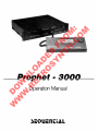
PROPHET
16-BIT
3000
STEREO SAMPLING SYSTEM
OPERATION MANUAL
Stanley
3051 North First Street
San Jose, California 95134-2093
U. S. A.
Jungleib
Phone: (408) 433-5240
Fax: (408) 433-5230
Telex: 4997 150 SEQCIR
PAN: SEQUENTIAL
Radio Frequency Interference (RFD Notice
This equipment generates and can radiate radio frequency
energy and if not installed and used in accordance with
the instruction manual, may cause interference to radio
communications. It has been tested and found to comply
with the limits for a Class A computing device pursuant
to Subpart J of Part 15 of FCC Rules, which are designed
to provide reasonable protection against such interference
when operated in a commercial environment. Operation of
this equipment in a residential area is likely to cause
interference in which case the user at his own expense
will be required to take whatever measures may be
required to correct the interference.
Acknowledgements
San Jose State University Music Department
Stanford Computer Center for Research in Music and
Acoustics (CCRMA)
R. 0. Studios, 3359 Walnut Ave., Concord C A 94519. (415)
676-7237
PowerHouse Studio, 499 Alabama St. #108, San Francisco
CA 94110. (415) 431-0594
Erik Siverson (piano tuning, session performance), 721 2nd
St., Gilroy CA. (408) 847-6789
Studio Technologies (mic pre-eminence), 5520 West Touhy
Ave., Skokie IL 60077.
Orban (Parameteric E Q 622G),
Francisco CA 94107.
645 Bryant St., San
0 1988 by SEQUENTIAL
All rights reserved. Printed in U.S.A.
No part of this publication may be reproduced, stored in a
retrieval system, or transmitted, in any form or by any
means, electronic, mechanical, photocopying, recording,
or otherwise, without the prior written permission of the
publisher.
Every attempt at accuracy has been made. However,
specifications and operations are subject to change
without notice.
CM3000C
ii
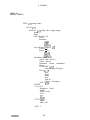
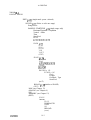
CONTENTS
CONTENTS
CM3000C
title
page
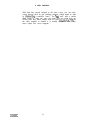
1.
BASIC PLAYING
l-l
2.
BASIC RECORDING
2-l
3.
INSTALLATION
3-l Handling and Transportation
3-2 Audio System
3-3 Other Connections
3-4 Power System
3-l
3-l
3-2
3-5
3-7
4.
USING THE REMOTE CONTROL PANEL
4-l
5.
MIDI CONTROL
5-l Recognized Data
5-2 Master Options
5-3 Enable/Disable Options
5-4 Mode 4
5-l
5-l
5-4
5-5
5-5
6.
PRESETS AND KEYBOARD MODES
6-l Editing Single-Mode Presets
6-2 Creating and Editing Combination Presets
6-3 User-Defined Combinations
6-l
6-3
6-4
6-6
7.
DISK OPERATIONS
7-l Loading the Operting System
7-2 Loading Presets
7-3 Formatting Disks
7-4 Saving the Operating System
7-5 Saving Prests
7-6 Verification
7-7 Naming the Disk
7-l
7-l
7-3
7-4
7-5
7-5
7-6
7-6
8.
DISK CULTURE
8-l
9.
ANALOG PROCESSING
9-l Basic Sound Editing
9-2 Macro-editing
9-3 Analog Parameters
9-l
9-l
9-4
9-5
.. .
111
CONTJZNTS
10.
DIGITAL PROCESSING
10-l Sample Start and End Trimming
1 O-2 Looping
10-3 Digital Signal Processing (DSP)
10-l
10-l
10-4
10-6
11.
RECORDING
11-l
12.
MEMORY MANAGEMENT
12-l
13.
MAPPING
13-l Basic Concepts
13-2 Map Adjustment Methods
13-1
13-1
13-3
14.
OTHER FUNCTIONS
14-1
List of Tables
5-1
5-2
6-l
6-2
7-l
9-l
10-l
11-l
12-1
CM3000C
MIDI MENUS
MIDI IMPLEMENTATION CHART
PRESET AND MODE MENUS
USER-DEFINED COMBINATION MODE
DISK MENUS
ANALOG MENUS
DIGITAL MENUS
RECORDING MENUS
MEMORY MANAGMENT MENUS
iv
5-2
5-7
6-2
6-7
7-2
9-2
10-2
11-2
12-1
1. BASIC PLAYING
CHAPTER 1
BASIC PLAYING
Overview
The Prophet-3000 sampling system embodies some of the finest
thinking that has been done about performance and studio sampling.
It has all the signs of becoming a coveted instrument. But in any
event, it is just plain incredibly fun to use. The smoothness of the
user interface sucks you in. In no time, you are creating your own
sampled presets and customizing their response to your controllers.
No function is ever farther than a few touches away, as the
programmable function switches guide you through an extraordinary
offering of editable parameters and processing functions.
But enough hype. Okay, you bought it. Now what?
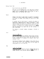
After some words from the legal department, you’ll find the minimum
instructions needed for loading disks and playing factory presets.
These are followed by a more complete discussion of everything you
need to know to basically play the Prophet-3000.
CAUTION! The line voltage of your unit should already be set for
operation from your country’s power source. However, to be sure,
please check the line voltage selector on the back panel.
WARNING! CHANGING THE VOLTAGE SELECTOR MAY
REOUIRE THE USE OF A DIFFERENT LINE CORD OR
ATTACHMENT PLUG, OR BOTH. A DIFFERENT FUSE MUST BE
USED. TO REDUCE THE RISK OF FIRE OR ELECTRIC SHOCK,
REFER SERVICING TO QUALIFIED PERSONNEL.
Instant
Gratification
If you have some experience and just want to know how to get some
sound:
.
CM3000C
Hook everything up and switch power on. (Always a good start.)
l-l
1. BASIC PLAYING
Insert any factory disk marked “1 of 2” and wait a few seconds.
.
When you see “NO PRESETS”, press the second switch (DISK),
then the first switch (LOAD).
?
When prompted, insert the “2 of 2” disk.
.
??
In some cases the system may request that you re-insert the “1 of
2” disk.
.
After the disks load, play your controller.
.
Select presets by turning the dial or sending preset selections
from the controller.
Since “instant gratification” may not do justice to the system, let’s
begin a more methodical account of preset mode.
.
With power off, connect:
the Prophet-3000’s remote control to the chassis front panel,
your performance controller to the Prophet-3000’s MIDI IN,
the Prophet-3000’s audio output(s) to your monitor system,
and power, last.
More information on installation can be found in Chapter 3.
Load the Operating System
Power is on, but before you can do anything else, you must load the
operating system -- which actually creates the Prophet-3000
sampling instrument. The operating system is contained on each “I of
2“ disk in a two-disk set. The reason for this is that it makes it very
tough to find yourself stuck somewhere without a system disk.
.
Switch power on.
The display blinks “Please insert system disk.”
?
Insert any system disk (for example, GRAND PIANO 1 of 2).
The system automatically starts loading, displaying the version
and its creation date.
CM3000C
1-2
1. BASIC PLAYING
If a system disk is in the drive when power is switched on, it
will load automatically. If a non-system disk (2 of 2) is in the
drive, then the display will ask you for a system disk.
After a few seconds the main menu displays “NO
This means that the system is loaded but the sound
still empty. Your options now are to either load
preset(s) from a disk (the DISK switch) or record a
(the RECORD switch, see the next chapter).
PRESETS”.
memory is
all or one
new preset
Load All Presets
To fill the standard RAM requires loading two disks.
?
If the current disk is not desired, remove it and insert the first
disk of the desired set.
From the main menu, press DISK.
.
The disk page appears. ALL PRESETS is initially selected as
the data type.
.
Press LOAD.
This starts loading all presets.
.
Observe the countdown timer.
Each decrement is about i/2 second. The first disk takes about
20 seconds to load its sound data.
??
.
When prompted, remove the “1 of 2” disk and insert the “2 of 2”
disk.
Wait while the second disk loads.
The second disk takes about a minute.
In some cases the system may request that you re-insert the “1 of
’ 2” disk.
?
When the disk page returns, press EXIT.
This returns you to the main menu. At this point the name of
the current preset appears in large letters in the display. The
default preset is the lowest-numbered (1, usually).
.
To load a new disk, just return to the disk page and press LOAD.
You will be warned that memory is occupied. Press
CONTINUE.
CM3000C
l-3
1. BASIC PLAYING
Play and Select Presets
With all presets loaded, you should now be able to play the
Prophet-3000 from your controller, and hear the current preset.
?
The factory disks are in MIDI Mode 1 (receive any channel), so
your controller channel doesn’t matter. If necessary, check
MIDI cabling or routing and system volume adjustments.
Note: If you are having trouble, there is a MIDI Scatus display
which shows what notes are being received in which channels,
and to what voices they are being assigned. To see this display,
press MIDI, then STATUS (and EXIT out).
To select other presets on the Prophet-3000, turn the dial.
.
The number of presets varies with the disk set. For example,
the piano set has just a few presets, but the rock ensemble set
has about 30. These are two good examples of opposite ways in
which the sound memory can be utilized: one set is all multisamples basically supporting one preset -- acoustic piano. The
other set has dozens of different timbres which you can
program as multi-presets in Mode MIDI 4, or later grouped into
multi-timbral combinations and played in Modes 1 or 3.
Display Preset List
To suit either performance or studio settings, the main menu can be
switched to display one large preset number and name, or a list of up
to five consecutive presets -- the current one plus the two above and
two below.
.
To change the display mode so that it lists up to five of the
presets currently in RAM, press LIST.
.
To switch back to the single-preset name display, press LARGE.
In either display mode, you can select presets using the dial.
Adjust Master Tuning
To raise or lower the pitch of the Prophet-3000 against another
instrument (typically, a piano):
.
?
.
From MAIN, press OTHER.
Press TUNE.
Play while turning the dial.
The range is +/-99 cents.
CM3000C
l-4
1. BASIC PLAYING
.
To enable the tuning reference, press the A-440 switch. It toggles
on/off.
.
When done tuning, press EXIT.
Note that this fine-tuning adjustment is temporary, unless you
specifically save all presets to disk (as explained in Chapter 7
Disk Operations).
MIDI Options
All data such as the full MIDI note range, preset selections, and
wheels, are recognized by default of the factory disks. Pressure is
recognized but may or may not be routed through the modulation
matrix, depending on the specific current preset.
If you want to experiment with the MIDI options, for example, Mode
and Channel, you can find them under the MIDI switch on the main
menu. Most of the other options are self-explanatory. To edit, just
cursor to the desired field, and turn the dial. For more information
please see Chapter 5 MIDI Control.
Like master tuning, to permanently retain any MIDI option edits you
must save all presets to disk.
Next Steps
After experimenting with the factory presets supplied, turn to the
next chapter to begin recording your own presets.
Once you learn how to save to disk (Chapter 7), copy the factory
disks for backup purposes.
CM3000C
1-5
2. BASIC RECORDING
CHAPTER 2
BASIC
RECORDING
Overview
Like Chapter 1, this chapter begins with minimum hints for
experienced users. Then it starts over and lays everything out more
thoroughly.
The beauty of the Prophet-3000’s recording system is revealed when
you are multi-sampling a traditional acoustic instrument. The system
includes a pitch detector which automatically locates instrument
samples on the correct keys and adjusts their playback ranges. A
basic release loop and envelope is also set automatically.
When starting out, it is probably best to sample a normal, pitched
instrument -- not drums. Soon you will learn how all defaults can be
disabled or overridden so that any custom arrangement of samples
within presets is possible. There is a user-mapping mode available
which is especially useful for drum work. For more information on
these features see Chapter 13 Mapping.
Instant Gratification
.
?
Clear memory by switching power off, then re-loading the
operating system. (This is not the recommended way to clear
RAM -- but it is quick and easy to explain.)
Press RECORD and set up the mode (stereo/mono) and time
required.
.
Press LEVELS and set the input and threshold levels.
.
Press ARM, then play the note.
.
After processing, audition the note, then press REJECT or NEXT.
.
When finished sampling into this preset, press DONE.
If these instructions didn’t work, read on.
CM3000C
2-1
2. BASIC RECORDING
Deleting All Presets
Let’s assume
that you have been experimenting with the factory
presets and now you want to record your own presets. The first thing
you must do is clear the factory presets out of memory so that there
will be room for your own.
If you switch power off, then you just have to load the operating
system again.
The right way to delete all presets is as follows:
.
From main, press EDIT.
*
With any Single-mode preset selected, press SOUND.
The current preset must display SINGLE in the Mode field.
Most of the factory presets are indeed SINGLE, but if
necessary, select a different preset. If the mode is not
SINGLE, then the SOUND switch does not appear as a choice.
(The explanation for this is in Chapter 6.)
.
Press MEMORY (F5).
.
Press DELETE.
.
Press DELETE ALL.
.
Press YES.
You are returned to the main menu, and the familiar “NO
PRESETS” display.
e
.
Connect your mono or stereo sample input to the MIC or LINE
input(s).
From the main menu, select RECORD.
Entering record mode creates a new preset which will hold all
of the samples that you record, until you exit record mode.
When you exit, the new preset will be numbered and given the
name “UNNAMED”.
On the RECORDING SETUP page, check that the method is
’ AUTOMATIC MAPPING.
.
CM3000C
Set Mode to stereo or monaural, as desired.
2-2
2. BASIC RECORDING
Rate and Time
Check the sampling rate, and dial up the approximate amount of
time you will need.
.
There is a “Time Remaining” field, which always shows the
time remaining for the current mode (mono/stereo> and rate.
Levels
.
Press LEVELS.
.
Play the input and adjust your input levels using the knobs on the
chassis.
“PEAK” indicators are provided. When they light, clipping is
occurring. (There is also a “clipping occured NNN times”
report, after recording.)
.
Use the dial to set the threshold to just above the “noise floor,” so
that the “TRIG” indicator just goes off.
You want the threshold high enough to not trigger falsely, but
low enough to not miss an important attack transient.
Real-Time Monitoring
.
To hear the actual conversion of input through the output, press
MONITOR.
Note: If you are sampling from your system mixer, this
function may create feedback. During recording, the monitor
function is always enabled. It is not possible to see the levels
display and real-time monitor simultaneously.
Trigger Automatic Recording
.
Press ARM.
The recorder is now waiting for input.
.
Play the input. For pitch detection to work correctly, the note
should have correct intonation relative to A-440.
When the input level exceeds the threshold, recording starts
automatically.
When the allocated time has elapsed, recording stops and
processing begins automatically.
When processing is done, observe the clipping report and map
display.
CM3000C
2-3
2. BASIC RECORDING
Audition the Recording
When processing is done, play the sample from the controller or
the PLAY switch.
.
The display reports the root pitch detected and graphically
shows how the sample is assigned to the keyboard. A default
release loop is set automatically.
Note: If you can’t hear anything, check that the controller is
sending notes in the range indicated by the map display. If
desired, use the MIDI STATUS page (mentioned in Chapter I).
PLAY Switch
The PLAY switch is provided for convenience when a keyboard isn’t
handy. The way this switch works is that it imitates a MIDI key hit
with medium velocity (64). Therefore it always requires two presses:
one for the Note On, and one for the Note Off. If you forget to supply
the Note Off, the sound may drone on and on, even if you move to a
different page, where there may be no PLAY switch. If totally lost,
use the KILL switch which is found on the OTHER page (see Chapter
14).
Unpitched and Multi-pitched Samples
If the input is not in tune (relative to A-440), or no pitch was
detected in the sample, you’ll be told this and immediately be shown
the default map and allowed to edit it. The assumption here is that
you have a drum sample and a specific keyboard location in mind for
it. For an unpitched sample, no loop is set,
If the sample input contains multiple fundamentals or significant
inharmonic overtones -- for example, as do bells and bar percussion
instruments -- then the results of pitch detection may be
unpredictable.
Continuing
?
If the sample is not acceptable, press REJECT.
After a protection page, this option deletes the sample and its
range.
Usually the problem will be one of levels, requiring only
another attempt to correct. If the default sample loop is out
of tune, don’t reject the sample becaue of it. You can finetune the loop later (under EDIT-SOUND-MAP-TUNE).
.
If the sample is acceptable, press NEXT.
You are returned to the recording setup to continue sampling.
CM3000C
2-4
2. BASIC RECORDING
.
Record the remaining samples for this preset, similarly.
.
When you have finished recording this preset, press DONE.
You are returned to the main menu, where the preset you just
created is displayed as current.
Adding a Recording
If you leave record mode accidentally, don’t worry, you can still go
back in and add a sample to any ‘preset (assuming there is room in
memory). Use the ADD-REC switch which can be found under the
EDIT page 101.
Naming a Preset
To name a preset:
.
Start from the main menu.
.
Press EDIT.
.
Press NAME (fourth switch).
.
Cursor right to the first character position, and set the character
(using the dial).
The dial always starts from the character already there.
The characters available are O-9, space, and A-Z.
.
Repeat to a total of 16 characters.
The LARGE display can’t fit the last, sixteenth character of a
preset name. The full name will show up on all lists.
.
Press EXIT.
Saving Presets
After recording any preset that you like, save it to disk. At the very
least, you never know when power or the hardware might fail or
someone will kick out a power cable.
Note: New disks must be formatted and the operating system
saved to them, before they can be used for saving. Then, after
saving, you should do a VERIFY operation. For complete disk
instructions, please see Chapter 7.
CM3000C
2-5
3. INSTALLATION
CHAPTER 3
INSTALLATION
Overview
At this point you have probably become familiar with the Prophet3000 through the previous “Basic Playing” and “Basic Recording”
chapters. This chapter discusses handling and location, and the input
and output connections, in more detail.
3-1 HANDLING AND TRANSPORTING
Mounting
As you know, the Prophet-3000 has two basic parts, a chassis and a
remote control panel. The chassis has all of the digital and analog
electronics and the disk drive, but, thanks to VLSI, when rackmounted it occupies only two spaces (3.5 inches). The depth of the
chassis is 14.5 inches.
The chassis contains a highly sophisticated microcomputer system
with state-of-the-art components. As with any other high-tech
instrument, the Prophet-3000 should be treated with as much care as
you would provide an acoustic instrument. Shock or vibration can
damage the disk drive, and loosen internal connectors or socketed
integrated circuits. Avoid temperature and humidity extremes.
For rack mounting, attach the supplied flanges. You do not need to
leave extra rack space above or below the rack chassis.
For non-rack mounting, a set of rubber feet is also included. During
use, the unit should be placed with all feet evenly supported. No
liabilities are assumed for unorthodox mounting or inadequate
support.
If you expect to transport the Prophet-3000 and it is not in a
coverable rack cabinet, then it is imperative to invest in a
professional “road” or “flight” case for it. Cases are made by many
CM3000C
3-1
3. INSTALLATION
manufacturers and should be carried by your music dealer. If you
prefer to build your own, there are firms that sell case hardware.
Drive Head Protector
After removing the head protector from the disk drive, keep it safe
and clean so that it doesn’t contaminate the drive when used again.
To avoid damage to the disk drive, always transport the Prophet-3000
with the head protector inserted. Do not use a disk for head
protection because disks are too thin to properly cushion the head,
therefore they will be damaged. If a damaged disk is then loaded, this
may injure the head.
0
Dust and Cleaning
In general, don’t allow beverages or food around the equipment. For
best floppy disk drive performance, minimize dust exposure, and
vacuum the studio regularly.
To clean the cabinetry, dust or vacuum first and then use mild soap
on a damp, soft cloth. Anything harsher stands a chance of removing
the lettering or dulling the finish.
Disk handling is discussed in Chapter 8.
3-2 AUDIO SYSTEM
Audio Outputs
Here are some details on your output choices:
L/PHONES
This is a two-channel, tip-ring-sleeve (TRS) phone jack. The tip is
always connected to the left channel. If R/MONO is disconnected,
the ring of L/PHONES is the right channel. If R/MONO is connected,
the ring of L/PHONES is disconnected.
R/MONO
This is a one-channel, tip-sleeve (TS) phone jack. If L/PHONES is
disconnected, the R/MONO tip is a monophonic mix of both channels.
If L/PHONES is connected, the tip of R/MONO is the right channel
only.
CM3000C
3-2
3. INSTALLATION
VOICE OUTPUTS 1 - 8
These TS outputs allow each voice to receive independent
equalization or ambience, before going to the external mixer or tape
deck. Presets can play all voices left in the “dynamic allocation”
pool, or be assigned to specific voice outputs. For multi-timbral MIDI
Mode 4 work, you can assign specific MIDI channels, samples, or
presets to specific voices.
Also, you can use both the stereo and individual outputs
simultaneously, because when you insert a plug into one of the
individual output jacks, that voice is removed from the stereo (and
mono) mix. For example, you might use separate voice outputs 1 - 4,
and leave voices 5 - 8 to be taken from the stereo mix.
The L, R and MONO outputs are relay-protected against power on/off
thumps or “pops.” However, the individual voice outputs are not
protected. Also, the individual outputs have a significantly higher
output level than the stereo/mono outputs.
The input impedance of the headphones or preamp/amp being driven
basically doesn’t matter. All of the Prophet-3000 audio output drivers
can handle virtually any load and are fully protected against shorts.
Volume Control
For best signal-to-noise performance, set the VOLUME knob as high
as possible without overloading the inputs of the monitor system, and
use this control only for a temporary volume decrease. The same
applies to MIDI Volume sent from a controller.
VOLUME does not affect the level of the individual voice outputs.
Monitoring
Requirements
As you can see, the Prophet-3000 has a very flexible output system.
For use as a keyboard sampler, using the Prophet-3000 in stereo is
strongly recommended. The analog processing. section includes a
stereo mixer with initial voice positioning, and pan modulation. Only
a stereo configuration will be able to take advantage of the Prophet3000’s true stereo capability and dynamic panning features.
To let you monitor the sample exactly as it is being recorded, the
sample input itself appears at the stereo/mono outputs, and through
the individual outputs for voice 1 and 2 (if stereo). Before recording,
this monitoring is optional. During recording, it is always enabled.
(Due to the sampling and conversion process, there is a very slight
delay on this audio.)
The easiest way to work is to connect input to the Prophet-3000
without going through the board, or, use headphones instead of
routing the Prophet-3000 output to the board. Either of these setups
have the added benefit of discouraging ground loops.
CM3000C
3-3
3. INSTALLATION
Of course, the simple approach may lock you out of using desired
processing gear, and prevents you from doing any quick A/B
comparisons -- encouraging you instead to go through the board. In
this case you must realize that due to the real-time montioring, if
the
board itself.
I len during sampling you will
_._- samole
--...
--source
-....-.is the
~need to mute the Prophet-3000 output so that feedback is not
6%x You can either adjust your mixer manually, or let a
programmable mixer do the work.
External
Processors
Consider the equipment to which you are going to connect the
Prophet-3000. Does it give you adequate tone control? In an ideal
world, all samples would already have all their final equalization -but often the “fit” isn’t known until you assemble the whole puzzle.
This is why pro boards eq each source.
A stereo digital reverb is basically expected and mandatory.
Fortunately, they have also become basically affordable.
Amplifier Power
Think for a moment about your amplifier and speaker system. By
converting the Prophet-3000’s electrical output into the potent
vibrations that you hear, the sound system really does become part of
the instrument. In defining your sound to an audience, as opposed to
merely another piece of gear, the amp/speaker system does
essentially the same work as a piano soundboard or guitar body, and is
just as critical.
Of course you can use anything you like or can afford. But obviously
an instrument of this caliber should not be constrained by a weak
amplifier and muddy speakers. Sixteen-bit sampling calls for a
dynamic range of over 90 dB. Noise and weak amplification can easily
limit your effective range to half of that. What is the point of getting
a super high-fi source like the Prophet-3000 and then swamping it
with noise or clipping it?
For detailed, clear sound (in other words, to prevent clipping)
extraordinary amounts of amplifier headroom are needed. Minimum
requirements seem to be 100 watts per channel for a small studio
system using near-field monitors. Obviously, anything above this is a
question of affordability.
Speakers
Regardless of their size, speakers must be capable of handling the
full amplifier power over the full audio range (20 Hz to 20 kHz)
without distorting. In addition, but no less important, they must be
CM3000C
3-4
3. INSTALLATION
tough enough to withstand the kinds of accidents which typically
come from equipment being disconnected while driving the speakers.
Small speakers have their place, namely, in the studio. For live
performance, three-way systems using 12- or 1%inch woofers are
generally favored.
CAUTION! If it is not practical to use amplifiers and speakers
specifically designed for electronic instruments, or if volume
must be kept low, using your home stereo system will give
reasonable frequency response. But if you go this route, be
careful. Continuous playing of sustained synthesizer sounds can
cause component amplifiers to overheat. Also, the dynamic range
of the sampler places component speakers at risk, because of
powerful bass notes and transients which will damage them if the
volume is set too high.
Sampling Inputs
LEFT/MONO or RIGHT MIC IN
A tip-sleeve phone jack, grounded when not in use. Mic input range is
16 to 180 millivolts rms. Input impedance is 10 kilohms.
LEFT/MONO or RIGHT LINE IN
Also a tip-sleeve phone jack, grounded when not in use. Line input
range is 0.45 to 4.7 volts rms. Input impedance is 240 kilohms.
Inserting a plug into LINE IN disconnects the MIC input. (Therefore
you can leave a mic plugged in without worry that its signal is being
added).
Level knobs are provided on the chassis.
These inputs also function as trigger inputs. For more info, see
Chapter 14.
Please read the paragraph about ground loops, below.
3-3
OTHER CONNECTIONS
CAUTION! Before connecting, be sure that all equipment to be
interconnected is switched off.
Remote Control Panel
The Prophet-3000 remote control panel features a large LCD,
programmable function keys, and a data selector dial. It can be
placed on any convenient work surface.
CM3000C
3-5
3. INSTALLATION
Connect the remote control to the rack chassis, using the included
“telephone-style” cable. The cable runs from the CONTROL PANEL
jack on the front of the chassis, to the left side of the panel.
A few have asked about longer remote cables than the lo-foot one
provided. You can’t use a standard four-wire phone cord. You need a
six-wire version. The remote should work with a 20-ft cable, but we
haven’t tried it, and there are no gaurantees.
And, no, you cannot operate the Prophet-3000 from a distance via the
phone system. If someone plugs a phone into the Prophet-3000 or its
remote, even for a joke, it may damage something (and this is not
covered under warranty).
MIDI
The Prophet-3000 has IN, OUT, and THRU jacks. The THRU jack may
prove handy for extending the bus. The OUT jack has no function
(yet>.
Footswitch
This is a general-purpose tip-sleeve switch controller input. The
footswitch should be normally open, and pressed momentarily to
close.
The footswitch function is programmed from the “OTHER” page, and
may change according to the disk. (See Chapter 14.)
SMPTE/Clock
These are for future use. Both clock jacks are tip-sleeve phone.
IN
Accepts either dc from other equipment, or ac from a tape track.
TAPE OUT
An ac-coupled clock output intended for a tape track.
SCSI
This 25-pin D-connector accepts the Prophet-3002 Small Computer
System Interface (SCSI) hard disk system option.
CM3000C
3-6
3. INSTALLATION
3-4 POWER SYSTEM
Fusing
11ov:
220v:
2A (fast blow)
1A (fast blow)
The fuses are the usual 3AG types. (Check your tool box for spares.)
Power Connection
Power connection is usually left to last in the setup procedure,
because the power switch might accidentally be in the “ON” position.
The POWER ON/OFF switch is on the back panel. Normally, all
equipment in the rack is supplied and controlled from a power strip.
About Grounding and Ground Loops
All Sequential instruments come with a three-prong power plug to
ensure safe grounding with other equipment. The ground prong is
connected directly to the metal chassis. To prevent potentially lethal
shocks, this ground path must not be tampered with.
However, in today’s complex setups, where power lines and several
types of audio and control lines typically run between a dozen pieces
of gear, it is easily possible to create such a large ground system,
that hum and noise are created rather than reduced. The larger the
ground system is, the greater of a tendency it has to develop its own
internal current flows, and these cause hum and noise.
There are several approaches to alleviating this problem. First, the
hum level may depend on exactly how or where the instrument and
amplifier are connected to the ac power line. For minimal hum, use
the same ac outlet for the instrument and its preamp and/or
amplifier, and for all associated equipment, without overloading the
power circuit. This will usually reduce the hum to an acceptable
level.
When using “power strips,” place the heaviest load (usually the
amplifier) closest to the power source, and lightest loads (such as
power adapters) after them. Details like this can sometimes make a
difference.
Regardless of how effective common ac connections are in reducing
general hum, connecting both the input and output of a sampler into
the same system puts it in to the middle of a classic ground loop
situation. This may make it difficult to sample sounds from the
system without accompanying hum. In this case, the easiest way to
defeat this ground loop is to monitor your sampling from headphones
plugged directly into the back panel of the Prophet-3000.
CM3000C
3-7
3.INSTALLATION
But if you don’t want to use headphones, because you must hear the
sample through speakers or processing, for example, then you might
need to cut the shield at one end of one or both of the audio output
cables, or at the input cable(s). As long as at least one end of the
coax cable is connected to either chassis, the signal inside is
protected. Just be sure to mark any cable that you open! Through
careful, “stat-“-grounding techniques such as this--where all grounds
are referenced to only one point--it should be possible to eliminate
all grounding problems.
WARNING! As a last resort, one may be tempted to trade
personal safety for sound quality: it is widely known that you can
quickly defeat some ground loops by using a two-prong adapter to,
in effect, disconnect the ac ground. You must be aware that
tampering with the ac ground in this way can set up a lethal shock
hazard between equipment or between equipment and ground, and
that you do this at your own risk. Sequential is not responsible for
any equipment failure due to incorrect ac power connections, and
is not liable for any personal injury due to electrical shocks as a
result of unsafe grounding practices. It is up to you to check the
power and ground interconnections of all equipment in use. As you
probably know, many older buildings and clubs are notorious for
their poor quality ac wiring. We therefore urge you to verify ac
connections using one of the several “ground-checking” devices
available on the market.
CM3000C
3-8
4. THE REMOTE CONTROL
CHAPTER 4
USING THE REMOTE CONTROL PANEL
Overview
This chapter describes general operation of the remote control panel.
Main Controls
The remote panel contains the following controls and indicators:
LEFT, UP, RIGHT, DOWN cursor switches. (L/R, U/D)
To move between data fields, use the cursor switches. The cursor
acts like a “tab” key between data fields. It does not act as a
“character position” key. When scrolling vertically, it does “wrap
around.” In other words, if you are at the bottom of a column, you
don’t have to press UP five times to get to the top -- instead you
can press DOWN once.
LCD
Eight-line x 40-character, or mixed with 64 x 240 pixel graphic
display of samples, etc.
FUNCTION switches (Fl - F6)
Six, located under the bottom row of the display. Programmable.
DISPLAY ANGLE trimmer.
This adjusts the control panel view to the location. With a
portable display, this turns out to be a necessity, not a luxury.
SELECT dial.
Infinite-turn, velocity-sensing. To change data values or options in
a field, use the dial. The dial causes relative change from the
current setting. It has no absolute position. This way, a value is
not instantly edited to an arbitrary value as soon as you move the
dial. The dial has two speeds: slow turning, increments or
decrements; fast turning, scrolls the data quickly. There is no
direct numeric entry. All numbers start with 1 (not 0). There are
no leading zeroes.
CM3000C
4-l
4. THE REMOTE CONTROL
The central feature of the Prophet 3000 control system is its
interactive display. An LCD of this size allows simultaneous and
versatile display of a variety of control parameters, plus graphic and
oscilloscope functions, without the cumbersome and costly
installation of an external computer or video display. With the
Prophet-3000’s integrated terminal, all operations are much faster
than when you must transfer data back and forth between your
sampler and external computer. And the system is much more
portable, than when you must use an external CRT.
The control/display system has two main applications: preset mode,
and programming mode.
Preset mode -- the main menu -- addresses the needs of the
player/performer on stage. All system and factory disk defaults
assist performing in preset mode (as opposed to programming.)
Editing or Programming mode, for creating new presets. In this
mode, all parameters can be changed.
Pages
We call each control display a “page,” and for reference give each a
unique number in the upper right corner.
IMost page changes are instantaneous. If something takes over two
seconds, the screens displays “PLEASE WAIT” or a similar message. If
the process takes over four seconds, an ABORT function is provided.
In general, line 1 always shows the page title and number. Line 2
almost always shows the current preset and/or line 3, the range.
Prompts and warnings appear on line 7. Line 8 always defines the
function switches.
Function Switches
There are several different control and display methods used in the
Prophet-3000 user interface, and the function switches change their
behavior accordingly.
Binary control (Yes/No)
When the options are simple, YES or CONTINUE is to the left (F2)
and NO or ABORT is to the right (F5).
Programmable Function Keys
This technique is basically menu selection. The function key system
builds a “manual” into the control structure, by suggesting the most
CM3000C
4-2
4. THE REMOTE CONTROL
likely work path and by limiting exit paths to the most useful
functions, depending on the specific context.
The function keys are generally labelled with the most-likely action
placed on the leftmost switch, and lesser priorities to the right. This
is done so that even if you are absolutely stumped, pressing the first
switch will usually continue you along the path of normal operation.
But in other cases, to prevent unnecessary motion, or just to fit all
the available options, some function names may move around,
depending on the specific page. For example, to continue past disk
warnings you generally press the same (physical) switch that got you
there.
In a few cases, where the screen is already filled, you will find some
keys functioning as multiple-choice selectors. For example, this
occurs in looping (AUTO/%/lK/WORD)
and in map adjustment
(FIXED/AUTO). Not that in these cases, the label of the switch
represents the current state, not the choice of “next” state.
Command Buffer
The panel includes a command buffer which stores consecutive
keystrokes made while the system is processing. For example, on
power up, to load all presets you can just press F2 then Fl -- you
don’t have to wait for the disk page to appear before pressing LOAD.
Similarly, when editing samples, if you want to zoom out four times,
you can press the switch four times -- you don’t have to wait for each
zoom to be displayed.
The function switches should be tapped cleanly. If you delay, this may
be read as a second switch press on the next page.
Form-filling
You can think of all the preset data in the Prophet-3000 as an
enormous spread-sheet, with the function switches allowing you to
view different areas of this spreadsheet.
Each function has a display which may contain from one to eight
fields of data. To move between the fields, use the cursor switches.
When you have positioned the cursor at the desired field, to adjust or
set the value of a field, use the dial. Field values can be numbers, but
they are just as often options described by words.
When a function is first selected, the display shows its current value.
If desired, note this value before moving the dial. On the Prophet3000, you never enter data, only change it. Therefore, with no
keypad, no correction is needed for input. Likewise, there is no need
for an ENTER switch.
CM3000C
4-3
4. THE REMOTE CONTROL
Graphic Views
Data graphs are used for waveforms, start/end and loop points, and
envelopes, for displaying and manipulating data in real time. Where
screen size allows, data is displayed numerically as well as
graphically. Cursoring to that value and dialing a new variable
produces a real-time change in operation, and the graphic view is
automatically
updated.
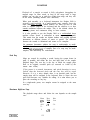
Symbols
This display class includes drawings of keyboard maps, layers, and
splits. Keyboard mapping is usually shown by drawing a horizontal bar
graph above a keyboard image.
Disconnecting the Remote Control Panel
A lot of people like to leave their gear on because it generally
extends component life, and in the case of samplers can save a lot of
time in needless re-loading. This is no problem for the Prophet-3000
chassis. However, it may shorten the life of the backlighting element
for the LCD on the remote panel.
Note: For maximum backlight longevity, if the Prophet-3000 is
going to be on and unused for some time (like, overnight), you
might want to disconnect the control panel (at either end,
whichever is easier). You can do this while power is on.
When you reconnect the control panel, you’ll see the Sequential logo.
To return to normal operation, press a function key (not a cursor>.
You have to press a key that has a function on the current page.
CM3000C
4-4
5. MIDI CONTROL
CHAPTER 5
MIDI
CONTROL
Overview
This chapter looks at the options available for controlling the
Prophet-3000 over MIDI.
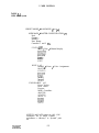
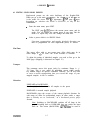
Table 5-l (next page) outlines the MIDI menus, showing how features
are allocated to the various pages.
5-1 R E C O G N I Z E D DATA
MIDI Mode and Channel
All of the included factory disks assume that a standard MIDI
keyboard controller will be connected. All three note messages are
recognized:
Note Off
Note On
Note On=Off
8N kk vv
9N kk vv
9N kk 00
The default MIDI configuration for all three factory disk sets is Mode
1 (receive any channel), with the modulation wheel routed
conservatively, and all receive options enabled. (Disks may come with
their own documentation.)
For your specific setup, you may want to switch the Prophet-3000 to
Mode 3 so that it responds to only one channel. You can do this either
from the Prophet-3000 or from the controller. From the Prophet3000:
CM3000C
.
Press MIDI (or MASTER) to go to ~90.
.
Cursor to the Mode field and set to Mode 3 or 4.
.
If Mode 3, cursor to the Channel field and set as desired.
5-l
5. MIDI CONTROL
TABLE 5-l
MIDI Menu System
PRESET MODE / MAIN MENU p5 or p6
MIDI MAIN / MASTER CONFIGURATION p90
Mode
Channel
Middle C
Note Range
Controller 1 and 2 IDS
STATUS p91
Voice / Note / Channel display
IiKE?
y-v&s
(EDIT)
(EXIT)
MODE 4 p92
Channel / Preset / Voice Assignments
(MASTER)
(STATUS)
y&;s1
EN/DISABLE p93
Preset Select
Pitch Wheel
Pressure
MIDI Controllers
(MASTER)
(STATUS)
(MODE 4)
Ii%:{
(EXIT)
SWITCH and PAGE names are ALL CAP.
Parameters are in Initial Capitals.
(> indicates a “sideways” or “upward” path.
CM3000C
5-2
5. MIDI CONTROL
The Channel field cannot be adjusted unless the Mode is set to
3.
?
If using Mode 4, refer to the end of this chapter for Mode.4 Multi
Routing. There is a separate page for Mode 4 for assigning a
different preset to each channel, and specifying the voices to be
used.
From the controller, send the codes shown:
Mode 1 Omni -- BN 7D 00
Mode 3 Poly -- BN 7F 00
Mode 4 Multi -- BN 7E 00
MIDI Status
When setting up and troubleshooting a system, it is often helpful to
have a way of making sure that MIDI input is actually being received.
To do this, press MIDI, then STATUS. The status page shows what
notes are being received in each channel, and how the notes are being
assigned to the eight voices.
Note: Only if the Mode is 1, does STATUS show notes received
outside of the current channel. If the current Mode is 3, for notes
to appear on the STATUS screen, they must be in the current
channel. If Mode 4, the channels must be “on.”
Saving
MIDI
Parameters
All of the MIDI parameters are loaded from disk. Therefore, to retain
any custom settings such as mode selection and channel numbers, you
must save them to disk. There is no specific disk option for handling
just MIDI parameters. They are saved, verified, and loaded with “ALL
PRESETS”.
Selecting Presets from the Controller
Normally you’ll play the Prophet-3000 from an external controller, so
it will be convenient to select presets from that controller. For all
factory disks, the Prophet-3000 responds to MIDI program selections
(CN pp). If desired, enable these on your controller.
Prophet-3000 presets 1 - 128 correspond to MIDI programs 0 - 127.
If desired, MIDI preset selections can be disabled on the Prophet-3000
(see below).
CM3000C
5-3
5. MIDI CONTROL
Damper/Sustain/Hold Pedal
The Prophet-3000 responds to the pedal code BN 40 vv, by toggling
between envelope rates 4 (pedal up) or 4A (pedal down).
5-2 MASTER OPTIONS
Page 90 also offers the following parameters:
Middle C
The standard MIDI note value for C4 (middle C) is 60. Your controller
may have a different idea. Or, you may want to transpose the entire
instrument into a different key or controller range.
Note Range
The note range defaults to the extremes of 0 and 127. There is no
wraparound for keys. The Prophet-3000 plays all keys at their true
pitch, presuming of course that the extreme ranges have been
mapped. You can decrease the range to make the Prophet-3000
respond over a specific key range.
Control IDS
Two MIDI controllers (status BN) can be routed to any of the
destinations available in the analog modulation matrix. This page
defines which MIDI controllers become “Controller 1” and “Controller
2” inside the modulation matrix. For example, on the factory disks,
Controller 1 is set to 1, which is the modulation wheel ID number.
Controller 2 is generally left undefined. These settings hold for all
presets on the disk. However, using the modulation matrix each
preset can route Controller 1 or 2 quite differently.
Here is a list of ID numbers for some popular controllers:
ID
I-2
:
7
8
10
11
16-19
Controller
Modulation wheel or lever
Breath controller
Foot controller
Portamento
Main volume (in addition to normal effect)
Balance
Pan
Expression controller
General purpose 1 - 4
...
CM3000C
5-4
5. MIDI CONTROL
While intended for use with continuous controllers (numbered through
63), switch controllers (64-121) can also be used. In this case, off
equals value 0 and on equals value 127.
Recognition of all controllers can be disabled under EN/DIS (see
next).
5-3 ENABLE / DISABLE OPTIONS
Page 93 allows you to enable or disable the Prophet-3000s response
to:
Preset
Selections
CN PP
Pitch Wheel
EN 1s ms
Pressure
Channel
Poly
DN vv
AN kk pp (interpreted as Channel pressure)
Controllers
BN cc vv
On the factory disks, all of these options are enabled. If you are not
using these functions, disable them to obtain a slight increase in the
Prophet-3000’s MIDI response time.
5-4 MODE 4 p92
This page provides a table which allows you to assign any preset to
any MIDI channel (or ignore any channel), and allocate a number of
voices for each. This allows complete flexibility for multi-timbral
sequencing or special controllers.
Here is an example of what Mode 4/Multi mode can do. For clarity,
the example shows preset names, although these don’t appear on the
display:
Channel
1
2
3
4
5
6
7
...
16
CM3000C
On/Off
On
Preset
1 Bass
2 Slap
4 2 ClosedHat
4 3 OpenHat
5 0 Snare
1 8 Ster FX
on
On
On
On
On
Off
Off
5-5
Voices
l-2
l-2
3
3
4
5-8
5. MIDI CONTROL
With both bass sounds assigned to the same voices, you can easily
switch between them by just switching channels (which might be done
by channelling a controller “zone”). The “hat trick” does a similar
thing, except by using one voice you ensure that one sound does cut
off the other. Any stereo samples must use pairs l/2, 3/4, 5/6m. So
the effect assigned to channel 6 is actually duophonic (two voices
stereo equals four voices assigned).
CM3000C
5-6
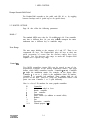
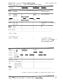
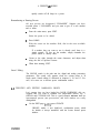
SEQUENTIAL Prophet-3000 Stereo Sampling System
DATE: MARCH, 1988
MODEL 3000, Level 2.0
MIDI IMPLEMENTATION CHART
-__-------------------------------------------------------------------------------------------Transmitted
Recognized
Remarks
Function
___-------------------------------------------------------------------------------------------Basic
Default
1
1
Channel Changed
Disk-programmed.
l - 1 6
1-16
__-_-------_--------_________^__________------------------------------------------------------Default
X
Mode 1
Disk-programmed.
Mode
Messages
X
Mode 1, 3, 4
**********
Altered
X
O-127
Note
X
**********
O-127
Number True voice
-__--____-_____-________________________------------------------------------------------------Programmed via modulation
Velocity Note On
X
0
Note Off
X
0
matrix.
---------------^-__---------------------------------------------------------------------------9,
PresKey’s
X
0
Ch’s
X
0
sure
----------------------------------------------------------------------------------------------Pitch Bender
X
0
----------------------------------------------------------------------------------------------Control
Change
All continuous and
switch controllers.
X
0
Two MIDI controllers
definable as Controller 1 or 2.
These are routed via
the modulation matrix.
-----------------------------------------------------------------------------------------------
Prog
Change True #
o O-127
******ey+
o O-127
l-128
System
X
X
Exclusive
System
: Song Pos
x
X
: Song Se1
X
X
X
Common : Tune
X
_---------------------------------------------------------------------------------------------X
System : Clock
X
Real Time: Commands x
X
----------------------------------------------------------------------------------------------Aux
: Local On/Off x
X
: All Notes Off x
0
Mes: Active Sense x
X
X
sages
: Reset
X
----------------------------------------------------------------------------------------------Notes
In Mode 4, presets are assignable to channels and specific voices.
-----------------------------------------------------------------------------------------------
Mode 1 : Omni On, Poly Mode 2 : Omni On, Mono ********=
Mode 3 : Omni Off, Poly Mode 4 : Omni Off, Mono ********=
0 : Yes
x : No
6. PRESETS & MODES
CHAPTER 6
PRESETS AND KEYBOARD MODES
Overview
This chapter discusses the two types of presets which are available on
the Prophet-3000, and the first level of editing: arranging, layering,
and crossfading presets.
Table 6-1 (next page) outlines the editing functions discussed in this
chapter. Table 6-2 focuses on the options available under userdefined preset combination.
Two Types of Presets
To program the Prophet-3000 you have to know only one nuance: the
Prophet-3000 has two kinds of presets: low-level single-mode prese=
and high-level combination presets.
A single-mode preset is what you get after recording samples. Singlemode presets can contain as few as one sample, or an entire keyboard
full of multi-sampled or multi-timbral recordings. You can edit the
analog parameters of single-mode presets either as a whole, or by
individual sample ranges. The individual ranges can also be processed
digitally (trimming, looping, scaling, etc.), Loading or recording
single-mode presets generally uses a significant amount of sound
RAM (unless the samples are already in memory).
In contrast, combination presets have no sound of their own. Instead,
combination presets “point to” single-mode presets which do have
sounds, and organize them in various ways. Because com?%ation
presets don’t have their own sounds, you can’t edit the sound of any of
them -- and the control system prevents you from trying. To edit the
sound of a combination preset, you would edit the individual singlemode presets comprising the combination. Because only a few
parameters change, creating new combination presets doesn’t use
very much memory.
Since the two types of presets have completely different makeups, it
stands to reason that editing them involves two completely different
techniques. First we’ll discuss what you can do to a single preset,
then discuss combinations.
C M3000C
6-I
6. PRESETS 6: MODES
TABLE 6-l
PRESET AND MODE MENUS
EDIT ~101 (if single-mode)
Preset/Mode
Fine Tune
Transpose
Direction
CREATE p 102
Split LMode
Split At
Left/Right presets
Left/Right
Transpose
CREATE ~103
Velocity Switch
Threshold
Low/High presets
CREATE p 104
Layer
A/B presets
A/B Levels
Detune B
CREATE ~105
Crossf ade
Controller name
Low/High presets
CREATE p 106
User-Defined (see Table 6-2)
DEL (if not single mode)
SOUND (see Chapter 9)
ADD-REC (see Chapter 11)
NAME
A-440
(EXIT)
The CREATE page changes with the user’s choice of mode.
CM3000C
6-2
6. PRESETS & MODES
6-1 EDITING SINGLE-MODE PRESETS
Single-mode presets are
When you go to the main
is the mode. Be aware
depending on whether
combinations.
.
the sonic backbone of the Prophet-3000.
editin page, the first iece of info ou see
that tR e appearance o !i this page cx anges,
the mode is SINGLE, or any of the
From the main menu, press EDIT.
The EDIT page (~101) shows the current preset name, and its
mode. You can change the current preset at any time. But the
mode is a report only. You can’t change the mode here.
.
Select a preset which is in SINGLE Mode.
Fine-tune, transposition, and sample playback direction can
then be programmed for each single-mode preset, as follows.
Fine-Tune
This preset offset adds to any master tune offset which may be in
effect. Range is +/- 49 cents. The A-440 reference is available.
To adjust the tuning of individual samples, you need to first go to the
MAP page. (Mapping is discussed in Chapter 13.)
Transpose
This parameter moves this preset (only) by semitones. Range is +/127 steps. This is very useful for positioning presets within specific
key number ranges for specific controllers. However, you do not want
to exert so much transposition that you exceed the range of your
mapped samples. A-440 is available.
Direction
FORWARD or BACKWARD
Switches playback direction for all samples in the preset.
FORWARD is normal sample playback.
BACKWARD plays the reverse of the current playback direction for
each range (to allow for multi-timbral maps). In other words, a range
that is already set to “backward,” in a backward preset, plays
forward.
Note: Switching to BACKWARD switches off all loops in the
preset. Switching back to FORWARD does not switch the loops
back on. This action (BACK-FOR) cah=fore be used to
CM3000C
6-3
6. PRESETS & MODES
quickly switch off all loops in a preset.
Renumbering or Naming Presets
All new presets are designated “UNNAMED”. Suppose you have
recorded preset 1 UNNAMED, and you want to give it a new number
and or name:
From the main menu, press EDIT.
.
?
.
?
Select the preset to be edited.
Press NAME.
With the cursor on the number field, dial in the next available
numbers.
If a number that you want to use is already used, there is a
simple remedy. To free up the number, simply renumber the
preset which is already there.
.
Cursor to the right, through the name characters, and adjust them
using the dial or up/down cursors.
.
When done naming, EXIT.
Sound Editing
The SOUND switch is the path into the digital and analog processing
parameters. This switch only appears when the current preset is in
single mode. Sound editing is discussed in chapters 9, 10, and 13. For
now, let’s move on to discuss preset combination modes.
6-2 CREATING AND EDITING COMBINATION PRESETS
Let’s assume that you have loaded the ROCK ENSEMBLE disk set.
Suppose that you want to combine two single-mode presets, say, 1
ORGAN and 6 TENOR SAX. This is a good example because both are
instrumental presets (not percussion), and their timbres are easily
distinguished.
.
On the EDIT page (plol), press CREATE.
CREATE makes a new high-level, combination preset, which
by default is always numbered with the lowest unused preset
number.
CM3000C
6-4
6. PRESETS & MODES
.
The cursor defaults to the Mode field, which is SPLIT. Dial
“LAYER”.
.
Cursor to the preset A line and dial in one of the presets, such as
1 ORGAN.
??
.
Cursor to the preset B line and dial in the other preset, 6 TENOR
SAX.
Play the preset from the keyboard, and adjust the preset levels
and detuning of the B preset (sax) as desired.
These adjustments are part of the current combination preset.
They do not affect the original single-mode presets.
.
To try one of the other combinations, just change the mode. I
ORGAN and 6 TENOR SAX will be split or cross-faded, as you
please.
.
When done, exit.
This is the basic procedure for creating any combination
preset.
Modes
Here are some details on each of the combination modes:
SPLIT
One preset calls up presets designated Left and Right, and can
transpose them. Transposing is very handy for centering the most
played ranges in the available keyboard octaves. Up to eight keys can
be played. If the voice allocation mode is dynamic (as set on the
analog output page), then you can play up to eight keys per side,
instead of four. This mode only controls which side of the keyboard
plays which preset. It is a separate, analog operation to pan all the
voices of a preset to the left or right so that they only come out of
one side of the stereo mix.
VELOCITY SWITCH
One preset calls presets designated Low and High, which respond
below and above the velocity set by the Threshold field. Up to eight
keys are playable.
LAYER
One preset layers two presets designated A and B. Their Levels
default to 50 but are adjustable from 1 - 99. The B preset can be
detuned -49 - +49 cents. This is a “four-key” mode.
CROSSFADE
This is a layer mode, except that the continuous mixture between the
Low and High presets is controlled by modulators such as the
CM3000C
6-5
6. PRESETS & MODES
keyboard, velocity, pressure, and MIDI controllers 1 and 2 (as defined
on the MIDI MASTER page). With no controller depth, the Low preset
plays full. With medium depth there is an equal balance. And with full
Depth, the High preset plays full. This also, is a “four-key” mode.
6-3 USER-DEFINED COMBINATIONS
The modes just mentioned are good for basic keyboard performance
applications. But we couldn’t have slept at night without providing
the Prophet-3000 with a wide open, general purpose way of mapping
presets across several performance dimensions. USER-DEFINED
combination mode allows you to layer up to eight presets (the voice
limit) and define the range of each, so that any combination of
doubling and splitting is possible, with the exact layering dependent
on the note number.
But USER-DEFINED mode also allows you to set velocity ranges for
each preset, so that discrete or overlapping velocity layers can be
controlled by touch.
Finally, within USER mode, each preset can receive its own level
adjustment, transposition, and detuning.
Table 6-2 (next page) shows the menu system for user-defined
combination mode.
Adding and Removing Presets
USER mode is initialized with the two presets set for the other
combinations. They become the first two presets in the USER preset
list. The low and high keys of their ranges default to the extremes CO
and G9.
.
To add more presets, first press VIEW.
VIEW shows the keyboard model with two horizontal bars over it.
These bars indicate that the two presets range across the entire
keyboard. The first bar corresponds to the lowest preset number,
on down.
CM3000C
.
To add a preset to the USER list, press ADD. After selecting the
desired addition, press GO.
.
REMOVE operates similarly.
6-6
6. PRESETS & MODES
TABLE 6-2
USER-DEFINED COMBINATION MODE
CREATE ~106
User-Defined
Preset list
Low/High Key
VIEW ~107
(LIST)
EDIT-MAP p 108
Low/High Key
Low/High Velocity
Level/Transpose/Detune
(VIEW)
(LIST)
(ADD)
(R EMOV E)
(EXIT)
ADD ~109
(VIEW)
(LIST)
(EDIT-MAP)
GO
;f;$W
REMOVE p 110
[ET?
[yDITTMAP)
(GEOXIT)
(EXIT)
(EXIT)
CM3000C
6-7
6. PRESETS & MODES
?
When you have assembled all of the presets that you want in this
combination, select EDIT-MAP and set the following fields for
each preset:
Low/High Key
Low/High Velocity
Level
Transpose
Detune
As a simple exercise, use this mode to create eight layers of one
preset, with each at a differen-t level, transpose, and detune. Then
adjust key ranges and velocities, to begin mixing up the layering with
different notes and attacks. While the voice limit of eight is the
vertical maximum, you can combine up to 64 presets horizontally.
CM3000C
6-8
7. DISK OPERATIONS
CHAPTER7
DISK OPERATIONS
Overview
This chapter contains instructions for operating the disk system. The
next chapter summarizes our best recommendations for day-to-day
living with floppy disks.
Note: The Prophet-3000 contains a quad-density drive which
requires type 2HD disks. These can be easily identified by the
“HD” logo, andadditional square hole opposite of the writeprotect hole. Type 2DD will not work.
Table 7-1 (next page) outlines the organization of the disk system.
7-1 LOADING THE OPERATING SYSTEM
The Prophet 3000 is a general-purpose system. So, unlike its
predecessors, it contains very little ROM -- only enough to load its
large RAM.
The system software is automatically loaded from disk the first time
power is switched on. The version number is displayed momentarily.
To save time, after the operating system has loaded once, it doesn’t
load again (unless power has been switched off).
In a multi-disk set, only the first disk has the operating system.
Disks in multi-disk sets must be loaded in specified order.
If there is any disk error while loading the operating system, loading
aborts. Try a different disk.
If you load a disk which contains a different operating system than
the one currently in the Prophet-3000, it tells you and lets you choose
the desired system.
CM3000C
7-1
7. DISK OPERATIONS
TABLE 7-1
DISK MENUS
DISK pl0
All Presets
Preset List
One Preset
Operating System
LOAD pi5
ABORT
SAVE p63
ANALOG
CONTINUE
ABORT
VERIFY p45
ABORT
NAME ~52
YES
NO
FORMAT ~54
CONTINUE
ABORT
(EXIT)
CM3000C
7-2
7. DISK OPERATIONS
7-2 LOADING PRESETS
From PRESET/MAIN p5 or p6, press DISK. The disk menu can also be
reached from several other strategic points. The disk menu is a
matrixed arrangement which allows you to use the dial to select the
type of data to be transferred, and then select the actual operation
with a function switch. The various combinations are explained
below.
The disk drive sub-system is rather smart. It corrects some types of
floppy disk media errors. It always knows when you insert or remove
a disk, and what the disk name is. If you are loading a multi-disk set,
it provides the necessary prompts to ensure correct loading.
Load All Presets
If you have loaded any of the factory disks, then you are familiar
with this option by now.
The first disk in a set contains in addition to the operating system,
preset data and analog parameters, and about 20% of all the sample
data. The second disk is all sound data -- the remaining 80% of full
memory.
Loading
Analog
Parameters
The LOAD confirmation screen provides a LOAD ANALOG choice for
this first disk. This is handy because it saves time when you want to
restore edited parameters from the first disk and don’t need to reload the sample data (because you haven’t edited it).
Disk Errors
Disks being what they are (fallible material), it is always possible
(and basically inevitable) that loading errors will occur.
If a disk error occurs, you are notified of this by the fact that loading
stops, and the display prompts you to press a function switch to
continue loading data. Press this switch as often as required to
complete the loading. If you have to intervene often, this means that
the disk has been magnetically or physically damaged. Some of the
sounds may now play with pops, clicks, or scratches. But the
important ones could be fine.
If the disk is really bad, it may just abort and refuse to continue.
CM3000C
7-3
7. DISK OPERATIONS
Load Preset List
Selecting this function and pressing LOAD gets the directory of the
current disk. This directory is held in its own buffer and does not
affect the list of internal presets.
Scroll through the displayed directory using the dial. For
convenience, a LOAD ONE option is provided here. When done, press
EXIT, which returns you to the disk menu.
Load One Preset
Load One Preset is an extremely useful function
build up entirely new disks by taking individual
disks. Also of prime importance, when editing,
you to quickly restore the original version of a
accidentally
mangled.
as it allows you to
presets from separate
this function allows
preset that you have
All presets load into the same preset number which they already are
on disk. For example, preset 12 loads into preset 12. This means that
if there is already an existing preset 12, for example, you may want
to renumber it before attempting the load.
When attempting to load one preset, the Prophet-3000 checks the
source’s size to be sure that it will fit, before allowing you to erase
an existing preset in the “target” location. Error messages will appear
if there is not enough memory available for the complete source
preset to fit. (If necessary, go to the MEMORY area and make room .
- - see Chapter 12.)
7-3 FORMATTING DISKS
The first step after obtaining disks is to format them. All new disks
must be formatted by the Prophet-3000 before they can be used for
saving. Formatting erases all previous contents.
Note: Use only quality 2HD disks.
To format a disk:
.
?
?
Check that the disk to be formatted is not write-protected. That
is, the protection window should be closed.
Insert the disk to be formatted into the drive.
Press FORMAT.
As a precaution, the system will tell you if the disk has
anything on it at all -- even unrecognized data.
.
CM3000C
Press CONTINUE.
7-4
7. DISK OPERATIONS
A formatted disk is totally blank and is given the label “0 of 0”. When
you use a blank disk to save all presets, the current operating system
will first be saved and verified automatically.
7-4 SAVING THE OPERATING SYSTEM
Since the current operating system is automatically saved whenever
it is needed, you don’t need to worry about it. This option will prove
most handy for updating older system disks.
Don’t bother to save the operating system to any disk which you
intend to use as a “2 of 2”, since it will just get recorded over,
anyway.
7-5 SAVING PRESETS
Disks must be formatted before they can be used for saving presets.
When memory is over 20% full, two disks are needed.
Saving All Presets
?
?
.
?
Check that the disk is not write-protected (window closed).
Select ALL PRESETS, and press SAVE.
If the current disk is not blank, you will be asked to confirm the
operation.
If a second disk is required, you’ll be prompted.
Note that, for convenience, you can use any formatted disk for
saving as a “2 of 2”. If the disk is unexpected, the system tells
you, but allows you to continue anyway. If the disk contains
the operating system, this will simply be written over with
sound data.
.
When saving is done, the disk page reappears.
Saving System Options
Saving all presets also saves all of the current “system-level” options,
such as Master Tune, and the MIDI configuration. Specifically, the
system parameters saved to disk with all presets are:
Master Tuning
Complete MIDI configuration (MASTER, ENJDIS,
Recording Setup
Footswitch
Trigger
CM3000C
7-s
MODE 4)
7. DISK OPERATIONS
Saving Analog Parameters
To save time when digital data has not been edited, it is possible to
save analog parameters alone. Start to save all presets. When you
attempt to save over a disk, you are warned. On this warning page
there is an ANALOG option. Press it!
7-6 VERIFICATION
VERIFY is left as an option, to allow you to judge for yourself when
must realize
that
n e e d t o use it. However,
YOU
YOU
after saving, the only way to be sure that- the data has been saved to
disk correctly is to verify it by reading the disk and comparing it to
RAM. This is what VERIFY does.
Verify All Presets
If the disk verifies, normal operation is resumed. Otherwise an error
message will appear. If a disk fails to verify, try saving to a different
disk and verifying that disk. If a disk fails to verify repeatedly, it is
probably defective. (As these floppies are not cheap, it pays to buy
100% certified, guaranteed disks, and keep your receipts. The
author’s experience with 2HDs is that a box of ten usually contains
one bad disk, and often two.)
Verification can also be used to prove that memory is identical to any
disk, for example, to see if RAM and a disk have the same operating
system.
7-7 NAMING THE DISK
After formatting a disk, take the opportunity to name it (up to 20
characters), and perhaps in so doing keep yourself from accidentally
erasing it. To select the character position, use L/R. To change the
character, use the dial or U/D.
CM3000C
7-6
8. DISK CULTURE
CHAPTER 8
DISK CULTURE
Overview
Having covered disk operations, we review the basic guidelines for
living with disks.
The Reason for Disks
The Prophet-3000 has two kinds of internal semiconductor memory.
First, permanent read-only memory (ROM) contains the “boot”
program which loads the operating system into RAM. (For the record,
this name comes from the model of the system “picking itself up by
its own bootstraps.“)
The second type, random access memory (RAM), is used for the
system and preset memory. Unlike the boot program, RAIM is
volatile. This means that the contents of the memory are lost when
power is switched off. The reason for disks, then, is permanent and
convenient storage of RAM. Of course because RAM is so easily
reprogrammed, disks also give you the ability to easily update the
system and to build up vast libraries of sounds.
When you consider the power and flexibility they give you, disks are a
great bargain--at any price being charged today. Ultimately, the disk
system really makes possible whatever you will achieve with the
Prophet-3000. Be sure to keep plenty of disks on hand, so you can
quickly record inspirations as they occur, as well as record versions
of your ongoing work which might serve you in the future. Take the
time to back-up, protect, and keep track of your disks according to
whatever system works for you.
Precautions
Besides the large capacity, obvious compactness, and mechanical
write protection, this disk system has the significant advantage of
housing the disks in protective cartridges. This is an immense
improvement on the open, St-inch format, providing much greater
portability and reliability.
CM3000C
8-1
8. DISK CULTURE
This technical advance does not relieve you of responsibility for
protecting your investment of time through correct handling and
storage practices, thoughtful labelling and write protection, and
systematic backup procedures.
Until you get very familiar with the Prophet-3000, you should act as
if a disaster can always occur. At the very least, it & always possible
for there to be a power dropout, and any such occurence will most
likely erase the sound memory. You will lose any work which you did
not specifically save to disk before the failure. Taking the time for
proper backup is an essential part of operating all computer-based
systems. Especially at first, you will rarely be sorry. After you have
gained more understanding of the instrument and confidence in your
operations and the power source, you will have a better idea of how
much saving (and verification) is prudent.
Disk Drive Maintenance
Almost unbelievably, the best maintenance is no maintenance. Leave
the drive alone. Instead of cleaning the drive or head regularly, use
good practices to avoid getting it dirty in the first place. Dust is very
bad for disk drive heads. Vacuum the studio periodicaily to minimize
dust. The drive has its own door, but it doesn’t hurt to cover the
instrument when it it is not in use (as long as power is not on!). You
can vacuum the drive itself, but only bring the hose head just up to
the drive slot. Never put anything in the drive besides a properlyoriented head protector or disk.
Head cleaners should be used sparingly, and only after receiving some
evidence that you need them (such as erratic disk operation, or lots
of loading errors). Otherwise, they will reduce head life due to their
abrasive action.
Disk Selection and Quality
The expected lifetime of these disks far exceeds the age of the
marketplace, so virtually no, solid evidence of performance is
available. This makes it very difficult to recommend disk brands.
Comparative reviews of disk physical qualities appear from time to
time in computer magazines. The most important qualities are
perhaps flux density and retentivity, but uniformity, and evenness of
coating are important for minimizing head wear. However, overall
longevity and durability depends as much on material and
workmanship as it does on magnetic properties. You may want this
data ten years from now.
In other words, disks are precision devices where every part and
aspect is critical. The question basically comes down to this: Is it
worth a dollar or two (per box) to risk damaging your drive and losing
your sounds or sequences by using low-grade, “no-name” disks? It is
true that often the differences between disks are only in the
packaging, as there are many more labels than true manufacturers.
CM3000C
8-2
8. DISK CULTURE
But the problem is that there is at least an equal chance that “noname” disks will be quality rejects from a name manufacturer, as
there is that they will be a genuine bargain.
What is often for otten is that reliable suppliers and dealers are at
least as importan f as the manufacturer or the label. There is nothing
on a package to tell you a box hasn’t sat baking in a warehouse or
store room for a month. This suggests buying at higher-volume
retailers.
Handling
The disk is protected by the cartridge, but it is not invulnerable.
Treat it like an audio master.
If you want to keep your disk drive and record/play head clean (and of
course you do), you have to keep the disk cartridges and disks you put
in it clean. This means keeping your hands clean, and being careful
where you set disks. You may be performing thousands of disk
operations, so for best performance strictly minimize contact with
dirt, dust, smoke, ash, liquids, foods, magnetic fields, temperature
extremes, and direct sunlight. When disks are not in immediate use,
box and cover them. They should be stored vertically.
Note: It is not a good idea to leave disks in the drive overnight,
for example. This is because doing so leaves the shutter open,
allowing dust to enter. Eject the disk so that the built-in door can
cover the drive.
The recommended operation and long-term storage temperature
range for these disks is a rated 50 - 140 F (10 - 60 C). For temporary
storage for transportation, do not expose below -40 F (8 C).
Do not routinely slide open the protective shutter to play with the
disk inside nor try to clean the disk itself. If the shutter has been
damaged or is missing, or if there is any blemish on the disk surface,
discard the disk, as any contamination of the disk surface may
damage the recording head.
There are correct ways to label, too. Always put the correct-size or
smaller label within the location outlined on both sides of the disk.
Don’t layer labels: use only one thickness on a disk or you may cause
misalignment of the cartridge in the drive, or cause the cartridge to
stick in the drive. Write on labels with soft felt pen. Don’t use pencil,
and don’t use erasers (because they leave particles).
Stray Magnetism
There is a lot of unnecessary panic about stray magnetism. The flux
density at the disk recording head is very powerful and very localized. It does not even penetrate half the thickness of the disk
material itself--which is why you can have double-sided disks. It is
CM3000C
8-3
8, DISK CULTURE
highly unlikely that your disks will ever see this amount of
concentrated magnetic power outside of the drive.
On the other hand, anything can happen, and it on1 takes one altered
bit in just the right place to throw everything off. rhe following have
been mentioned as possible sources of significant magnetic disruptions:
Power transformers (basically, all electronic equipment)
Loudspeakers (magnets)
Tape decks (the erase head)
Telephones (the earpiece and bell)
Power cables
Tape demagnetizers
Televisions and CRTs
Airline X-ray equipment
You will have to decide to what extent these items can or need to be
avoided. It basically depends on your level of paranoia. For example,
if you are really that concerned about your speaker cabinet, or the
transformer in your power amp, try passing an extra copy of a disk
directly over it and see what happens when you load it. Try leaving a
spare next to your CRT for a week. Odds are there will be no change
or additional degradation. (Knowing this may serve as a stress relief.)
Write
Protection
Looking at the top of the disk, the square hole at the lower left is the
write protection window. Turning the disk over, you find a sliding tab
which is used to close and open the window. This slider makes it easy
to protect and unprotect disks. No more stickers to bother with.
To enable recording on the disk, close the protection window by
push-the slider up.
To protect the disk from recording, open the protection window
by pushing the slider down.
It may help to remember that this system works exactly like audio
cassettes: opening the window rotects the recording. (You may need
to use a pen-point to move the 5
slider.
Backup
and
Verification
If you are going to be able to go back to any stage of work, you must
save data along the way. You don’t have to have final sounds before
saving. Save anything you have done which might not be easy to
replace.
CM3000C
8-4
8. DISK CULTURE
It is good practice to use at least two backups, alternately saving to
one then to the other. This protects you from failure of a backup (or
loss of attention to what your are saving over).
Note: The importance of following a Save with a Verify operation
cannot be overemphasized. It is the only way to ensure that what
you have saved to floppy will load without error. Previous
successful saves to a disk do not guarantee that future saves will
be error-free. A single bad bit caused by a dust speck or spot
defect on the disk surface can render a stored sound unusable.
There is no way to detect such errors during the save process. To
be sure they did not occur, you must verify.
In the excitement of creation it is often difficult to take the time to
properly identify, document, and back-up your disks, but this type of
organization will save you much more time overall and is very
important if you are going to make full use of the Prophet-3000.
Constantly trying to think of names and descriptions is often
distracting, so you might just note the date and possibly the
approximate time, before getting on with what you were doing.
Instead of writing on the disks all the time and constantly replacing
labels, it is usually more practical to give each disk a code number,
and update the disk descriptions on a separate card or definition form
of your own design. This will really help keep things straight, and
enable you to keep track of more sounds without accidentally erasing
ones you had wanted to keep.
Maintain a set of your most important disks in a safe place, away
from your studio, possibly even in a different county. If something
happens to your Prophet-3000, you can at least in principle replace it.
But if your custom disk collection is stolen or burns up in a fire--now
that really hurts.
On at least a yearly basis, it is a good idea to check that your
important backups load with minimal errors.
Loading
Errors
In a complete disk loading, several million bits are transferred. With
the number of disk operations that you will be performing, it is
statistically inevitable that an occasional bit will be lost. When data
has actually been lost, loading is stopped and the error message
appears. Since one or even a few word errors on a disk may be
inaudible, or may not affect all samples, you are allowed to continue
loading. Loading will proceed, until another “data lost” error is
encountered or the load is completed. Even if there are a lot of
errors (indicating that the disk was damaged), you can complete the
load. This makes it possible to at least load whatever data remains on
a problem disk. Some samples may have “clicks” in them, which are
caused by the missing sample data. But, sometimes this is better than
nothing.
CM3000C
8-5
8. DISK CULTURE
It is normal for error-detection to occur periodically. But if the
error-detection pattern of a disk suddenly becomes erratic, this
indicates that the disk has degraded. If you have reason to think the
degradation may have been caused only from magnetic interference,
after copying the disk (for safety), reformat it and see if it then
saves, verifies, and reloads. Otherwise, the disk may be suffering
from a physical defect and should not be used more than necessary to
determine that it is bad.
CM3000C
8-6
9. ANALOG
CHAPTER 9
ANALOG PROCESSING
Overview
This chapter discusses the analog “macro” processing functions and
supporting parameters. The macros can be thought of as presets
whose scope are limited to each of the three main modules: filter,
amplifier and modulation. Individual macros can be edited at either
the preset or sample level. So, we must begin by discussing how to
choose between editing complete presets or individual sample ranges.
Table 9-l (next page) outlines the analog system.
9-l BASIC SOUND EDITING
Entering Sound Edit Mode
Recall from the previous chapter that only single-mode presets
contain sounds which can be edited. Therefore, to do any analog
editing:
.
?
.
From the main menu, press EDIT.
Select any preset which is in SINGLE mode, as shown on EDIT
p101.
Press SOUND.
SOUND only appears as an option when you have selected a
single-level preset.
You are now at EDIT SOUND ~112. Notice that at this point
you are only allowed to select presets which are in SINGLE
mode. In this mode all combination presets are ignored,
because it only makes sense to edit the sound of single-mode
presets. To edit preset combinations, you must EXIT out to the
sound edit page, and use CREATE.
CM3000C
9-l
9. ANALOG
TABLE 9-1
ANALOG MENUS
EDIT ~101 (single mode)
S O U N D ~112
ANALOG ~113 (either all or single ranges)
Preset
Range
Filter (detail) p 114
Cutoff
Resonance
(AMP)
(MOD)
(ENV-1)
Amp Envelope (detail) p 115
Levels 0 - 3
Rates 1 - 4A
(FILT)
(MOD)
(ENV-1)
Modulation (detail) p 116
Source (nine sources)
Source Amount
Destination (sixteen destinations)
Route
ENVELOPE 1~117
(same as Amp Envelope)
LFO-1 ~119
Rate
Shape
Delay
Sync
Fade-In
Fade-In destination
LFO-2 ~120
DETAIL
COPY p122
Destination Preset
Module
Source preset
PLAY
(GEOXIT)
OUTPUT ~12 1
Level
Initial Pan
(EXIT) **
??
CM3000C
9-2
9. ANALDG
How to Edit the Analog Parameters of a Preset
Let’s assume that you have loaded the factory piano disk set. 1
GRAND PIANO is current. You have pressed EDIT, then SOUND, to
get to EDIT SOUND ~112.
The Range field says “ALL.” On the right of the same line is a report
of the total sample time this preset uses.
The display shows a keyboard with multiple bars above it. These bars
represent each of the sample ranges which have been recorded into
this preset.
On the bottom line, just the ANALOG editing switch appears. This is
because only the analog processing section allows you to
simultaneously edit all ranges in a preset.
So, press ANALOG and you will enter the analog section. We will get
to the nut and bolts of analog editing in a moment. But, before
proceeding, we must discuss the very important Range field, if for no
other reason than that it might be edited by accident and you will
need to know how to set it for the desired result.
How to Select Ranges for Individual Editing
A preset can contain from 1 through 64 ranges (“multi-samples,” if
you prefer). The Range field determines whether you edit an entire
preset (all ranges), or each of the individual sample ranges. With the
cursor on the Range field, adjust the dial, or play the keyboard.
Ranges are numbered in the order they were recorded or inserted.
The dial selects ranges consecutively. The keyboard selects the range
played by the last key.
As mentioned, in the case of the analog system, you can edit
parameters for all ranges or for individual ranges. But for digital
processing, you can’t process all ranges. For example, it makes sense
to adjust the cutoff of an entire preset or of any range, but it doesn’t
make sense to talk about looping entire presets; you only loop
individual ranges.
So, the main difference between setting a range of ALL and setting
any individual range is that only when an individual range is selected
can you enter the digital processing menus. When an individual range
is selected the EDIT SOUND page number changes from 112 to 133.
The Range field shows the number of the range, the root key,
sampling rate, and sample time -- all handy information. The
keyboard map shows only the current range. Also, on the bottom line,
SAMPLE, MAP, and DSP switches are added as entry paths into the
digital or individual range editing functions.
In summary, remember that when you are in the ANALOG editing
section, you can switch between ALL and individual ranges at any
CM3000C
9-3
9. ANALOG
time. So there is some room for confusion here if you don’t keep
track of which range you are working on.
9-2
MACRO-EDITING
Returning to our example, we are on page 112, the current preset is 1
GRAND PIANO and the Range is ALL or as desired.
Press ANALOG.
.
You now see the MACRO page, which shows the current
macros for the Filter, Amplifier Envelope, and Modulation
modules.
To see how the macro system works, just play your keyboard (or
whatever) while switching among the available macros, or use the
PLAY switch (hit it twice).
.
Filter
Macros
The filter macro sets a basic tone. You can select bypass operation
(fully open), bright, warm or dark tone, with no or medium resonance.
Amp Envelope Macro
You can quickly hear what any preset sounds like with different
instrumental
envelopes. “Default” is the basic open envelope already
given by post-record processing. Above this, all of the standard
instrument envelopes are available: Piano, Organ, Brass, String, Clav,
Drum, plus an ascending ramp, on, and off (which can serve as a
programmable mute).
Remember that this macro can only do its work if the sample
contains enough sound material in the first place. For example, if the
sample has a slow attack, then the percussive macros won’t be very
effective.
Modulation
Macro
The modulation macros implement some useful and interesting
expressive effects, from simple velocity implementation to pitchmodulated panning or MIDI-controlled filtering.
CM3000C
9-4
9. ANALOG
How to Edit the Macros in Detail
The macros are a great way to quickly try different processing ideas.
For the hard-core sound editor, they also serve to initialize all of the
parameters in the module to useful combinations whrch serve as
starting points for further, custom editing.
To see what specific parameters comprise each macro, select one of
the three macro module lines (filter, amp, mod) and press DETAIL.
This will show the current parameter values which comprise the
macros. For example, in the case of the amplifier envelope, you’ll see
a graph of the current envelope shape. For the modulation section,
DETAIL brings you right to the modulation matrix, where you can
select the sources and examine their destination routings.
When you edit a macro at the parameter level, the macro description
for that module becomes “USER”.
Note: If you do some custom editing and like a sound, save it. Or
at least “save analog.” When you go back to the macro page, be
aware that if you change the macro from “User” to any of the
other options, then you will clear all of your user settings.
The specific analog paramters are described below.
Copying
This function allows you to copy by module any analog parameters
from ALL or any range of one preset, to all ranges of another preset.
You can duplicate any user macro which you have created. Examples
of use would be to initialize all presets to a specific modulation
configuration of your choice, or to impose a uniform envelope over
different percussion ranges.
The modules selectable are filter, amplifier envelope, envelope 1,
modulation, LFO 1 or 2, ALL, or KEYBOARD. This last choice allows
you to copy only the KEYBOARD modulation routing, so that you
don’t have to specifically patch keyboard cutoff tracking in each
preset, for example.
9-3 ANALOG PARAMETERS
To access any of the following parameters, first select a module then
press DETAIL.
Filter ~114
Cutoff 0 - 99
Our old friend, the basic tone control for subtractive synthesis.
CM3000C
9-5
9. ANALOG
Resonance 0 - 99
Filter character control.
Note that cutoff pitch trackin is a modulation function (keyboard to
cutoff). That must be s ecifica 7ly patched for each preset. Of course,
it is included in all of t f:e modulation macros.
Amp Envelope ~115
Graphic editing of this envelope (and Envelope 1) is provided. The
graph changes shape in real-time as you vary the level and rate
parameters. There are four linear segments, plus an exponential
release (and alternate release engaged by local footswitch or MIDI
pedal).
Modulation ~116
The modulation system is a general-purpose matrix allowing
extensive expressive options.
Physical or electrical modulation sources
KEYBOARD (PITCH)
VELOCITY
PRESSURE
ENV 1
L F O 1
LFO 2
MIDI CTRL 1 (defined under MIDI MASTER ~90)
1,
MIDI CTRL 2
PITCH WHEEL
Source Amount +/- 99
For each source. LFO 1, 2 are 0 - 99.
For the PITCH wheel, amount is in tones: semi, whole, minor 3rd, . . . .
through a 5th.
Parameter
Destinations
PITCH
‘CUTOFF
RESONANCE
PAN
AMP ENV RATE
AMP ENV DEPTH
Routing velocity to this destination gives your basic keyboard
dynamic. By using less than maximum velocity sensitivity, you can
achieve a form of dynamic compression which can actually make
mixing easier.
ENV 1 RATE
CM3000C
9-6
9, ANALOG
ENV 1 DEPTH
LFO 1 RATE
LFO 1 AMOUNT
LFO 2 RATE
LFO 2 AMOUNT
SAMPLE START POINT
Only velocity can control this destination.
Route OFF/ON
Opens or closes the modulation path defined by the source and
destination.
output p121
it is so simple, this module has no macros. But it does have
its own access switch on the macro page.
Because
DYNAMIC, or voices 1-8
This field only appears when the range is not ALL.
The setting here depends on your application. For standard, stereo
keyboard work, the DYNAMIC option is generally preferred. With
dynamic allocation, each new note steals a voice from the oldest
note. This makes the most efficient use of the voices and produces a
full stereo effect.
The disadvantage of dynamic allocation is that it makes it impossible
to predict which voice will play a given note. (Well, it’s possible, but
not worth it.) But this only becomes a problem if you require external
processing of the invidual voice outputs.
In multi-timbral applications it may be more important to control the
voice output routings for individual equalization and processing of
each sample range as it is being sequenced. Then the choice is to
assign presets to specific voices. The drawback here is that if a note
in a certain preset can only play a specific voice, then it may cut off
the note that preceeds it. This will occur even though other voices
may be lying around unused. Also, if simultaneously-playing presets
are assigned to the same voice, then these presets won’t really be
allowed to play simultaneously, because of excessive voice stealing.
So, for best results, this mode of operation may require a bit of
deliberation. To prevent glitches in multi-output work, the bottom
line is that you can’t send a new note until the old one has completely
released. The maximum playing rate will therefore be a function of
your release times.
Level O-99
If some presets or ranges seem to be too quiet, or not there,
remember that each preset can have its own level, and each sample
range within each preset can have its own level, and then there are
CM3000C
9-7
9. ANALOG
for some of the preset combination modes even more level
adjustments.
Initial Pan. L-R
-the monophonic range within the stereo field, from
which it can be moved via modulation. For a stereophonic preset, this
parameter acts as a balance adjustment.
When a preset pan is modulated fully to one side, it stays there until
modulation “pulls it back” -- the voice doesn’t wrap around.
This parameter has no relevance to the individual outputs.
CM3000C
9-8
10.
DIGITAL
CHAPTER 10
DIGITAL
PROCESSING
Overview
This chapter covers the digital real-time and non-real time functions.
These types of edits do not apply to presets, only to individual sample
range recordings.
Remember that the digital functions can only be entered when 1) the
current preset is in single mode, and 2) the current preset range is
not ALL. Furthermore, unlike the analog system, once you have
selected a range and entered digital processing mode, you can’t
change the range. Instead, you must exit out to the EDIT SOUND
page to change the range. This “lock-out” is intentional to protect
your sample length and loop point settings.
Table 10-l (next page) outlines the menus discussed in this chapter.
10-l SAMPLE START AND END TRIMMING
Let’s assume 1 GRAND PIANO is current. To get to this page from
the main menu:
.
Press EDIT.
Notice that this preset is in SINGLE mode.
.
Press SOUND.
.
Pick the desired range, using either the dial or the keyboard
(controller).
Viewing A Sample
.
Press SAMPLE.
You now see the waveform display, with the start point
located on the line just above the second switch.
CM3000C
10-l
10. DIGITAL
TABLE 10-l
DIGITAL MENUS
EDIT ~101 (single-mode preset selected)
SOUND ~133 (Select to edit one range)
Range/Root
SAMPLE START/END ~134 (single range only)
Horizontal/Vertical
expansion
Vertical Offset
Time
Start/End
PLAY
AUTO/WORD/lK/SK
ZOOM ~135
PLAY
H-IN
H-OUT
V-IN
V-OUT
(EXIT)
SLOOP ~136
Start/End
PLAY
AUTO/WORD/lK/SK
(ZOOM)
(RLOOP)
PROCESS p 142
X-FADE p 145
Mode
Length
Crossfade Type
Start/End
(EXIT)
RLOOP ~138 (similar to SLOOP)
(EXIT)
MAP (see Chapter 13)
ANALOG (see Chapter 9)
DSP
MEMORY (see Chapter 12)
(EXIT)
SCALE
Amount
PLAY
WORD/AUTO
ZOOM
GO
RELOAD
( EXIT )
CM3000C
10-2
10. DIGITAL
This EDIT START/END ~134 is a great place to see the sample
waveform. It offers an oscilloscope-type display of the vicinity near
the start and end points, and separate horizontal and vertical zoom
modes.
On this page, when the Start field is selected you see the beginning of
the sample, and when the End field is selected you see the end of the
sample. To select start or end, use the L/R cursors.
To survey a sample, locate the cursor on the Start field, and turn the
dial (clockwise). With each click, the editor will search for the next
zero-crossing (by default). This is AUTO mode.
The U/D cursors can be used to vertically offset the image so that
the baseline doesn’t interfere with it.
The Time field gives you an absolute reading of the distance from the
beginning of the recording to the current start or end point,
whichever is currently selected.
The “coarseness” of the sample point adjustments are controlled by
F2, which sets the horizontal cursor to move to the next zerocrossing (AUTO), by individual sample words (WORD), or in 1024word (1K) or 5120-word (5K) increments.
Start and End are initially set by the recording process. But if you
can shorten a sample even further and use custom looping to extend
its effect, then you will be able to fit that many more samples into
memory at once.
The sample start point can be modulated by velocity through the
analog modulation module.
Limits on Start and End Points
In most cases you will find that you cannot raise the start point all
the way to the end point, or lower the end point all the way towards
the start point. This occurs whenever a loop is set -- which is just
about always. The locations of all edit points are maintained in order
and not allowed to cross. In other words, the points must be :
Sample Start
Sustain Loop Start
Sustain Loop End
Release Loop Start
Release Loop End
Sample End
Therefore, if a loop is on, you will not be allowed to send the sample
length pointers into the loop range (which would be an illegal
condition).
CM3000C
10-3
10. DIGITAL
If you switch the loop (or both loops) off, then either the sample start
or end points can be adjusted over the full sample range. However,
the loop points are destroyed when you do this -- they are
automatically kept within legal range.
Zoom Mode
While looking at the start point, for example, press ZOOM, then HOUT several times. You will see the individual waves turn into an
overall envelope of the sample. Neat, eh? To reverse the zoom press
H-IN an equal number of times.
Zooming works independently in either the horizontal or vertical
dimensions. The V-IN and V-OUT switches control the vertical
resolution.
You can press the number of zooms you want repeatedly. You do not
have to wait for each zoom-out or zoom-in to be processed. (As
mentioned above, there is a “command buffer.“)
Once you set the zoom size or view that you desire, return to the
START/END or LOOP pages and continue editing.
By switching between Start and End and adjusting their values, and
adjusting the zoom view, you can easily survey the entire waveform.
With just a little practice, you’ll be having more fun editing than you
probably thought possible -- and without all the hassle and delay of
transferring the data to and from a slow, general-purpose computer.
1 O-2 LOOPING
Basically, loops allow you to preserve memory and control samples
from the keyboard by recirculating sample material instead of
recording redundant cycles. However, to be successful, the exactly
right cycles must be selected. This is a true art and skill. While the
ear rules, being able to visually correlate complex waves allows the
eye to help fill-out intuition: for a loop to be non-detectable, the
jump must take place between waves that look as similar as possible.
When a sample is recorded, a basic release loop is set (unless the
sample is noise). This is done for convenience: due to the
unpredictable nature of audio, there is no pretense made that the
automatic loop is the best possible one. In a number of cases the
default loop may be quite usable. But there is probably always room
for improvement, especially if you want to squeeze the most sound
into memory.
SLOOP and RLOOP stand for sustain and release loops. The loop
points are edited in essentially the same way as the sample start and
end points. An additional field at the right of line 7 holds the loop
status: OFF, FORWARD, or BACK/FORWARD.
CM3000C
10-4
10.
DIGITAL
Note: If their modes are
loops can be used. But if
one type of loop can
automatically and kept
FORWARD.
FORWARD, both the sustain and release
the mode is BACK/FORWARD, then only
be used. The other is switched off
off until you switch the first one to
Sustain Loop ~136
The sustain loop repeats the designated sample segment while the key
is held. When the key is released, the loop is exited. Any portion of
the sample beyond the loop, will play during the release period. To
obtain this effect, at least the amplifier envelope release time must
be set long enough to allow you to hear the release material.
Release Loop ~138
The repeat loop keeps going even though the key is released. The
sound during the release period is looped continuously (rather than
just played once, as with a sustain loop). To prevent droning, the
amplifier must have an appropriate release time.
Options and treatments are the same as for the sustain loop.
Loop Tuning
In this version we have added a great new feature, loop tuning.
Before, you might have to discard an otherwise good loop because of
detuning. Being able to tune the loop to the sample makes it easier to
find a usable loop. To get to the loop tuning page, do SOUND-MAPTUNE.
Loop Crossfading ~145
To smooth the endings of loops, Loop Crossfading mixes adjustable
portions of the loop material just after the start point and just before
the end point. This changes the sample recording in RAM.
The crossfade type of FORWARDS or BACK/FOR is meant to match
the loop type, but it doesn’t have to. In a forward-only crossfaded
loop, the two loop points merge to become one splice point. The
BACK/FOR type has two splice points (start and end), which may
require separate treatments.
Linear or Equal-power mixing is available. Linear crossfading
maintains the same amplitude throughout the loop. This is usually
best for regular sounds like sustained tones. Equal-power crossfading
is recommended for sounds that are irregular, for example, beats,
chorusing, or reverb.
The crossfade Length can be at maximum the difference between the
current loop start and end points.
CM3000C
10-5
10. DIGITAL
Successful loop crossfading has proven to require a lot of trial-anderror. So, only if enough memory exists, an UNDO switch is provided
after the crossfade operation, for restoring the original sample. (If
there is not enough memory available for the UNDO function, you
will not be told before processing -- in these cases you can “undo” by
re-1oZng.J.
After crossfading, the sample file is modified near the specific loop
points which you selected before the crossfade. As a result, if you
change the loop points after a crossfade, the result probably won’t be
very good in terms of realism -- but it could be quite interesting in
itself.
10-3 DIGITAL SIGNAL PROCESSING (DSP) ~151
Only one option:
SCALE ~157
MAXIMUM
Automatically scales the recording to maximum level without
clipping.
10 - 250 %
Divides or multiplies the sample level.
Note that due to round-off errors, if you, for example, multiply a
sample by 50% then by 200%, you do not end up with exactly the
same sample.
Over-multiplying a sample will cause clipping and distortion -- which
sometimes might be exactly what you want!
The UNDO switch is also available (if there is enough free memory).
CM3000C
10-6
11. RECORDING
CHAPTER 11
RECORDING
Overview
The analog and digital editing features discussed in the last two
chapters determine the specific timbral qualities of the ranges in a
preset, either collectively or individually. Using them, you can begin
to transform the factory presets into your own sounds.
In contrast, this and the next two chapters cover how the ranges are
created, arranged and managed, in the first place. These operations
free you from the factory preset sound base, to compile your own
library of custom sounds.
Chapter 2 provided basic recording information. This chapter looks at
details and options in the process. Table 1 l-l (next page) shows the
recording menus.
A word about input fidelity: The Prophet-3000 is capable of virtually
transparent reproduction. However, in almost all real cases this
capacity will be somehow compromised by the quality of the input
signal. Achieving the finest input signal is an art which generally
requires equipment and expertise comparable to a professional studio.
For detailed acoustic sampling, you at least need a superb studio mic
(or pair) -- they can sometimes be rented, if not borrowed.
Making Room
The main method for obtaining memory time -- deleting presets -was discussed in Chapter 2. The more subtle way -- recovering -- is
discussed in the next chapter.
For flexibility and to make recording easier, it is always possible to
record into otherwise empty memory, edit down the presets to the
space available, and then load other desired presets from disk. This
kind of strategy is generally easier than trying to record with only
the final amount of memory available.
CM3000C
11-1
11.
RECORDING
TABLE 11-l
RECORDING MENUS
RECORD SETUP ~200
Method
Mode
Rate
Time
Time Remaining
LEVELS ~202
Input Levels
Threshold Level
Peak and Trig Indicators
ARM
GO
RECORDING DONE ~208
Preset
Range
PLAY
REJECT
NEXT
ADJ-MAP ~212 (see Chapter 13)
Low/Root/High
CONTINUE
DONE
(SETUP)
(MO NITO R)
MONITOR p20 1
(ARM)
(GO)
(SETUP)
(LEVELS)
U-MAP ~213
First Note
Note in Octave
EDIT (not if “NO PRESETS”)
MEMORY”
CM3000C
11-2
11.
RECORDING
Entering Record Mode
From the main menu, press RECORD.
Each time you enter RECORD mode, a new, blank preset is prepared.
As long as you are in RECORD mode, each recording that you do not
REJECT will be automatically mapped into this preset. To create a
different preset, exit RECORD, then re-enter.
Method
Mapping is the manner in which samples are assigned to the keyboard.
As part of the preset recording system, automatic or semi-automatic
(user) modes are available. After recording, any maps can be edited
manually.
In automatic mode the pitch detector is activated and samples are
automatically mapped according to their detected pitch. A basic
release loop is automatically set. If samples are detected at a pitch
which has already been recorded, you are allowed to reject one of the
samples or adjust the map. If a sample is too noisy to be pitchdetected, it is mapped to the keyboard arbitrarily. The user can
adjust the mapping of any sample either just after recording it, or
later, in EDIT mode.
The alternative to automatic mapping, user-mapping is discussed in
Chapter 13.
Mode
MONAURAL / STEREO
I doubt we need to discuss the difference between mono and stereo.
But it may not be totally obvious that with a stereo sample you don’t
just get a second sound, you get an image. Also, don’t rule out the
creative possibilities of sampling two channels which aren’t
necessarily stereo.
Of course the downside of stereo sampling is that it takes twice as
much memory as mono, and for playback it requires two analog
voices per note. (For a stereo sample range, the voice outputs are
always paired as l-2, 3-4, 5-6, and 7-8.)
Rate
16 / 32 / 44.1 / 48 kHz
The display shows the sample rate, and the computed sample time in
seconds and tenths. To accept the default 44.1 kHz bandwidth, do
nothing. Otherwise, cursor to the rate value and adjust it.
CM3000C
11-3
11. RECORDING
There is a tradeoff between sample bandwidth and total time. For a
given amount of time, the higher your sampling rate, the more
memory is used, therefore the less memory remains. This is directly
analogous to tape recording: a higher speed gives better fidelity, but
uses more tape. (Unfortunately, RAM is not yet as cheap as tape.)
Having a variable sampling rate let’s you decide what “speed” to run
at, so you can optimize memory relative to the bandwidth
requirement of each recording.
Anytime you can use a lower rate, you will save memory. A lower
rate reduces high frequency response, but it does not increase noise.
(Having 16 bits instead of 12 is what keeps the noise down.)
For best fidelity, set a rate of 48 kHz. In this case the bandwidth will
be 19 kHz. To save memory, in most cases you can get by with 44.1
kHz -- which has a bandwidth of 16.5 kHz. In many applications, you
may be surprised to find the 32-kHz setting quite usable, with its
bandwidth of 12 kHz. The rate of 16 kHz (6 kHz bandwidth) is also
available, for voice or special effects.
Time
Set the time to be a little longer than you think you will need, so that
an important attack or release is not missed. After recording a
sample of a given length, you cannot edit the length just by changing
the time here. That would make it too easy to destroy samples.
Excess and unused recording time can be isolated by editing the
sample start or end points, then recovered into free space. To
lengthen a sample you must re-record.
Time Remaining
Time Remaining is shown for the current mode at the current rate,
and changes when the mode or rate change.
If there is not enough time, or no time available to sample, then you
have to make some room either by deleting presets or recovering
memory.
Recovering won’t help you much on factory disks, because they are
already recovered pretty tightly.
Levels
CM3000C
.
Connect inputs to MIC or LINE.
.
Press LEVELS.
11-4
11. RECORDING
At RECORDING LEVELS ~202, play input and adjust the input
level knobs by referring to the horizontal bar-graph.
’
“PEAK”
indicators are provided.
Real-Time Monitor
In record mode the input signal can be monitored from the Prophet
3000’s stereo and mono outputs, or voice o u t p u t #l/2. The input
signal is passed directly through the audio path: ADC-RAM-DACVCF-VCA. This feature allows you to monitor the sample exactly as
it will be processed with the current input level, at the chosen sample
rate. For example, if you have a high-frequency sample, you will hear
exactly how much “aliasing” occurs.
.
If desired, press MONITOR.
Note: If your mixer is the source, this may create feedback.
Prior to recording, you can either see the levels display or
hear the input monitoring, but not both.
Threshold
Adjustment
for
Automatic
Recording
Automatic recording is convenient for most sampling. It is easy to do:
the procedure only asks you to set a threshold level which, when
exceeded, triggers the recording.
To record automatically, adjust the selector dial to set the threshold
point for the trigger. A mark slides across the bar graph to indicate
the current threshold setting, and when the threshold is crossed by
either the left or right input, a TRIG indicator blinks.
When the dial is lowered fully, TRIG lights. This indicates that you
have set the threshold below the “noise” floor. This is undesired. The
optimum setting is usually slightly above the noise floor, although you
may want it or need it to be higher. You want the threshold to be
high enough so that noise does not cause recording to trigger falsely,
and low enough so that an important attack is not missed.
To catch desired attack transients, it is not necessary to set the
threshold to the lowest possible level. This is because the block of
samples (1K words) occurring just before the threshold is retained at
the beginning of the recording. If these sample words are silent, then
the recording processer sets the sample start point beyond them.
They can be reached by going into edit mode and lowering the start
point.
CM3000C
11-5
11. RECORDING
Arming Automatic Recording
To “arm” the recording trigger, press ARM.
If using a microphone, keep quiet until you want recording to
start.
Note: If IN PROGRESS appears, this means that the threshold
is so low that noise has caused recording to start already.
Reject the recording, raise the threshold, and try again.
Automatic
Recording
After
“arming,” the system waits for input exceeding the threshold.
To start recording the sample, after the threshold has been set and
armed, play the sample source.
Recording starts automatically when the input exceeds the threshold.
When this occurs, IN PROGRESS appears.
Manual Recording
To start recording manually, instead of ARM, press GO. You can use
this to catch material “on-the-fly.”
Auditioning the Recording
RECORDING IN PROGRESS is displayed. Recording stops
automatically after the allocated time. After a brief delay, you see a
report of the amount of clipping which occured during recording, and
the pitch detected.
.
To hear the recording, play it from the MIDI controller, in the
range indicated by the map; Or, on the remote, press PLAY.
All pitched samples are automatically located on the
keyboard. Start and end points are automatically located to
the first and last zero-crossings -- for glitch free gating. A
basic release loop is set. Some analog parameters are
optimized (such as amplifier envelope).
The size (width) of the playback range of each recording
depends on how many samples are recorded and where they are
recorded, and is adjusted automatically.
If the sample has more noise than pitch, then it will be located
on the keyboard arbitrarily (and you can change it now or
later).
If the sample level seems a little weak, don’t worry too much
about it. There is a neat editing feature, SCALE, that can
digitally raise (or lower) the level.
CM3000C
11-6
11. RECORDING
Pitch
Detection
The pitch detector assumes that the external instrument is being
played in tune with A-440. To the extent the note is flat or sharp
from this, the detector may call it noise. If you are working with a
different standard (e.g. A-4421, then you will get best results if you
record in A-440 and alter the playback pitch using Master Tune.
With tuned input the detector works quite well and can tolerate a
good deal of “wow and flutter,” and noise. But it is possible for the
detector to be fooled. This is most likely to occur with samples that
have strong second harmonic energy, resulting in an octave-detection
error.
Root detection error can also occur when the input has strong
inharmonic overtones: these produce “resultant” fundamentals which
may not be harmonically related to the root. For example, the author
sampled middle C (C4) of a toy piano, only to find the pitch detector
hearing it as A6.
Another area for unexpected results is where there is a very gradual
release of a tone down into the noise floor. If the sound is not long
enough to establish a pitchy trend, then the detector may be forced
to search through a bunch of noise, looking for correlating periods. In
borderline cases, you can sometimes change the performance of the
detector by changing the recording level slightly, and changing the
time of the recording. For example, if you can limit the recording
time so that the end is still inaudible b u t this fuzzy release is
eliminated, then the detector will only have good solid data to work
with.
Keeping the Sample or Re-sampling
If you don’t like the sample and/or want to substitute a different
note, press REJECT. This clears the sample and frees-up its memory.
After answering “yes” to the “Clear sample?” prompt, you are
returned to the Levels page, since clipping is most often the reason
for rejecting, and it is assumed that you probably won’t be changing
the basic setup. If desired, the SETUP switch takes you there.
If you like the sample or think it has promise, press NEXT. This will
install this sample in to the current preset and returns you to
SAMPLE RECORDING SETUP, in preparation for the next note.
Every sample of a different semitone is automatically mapped.
If you record a sample which is detected at a pitch which has already
been recorded into the preset, you get the option of using either, or
of manually mapping the new recording to a different key.
CM3000C
11-7
11. RECORDING
Editing
When done recording notes into a preset, press DONE. The new preset
is given the lowest unused number and added to the preset list, and
can be edited.
When you have created a usable preset, save it to disk.
After recording samples into a preset, you will usually want to go to
the EDIT area and customize the sound. Refer to chapters 9 and 10.
As mentioned in Chapter 9, the main EDIT page allows you to set a
range of ALL or of any single range.
To adjust analog parameters, select SOUND, then ANALOG.
ANALOG can be performed on either the complete preset, or on
ranges, selected on line 2 of EDIT SOUND ~133.
ST/END and LOOP can only be performed on individual sample
ranges.
To trim samples, select SOUND, then SAMPLE, then ST/END.
To loop samples, select SOUND, SAMPLE, then LOOP (SLOOP or
RLOOP).
Adding a Recording to a Preset
If you press DONE accidentally, don’t worry. ADD-REC is an option
on the EDIT page which gets you back into record mode for the
current, single-mode preset.
CM3000C
11-8
12. MEMORY MANAGEMENT
CHAPTER 12
MEMORY MANAGEMENT
Overview
As you record single-level presets, or create combination presets, you
will eventually come up against the limits of the sound RAM. To get
the most sound out of the Prophet-3000, you must take an active role
in memory management.
There are three basic strategies for preserving memory space:
delete unused presets,
delete ranges which are not being played by used presets,
trim samples to their minimum effective length, set a good loop
or two, then RECOVER the unplayed memory.
This chapter discusses these operations, as well as those available for
building up new presets out of memory alone -- COPY and INSERT.
Table 12-1 (next page) shows the memory management menus.
Memory
Status
If you have ever deleted all presets in preparatian for recording, then
you have seen MEMORY STATUS ~124. This page shows how much
memory any preset or range uses, and what remains. The sum of the
individual memories used tnq be over lOO%, because the estimated
size of each preset includes all data (but the data is not in fact
redundant).
Deleting
Combination
Presets
When you have enough presets to think about custom arrangements,
the ability to delete individual presets from memory is very handy.
Combination presets can be deleted at any time. EDIT ~102, which
appears whenever a combination-mode preset is selected, includes a
CM3000C
12-l
12,MEMORYMANAGEMENT
TABLE 12-l
MEMORYMANAGEMENTMENUS
EDIT
SOUND
MEMORY STATUS ~124
Preset/Range
Memory Used
Memory Remaining
PLAY
DELETE ~125
EXECUTE
DELETE ALL
(EXIT)
RECOVER ~128
EXECUTE
RECOVER ALL
(EXIT)
COPY p131
Source Preset
Source Range
(GEOXIT)
INSERT ~132
Source Preset
Source Range
Destination Preset
KIT)
(EXIT )
CM3OOOC
12-2
12. MEMORY MANAGEMENT
DEL option which can be used to dispose of any combination preset,
without your having to enter the MEMORY area. However, because
combination presets don’t use very much memory, deleting them
doesn’t get you very much memory back.
Deleting
Single-mode
Presets
Here is where your knowledge of the two different kinds of Prophet3000 presets really pays off: you can only delete a single-mode preset
if that preset is not being used in a combination preset. This is done
intentionally to prevent you from accidentally destroying desired
combinations.
So, what this means is, to delete a single mode preset, you must first
delete any combination presets that use it, or edit those combinations
so that the undesired single-mode preset is also in fact unused.
For single-mode presets, the DELETE ONE PRESET option is the
same as the path to the DELETE ALL option with which you are
presumably already familiar. Range should be left set to ALL. You
simply press EXECUTE instead of DELETE ALL.
The amount of memory you gain by deleting a single-mode preset will
vary, depending on how many other presets use the same samples. For
example, suppose you have a piano preset with several copies that
edit just the analog parameters (such as the factory piano disk). Then,
deleting one or two of the copies won’t get you very much memory.
Only when the the last preset which uses those samples is deleted,
will the memory-hogging samples actually be deleted.
Deleting
Ranges
Deleting unused ranges is another way to gain memory. On the
memory status page, just change the Range field from ALL to the
desired (undesired, that is) range. After deleting a range, there will
be a gap in the map. You can fill the gap either by inserting another
range (see below), recording into it (ADD-REC), or by adjusting the
adjacent ranges manually (MAP). These kinds of things are nailed
down in Chapter 13.
Recovering
Memory
You do not need to think about recovering unless you are recording or
creating your own presets. And if you are doing that, then you must
think about recovering. Otherwise, you will waste a lot of memory
space and thereby not get the best results.
Note: Because recovering is not reversible or “undo-able,” it is
always good practice to save and verify, before any recovery
operation.
CM3000C
12-3
12. MEMORY MANAGEMENT
RECOVER collects unused memory and recycles it for new samples.
The idea is that you first go through each range of each preset and
trim up the sample so that there is no dead space at the start point,
and so that it doesn’t go on any longer than it needs to for you to
extract a decent loop. After you make this length adjustment, have
made a satisfactory loop or two, and played and lived with the sound
for a while, then any samples existing in front of the current start
point and beyond the current end point are wasted. RECOVER finds
all this material and returns it to free space.
Notice that after you recover memory for a sample, you can’t
readjust the start or end points back into those recovered areas,
because they don’t exist any more. This is why you want to save
before recovering.
After recovery, trimming and looping pointers will be recalculated
relative to the new start point. For example if you have a start point
at 100 and an end point at 1000, after recovering these point
addresses will be 0 and 900, respectively.
You can RECOVER all or any ranges of a preset, or RECOVER ALL
presets in exactly the same way as you you DELETE or DELETE ALL.
Copying Presets
The Prophet-3000 is very smart about its sample
a preset, it doesn’t duplicate sound data: only
are different take new space. So, you can have
use the same basic samples and process them in
it wasting memory with redundant sample data.
memory. If you copy
the parameters which
lots of presets which
various ways, without
The way COPY works is that you select a source preset and any range
or ALL, then press COPY. The source is copied to the lowest
available preset number. From that point, of course, you can
renumber it.
Inserting
You can select any range of any single-mode preset, and insert it into
any other existing single-mode preset. This is a memory-mode version
of recording: the inserted range will appear in the destination preset
just as if you had recorded it there on the root key. The range of the
insert will be adjusted accordingly.
CM3000C
12-4
13. MAPPING
CHAPTER 13
MAPPING
Overview
Mapping is a subject left to nearly the end of this manual because the
whole point of much of the Prophet-30005 user interface is to free
you from having to think about placing specific samples on the
keyboard. The requirement for user mapping was a main drawback of
second-generation
samplers.
However, from the sound designer’s view, the opportunity for user
mapping is a required experimental power, and is retained in the
Prophet-3000. Most defaults assume the Prophet-3000 will be
replicating traditional acoustic instruments. But there are several
different ways to throw off the mapping defaults and strike out on
your own. After recording, you may not like what the auto-mapper
does. Maybe you sampled using a user-map, which you now want to
change. Or perhaps you just want one extreme preset with up to 64
ranges -- perhaps with a different syllable per key. That is what this
section is about.
13-1 BASIC CONCEPTS
Mapping is used to adjust samples within one single-mode preset. No
vertical overlap or layering is available. For layering, you must use
combination presets.
Preset mapping may use as few as two or three samples or as many as
64. All you have to do is record the samples desired, and their ranges
will be adjusted automatically. The minimum size of a map range for
a sound is one key, and the maximum size of the map range is 33 keys
(36, for 16 kHz rate).
CM3000C
13-l
13. MAPPING
Playback of a sample or sound is fully polyphonic throughout its
mapped range. In other words, as long as the range itself is large
enough, you can play up to eight keys within that range, and they will
all be heard (assuming normal voice allocation).
When used normally, as a keyboard instrument, the Prophet 3000 is
generally multi-sampled. In a multi-sample map, samples from the
same instrument, or other similar timbres, are lined up next to each
other in adjacent ranges of the keyboard and the objective is to have
smooth transitions between the ranges. This is the method chosen for
recreating pianos and continuous string or brass sections.
It is also possible to use the Prophet 3000 as a multi-timbral drum
machine (where “drum” is understood to mean any sampled sound).
This means that the sounds are distinct timbres and possibly different
instruments or different phrases of music or speech. The difference
between the sounds is intentional and meant to be complete.
No parameter determines whether the map is multi-sample or multitimbral: the character of the map is determined solely by the
selection and.arrangement of samples. Part of a map may be multisampled, the other may be multi-timbral.
Root Key
Maps are created by recording a sound, having the system detect its
pitch, if possible, and define the low and high limit of the sample
playback range. The root key is the key at which the sample plays
back at its original, recorded pitch (as corrected to A-440 by the
master tune offset.)
If the preset is a normal instrument, and pitch detection is never
fooled, then the detected pitch and the root key will be equal.
However, if it is a noisy sample, there is no detected pitch, but the
sample must still be assigned to the keyboard. Here is where the root
pitch field becomes very valuable for editing. It is what allows you to
place the recording on any key.
In a single-mode preset, two samples cannot be assigned to the same
root key.
Maximum High/Low Keys
The playback range above and below the root depends on the sample
rate:
CM3000C
Rate
kHz
48
44.1
32
Max
High
Max
Low
+9
-24
16
+24
-12
13-2
13. MAPPING
Tuning
From EDIT SOUND ~133, MAP then TUNE takes you to EDIT
SAMPLE TUNING ~171. This is where you can tune or detune
individual sample ranges, as well as their loops.
Level
To balance ranges, edit the ANALOG Output Level parameter for the
desired range.
13-2 MAP ADJUSTMENT METHODS
This section presents all of the opportunities you have to mess with
maps, in ascending levels of complexity.
Map Adjustment After Recording
If you are in normal, automatic recording mode and you give the
Prophet-3000 a noisy or badly mistuned sample -- one in which a
pitch cannot be detected -- you will get a special report page. This
pages identifies the noise sample and tells you where it has been
initially (and arbitrarily) located on the keyboard. You can adjust the
root, low, and high keys at this point, then continue. For noise
samples, no loop is automatically set.
Map Adjustment of an Existing Preset
Now let’s suppose you have a preset that you just want to rearrange a
bit. Perhaps you want to change a pair of root keys and limit the
ranges here and there.
.
?
?
.
With your preset current, press EDIT, then SOUND.
Select the range to be adjusted.
Press MAP.
Adjust root, low, and high keys on this page.
AUTO mode is the default. In this mode, as you move a root key, the
high and low keys will readjust themselves, depending on what is
happening in the adjacent ranges.
In FIXED mode, the range size stays locked at whatever it is, and will
not change as you move the root.
If you have moved one range across another, then you may have to
manually readjust those edges where automatic adjustments were
made.
CM3000C
13-3
13.
MAPPING
User Mapping Prior to Recording
On the RECORD SETUP page, instead of AUTOMATIC MAPPING you
can select USER-DEFINED. For cases where you are not working on
normal pitched instruments, such as drums, comparing many samples
of the same pitch, sound effects, or dialogue, this option allows you
to disable the pitch detection system. Instead, your samples will be
place on the keys you set under the U-MAP switch (which is currently
displayed).
There is a First Note field which says where you want the first
sample to go. Then, for each note you can say whether it will be
mapped, by cursoring across and dialing in an “X1’. For example, you
might select just C, or C and F#, C E G, whatever you need to
provide enough ranges for the number of sounds you intend to sample
into the preset.
Creating New Presets via Memory Mode
As mentioned in Chapter 12, you can delete any range of a preset. A
gap will be left which you may want to fill.
If you have extensive mapping changes that you want to make, the
best strategy is to simply use the memory INSERT function to assign
recordings to different ranges of a new preset. The preset created in
this way will not cause redundant sample memory.
Shifting to Preset
You can also use INSERT to turn any range or group of ranges into a
new preset which can be part of a standard or user-defined
combination preset as discussed in Chapter 6.
In some cases, the keyboard modes allow you to do exactly the same
thing as sample mapping. For example, if you wanted sixteen timbres
across the keyboard you could either record or insert them into one
single-mode preset, or build a 16-split user-combination preset.
Which way is best? There are two main factors. First, is the number
of control channels you are using. If all the samples are in one preset,
then they can all play from the same channel. On the other hand, if
they are each in their own preset, then they can play from different
channels, in MIDI Mode 4.
The second main factor is layering thickness. Within a single preset,
all samples are arranged “horizontally.” There is no overlap of
samples. The only way to achieve layering is by combining presets.
Using the normal modes, you can layer two presets. But using a user
combination, you can combine up to 64 presets -- although you are
still limited by the number of voices (eight).
CM3000C
13-4
14. OTHER FUNCTIONS
CHAPTER 14
OTHER FUNCTIONS
Overview
On the main menu, F6 is marked OTHER and takes you to a
secondary row of miscellaneous functions that are placed here for
quick access in performance. OTHER also takes you back to the main
menu.
KILL
Shuts off all voices, including A-440. This is the panic cure for stuck
notes (lost MIDI Note Offs).
TUNE ~250
As mentioned under basic operation, this parameter raises or lowers
all presets by +/- 99 cents. The master tune setting is saved to and
loaded from disk with All Presets.
TRIG ~252
The TRIG function allows you to use any pulse or audio input signal to
trigger a specific note in a specific preset.
Reset
DISABLED
Trigger function is off.
PRESET nnnn
Preset to be played by the trigger.
CM3000C
14-l
14. OTHER FUNCTIONS
Input Jack
RIGHT or LEFT
Note
-C-l - G9Velocity
0 - 127
Velocity at which triggered note plays.
Threshold On
This is the level which the input must exceed to trigger the sound.
Threshold Off
0 - 99
This is the level under which the input must fail so that re-triggering
can occur. The maximum “off” value can be one less than the “on”
value.
FTSW ~253
Function
PRESET INCREMENT (default),
DECREMENT, TRIGGER SOUND, ALT RELEASE
The ALT RELEASE option allows you to use the Prophet-3000s
footswitch for sustain pedal control, if your control doesn’t include
this.
Note
C-l - GY
Noteplayed
by footswitch (if TRIGGER SOUND).
Velocity
0- 127
Velocity at which triggered note plays (if TRIGGER SOUND).
CM3000C
14-2
FOA88