1
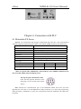
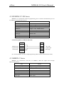
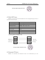
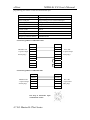
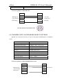
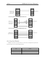
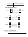
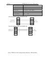
Contents Chapter 1. General Introduction……………...…………………………………………………...3 1.1 1.2 1.3 1.4 Functions……………………………………………………………………………...3 General Specifications………………………………………………………………..3 Names of the Components……………………………………………………………4 Dimensions and Installations…………………………………………………………6 Chapter 2. The Editor TP200…………………………………………………………..8 2.1 General Introduction of TP200………………………………………………………...8 2.1.1. About the Project and Windows……………………………………………...8 2.1.2. Contents of the Window……………………………………………………...8 2.1.3. Flowchart of Using……………………………………………………………8 2.2 Editing the User’s Window……………………………………………………………8 2.2.1 Creating a New Project……………………………………………………….8 2.2.2 Making Basic Window……………………………………………………….10 2.2.3 Configuration of MD204L……………………………………………………11 2.2.4 Text……………………………………………………………………………12 2.2.5 Dynamic Text…………………………………………………………………14 2.2.6 Function Keys (for window jumping)………………………………………..16 2.2.7 Data Display………………………………………………………………….20 2.2.8 Data Setting…………………………………………………………………..23 2.2.9 The LEDs…………………………………………………………………….25 2.2.10 Function Keys (for controlling the status switches)………………………...29 2.2.11 Bar Graph……………………………………………………………………31 2.2.12 Trend Line…………………………………………………………………..32 2.2.13 Alarm List…………………………………………………………………...33 2.3 Saving the Projects……………………………………………………………………35 2.4 Downloading the Projects…………………………………………………………….35 2.5 Importing .TPE Project……………………………………………………………….36 Chapter 3. Manipulation 3.1 Communication……………………………………………………………………….38 3.2 Changing the Windows………….……………………………………………………38 3.3 System Password……………………………………………………………………38 3.4 Changing the data……………………………………………………………………..39 3.5 Controlling the Switches………………………………………………………………40 Chapter 4. Connection with PLC 4.1 Mitsubishi FX Series………………………………………………………………….41 4.2 SIEMENS S7-200 Series……………………………………………………………..42 -1- eView MD204L V4 User’s Manual 4.3 OMRON C Series…………………………………………………………………….42 4.4 Schneider NEZA/TWIDO Series……………………………………………………..43 4.5 Delta DVP Series……………………………………………………………………..44 4.6 Panasonic FP Series…………………………………………………………………..44 4.7 LG Master-K CNet Series…………………………………………………………….45 4.8 The Modbus Protocol of LG Series…………………………………………………..46 4.9 FACON Series…………………………………………………………………………47 4.10 KOYO S Series………………………………………………………………………48 4.11 ECOSTEP Series…………………………………………………………………….49 4.12 AB Micrologix Series……………………..................................................................50 4.13 MODBUS RTU/ASCII………………………………................................................50 4.14 eView Free Protocol......................................................……………………………..51 eView TP200 V4.0.0 Software Release Note……………………………………………………..53 1. 2. 3. 4. 5. ECOSTEP Series……………………………………………………………………...57 AB Micrologix Series………………………………………………………………...58 MODBUS RTU/ASCII………….................................................................................59 eView Free Protocol.......................…………………………………………………..60 Important Notes……………………………………………………………………....63 eView MD204L V4 User’s Manual Chapter 1. General Introduction of MD204L 1.1 Functions MD204L is a Human-Machine Interface that is used with many kinds of PLC (or the other intelligent controllers with communication ports). With MD204L, both the values of the PLC inner registers and the relays status of PLC can be monitored or changed through texts or LEDs. So the operation of the machines or the devices is more easy and convenient. MD204L programmable text monitor has many features: The windows are made with the editor TP200 on PC. Text including Chinese characters can be input and the PLC address can be set. The windows are downloaded with serial port. The PLC communication protocols are downloaded to the MD204L with the data of the windows, so the engineer needn’t program of communication. It can work with most popular PLC, including SIEMENS, Mitsubishi, OMRON, Schneider, FACON, LG, Delta, AB ,SAIA and etc. It supports some general protocols like Modbus RTU, Free communication and ECOSTEP protocol applied in KINCO servo motor driver. Password protecting function. Alarm List function. The current alarm information is displayed one by one. Optional clock module is available. They can provide a real-time clock. It has 20 keys, which can be defined as function keys,there is a keyboard for numeric input. The manipulation is simple. Some of the mechanic buttons on the controlling cabinet can be substituted with them. Various communication modes can be selected. Any of RS232, RS422 and RS485 is OK. STN LCD with background lights. 4 rows (24 western or 12 Chinese characters in every row) of characters can be displayed at the same time. The front panel of the MD204L accords with IP65 standard. It is waterproof and greaseproof. 1.2 General Specification Electric Specification WARNING: The product may be damaged if the input voltage is out of range or the positive and negative poles are connected incorrectly. Input Voltage DC12V-DC24V Power Consume Max. Power Cut Time Max. Voltage Insulative Resistance ≤4W (TYP2.0W) ≤20ms AC1000V-10mA 1min.(between signal and GND) DC500V-about 10MΩ (between signal and GND) Ambient Requirement Operation Temperature 0~50℃ eView MD204L V4 User’s Manual Storage Temperature Ambient Moisture Vibration Resistance Interference Resistance Atmosphere Protection Structure –10~60℃ 20~85%(no condensation) 10~25Hz(Max. 2G for 30 min. in any of the X,Y,Z axis) Voltage Noise: 1000Vp-p No corrosive gas IP65F 1.3 Name of Components On the front panel of MD204L, there is a LCD display and 20 thin film switches. The keys have a good touch feeling, and they are endurable and reliable. Besides being used for the basic functions, all the 20 keys can be set to execute specific functions, for example: jumping the windows directly or setting the status parameters etc.. The front panel of MD204L programmable text monitor is shown as following picture: All the 20 function keys can be defined to execute specific functions, for example,Bit setting,Bit resetting ,window jumping etc.. For the undefined keys can only execute basic functions including setting the registers, returning to the initial window and jumping from the current window to the previous/next window. The basic functions of the function keys: KEY [ESC] BASIC FUNCTION When pressed, the MD204L will return to system initial window. The user can designate the system initial window during the window making procedure (default value is window no. 1, window no.0 is prohibited). Usually the Main Menu window or the most-frequently-used window is set to be the initial window. [ALM] When pressed, the MD204L will shift to the predefined alarm list information window. It can also be defined as a specific function key. [CLR] When pressed in the process of data input(you must press [SET]first),you can input data with numeric keyboard directly,need not shift key[<-] [->] [←] [→] Left shift the digit being edited when changing the register data. When pressed, the digit twinkling will be shifted to the left one. Right shifting the digit being edited when changing the register data. When pressed, the digit twinkling will be shifted to the right one. eView MD204L V4 User’s Manual Jump to the previous window. The number of the previous window is designated in the Window Attribute option (default value is the result of subtracting 1 from the current window number). In the data setting mode, pressing it can add 1 to the digit being edited. The value will increase from 0 to 9, then return to 0…… [↑] Jump to the next window. The number of the next window is designated in the Window Attribute option (default value is the result of adding 1 to the current window number) In the data setting mode, pressing it will subtract 1 from the digit being edited. The value will decrease from 9 to 0, then return to 9…… [↓] [SET] [ENT] Press it to enter the mode for editing the value of registers. The register being operated is displayed in reverse color. The digit being edited is flickeringly displayed. If the current window contains no register setting components, no operation will be executed. When [SET] is re-pressed before [ENT] is pressed, the edition done to the current register will be canceled. The user can continue to operate the next data register. NOTE: The function of register setting for [SET] can NOT be disabled by the user-defined function. When password protection is enabled, pressing it will pop up a window for password setting. In register setting mode, pressing it means the edition on the current register is finished. The edited data will be saved. Then the edition will move to the next register. After the edition on the last register on the current window has been finished, it will quit from the register setting mode. NOTE: Except for the [SET] key, if there is a conflict between the basic function and the user-defined function for the same key, the basic function will be disabled. The basic function of register setting for [SET] has the highest priority. Although it can be defined to execute other functions, the register setting function will not be disabled. So if it is necessary to execute the function for setting register, please don’t define [SET] for other functions. There is a power supply port, a COM port and a contrast adjusting potentiometer on the two sides of MD204L. On the left side of the product (back view), there is a DC power supply port and a 9-pin eView MD204L V4 User’s Manual D-shape male socket as the COM port. The RS232, RS485 and RS422 COM port is built in the 9-pin D-shape socket. To download the window data, connect the 9-pin port of MD204L and the 9-pin port of PC with the communication cable MD2-PC. To communicate with PLC, select the proper connection mode in the configuration software according to the type of the PLC. To adjust the contrast of the display, turn the contrast adjusting potentiometer on the right side of MD204L (back view) with a small screwdriver. The display of MD204L is equipped with a LED background light. When any key is pressed, the light will turn on. In default conditions, the light will turn off automatically if there is no operation in 3 minutes(default set). Pin Definition of the Serial Port of MD204L: PIN DEFINITION 1 TD+ 2 RXD 3 TXD 4 NC 5 GND 6 TD- 7 RTS 8 RD- 9 RD+ MD2-PC Connection Guide: MD204L(9PIN Female Plug) PC(9PIN Female Plug) RXD 2 2 RXD TXD 3 3 TXD RTS 7 7 CTS GND 5 5 GND 1.4 Dimension and Installation Guide Dimension of MD204L (L*W*H): 172*95*30 (mm). Dimension of the hole for installation is showed in the following figure: eView MD204L V4 User’s Manual Four ferric installation screws are included in the accessory package of MD204L. There are four rectangular holes for fixing the MD204L on the two sides of the MD204L, two on the top and two on the bottom. Fix the MD204L in the hole on the controlling cabinet with the screws. The procedure is listed here: Make a rectangular hole on the front panel of the controlling cabinet according to the dimension in the figure above; Put the MD204L into the hole, with the front side facing to the out side; Insert the screws into the fixing hole on the flanks of the md204l and fasten them; Connect md204l and the COM port of PLC with a cable. The cable can be provided by the manufacturer of the MD204L or be made by the user according to the Connection Guide provided in this manual. Switch on the 24-V DC power supply to start the system. eView MD204L V4 User’s Manual Chapter 2. The Editing Software TP200 2.1 General Introduction of TP200 TP 200 V4.0.0 is the specific configuration software for the programmable text monitor MD204L V4. It can run on the WINDOWS 98/2000/XP platforms. It is easy to study and convenient to use. The user can input English/Chinese characters directly. 2.1.1 About the Project and Window The basic element of a project is the window. All the windows for one certain project are saved in a single project file. Every window is made to execute some certain functions. By arranging the windows, the user can jump from one window to another. The application project file is composed of all the windows. 2.1.2 Window Contents After opening a project, the user can “new” or “open” a window. The user can put some elements such as characters (English or Chinese), LEDs, switches, data inputing boxes and jump keys on every window. Jumping between different windows is allowed. The operator can carry on the operations such as data monitoring, parameter setting, switch controlling and alarm list monitoring. 2.1.3 Flowchart of Using The basic flowchart of using is shown in the following figure: Software installation Run Run the software Download the windows Create or Open a project Create or Open a window Save the project Edit the window 2.2 Editing the User’s Window 2.2.1 Create a New Project Run the software TP200 and create a project, after which a window editor will be showed on the screen. eView MD204L V4 User’s Manual On the top of the editor, there is the menu and the toolbar. The window numbers and window descriptions are listed in the table on the left of the editor. Window: List the serial number of all the windows included in the project. It is helpful for finding the window quickly. Description: A simple description of the window function. The window-editing region is on the center of the editor. There is a grid of white dots in the display region. The distance between every two rows and two columns is 8 points. The whole region is a matrix of 192*64 points. The user can refer to the dots nearby to align the components when laying or moving them. If the user move a component by dragging it with the cursor, each time the component will move across the distance which is a multiple of 4 (for example, 4,8,16……). When necessary, change X and Y positions of the components to locate them in arbitrary positions. The table below is the description of all the buttons in the toolbar: Button Function Create a new project Open project Save project Cut the text in the textbox, also can be used to delete components Copy the text in the textbox eView MD204L V4 User’s Manual Paste the text to the toolbox New window, pressing the key “New” in the window indicator will also new a window. Change a window with the copy of another one Delete the current window Designate the initial window. When the MD204L is running, the system will return to the initial window directly if [ESC] is pressed. Usually the main menu or the window most-frequently used is set to be the initial window; Set the system password; Set the definition number of the interactive controlling register. Login the Alarm List information. Every piece of information represents a status of the select variable. Download the project to MD204L through the RS232 port on PC. Press or activate [File]->[New Project] command in the menu to pop up a dialog box for PLC selection: Select the proper PLC type, baud rate, data bits, stop bits and parity in the dialog box. Select the PLC type according to the object that is connected with MD204L. The window data and the protocol corresponding to the selected PLC will be downloaded to MD204L monitor when execute the window downloading function of TP200. MD204L will communicate with PLC after the protocol loaded. 2.2.2 Making Basic Window In the example given below, the PLC type is Mitsubishi S series. The example will give you a general description of window making. eView MD204L V4 User’s Manual Firstly, enter the system initial window (default value is window no.1) editing mode. The properties of the current window (window no.1) are shown at the right and bottom edge of the interface. Every window has its own properties, which include three items: Window Description: Descript the use of the window. It helps the designer to note the use of all the windows. (can be omitted),for example:“main menu” When Up Arrow key ([▲]) pressed, jump to window: The number of the window that it will jump to when Up Arrow key pressed. When Down Arrow key ([▼]) pressed, jump to window: The number of the window that it will jump to when Down Arrow key pressed. The most convenient way for window jumping is to press [ESC], [▲] and [▼] when the MD204L is running. The user can also jump from one window to another by pressing the user-defined function keys. Note: If the [▲] and [▼] key in the current window are defined for other functions, the window jumping parameters of the window properties are invalid. If the window designated by the [▲] key doesn’t exist, the system will search up until the existing window is found and jump to it. It will stop at window 1 if no window is found. The situation of the [▼] key is similar, that means the system will search down for the window if the designated one doesn’t exist.. If there are some data setting components in the window, [▲] and [▼] key will execute the function of value increase and decrease in the data setting mode. After quitting the data setting mode, the [▲] and [▼] key will execute the basic function for window jumping. 2.2.3 Configuration of MD204L Press or activate [Tools]->[MD204L config] command to pop up a dialog box for configuring the system parameters of MD204L: Initial Window eView MD204L V4 User’s Manual The first window will be displayed after power on. Usually this window is set to be the main menu window or the most-frequently-used window. Press [ESC] when the MD204L is running, the system will jump to this window directly. Password All the windows of a project share a common password. When the “Password” attribute of the components such as data setting window, function keys and etc. is enabled. The components can only carry out their functions when the system password is entered. With this function, the user can hide the windows and secure the data. The password operation is discussed in the following text. Note: Password is valid only when there is a component whose password attribute is enabled in all the windows of the project. The password can be an arbitrary integer between 0 and 9999. Screen Saver Under default conditions, the backlight will hold for 3 minutes. The time can be set by the user. If it is set to be “never”, the backlight will keep on. Also, the window can be set to jump to a screensaver window when no key is pressed in 3 minutes. Note: If the window has jumped to a screen saver window, the pressing of any key will not carry out any function. Any operation will awake the screen saver to return to the original window. Only text or picture component can be used as screen saver. Dynamic components such as register and bar graph can’t be used as screen saver. MD204L Status Control Usually the window changing is executed by pressing the keys. Besides, the PLC can change window by changing the data in register. If this property is selected, the number ‘n’ will be written into the D300(for example) controlling register at the beginning of running, then MD204L will jump to window No.n. After jumping to that window, the data in D300 controlling register will be cleared. MD204L write the current window no. into D301, so PLC can know the status of the status of MD204L. Note: The user can define the address of the interactive controlling register. MD204L Peripheral Control If necessary, the user can contact to the manufacturer to get an optional clock module. When a clock module being used with MD204L, the system will transmit the data of the clock to the controlling register defined by the user. Note: The user can define the address of the interactive controlling register. 2.2.4 Text The table below describes the functions of the 8 components on the top of the window editing box: Component Function Input text, including Chinese characters and English letters. eView MD204L V4 User’s Manual Dynamic text list. The content of the text can be changed under the control of PLC register. Register components. The user can dispose some data setting/monitoring components with it. (the relate address are the PLC registers) LED indicator. Indicate the on/off status of the inner delays in PLC. Function key. The 8 keys at the lower part of MD204L and the other 12 keys for number input can be defined to be function keys. They can execute the functions such as window jumping and switch control. Bar graph. Monitor the data change in PLC in the form of bar graphs. Trend line. Monitor the data change in PLC in the form of trend lines. Paste pictures. Paste a monochrome BMP picture (Max. 192×64 pixels) onto the window. The example below shows how to design a main menu window as the window no.1. Firstly, lay the text “Main Menu”. Press and click the left button on the editing region to affirm the operation (right click will cancel it). After left click, the default text “text” will be displayed in the editing region. The properties of the text are displayed below the editing region. The text string will move as the user moves the cursor. The distance across is a multiple of 4 points. To locate the text in an arbitrary position, edit the X and Y coordinates. Position X value represents the horizontal position of the text string. Y value represents the vertical position of the text string. eView MD204L V4 User’s Manual The origin of the position is the up-left corner of the window. Style Double: The text will be displayed in double size, both horizontally and vertically. Reverse: The text and the background will be displayed in reversed color. Text Strings The content that will be actually displayed is input here. The user can input English letters or Chinese characters with various kinds of Chinese input methods in this textbox. The content in it can be copied or pasted. Example: Display the text “text” in reverse color. Input “text” in the text string box and select the “Reverse” checkbox. 2.2.5 Dynamic Text Press and click the left button on the editing region to affirm the operation (right click will cancel it). After left click, the default text “Dynamic Text” will be displayed on the editing region. The properties of the dynamic text are displayed below the editing region. The text string will move as the user moves the cursor. The distance across each time is a multiple of 4 points. To locate the dynamic text in an arbitrary position, edit the X and Y coordinates. eView MD204L V4 User’s Manual Position X value represents the horizontal position of the text. Y value represents the vertical position of the text. The origin of the position is at the up-left corner of the window. Style Double: The text will be displayed in double size, both horizontally and vertically. Reverse: The text and the background will be displayed in reversed color. Register The PLC data register for controlling the status change of the dynamic text. Mode Determine the data form of the data register. The form will affect the display form of the numeric items in the dynamic text. Display Text Log the different text content corresponding to different values of the data register. It can keep the texts corresponding to as many as 32 different statuses. Example: Display the dynamic text controlled by register D10. The dynamic text to be displayed has three statuses: “In gear”, “Temp. Lower” and “Position arrived”. The three texts correspond to the D10 register value 2a, 30e and d43f (HEX form) respectively. Input “2a” in the “Value” space of the first row and “In gear” in the “Context” space on the right. Input the other two statuses in the same way. If the value of register D10 is 2a, the dynamic text be displayed is “In gear”. If it is 30e, “Temp Lower” will be displayed. Other conditions can be inferred from the two examples above. The example is shown in the figure below: eView MD204L V4 User’s Manual 2.2.6 Function Keys (for window jumping) Next, configure the function keys in the main menu window to execute the function of window jumping (for example, press [<] to jump to the parameter setting window; press [>] to jump to the mode setting window). The procedure of defining the function keys is: Press to activate a dotted rectangular box. The box moves as the cursor moves. Click the left button to determine the position of the function key. A hand shape and the function key to be defined (default key is [>]) are displayed in the editing region. The properties of the function key are displayed below the editing region. The meanings of position and style are the same as those in the text property. They indicate the position,the size and the color of the graph. The function key setting window is shown in the figure below: eView MD204L V4 User’s Manual Key Select a proper key from the 20 keys. Hand For the convenience of use, add a hand shape symbol before the key symbol. The hand indicates that pressing the key will carry out an operation. The user can remove the hand shape to save the space. Invisible The user can make the symbols of some keys invisible in the window. But the functions of those keys are still valid. Password Only when the system password is entered correctly, the function key can execute its function. Set Coil The function key is defined to set a switch. Jump to The key is defined to execute the window jumping function. Set Register The key is defined to set the register parameters. Station No. The station number of PLC Type When the key is defined to set a switch, the definition number of the PLC relay corresponding to the switch is determined by the type here. Addr Set the address of the relay. ON Set the designated relay on. eView MD204L V4 User’s Manual OFF Set the designated relay off. Reverse Set the designated relay to be of negative logic. Instant on The designated relay will be set on when the key is pressed down. When the key is released, the relay will be set off. Click the down arrow on the right of the list to show the names of the 20 keys. Select the proper key to be defined. To make the window simple, the hand shape can be removed by not selecting the checkbox “Hand”. So only the keys are shown on the screen. Select the option button “Jump to” to define the key as a window jumping function key. Designate the target window number below the key. If the number is 10, it means window no.10 is the parameter setting window. To hide the parameter setting window, select the checkbox “Password” to enable the password property. Thus the system will jump to window no.10 only when the system password is eView MD204L V4 User’s Manual entered correctly. After setting the function key, put the text “set parameter” beside the key symbol to inform the operator that it will jump to the window for parameter setting when [>] is pressed. Put the symbol of [<] and the text “Set status” in the editing region to indicate that it will jump to the window for status setting when [<] is pressed. The user can set window no.20 to be the parameter-setting window. Note: To leave some margin for inserting new windows, the number of different kinds of windows should be non-continuous. For example, if it is necessary to insert another parameter-setting window, it can be set to window no.11, just after the original parameter-setting window. Add a key for jumping to the alarm window on the main menu. So it will jump to the alarm list window when that key is pressed. eView MD204L V4 User’s Manual For logging the alarm information, see 2.2.13. Setting register parameter with a single function key To write a parameter (constant) to a designated register, select a function key from the key list and select the option button “Set parameter”. The constant parameter will be written to the designated register when that key is pressed during running. Setting as the following figure will write the hexadecimal number 7FFF to the D register at address 0. 2.2.7 Data Display This section will introduce how to make a Set parameter window. The methods of setting the components such as parameter display, parameter setting and password setting are discussed in detail. Example: The window no.10 sets and monitors three couples of parameters, which are corresponding to the output of group A, B and C respectively. The current values are in the left column, while the target values in the right one. The current values can be used to monitor the data only, while the target values can be used for both monitoring and changing the data. The relation between the parameters and the PLC data registers are given in the table below: eView MD204L V4 User’s Manual Addr. of the current values Addr. of the target values Output of Grp.A D100 D110 Output of Grp.B D101 D111 Output of Grp.C D102 D112 The procedure of making the window: Click [New] to pop up a dialog box for setting the window number and the window description. Window No. The serial number of the new window. Window Description Descript the character of the new window. Set the window number to be 10 and input the window description “Set parameter”. Click [Ok]. The window properties are displayed at the right and bottom edge of the interface. Set the destination window number of [▲] to be 0 and that of [▼] to be 20. So when it is not in the data setting mode, it will jump to Main Menu if [▲] is pressed and to Set parameter if [▼] is pressed. Put the text “Current”, “Target”, “A Output=”, “B Output=” and “C Output=” in proper positions in the editing region. eView Put the data display boxes. Press MD204L V4 User’s Manual to show a rectangular dotted box moving with the cursor. Click the left button in the proper position. The number “12345” in the dotted box indicates that this component is a five-digits register displaying/setting box. The properties in the dialog box are: Station The definition number of the PLC register corresponding to the display component. Register It is the amount of the registers being displayed or set. The minimum number is 1, and the maximum is 2. Password If selected, the data can be changed only when the correct system password is entered. The command for setting the password is in the menu “Tools(T)”. Digits The maximum number of digits of the data being displayed or set Decimal The length of the significant digits behind the decimal point Dec. The data in the register will be displayed in decimal form. (Recommended for Mitsubishi and OMRON ) Signed Only valid when the “Dec.” mode is selected. If the highest digit of the register is 1, the eView MD204L V4 User’s Manual data will be displayed as a negative number. For example, the hexadecimal number FFFEH represents –2. HEX/BCD The data is displayed in hexadecimal form. (Recommended for KOYO(S) PLC) Set The component can be used for setting data if it is selected. So the component can be used for both monitoring and setting the data. The register set box has some special properties: maximum, minimum and password. In this example, the settings are listed below: Register type=D; Addr=100; Register=1; Digits=4; Decimal=0; Mode=Dec.; the negative number will not be displayed. Set the display boxes of the current output of group B and C in the same way. The register addresses are D101 and D102. The other properties are the same as those of group A. 2.2.8 Data Setting Continue the configuration of the parameter-setting window. Press to show a dotted box moving with the cursor. Move the cursor until the proper position is reached, then click the left button to confirm the position. Select the “Set” checkbox. So the component has the function of monitoring and setting the data. eView MD204L V4 User’s Manual If the “Set” checkbox is selected, two additional options, “Password” and “Limited”, are enabled. Password To enhance the security of the device, the operation of parameter setting can be protected by password. To set or change the password, activate the command “Tools”-> “MD204L config” to pop up a dialog for password setting: Enter a new password or change the original password, for example, “5678” and click “Ok”. When the operator press the key [ENT], the MD204L will pop up a password enter window. The data can be changed only when the operator enter the correct password. All the windows of one project share a common password. Limited The designer can set limits to the data to make the data out of limits invalid. Thus the eView MD204L V4 User’s Manual possible damage done by inputting data too great or tiny is avoided. For example, let the maximum input be 9000 and the minimum be 0. The setting value will be written into the register only when it is between 0 and 9000, or the system will halt until a correct value is entered. Original and Project data After selecting the “Limited” checkbox, the designer can select the original data or the project data from the list. Original data The original data option means that the data in the register will be displayed without any operation. The position of the decimal point is determined by the value of the “Decimal” property. For example, if “Decimal”=2 and the register value is 14561, it will be displayed as 145.61. Project data This option means that the data read from the register will be converted to project data before being displayed. The conversion is done following the formula below: The Converted Data= Eng. Min + (original register data – Min Input) * (Eng. Max – Eng. Min) / (Max Input – Min Input) For instance, the data stored in the register is the binary output of a 12-digits A/D, while the data being actually displayed is a voltage between –10000mV and 10000 mV. Do the setting like this: Max Input: 4095 Min Input: 0 Eng. Max: 10000 Eng. Min: -10000 In this way, the result of A/D conversion in the register is displayed as the voltage value. Note: Because of the limited accuracy of floating point operation, there may be some errors in the conversion result. Engineering Limits The maximum and minimum of the project data 2.2.9 LED The procedure for making the Set status window and the method of setting LED and function keys are introduced in detail in this section. Example: the window no.20 is the window for setting the working mode of the machine: manual or automatic. In manual mode, the direction of the movement of the machine (forward or backward) is controlled by pressing the keys on the front panel. The LED indicates the direction of eView MD204L V4 User’s Manual rolling. The relation between the relay statuses and the actions is listed in the following table: Relay status action M10=1 Manual mode M10=0 Automatic mode M20=1 Move forward M21=1 Move backward M20=0 ,M21=0 stop The procedure of window is given below: Press [New window] to pop up the dialog box of window number and window description. Set the window number to be 20 and input the window description Set status. Click [Ok]. The window properties are displayed at the right and bottom edge of the interface. Set the destination window number of [▲] to be 0 and that of [▼] to be 20. So when it is running, it will jump to Main Menu if [▲] is pressed and to Set status if [▼] is pressed. Press to put a LED. There is a dotted box moving with the cursor in the editing region. Click the left button in the proper position to locate the LED. eView MD204L V4 User’s Manual The definition number of the coil 线圈定义号表示指示灯对应 shows the PLC switch address PLC 开关量地址 corresponding to the LED 种类有圆形和方形 2 种 Two kinds of LEDs: round and square 正/负逻辑表示常亮/常灭 Positive/Negative Logic indicates that the LED is on/off for the TRUE status Coil Station No. The definition of the PLC intermediate relay that is corresponding to the LED Shape The shape of the LED, round and square. Positive Logic The LED is filled when the corresponding intermediate relay is ON. Unfilled when the corresponding intermediate relay is OFF. Negative Logic The LED is unfilled when the corresponding relay is ON. Filled when is OFF. Set the coil station No. to be M10; select square shape; select positive logic. There is an unfilled square LED in the editing region. eView Press MD204L V4 User’s Manual to put the function key. There is a dotted box that moves with the cursor in the editing region. Move the cursor and click the left button in the proper position to locate the key. Select the function of the coil Coil properties include station No. and the types of the key actions Select [SET] to be the key for setting the Auto Mode. Set the type and station No. to be M10; select “ON” as the type of key action; remove the hand shape to make the window simple. Put the text “Auto” to the right of the key to indicate that the function for this key is to select the auto mode. Set the Manual key and the Manual mode LED in the same way. The corresponding address of the LED is still M10; select negative logic in the display column. The designated key is [ENT], whose function is to set the relay M10 OFF. eView MD204L V4 User’s Manual Add two round LEDs of positive logic to monitor the moving status of the machine. The addresses of the two LEDs are M20 and M21. The left one is on when the machine is moving forward, while the right one is on when it is moving backward. 2.2.10 Function Keys (for controlling the status switches) Press to put the function key. Select [►], whose corresponding address is M20. the function of the key [►] is to set the relay M20 ON instantly. Retain the hand shape on the window. When [►] is pressed, the M20 relay of the PLC will be set ON, and the machine begins to move forward (program the PLC to designate M20 relay as the trigger of Y0); when [►] is released, the M21 relay of PLC will return to OFF, and the machine stop the forward movement. eView Press MD204L V4 User’s Manual . Select [◄], whose corresponding address is M21. The function of [◄] is to set the relay M21 OFF instantly. Retain the hand shape on the screen. When [◄] is pressed, the relay M21 of PLC is set ON, and the machine will begin to move backward (program PLC to designate the relay M21 as the trigger of Y1); when [◄] is released, the relay M21 returns to OFF, and the machine will stop its backward movement. Put the text “Pos.” and “Neg.” to indicate the forwardness and backwardness of the movements. eView MD204L V4 User’s Manual 2.2.11 Bar Graph The bar graph can give a direct view of some analog parameters such as flow rate, pressure and level. The user can set the height, width and the direction of it arbitrarily. Press to show a dotted box that moves with the cursor. Move the cursor to the proper position and click the left button to locate the bar graph there. Register Address The address of the register corresponding to the bar graph High The register value corresponding to the full bar graph Low The register value corresponding to the empty bar graph Direction The direction of the bar graph, including four options: up, down, left and right. Size The height and width of the bar graph eView MD204L V4 User’s Manual This bar graph can be used to monitor the data in register D300. The bar graph is full when the value of D300 is 100. When the bar is filled 50%, the value of D300 is 50. 2.2.12 Trend Line Some parameters in industrial control applications vary at a slow rate. Often, the operators want to know the variations of these parameters in a certain of time. Trend line should be the best choice. Press to show a dotted box that moves with the cursor. Move the cursor to the proper position and click the left button to locate the trend line there. eView MD204L V4 User’s Manual Register Address The address of the register corresponding to the trend line High The register value when the trend line reaches the 100% of the scale Low The register value when the trend line reaches the 0% of the scale Data Sample (number of dots) The total of the sample points in the whole trend line. The more sample dots does the trend line has, the more detail it can provide. Certainly more sample dots make the time period longer. Sample Interval The interval between two sample points Size The length and width of the trend line Note: A trend line component can display only one line. 2.2.13 Alarm List In industrial auto-control applications, alarming is a very important function. It can be used in many cases. Alarm list is the most direct and simple method. Every project of MD204L can have a cluster of alarm list information. Every piece of information corresponds to a relay. The addresses of all the relays are continuous. The user can designate the initial address of the relays. When any of the relays jumps from OFF to ON, the corresponding alarm information is activated. MD204L will pop up the alarm window, where the alarm information is displayed in the first row. If another relay jumps to ON, the new information will be displayed in the second row. When some alarm relay jumps to OFF, the corresponding alarm information will disappear automatically. To log the alarm information, press to pop up the alarm list dialog box: The list is blank for no information has been logged. Move the cursor to the “Alarm description” column and enter the information “Temp. over high”. Press “Enter” to show the screen as the following figure: eView MD204L V4 User’s Manual Input other information in the same way. After entering all the information, set the coil type and address to M100 (for example) to indicate that the relays M100-M102 correspond to three pieces of alarm information. eView MD204L V4 User’s Manual When MD204L is in gear, if M101, M101 are set ON, it will pop up an alarm window and display as the figure below shows: Seeing this alarm window, the operator can take some measures to solute the breakdowns. To return to the monitoring window, press [ESC]. 2.3 Save Project After the window editing is finished, the project files can be saved and downloaded to MD204L for shakedown test. Press to show the save dialog box: eView MD204L V4 User’s Manual Select the proper path and filename to save the file. The system defines “evp” as the default external filename. Enter the filename and select the proper path, then click “Save”. 2.4 Download Window Connect the 9-pin RS232 serial port of PC and that of MD204L with the window downloading cable MD2-PC. Make sure that MD204L is connected with a 24V DC power supply. Press to begin the download process. A dialog box will be displayed to indicate the progress of downloading: After all the transmission has been done, a dialog box will pop up to indicate that all the project windows have been downloaded to MD204L. Cut off the power of MD204L and remove the window downloading cable MD2-PC. Connect MD204L and PLC with the PLC communication cable. Turn on the MD204L and PLC. If the communication is successfully established, the system can be used for data monitoring and other functions. If there are some communication failures due to the incorrect communication parameters or some errors in cable connection, the MD204L will show the text “communicating” at the bottom of the right edge, to indicate that MD204L is trying to establish the connection with PLC. If the MD204L can’t communicate with PLC, please check the items in the list below: Is the PLC type selected in the project the same as that of the PLC being actually eView MD204L V4 User’s Manual connected to? Are the addresses of the PLC register or coil visited in the project out of range? Is the station number of PLC correct? Are they connected with a communication cable? Is the connection of the cable correctly done? Are the PLC communication parameters configured correctly? Are the power supplies for PLC and the MD204L OK? Are they power on? Contact the seller if the problem can’t be solved. 2.5 Importing .TPE Project This configuration software is version V4.0.0 of TP200. Because the hardware is updated with the software, the configuration software supports only the new MD204L V4. The projects based on the old version product can be converted through “Import .TPE Project”. After conversion, the project can be downloaded to MD204L V4. As the figure above shows, select “File”-> “Import .TPE Project” to open a TP200 old version project file with the postfix “. TPE”. eView MD204L V4 User’s Manual After selecting a file, the program will show a progress bar: Click “Convert” to start the conversion. The program will do the conversion automatically and save the converted old version project file with the postfix “. EVP” in the current directory of the old version project. For instance, an old version project named “unnamed. TPE” will be converted to “unnamed. EVP”. The user can select the “Save Project As…” command to save the converted project to a designated directory. The current directory can be seen on the top of the window. Chapter 3. Manipulation 3.1 Communication When the window downloading has finished, cut off the power supply and remove the downloading cable MD2-PC. Connect MD204L and PLC with a communication cable and check the setting of the PLC communication parameters. Turn on the power supply (24V DC for MD204L), the MD204L then start to work. Note: MD204L can work whether the PLC is running or being programmed. 3.2 Shifting the Windows Take the project windows edited in chapter 2 as an example to introduce the manipulation of MD204L. MD204L displays window No.1 at first. (Because the initial window is window No.1.) Window No.1 is a main menu window. Pressing the function keys can jump to sub-windows. Press [►] to jump to parameter-setting window (window No. 10). The data in the left column are the outputs of the three groups, corresponding to PLC eView MD204L V4 User’s Manual addresses D100, D101 and D102 respectively. 3.3 Password Password must be entered before changing the data. Press [ENT] to show the window below: Select 1 with the [▲],[▼] and [ENT] keys to log in; select 2 to log out; press [ESC] to return to the monitoring mode. Select 1, the window will be like the figure below: Input the password with the number keys, the number input will be displayed as “*”. Press [ENT] when the password has been input. If the password is correct, it will show the window below: If the password is incorrect, it will show the window below: Select 2 to log out, it will show the window below: 3.4 Changing the data eView MD204L V4 User’s Manual Log in and press [ENT], the target output of group A is flickering. So the data that will be changed first is the target output of group A. Press [CLR] to clear current value and input the new value with the number keys. If it is necessary to input a signed number, press [+/-] to change the sign. To input the hexadecimal number A-F, press [◄] and [►] to change the digit being edited. Press [▲] and [▼] to change the value of that digit. The value will vary in the sequence 9-A-F-0. Press [ENT] to confirm the entered data. The data been changed is written into the PLC register D110. The target output of group A will stop flickering, while that of group B starts to flicker. That means the setting for group A has been done and the setting for group B begins. To quit or skip the setting for group A, continue to press [SET]. The output of group A will remain the original value and stop flickering, and the output of group B starts to flicker to indicate that the data being changed is B output. When the C output has been set, all data will be normally displayed, none of them flickering. To enter the setting mode again, press [ENT]. 3.5 Controlling the Switches After changing the parameters, press [ESC] to return to the initial window (window No. 1) as the figure below shows: Press [◄] to jump to the status-setting window. The device is in manual mode at this time. Press [SET] to change to auto mode. The relay M10 of PLC is set ON. Press [◄] and hold, the machine will continue moving forward; press [►] and hold, the machine will move backward continuously. eView MD204L V4 User’s Manual Chapter 4. Connection with PLC 4.1 Mitsubishi FX Series MD204L can communicate with all types of Mitsubishi FX series PLC. The communication is done through the programming port of PLC or the FX2N-422BD module of the FX2N series. Item Content MD204L COM port 9-pin COM port PLC COM port Programming port or FX2N-422BD Default parameters 9600bps、7bits、1stop、Even Station No. 1 Distance (Max.) 70m Comm. mode RS422 / programming port MD2-FX2N Cable type PLC type FX0S FX0N FX2N Inner relay address M000-M511 M000-M511 M000-M511 Register parameter address D00-D31 D000-D255 D000-D511 Must use special cable “MD2-FX2n” which made by eView HMItek (Shenzhen) Ltd. (also for FX0S, FX0N, FX1S and FX1N Series) Pin map of 8-pin round female socket (Note that the right-left direction of the male plug is reverse to that of the female socket) Note: Because the communication port of the Mitsubishi FX2N series PLC has been upgraded, the client has to use the MD2-FX2N cable provided by us or the SC09 programming cable provided by Mitsubishi to ensure the communication between MD204L and FX2N PLC successful. eView MD204L V4 User’s Manual 4.2 SIEMENS S7-200 Series MD204L can communicate with the programming port or external communication port of S7-200 PLC through the PPI protocol. Item Content MD204L COM port RS485 COM port PLC COM port Programming port or external COM port Default parameters 9600bps、8bits、1stop、Even Station No. Range:2-126,default value: 2 Distance (Max.) 100m(twisted pair wire) Comm. mode RS485 Cable type MD2-S7-200 Inner relay address M000-M317 Register parameter address VW000-VW4096 Connection guidance of MD2-S7-200 cable 1 TD+ MD204L side 9 RD+ 3 A PLC side 9-pin D-shape female plug 6 TD- 8 B (9-pin D-pin male plug) 8 RD- (It is recommended to use the S7-200 programming cable to be the communication cable.) 4.3 OMRON C Series MD204L can communicate with PLC of OMRON, CPM and CQM series through HOST-Link protocol. Item Content MD204L COM port 9-pin communication port PLC COM port Programming port or external COM port Default parameters 9600bps、7bits、2stop、Even Station No. Range: 0-99, default: 0 Distance (Max.) 15m Comm. mode RS232 Cable type MD2-CQM eView MD204L V4 User’s Manual Inner relay address IR20000-22715 Register parameter address DM000-DM1024 Note: CPM1A and CQM1-CPU11 has only one COM port, so the signal of the programming port must be converted to RS232 signal with the connection cable or communication module provided by OMRON (CIF01-CAB) when connect with the MD204L. Connection guidance of MD2-CQM cable MD204L side 2 RXD 2 TXD 3 TXD 3 RXD (9-pin D-shape female plug) PLC side (9-pin D-shape male plug) 5 GND 9 GND NOTE:THE CPU MUST WORK ON “MONITOR MODE” 4.4 Schneider NEZA/TWIDO Series MD204L can communicate to the programming port of MODBUS RTU protocol. Item NEZA/TWIDO PLC through 内容 MD204L COM port RS485 port PLC COM port Programming port Protocol Modbus RTU Default parameters 19200bps、8bit、1stop、NONE Station No. 1-147,default:1 Distance (Max.) 100m(twisted pair wire) Comm. mode RS485 Cable type MD2-TWIDO Inner relay address %M000-%M127 Register parameter address %MW000-%MW511 Connection guidance of MD2-TWIDO cable 1 TD+ MD204L side 9 RD+ 1 A PLC side 9-pin D-shape female plug 6 TD- 2 B 8 RD- 5 (8-pin round male plug) 7 NOTE: the relation between HMI and PLC 0X/1————M0 0X/2————M1 4X/1————MW0 4X/2————MW1 …… …… eView MD204L V4 User’s Manual Pin map of 8-pin round female socket 4.5 Delta DVP Series MD204L can communicate with the delta DVP series PLC.The programming port of PLC is used as the communication port. Item Content MD204L COM port 9-pin COM port PLC COM port Programming port Default parameters 9600bps、7bits、1stop、Even Station No. Range: 1-254,default: 1 Distance (Max.) 15m Comm. mode RS232 Cable type MD2-DVP Inner relay address M0-M999 Register parameter address D0-D599 Connection guidance of MD2-DVP cable MD204L side 2 RXD 5 TXD 3 TXD 4 RXD (9-pin D-shape female plug) PLC side (8-pin round male plug) 5 GND 8 GND Pin map of 8-pin round female socket 4.6 Panasonic FP Series MD204L can communicate with Panasonic FP PLC. The communication port is the eView MD204L V4 User’s Manual programming port of PLC or external communication port. Item Content MD204L COM port 9-pin COM port PLC COM port Programming port or external COM port Default parameters 9600bps、8bits、1stop、Odd Station No. Range: 1-32,default: 1 Distance (Max.) 15m Comm. mode RS232 Cable type MD2-FP1, MD2-FP Inner relay address R0000-R875F Register parameter address DT0000-D9999 Connection guidance of MD2-FP1 cable MD204L side 2 RXD 2 TXD 3 TXD 3 RXD (9-pin D-shape female plug) PLC side (9-pin D-shape male plug) 5 GND 7 GND 4 5 8 9 Connection guidance of MD2-FP cable MD204L side 2 RXD 2 TXD 3 TXD 3 RXD (9-pin D-shape female plug) PLC side (5-pin round male plug) 5 GND Pin map of Panasonic 5-pin round female socket 4.7 LG Master-K CNet Series 1 GND eView MD204L V4 User’s Manual MD204L can communicate with the LG Master-K series PLC. The communication port is Port2. Item Content MD204L COM port 9-pin COM port PLC COM port Port2 Default parameters 9600bps、8bits、1stop、None Station No. Range: 0-31,default: 1 Protocol CNet Distance (Max.) 15m Communication pattern RS232 Cable type MD2-LG-CNet Inner relay address M000-M191F Register parameter address D0000-D4500 Connection guidance of MD2-LG-CNet cable MD204L side 2 RXD 7 TXD 3 TXD 4 RXD (9-pin D-shape female plug) PLC side (9-pin D-shape male plug) 5 GND 5 GND NOTE:THE PLC SWITCH SET——1(OFF),2(ON) 4.8 LG Series supporting Modbus protocol MD204L can communicate with the LG series PLC that support Modbus protocol. The communication port is Port2. Item Content MD204L COM port 9-pin COM port PLC COM port Port2 Default parameters 9600bps、8bits、1stop、Even Station No. Range: 1-31,default: 1 Protocol Modbus RTU Distance (Max.) 15m Communication pattern RS232 Cable type MD2-LG-Mod Inner relay address M000-M191F eView MD204L V4 User’s Manual Register parameter address D0000-D4500 Connection guidance of MD2-LG-Mod cable MD204L side 2 RXD 7 TXD 3 TXD 4 RXD (9-pin D-shape female plug) PLC side (9-pin D-shape male plug) 5 GND 5 GND NOTE:THE PLC SWITCH SET——1(OFF),2(ON) 4.9 LG Master-K 120S Programmable port MD204L can communicate with the LG Master-K 120s PLC via Programmable port. Item Content MD204L COM port 9-pin COM port PLC COM port Programmable port Default parameters 38400bps、8bits、1stop、none Station No. Range: 1-31,default: 1 Protocol Programmable port protocol Distance (Max.) 15m Communication pattern RS232 Cable type MD2-LG-Mod Inner relay address M000-M191F Register parameter address D0000-D4500 Connection guidance of MD2-LG-Mod cable MD204L side 2 RXD 3 TXD 3 TXD 2 RXD (9-pin D-shape female plug) PLC side (9-pin D-shape male plug) 5 GND NOTE:THE PLC SWITCH SET——1(OFF),2(ON) 4.10 FACON Series 5 GND eView MD204L V4 User’s Manual MD204L can communicate with FACON MU/MC series PLC. The communication port is Port0. Item Content MD204L COM port 9-pin COM port PLC COM port Programming port Default parameters 9600bps、7bits、1stop、Even Station No. Range: 1-254,default: 1 Protocol FACON communication protocol Distance (Max.) 15m Comm. mode RS232 Cable type MD2-FACON Inner relay address M0000-M2001 Register parameter address R0000- R8071 Connection guidance of MD2-FACON cable MD204L side 2 RXD 2 TXD 3 TXD 1 RXD (9-pin D-shape female plug) PLC side (15-pin D-shape male plug) 5 GND 6 GND 15-pin COM port plug of FACON PLC 4.11 KOYO S Series MD204 can communicate with the KOYO S series PLC. When communicating with SZ-4, either Port1 or Port2 can be used as communication port. Item Content MD204L COM port 9-pin COM port PLC COM port Programming port or external communication port Default parameters 9600bps、8bits、1stop、ODD Station No. Station 1 Distance (Max.) 15m Comm. mode RS232 Cable type MD2-SZ for SZ、SH、SH series MD2-SG for SU、SG series eView MD204L V4 User’s Manual Inner relay address M000-M377 Register parameter address R2000-R3777 Note: All addresses are shown in octal mode Connection guidance of MD2-SZ cable 1 GND MD204L 2 RXD 2 3 TXD 3 RXD PLC side 4 TXD (6-pin) (9-pin D-shape female plug) 5 5 GND 6 GND Pin map of RJ12 6-pin female socket Connection guidance of MD2-SG cable MD204L side 2 RXD 2 TXD 3 TXD 3 RXD PLC side 4 RTS (25-pin) (9-pin D-shape female plug) 5 CTS 5 GND 7 GND 4.12 ECOSTEP Series MD204L can communicate with Kinco ECOSTEP series PLC. The communication port is RS232 port. Item Content MD204L COM port 9-pin COM port PLC COM port RS232 Default parameters 9600bps、8bits、1stop、None Station No. Range: 1-f,default: 1 Protocol ECOSTEP Distance (Max.) 15m Comm. mode RS232/485/422 Cable type MD-ECOSTEP-CAB232/485/422 Connection guidance of MD-ECOSTEP-CAB232 cable eView MD204L V4 User’s Manual MD204L side (9-pin plug) 2 RXD 2 TXD 3 TXD 3 RXD female ECOSTEP side (9-pin) 5 GND 5GND Connection guidance of MD-ECOSTEP-CAB485 cable 1 TD+ 2 RD+ MD204L side 9 RD+ 3 TD+ ECOSTEP side 9-pin female plug 6 TD- 7 RD- (9-pin) 8 RD- 8 TD- 5 GND 5GND Connection guidance of MD-ECOSTEP-CAB422 cable MD204L side 9-pin female plug 1 TD+ 2 RD+ 9 RD+ 3 TD+ ECOSTEP side 6 TD- 7 RD- (9-pin) 8 RD- 8 TD- 5 GND 5 GND 4.13 AB Micrologix Series MD204L can communicate with Allen-Bradley Micrologix series PLC. The communication port is the programming port. Item Content MD204L COM port 9-pin COM port PLC COM port Programming port Default parameters 19200bps、8bits、1stop、None Station No. The station number is fixed on 1 and can not be changed Protocol AB DF1 Distance (Max.) 15m Comm. Mode RS232 Cable type MD2-AB Inner relay address B3/9/10/11/12/13: 0-254 eView MD204L V4 User’s Manual Register parameter address N7/9/10/11/12/13/14/15: 0-254 Connection guidance of MD2-AB cable MD204Lside 2 RXD 7 TXD 3 TXD 4 RXD (9-pin D-shape female plug) PLC side (8-pin round male plug) 5 GND 2 GND Pin map of 8-pin round female socket 4.14 MODBUS RTU/ASCII/EMERSON/RTU EXTEND MD204L can communicate with any slave device that supports MODBUS RTU or MODBUS ASCII. Item Content MD204L COM port 9-pin COM port Default parameters (RTU) 19200bps、8bits、1stop、Even Default parameters (ASCII) 19200bps、7bits、1stop、Even Station No. Range: 1-247,default: 1 Protocol MODBUS RTU/ASCII Distance (Max.) 15m Comm. mode RS232/485/422 Cable type MD2-MODBUS-RS232/485/422 Inner relay address 0X/1X 1-9999 Register parameter address 3X/4X 1-9999 Connection guidance of MD2-MODBUS-RS232 cable MD204L side 2 RXD TXD 3 TXD RXD 5 GND GND (9-pin D-shape female plug) Slave device eView MD204L V4 User’s Manual Connection guidance of MD2-MODBUS-RS485 cable 1 TD+ RD+ MD204L side 9 RD+ TD+ 9-pin D-shape female plug 6 TD- RD- 8 RD- TD- 5 GND GND Slave device Connection guidance of MD2-MODBUS-RS422 cable 1 TD+ RD+ MD204L side 9 RD+ TD+ 9-pin female plug 6 TD- RD- 8 RD- TD- 5 GND GND Slave device NOTE:MODBUS EXTEND SUPPORT 1、4X_BIT(0~F); 2、5X(same as 4X,but for the dword,the high/low word is reversed compare with 4X) 3、6X(support modbus “06” function code) 4.15 MODBUS SERVER MD204L can communicate with MASTER device that supports MODBUS RTU Item Content MD204L COM port 9-pin COM port Default parameters (RTU) 19200bps、8bits、1stop、Even Default parameters (ASCII) 19200bps、7bits、1stop、Even Station No. Range: 1-247,default: 1 Protocol MODBUS SERVER Distance (Max.) 15m Comm. mode RS232/485/422 Cable type MD2-MODBUS-RS232/485/422 Inner relay address 0X/1X 1-9999 Register parameter address 3X/4X 1-9999 Connection guidance of MD2-MODBUS-RS232 cable eView MD204L V4 User’s Manual MD204L side 2 RXD TXD 3 TXD RXD 5 GND GND Master device (9-pin D-shape female plug) Connection guidance of MD2-MODBUS-RS485 cable 1 TD+ RD+ MD204L side 9 RD+ TD+ 9-pin D-shape female plug 6 TD- RD- 8 RD- TD- 5 GND GND Master device Connection guidance of MD2-MODBUS-RS422 cable 1 TD+ RD+ MD204L side 9 RD+ TD+ 9-pin female plug 6 TD- RD- 8 RD- TD- 5 GND GND Master device 4.16 eView Free Protocol MD204L can provide its 255-byte memory as a slave device. Through the free protocol, the 255-bytes memory can be visited for display function. Item Content MD204L COM port 9-pin COM port Default parameters 19200bps、8bits、1stop、None Station No. Range: 0-255,default: 1 Protocol Free protocol eView MD204L V4 User’s Manual Distance (Max.) 15m Comm. mode RS232/485/422 Cable type MD2-FREEPTC-RS232/485/422 Inner relay address M Register parameter address MW 0-254 0-254 Connection guidance of MD2-FREEPTC-RS232 cable MD204L side 2 RXD TXD 3 TXD RXD 5 GND GND Master device (9-pin D-shape female plug) Connection guidance of MD2-FREEPTC-RS485 cable 1 TD+ RD+ MD204L side 9 RD+ TD+ 9-pin D-shape female plug 6 TD- RD- 8 RD- TD- 5 GND GND Master device Connection guidance of MD2-FREEPTC-RS485 cable 1 TD+ RD+ MD204L side 9 RD+ TD+ 9-pin D-shape female plug 6 TD- RD- 8 RD- TD- 5 GND GND Master device 4.17 SAIA PCD S-BUS PROTOCOL MD204L can communicate with SAIA PCD using S-BUS protocol Item content eView MD204L V4 User’s Manual MD204LCOM port 9-pin COM port Default parameters 9600bps、8bits、1stop、None Station No. Range:0-255,default:1,same with PCD station no. Protocol S-BUS Distance (Max.) 15m(RS232) 1200m(RS485) Comm. mode RS232/485 Cable type MD2-SAIA Inner relay address Flag 0-8191 Register parameter address Register 0-4095 Connection guidance of MD2-SAIA-RS232 cable MD204L 侧 2 RXD 3 TXD 3 TXD 2 RXD PCD RS232 接口 (9PIND 型母头) 5 GND 5 GND Connection guidance of MD2-SAIA-RS485 cable 1 TD+ MD204L 侧 9 RD+ D+ PCD 9 针 D 型母头 6 TD- D- RS485 接口 8 RD- eView TP200 V4.0.0 Configuration Software • ReleaseNote eView MD204L V4 User’s Manual TP200 V4.0.0 is a new configuration software for the new version hardware of MD204L V4.0. New type of CPU and greater memory make the new hardware architecture swifter and more stable. TP200 V4.0.0 supports more types of PLC; downloads the configuration faster; provides more useful functions. New hardware supports the importing of old version project, so the user of the old versions can easily use their old projects on the new platform. But for the hardware architectures are different, the new version software can’t be used to download project to the old version MD204L. New Features Configuration downloading is 5-10 times faster than the old version. The program runs faster. Especially when there are many dynamic controls (for example, registers) in the window, the respond speed of keyboard and the refresh speed of display are obviously faster than the old version. Supports more protocols: AB-DF1, ECOSTEP, MODBUS RTU/ASCII,SAIA PCD and more. Dynamic texts are displayed non-continuously. It can display the value of an arbitrary register (<65535). Alarm list can be used with all protocols. The offset in some protocols is no longer required to be 0. Setting the register parameters can be done with a single function key. The register data can be converted to engineering data. Supports the inputing, setting and displaying of hexadecimal number. Supports the enhanced free protocol. As the display unit of the slave device, it can visit the memory of 255 words. The password manipulation is more convenient. Starts and responds faster. Remote upgrade function. When a new version software is available, the user can upgrade the software by downloading the new version from our website. The software of MD204L will be updated automatically during the configuration window downloading. The process of updating will be easily. Compatible with the project of old version TP200. New Functions 1. Non-continuous display of the dynamic texts The dynamic texts can correspond to the register of any data length only the value is less than 65535, the different content will be displayed corresponding to different value of the register. The value can be non-continuous signed decimal numbers or unsigned decimal numbers or hexadecimal numbers. The user can log dynamic texts corresponding to as many as 32 statuses. eView MD204L V4 User’s Manual Example: Display the dynamic text controlled by register D10. The dynamic text to be displayed has three statuses: “Normal”, “Low temperature” and “Position reached”. The three texts correspond to the D10 register value 2a, 30e and d43f (HEX form) respectively. Input “2a” in the “Value” space of the first row and “Normal” in the “Context” space on the right. Input the other two statuses in the same way. If the value of register D10 is 2a, the dynamic text be displayed is “Normal”. If it is 30e, “Low temperature” will be displayed. Other conditions can be inferred from the two examples above. 2. Project Data Conversion After selecting the “Limited” checkbox, the designer can select the original data or the project data from the list. The original data option means that the data in the register will be displayed without any calculation. The position of the decimal point is determined by the value of the “Decimal” property. For example, if “Decimal”=2 and the register value is 14561, it will be displayed as 145.61. The project data option means that the data read from the register will be converted to project data before being displayed. The conversion is done following the formula below: The Converted Data = Eng. Min + (original register data – Min Input) × (Eng. Max – Eng. Min) / (Max Input – Min Input) For instance, the data stored in the register is the binary output of a 12-digits A/D, while the data being actually displayed is a voltage between –10000mV and 10000 mV. Do the setting like this figure shows: eView MD204L V4 User’s Manual In this way, the result of A/D conversion in the register is displayed as the voltage value. Note: Because of the limited accuracy of floating point operation, there may be some errors in the conversion result. 3. Set the register parameters with single function key Select a function key and select the option button “Set Register”. A parameter can be written in to a designated register when the function key is pressed. The following figure shows how to write hexadecimal number 7FFF into address 0 of VW register. 4. Alarm List When the coils are displayed in the form M x.y, the setting of alarm list is shown in the figure below: Coil at any address and offset can be set to the initial coil. 5. Password Password must be entered before changing the data. Press [ENT] to show the window below: eView MD204L V4 User’s Manual Select 1 with the [▲],[▼] and [ENT] keys to log in; select 2 to log out; press [ESC] to return to the monitoring mode. Select 1, the window will be like the figure below: Input the password with the number keys, the number input will be displayed as “*”. Press [ENT] when the password has been input. If the password is correct, it will show the window below: If the password is incorrect, it will show the window below: Select 2 to log out, it will show the window below: 6. Import .TPE project eView MD204L V4 User’s Manual As the figure above shows, select “File”-> “Import .TPE Project” to open a TP200 old version project file with the postfix “. TPE”. After selecting a file, the program will show a progress bar: Click “Convert” to start the conversion. The program will do the conversion automatically and save the converted old version project file with the postfix “. EVP” in the current directory of the old version project. For instance, an old version project named “unnamed. TPE” will be converted to “unnamed. EVP”. The user can select the “Save Project As…” command to save the converted project to a designated directory. The current directory can be seen on the top of the window. eView MD204L V4 User’s Manual New Protocols 1. ECOSTEP Series 2. AB Micrologix Series 3. MODBUS RTU 4. MODBUS ASCII 5. MODBUS RTU EXTENDED 6. MODBUS SERVER 7. EMERSON PROTOCOL 8. SAIA SBUS 9. LG CNET 10. eView Free Protocol MD204L can provide its 255-byte memory as a slave device. Through the free protocol, the 255-byte memory can be visited for display function. Free Protocol: It is a simple communication protocol for connecting the controller with the MD204L. The controller is the master device, and the MD204L is the slave device. To communicate with this protocol, the user only need to write some simple writing/reading programs, and doesn’t need to write the interrupt service routine. eView free protocol is compatible with the old protocols, and it provides a more memory (maximum 255 words) to be visited. The recommended communication parameters are: 19200bps, 8bits, 1stop and none parity. The protocol supports all the setting compounds except those of 7bits. The baud rate range is 1200-115200, the user can select within the range according to the conditions. At first, the controller sends a request to the MD204L. After the MD204L has accepted that request, it will send a response to the controller. The maximum number of words that are exchanged between the MD204L and the controller is 255. They are MW0-MW254. every bit of the words can be used as a coil. The form of the bit is MWx.i(x=0..254,i=0..F). Note that the maximum number of words that can be visited by the protocol each time is 128. If the user wants to visit the whole memory continuously, please visit twice. eView MD204L V4 User’s Manual Form of the Request Station No. Command Address Length [Data] Parity Station No. : The station number of the MD204L (0-255, 0 represents the broadcasting mode, the MD204L needn’t send response) Command: ‘R’ (0x52) represents reading from the MD204Lr; ‘W’ (0x57) represents writing to the MD204L Address: The search number of MW (0-254) Length: The number of MW to be written/read Data: The value of MW, NULL when Command is ‘R’ Parity: Sum up all the bytes from the station number to that before the parity. Divide the sum by 0x100. The remainder is the parity. (Note: if the parity is 0x5a, the check will be skipped.) Form of Response Station No. Status [Address Length Data] Parity Status: The status of the communication : 0 – normal : 1 – address error (address > 254) : 2 – length error (length > 128 or length = 0) : 3 – range error (address + length > 255) : 4 – command error (the command is none of ‘R’(0x52) and ‘W’(0x57) ) When the command is ‘W’ or error value. The gray items (address, length and data) are NULL. Form of Data MWi (High) MWi (Low) MWi+1 (High) MWi+1 (Low) … MWi+n-1 (High) MWi+n-1 (Low) ‘i’ is the address; ‘n’ is the length. At first, the controller sends a request to the MD204L. After the MD204L has accepted the request, it will check the parity. If the parity is correct and the station number is the same as that of the MD204L, the MD204L will respond to that request. If not, the MD204L won’t give any response. If it is in broadcasting mode (the station number is 0), the MD204L will never respond to the request. The controller will check if the response of the MD204L is over time. If the delay is more than 50 ms, it is considered to be over time. The controller should send the request again. The MD204L checks if the receiving of data is overtime. If the delay is more than 25ms, it will be considered to be overtime. The MD204L will initialize the communication and wait for the new request from the controller. Thus, the transmission interval within a frame can’t be more than 25ms, or it will be over time. For the same reason, the interval between different frames should be greater than 25ms to ensure the stability of communication. eView MD204L V4 User’s Manual Reading (read data from the MD204L) Controller Station No. ‘R’ Address Length Parity Status Address Length Data Parity Length Data Parity MD204L Station No. Data: the value of MW to be read Writing (write data to the MD204L) Controller Station No. ‘W’ Address Status Parity MD204L Station No. Status: 0-OK Example a) The controller read MW0,MW1 from MD204 The controller sends: 01H 52H 00H 02H 55H MD204L responds: 01H 00H 00H 02H 00H 00H 00H 0CH 0FH (MW0=0 MW1=12) b) The controller write 256 to MW0 the controller sends: 01H 57H 00H 01H 01H 00H 5AH MD204L responds:01H 00H 01H 11. Important Notes Function keys such as ALM, SET, ENT, UP and DOWN have default basic functions. If these functions conflict with the user-defined functions, the basic functions will be disabled. The basic function of register setting for [SET] has the highest priority. Although it can be defined to execute other functions, the register setting function will not be disabled. So if it is necessary to execute the function for setting register, please don’t define [SET] for other functions. When setting the registers, the user can input the numbers continuously after pressing [CLR]. If only one digit of the number is needed to change, move the cursor with the [◄] and [►] key to that digit and press the expected number key to change the digit. If it is necessary to input the hexadecimal number A-F, set the digit to 0 or 9 firstly and press [▲] and [▼] to get the expected hexadecimal number. If the actual value of the register is over the length set by the user, it will be cut from the end. That will certainly cause some errors. So the user must set the length of register to the maximum that could possibly reach according to the type of register. Although in many conditions the great value will not be used in project, enough margins are necessary. Or the data that have been cut off when error occurs will be considered to be legal. Any key pressing in the screen saver window is invalid and will not execute any eView MD204L V4 User’s Manual function. Any key pressing will awake the screen saver to the original window. If the low value is greater than the high value in the limits setting of register, bar graph and trend line, the program will check it out and report an error during downloading. Configuration will not be downloaded until the error has been fixed. When setting the register data, the user can input the number continuously with the number keys after pressing [CLR]. That will make the input of number faster. When the stability of communication can be ensured, please use the baud rate as high as possible. A higher baud rate can improve the refresh frequent greatly and reduce the response time of the key.