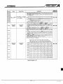
1
REVISIONS
The manual number is given on the bottom left of the back cover.
Print Date
Aug., 1992
.
*Manual Number
IB (NA) 66395-A
Revision
First edition
INTRODUCTION
Thank you for choosing the Mitsubishi MELSEC-A Series of General Purpose Programmable Controllers. Please read this manual carefully so that the equipment is used to its optimum. A oopy of this
manual should be forwarded to the end User.
1
*
,f
i
CONTENTS
.
1 GENERAL DESCRIPTION
1 .1
1.2
.......................................................................................................................
1
Features ..........................................................................................................................................
Use with Related Manuals ...........................................................................................................
.
........................................
3. CPU MODULE PERFORMANCE SPECIFICATIONS ...........................................................................
2 COMPATIBLE PERIPHERAL DEVICES AND SOFTWARE PACKAGES
.
4 USER MEMORY WHEN EXECUTING AN SFC PROGRAM
4.1
4.2
4.3
4.4
.
5.1
5.2
5.3
5.4
5.5
5.6
-
..................................................................................................
.
.
.
4
6
7
10
11-13
.......................................................
14. 15
ErrorCodes ..................................................................................................................................
Error LED Indicator Priority Setting ..........................................................................................
7 SFC PROGRAM PROCESSING TIME
7.1
7.2
3
To Execute an SFC Program by Continuation Restart.......................................................... 1 1
Instructions and Devices Usable as Operating Outputs and Transition Conditions ......... 1 1
Microcomputer Program Area of an AnACPU-F ..................................................................... 12
Precautions
when
Reading/Writing
Program
a Using
Computer
a
Link
.............................. 12
Data Stored to the Status Latch Step Number Storage Register (M9055).........................
12
Single Start of an Inactive Block ............................................................................................... 13
6 ERROR CODES WHEN EXECUTING AN SFC PROGRAM
6.1
6.2
2
4-10
Memory Area Allocations for Memory Cassette Users ............................................................
SFC Program Work Area and Step Trace Data Storage Area ................................................
How to Calculate the Area Capacity Used as an SFC Program Work Area .........................
Functions Using an Extension File Register and Area Occupation Timing ........................
5 PROGRAMMING PRECAUTIONS
.- .
.........................................................
1
1
...........................................................................................
16. 17
How to Calculate the Time to Process an SFC Program ......................................................
SFC System Processing Time ...................................................................................................
I
-~
.................
14
15
16
17
..
1. GENERAL DESCRIPTION
1.
MELSEC-A
GENERAL DESCRIPTION
This manual explains theCPU performance specifications, necessary peripheraldevices,andprogrammingprecautions
to takewhenoperatingan
A2ACPU-F, A2ACPU-SI-F, or A3ACPU-F PC (all hereafter called an AnACPU-F) using SFC language.
With an AnACPU-F, SFC processing time is considerably faster than with an
AnNCPU-F (AlSCPU, AOJ2HCPU, and A2CCPU are included).
The AnACPU has been designed to increase the ladder processing speed.
However, theSFC processing timeis longer than the processing
time required
for a ladder processing only.
1.1
Features
(1) The SFC system processing time has been shortened
When operating an SFC program, system p~ocebting time is
necessary
as an overhead. However, this time was reduced. Therefore, as compared with an AnACPU-F, the total scan time has been reduced.
for aninactiveblock has beenadded
(2)Ablocksinglestartfunctions
A function that singly starts an inactive block by using either a sequence
program or a peripheral device has been added. This makes both partial
testing of equipment and debugging of SFC programs easier.
1.2
Use withRelatedManuals
Thismanualgivestheprecautions
to take andthespecifications
of the
MELSAP-II function(SFC) which is necessaryto operate an AnACPU-Fusing
SFC language.
When consulting the relatedmanuals given below, read the indicated sections
as if they were contents of this manual.
Related manuals:
(1) MELSAP-II Programming Manual (IB(NA)66361)
0 Applicable CPU (see Section 2.1)
0 Configuration of the user memory area (see Section 2.2)
0 List of devices (see Section 3.2)
SFC program processing time (see Section 3.3)
Instructions used for operation output/transition conditions
(see Sections 4.3 and 4.6)
0 List of error codes (see Section 8)
(2) SWOIX-SAP2E (MELSAP-II) Operating Manual (IB(NA)66313)
Applicable CPU (see Section 2.1)
0 Inactive block single start (newly-added function)
(3) SWOIX-GPPAE GPP Function Operating Manual (IB(NA)66314)
0 Parameter memory capacity setting (see Section 7.2)
Precautions to take when setting the microcomputer program capacity for an AnACPU (newly-added function)
(4) A2A(SI)/A3ACPU User’s Manual (Control Functions) (IB(NA)66256)
CPU module performance specifications (see Section 3.1)
User memory allocation (see Section 5.1.2)
Changing LED display priorities (see Section 3.16)
( 5 ) TheUser’sManual
of eachspecialmodulethatcanread/writeasequence program
Microcomputer program read/write suitability (seethe sectionin each
particular manual that explains the commands)
-1-
,
-
n
4
:3
2. COMPATIBLE PERIPHERAL DEVICES
AND SOFTWARS,PACKAGES
- MElsKGA
2.
COMPATIBLE PERIPHERALDEVICESAND SOFlWARE PACKAGES
Tabie 2.1 showstheperipheraldevicesthat
can and cannot be used for
creating and debugging SFC programs when operating an AnACPU-F using
the SFC language during monitoring, as well as the software packages for
the GPP and SFC functions.
Table 2.1 Comblnations of Compatible Perlpheral Devices and Software Packages
Poripheral Devices
'1 A7PHPE
PC/AT or compatible
GPP Function Sottwaro Packages
'1 SWORX-GPPAE
' 2 SWOIX-GPPAE
POINTS
YELSAP-I! (SFQ Function
sottwm
'1 SWORX-SAPPE
SWOIX-SAP2E, Version B or earlier
SWOIX-SAPPE. Version C or later
Combinable
OK
NG
OK
I
(1) *I
: Available as of July, 1992.
'2: There areno restrictions on which SWOIX-GPPAE GPP function
software package can be combined with the MELSAP-II(SFC)
function software package SWOIX-SAP2E.
(2) TheSW4GP-GPPAGPPfunctionsoftwarepackageforan
A6GPP/MPHP. is version E or later. If the version is E or later,
there is an additional function about microcomputer program capacity setting in the memory capacity setting option of parameter
setting for an AnA-F.
SFC programs cannot be created and displayed. Memorycontents
canbeconfirmedandchanged.Microcomputerprograms(SFC
programs) can be read/written from/to the CPU and a floppy disk.
-2-
3. CPU MODULE PERFORMANCE SPECIFICATIONS
This seetion indicates how the performance specifications of an AnACPU-F
differ from those of an-AnACPU.
Any specifications not given
in this section are the same for both an AnACPUF and an AnACPU.
-The A2A(Sl)CA3,ACPUUser's Manual (Control Function) gives details.
Items
Available memory
ABAIAmCPU-S 1-F
A3NMCA-0 *1
ABACPU-F
A3NMCA-0 '1
A3NMCA-56
Sequence program
A3NMCA-56
A3AMCA-96
Sequence program
microcomputer program 2
= max. 14 Ksteps (28 Kbytes)
microcomputer program 2
= max. 30 Ksteps (60 Kbytes)
1
cassette
+
Main program
capacity
Microcomputer program
= max. 13 Ksteps (26 Kbytes)
can be set.
Sub-program
capacity
No function.
1
+
Microcomputer program
= max. 29 Ksteps (58 Kbytes)
can be set.
Sequence program
= max. 30 Ksteps can be set.
(Microcomputer programs cannot be
set.)
*1: Since work areasfor an SFC program cannot be allocatedin an A3MCA-0
or A3NMCA-0, an A3MCA-0 and A3NMCA-0 cannot be utilized.
*2: Since the microcomputer program area can only be used for storingSFC
programs, the microcomputer program area cannot be used for storing
microcomputer programs created bya user.
I n addition,,themlcmcomputerprogramareacannotbeusedasan
additional area for ufility software packagesfor the MELSEC-A series.
r '
w
-3-
4.
USER MEMORY WHEN EXECUTING AN SFC PROGRAM
This section explains the relationship between user memory areas in SFC
an
program work area andmemory cassettes needed to execute SFC programs.
4.1
Memory Area Allocations for Memory Cassette Users
Table 4.1 showsthe memory area allocations for memory cassette users
when doing parameter setting.
Table 4.1 Memory Area Allocatlons for Memory Cassette Users
ROM me6ory
area
Unusable
Parameter area
T/C set value area
(main program use)
sequence
puter area
T/C set value area
(sub-program use)
+5
RAM mc3n
area
Sub-sequence program area
System area for sub-sequence execution
Extension comment area
1 Block No. 8
Extension
file register
1 Block No. 1
I
File register area
Comment area
Extension
I Block No. 0
... 3 Kbytes (indespensible)
... 1 Kbytes (indispensable)
... Set parameters in the range of
1 to 30 Ksteps
(2 to 60 Kbytes).
... Set parameters in the range of 2 to 58 Kbytes
(However, it can be set within 60 Kbytes with a
sequence area.)
... 1 Kbyte (When a sub-program is set)
... Set parameters in the range of 0 to 30 Ksteps
(0 to 60 Kbytes).
(Settings can only be done with an A3A-F.)
... 5 Kbytes (When a sub-program is set)
... When a capacity is set using a parameter
1
... One block = 16 Kbytes *2/+3
max. 8 blocks
Set parameters in the range of 0 to 16 Kbytes.
... Set parameters in the range of 0 and 2 to 64
Kbytes.
1
... 1 block = 16 Kbytes
-4-
With an A2A(S1) : 0 = 2 8
With an A3A
:0 = 4 8
4. USER MEMORY WHEN EXECUTING AN SFC PROGRAM
Kbyt9s)wkensetting an
No. 10 of
extension comment. Extension comments are stored after block
,the exteffsioriYite register.
If an extenbion comment isstored
in block No. 10, area 4) is the available
area for calculating the number of blocks of extension file registers of
block Nos. 1 408.
If the block area after No. 10 is smaller than the set extension comment
CPU write
capacity, the memory areawillbeinsufficient.Therefore,
operations cannot be done.
*2: Calculate the available number of blocks of anextension file register
(block Nos. I.
to 8 )
1) - 2) - 3) - (4)) - 5) K bytes= nl
0 During RAM operation
16
1) - 3) - (4)) - 5 ) Kbytes= n2
0 During ROM operation
16
The integer value of n l and n2 is the available number of blocks in block
numbers 1 to 8 .
*3: Designate an extension file register b,bck number
to the data storage
area
trace and
numbers Qf abampling trace and a status latch when a sampling
status Iatdh are being executed online.
'4: This area ?An be stored to the ROM.
When this area id"stored to the
ROM, areas 3) and 4) are condensed. And
then, the site of an 'available area for calculating the numberof available
blocks of extension file registers of block numbers 1 to 8 increases.
*5:The following table gives the capacitiesof each-memory cassette model.
*1: If the.'&tension coinmemcapacify Y (f)-Zj-3)-5)
i
I
Marllr9ry Cassette
Node1 Names
Memory Carsetts
Capacities
Capacities
in Table 4.1 (1)
-
AB(N)MCA-O
A3(N)MCA-2
A3( N)MCA-4
16 Kbytes
16 Kbytes
32 Kbytes
32 Kbytes
64 Kbytes
A3MCA.12
64 Kbyles
96 Kbytes
A3NMCA-16
A3MCA- 18
128 Kbytes
144 Kbytes
96 Kbytes
A3NMCA-24
192 Kbytes
144 Kbytes
144 Kbytes
A3NMCA-40
320 Kbytes
144 Kbytes
A3N MCA-56
448 Kbytes
144 Kbytes
A3NMCA-96
768 Kbytes
144 Kbytes
A3( N)MCA-8
1(only for an A3A(-F))
-5-
96 Kbytes
I
4. USER MEMORY WHEN EXECUTMG AN SFC PRO6RAM
4.2
#-.
SFC Program Work Area and Step Trace Data Storage Area
(1) SFC program work area
When executing an SFC program, the system uses 4 Kbytes of the user
memory area of a memory cassette as an SFC program work area. In
addition, the system uses amax. 12 Kbytes asthe step trace datastorage
area.
If the user memory area of a memory cassette does not have an available
capacity of 4 Kbytes or more, SFC programs cannot be executed.
Whenexecutingasteptrace,2
to 12 Kbytes of availablearea are
necessary in addition to the 4 Kbytes for the work area.
(2) Howtocalculatetheavailablecapacity
of a memory cassette’suser
memory area
Theavailablecapacity
is calculated by subtracting the parameter-set
memory capacity from the total area that can be parameter-set.
Max. 144 Kbytes (Area indicated in Table 4.1 (1))
Samplecalculation: The following shows asamplecalculation
of an
availablecapacitywhenthefollowingconditions
have been satisfied.
Memory cassette .....A3NMCA-24
Main program
(microcomputer program included).....10 Ksteps
File register.....4 Kpoints
Comment .....40 Kbytes
Memory space capacity =
144K-(3K+l K+20K+8K+40K)=72Kbytes
1)
2)
3)
4)
5)
6)
1): Capacity of an A3NMCA-24 that can be parameter-set
(Area indicated in Table 4.1(1))
2): Parameter storage area
3): T/C set value area
4): Main program (1 step 2 bytes = 10 Ksteps x 2)
5 ) : File register (1 point 2 bytes = 4 Kpoints x 2)
6): Comment capacity
The memory space capacity is calculated as 72 Kbytes.
-6-
4. USER MEMORY WHEN EXECUTING AN SFC PROGRAM
4.3
-M€LSEGA
How to Calculate the Area Capacky U W as m SFC Pmgram Wotlr Area
A;'
n
L
This section showshow to calculate thearea capacity of the memory cassette
that is usedas an SFC programworkarea andwhether or not an SFC program
can be executed.
When an SFC progPam cannot be executed in the following explanation, it is
necessary to changeeither(a)the
memory cassette, or (b)thememory
capacity parameter setting.
The memory capacity set with a parameter in the following explanation is the
sum of the memorycapaqity when a userset or changed the memory capacity
set with parameters.
The default value is 16 Kbytes.
(1) If the memory cassette is one of the following:
A3(N)MCA-2
A3(N)MCA-4
A3(N)MCA-8
A3MCA-12
(Area capacity of Table 4.1 (1 ))
- (Memory capacity set with a parameter) = A
A : 16
Kbytes or more
canbe executed, and amax. 12 Kbytes step trace
capacity can beoccupied.
Since extension file register No. 1 is utilized as an SFC program
work area, this cannot be utilize'd as an area for user data storage.
: More than 4 Kbytes less than 15 Kbytes
......an SFC program can be executed.
Step trace capacityS A - 4 Kbytes.
: 4 Kbytes or less
......an SFC program cannot be executed.,
......an SFC program
-7-
1
c1
)r
4. USER MEMORY W H N EXECUTING AN SFC PROGRAM
MLSEGA
(2) If the memory cassette is the following:
A3NMCA-16
(Area capacity of Table 4.1 (1))
- (Memory capacity set with a parameter) = A
When an extension comment capacity is set, and A is minus
(Area capacity of Table 4.1 (1)) (Memory capacity set with a parameter - extension comment capacity) =
A : 16 Kbytes
......an SFC
or more
program can be executed,
and a max. 12 Kbytes step trace
capacity can beoccupied.
Since extension file register No. 1 is utilized as an SFC program
work area, this cannot beutilized as an area for user datastorage.
: 15 Kbytes or less
......an SFC program can beexecuted, and a max. 12 Kbytes step trace
capacity can be occupied.
However, the work area is movedto extension file register No.10.
Since extension file register No. 10 is utilized as an SFC program
work area, this cannot be utilized as an area for userdata storage.
B : 16 Kbytesor more
......an SFC program can be executed, and max.
a 12 Kbytes step trace
capacity can beoccupied.
Since extension file register No. 1 is utilized as a SFC program
work area, this cannot be utilized as an area for userdata storage.
: More than 4 Kbytes and less than 15 Kbytes
......an SFC program can be executed.
Step trace capacity I B - 4 Kbytes.
: 4 Kbytes or less
......an SFC program cannot be executed.
(3) If the memory cassette type is the following:
A3NMCA-18
(Area capacity of Table 4.1 (1))
- (Memory capacity set with a parameter) = A
A : 32 Kbytes or less
......an SFC program
-..
can be executed and max.
a
12 Kbytes step trace
capacity can be occupied.
Since extension file register No. 2 is utilized as an SFC program
work area, this cannot be utilized as an area for userdata storage.
: More than 4 Kbytes less than 15 Kbytes
......an SFC program can be executed.
Step trace capacity I A - 4 Kbytes.
: More than 16 Kbytes and less than 31 Kbytes
......an SFC program cannot be executed.
However, an SFC program can be executed by parameter setting
of a dummy capacity and setting the capacity of "A" at 15 Kbytes
or less.
: 4 Kbytes or less
......an SFC program cannot be executed.
-8-
4. USER MEMORY WHEN EXECUTING AN SFC PROGRAM
t
(4) If the memory cassette is one of the following:
A3NMCA-24
0 A3NMCA-40
A3NMCA-56
A3NMCA-96
(Area capacity of Table 4.1(1))
- (Memory capacity set with a parameter) =A
When an extension comment capacity is set, and A is minus
(Area capacity of Table 4.1 (1 )) (Memory capacity set with a parameter - extension comment capacity)
4
=&
A : 32 Kbytes or more
., , ,..an SFC program
be
be
canbe executed, and a max.12 Kbytes step trace
capacity can be occupied.
Since extension file register No. 2 is utilized as an SFC program
work area, this cannot be utilizedas an area for user data storage.
: 15 Kbytes or less
......an SFC program can be executed, and a max. 12 Kbytes step trace
can
capacity
occupied.
However, the work area is moved to extension file register No. 10.
Since extension file register No. 10 is utilized as an SFC program
work area, this cannot beutilized as an area for user datastorage.
-6 : 32 Kbytes or lees
......an SFC program can be executed, and max.
a 12 Kbytes step trace
can
capacity
occupied.
Since extension file register No. 2 is utilized as an SFC program
work area, this cannot be utilizedas an area for user data storage.
: More than 4 Kbytes and less than 15 Kbytes
......an SFC program can be executed.
Step trace capacity s B - 4 Kbytes.
: More than 16 Kbytes and less than 31 Kbytes
......an SFC program cannot be executed.
However, an SFC program can be executed by parameter setting
of a dummy capacity and setting the capacity of "A" at 15 Kbytes
or less.
: 4 Kbytes or less
......an SFC program cannot be executed.
-9-
q
U
.._,
l
a
4. USER MEMORY WHEN EXECUTINGAN SFC PROGRAM
4.4
Functions Using an Extension File Register
MECSEGA
and Area Occupatlon Tlmlng
Table 4.3 shows the functions using an extension file register, area occupation timing, and area occupation priorities.
Table 4.3 Functions Using an Extension File Register and Area Occupation Tlmlng
Functions Uaing an Extension
File Rogkter
Area Occupation Timing
Area Occupation
Priority
Extension comment
When a parameter with which an extension comment capacity was set is written to a CPU
1
SFC work area
When a parameter with which a microcomputer program capacity was set is written to a CPU
2
Ontine sampling trace
Online status latch
When tracenatch data storage register No. is set and i s written to a CPU
3
Extengion file register access
instruction
Access by a computer link
When an instruction is executed or when a computer link is
Presence or absence of the corresponding block numbers
and access validity are checked at this time
4
*I
:If the memory capacity of a parameter is changed after executing an S F C
program, block No. 10 of an SFC program work area sometimes changes.
Sections 4.1 and 4.2 give details about confirming the block number that
is used as a work area.
'2:If an SFC program is designated to the continuation start and a program
is started when a parameter is first written to a CPU or when the memory
capacity of a parameter is changed,
SFC PARA.ERROR (error code 80
and detailed error code 804) occur. And then, an SFC program is started
from the initial step of block 0.
- 10-
5.
PROGRAMMING PRECAUTIONS
This section givss the precautions to take when programming to execute an
SFC program on an AnA-F.
5.1
To Execute drvSf% Program by Cdntfnuatlon Restart
(1) To execute an SFC program by contunuation restart on an AnA-F, special
relay M9102 must be turned ON (contunuation restart) all the time an
SFC program is being executed.
If M9102 is .turned ON when an SFC program is restarted, after it
is
executed with M9t02 being turned OFF, the SFC PARA. ERROR (error
code 80, detail error code 804) message is displayed. Then, an SFC
program is started by initialstart (start with the initial step i n block 0).
(2) When an SFC program is executed, the SFC processing time of the CPU
varies according to the ON/OFF status changes of M9102.
The list of processing times in Section 7.2 gives details.
5.2
instructions and Devices Usable as Operating Outputs and Transition Conditions
(1) Instructions usable as operating outputs
and
(a) Common instructions except for the following are usable:
CJ, SCJ, JMP, FEND, RET, IRET, MC, MCR,CHG, CHK, and labels
Pn
In
(b) Dedicated instructions except for the following are usable:
BREAK, CHK, and CHKEND
(2) Instructions usable as transition conditions
0 Contact instructions:
LD, LDI, AND, ANI, OR, OR1
Branch end instructions:
ANB, ORB
0 Comparison operation instructions:
LD(D)=
, LD(D)>
, LD(D)>=
D)<
LD(
, LD(D)<=
,
AND(D)=
, AND(D)>
, AND(D)>=
AND( D)c
, AND(D)<=
,
OR(D)=
,OW)>
, OR(D)>=
OR(D)c
, OR(D)<=
, LD(D)o
, AND(D)<>
, OR(D)o
(3) Devices usable with an SFC program
Extension devices (M2048 to 8191, Dl024 to 6143, etc.) of an AnACPU
can be utilized in the ladder circuits of operating outputs and transition
conditions, and for SFC data registers when used with an SFC program.
- 11 -
m
b''
+
'd
5. PROGRAMMING PRECAUTIONS
-
5.3
“€CIA
Microcomputer Program Area of an AnACPU-F
Using a microcomputer program with an AnACPU-F
The microcomputer program area of an AnACPU-F can be utilized for
storing an SFC program.
This area cannotbe utilizedfor storing a user’s microcomputer programs
or as an additional areafor a utility software package for the MELSEC-A
series.
Precautions when writing a parameter
to a CPU when the parameter has
been set with a microcomputer program capacity
If an attempt is made to write a parameter with which a microcomputer
program capacity has been set to an AnACPU which does not have the
-F code, a parameter error occurs which disables the CPU.
Do not set a microcomputer program capacity
with a parameter on a
peripheral deviceexceptwhenan
SFC programisexecutedwithan
AnACPU-F.
5.4
Precautions when Readlng/Writing a Program Using a Computer Link
If a microcomputer program (SFC program) of an AnACPU-F is read/written
by using a computer link, the following module is unable to execute such a
program:
AD51 H intelligent communications module
When a module which is capable of reading/writing a program is utilized, a
microcomputerprogramcanberead/writtenbyusingacommand
to
read/write a microcomputer program.
56
Data Stored to the Status Latch Step Number Storage Register (M9055)
Special register D9055 which is utilized to store a status latch execution step
number when status latch is executed is utilized
to store the SFC process
execution block and step numbers when an SFC program is executed.
0
When status latch is executed:
A status latch execution step number is stored.
If an SFC program is executed after the execution of status latch, stored
data will be overwritten. Therefore, data stored by the execution
of status
latch must be saved toany other register to avoid overwriting.
When an SFC program is executed:
The SFC process execution block and step numbers are stored.
Execution block number
(stored inBIN)
Higher 8 bits
Execution step number
(stored in BIN)
I I
- 12-
Lower 8 bits
5. PROGRAMMING
PRECAUTIONS
Start
5.6 Slngle
lnactlveof an
. 9'.
Block
i
k"w&+xa
3
Starting a sub-block other than block 0 requires a sub-block start request
issued by any other blodc in an SFC program.
When an SFC program is executed in an AnACPU-F, any designated block
can be started by turning ON the block activating bit of an inactive block by
using a program or the test $unction,
etc. of a peripheral device.
(1) How to execute single start of a block
Any of the fotkwing-rnethodscan beutilized for single startof an inactive
block:
Create a program which twns ON the block activating bitof a block
when a condition Is established in a sequence program.
Forcibly turn ON the block activating bitof a block by using the test
function of a peripheral device.
Forciblyturn ON theblockactivating
computer link.
bit of ablockbyusinga
(2) Precautions when executing single start of a block
The following precautions must be taken when single start is executed to
a designated block:
Each block activating bit needs to be set as a data register in each
block.
If the block activating bit
of an actlve blockis turnedON by the single
start function, the start request is ignored and that block continues
execution of an SFC program.
If a sub-block start is executed by an SFC program to a block which
has been activated by the single start function, theEXE.ERROR
SFC
error occurs.
To execute sub-block start by an SFC program, the block activating
bit of a corresponding block needs to &e insluded as an interlock in
the transition conditions for executing the sub-block start.
Since the block activating bit is turned OFF by the system when the
end of the corresponding block has been reached, the user does not
need to turn OFF (RST) the bit.
If a block activating bit which
is ON is forcibly turned OFF by a
sequence program or peripheral device, the end of the corresponding block will not be reached and the block remains active.
In this case, the block activating
bit which is includedas an interlock
for executing a sub-block start by an SFC program is turned OFF,
disabling the interlock function. An SFC EXE.ERROR error occurs
since a block start requesthasbeenmade
to an already-started
block.
- 13-
6. ERROR CODES WHEN EXECUTING AN SPC P R O G W
6.
6.1
U6LSEC-A
ERROR CODES WHEN EXECUTING AN SFC PROGRAM
Error Codes
'1
Error
Code.
Table 6.1 lists themessages and codesof the errors thatcan be caused when
executing an SFC program, and the corresponding CPU statuses.
Table 6.1 Error Codes
Detail Erro'i
Codes
Laddors
SFC
Cannot start the SFC program since the memory cassette is A3(N)MCA-O.
801
SFC PARA.
ERROR
802
80
1
I
CPU statuses
A large enough work area for the SFC program cannot
be assigned since the user's memory has free space of
4 Kbytes or less.
stop
Continue
803
804
The SFC program area in the memory cassette is memory-protected.
Initial start
805
The memory capacity parameter was changed when continuation restart was designated (M9102:ON).
The CPU was reset when continuation restart was designated (M9102:ON).
The SFC program contains an instruction that cannot be
decoded.
SFC CODE
ERROR
81
stop
Stop
SFC STEP
OVER
82
stop
Stop
The number of simultaneous active steps of the SFC program exceeded the maximum ( 1 024).
SFC EXE.
ERROR
83
stop
Stop
A request was made to start an active block that was already started.
'4
Continue
/Stop
Continue
/Stop
SFC OPE.
ERROR
84
-
831
840
'3
After changing the memory capacity parameter, the SFC
program capacity became greater than the microcomputer program capacity.
'4 An arithmetic operation error occurred. The device
range was exceeded when performing an operating output in the SFC program or computing transition conditions using the ladder diagram.
*1 :Data registerD9008 stores an error code.
'2:Data register D9091 stores a detail error code.
*3:0 indicates the lowest digitof the detail error code (OPERATION
ERROR)
which occurred when executing the program.
Example:
When data or a constant in a designated device exceeded the
allowable range.
Executed Programs
Error Codes
Detail Error Codes
When executing a main program
50
503
When executing an SFC program
84
843
'4: Determined by the error operation mode setting.
The default is "continue".
- 14-
6. ERROR CODES WHEN EXECUTING AN SFC PROGRAM
6.2
r5
Error LED lndlcator Prlorlfy -5ettfrg
._
This section describes (a) the causes
and (b) the error indication priority.
of the errors that IightMlash the LED,
(1) Error causes that unconditionaUy light/flash the LED
When causing an error that stops the CPU.
(2) Error causes (a).whose priority to lighvflash the LED can bechanged, or
(b) that canbe set to not to IlghVflash the LED
The following error causes can be
set in special registers 09038 and
D9039 to change their priority or to disable light/flash of the LED.
I Cause
I
NO.
II ’ II
1
Error Causes
InpuVOutput verification
error, fuse blown
%ecial-function module
errof, )ink parameter error,
3
CHK instruction error
4
Annunciator (F) ON
5
LED instruction
6
7
,
Battery error
Clock data
- 15-
I
A3A-F
APA-F
I
I
Outputs the c o r m
message to the
LED display module when an error
occurs.
Error LED lit.
I
l
Error LED flashes.
-
Error LED lit.
-
n
w
7. SFC PROGRAM PROCESSING TIME
7.
MELSEGA
SFCPROGRAMPROCESSINGTIME
This section describes the time required to process a sequence program and
an SFC program.
7.1
How to Calculate the Time to Process an SFC Program
This section explains(a) how to calculate the time required
to execute anSFC
program, and (b) the scan time.
time to processa
Scan time = sequence
program
+
timetoprocessan
SFC program
+
END processing
time
1)
2)
3)
1) Total processing timeof instructions used in the main (sub) sequence
program.
2) Total of the time of instructions processed for operating output and
transition conditions and of system processing.
SFC program
processing time
Time of instructions
processed for operating
outputandtransitionconditions
(a) Time of instructions processed for operating output and transition
conditions
Time of instructions
processed for operating
output and transition conditions
=!
1
Time of instructions
processed for
operating output
+
Time of instructions
processed for
transition conditions
Operating output instructions processing time
Total processing time of instructions used for operating output of all executable (active) steps.
If the transition conditions are satisfied, "total processing time
x 2" will be applied.
0 Transition condition instructions processing time
Total processing time of the instructions used for transition
conditions included in all executable (active) steps.
(b) System processing time
Section 7.2 gives details about the system processing time and a
calculation example.
3) END processing time (self-diagnosis, etc.)
- 16-
7.2
SFC System Processlng Time
This section explains the system processing time (when executing an SFC
program) in comparison with the AnNCPU-F.
Table 7.1 SFC System Processlng Tlme
In the case of initial start
h,
SFC END processing
‘
k
d
SFC system processing time calculation example:
Designate continuation restart (M9102: ON)
Number of active blocks: 30
(Active blocks used for anSFC program)
Number of inactive blocks: 70
(inactive blocks used for an SFC program)
Number of available blocks: 50
(Blocks set bythe parameters that are not used foran SFC program)
Number of active steps: 60
(Active steps in active blocks)
0 Transition condition included in active steps: 60
Transition condition satisfying steps: 10
(Active steps that satisfy transition conditions)
SFC system processing time = 195 + (57x 30) + (14 x 70) + (4 x 50)
+ (49.5 x 60)+ (29.5 x 60)+ (17 x 10)
= 7795 ps = 8 msec
As indicated above, the SFC system processing time is8 msec.
Under the same conditions, however, it is approx.
11 msec in the
case of an A2ACPU-F; approx.44 msec in the case
of an AnNCPU-F.
The scan time consistsof the SFC system processing time, the time
required to process the transition conditions
included in the SFC
active steps, and the CPU END processing time.
i
- 17-
IMPORTANTI
C
(1) Design the configuration of a system to provide an external protective or safety inter
locking circuit for the PCs.
(2) The components on the printed circuit boards will be damaged by static electricity,
so avoid handling them directly. If it is necessary to handle them take the following
precautions.
(a) Ground human body and work bench.
I
I
(b) Do not touch the conductive areas
of the printed circuit board and
parts with and non-grounded tools etc.
its electrical
I
Under no circumstances will Mitsubishi Electric be liable or responsible forany consequential
damage that may arise as a result of the installation or use of this equipment.
1
All examples and diagrams shown in this manual are intended only as an aid to understanding
the text, not to guarantee operation. Mitsubishi Electric will accept no responsibility for actual
use of the product based on these illustrative examples.
Owing to the very great variety in possible applications
of this equipment, you must satisfy
yourself as to its suitability for your specific application.
I
I
A MlTSUBlSHl
ELECTRIC
CORPORATION
When exported from Japan, this manual does not require application to the
Ministry of International Trade and Industry for sewice transaction permission
IB (NA) 66395-A
(9208)
MEE
Printed
Japan
Specifications
in
subject
change
towithout
notice
‘I
‘I,
Jumber
Stored Data
Name
Explanation
When VO module
data
is different
entered
those
from
at power-on
have
16 points) are entered
been detected, the UO module numbers (in units of
in bit (Preset
pattern.
I/O
parameter
has
numbers
module
when
setting
been
'D9116
'D9117
performed:)
lnar 4 0
110
''D9123
D9124
~9116
Bit
Pattern
in
modules
of 16 pointsofverify
error modules
module
1 5 1 4 1 3 1 2 1 1 1 0 9
8
7
6
5
4
3
2
1
w117
W123
h n d k a t e a VO unit verify error.
(Ifnormalstatusisrestored,clearisnotperformed.Therefore,
required to performclearby
user program.)
I
it is
09124. (ForABNCPU, it can
executed, 1 is subtracted from the contents of
detectionbeperformedbyuseof
INDICATOR RESET switchonfront
face of CPU
Annunciator
Annuhciator
detection
I
0
I
I
D9125
D9126
D9127
When one ofFO t o 255 is turned on by
( O U T j or
which has turned on, i s entered into D9125 to D9132 il
code.
F number, which has been turned
off by
is erased from D9125
to D9132, and the contents of data registers succeeding the data register,
where theerased F number was stored,are shifted to the preceding data
registers.
By executing1 instruction, the contents of 09125
to D9132 are
shifted upward by one. (For A3NCPU, it can be performed by use oi
INDICATOR RKSET switch on frontof CPU unit.)
When there are 8 annunciator detections, the 9th one is not stored into
D9125 to 9132 evenifdetected.
IRSTl,
SETSETSETRETSETSETSETSETSETSETSET
F50F25F1QF25
F15 F70F65F38
FllOF151F210 LEDR
.
n4nn-qn-n-n-
D9128
Annunciator
detection
number
Annunciator
detection
number
~
D9009
D9124
D9129
W125
09126
D9127
D9130
D9128
D9129
D9131
D9130
D9131
D9132
D9132
I
I
I
Special Register List
APP-13
IB IhAI 66161-A
(1) All specialregister-data is cleared by anyofthe
data is
power-off, latch clear and reset operations. The
retained when the RUNISTOP switch is sett o STOP.
(2) For the above speoial registers with numbers marked
'1, the contents of register are not cleared if normal
status is restored. Therefore,
t o clear the contents, use
the following method:
Clear execution
1) Method
by
F
L
[
R
S
T D9005d
user program.
Insert the circuit shown at right into the program
and turn on the clear execution command contact
t o clear the contents of register.
2) Method by peripheral equipment.
Set the register t o ' 0 " by changing the present
value by the test function of peripheral equipment
or set t o "0" by forced reset. For the operation
procedure, refer to the manual of each peripheral
equipment.
3) By moving the RESET key switch at the CPU front
t o t h eRESET position, the special register is set
to
'0".
(3) Data is written to the special registers marked *2 b y
the sequence program.
I!
i
#
APP-14
4
IB INA) €6161-A
d
i
APPENDIX 4 Dimensions
4.1 CPU module
11
, 4.2 (0.17)
, , 3(0.12)
I 1-
Printedcircuit
board
1.2 (0.17)
-
121(4.76)
79.5 (3.13)
-1
J
Unit: mm (inch)
APP-15
IB INAl €6161-A
4.2 Power supply modules
(1) Type A61P,A62P,A63P,A65P
1
power supply moduies
A65P
0 POMR
@
FUSE
c
4
INPUT
.C1001200"
3
3
.
SHORT AC,OO"
SHORT l C 2 D G V
LO
FG
4.2 10.17)
i
OUTPUT
\
55 (2.17)
(forterminalscrew)
Unit: mm (inch)
APP-16
.
~
.
IS (NAI 66161-A
t
6
L.
(2) Type A66P powersupply
1
4.2(0.17)
module
,+
M3 (0.12) X 0.5 (0.02)X 6 (0.24)
(Terminal
screw)
Printed circuit board
...
J
-
II
-.
6(0.24)
106(4.17)
121 (4.76)
Unit: m m (inch)
4.3 Basic base units
(1) Type A326 base unit
10-M4
screws
(Metric
screws)
dia.
installation
holes
Hand
module
installation)\
(for
hold
4-6mm (0.24 inches)
/(M5 mounting screw)
i
i
227 (8.94)
(1.14)
i
Unit:mm(inch)
(2)Type A35B base unit
Hand hold
7
4-6mm (0.24 inches)
dia. installation holes
'(M5 mounting screw)
16-M4 screws (Metric screws)
(for module installation)
\
\
\
E
0
Base cover
/
t
1
362 (14.25)
382 ( 15.04)
1291
(1.14)
Unit:mm(inch)
APP- 18
IB iNAi 66161-A
?
0
I
APPENDICES
(3)Type A38B base unit
22-M4 screws Metric screws
4-6mm(0.24inches)
dia. installation holes
Unit: mrn (inch)
APP- 19
IB (NAI 66161-A
4.4 Extensionbaseunits
(1) Type A65B base unit
12-4Mscrews(Metricscrews)
(for
module
installation)\
(M5
mounting
screw)
4-6mm(0.24inches)
dia.installationholes
Base cover
Hand hold
7
(2) Type A68B base unit
18-4Mscrews(Metricscrews)
(for module installation)\
Base cover
d ddddddddB
Hand hold
7
j
4-6mm(0.24inches)
dia.installationholes
/(M5 mounting
screw)
0
0
Lci
(v
I_
1291
(1.14)
3
'
APP-20
Unit: mm (inch)
IB INA) 66161-A
#
1.
tc
d
10-M4 screws (Metric screws)
/m-rJnting screw)
dia. installation holes
IO1
F
I
c
L
129
277 (10.91)
297 (1 1.70)
-
(1.14)
Unit:mrn(inch)
(4) Type A58B base unit
4-6mm (0.24 inches)
16-M4 screws (Metric
screws)
dia.
installation
holes
/(M5 mounting
screw)
(for
module
installation)\
4
Base cover
4
+
+
+
+
4
\
+ /
/
t
-
Hand hold
I
I
01
391 (15.39)
411 (16.18)
- =I
1
(1.14)
0
Unit:mrn(inch)
APP-21
IB (NA) 66161-A
.
c
4 PULL
L
i
I
I
Unit: rnrn (inch)
APP-22
r
4
IB iNAl 66161-A
4