1
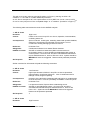
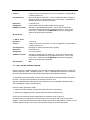
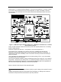
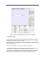
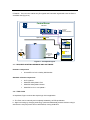
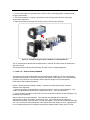
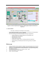
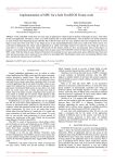
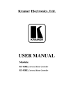
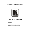
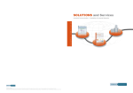
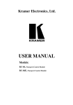
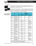
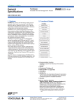
SIEMENS INDUSTRY INC. Tank protection example using Simatic Luis M.F. Garcia G - CFSE 2/11/2013 Introduction Objective of this essay For protection of tanks holding volatile fluids, the industry best practice has traditionally been documented various application specific prescriptive standards and guidelines, such as the API 2350 guide from USA. But recent events have caused the industry to rethink overall protection requirements and to also embrace a more performance oriented functional safety approach, alongside a review of existing prescriptive standards. For the process industry, the standard for designing a Safety Instrumented System (SIS) is IEC 61511. The Safety Life Cycle (SLC) from IEC 61511 has been widely adopted for implementation and operation of safety related systems to help manage risk in the process industry. Many companies now seek to apply the IEC 61511 standard, in addition to other national standards and guidelines. Such approach would help cover all aspects of Tank protection initial specifications right trough the life of the project; detailing not only what has to be done but also how well it has to be done, creating consistency in the approach to safety and helping address the specific risks associated with tank farm facilities. The presented essay narrates an example a methodology that could be used to simplify the development of a Tank Protection System to guard against typical hazards (Overfill, Implosion etc.) to satisfy the requirements of both prescriptive standards and guidelines; and the performance based functional safety standard IEC 61511. This note will NOT discuss typical problems normally associated with these types of applications (Geography, hazardous area classification, occupancy etc.) 1 – PROCESS DESCRIPTION In summary, whilst API is more prescriptive for say “Overfill Protection for Storage Tanks in Petroleum Facilities”; IEC 61511 (Safety Instrumented Systems for the Process Industry Sector) is more performance based. Using both approaches yields the ability to address more complex issues specific to a given facility and also provides a consistent methodology across the safety landscape for other applications on the facility and across the enterprise. In other words; by careful examination of the core issues around tank automation, the restrictions around safety, and emerging technologies, systems can be designed to accommodate both of the standards and still manage to operational and budget constraints. This is the case of a tank that receives Crude Oil from a ship. Once the tank is full, the valves are re-aligned for another tank, out of a group of six to be filled. The tank meets the reception requirements of a small refinery (San Luis Refinery) in the coast line. The total amount of tanks in the farm is 38 with a minimum separation of 15 meters between tanks pools (dikes) Figure 2 shows the P&ID for the application. Following IEC 61511, a LOPA is carried on each of four SIFs which were identified in a previous HAZOP workshop 2 – IMPLICIT LOPA METHODOLOGY Implicit LOPA is a methodology by which application engineering to ILP (Independent Layer of Protection) performance requirements can be estimated ensuring homogeneous criteria is applied corporation wide as all Safety Life Cycle calculations are embedded in the table. >10.000 10.000 - 1.000 1.000 - 100 100 - 10 1 A A A B 10 - 1 B 10 A A B B C C 100 A B B C 1.000 B B C C D 10.000 B C C D D CWA x 50 Frequenciy Cathegories - Years Consequences Consequence reduction Frequency reduction x 100 3 2 1 Consequence Cathegories 1 - No injuries – First aid's 10 – No incapacitated Injuries 100 – Incapacitated w/o fatalities 1.000 - At least one fatality 10.000 – Multiple fatalities Zone Definitions: A. Acceptable design – No changes required B. Consider additional protections C. Require additional protection D. Redesign Figure 1: Example of Safety Performance requirements for a SIF for overfill protection using implicit LOPA methodology. Figure 1 shows in this example how consequences were assigned values by order of magnitude. Note: This is an example and as such, all data is indicative and should not be used in any specific real life application. However, taking a single order of magnitude as RRF1 is a recognized recommended practice. An outer layer, a Fire and Gas System – F&GS (that provides mitigation in the event of spills and fire) reduces consequences. A full fault tree analysis can be performed and the “Weighed Average Consequence - CWA” can be calculated for all possible outcomes2 and all possible frequencies. In this example the ILP reduces from an unmitigated CWA of 5000 to a mitigated CWA of 100. (Position 1 in Figure 1) The Root cause (initial event) frequency is estimated to be once in ten times per year (0.1 per year). This coincides with typical data for performance based standards, and will place the frequency in the last column to the right of the table. On the other hand, there are two Independent Layers of Protection; that will reduce the likehood of the undesirable event: The first one is occupancy. The area is not manned with the exception of maintenance work (usually a couple of days in a year per tank). The other protection is the pit itself or bund around the tank, which is a passive ILP with an accepted performance of one order of magnitude. Both IPLs provide a combined protection of 2 orders of magnitude. (i.e.: x 100) 1 RRF (Risk Reduction Factor) = 1/PFD AVG Methodology taken from ISA Technical Report TR84.00.07 - Guidance on the Evaluation of Fire & Gas System Effectiveness – NC 2009 2 This will move us two columns to the left (Position 2 in Figure 1), leaving us still in a “B” condition, i.e.: we need to “consider additional protection”. An ILP, like for example a SIF, with a performance of SIL 2 (RRF from 100 to 1,000 or a PFDAVG of 0.01 to 0.001) will put us in the “acceptable design” or “A condition”. (Position 3 in Figure 1) The following table summarizes the result for this HAZOP analysis.3 1 - SIF Nº 10104 Deviation: High Level Causes: Failure of the control Loop PID 101 due to; Operation, Instrumentation, conflicting orders etc. Consequences: Spill of crude Oil. Could ignite, extending hazard with possible fatalities, destruction of equipment and damage to environment. Loss of containment causing damaging to the environment. Reference: PCS7V80-T101 Safeguards: Containment isolation Pool. Natural Flame deterrent. HAZOP Conclude: Add SIF to isolate from intake lines (Main Inlet and minimum recirculation pumps), to open all drains and blanketing CO2 system to avoid implosion. SIL for this SIF should be calculated and maintained as per ANSI/ISA 84.00.01, 2004 or IEC 61511 SLC. System should be MANUALLY reset once triggered. Reset must be password protected. SIL Required: SIL 2 Similar exercises for all hazards will yield the following summaries 2 - SIF Nº 10102 Deviation: Low Pressure Causes: High output because of failure in loop PID 101 due to Operations, Instrumentation, Conflicting Orders etc. Loss of containment due to leakage in tank, flanges or packing Consequences: Implosion of the tank with consequent spill and ignition or contamination to the environment. There is a possibility of fatalities or serious injuries. Reference: PCS7V80-T101 Safeguards: Low pressure Alarms, Rupture discs to blanketing source. HAZOP Conclude: Add SIF to open blanketing system. SIL for this SIF should be calculated and maintained as per ANSI/ISA 84.00.01, 2004 or IEC 61511 SLC. System should be MANUALLY reset once triggered. Reset must be password protected SIL Required: 1 3 - SIF Nº 10102 Deviation: 3 High Pressure All HAZOP must address a hazard at a time Causes: Failure of the control Loop PID 101 due to; Operation, Instrumentation, conflicting orders etc. Consequences: Mechanical failure of the tank. Loss of containment with consequent spill and ignition or contamination to the environment. Possibilities of fatalities or serious injuries to personnel Reference: PCS7V80-T101 Safeguards: High Pressure Alarms, Rupture Disk to drain System. HAZOP Conclude: Add SIF to open blanketing System. SIL for this SIF should be calculated and maintained as per ANSI/ISA 84.00.01, 2004 or IEC 61511 SLC. System should be MANUALLY reset once triggered. Reset must be password protected SIL Required: 1 4 - SIF Nº 10101 Deviation: Low Level Causes: Failure of the control Loop PID 101 due to; Operation, Instrumentation, conflicting orders etc. Consequences: Damages to Valves and obstruction of piping Reference: PCS7V80-T101 Safeguards: Low Level Alarms. HAZOP Conclude: Add SIF to isolate tank from outlet line. SIL for this SIF should be calculated and maintained as per ANSI/ISA 84.00.01, 2004 or IEC 61511 SLC. System should be MANUALLY reset once triggered. Reset must be password protected SIL Required: NO 2.1 – SRS - CAUSE & EFFECT MATRIX Figure 3 shows the cause and effect matrix that was included as output of phase 1 of the SLC following IEC61511 Mod – ANSI/ISA 84.00.01 – 2004. A Manual ESD interlock is included as part of the final development of the Safety Specification and Validation exercise. As explained, every specification for each SIF has two parts; the first part defines what has to be done. The second part answers how well the SIF has to do it. We have calculated above the performance needed to reach acceptable risk levels using a semi-quantitative method. (LOPA implicit), Next we need to describe in detail: 1 – What is the safe condition for each SIF (what action has to be taken?) 2 - What are the triggering points? (When these functions will take action?) All this can be done with Simatic Safety Matrix in the Editor mode. (Figure 3) A traditional way of looking at Process Shutdown Logic has been with a Cause and Effect Diagram. The Cause & Effects matrix was originally derived from Safe Charts in API RP 14C for offshore platforms and is commonly used in process safety for documenting safety requirements4. In a cause and effects diagram, a set of process deviations, or causes, is listed in rows down the left side and a set of process responses, or effects, are listed in columns across the top. The intersection cell in the matrix defines the relationship between the cause and the effect.5 OCI Des cription A Date Released 01/01/2010 By Instrumentation Air JB B c 10102 D 10105 10101-4 VS10102 VRM10102 VS10105 VI10102 PT LRT PT T10102 T10101 T10105 10106 VIM10102 VI10101-4I VS101014I Discharge to Drain VO10105 CO 2 Blanketing Line VI10106 TT Inlet Line Minimum Recirculation Line from discharge Pump T10103 Overflow Line to Drain 10101-4 VS10106 PID101 DPT DPT DPT T10104 T10103 T10102 10102 VO10101-4O MUD/CAVITATION LEVEL VTOLL101 VO-ISL101 Outlet Line VS-ISL101 Drain 10101-M 10101 VS101014O CRUDE Storage Facility Draw: Released: SI EMENS Sizes FSCM No Rev.: PCS7V80-T101 Luis Garcia July 2012 Draw No: Esc.: NO RBC ENGINEERING Page: 8.0 1 de 1 ACME CORP PROCESS DEVELOPMENT FACILITY PI&D CRUDE Storage Tank 101 Figure 2: P&ID extra light crude Oil Tank No 101 – Example to illustrate note. It should not be used in real life. Finally, all SIFs should be verified to ensure they reach the required performance, concluding phase 1 (design phase). All SIFs are required to reach SIL 1, except SIF Nº 10104 that requires SIL 2 PCS7 Safety is SIL 3 Capable, but in order to reach SIL 2 capability with field devices, redundancy, partial stroke testing and/or a short time between inspections is necessary. In Tank farming, 100% plant availability is NOT an absolute necessity, and full stroke testing is therefore possible. Thus, decreasing time between inspections for full stroke testing, PFDAVR can be decreased, and therefore SIL can be increased. One of the most difficult problems modern management faces when using PST, is to answer to the question: What do we do if testing fails? It is a difficult question to answer not only for full testing but for partial stroke testing too. In Tank farming applications this is not a problem, as with a minimum of planning, productions should not be affected. Figure 5 shows the basic layout of the proposed system 4 Assigning Safety Requirement Specifications (SRS) to specific Safety Instrumented Functions (SIF) 5 These central panels might have intersections that would light up, relating active causes or anomalies in the process with active effects or process protection. Figure 3: SRS in a Cause & Effect format as per API 14C, using SSM. 3 – REALIZATION PHASE A remote cabinet placed inside Zone 0, with instrumentation air to provide Zone 1 environment The main idea is to have the cabinet as close to the tank as possible, with only sensor signals, and pneumatic signals getting to and from the cabinet. Redundant controllers SIL 3 capable allows for control and Safety to have a common backplane and yet be separated. Here redundancy is used for high availability and diagnostics protected outputs for safety availability. There are several advantages in using Simatic for these types of applications; 1 – Geographical advantages; Profibus and ProfiSafe are open protocols that can share media without interference. This allows for remote cabinets to be placed next to the tanks. 2 – New ET200iSP remote modules allow for the cabinets to be placed right next to each tank. Furthermore, the use of Burkert Modular electrical and pneumatic automation system (AirLINE 8650); allow for these solenoid and pneumatic components to be directly mounted in the ET200iSP. Then from the cabinet only Ex signals and Pneumatic signals will enter the Zone 0 classified area (Figure 6). Control Room Safe area Ex-Coupler RS 485-IS 6ES7 972-0AC80-0XA0 Open Tray to Zone 0 SIEMENS ET 200iSP Valve skid Zone 1 Pneumatic and Electrical Int. Safe Signals SIEM ENS Stainless steel, Cabinet class IP65 / EEX e Figure 5: Conceptual layout. 3.1 – REQUIRED SYSTEM HARDWARE AND SOFTWARE Hardware components S7-400F/FH or PCS 7 Safety HW Bundles Standard software components S7 F Systems SIMATIC Safety Matrix Tool SIMATIC Safety Matrix Viewer SIMATIC PCS 7 V 8.0 Update 1 3.2 – TRIP LOGIC As explained, Figure 3 shows the simple logic of this application. a - The Tank can be manually and completely isolated by an ESD pushbutton. b - High level voting by diverging technology (radar and differential pressure devices voting in architecture 1oo2) will protect from overfill hazard, closing all INLETs. c - On the other hand, low level will close OUTLET valve, protecting against cavitations and clogging downstream. d - Low Tank Pressure, in voting in architecture 2oo3 with high OUTLET flow; will protect against tank implosions. e - High Tank Pressure will open the venting valve to safe process drainage. Figure 6: Pneumatic Signals from a Cabinet in a classified area. The “S” intersections indicate that the effects will be “latched” and that a reset is needed to restart the process. The N intersections indicate that the effect will reset once the cause disappears. 4 – TANK 101 – APPLICATION EXAMPLE The following set of figures illustrates how this sample tank (TANK 101) is now automatically operated and protected. It should be noted that the design of the graphics is for demonstration purposes only and does not necessarily reflect optimum design for improved operator performance and situation awareness. Figure 7 Shows the Tank working normally. All pipes have been dynamically colored to illustrate valve alignment. 1 - Diverse technology and separation are used to maximize common cause avoidance. Two orders of magnitude are claimed as per ANSI/ISA 84.00.01 – 2004, and IEC61511 2 – Once triggered, all trips must be reset. This can be done by software (as the example) or by hardwiring to pushbuttons. Figure 8 Shows Over spill protection. Here the tank was isolated due to high level. Two sensors for level are voting in architecture 1oo2. One of the sensors is a pressure differential transmitter, while the other is a radar transmitter. The final control elements, although in a 1oo1 architecture are automatically 100% tested after each shipment, since “Tight Closure” is not a safety requirement for isolation and automatic Partial Stroke Testing (PST) is used. Figure 7: Tank 101 in normal working order. Notice SSM Viewer. Notes: (Brochure Siemens Industry Inc. Order No.: E20001-A40-T111-X-7600). This SIF (Nº 10104) has SIL 2 requirements and SIL2 can only be reached with PST. Figure 8: Tank 101 tripped by high level. Another SIF is designed to prevent implosion of the tank. For such purposes three sensor are placed in 2oo3 architecture. While two of them are pressure transmitters measuring the pressure inside the tank and trip on a low limit, the third one measures output flow and trips on a high limit being exceeded Figure 9: Tank 101 tripped by low pressure, although high output flow rate has not tripped yet 5 – CONCLUSIONS Two major conclusions can be drawn from this exercise: o Simatic Safety Matrix allows for easy implementation of automatic and comprehensive Tank Protection (Over filling, Implosion, mitigation) o Siemens technology has several advantages for this type of applications: o Certified Field Buses for safety applications and classified areas o Intrinsically safe instrumentation o Distributed Safety concept o Certified Radar technology o Partial Stroke Testing in the SIS, including certified valve positioner o Standard offering to facilitate pneumatic technology directly from panels o Services References 1. 2. 3. 4. 5. ANSI/ISA S84.00.01-2004, Application of Safety Instrumented Systems for the Process Industries, the International Society of Automation, Research Triangle Park, NC, 2004. Goble, W. M., Evaluating Systems Safety and Reliability - Techniques and Applications, NC: Raleigh, ISA 1997. Functional Safety Engineering I & II – Exida LLC 2001 – 2004 Simatic Safety Matrix 6.2 User’s Manual PCS7 V 8.0 User’s Manual