1
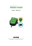
3-Ax xis Acce elerome eter MSE M ENS S-AC C User's Ma anuall 0 09-3, Yangno-ri, Bibong-myeon n, Hwaseong-sii, Gyeonggi-do, Korea [445-8442] http://www w.das-co.com TT) +82-31-356-3 3541, F) +82-31 1-356-3572 3-axis accelerometer MSENS-AC User’s manual Before using 1. This equipment is 3-axis, use the following information to be checked. 2. Check used to test the power. 10 ~ 30Vdc voltage is used. In noisy environments must be connected to the ground. 3. Connect the correct cable to determine the index, please. Incorrect connection may result in damage of the equipment. 4. 1 year warranty on this product. Applications 1. Navigation of vehicle, Speed detecting. 2. Earthquake Detection, Tilt measurement 3. Motion Control 4. Virtual Reality System Application 5. Measurement of the bridge safety inspection 6. vibration of Facilities, equipment and structures detection 2 3-axxis accelerom meter 1 MSEN NS-AC Useer’s manuaal MSE ENS-AC features f and spe ecificatio ons 1-1Features Main fu unction of MSENS-AC M i s measuring g 3-axis acce eleration witth included MEMS elemen nt. It provides best solu ution about any application by M icroprocesso or. The user se ettings can be stored i n internal memory m of sensor. (direection, the analog output range, the sensor ID, sspecify the initial value, etc.) In add dition, becau use the sensor RS-485 com mmunication n can be con nnected to more m than 11Km, a line can be conneccted to Maxximum 254 sensors. Co ore sensor shield s to prrevent pene etration through the strong g noise, mo otors, etc. ca an be used in strong n noise environment. Sensorss have been molded sili cone inside can be used d in incleme nt weather. 1-2 Size e Pic P 1.1 MSEN NS-AC Size 3 3-axis accelerometer MSENS-AC User’s manual 1-3Specifications Measuring Range ±2g , ±4g, ±8g : default is ±2g Core sensor - Sensitivity : ±2g= 1 mg/DIGIT ,±4g = 2 mg/DIGIT ,±8g = 3.9 mg/DIGIT - Zero -g level change vs temperature : - Typical zero-g level offset accuracy : ± 20mg - Sensitivity change vs temperature - Bandwidth(Hz) : 100 Hz ± 0.1mg / ˚C ( 0 to 70˚C ) : ±0.01 %/°C Power Typical : 12Vdc The sensor was unregulated power (10~30Vdc) supply is also available. Current : <50mA at 12Vdc Housing IP66, PVC Case, Water-proof Housing : The Sensor can be waterproof silicone molding. Operating Temperature -20 to .. +85°C Weight about 68g Cable 5P Shield cable, 50CM 4 3-axis accelerometer MSENS-AC User’s manual 2 Output 2-1 RS-485 Serial output (default 115200,8,1,n) format : Ex) [101234451923]54CR(’’ is space) [IDMODEXYZ]+Checksum+ CR 2-2 0~5V Voltage output. (default type) - Yellow cable through the output. - User can change output axis by serial command. - Lowest range : 100mV (It can be changed between 100 ~ 1,000mV by order made) - Highest range : 4900mV (It can be changed between 4000 ~ 4900mV by order made) - Center Value : middle value between Low output and High output 2-3 4~20mA Current output .(order made) - Yellow cable through the output. - User can change output axis by serial command. - Lowest range : 4.32mA - Highest range : 19.68mA - Center Value : 12mA. 5 3-axxis accelerom meter 3 MSEN NS-AC Useer’s manuaal Sensor ax xis directtions MSESE--AC measure e 3-axis acceeleration (X, Y, Z) 3-axis directions d are following. + -- X Y + + Pic 3.1 Each h axis direction Pic 3.2 3-axis directions 6 Z 3-axxis accelerom meter 4 MSEN NS-AC Useer’s manuaal Wiriing MSESE--AC for a fiv ve-stranded shielded ca able is used. Supply vo ltage 2-line,, RS485 2-line, mA ou utput consissts of a line e. RS-485 and the unu used line off mA ouch the otther by cutting the cable must be insulated. When W output does not to R distance is longeer than 50M 120 Ohm te ermination iss recommen nded. using RS-485 In addiition, if multiple sensorrs connected d in parallel to use in the termina ation resistorrs. 4-1RS-485 Wiring. RS-485 5 communications can b be read senssor value when the one or more sen nsors can be e connected in parallel tto a line. Ho owever, cauttion this tim me, each sen nsor's ID to be b different, continuouss data read (# READ) instruction, su uch as ID an nd to answerr all the sen nsors, regard dless of insttruction shou uld not be used. And when w you use multiple sensors to o allow sufficient powe er supply w wiring should d be designed. Pic 4.1 Cable index Pic 4.2 RS-4 485 Parallel connection c diagram d 7 3-axxis accelerom meter MSEN NS-AC Useer’s manuaal 4-2 Analog g wiring The an nalog output is voltage((default) or current c output. Outpu ut axis of ana alog is chang ged by userr command. The default output axis is Z. (mV) outt V GND Pic 4.3 3 Analog of voltage v wirin ng A GND 4 Analog of current c wirin ng Pic 4.4 Accele eration VS Voltage output 8 3-axis accelerometer MSENS-AC User’s manual 5 MSENS-AC Communication Commands First of all the transfer of 'CR' will be sent by appending. Example> In case ID = 1 , MODE = 0, Send format : <1 Command> + Check-sum + CR Receive format : [1 0 “X”“Y”“Z”] + Check-sum + CR Example of calculation checksum) <1 START> = ‘<‘ XOR ‘1‘ XOR ‘‘ XOR ‘S’ XOR ‘T’ XOR ‘A’ XOR ‘R’ XOR ‘T’ XOR ‘>’ = CHECK_SUM Command Data output Echo CMD VALUE Function Data output <1> x x 1time data [1 0 1234 45 4567] <1 START> [1 START] x Continues [1 0 1234 45 4567] data Setting Command <1 STOP> [1 STOP] x Stop output <1 ID 254> [1 ID 254] 1~254 ID Change <1 MODE 0> [1 MODE 0] Filter ON : 0 MODE RAW 값 : 1 Change 2, 4 ,8 Full Scale 2G, 4G, 8G Setting <1 SCALE 2> [1 SCALE 2] <1 ANALOG 2> [1 ANALOG 2] X:0, Y:1, Z:2 Analog Output axis choice <1 OFFSET 3.5> [1 OFFSET 3.5] Voltage(mV) Analog output axis offset <1 SPAN 1.05> [1 SPAN 1.05] Scale Analog output Factor span <1 SAVE> [1 SAVE] x Save Setting <1 RESTORE> [1 RESTORE] x Default setting values return <1 VER> [1 VER MSENS-AC 01.00] x Version information Table 5.1 Command 9 2G, 4G, 8G 3-axis accelerometer 5-1 MSENS-AC User’s manual One-time data output COMMAND <1> Function One-time data output Example (id=1) <1> Echo None Output [1 0 1234 45 1923] Attention) All of following example is for ID 1, MODE 1. Mode ’0’ Output data is applied Kalman filler. It is good for slow measurement and more correct value. Unit is mg/DIGIT. [10123445 1923] ex) 1234 = 1234 mg = 1.234 g ID=1, MODE=0, X=1234, Y=45, Z=1923 Mode ‘1’ Output data is not applied Kalman filler. It is good for fast and more roughly measurement. Unit is mg/DIGIT ex) 1234 = 1234 mg = 1.234 g Output is include scale value. [1 11 522 2345 1253] ID=1, MODE=1 ,SCALE=1,X=522, Y=2345, Z=1253 (Attention) When the Mode is ‘1’, output interval is 10msec. 10 3-axis accelerometer MSENS-AC User’s manual 5-2 Continuously data output COMMAND <1 START> Function Continuously data output Example (id=1) <1 START> Echo [1 START] Output(mode=0) [1 0 1234 45 1923] After send command, send the save command. If don’t send save command, lost command when turn off. Attention) Do not send ‘START’ command to more 2 device with RS485. 5-3 Stop data output COMMAND <1 STOP> Function Stop data output Example (id=1) <1 STOP> Echo [1 STOP] If output speed is high, Send ‘STOP’ command several times until data output is stop. 11 3-axis accelerometer MSENS-AC User’s manual 5-4 ID Setting COMMAND <1 ID “New ID”> Function ID Setting and check Default 1 Value “New id” Example (new id=123) <1 ID 123> Echo [1 ID 123] MSENS-AC has own ID number (1~254). Default ID number is ‘1’. You want know ID number, do following Connect to pc on RS45 and send <0>. The return value is ID,, MODE , X,Y,Z. [1 0 1234 45 1923] It mean is ID=1 , MODE=0, X=1234, Y=45, Z=1923 (Attention) After send command, send the save command. If don’t send save command, lost command when turn off. . 12 3-axis accelerometer MSENS-AC User’s manual 5-5 Data output type setting COMMAND <1 MODE “VALUE”> Function Data output type setting Value 0,1 Default 0 Example (new MODE=1) <1 MODE1> Echo [1 MODE1] It is setting data output type and check. Default value of MODE is ‘0’ MODE 0 : Output data is applied Kalman filler. It is good for slow measurement and more correct value. MODE 1 : Output data is not applied Kalman filler. It is good for fast and more roughly measurement. If you wand know what is the set MODE, Send <1 MODE>. Then return value is [1 MODE 0]. It mean is MODE 0. 5-6 Data output interval COMMAND <1 INTERVAL “VALUE”> Function Data output interval Value 10 ~ 1000 Default 100 Example (INTERVAL=10mS) <1 INTERVAL 10> Echo [1 INTERVAL 10] It is setting data output interval and check. The setting unit is msec. Range is from 10[msec] to 1000[msec]. Setting step is 10[msec]. Default value is 100 [msec. But, interval is only 10[msec] when MODE 1. Send Command : <1 INTERVAL> Return value : [1 INTERVAL 10] It mean is 10[msec]. 13 3-axis accelerometer 5-7 MSENS-AC User’s manual Full Scale Setting COMMAND <1 SCALE “VALUE”> Function FULL SCALE of acceleration setting Value 2, 4, 8 Default 1 Example (NEW SCALE=8) <1 SCALE 8> Echo [1 SCALE 8] It is setting Full scale of acceleration and check. SCALE mg 2 ±2000 4 ±4000 8 ±8000 Default value is 2(±2000 mg) If you want know SCALE, Send <1 SCALE>. Return value is [1 SCALE 8]. It mean is 8(±8000 mg). 5-8 Baudrate of serial COMMAND <1 SPEED “VALUE”> Function RS485 serial baudrate setting Value 1, 2, 3 Default 1 Example (SPEED=2) <1 SPEED 2> Echo [1 SPEED 2] It is setting baudrate of RS485 and check.. Default value is Baudrate:115200, Data bit:8, Stop bit:1, parity:None SPEED BAUD RATE 1 115200 2 57600 3 38400 If you wand know what is baudrate value, send <1 SPEED >. Return value is [1 SPEED 1]. It mean is 115200(baudrate is 115200). 14 3-axis accelerometer MSENS-AC User’s manual 5-9 Axis of analog output setting COMMAND <1 ANALOG “VALUE”> Function Axis of analog output setting Value 0, 1, 2 Default 2 Example (ANALOG=0) <1 ANALOG 0> Echo [1 ANALOG 0] It is setting axis of analog output and check. Default value is 2(Z axis). ANALOG AXIS 0 X 1 Y 2 Z If you want know what is output axis of analog. Send <1 ANALOG>. Return value is [1 ANALOG 0]. Analog value is deferent depend on FULL SCALE. ±2g : -2g : 0.5V, 0g : 2.5V, +2g : 4.5V 출력. ±8g : -8g : 0.5V, 0g : 2.5V, +8g : 4.5V 출력 4~20 mA : 0.5V = 5.6 mA, 2.5V = 12 mA, 4.5V = 18.4 mA 5-10 Analog output offset setting COMMAND <1 OFFSET“VALUE”> Function Analog output offset setting Value Real Default 0 Example (OFFSET=3.5) <1 OFFSET 3.5> Echo [1 OFFSET 3.5] 15 3-axis accelerometer MSENS-AC User’s manual It is setting for analog output offset and check. Default value is 0[mV]. It has two kind of type. One of them is voltage, other one is current. It is setting by order made. Default is voltage. If sensor is current output type and setting value is 1, output is change to 3.2uA up. Example) <1 OFFSET 3.5> 3,5mV up. <1 OFFSET -12.5> -12.5mV down. If you want know what is offset setting value, send <1 OFFSET>. Return value is [1 OFFSET -12.5]. It means offset setting value is -12.5 mV. 5-11 Span of analog output setting COMMAND <1 SPAN“VALUE”> Function Span of analog output setting Value Real Default 1 Example (SPAN=1.00452) <1 SPAN1.00452> Echo [1 SPAN1.00452] It is setting for span of analog (mV or mA) output and check. Default value is 1. Example) <1 SPAN 1.00452> Voltage output is FULL SCALE * 1.00452 <1 SPAN 0.9987> Voltage output is FULL SCALE * 0.9987 If you wand know what is SPAN setting value, Send <1 SPAN. Return value is [1 SPAN0.9987 5-12 Save setting values COMMAND <1 SAVE> Function Save setting values Example <1 SAVE> Echo [1 SAVE] It is to save to EEPROM setting values. 16 3-axis accelerometer MSENS-AC User’s manual 5-13 Conform the S/W version COMMAND <1 VER> Function Conform the S/W version Example <1 VER> 응 답 [1 VER MSENS-AC 01.00] If you want know what is S/W version, send <1 VER> Return value is [1 VER MSENS-AC 01.0]. 5-14 Return all setting values to default COMMAND <1 RESTORE> Function Return all setting values to default Example <1 RESTORE> Echo [1 RESTORE] All setting values in EEPROM are return to default except baudrate. 17 meter 3-axxis accelerom MSEN NS-AC Useer’s manuaal 6 Install PC Pro ogram 6-1Downlo oad pc pro ogram The settup program m is technica l board of DAS D homepa age( http://w www.das-co.ccom). 6-2 Install Double clicck the icon of o setup. Input the install path. Finish 18 3-axxis accelerom meter MSEN NS-AC Useer’s manuaal 7MSENS-Viewer Main window w 7-1MAIN MSENS-AC MSENS-GY Iff you wan nt more in nformation n about program, p please see e the m manual of MSENS-V Viewer. 19 3-axis accelerometer MSENS-AC User’s manual The information contained in the product manual without prior notice for quality improvement. Described above are subject to change copyright of all content on DAS CO.,LTD And reproduced without prior consent, and may not be distributed by. DAS Co., Ltd Copyright ⓒ by Das Co.,Ltd. All Right Reserved Website : www.das-co.com Phone No : +82 - (0)31 - 356 - 3541 FAX No : +82 - (0)31 – 356 - 3572 e-mail : Address : 09-3, Yangno-ri, Bibong-myeon, Hwaseong-si, Gyeonggi-do, Korea [email protected] [445-842] 20