1
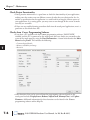
MAINTENANCE
CHAPTER
7
In This Chapter...
Project Backup ......................................................................................................... 7-2
Check Operating Environment ................................................................................. 7-2
Check Operating Voltage ......................................................................................... 7-2
Check Status Indicators ............................................................................................ 7-2
Check Physical Conditions ........................................................................................ 7-3
Run Tests under System Setup Screens ..................................................................... 7-3
Check Memory Usage .............................................................................................. 7-4
Check/Adjust Display Brightness............................................................................... 7-4
Check Error Log ...................................................................................................... 7-4
Adjust Touch Panel................................................................................................... 7-4
Cleaning the Display Screen ..................................................................................... 7-5
Check Project Functionality ...................................................................................... 7-6
Checks from C-more Programming Software ............................................................ 7-6
Notes: ......................................................................................................................... 7-7
Chapter 7 - Maintenance
Maintenance
1
2
3
4
5
6
7
8
9
10
11
12
13
14
A
B
C
D
Although the C-more touch panels require very little maintenance, setting up a routine
maintenance schedule will ensure the longevity of the product in your application.
The following are some suggestions of items to include in a preventive maintenance list or
schedule. Most of these items should be scheduled quarterly or semi-annually.
Project Backup
• During routine preventive maintenance is a good time to make sure that there is an up-todate backup of the application project. Although the C-more touch panel has the ability to
upload the complete project from a panel through the programming software, insurance
is warranted just in case the worse case scenario happens and the entire touch panel is
destroyed.
Check Operating Environment
• Make sure the touch panel is operating in the proper temperature range:
0 to 50 °C (32 to 122 °F).
• Make sure the touch panel is operating within the specified humidity range:
(5 – 95% RH, non-condensing).
• Make sure the operating environment is free of corrosive gasses.
CORROSIVE
8
Check Operating Voltage
• Check the input voltage that is powering the touch panel to make sure it is within the
appropriate range.
DC: 12 - 24 VDC
AC: If the panel is being powered from an AC/DC Power Adapter, EA-AC, then the
acceptable input voltage range to the adapter is 100-240 VAC, 50/60 Hertz.
Check Status Indicators
• During routine maintenance is a good time to take a quick look at the status indicators on
the front and rear of the touch panel. The Power LED (PWR) indicator should be on and
there should be activity on the TxD and RxD LED indicators when connected serially to
a PLC or control device. Check the status of the CPU LED and compare it to the chart
shown in the illustration below. Any indication of the CPU LED other than a solid green
shows there is a possible problem, and the condition needs to be corrected.
Power LED (Green)
On
Power On
Off
Power Off
CPU Status LED (Green, Orange & Red)
Off
Green
Red
User Defined LED (Green, Orange & Red)
CPU
Off
Red
Orange
User Defined
(Refer to online help
file for further details)
Port3
TxD
RxD
Blinking
Red
Blinking
Orange
Blinking
Green
Port1 RxD
Memory Error
Watchdog Timer Error
OS Error
Power Loss Detection
TxD
Serial TxD/RxD LED (Green)
On Comm. is active
Off No communication
Front View
7-2
Port2
TxD
RxD
Green
Blinking
Red
Blinking
Orange
Blinking
Green
Power Off
Normal – CPU Run State
®
Rear View
EA9-USER-M Hardware User Manual, 1st Ed. Rev B 01/15
Chapter 7 - Maintenance
Check Physical Conditions
• Make sure that harmful chemicals are not being used around the panel. Look for any
deterioration of the touch panel’s bezel and front display area.
• Check the mounting gasket to make sure it is sealing properly and has not deteriorated.
Replace the mounting gasket if there are any signs of
deterioration, or if there is any evidence that moisture/liquids
have penetrated to the inside of the enclosure where the panel is
mounted. Information on a replacement gaskets can be found in
Chapter 9: Replacement Parts.
p/n EA-xx-GSK
• Check to make sure that none of the cooling vents around the
inside section of the touch panel are clogged with dust or debris. Also make sure that there is
clearance around the touch panel as shown in Chapter 4: Installation and Wiring.
Run Tests under System Setup Screens
• Use the touch panel’s System Setup Screens to test the touch
screen, display, communication ports, beeper and audio output
(only with external amplifier and speaker(s) connected). See
Chapter 5: System Setup Screens for additional details for the
Test Menu.
Test Touch Panel - allows the user to check the analog
touch function of the screen by drawing free hand lines
and shapes across the entire touch area. The display will
retain the lines where the screen has been touched until the
Cancel button is pressed.
Test Display - used to test the display and color rendition. A test pattern will first
show both the primary colors and a gray scale. If the touch screen is not pressed within
a few seconds, the display will go into alternating color sweeps across the screen until
the panel is pressed again. If the screen is pressed when the test pattern first appears, it
will stay in this mode until the Cancel button is pressed.
Test Comm. Port - used to test the functionality of the 15-pin PLC communication
serial port, the 3-wire terminal block RS-485 port, the RJ12 RS-232 port and the
Ethernet port. A loop-back connector can be fabricated and used on the serial ports
to test the RS-232 or RS-422/485 communications for the TxD and RxD signals and
also the RTS and CTS signals if applicable. The Test Comm. Port setup screens and
Chapter 5 show pin-outs for the RS-232 and RS-422/485 loop-back connectors. The
Ethernet connection can also be tested for communications if it is at least connected
to an Ethernet switch. If the touch panel is connected to a PLC, then an inquiry test
can also be done to test the communications between the panel and the PLC. Press the
Cancel button when finished to return to the Test Menu screen.
Test Beep/Sound - used to test the touch panel’s internal beeper and also test the
audio line output port with an external amplifier and speaker(s) connected. Testing
the audio output is done by playing an included internal WAV file. Press the Cancel
button when finished to return to the Test Menu screen.
EA9-USER-M Hardware User Manual, 1st Ed. Rev B 01/15
®
1
2
3
4
5
6
7
8
9
10
11
12
13
14
A
B
C
D
7-3
Chapter 7 - Maintenance
Check Memory Usage
1
2
3
4
5
6
7
8
9
10
11
12
13
14
A
B
C
D
7-4
• A good time to check and record the touch panel’s memory
usage for future reference is during a routine maintenance
schedule. The various memory devices being used by the panel
are listed under the tab. This includes internal memory as well
as any external memory device such as a USB pen drive or SD
card memory. If no external memory device is inserted, it will
not show up on the list.
• The memory usage can be viewed by use of the panel’s
System Setup Screen’s Main Menu, and then selecting the
Information button then the Memory tab. See Chapter 5:
System Setup Screens for additional details on using the
Memory tab.
Check/Adjust Display Brightness
• Is is good practice to occasionally check the display brightness
or contrast and adjust as required. This is done by using the
Setting Menu in the System Setup Screens. See Chapter 5:
System Setup Screens for additional details.
Check Error Log
• Another good practice is to review the touch panel’s Error
Log. The log can be viewed by use of the panel’s System
Setup Screen’s Main Menu, and then selecting the
Information button. Look under the Error tab. See Chapter
5: System Setup Screens for additional details on using the
Error tab, Appendix A: PLC Protocol Error Codes for a
list of the error codes as they relate to the specific PLC that
is being used with a description of the error, and Appendix
B: Touch Panel Runtime Errors for a list of errors that may
occur when the panel is in operation.
Adjust Touch Panel
• It is recommended that a regularly scheduled maintenance
program include adjusting the touch panel. The adjustment
calibrates the touch area of the panel. The procedure should
also be done anytime that it seems the touch area being
pressed for an object is out of position by a small amount. The
procedure is done by using the Setting Menu in the System
Setup Screens and then selecting the Adjust Touch Panel
button. See Chapter 5: System Setup Screens for additional
details.
®
EA9-USER-M Hardware User Manual, 1st Ed. Rev B 01/15
Chapter 7 - Maintenance
Cleaning the Display Screen
• The display screen should be cleaned periodically by wiping
it with a lint free damp cloth using a mild soap solution.
Dry the surface when finished with a lint free cloth. Do not
clean with ammonia based products which are solvents and
will damage the face of the panel.
• The longevity of the display can be increased by the use of
a non-glare screen protector, p/n EA-XX-COV2, where XX
EA-6-COV2
= touch panel screen size, 6, 8, 10, 12, or 15. See Chapter
3: Accessories for additional information on the screen
protectors.
• To prevent damage to the display screen, avoid touching the screen with sharp objects,
striking the screen with a hard object, the use of abrasives near the screen, or using excessive
force when pressing the touch screen.
EA9-USER-M Hardware User Manual, 1st Ed. Rev B 01/15
®
1
2
3
4
5
6
7
8
9
10
11
12
13
14
A
B
C
D
7-5
Chapter 7 - Maintenance
Check Project Functionality
1
2
3
4
5
6
7
8
9
10
11
12
13
14
A
B
C
D
7-6
• During routine maintenance is a good time to check the functionality of your application,
making sure that various areas on different screens do what they were designed to do. An
outline or specification for the application is a useful tool for testing the various aspects of
your application. As a starting point, you may want to run through all the screens to make
sure they are accessible.
• If there are any trouble-shooting procedures built into the touch panel application, now is a
good time to also check these aids.
Checks from C-more Programming Software
• If you have a PC available with the C-more programming software, EA9-PGMSW,
installed, and the PC is connected to the touch panel, there are checks you can make to the
status of the touch panel by using the Panel Information... feature located under the Main
Menu heading Panel. This includes the following:
• Connected panel details
• Memory availability and usage
• Revisions
• Other functions that can be accessed from the programming software directly to the
touch panel include: DisplayScreen, Reboot, AdjustClock, MemoryClear, and Update
Firmware. Additional information for these functions can be found in the C-more
programming software online help file.
®
EA9-USER-M Hardware User Manual, 1st Ed. Rev B 01/15
Chapter 7 - Maintenance
Notes:
_____________________________________________________________
_____________________________________________________________
_____________________________________________________________
_____________________________________________________________
____________________________________________________________
_____________________________________________________________
____________________________________________________________
_____________________________________________________________
_____________________________________________________________
_____________________________________________________________
_____________________________________________________________
_____________________________________________________________
_____________________________________________________________
_____________________________________________________________
_____________________________________________________________
_____________________________________________________________
_____________________________________________________________
_____________________________________________________________
_____________________________________________________________
_____________________________________________________________
_____________________________________________________________
_____________________________________________________________
_____________________________________________________________
_____________________________________________________________
____________________________________________________________
_____________________________________________________________
_____________________________________________________________
_____________________________________________________________
_____________________________________________________________
_____________________________________________________________
_____________________________________________________________
____________________________________________________________
_____________________________________________________________
EA9-USER-M Hardware User Manual, 1st Ed. Rev B 01/15
®
1
2
3
4
5
6
7
8
9
10
11
12
13
14
A
B
C
D
7-7