1
9300 JSDA series AC SERVO SYSTEM Instruction Manual ■Warning and Alert:
Warning
y
Do not proceed to the assembly of the line while electrifying.
y
Circuit & change components between entering shutting down the power supply and stopping
showing CHARGE LED light of the Servo driver.
y
The output of Servo drive [U, V, W] must NOT touch the AC power.
!
Alert
y
Install the fan if the temperature around is too high while the Servo driver is installed in the
Control Board.
y
Do not proceed to the Anti-Pressure-Test to the Servo driver.
y
Confirm the quick stop function is available before operate servo drive.
y
Matching up machine to change the user parameter setting before machine performs. If there is
no according correct setting number, it could lead to out of control or breakdown.
Safety proceeding:
Check the covering letter detail before installing, running, maintaining and examining. Furthermore, only
the profession-qualified people can proceed to the line-assembly.
Safety proceeding in the covering letter discriminate between “Warning”&”Alert”.
Alarm
Indicating the possibility dangerous situation. It could cause the death or serious
damage if being ignored.
Indicating the possibility dangerous situation. It could cause smaller or lighter human
!
Warning
injured and damage of equipment.
Read this covering letter detail before using Servo driver.
i
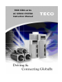
First of all, thank you for using TECO Servo Driver JADA Series (“JSDA” for short) and Servo Motors.
JSDA can be controlled by digital board or PC, and provide excellent performance for a wide range of
applications and different requirement from customers.
Read this covering letter before using JSDA. Contents of the letter comprises:
y
Servo System checking, installing and procedure of assembly line.
y
Controller procedure for digital board, status displaying, unusual alarm and strategy explanation.
y
Servo System control function, running testing and procedures adjusted.
y
Explanation for all parameter of Servo Driver.
y
Standard specification of JSDA Series.
In order to daily examine, maintain and understand the reason of unusual situation and handle strategy,
please put this covering letter in safe place to read it anytime.
P.S: The end user should own this covering letter, in order to make the Servo Driver bring the best
performance .
ii
Contents
Chapter 1
Checking and Installing
1-1 Checking Products ..........................................................................................................................1-1
1-1-1 Confirming with Servo Drives ..............................................................................................1-1
1-1-2 Confirming with Servomotors..............................................................................................1-2
1-2 Surface and Panel Board ................................................................................................................1-3
1-3 A Brief Introduction of Operation for Drives.................................................................................1-4
1-4 Conditions for Installation of Drives..............................................................................................1-5
1-4-1 Environmental Conditions....................................................................................................1-5
1-4-2 Direction and Distance..........................................................................................................1-6
1-5 Conditions for Installation of Servomotors ..................................................................................1-7
1-5-1 Environmental Conditions....................................................................................................1-7
1-5-2 Method of Installation ...........................................................................................................1-7
1-5-3 Notice for in stall motor ........................................................................................................1-8
Chapter 2
Wiring
2-1 Basic Wiring for Servo System ......................................................................................................2-1
2-1-1 Wiring for Main Circuit and Peripheral Devices .................................................................2-1
2-1-2 Wiring for Servo Drives.........................................................................................................2-2
2-1-3 Specifications of Wiring........................................................................................................2-3
2-1-4 Motor Terminal Layout ..........................................................................................................2-4
2-1-5 Typical Wiring for Motor and Main Circuit ..........................................................................2-6
2-1-6 TB Terminal ............................................................................................................................2-7
2-1-7 Wiring for Mechanical Brake. ................................................................................................2-8
2-2 I/O Terminal ......................................................................................................................................2-9
2-2-1 Output Signals from the Servo pack .................................................................................2-10
2-2-2 Encoder Connector (CN2) Terminal Layout......................................................................2-23
2-3 Typical Circuit Wiring Examples. .................................................................................................2-25
2-3-1 Position Control Mode (Pe Mode) (Line Driver). .............................................................2-25
2-3-2 Position Control Mode (Pe Mode) (Open Collector). .......................................................2-26
2-3-3 Position Control Mode (Pi Mode).......................................................................................2-27
2-3-4 Speed Control Mode (S Mode). ..........................................................................................2-28
2-3-5 Torque Control Mode (T Mode). .........................................................................................2-29
Chapter 3
Panel Operator / Digital Operator
3-1 Panel Operator on the Drives. ........................................................................................................3-1
3-2 Signal Display. .................................................................................................................................3-6
3-2-1 Status Display. .......................................................................................................................3-6
3-2-2 Diagnosis. ..............................................................................................................................3-7
Chapter 4 Trial Operation
4-1 Trial Operation for Servomotor without Load...............................................................................4-2
4-2 Trial Operation for Servomotor without Load from Host Reference .........................................4-5
4-3 Trial Operation with the Servomotor Connected to the Machine ...............................................4-9
iii
Chapter 5 Control Functions
5-1 Control Mode Selection. .................................................................................................................5-1
5-2 Torque Mode ....................................................................................................................................5-2
5-2-1 Analog Ratio ..........................................................................................................................5-3
5-2-2 Adjusting the Reference Offset............................................................................................5-4
5-2-3 Linear Acceleration and Deceleration ................................................................................5-5
5-2-4 Output Direction ....................................................................................................................5-6
5-2-5 Internal Torque Limit .............................................................................................................5-7
5-2-6 Limiting Servomotor Speed during Torque Control ..........................................................5-7
5-2-7 Additional Torque Control Functions..................................................................................5-8
5-3 Speed Mode......................................................................................................................................5-9
5-3-1 Setting Parameters .............................................................................................................5-10
5-3-2 Analog Ratio ........................................................................................................................5-11
5-3-3 Adjusting the Reference Offset..........................................................................................5-11
5-3-4 Limiting Speed with Analog Reference .............................................................................5-12
5-3-5 Encoder Signal Output........................................................................................................5-12
5-3-6 Smoothing............................................................................................................................5-14
5-3-7 Definition of CW and CCW..................................................................................................5-17
5-3-8 Speed Loop Gain .................................................................................................................5-18
5-3-9 Notch Filter...........................................................................................................................5-19
5-3-10 Limiting Servomotor Torque during Speed Control .......................................................5-21
5-3-11
Gain Switched...................................................................................................................5-22
5-3-12
Other Functioins...............................................................................................................5-29
5-4 Position Mode ................................................................................................................................5-31
5-4-1 External Pulse Command ...................................................................................................5-32
5-4-2 Internal Position Command................................................................................................5-34
5-4-3 Electronic Gear ....................................................................................................................5-37
5-4-4 Smoothing Acceleration ....................................................................................................5-41
5-4-5 Definition of Direction .........................................................................................................5-42
5-4-6 Gain Adjustment ..................................................................................................................5-42
5-4-7 Deleting the Pulse Offset ....................................................................................................5-43
5-4-8 Original Home ......................................................................................................................5-44
5-4-9 Other Position Functions ...................................................................................................5-53
5-5 Gain Adjustment ............................................................................................................................5-54
5-5-1
Automatic Adjusting ...........................................................................................................5-57
5-5-2 Manual Adjusting.................................................................................................................5-60
5-5-3 Improving Resonance .........................................................................................................5-61
5-6 Other Functions.............................................................................................................................5-62
5-6-1 Programmable I/O Functions .............................................................................................5-62
5-6-2 Switching Control Mode .....................................................................................................5-65
5-6-3 Auxiliary Functions .............................................................................................................5-65
5-6-4 Brake Mode ..........................................................................................................................5-66
5-6-5 Timing Diagram of Mechanical Brake ...............................................................................5-66
iv
5-6-6 CW/CCW Inhibit Function ..................................................................................................5-68
5-6-7 Selecting the External Regeneration Resistor .................................................................5-69
5-6-8 Fan Setting ...........................................................................................................................5-73
5-6-9 Analog Monitor ....................................................................................................................5-73
5-6-10 Paramerter .........................................................................................................................5-74
Chapter 6 Parameter Function
6-1 Explanation of Parameter Group ..................................................................................................6-1
6-2 Parameter Display Table ................................................................................................................6-2
Chapter 7 Communications Function
7-1 RS232 & RS485
............................................................................................................................7-1
7-1-1 Communication wiring ...........................................................................................................7-1
7-1-2 RS232 Communication Protocol and Format .....................................................................7-2
7-1-3 Modbus communication protocol for RS-485 ....................................................................7-5
7-2 Communication Address table.....................................................................................................7-16
Chapter 8 Troubleshooting
8-1 Alarm Display Table.........................................................................................................................8-1
8-2 Troubleshooting of Alarm and Warning ........................................................................................8-3
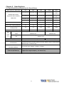
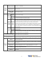
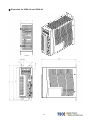
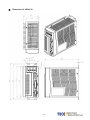
Chapter 9 Specifications
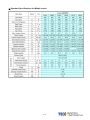
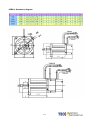
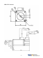
9-1 Specifications and Dimension for Servo Drives ........................................................................9-1
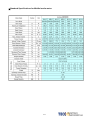
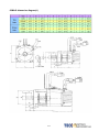
9-2 Specifications and Dimension for Servomotors ..........................................................................9-7
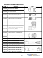
Appendix A - Peripheral for Servo motors ...................................................................... App-1
v
Chapter 1 Checking and Installing
1-1 Checking Products
Our Servo Pack have already completely been functionally examined before leaving the factory. In order to protect the
products from the damage during transportation, please check the items below before sealing off the pack:
y
Check if the models of servo driver and motor are the same with the models of ordering.
(About the model explanation, please check the chapters below)
y
Check if there are damage or scrape out side of the servo driver and motor.
(If there is any damage during transportation, do not power ON)
y
Check if there are any bad assembly or slipped component in the Servo Drive and Motor
y
Check if the Motor’s rotor and shaft can be rotated smoothly by hand
(The Servo Motor with Mechanical-Brake can not be rotated directly)
y
There must be the “QC”-seal in each servo drive, if not, please do not proceed Power ON.
If there is any bug or irregular under the situation above, please contact TECO’s Local sales representative or
distributor instantly.
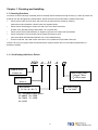
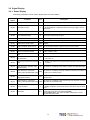
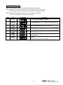
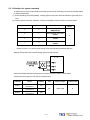
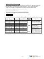
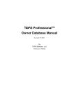
1-1-1 Confirming with Servo Drives
JSD A – 15
9300 AC Servo
Product No.
A
Input voltage phase:
□:Single / Three
3:3 Phase input
Drive Series:
Series A
Drive Model:
15 / 20 / 30 / 50 / 75
AC Input Voltage
A : AC 220V
P.S : Maximum output power
15 : 400 W 50 : 2 KW
20 : 750 W 75 : 3 KW
30 : 1 KW
1-1
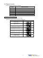
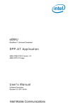
1-1-2 Confirming with Servo Motors
JSM
A – S C 30
A
H K
B
9300 AC Servo
Product No.
M:Machinery BK
: No BK
B:BK
Motor Series:
Series A
Encode Spline Grease Seal
Motor inertia:
S/T: Extra low
L: Low
M: Middle
Motor Speed:
A: 1000 rpm
B: 2000 rpm
C: 3000 rpm
H: 1500 rpm
No
No
K
Yes
No
O
No
Yes
A
Yes
Yes
Encolder:
B : 2500 ppr
H : 8192 ppr
Motor ratio power
02: 200 W
03: 300 W
04: 400 W
05: 550 W
08: 750W
10: 1 KW
15: 1.5 KW
20: 2 KW
30: 3 KW
1-2
AC input voltage
A:AC 220V
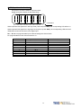
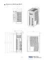
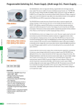
1-2 Surface and Panel Board
JSDA-15 / JSDA-20
JSDA-30
JSDA-50 / JSDA-75
Key Board
External Regenerative
Resistor Terminal
Internal Regenerative
Resistor Terminal
1-3
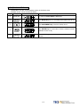
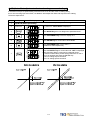
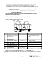
1-3 A Brief Introduction of Operation for Drives
There are many kinds of control-mode. The detail modes display as fellow:
Name
Position Mode
(External Pulse
Mode
Position control for the servo motor is achieved via an external
Pe
Command)
Position Mode
(Internal Position
Explanation
pulse command. Position command is input from CN1.
Position control for the servo motor is achieved via by 16
Pi
Command)
commands stored within the servo controller. Execution of the
16 positions is via Digital Input signals.
Single
Speed control for the servo motor can be achieved via
Mode
parameters set within the controller or from an external analog
Speed Mode
S
-10 ~ +10 Vdc command. Control of the internal speed
parameters is via the Digital Inputs. A maximum of three steps
speed can be stored internally.
Torque control for the servo motor can be achieved via
Torque Mode
T
parameters set or from an external analog -10 ~ +10 Vdc
command.
Multiple Mode
Pe-S
Pe and S can be switched by digital-input-contact-point.
Pe-T
Pe and T can be switched by digital-input-contact-point.
S-T
S and T can be switched by digital-input-contact-point.
1-4
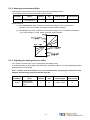
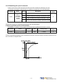
1-4 Conditions for Installation of Drives
1-4-1 Environmental Conditions
The product should be kept in the shipping carton before installation. In order to retain the warranty coverage, the
AC drive should be stored properly when it is not to be used for an extended period of time. Some storage suggestions
are:
y
Ambient Temperature: 0 ~ + 55 ℃; Ambient Humidity: Under 85% RH (Under the condition of no frost).
y
Stored Temperature: - 20 ~ + 85 ℃; Stored Humidity: Under 85%RH (Under the condition of no frost).
y
Vibrating: Under 0.5 G.
y
Do not mount the servo drive or motor in a location where temperatures and humidity will exceed specification.
y
To avoid the insolation.
y
To avoid the erosion of grease and salt.
y
To avoid the corrosive gases and liquids.
y
To avoid the invading of airborne dust or metallic particles.
y
When over 1 Drives are installed in control panel, enough space have to be kept to get enough air to prevent the
heat; the fan also must be installed, to keep the ambient temperature under 55 ℃.
y
Please Install the drive in a vertical position, face to the front, in order to prevent the heat.
y
To avoid the metal parts or other unnecessary things falling into the drive when installing.
y
The drive must be stable by M5 screws.
y
When there were the vibrating items nearby, please using vibration-absorber or installing anti-vibration- rubber, if
the vibration can not be avoided.
y
When there is any big-size magnetic switch, welding machines or other source of interference. Please install the
filter. When the filter is installed, we must install the insulation transformer.
1-5
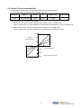
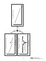
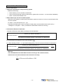
1-4-2 Direction and Distance
Fan
Fan
1-6
1-5 Conditions for Installation of Servo Motors
1-5-1 Environmental Conditions
y
Ambient Temperature: 0 ~ + 40 ℃; Ambient humidity: Under 90% RH (No Frost).
y
Storage Temperature: - 20 ~ + 60 ℃; Storage temperature: Under 90%RH (No Frost).
y
Vibration: Under 2.5 G.
y
In a well-ventilated and low humidity and dust location.
y
Do not store in a place subjected to corrosive gases, liquids, or airborne dust or metallic particles.
y
Do not mount the servo motor in a location where temperatures and humidity will exceed specification.
y
Do not mount the motor in a location where it will be subjected to high levels of electromagnetic radiation.
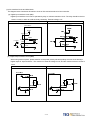
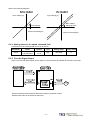
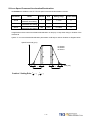
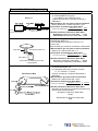
1-5-2 Method of Installation
1. Horizontal Install: Please let the cable-cavity downside to prevent the water or oil or other liquid flow into the servo
motor.
Attention
BRAKE
Encoder
2. Vertical Install: If the motor shaft is side-up installed and mounted to a gear box, please pay attention to and avoid the
oil leakage from the gear box.
1-7
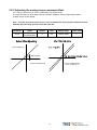
1-5-3 Notice for install motor
1. Please using oil-seal-motor to avoid the oil from reduction gear flowing into the motor through the motor shaft.
2. The cable need to be kept dry.
3. Please fixing the wiring cable certainly, to avoid the cable ablating or breaking.
4. The extending length of the shaft shall be enough, otherwise there will be the vibration from motor operating.
Wrong Example
Correct Example
5. Please do not beat the motor when installing or taking it apart. Otherwise the shaft and the encoder of backside will
be damaged.
Attention:
Brake
Encoder
1-8
Chapter 2 Wiring
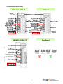
2-1 Basic Wiring for Servo System
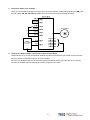
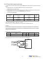
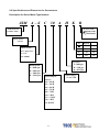
2-1-1 Wiring for Main Circuit and Peripheral Devices
200W~1KW Single Phase/3 Phase 200~230VAC
2KW~3KW 3 Phase 200~230VAC
No Fuse Break
PC
Noise Filter
Bectromagnetic
Contactor (MC)
PLC / PC BASE or
Motion Module
CN1
For I/O Connection
CN2
For Encoder Connection
External braking resistor is
connected to P and PC
Circuit between PC and P1 is
open
Servo motor
2-1
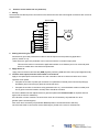
2-1-2 Wiring for Servo Drives
y
The wire material must go by “Wiring Specifications.”
y
Wiring Length: Command Input Wire: Less than 3m.
Encoder Input Wire: Less than 20m.
The Wiring goes by the shortest length.
y
Please wire according to the standard wiring schema. Don’t connect if no using.
y
Motor output terminal (U,V,W) must be connected correctly. Otherwise the servo motor will abnormally function.
y
Shielded cable must be connected to FG terminal.
y
Don’t install the capacitor or Noise Filter at the output terminal of servo drive.
y
At the control-output-signal relay, the direction of surge absorb diode must be correctly connected, otherwise it
can not output signal, and cause the protect loop of emergency-stop abnormal.
y
Please do these below to avoid the wrong operation from noise:
Please install devices such as the insulated transformer and noise filter at the input power.
Keep more than 30 cm between Power wire (power cable or motor cable…etc.) and signal cable, do not
install them in the same conduit.
y
Please set “emergency-stop switch” to prevent abnormal operation.
y
After wiring, check the connection-situation of each joint (ex: loose soldering, soldering point short, terminal order
incorrect…etc.). Tighten the joints to confirm if surly connected to the servo drive, if the screw is tight. There can
not be the situations such as cable break, cable pulled and dragged, or be heavily pressed.
* Especially pay attention to the polarity between servo motor wiring and encoder.
y
There is no necessary to add extra regeneration resistance under general situation. If there is any need or
problem, please connect to distributor or manufacturer.
2-2
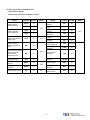
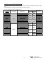
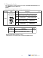
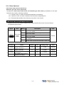
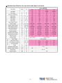
2-1-3 Specifications of Wiring
Connection Terminal
Connection
Terminal
TB
Terminal
Mark
(Sign)
Name of Connect
Terminal
JSDA-15
JSDA-20
JSDA-30
JSDA-50
JSDA-75
R, S, T
Main Power Terminal
2.0mm ²
A.W.G.14
2.0mm ²
A.W.G.14
2.0mm ²
A.W.G.14
2.0mm ²
A.W.G.14
3.5mm ²
A.W.G.12
U, V, W
Motor Terminal
2.0mm ²
A.W.G.14
2.0mm ²
A.W.G.14
2.0mm ²
A.W.G.14
2.0mm ²
A.W.G.14
3.5mm ²
A.W.G.12
r, s
Power-Control Terminal
1.25mm²
A.W.G.16
1.25mm²
A.W.G.16
1.25mm²
A.W.G.16
1.25mm²
A.W.G.16
1.25mm²
A.W.G.16
Ground
2.0mm ²
A.W.G.14
2.0mm ²
A.W.G.14
2.0mm ²
A.W.G.14
2.0mm ²
A.W.G.14
3.5mm ²
A.W.G.12
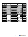
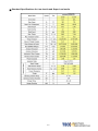
Connect Point Name
JSDA-15
JSDA-20
JSDA-30
JSDA-50
JSDA-75
1
FG
Connect
Terminal
Connect
Point No.
26,27,28
30,31
33,34
CN1
Joint
Control
Signal
Servo Drives and Wire Specifications
Speed / Torque
Command Input
Analog Monitor Output 1
0.2mm ² or 0.3mm ² -> Twisted-pair-cable connecting to the Analog
&2
Grounding wire (including shield cable)
Power Output +15V &
-15V
29,32,44
Analog Ground Terminal
1~13
General Analog Input
18~25,43
General Analog Output
45,46,
48,49
24V Power &
I/O Ground
14~17
Position Command Input
35~40
Encoder Signal Output
1,2
Output 5V
0.2mm ² or 0.3mm ² -> Twisted-pair-cable connecting to the I/O
Grounding wire (including shield cable)
0.2mm ² or 0.3mm ² -> Twisted-pair-cable (including shield cable)
CN2
Joint of
motor
encoder
RS232
Joint of
Communic
ation
3,4
Output Grounding wire of
0.2mm ² or 0.3mm ² -> Twisted-pair-cable (including shield cable)
power supply
5~18
Encoder Signal Input
2,3
Data transfer & receive
Communication
grounding wire
0.2mm ² or 0.3mm ² -> Twisted-pair-cable (including shield cable)
5
1,4,6,8
Floating
—
P.S.: 1. Please pay attention to the NFB and the capacity of noise filter when using multi ServoDrives.
2. CN1 ->50 Pins (3M Co.)
3. CN2 -> 20 Pins (3M Co.)
4. RS232 -> 9 Pins D-type Joint.
2-3
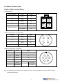
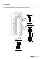
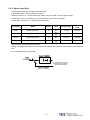
2-1-4 Motor Terminal Layout
A Table of Motor-Terminal Wiring
(1) General Joint:
Terminal Symbol
Color
Signal
1
Red
U
2
White
V
3
Black
W
4
Green
FG
Fine red
DC +24V
Fine yellow
0V
Brake control wire
(2)Military Specifications Joint (No Brake):
Terminal
Color
Signal
A
Red
U
B
White
V
C
Black
W
D
Green
FG
D
A
C
B
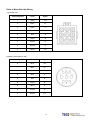
(3)Military Specifications Joint(Brake):
Terminal
Color
Signal
B
Red
U
G
White
V
E
Black
W
C
Green
FG
A
Fine red
F
Fine yellow
F
E
DC +24V
A
G
D
B
C
BK control wire
0V
P.S.: The military joint with BK of servo motor has 9 Pins; and the encoder joint has also 9 Pins. Please
confirm before wiring.
2-4
Table of Motor-Encoder Wiring
(1)General Joint:
Terminal Symbol
Color
Signal
1
White
+5V
2
Black
0V
3
Green
A
4
Blue
/A
5
Red
B
6
Purple
/B
7
Yellow
Z
8
Orange
/Z
9
Shield
FG
(2) Military Specifications Joint
Terminal Symbol
Color
Signal
B
White
+5V
I
Black
0V
A
Green
A
C
Blue
/A
H
Red
B
D
Purple
/B
G
Yellow
Z
E
Orange
/Z
F
Shield
FG
2-5
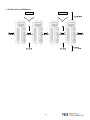
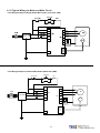
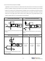
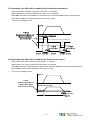
2-1-5 Typical Wiring for Motor and Main Circuit
* The Wiring Example of Single Phase Main Power (Less than 1KW)
* The Wiring Example of 3 Phase Main Power (More than 1KW)
Power ON
Power OFF
MC
MC/a
r
s
NFB
Power Filter
3 Phase 220V
MC/R
R
MC/S
S
MC/T
TB1
Red
V
White
W
TB1
T
U
FG
P
PC
CN2
FG
2-6
M
Black
Green
R
External
Regeneration
BK Resistance
PG
2-1-6 TB Terminal
Name
Terminal
Detail
Sign
Control circuit power input
r
terminal
s
Connecting to external AC Power.
Single Phase 200~230VAC +10 ~ -15% 50/60Hz ±5%
R
Main circuit power input
terminal
S
Connecting to external AC Power.
Single / 3 Phase 200~230VAC +10 ~ -15% 50/60Hz ±5%
T
External regeneration
resistance terminal
Regeneration terminal
common point
Internal regeneration
resistance terminal
Motor-power output
terminal
Motor-case grounding
terminal
P
P1
Please refer to Cn012 to see resistance value, when using external
regeneration resistance. After installing regeneration resistance, set the
resistance power in Cn012.
*If no using external regeneration resistance, PC-P1 need be close, P
doesn’t be connected.
*When using external regeneration, equip regeneration resistance
between PC-P, do not connect P1 terminal.
U
Motor terminal wire is red
V
Motor terminal wire is white
W
Motor terminal wire is black
FG
Motor terminal wire is green or yellow-green.
PC
2-7
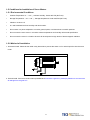
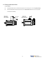
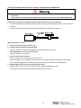
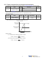
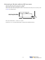
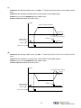
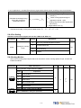
2-1-7 Wiring for Mechanical Brake
Uninstall BRAKE:
z
200/300/400/750W series: Use Red wire and yellow wire connecting to DC +24V voltage(No polarity)
z
550/1K/1.5K/2K/3KW series: BK outputs from A & C of Motor Power Joint, servo motor can operate
normally after uninstalling.
200/300/
400/750W
Yellow Wire
Red Wire
550/1K/
1.5K/2K/3KW
A
C
Encoder
Brake
Encoder
Brake
2-8
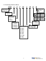
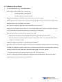
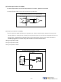
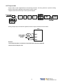
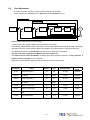
2-2 I/O Terminal
There are 3 groups of I/O terminal, which contain RS232 communication terminal, CN1 control signal terminal and
CN2 encoder terminal. The diagram below displays all positions for the terminal.
2-9
2-2-1 Output Signals from the Servopack
(1) Diagram of CN1 Terminal:
P.S.:
1. If there is unused terminal, please do not connect it or let it be the relay terminal.
2. The Shielded Wire of I/O cable should connect to the ground.
2-10
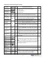
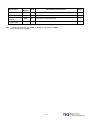
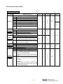
(2) CN1 Signal Name and Explanation:
(a) General I/O Signal:
Explanation of General I/O Signal Function
Signal
Position Pulse
Command Input
Position Symbol
Command Input
Open Collector
Position Command
Power Input.
Speed / Torque
Analog Command
Input
Torque Control Speed
Limit Command /
CCW Torque
Command Limit
CW Torque
Command Limit
Analog Monitor
Output 1
Analog Monitor
Output 2
Home Signal Output
Function
Symbol
Pin No.
Pulse
14
/Pulse
15
Sign
16
/Sign
17
OPC
41
Wired
Mode
IO3
IO3
Function
Symbol
Pin No.
PA
35
/PA
36
PB
37
/PB
38
PZ
39
/PZ
40
AG
29,32,44
+15V
33
-15V
34
DICOM
47
+24Vdc Output
IP24
45
+24Vdc Com
Terminal
IG24
46,48,49
Shielded Wire
Connect Point
FG
50
Signal
Encoder Output
A-Phase
Encoder Output / A
Phase
Encoder Output
B-Phase
Encoder Output
/B-Phase
Encoder Output
Z-Phase
/Z-Phase
SIN
Analog Signal
Ground Terminal
+15Vdc Output
Terminal
26
IO5
PIC
27
-15Vdc Output
Terminal
NIC
28
DigitaI input Com
Terminal
MON1
30
IO6
MON2
31
ZO
43
IO2
2-11
Wired
Mode
IO4
Explanation of General I/O Signal Function
Signal Name
Position Pulse
Command Input
Position Sign
Command Input
Open Collect
Position Command
PW Input
Speed Analog
command Input
Function
Mode
Symbol
Pulse
/Pulse
Sign
OPC
SIN
PIC
CCW Torque Limit
Command
NIC
Analog Monitor
Output 1
MON1
Analog Monitor
Output 2
MON2
The Driver can receive 3 kinds of Command below:
. (Pulse)+ (Sign)
. (CCW)/ (CW)Pulse
Pe
When open collect input in position command, OPC and IP24
can be close, and using internal 24V power and resistor.
/PB
ZO
ALL Z Phase Open Collector output connect point.
Analog Signal
Ground Terminal
AG
ALL
DI PW Conmen
5-4-1
―
5-3-1
In Speed Mode, when external speed command is operated at
5-3-2
S SPD1=0, SPD2=0, input the voltage range: -10V~+10V, Sn216
5-3-3
can be set input voltage: ±10V’s Motor output speed.
5-3-4
In Torque Mode, input the voltage range -10~+10V, Tn103 can 5-2-1
T
be set input voltage ±10V’s motor output torque.
5-2-2
In Torque Mode, when external speed limit is operated at input
T connect point SPD1=0 & SDP2=0(P.S), input voltage range: 5-2-6
0~+10V, 10V’s speed limit stands for motor’s ratio speed.
In Speed Mode, when external torque limit is be used at input
connect point TLMT=1(P.S.) , input voltage range: 0~+10V, to
S
5-3-10
input 10V will limit the motor CCW torque having 300% of ratio
torque.
In Speed Mode, when external torque limit is be used at input
connect point TLMT=1(P.S.), input voltage range: -10~0V, to
5-3-10
S
input -10V will limit the motor CW torque have 300% of ratio
torque.
Operating the motor to control the current speed to transform
the voltage output in accordance with the rate (±10V/1.5 times
5-6-9
ALL
ratio speed) CCW stands for positive voltage, CW negative
voltage.
Operating the motor to control the current torque to transform
the voltage output in accordance with the rate (±10V/3.5 times
ALL
5-6-9
ratio torque) CCW torque stands for positive voltage, CW
negative voltage.
Encoder Output A
Phase
Encoder Output / A
Phase
Encoder Output B
Phase
Encoder Output / B
Phase
Encoder Output Z
Phase
Encoder Output / Z
Phase
Home Signal
Output
+15V PW Output
Terminal
-15V PW Output
Terminal
Chapter
.AB Phase pulse
/Sign
Torque Analog
Command Input
Torque Control
Speed Limit
Command
CW Torque Limit
Command
Pe
I/O Operation and Function
PA
/PA
PB
PZ
Outputting the Motor Encoder Signal through pulse per rotation
handle. The pulse quantity of every rotating can be set in
Cn005.
5-3-5
ALL
When “1” is set in Cn004, it is CCW rotation from the motor load
terminal direction, and A Phase gets 90 degree ahead B Phase.
Signal Output is Line Driver.
/PZ
+15V
-15V
DICOM
Analog signal grounding: CN1 - > Pin 26、27、28、30、31、
33、34.
―
―
ALL To provide ±15V output power (Max. 10mA), which can be used
in servo drive – external voltage command. Suggestion: Using
ALL the variable resistance which is more than 3kΩ.
―
ALL Digital input power supplement common terminal.
―
2-12
Signal Name
Function
Mode
Symbol
I/O Operation and Function
Chapter
Terminal
+24V PW Output
+24V PW Ground
Terminal
Shielded Wire
Connect Point
IP24
ALL +24V power output terminal(Max. 0.2A).
―
IG24
ALL +24V power grounding terminal
―
ALL Connect to Shield wire of signal cable.
―
FG
P.S.: “1” stands for “close loop with IG24”; “0” stands for “open loop with IG24”.
PW is abbreviation of Power
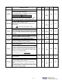
2-13
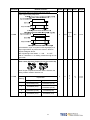
(b) Digital I/O Signal:
For many kinds of application, the digital input/output terminal layout of all operation mode are accordingly
different. In order to provide more functions, our drives can provide multi terminal layout settings. Users can set these
functions for application.
Digital input terminal layout provides 13 (Pin1~13) programmable terminal; digital output terminal provides 4
(Pin18~21) programmable terminals. The diagram below shows the default digital input/output terminal placement
and functions. Please refer to 5-6-1 to check related parameters setting.
Default Digital Input Terminal placement Functions and Wired Mode
Signal
Function
Sign
Pin
No.
Wired
Mode
Signal
Function
Sign
Pin
No.
Servo ON
DI-1
SON
1
Servo Lock
DI-8
LOK
8
Alarm reset
DI-2
ALRS
2
Emergency
Stop
DI-9
EMC
9
PI/P Switch
DI-3
PCNT
3
DI-10
SPD1
10
CCW
Operation Limit
DI-4
CCWL
4
DI-11
SPD2
11
CW
Operation Limit
DI-5
CWL
5
DI-12
MDC
12
External Torque
Limit
DI-6
TLMT
6
DI-13
SPDINV
13
Pulse error
amount delete
DI-7
CLR
7
IO1
Internal speed
command /
Limit select 1
Internal speed
command /
Limit select 2
Control Mode
Switch
Reverse
Direction
Speed
Command
Wired
Mode
IO1
―
Default Digital Input Terminal Layout Functions and Wired Mode
Signal
Function
Sign
Pin
No.
Wired
Mode
Signal
Function
Sign
Pin
No.
Servo ready
DO-1
RDY
18
Torque limit/
Alarm code A0
DO-5
LM/A0
22
Alarm
DO-2
ALM
19
P action /
Alarm code A1
DO-6
PC/A1
23
IO2
Wired
Mode
IO2
Zero speed
DO-3
ZS
20
Operation limit/
Alarm code A2
DO-7
ST/A2
24
Fix position
DO-4
INP
21
Base Block/
Alarm code A3
DO-8
BB/A3
25
2-14
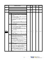
Digital Input Function
(Except CCWL and CWL are high electric potential, other terminal layout are low electric potential. Please refer
to 5-6-1 to see related parameters)
Signal Name
Function
Sign
Servo On
SON
Abnormal Reset
ALRS
PI/P switch
PCNT
CCW
Operation limit
CCWL
ALL
Connect to CCW over travel detector: CCWL and IG24 close loop;
open loop with IG24 -> CCW over travel operates.
CW
Operation limit
CWL
ALL
Connect to CW over travel detector: CWL and IG24 close loop;
open loop with IG24 -> CW over travel operates.
External torque
limit
TLMT
Pulse error
amount delete
CLR
Servo lock
LOK
S
Emergency stop
EMC
ALL
Internal speed
command / limit
select 1
Internal speed
command / limit
select 2
SPD1
SPD2
Mode
I/O Function
Chapter
SON and IG24 close loop: Servo ON ; SON and IG24 open loop:
Servo OFF. Attention: Before power on, the input connect point
SON (servo on) can not be operated to avoid danger.
ALRS and IG24 close loop: Relieving the stop-situation from of
abnormality. But the abnormality of encoder or memory will
ALL
cause the same alarm again. Please reset power after the
abnormality is eliminated.
PCNT and IG24 close loop will cause the speed loop control
Pi/Pe/S transforming to ratio control from ratio integration control.
ALL
5-6-3
5-6-4
8-1
5-3-11
5-4-8
5-6-3
5-6-4
5-4-8
5-6-3
5-6-4
TLMT and IG24 close loop will cause the motor-output-torque-limit
Pi/Pe/S to stay in the command-voltage range of
5-3-10
torque-limit-terminal-layout (PIC、NIC).
When CLR and IG24 close loop, delete the pulse amount in the
Pi/Pe Position Error Counter.
5-4-7
S/T
When LOK and IG24 close loop will transform speed control mode
5-3-12
into position control mode in order to lock the motor at the last
position.
When EMC and IG24 close loop: Emergency stop -> Servo Off and
exit the rotating statue, and Cn008 will decide if the dynamic Brake 5-6-4
operates.
SPD2
SPD1
Speed
Command
(Speed Mode)
Speed Limit
Command
(Torque Mode)
0
0
External
command(SIN)
External limit(PIC)
0
1
Sn201
Tn105
1
0
Sn202
Tn106
1
1
Sn203
Tn107
Internal speed setting and limit:
“1”: Close loop with IG24
“0”: Open loop with IG24
2-15
5-2-6
5-3-1
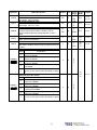
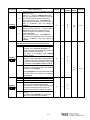
Digital Input Function Explanation
(Except CCWL and CWL are the high electric potential, other terminal layout are the low electric potential,
please refer to 5-6-1 to check related parameters setting)
Signal Name
Control Mode
Switch
Position
Command Limit
Speed Command
Counter Wise
Gain Select
Electric Gear ratio
Numerator 1~2
Internal Position
Command
Trigger
Internal Position
Command Hold
Function
Symbol
MDC
INH
SPDINV
G-SEL
GN1
GN2
PTRG
PHOLD
Home
SHOME
External Origin
ORG
Mode
I/O Function
When MDC and IG24 close loop, current control mode will
Pe/S/T transform into default control mode, please refer to Cn001.
When INH and IG24 close loop, position command input does
not operate (do not accept external pulse command).
When SPDINV and IG24 close loop in speed mode, setting
S
rotating speed will become counter-wise rotating speed.
When G-SEL and IG24 close loop, first stage control gain
Pi/Pe/S switch to the second control gain.
Electric gear ratio: select explanation:
Pe
Pi/Pe
GN2
0
0
1
1
GN1
0
1
0
1
Electric Gear ratio Numerator
Pn302
Pn303
Pn304
Pn305
“1”: Close loop with IG24
“0”: Open loop withIG24
When PTRG and IG24 close loop (positively-triggered), the
motor will select related position command to operate in
Pi
accordance with the terminal layout POS1~POS4.
When PHOLD and IG24 close loop(positively-triggered), the
Pi
motor will stay holding.
When SHOME and IG24 close loop(positively-triggered),
Pi/Pe
HOME function operates
When ORG and IG24 close loop(positively-triggered), server
Pi
will use this as external reference point for home position
returning.
2-16
Chapter
5-1
5-6-2
5-4-1
5-3-7
5-3-11
5-4-3
5-4-8
5-4-8
5-4-8
5-4-8
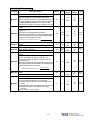
Digital Input Function Explanation
(Except CCWL and CWL are the high electric potential, other terminal layout are the low electric potential,
please refer to 5-6-1 to check related parameters setting)
Signal Name
Function
Symbol
Mode
I/O Function
Chapter
Internal position command select :
Internal Position
Command select
1~4
POS1
POS2
POS3
POS4
Pi
POS1
POS2
POS3
POS4
0
0
0
0
0
0
0
0
1
1
1
1
1
1
1
1
0
0
0
0
1
1
1
1
0
0
0
0
1
1
1
1
0
0
1
1
0
0
1
1
0
0
1
1
0
0
1
1
0
1
0
1
0
1
0
1
0
1
0
1
0
1
0
1
Internal Position
Command select
Pn317, Pn318
Pn320, Pn321
Pn323, Pn324
Pn326, Pn327
Pn329, Pn330
Pn332, Pn333
Pn335, Pn336
Pn338, Pn339
Pn341, Pn342
Pn344, Pn345
Pn347, Pn348
Pn350, Pn351
Pn353, Pn354
Pn356, Pn357
Pn359, Pn360
Pn362, Pn363
5-4-2
Internal position command select explanation:
“1”: close loop with IG24
“0”: open loop with IG24
Torque Command
Counter Clock TRQINV
Wise
T
When TRQINV and IG24 close loop in torque mode, setting
torque command output wise becomes counter wise output.
2-17
5-2-4
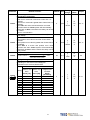
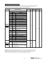
Digital Output Function Explanation
(The terminal layout here from this explanation are all the low electric potential, please refer to 5-6-1 to check
parameter settings)
Signal Name
Function
Symbol
Servo Ready
RDY
Alarm
ALM
Zero Speed
ZS
BK Signal
BI
In Speed
INS
In Position
INP
Home
HOME
Limiting Torque/
Alarm No. 0
LM/A0
P in Action /
Alarm No.1
PC/A1
Mode
I/O Function
Chapter
Main power and control power input are normal. Under the
―
situation of no alarm, terminal layouts RDY and IG24 close
loop.
If normally operates, the terminal layouts ALM and IG24 open
ALL loop. When alarm occurs, protection-function operates, the
―
terminal and IG24 close loop.
When the motor speed is less than the speed from Sn215, the
5-3-12
S
terminal layout ZS and IG24 close loop.
When Cn008 is set “1” or “3” and the servo on, the terminal
layout BI and IG24 close loop; when servo off , terminal layout
5-6-4
ALL and IG24 open loop. (When this terminal layout is generally
5-6-5
applied, it is the Brake relay, which is connected to control
motor).
When the motor speed has achieved the setting speed from
5-3-12
S
Cn007, INS and IG24 close loop.
When the amount of position error counter is less than the
5-4-9
Pi/Pe
amount range which is set in Pn307, INP and IG24 close loop.
Pi/Pe When HOME is accomplished, HOME and IG24 close.
5-4-8
When motor output torque is limited by internal torque limit
amount (Cn010&Cn011) or external torque limit command
ALL (PIC&NIC). LM/A0 and IG24 close loop.
8-1
When alarm occurs, this terminal layout is alarm code output
A0.
When speed loop is ratio(P)-control, PC/A1 and IG24 close
loop.
Pe/Pi/S
8-1
When alarm occurs, this terminal layout is alarm code output
A1.
ALL
Server in Limiting/
Alarm No.2
ST/A2
ALL
Base Block/
Alarm No.3
BB/A3
ALL
When CCW or CW operation-limit occurs, ST/A2 and IG24 close loop.
When alarm occurs, this terminal layout is alarm code output A2
When servo motor has not be operated, BB/A3 and IG24 close
loop.
When alarm occurs, this terminal layout is alarm code output A3
2-18
8-1
8-1
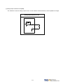
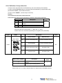
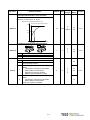
(3) CN1 Interface Circuit and Wire Mode:
The diagram below introduces all interface circuit of CN1 and wire-method of host controller.
(a) Digital input interface circuit (IO1):
Digital input interface circuit can be operated by relay or collector transistor circuit. The relay should be the low
electric current, in order to avoid the faulty contacting. External voltage: 24V.
Internal 24V Power
External 24V Power
Servo Driver
DC24V
IP24
CN1-45
CN1-47
i=4.3mA
5.6KΩ
DICOM
SON
CN1-49
IG24
(b) Digital Output Interface Circuit(IO2):
When using external power, please attention to the power polarity. Adverse polarity will case circuit damage.
Digital output is “Open Collector”. The maximum of external voltage is 24V; and the maximum electric current is
10mA.
Internal 24V Power
External 24V Power
2-19
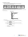
(c) Pulse Command Input Interface Circuit(IO3):
Suggesting to use the input method of Line Driver to send the pulse command. The maximum input command
frequency is 500kpps. Using the input method of Open Collector will cause the decrease of input command
frequency, the maximum input command frequency is 200kpps. The servo provides only 24V power, and other
power should be prepared. Adverse polarity of power will cause the servo damage. The maximum of External
power (Vcc) is 24V limited. Input current is about 8~15mA. Please refer to the examples below to select
resistance. Please refer to 5-4-1 to check pulse input command timing.
Line Driver pulse command input
The max. frequency of line driver type pulse command
is 500kpps
Open Collector pulse command input
Maximum input command frequency of open collector is
200kpps
Open Collector (Internal 24V)
Open Collector – Selection of input Resistance
Servo Driver
DC24V
IP24
CN1-45
CN1-41
OPC
2KΩ
330Ω
Pulse
Sign
External Power
External Power
External Power
Vcc=24V
Vcc=12V
Vcc=5V
R=2KΩ
R=750Ω
R=100Ω
1KΩ
/Pulse
/Sign
CN1-49
IG24
The maximum input command frequency of open
collector is 200kpps
2-20
(d) Encoder Output Interface Circuit (IO4):
Encoder output interface circuit is the output method of Line Driver, please let end terminal
resistance(R=200~330Ω) connect to Line Receiver input terminal.
Encoder Output Interface Circuit (Line Driver)
(e) Analog Input Interface Circuit(IO5):
There is sometimes ripple inside the servo internal power. Adverse external power polarity will cause severe
damage. Maximum external power voltage (Vc) should be less than12V; terminal input voltage should not more
than10V. Over voltage will cause damage. When using internal power of server, user need to choose the
resistance(suggestion: more than 3KΩ), which maximum current is less than 10mA.
SIN Input impedance: 15KΩ
PIC Input impedance: 40KΩ
NIC Input impedance: 20KΩ
Analog Input Interface Circuit
2-21
(f) Analog Output Interface Circuit(IO6):
The maximum current of analog output is 5mA, so user need to choose the device, which Impedance is larger.
Analog Input Interface Circuit
Servo Driver
TG
V
AG
2-22
2-2-2 Encoder Connector (CN2) Terminal Layout
(1) Diagram of CN2 Terminal:
(a) Diagram of Fewer Wiring Type Encoder:
(b) Diagram of non-Fewer Wiring Type Encoder:
P.S.: Do not wire to the terminal, which is un-operated.
2-23
(2) Name and Explanation of I/O Signal:
Encoder Output
No. and Color
Pin
No.
Signal Name
Code
General
Joint
9 wires
(fewer
wiring)
Plug-in
Joint
15 wires
Output
(non-fewer
No.
wiring)
1
2
Power output
+ Terminal
+5V
white
Red
B
3
4
Power output
- Terminal
0V
Black
Black
I
A
Green
A
/A
Blue
C
B
Red
Green
Green
White
Gray
/B
Pink
Gray white
D
Z
Yellow
G
/Z
Orange
V
Yellow
Yellow
white
Brown
Brown
white
Blue
/V
Blue white
W
Orange
Orange
white
5
6
7
8
9
10
11
12
13
14
15
16
A Phase encoder
input A
B Phase encoder
input
Z Phase encoder
input
U Phase encoder
input
V Phase encoder
input
W Phase encoder
input
17
18
19
No operated
20
Shielded wire
terminal layout
U
/U
/W
Terminal Layout Function
H
E
5V Power for encoder (provided from driver).
When the cable is more than 20m, user should
separately use 2 cables to avoid decreasing
voltage of encoder. When the cable is more
than 30m, please contact to the distributorship.
Encoder A Phase: From motor terminal to the
driver.
Encoder B Phase: From motor terminal to the
driver.
Encoder Z Phase: From motor terminal to the
driver.
When using fewer-wiring-type motor, do
not wire.
When using fewer-wiring-type motor, do
not wire.
When using fewer-wiring-type motor, do
not wire.
Do not wire.
FG
Shielded net wire
F
2-24
Shielded wire, which is connected to the signal
wire.
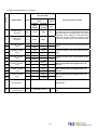
2-3 Typical Circuit Wiring Examples
2-3-1 Position Control Mode (Pe Mode) (Line Driver)
Pe mode =External pulse positioning command
2-25
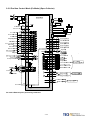
2-3-2 Position Control Mode (Pe Mode) (Open Collector)
Pe mode =External pulse positioning command
2-26
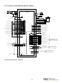
2-3-3 Position Control Mode (Pe Mode) (Pi Mode)
NFB
R
R
Supply
Filter
S
T
S
T
SERVO
FG
Digital input common
IP24
DICOM
PC
Regeneration resistor
P
PC
P1
DC 24V
Internal +24V DC
RS232
C
N
4
r
s
45
U
47
SERVO
MOTOR
V
Servo ON ( SON)
CCW Limit ( CCWL)
CW Limit ( CWL)
Emergency stop ( EMC)
HOME ( SHOME)
External Torque Limit ( TLMT)
Position Trigger ( PTRG)
Alarm Clear ( ALRS)
Position Hold ( PHOLD)
Position Select 1 ( POS1)
Position Select 2 ( POS2)
+24V ground
CCW Torque Limit
Analog Grounding
CW Torque Limit
Shield ground
DI-1
1
DI-4
4
DI-5
5
DI-9
9
DI-3
3
DI-6
6
DI-12
12
DI-2
2
DI-8
8
DI-10
10
DI-11
IG24
PIC
AG
NIC
FG
11
W
R1
FG
R1
Encoder
C
N
2
R1
R1
35
PA
R1
36
/PA
R1
37
PB
R1
38
/PB
R1
39
PZ
40
/PZ
R1
Encoder Output A Phase
Encoder Output /A Phase
Encoder Output B Phase
Encoder Output /B Phase
Encoder Output Z Phase
Encoder Output /Z Phase
R1
43
48
R1
DC24V
48
27
29
28
20KΩ
R2
Z0
R4
IG24
+Vc Origin Output
*Max Vc:24V
Vc=24V, R4=4.7KΩ
Vc=12V, R4=2.4KΩ
Vc=5V, R4=1.0KΩ
45
18
DO-1
LOAD
Servo Ready (RDY)
19
DO-2
LOAD
Alam(ALM)
20
DO-3
LOAD
HOME (HOME)
21
DO-4
LOAD
Positioning Completed(INP)
22
DO-5
LOAD
Limiting Torque/Alarm Code 0
23
DO-6
LOAD
P in Action/Alarm Code 1
24
DO-7
LOAD
Servo in limit/ Alarm Code 2
25
49
DO-8
LOAD
Base Block /Alarm Code 3
Max Voltage: 24V
Max Output Current :10mA
IG24
20KΩ
R2
50
Pi mode =Internal position command
2-27
30
MON1
32
AG
31
MON2
33
+15V
34
- 15V
Analog Monitor Output 1
Analog Grounding
Max Output Current 5mA
Analog Monitor Output 2
+15V PW output (AG)
Max Output Current 10mA
-15V PW output (AG)
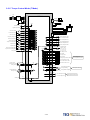
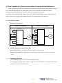
2-3-4 Speed Control Mode (S Mode)
NFB
R
R
Supply
Filter
S
T
S
T
SERVO
FG
45
Internal +24V DC
Digital input common
Servo ON ( SON)
CCW Limit ( CCWL)
CW Limit ( CWL)
Emergency stop ( EMC)
PI/P Switch ( PCNT)
Torque Limit ( TLMT)
Model Control ( MDC)
Alarm Clear ( ALRS)
Look ( LOK)
Speed 1 (SP1)
DICOM
DI-1
DI-4
1
4
DI-5
5
DI-9
9
DI-3
3
DI-6
6
DI-12
12
DI-2
2
DI-8
8
DI-10
10
Speed 2 (SP2)
Reverse Control ( SPDINV)
DI-13
13
IG24
48
Analog Ground
CW Torque Limit
Analog Speed Input (±10V)
Analog Ground
Shield ground
SERVO
MOTOR
V
11
CCW Torque Limit
U
47
DI-11
+24V ground
PC
Regeneration resistor
P
PC
P1
DC 24V
IP24
RS232
C
N
4
r
s
PIC
AG
NIC
SIN
AG
FG
FG
R1
Encoder
C
N
2
R1
R1
35
PA
R1
36
/PA
R1
37
PB
R1
38
/PB
R1
39
PZ
40
/PZ
R1
Encoder Output A Phase
Encoder Output /A Phase
Encoder Output B Phase
Encoder Output /B Phase
Encoder Output Z Phase
Encoder Output /Z Phase
R1
43
48
R1
DC24V
R1
20KΩ
27
29
28
26
29
W
R1
R2
Z0
R4
IG24
+Vc
External supply
*Max Vc=24V
Vc=24V, R4=4.7KΩ
Vc=12V, R4=2.4KΩ
Vc=5V, R4=1.0KΩ
45
18
DO-1
LOAD
Servo Ready (RDY)
19
DO-2
LOAD
Alam(ALM)
20
DO-3
LOAD
Zero Speed (ZS)
21
DO-4
LOAD
In Speed (INS)
22
DO-5
LOAD
Limiting Torque/Alarm Code 0
23
DO-6
LOAD
P in Action/Alarm Code 1
24
DO-7
LOAD
Servo in limit/ Alarm Code 2
25
49
DO-8
LOAD
Base Block /Alarm Code 3
Max Voltage: 24V
Max Output Current :10mA
IG24
20KΩ
R2
20KΩ
30
MON1
32
AG
31
MON2
R2
50
2-28
33
+15V
34
- 15V
Analog Monitor Output 1
Analog Grounding
Max Output Voltage 5mA
Analog Monitor Output 2
+15V PW output (AG)
Max Output Current 10mA
-15V PW output (AG)
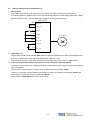
2-3-5 Torque Control Mode (T Mode)
NFB
R
R
Supply
Filter
S
T
SERVO
S
T
FG
45
P
PC
P1
47
U
DC24V
Internal+24 V DC
IP 24
Digital input common DICOM
RS232
C
N
4
r
s
PC
Regeneration resistor
SERVO
MOTOR
V
Servo ON ( SON)
CCW Limit( CCWL)
CW Limit ( CWL)
Emergency stop( EMC)
Model Control( MDC)
Alarm Clear( ALRS)
Torque Inverse(TRQINV)
Speed1 (SPD1)
Speed2 (SPD2)
Torque CW Selecting (RS1)
Torque CCW Selecting (RS2)
+24 V ground
Torque Control
Speed Limit (0~10V)
Analog Ground
Torque Input(±10V)
Analog Ground
Shield ground
DI-1
1
DI-4
4
DI-5
5
DI-9
9
DI-12
12
DI-2
2
DI-8
8
DI-10
10
DI-11
11
R1
35
PA
R1
36
/ PA
R1
37
PB
R1
38
/ PB
R1
39
PZ
R1
40
/ PZ
6
DI-7
7
R1
IG24
48
FG
43
48
DC24V
20KΩ
27
29
26
29
Encoder
C
N
2
R1
DI-6
SIN
AG
FG
R1
R1
PIC
AG
W
R1
R2
Z0
Encoder Output A Phase
Encoder Output /A Phase
Encoder Output B Phase
Encoder Output /B Phase
Encoder Output Z Phase
Encoder Output /Z Phase
R4
IG24
45
18
DO-1
19
DO-2
20
DO-3
21
DO-4
22
DO-5
23
DO-6
24
DO-7
25
49
DO-8
+ Vc External supply
*Max Vc=24V
Vc=24V , R4=4.7KΩ
Vc=12V , R4=2.4KΩ
Vc=5V , R4=1.0KΩ
LOAD
Servo Ready ( RDY)
LOAD
Alam( ALM)
LOAD
Zero Speed (ZS)
LOAD
In Speed ( INS)
LOAD
Limiting Torque /Alarm Code 0
LOAD
P in Action /Alarm Code 1
LOAD
Servo in limit /Alarm Code 2
LOAD
Base Block /Alarm Code 3
Max Voltage: 24V
Max Output Current:10mA
IG24
20KΩ
30
MON1
32
AG
31
MON 2
R2
50
2-29
33
+15V
34
- 15V
Analog Monitor Output 1
Analog Grounding
Max Output Current 5mA
Analog Monitor Output 2
+15V PW output (AG)
Max Output Current 10mA
-15V PW output (AG)
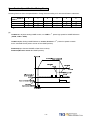
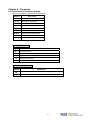
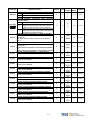
Chapter 3 Panel Operator / Digital Operator
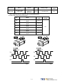
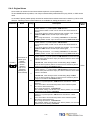
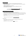
3-1 Panel Operator on the Drives
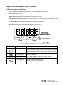
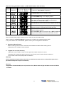
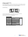
The operator keypad & display contains a 5 digit 7 segment display, 4 control keys
and two status LED displays.
Power status LED (Green) is lit when the power is applied to the unit.
Charge LED (Red) Indicate the capacitor ‘s charge status of main circuit. power on to light up Charge LED
and gradual dark when internal power capacitors are discharged complete.
Do NOT wire or assemble to the servo drive before Charge LED is off.
Key
Name
MODE/SET
INCREMENT
DECREMENT
DATA SETTING
&
DATA ENTER
Function Keys Description
1. To select a basic mode, such as the status display mode, utility
function mode, parameter setting mode, or monitor mode.
2. Returning back to parameter selection from data-setting screen.
1. Parameter Selection.
2. To increase the set value.
3. Press
and
at the same time to clear ALARM.
1. To confirm data and parameter item.
2. To shift to the next digit on the left.
3. To enter the data setting (press 2 sec.)
3-1
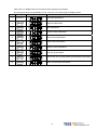
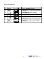
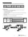
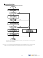
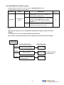
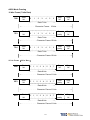
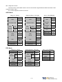
After power on, MODE button can be used to select 9 groups of parameter.
By pressing the Mode key repeatedly once at a time you can scroll trough the displays below.
Step
Key
1
Power on
Description
LED Display after Operation
Drive status parameters.
2
Diagnostic parameters.
3
Alarm parameters.
4
System Control parameters.
5
Torque Control parameters.
6
Speed Control parameters.
7
Position Control parameters.
8
Quick set up parameters.
9
Multi function I/O ( programmable Inputs/Outputs) Parameters.
10
Return to Drive status parameters.
3-2
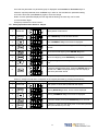
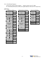
Once the first parameter in a parameter group is displayed use Increment or Decrement keys to
select the required parameter then use Enter key in order to view and alter the parameter setting,
once this is done then press Enter key again to save the change.
Notes: On each parameter display the first digit will be flashing, the enter key can be used
to move between digits.
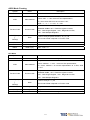
Example procedures are shown below: Ex: Setting Speed Parameter Sn203 to 100rpm.
Step
Key
1
Power On
Description
LED Display after Operation
Display status of servo drive
2
Press MODE-Key 6 times to select Sn 201
3
Press INCRMENT- Key twice Sn203 is displayed.
4
To view the Sn203 preset value by press ENTER-Key for 2
seconds
5
Shift to the second digit by press ENTER- Key once
6
Shift to next Digit by press ENTER-Key once again
7
Change the digit preset value by press the DECREMET-Key
twice
8
To save the altered preset value, Press the ENTER- Key for 2
seconds until “SET”is displayed briefly and then display is
returned to parameter Sn203
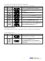
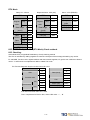
Following example shows the sequence where a parameter preset value is displayed
When no change is made and it is skip back to the original parameter by pressing the Mode-Key.
Step
Key
1
Power ON
Description
LED Display after Operation
When power on drive status parameter will display
2
Pressing MODE-Key 6 times, Sn 201 will be displayed.
3
Pressing INCRMENT- Key twice Sn203 is displayed.
4
To view the Sn203 preset press ENTER-Key for 2 seconds.
5
No change is made and LED display return to last select parameter
Sn203, press MODE-Key once skip
3-3
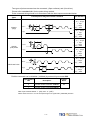
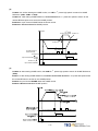
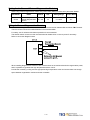
Some of the data entry in this drive are in the format shown below, for these data the Most significant digit
will be shown by the Capital letter “H” as shown below.
Ex: Home search function in position mode Pn365 = 0212. Each digit of this preset for Pn365 parameter
defines a selection for a specific function.
Bit0 corresponds to a selection for parameter Pn 365.0 and bit1 setting for Pn 365.1 … etc.
Parameter Pn 365 Format for the 5 digits data value is shown below:
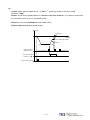
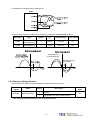
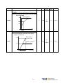
Display of Positive and Negative values:
Description of Positive/Negative Display
Display of Positive Display of Negative
For negative numbers with 4 digits or less, the negative sign is
displayed In the most significant digit as shown.
Ex: Sn201 (Internal Speed Command 1).
3000
-3000
For negative numbers with 5 digits the negative sign is indicated by
displaying all the 5 decimal points on the display.
Ex: Pn317(Internal Position Command 1- Rotation number)
30000
-30000
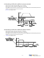
Setting a negative value.
(1) If the negative value has 4 digits or less follow the steps in the example below:
Ex: Sn201(Internal speed command 1)= preset speed of 100 to –100 rpm.
Step
Key
1
Power ON
Description
LED Display after Operation
On” power on “ Drive Status parameter is displayed.
2
Pressing MODE-Key 5 times, Sn 201 will be displayed.
3
To view the Sn201 preset press ENTER-Key for 2 seconds.
4
To move to the most significant digit press the ENTER-Key
4 times.
5
6
or
Use INCREMENT Or DECREMENT key until
the minus sign ( _ ) is displayed. You can toggle between – and
+ by this key.
To save the altered preset value, Press the ENTER- Key for 2
seconds until “SET”is displayed briefly and then
display is returned to parameter Sn201.
3-4
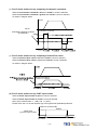
If the negative value has 5 digits follow the steps in the example below:
Ex: Pn317 (internal position preset command 1) set to a negative value -10000 revolutions.
Step
1
Description
Control Keys LED Display after Operation
Power On
On” power on “ Drive Status parameter is displayed.
2
Pressing MODE-Key 6 times, position parameter Pn 301 will
be displayed.
3
Use INCREMENT- Key to display Pn317.
4
To view the Pn317 preset press ENTER-Key for 2 seconds.
5
To move to the most significant digit press the ENTER-Key
4 times.
6
Press DECREMENT-Key once to set the most significant digit
To 1. And press the DECREMENT-Key once again.
All 5 decimal points will light up to indicate a negative number.
7
To save the altered preset value, Press the ENTER- Key for 2
seconds until “SET”is displayed briefly and then
display is returned to parameter Pn 317.
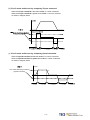
Alarm Reset from the Keypad.
All alarm displays can be cleared from the keypad without a need for an external Alarm clear (Reset) signal.
Ex. Under voltage Alarm AL-01.
Step
Control Key
1
Alarm
2
Description
LED Display after Opertion
Under voltage Alarm AL-01 is displayed.
To clear Alarm:Remove input contact SON (Servo On).
Then press INCREMENT-Key and DECREMENT-Key
at the same time.
The display will show RESET briefly and then returns back to
parameter display.
3-5
3-2 Signal Display
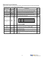
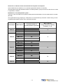
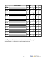
3-2-1 Status Display
Following parameters can be used to display drive and motor Status.
Parameter
Signal
Displayed
Unit
Description
Un-01
Actual motor speed
rpm
Un-02
Actual motor torque
%
It displays the torque as a percentage of the rated torue.
Ex: 20 are displayed. It means that the motor torque output is 20% of
rated torque.
Un-03
Regenerative load ratio
%
Value for the processable regenerative power as 100% .
Un-04
Accumulated load ratio
%
Value for the rated torque as 100%.
Un-05
Max load rate
%
Max value appeared on accumulated load rate
Un-06
Speed command
Un-07
Position error counter value
pulse
Un-08
Position feedback pulse counter
pulse The accumulated number of pulses from the motor encoder.
Un-09
External voltage command
V
External analog voltage command value in volts.
Un-10
Main circuit Vdc Bus Voltage
V
DC Bus voltage in Volts.
Un-11
External speed limit command
value
Un-12
External CCW Torque limit
command value
%
Ex: Display 100. Means current external CCW torque limit command is
set to 100 %.
Un-13
External CW Torque limit command
value
%
Ex: Display 100. Means current external CW toque limit command is set
to 100%.
Un-14
Motor feed back – Rotation value
(absolute value)
rev After power on, it displays motor rotation number as an absolute value.
Un-15
Motor feed back – Less then 1
After power on, it displays the pulse number for less than a revolution of
pulse
the motor as an absolute value.
rotation pulse value(absolute value)
Un-16
Pulse command – rotation
value(absolute value)
Un-17
Pulse command – Less then 1
After power on, it displays pulse command input for less than a rotation.
pulse
pulse value is an absolute value.
rotation pulse value(absolute value)
Un-18
Torque command
Un-19
Load inertia
Actual Motor Speed is displayed in rpm.
rpm Speed command is displayed in rpm.
Error between position command value and the actual position
feedback.
rpm Display external speed limit command value in rpm.
rev
After power on, it displays pulse command input rotation number in
absolute value.
It displays the torque command as a percentage of the rated torque.
Ex: Display. 50.Means current motor torque command is 50% of rated
torque.
When Cn002.2=0(Auto gain adjust disabled), it displays the current
preset load inertia ratio from parameter Cn025.
x0.1
When Cn002.2=1(Auto gain adjust enabled), it displays the current
estimated load inertia ratio.
%
3-6
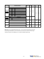
3-2-2 Diagnostic function
Following diagnostics parameters are available:
Parameter
Signal
dn-01
dn-02
dn-03
dn-04
dn-05
dn-06
dn-07
dn-08
dn-09
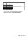
Name and Function
Control mode display
Output terminal status
Input terminal status
Software version (CPU version)
JOG mode operation
Reserve function
Auto offset adjustment of external analog command voltag
Servo model code
ASIC software version display
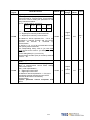
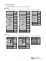
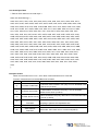
dn-01 (Control Mode Display)
Access dn-01 to display the selected control mode.
Control mode display description is listed in the table below:
Control Mode
dn-01 ( Control mode display)
Torque control-T
Speed control-S
Position control
(External pulse command)-Pe
Position/Speed control switch-Pe/S
Speed/Torque control switch-S/T
Position/Torque control switch-Pe/T
Position control
(Internal position command) -Pi
3-7
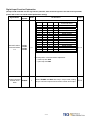
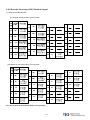
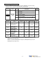
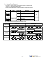
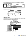
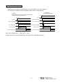
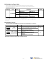
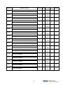
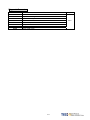
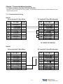
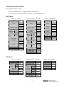
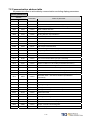
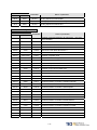
dn-02 (Output terminal status)
Use dn-02 to check the status of output terminals.
Output status display is described below:
When output terminal signal has a low logic level (close loop with IG24),
the corresponding LED will be on.
When output terminal signal has a high logic level (open loop with IG24),
the corresponding LED will be off.
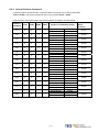
Table below shows the functions of the digital outputs.
DO-1~DO-4 are programmable outputs. Default settings are shown below.
DO-5~DO-8 are fix function outputs. ( non-programmable)
For programmable output list see section 5-6-1.
LED No.
1
2
3
4
5
6
7
8
Output terminal number
DO-1
DO-2
DO-3
DO-4
DO-5
DO-6
DO-7
DO-8
Default function
RDY
ALM
ZS
INP
LM/A0
PC/A1
ST/A2
BB/A3
Note: To set the logic state (High or Low) of for programmable digital outputs refer
to section 5-6-1.
For the DO-5~DO-8 ( non-programmable) terminals are active when logic is low.
3-8
dn-03 (Input terminals status)
Use dn-03 to check the status of Input terminals.
Digital Input status display is described below:
10
9
8
7
6
5
4
3
2
1
LED Number
When Input terminal signal has a low logic level (close loop with IG24), the corresponding LED will be on.
When Input terminal signal has a high logic level (open loop with IG24), the corresponding LED will be off.
Table below shows the functions of the digital input.
DI-1 ~ DI -10 are programmable Inputs. Default settings are shown below.
For programmable function list see section 5-6-1.
LED Number
1
2
3
4
5
6
7
8
9
10
Input terminal number
DI-1
DI -2
DI -3
DI -4
DI -5
DI -6
DI -7
DI -8
DI -9
DI -10
3-9
Default function
SON
ALRS
PCNT
CCWL
CWL
TLMT
CLR
LOK
EMC
SPD1
dn-04 (Version of Software)
Use dn-04 to view the current software version of the Servo drive.
Software version can be checked as below:
Step
Keys
1
Power On
Description
LED Display
On” power on Drive Status is displayed.
2
Press MODE-Key twice to view diagnostics parameter dn-01.
3
Press INCREMENT-Key 3 times to display dn-04.
4
Press ENTER-Key for 2 seconds to view the software version.
(Software version: 2.00)
5
Press MODE-Key once to return to dn-04 and parameter
selection.
3-10
dn-05 (JOG Operation)
Use dn-05 to JOG the motor. Jog is activated by following the steps below:
Note: JOG speed is in accordance with setting of Sn201(internal speed command 1).
Ensure that the required speed is set in Sn201 before executing this function.
Warning: Motor will be agitated run as soon as JOG command is activated.
without the need for SON input (Servo On signal).
Step
Key
1
Power on
LED display
Description
On” power on Drive Status is displayed.
2
Press MODE-Key once to view diagnostics parameter dn-01.
3
Press INCREMENT-Key 4 times to display dn-5.
4
Press ENTER-Key for 2 seconds to enter JOG MODE.
Motor will power on immediately.
5
Press INCREMENT-Key, motor will run in the pre-defined
positive direction.
6
7
Press DECREMENT-Key, motor will run in the pre-defined
negative direction.
Press MODE-Key once to return to dn-05 and parameter
selection.
Motor stoped the excitation immediately.
3-11
dn-07 (Auto offset adjustment of external analog command voltage)
If the external torque or speed analog command is set to 0V and the motor is rotating slowly,
this is due to analog input zero offset, use dn-07 to auto adjust this offset and stop the motor rotating.
Follow the steps below:
Step
1
2
Key
LED Display
Description
Insert a link between analog command terminal SIN(CN1-26) and Analog Ground terminal
AG(CN1-29) before proceeding.
Power on
On” power on “ Drive Status is displayed.
3
Press MODE-Key twice into diagnostics parameter dn-01.
4
Press INCREMENT-Key 6 times to display dn-7.
5
Press ENTER-Key for 2 seconds to enter dn-07
6
Press INCREMENT-Key once to set to 1
(Enable auto offset adjustment).
7
To save the altered preset value and activate auto offset adjust,
Press the ENTER- Key for 2 seconds until “SET”is displayed
briefly and then display is returned to parameter dn-07.
To save this offset value, please select parameters Tn104 or
Sn217 as required and press the ENTER-Key.
Tn107 for analog torque command.
Sn217 for analog speed command.
3-12
dn-08 (Servo motor Model Code display)
Use dn-08 to display servo motor code and check the servo drive and motor compatibility according to the table
below.
If the dn08 preset is not according to the list below then contact your supplier.
The motor model code is stored in parameter Cn30.
dn-08 Display
Cn030 Setting
H1111
H0112
H0121
H0122
H0130
H1133
H1134
H0140
H1141
H0142
H1143
H1144
H0211
H0212
H0220
H1221
H0222
H1223
H1224
H0230
H1233
H1234
H0241
H0242
H0251
H0252
Motor Standards
Drive Model
JSDA-15
JSDA-20
Motor Model
JSMA-SC01AB
JSMA-SC01AH
JSMA-LC03AB
JSMA-LC03AH
JSMA-SC02AF
JSMA-TC02AB
JSMA-TC02AH
JSMA-SC04AF
JSMA-SC04AB
JSMA-SC04AH
JSMA-TC04AB
JSMA-TC04AH
JSMA-LC08AB
JSMA-LC08AH
JSMA-SC04AF
JSMA-SC04AB
JSMA-SC04AH
JSMA-TC04AB
JSMA-TC04AH
JSMA-SC08AF
JSMA-TC08AB
JSMA-TC08AH
JSMA-MA05AB
JSMA-MA05AH
JSMA-MH05AB
JSMA-MH05AH
3-13
Watt
(W)
Speed
(rpm)
100
3000
300
3000
200
3000
400
3000
750
3000
400
3000
750
3000
1000
550
1500
Encoder
Specification
2500
8192
2500
8192
2000
2500
8192
2000
2500
8192
2500
8192
2500
8192
2000
2500
8192
2500
8192
2000
2500
8192
2500
8192
2500
8192
dn-08 Display
Cn030 Setting
H0310
H1313
H1314
H0321
H0322
H0331
H0332
H0341
H0342
H0351
H0352
H0361
H0362
H0371
H0372
H0381
H0382
H0511
H0512
H0521
H0522
H0531
H0532
H0541
H0542
H0551
H0552
H0711
H0712
H0721
H0722
Motor Standards
Drives Model
JSDA-30
JSDA-50
JSDA-75
Motor Model
JSMA-SC08AF
JSMA-TC08AB
JSMA-TC08AH
JSMA-MA10AB
JSMA-MA10AH
JSMA-MB10AB
JSMA-MB10AH
JSMA-MH10AB
JSMA-MH10AH
JSMA-MC10AB
JSMA-MC10AH
JSMA-MA15AB
JSMA-MA15AH
JSMA-MB15AB
JSMA-MB15AH
JSMA-MC15AB
JSMA-MC15AH
JSMA-MA15AB
JSMA-MA15AH
JSMA-MB15AB
JSMA-MB15AH
JSMA-MC15AB
JSMA-MC15AH
JSMA-MB20AB
JSMA-MB20AH
JSMA-MC20AB
JSMA-MC20AH
JSMA-MB30AB
JSMA-MB30AH
JSMA-MC30AB
JSMA-MC30AH
3-14
Watt
(W)
Speed
(rpm)
750
3000
1000
2000
1000
1500
3000
1000
1500
2000
3000
1000
1500
2000
3000
2000
2000
3000
2000
3000
3000
Encoder
Specification
2000
2500
8192
2500
8192
2500
8192
2500
8192
2500
8192
2500
8192
2500
8192
2500
8192
2500
8192
2500
8192
2500
8192
2500
8192
2500
8192
2500
8192
2500
8192
Chapter 4 Trial Operation
Before proceeding with trial run, please ensure that all the wiring is correct.
Trial run description below covers the operation from keypad and also from an external controller such as a PLC.
Trial run with external controller speed control loop (analog voltage command) and position control loop
(external pulse command).
(1) No-load servo motor. Trial run (Reference:4-1)
A. Servo Drive wiring and motor installation
B. Purpose of trial run
Confirm if the items below are correct:
.Drives power cable wiring
.Servo Motor wiring
.Encoder wiring
.Setting servo motor rotation direction and speed
(2) No-load servo motor with a host controller.
Trial run (Reference:4-2)
A. Servo drive wiring and motor installation
B. Purpose of trial run
Confirm if the items below are correct:
.Control signal wiring between host controller and servo
drive.
. Servo motor rotation direction, speed and rotating
number .
.Brake function, operation limit function and protection
function.
(3) Servo motor connected to load and controlled by a host controller. Trial run (Reference:4-3)
A. Servo drive wiring and motor installation
B. Purpose of trial run
Confirm if the items below are correct:
.Servo motor rotation direction, speed and
mechanical operation range.
.Set related control parameters.
4-1
4-1 Trial Operation Servo motor without Load
To carry out a successful trial run follow the steps below and ensure that drive wiring is correct and as specified.
Warning!
In order to prevent potential damage,prior to trial run ensure that the driven
mechanism, couplings and belts etc are disconnected from the motor.
1. Installation of servo motor.
Ensure that the motor is installed securely so that there is no movement and vibration during trial run.
2. Wiring.
Check servo drive 、motor power connections and motor encoder connection.
No control signal wiring is required of this stage thus remove connector (CN1) from the servo drive.
3. Servo drive power.
Apply power to servo drive. If the display shows any Alarm message such as graph below then refer to Alarm
contents of chapter 8 to identify the cause.
AL-14 is caused by Input terminals CCWL (Counter clockwise Limit) and CWL (Clockwise Limit)
being activated at the same time.
See (the default setting of high or low input logic state according to the description in section 5-6-1 ).
Because of the alarm, the servo can not operate normally.
Set the parameter Cn002.1=1 to disable the drive limit function temporarily during trial run period.
4-2
Steps for setting parameter Cn002.1 ( CCWL &CWL Rotation limit selection).
Setp
Keys
1
Power on
LED Display
Description
On” power on “ Drive Status is displayed.
2
Press MODE-Key 4 times to display Cn001.
3
Press INCREMENT-Key once to display Cn002.
4
Press ENTER-Key for 2 secs to display the preset value of
Cn002. Note: Cn 002 includes 4 digits corresponding to
Cn002.0,Cn002.1,Cn002.2 & Cn002.3.
5
Press ENTER-Key once to move to the 2nd digit for (Cn 002.1).
6
Press INCREMENT- Key once to adjust the 2nd digit to 1.
Disable the function of external limits CCWL and CWL.
7
To save the setting value by
Press the ENTER- Key for 2 seconds until “SET”is displayed
briefly and then display is returned to parameter Cn-002.
After accomplish these steps, reset the power. If there are any other alarms then
refer to section 8-2 (Clearing Alarms). Once there is no alarms then operate the drive again.
If any of the alarms can not be cleared, please contact your local supplier for assistance.
4. Mechanical Brake Release.
When a brake type servo motor is used then must release the brake before starting trial run
by applying 24vdc voltage to brake terminals.
5.
Keypad Trial run (JOG function).
Jog function can be used to check if motor speed and rotation direction is correct.
Parameters Sn 201(internal speed command 1) and Cn004 (motor rotation direction selection)
Can be used to set the required speed and direction.
Warning!
Set the required JOG speed before the trial run otherwise the motor will run at the default speed set in
parameter Sn201(internal speed command 1).
Warning!
Regardless of external SON (servo on) is active of not, Servo motor will get excitation as soon as JOG is
activated.
4-3
Steps for setting JOG function:
Step
Keys
1
Power on
LED Display
Description
On” power on “ Drive Status is displayed.
2
Press MODE-Key twice to view diagnostics parameter dn-01.
3
Press INCREMENT-Key 4 times to display dn-5.
4
Press ENTER-Key for 2 seconds to enter JOG MODE.
Motor will power on immediately.
5
Press INCREMENT-Key, motor will run in the pre-defined
positive direction.
6
Press DECREMENT-Key, motor will run in the pre-defined
negative direction.
7
Press MODE-Key once to return to dn-05 and parameter
selection.
Motor power will be turned off immediately.
4-4
4-2 Trial Operation for Servo motor without Load from Host Reference
Check and ensure that all power connections to the drive and motor and control signal connection between
the host controller and the drive are correct.Motor must be mechanically disconnected from the load.
Following section describes the trial run when using a host controller such as a PLC.
Two trial runs have been discussed. Speed control mode ( Section B) and Position control mode ( Section C).
Section A shows the connections and SON signal (servo on) requirements for both trial runs.
A. Launching Servo motor
Example wiring diagram:
Speed Control(Cn001=1)
Position Control(Cn001=2)
Servo Drives
Servo Drives
IP24
DICOM
SON
CN1-45
DICOM
CN1-47
SON
CN1-1
CCWL CN1-4
CWL CN1-5
IG24
SIN
IP24
CN1-48
CN1-47
CN1-1
Servo Motor
CCWL CN1-4
Servo Motor
CWL CN1-5
M
IG24
Pulse
/ Pulse
CN1-26
Sign
AG
CN1-45
CN1-32
/ Sign
M
CN1-48
CN1-14
CN1-15
CN1-16
CN1-17
a. Disable Analog Input command terminals.
Speed control mode: Link analog input terminal SIN to 0V terminal (AG).
Position control mode: Link external pulse command terminals “Pulse” to ”/Pulse” and “Sign” to
“/Sign”.
b. Enable Servo ON Signal
Connect SON terminal to IG 24 (0V) terminal (Digital Ground).
On drive power up servo will be turned on. Now check for any Alarms. If any alarms then refer to
Chapter 8-2 for how to reset the Alarms.
4-5
B.
Trial run in Speed control mode(Cn001=1).
1. Wiring check:
Check and ensure that all power cable and control signal connections are correct as shown below.
To be able to adjust the speed for test connect a potentiometer between terminals SIN (analog input voltage)
and AG (Analog Ground). Set the analog input voltage to 0V. (No speed reference).
Servo Drive
IP24
DICOM
SON
CN1-45
CN1-47
CN1-1
CCWL CN1-4
Servo Motor
CWL CN1-5
IG24
SIN
AG
2.
CN1-48
CN1-26
CN1-32
Apply Servo on.
Apply power to the drive and activate (SON) signal by switching SON terminal to IG24 (input digital Ground).
If the motor rotates slowly, while the speed analog input voltage is 0 volts
then use dn-07 function to auto offset adjustment for the analog input value. (refer to section 3-2-2).
3. Check the relationship between motor speed and the analog input speed command.
Increase the analog speed input voltage gradually (by potentiometer) and monitor the actual motor speed by
parameter Un0-01.
Check if motor rotation direction is correct and if necessary set it by parameter Cn004.
Check for correctness of analog speed command ratio in relation to the preset in parameter (Sn216) and
analog speed command limit as set in parameter (Sn218).
Finally, switch off SON signal (turn off the servo motor).
4-6
4. Connection with a host controller.
Check and ensure that the wiring for the servo drive and host controller, speed analog signal input (SIN), and
encoder output (PA, /PA, PB, /PB, PZ, /PZ) are all correct and according to the diagram below:
5. Confirm the rotation number and encoder output of Servo Motor.
Use parameter Un-14 to check if the Motor feed back (number of revolutions) per minute is correct and the
same as number of revolutions sent by the host controller.
If there is any difference then check and make sure that parameter Cn005 ( Encoder ppr) is set correctly.
Once this is complete remove SON signal to switch off power to the motor.
4-7
C.
Position control mode trial run (Cn001=2).
1. Wiring:
Check and ensure that all power connections to the drive and motor and control signal connections are correct as
diagram below.
2. Setting electronic gear ratio.
Set electronic gear ratio parameters Pn302~Pn306 as required for the positioning application.
(refer to section 5-4-3).
Note: Electronic gear ratio parameter can be used to scale the command output pulse.
This would be useful in transmission applications where move distance per move command pulse
has to be scaled due to mechanical requirements.
3. Apply Servo on.
Apply power to the drive and activate (SON) signal by switching SON terminal to IG24 (input digital Ground).
4. Confirm motor speed, direction and number of revolutions.
Apply a low-speed pulse command from the host controller to the servo drive so that the servo motor
operates at low-speed.
•
Compare the number of pulses per revolution from parameters Un-15 ( motor feed back pulse ppr)
and Un-17 (Input command ppr) these should be the same.
•
Compare the number of revolutions using parameters Un-14 ( motor feed back rotation number) and
Un-16 (pulse command rotation number) these should be the same.
If there are differences then adjust electronic gear ratio parameters Pn302~Pn306 as required and test
again until the result is satisfactory.
If the direction of motor rotation is incorrect then check and if necessary set parameter Pn 301.0
(position pulse command types).
Also check and if necessary set parameter Pn314 (Position command direction selection).
Once the test result is correct then remove SON signal. (Power to the motor is switched off).
4-8
4-3 Trial Operation with the Servo motor Connected to the Machine
Servo drive parameters must be set correctly otherwise damage to machinery and potential injury
may result.
Do not close to the machine after temporary power loss, the machine may restart unexpected.
Please take the measures highlighted in the section below before trial run with load.
•
Consider the Mechanical system requirements and set the parameters appropriate for control by the host
controller.
•
Ensure that the rotation direction and speed are suitable for the Mechanical system.
Steps required for Trial run.
1. Ensure that the ServoDrive Power is off.
2. Connect the servo motor to the load shaft.
Refer to Chapter 1-5 to check the installation guidelines for the servo motor.
3. Gain adjustment for the servo control loop.
Refer to Chapter 5-5 for details.
4. Trial run with a host controller.
Run command is to be signaled by the host controller.
Refer to Chapter 4-2 to choose the required trial run mode (Speed control or position control modes)
according to the application and set and adjust the parameters if necessary for the application.
5. Repeat adjusting and record the set parameter values.
Repeat steps 3 and 4 until the mechanical system is operating satisfactorily then
record the Gain value and the parameters changes for the future use.
4-9
Chapter 5 Control Functions
5-1 Control Mode Selection
There are three control modes in the servo drive, torque, speed and position modes can be selected
individually or as a combination according to the selection table below:
Parameter
Name
0
1
2
★ Cn001
Control mode
selection
Description
Default
Value
Control
Mode
Torque control
To use one analog voltage command signal to control
torque. Please refer to 5-2.
Speed control
Input contacts SPD1 and SPD2 can be used to select 4
-steps of speed. Please refer to section 5-3-1.
Position control (External pulse command)
Four separate selectable pulse command types are
possible to control position. Please refer to section
5-4-1.
Position / Speed control switch
Input contact MDC can be used to switch between
position & speed control. Please refer to section 5-6-2.
Speed / Torque control switch
Input contact MDC can be used to switch between speed
& torque control. Please refer to section 5-6-2.
Position / Torque control switch
Input contact MDC can be used to switch between
position & torque control. Please refer to section 5-6-2.
Position control (internal position command)
Input contacts POS 1~POS 4 can be used to select 16
programmable preset position commands to control
position. Please refer to 5-4-2.
2
ALL
Setting
3
4
5
6
New setting will become effective after re-cycling the power.
5-1
5-2 Torque mode
Torque mode is used in applications such as printing machines, coil wiring machines, injection molding
machines and specific application that requiring torque control.
Diagram below shows the torque control process diagram.
Analog voltage torque command is applied to the drive input terminals as shown below:
Caution!
Care should be taken in selection of required torque direction CW/CCW.
Please refer to Chapter 5-2-4.
5-2
5-2-1 Analog Torque command Ratio.
Analog torque command ratio can be used to adjust the relationship between
Input voltage torque command and actual torque command.
Parameter
Name
Default
Unit
Setting range
Control Mode
Tn103
Analog torque
command ratio
300
%/10V
0~300
T
Setting example: refer to the following diagram.
1. With Tn103 set to 300, a torque command input voltage of 10V, corresponds to
300% of rated torque. For input voltage of 5V, actual torque command will be 150% of rated torque.
2. With Tn03 set to 200 , a torque command input voltage of 10V, corresponds to
200% of rated torque. For input voltage of 5V, actual torque command will be 100%.
300
Torque
200
Command (%)
100
-10
-5
-100
10
5
Input Voltage (V)
-200
-300
5-3
Slope is set by Tn103
5-2-2 Adjusting the analog torque command offset
For a torque command of 0V, motor could possibly be rotating slowly.
To rectify this effect by adjust offset value in parameter Tn104 or use auto offset adjust feature.
(Please refer to section 3-2-2).
Note : To check and set the offset to zero, insert a link between analog torque command contact
SIN(CN1-26) and analog ground contact AG (CN1-29).
Parameter
Name
Default
Unit
Setting range
Control mode
Tn104
Analog torque
command offset
0
mV
-10000~10000
T
Input Voltage (V)
Bias Voltage
Torque Command (%)
5-4
5-2-3 Torque command linear acceleration and deceleration
An smooth torque command can be achieved by enabling acceleration/Deceleration parameter Tn101.
Parameter
Name
Setting
★ Tn101
Linear acceleration/
deceleration method
Description
0
Disable
1
Enable
Control
mode
T
Torque command acceleration/deceleration time,
is the time taken for the torque to rise from zero to the required level by Tn102.
As per diagram below:Parameter
Name
Default
Unit
Setting Range
Control
mode
★ Tn102
Linear acceleration
/deceleration time period
1
msec
1~50000
T
New setting will become effective after re-cycling the power.
Torque Command
Rated Torque
Command
Required Torque
Command
Tn102
Setting examples:
(1) To achieve 50% of rated torque output in 10msec:
Tn102 = 10(msec) ×
100%
= 20(msec)
50%
(2) To achieve 75% of rated torque output in 10msec:
Tn102 = 10(msec) ×
100%
= 13(msec)
75%
5-5
Time (ms)
5-2-4 Definition of torque direction
In torque mode, torque direction can be defined by one of the following three methods.
(1) Input contacts RS1, RS2. (torque command CW/CCW selectable by programmable input)
(2) Parameter Cn004. (motor rotation direction )
(3) Input contact TRQINV. (reverse torque command)
Caution !
All 3 methods can be active at the same time.
User must ensure that correct selections are made for these three selections.
Control
mode
Input Contact
Description
RS2
RS1
0
0
Zero torque
Rotation in the current torque command
0
1
direction
Reverse the current torque command direction
1
0
1
1
Zero torque
T
Note: RS2 and RS1 contact status “1” (ON) and “0” (OFF).
Please check 5-6-1 to set the required high /Low signal levels ( PNP/NPN) .
Parameter
Signal
Name
Motor rotation
direction (load end)
Control
mode
Description
Setting
No.
Torque Control
Speed Control
0
Counter Clockwise(CCW)
Counter Clockwise (CCW)
1
Clockwise(CW)
Counter Clockwise (CCW)
CCW
S/T
Cn004
CW
2
Counter Clockwise (CCW)
Clockwise (CW)
3
Clockwise (CW)
Clockwise (CW)
Input contact TRQINV
Description
0
Rotation in current torque command
direction
1
Reverse torque command direction
Control
mode
T
Note: Input contacts status “1” (ON) and “0” (OFF).
Please refer to 5-6-1 to set the required high /Low signal levels ( PNP/NPN) selection.
5-6
5-2-5 Internal Torque Limit
In torque Control mode, user can set internal torque limit values as required.
Set as below:Parameter
Name
Default
Unit
Setting range
Control mode
300
%
0~300
ALL
-300
%
-300~0
ALL
CCW Torque
command limit
CW Torque
command limit
Cn010
Cn011
5-2-6 Limiting Servomotor Speed during Torque Control
In torque control, input contacts SPD1 and SPD2 can be used for selecting one of the two
methods below for setting speed limits.
(1) External Analog command ( Default) Signal is applied to terminals PIC & AG ( pins 27& 29 on CN1)
(2) Selection of Three presentable Limits (Tn105~Tn107) according to the table below.
Caution! For achieving smooth speed response please refer to section 5-3-6.
Input contact SPD2
Input contact
SPD1
0
0
0
1
1
0
1
1
Speed limit command
Control
mode
External analog
command
PIC(CN1-27)
Internal speed limit1
Tn105
Internal speed limit2
Tn106
Internal speed limit3
Tn107
T
Note: Input contacts status “1” (ON) and “0” (OFF).
Please check 5-6-1 to set the required high /Low signal levels ( PNP/NPN) selection.
Below is the external analog speed limit command wiring diagram:
Internal presentable speed limit parameters for torque control mode are listed below:
These preset limits apply to both CW & CCW directions.
Parameter
Name
Default
Unit
Setting range
Control mode
Tn105
Tn106
Tn107
Internal speed limit 1
Internal speed limit 2
Internal speed limit 3
100
200
300
rpm
rpm
rpm
0~3000
0~3000
0~3000
T
T
T
P.S also refer to page 6-11 for detail.
5-7
5-2-7 Additional torque control functions
Torque Output Monitor
When the torque level in CW or CCW directions becomes greater than the value set in
Tn108 (torque level monitor value), the output contact INT is active.
Parameter
Name
Default
Unit
Setting range
Control mode
Tn108
Torque output monitor
level
100
%
0~300
ALL
Note: Input contacts status “1” (ON) and “0” (OFF).
Please check 5-6-1 to set the required high /Low signal levels (PNP/NPN) selection.
Torque Smoothing Filter
Torque vibration can be diminution by setting an appropriate value in Cn034 (Torque command smoothing
filter), In the other hand, this will cause a delay in the response time of the torque loop.
Parameter
Cn034
Name
Torque smoothing
filter
Default
Unit
Setting range
Control mode
0
Hz
0~1000
ALL
5-8
5-3 Speed Mode
Speed Mode is necessary for applications that require precisely speed control, such as weaving, drilling
and CNC type machines.Diagrams below shows the speed control system in two parts.
First stage shows Speed processing and conditioning and the second stage shows the Speed controller
With PI/P control modes, and controller1&2 selection and interface with torque control stage.
Speed Command Processor
Analog Speed Command
Host Controllor
A/D
Once Smooth
AC/deceleration
Analog Speed Command Limit
Ratio
Sn216
Sn206
Sn218
Sn217
Linear
AC/deceleration
Bias Adjusting
Speed
Rotating Direction
Cn004
Input Contact
SPDINV
Speed Feed Back
Sn208~Sn210
Cn005
Sn201~Sn203
Encoder Signal
Encode-ratio Output
Internal Speed Command
Speed Controller
S-Curve
AC/deceleration
Sn205
AC/deceleration Method
Speed Controller
Analog Torque Limit
A/D
Speed Controller 1
Resonance filter
Speed Command
From Speed
Processor
Analog Torque Limit
Sn211, Sn212
Torque Control
Loop
Cn013, Cn014
Internal Torque
Limit
Speed Controller 2
Speed
Feed Back
Smooth Filter
Cn032
Sn213, Sn214
Gain switch method
Cn010, Cn011
Input Contact
Cn015~Cn024
Speed Feed Back
5-9
5-3-1 Selection for speed command
In Speed control, input contacts SPD1 and SPD2 can be used for selecting one of the two methods below
for setting speed limits.
(1) External Analog command (Default) : Analog signal is input from terminals SIN & AG (pins 26& 29 on
CN1)
(2) Internal speed command: Selection of Three presentable Limits according to the table below.
.
Input Contact SPD2 Input Contact SPD1
Speed Command
0
0
External analog command
SIN(CN1-26)
0
1
Internal speed command 1
Sn201
1
0
Internal speed command 2
Sn202
1
1
Internal speed command 3
Sn203
Control
Mode
S
Note: Input contacts status “1” (ON) and “0” (OFF).
Please check 5-6-1 to set the required high /Low signal levels (PNP/NPN) selection.
Diagram below shows the external analog speed command wiring:
Internal presetable speed limit parameters for speed command mode are listed below:
These preset limits apply to both CW & CCW directions.
Parameter
Sn201
Sn202
Sn203
Name
Internal speed
command 1
Internal speed
command 2
Internal speed
command 3
Default
Unit
Setting range
Control mode
rpm
-3000~3000
S
100
200
300
5-10
5-3-2 Analog speed command Ratio
Analog speed command ratio can be used to adjust the relationship between
Input voltage speed command and actual speed command.
Parameter
Name
Default
Unit
Setting range
Control mode
Sn216
Analog speed
command ratio
3000
rpm/10V
100~4500
S
Setting Example:
(1) With Sn216 set to 3000, a speed command input voltage of 10V, corresponds to
3000rpm; for an input voltage of 5V speed command will be 1500rpm.
(2) With Sn216 set to 2000, a speed command input voltage of 10V, corresponds to 2000rpm,
for an input voltage of 5 volts speed command will be 1000rpm.
5-3-3 Adjusting the analog reference offset
For a speed command of 0V, motor could possibly be rotating slowly.
To rectify this effect by adjust offset value manually in parameter Sn217 or use auto offset adjust feature.
(Please refer to section 3-2-2).
Note : To check and set the offset to zero, insert a link between analog torque command contact
SIN(CN1-26) and analog ground contact AG (CN1-29).
Parameter
Sn217
Name
Analog speed
command offset
adjust
Default
Unit
Setting range
Control mode
0
mV
-10000~10000
S
5-11
Refer to the following diagrams:
Input Voltage (V)
Input Voltage (V)
Bias Voltage
Bias Voltage
Adjusting Value
Speed Command(rpm)
Speed Command(rpm)
5-3-4 Analog reference for speed command limit
A maximum limit for analog speed can be set by Sn218.
Parameter
Name
Default
Unit
Setting range
Control mode
Sn218
Analog speed
command limit
Rate rpm
x 1.02
rpm
100~4500
S
5-3-5 Encoder Signal Output
Servo motor encoder pulse signal can be output to a host controller to establish an external control loop.
Set the required encoder Pulse Per Revolution (PPR) in parameter Cn005.
Default output value is the actual encoder PPR.
5-12
Parameter
Name
Default
Unit
Setting range
Control
mode
★Cn005
Encoder pulse
output scale
Encoder
Pulse Per
Revolution
pulse
1~ Encoder PPR
ALL
New setting will become effective after re-cycling the power.
Encoder pulse output terminal description:
Pin
PA
/PA
PB
/PB
PZ
/PZ
Pin NO. of
CN1
Name
Encoder pulse output A Phase
signal
Encoder pulse output /A Phase
signal
Encoder pulse output B Phase
signal
Encoder pulse output /B Phase
signal
Encoder pulse output Z Phase
signal
Encoder pulse output /Z Phase
signal
90
Control
mode
CN1-35
CN1-36
CN1-37
ALL
CN1-38
CN1-39
CN1-40
90
PA
PA
PB
PB
PZ
PZ
TIME
TIME
5-13
5-3-6 Smoothing the speed command
Sn205 can be used to eliminate speed overshoot and motor vibration by selecting one of the
acceleration /deceleration methods which is suitable for the application from the table below.
Parameter
Name
Sn205
Speed
command
accel/decel
smooth
method
Setting
Control
mode
Description
0
Disable accel/decel smooth function
1
Smooth accel/decel according to parameter Sn206
2
Linear accel/decel according to parameter Sn207
3
S-curve accel /decel according to parameter Sn208
S
Above three methods of Acceleration/deceleration are described below.
(1)Speed command smooth ac/deceleration:
Set Sn205=1 to enable the use of speed command smooth acceleration/deceleration function.
Parameter
Name
Default
Unit
Setting range
Control
mode
Sn206
Speed command smooth
accel/decel time Constant
1
msec
1~10000
S
Smooth acceleration/deceleration time corresponds to the time in which the speed command increases from 0 to
63.2% as shown in diagram below.
5-14
Setting example:
(1) To achieve 95% of speed command output in 30msec:
Set
Sn206 =
30(msec)
= 10(msec)
- ln(1- 95%)
(2) To achieve 75% of speed command output in 30msec:
Set Sn206 =
30(msec)
= 22(msec)
- ln(1 - 75%)
ln= Natural log
(2)Speed command linear acceleration/deceleration function:
Set Sn205=2 to enable the use of speed command linear acceleration/deceleration function.
Parameter
Name
Default
Unit
Setting range
Control
mode
Sn207
Speed command linear
accel/decel time constant
1
msec
1~50000
S
Linear acceleration/deceleration time corresponds to the time in which the speed increases (linearly)
from zero to the rated speed. As shown in the diagram below.
Speed Command
Rated Speed Command
Current Speed Command
Sn207
Setting examples:
(1) To achieve 50% of rated speed output in 10msec:
Set Sn207 = 10(msec) ×
100%
= 20(msec)
50%
(2) To achieve 75% of rated speed output in 10msec:
Set Sn207 = 10(msec) ×
100%
= 13(msec)
75%
5-15
Time(ms)
S-Curve Speed Command Acceleration/Deceleration:
Set Sn205=3 to enable the use of S-Curve speed command ac/deceleration function.
Parameter
Sn208
Sn209
Sn210
Name
S-Curve speed command
accel/decel time setting
S-Curve speed command
acceleration time setting
S-Curve speed command
deceleration time setting
Default
Unit
Setting range
Control mode
1
msec
1~1000
S
200
msec
0~10000
S
200
msec
0~10000
S
In applications where normal acceleration/deceleration on ramp up or ramp down bring in vibration of the
mechanical
system. S- curve acceleration/deceleration parameters could help to reduce vibration as diagram below:
Speed Command (rpm)
ts=Sn208
ta=Sn209
td=Sn210
ts
ts
ts
ta
Caution! Setting Rule:
ts
td
ta
t
> ts , d > ts
2
2
5-16
Time (ms)
5-3-7 Setting rotation direction
Motor rotation direction in speed mode can be set by parameter Cn004 (Motor rotation direction)and input
contact SPDINV according to the tables below.
Caution!
Both methods can be operated at the same time.
Ensure that these parameters are set correctly for the required direction.
Parameter
Name
Motor rotation
direction (observation
from load side).
No.
0
Control
mode
Description
Setting
Torque control
Speed control
Counter Colckwise (CCW) Counter Colckwise (CCW)
CCW
1
Colckwise (CW)
Counter Colckwise (CCW)
Cn004
S/T
CW
Input contact
SPDINV
2
Counter Colckwise (CCW)
Colckwise (CW)
3
Colckwise (CW)
Colckwise (CW)
Description
0
Rotation by speed command direction.
1
Rotation by reverse speed command direction.
Control
mode
S
Note: Input contacts status “1” (ON) and “0” (OFF).
Please check 5-6-1 to set the required high /Low signal levels (PNP/NPN) selection.
5-17
5-3-8 Speed Loop Gain
In speed mode there are two speed controller loops,
with separate Gain ( P) and Integral (I) functions.
Speed controllers 1 or 2 can be selected by setting one of the multi- function input terminals,
to selection G-SEL or by setting one of the parameters Cn20-Cn24 as required.
Please refer to section 5-3-11 section B for more details.
Parameter
Name
Default
Unit
Setting range
Control
mode
Sn211
Speed loop gain 1
40
Hz
10~450
Pe/Pi/S
Sn212
Speed loop integral time constant 1
100
x0.2
ms
1~500
Pe/Pi/S
Sn213
Speed loop gain 2
40
Hz
10~450
Pe/Pi/S
Sn214
Speed loop integral time constant 2
100
x0.2
ms
1~500
Pe/Pi/S
Diagram below shows the speed controller.
Setting a high speed loop gain or a lower speed loop integral time provides a faster speed control response
time.
For more details refer to section 5-5.
Kv 1
1
TiS
5-18
Kv: Speed Loop Gain (Hz)
Ti: Speed Loop Integral
Time Constant (sec)
5-3-9 Notch Filter
The function of the Notch filter is to suppress mechanical system resonance.
Resonance occurs due to low mechanical system rigidity (high springiness) of transmission systems used
with servo motors such as couplings, bearings, lead screws, etc.
Enter the mechanical system vibration (resonance frequency) in parameter Cn013 (Notch Filter frequency)
and adjust Cn014 to set the filter bandwidth scaling factor.
Lower the setting of Cn014 value, wider is the notch filter frequency bandwidth. The adjustment required
depends on the application.
Caution!
If Cn013 is set to “0” the Notch filter is disabled.
Parameter
Name
Defaul
t
Unit
Setting range
Control mode
Cn013
Notch Filter frequency
0
Hz
0~1000
Pi/Pe/S
Cn014
Notch Filter Band Width
Scaling factor
7
X
1~100
Pi/Pe/S
5-19
5-20
Q3
Q1
Cn013
(Notch Filter-Frequency
Q2
Response Line for Notch Filter
Resonant Frequency
The Response Line for Resonance
Q1>Q2>Q3
Cn014(Notch Filter-Quality Factor)
Gain
Gain
Frequency
Frequency
Gain
After adding Notch Filter
Frequency
5-3-10 Torque limit of speed control mode
In speed mode, the motor torque limit input contact TLMT could be used to select one of the two methods
below:
(1) Internal toque limit: Using default Cn010 (CCW Torque command limit ) and
Cn011(CW Torque command limit ).
(2) External analog command: Using two separate analog voltage command signals at input terminals
PIC(CN1-27) to limit CCW torque and NIC(CN1-28) to limit CW torque.
As shown in the table below:
Input contact
TLMT
CCW torque command limit
source
CW torque command limit
source
Control
mode
0
Cn010
Cn011
ALL
1
External analog command
PIC(CN1-27)
External analog command
NIC(CN1-28)
Pi/Pe/S
Note: Input contacts status “1” (ON) and “0” (OFF).
Please check 5-6-1 to set the required high /Low signal levels ( PNP/NPN) selection.
Caution!
To use external analog torque command limit , If analog torque command limit is greater than
internal torque command limit, the internal torque command limit has the priority over external
analog torque command limit.
Internal Torque command limit is set as below.
Parameter
Cn010
Cn011
Name
Default
Unit
Setting range
300
-300
%
%
0~300
-300~0
CCW torque command limit
CW torque command limit
The diagram below shows the external analog torque limit command wiring:
5-21
Control
mode
ALL
ALL
5-3-11 Gain Switched
PI/P control mode selection (Section A)
Automatic gain 1& 2 switch (Section B)
The selection of PI/P control mode switch and Automatic gain 1& 2 switch by parameters or from input
terminals can be used in following conditions.
(1) In speed control, to restrain acceleration/deceleration overshooting.
(2) In position control, to restrain oscillations and decrease the adjusting time.
(3) To decrease the possible noise caused by using Servo Lock function.
(A) Switching between PI/P Control modes
Switch over from PI to P mode is determined by setting of parameter Cn015.0 and according to
the selection options below:
Parameter
Signal
Name
0
1
Cn015.0
PI/P control
mode
switch
2
3
4
Parameter
Cn016
Cn017
Cn018
Cn019
Description
Control
mode
Switch from PI to P if the torque command is
greater than Cn016
Switch from PI to P if the speed command is
greater than Cn017
Switch from PI to P if the acceleration command is
greater than Cn018
Switch from PI to P if the position error is greater
than Cn019
Switch from PI to P by the input contact PCNT.
Set one of the multi function terminals to option 03.
Pi/Pe/S
Setting
Name
PI/P control mode switch by
(torque command)
PI/P control mode switch by
(speed command)
PI/P control mode switch by
(acceleration)
PI/P control mode switch by
(position error value)
Default
Unit
Setting range
Control
mode
200
%
0~399
Pi/Pe/S
0
rpm
0~4500
Pi/Pe/S
0
rps/s
0~18750
Pi/Pe/S
0
pulse
0~50000
Pi/Pe/S
5-22
(1) PI to P mode switch over by comparing Torque command.
When the Torque command is less than Cn016 PI control is selected.
When the Torque command is greater than Cn016 P control is selected..
As shown in diagram below:
(2) PI to P mode switch over by comparing Speed command.
When the Speed command is less than Cn017 PI control is selected.
When the Speed command is greater than Cn017 P control is selected.
As shown in diagram below:
Speed
PI/P -Mode Switching Condition
(Speed Command)
5-23
(3) PI to P mode switch over by comparing Acceleration command.
When the Acceleration command is less than Cn018 PI control is selected.
When the Acceleration command is greater than Cn018 P control is selected.
As shown in diagram below:
Speed
Cn018
PI/P-Mode Switching Condition
(Acceleration)
Acceleration Command
(4) PI to P mode switch over by comparing Position Error value.
When the Position Error value is less than Cn019 PI control is selected.
When the Position Error value is greater than Cn019 P control is selected.
As shown in diagram below:
(5) PI to P mode switch over by PCNT input contact.
When the PCNT input contact is open PI control is selected.
When the PCNT input contact is closed P control is selected.
Note: Input contacts status “1” (ON) and “0” (OFF).
Please check 5-6-1 to set the required high /Low signal levels (PNP/NPN) selection.
Switch PI/P
by PCNT input contact
1
Status of contact PCNT
Enable
0
P control
PI control
5-24
PI control
(B) Automatic gain 1& 2 switching
Selection of Automatic gain 1& 2 switch with different P&I Gains is possible by setting
Parameter Cn 015.1 to one of the selections listed in the table below.
Parameter Cn 020 can be use for setting a switch delay time between different gains. (Gain 1 and 2)
Parameter
Name
Setting
0
1
Cn015.1
Automatic
gain 1& 2
switch
2
3
4
Parameter
Cn020
Cn021
Cn022
Cn023
Cn024
Control
Mode
Description
Switch from gain 1 to 2 if torque command is greater
than Cn021.
Switch from gain 1 to 2 if speed command is greater
than Cn022.
Switch from gain 1 to 2 if acceleration command is
Pi/Pe/S
greater than Cn023.
Switch from gain 1to2 if position error value is
greater than Cn024.
Switch from gain 1 to 2 by input contact G-SEL. Set
one of the multi function terminals to option 15 of
Hn501.
Name
Automatic gain 1& 2
switch delay time.
Automatic gain 1& 2
switch condition
(torque command)
Automatic gain 1& 2
switch condition
(speed command)
Automatic gain 1& 2
switch condition
(acceleration
command)
Automatic gain 1& 2
switch condition
(position error value)
Default
Unit
Setting Range
Control
Mode
0
x0.2 msec
0~10000
Pi/Pe/S
200
%
0~399
Pi/Pe/S
0
rpm
0~4500
Pi/Pe/S
0
rps/s
0~18750
Pi/Pe/S
0
pulse
0~50000
Pi/Pe/S
Note: Gain 1 : is consisted of Pn310(position loop gain 1), Sn211(speed loop gain 1 ) and
Sn212(Speed loop integral time 1).
Gain 2 : is consisted of Pn311(position loop gain 2), Sn213(speed loop gain 2) and
Sn214(Speed loop integral time 2 ).
5-25
(1) Automatic gain 1&2 switch condition ( by torque command ).
When torque command is less than Cn021 , Gain 1 is selected.
When torque command is greater than Cn021, Gain 2 is selected
When Gain 2 is active and torque command becomes less than Cn021 system will automatically switch back
to Gain 1 the switch time delay can be set by Cn020.
|As show in the diagram below:
(2) Automatic gain 1&2 switch condition (by Speed command ).
When speed command is less than Cn022 Gain 1 is selected.
When speed command is greater than Cn022 Gain 2 is selected.
When Gain 2 is active and speed command becomes less than Cn022 system will automatically switch back
to Gain 1 the switch time delay can be set by Cn020.
|
As show in the diagram below :
5-26
(3) Automatic gain 1&2 switch condition (by Acceleration command ).
When acceleration command is less than Cn023 Gain 1 is selected.
When acceleration command is greater than Cn023 Gain 2 is selected.
When Gain 2 is active and acceleration command becomes less than Cn023 system will automatically
switch back to Gain 1 the switch time delay can be set by Cn020.
|
As show in the diagram below :
(4) Automatic gain 1&2 switch condition (by Position error value ).
When position error value is less than Cn024 Gain 1 is selected.
When position error value is greater than Cn024 Gain 2 is selected.
When Gain 2 is active and position error value becomes less than Cn024 system will automatically switch
back to Gain 1 and the switch time delay can be set by Cn020.
|
As show in the diagram below :
Speed
Cn024
Switching Condition of
2 Stages Gain Mode
(Position Error Value)
Position Error Value
Cn020
Delay Time
Gain 1
Gain 2
5-27
Gain 1
(5) Automatic gain 1&2 switch condition by G-SEL input contact.
When the G-SEL input contact is open Gain 1 is selected.
When G-SEL input contact is closed Gain 2 is selected.
When G-SEL input contact opens again then Gain 1 is selected and switch delay time can be set by Cn20.
As show in the diagram below :
Use Input Contact G-SEL to
Switch 2 Stages Gain Mode
Input Contact G-SEL Statu
Motion
1
0
Cn020
Delay Time
Gain 1
Gain 2
Gain 1
Note: Input contacts status “1” (ON) and “0” (OFF).
Please refer to 5-6-1 for setting required high /Low signal levels (PNP/NPN) selection.
5-28
5-3-12 Other Functions
When the speed level in CW or CCW directions becomes greater than the value set in
Cn007 (Speed reached preset), the output contact INS operates.
Speed reached preset
Parameter
Signal
Name
Default
Unit
Setting Range
Control Mode
Cn007
Speed reached
preset
Rated rpm
× 1/3
rpm
0~4500
S/T
Note: Input contacts status “1” (ON) and “0” (OFF).
Please check section 5-6-1 to set the required high /Low signal levels (PNP/NPN) selection.
5-29
Zero Speed preset
When the speed is less than the speed set in Sn215 (Value of ZS), the output contact ZS operates.
Parameter
Signal
Sn215
Name
Default
Unit
Setting Range
Control Mode
Value of zero speed
50
rpm
0~4500
S
Note: Input contacts status “1” (ON) and “0” (OFF)
Please check section 5-6-1 to set the required high /Low signal levels (PNP/NPN) selection.
To Zero the speed command according to preset level in Sn215 set Sn204 to selection 1.
Parameter
Signal
Name
Sn204
Zero Speed
selection
Setting
Description
0
No action
1
Regard Speed command as Zero. (According to Sn215
setting).
Control
Mode
S
Speed Command
Zero speed
preset level
Set the speed
preset level as
Zero speed
Previous Speed Command
Adjusted Speed Command
Servo Lock
In speed mode: the Servo Lock is used to lock servo motor when input voltage command is not at 0V.
When input contact LOK operates: The control mode changes to internal position control mode, it temporarily
stop motor rotation. Please refer to section 5-6-1 for setting input contact LOK function.
5-30
Speed Feed Back Smooth Filter
When there is system abnormal vibration or noise, Set Cn032 (speed feed back smoothing filter)
to restrain vibration or noise. Addition of this filter will delay the speed response of servo system.
Parameter
Signal
Name
Default
Unit
Setting Range
Control Mode
Cn032
Speed feed back
smoothing filter
500
Hz
1~1000
Pe/Pi/S
5-4 Position mode
Position control mode is used for high-precision applications on machinery such as machine tools.
The Position control mode offers two methods of control.
•
External pulse input position command
•
Internal position command.
In external pulse command input mode, the positioning command is signaled to the drive by a host Controller
to achieve a fixed position.
In internal position command mode, 16 preset position commands can be set by parameters
(Pn317~Pn364),
and can be activated by use of input contacts POS1 ~ POS4.
Set parameter Cn001 (control mode selection) as required according to the table below.
Parameter
Signal
Name
Setting
2
★Cn001
Control mode
selection
6
Description
Position control (External pulse command)
Using one pulse command signal to control position.
Please refer to 5-4-3.
Position control (Internal pulse command)
Use input contacts to select 16 programmable preset
position commands. Please refer to 5-4-2.
Control
Mode
ALL
New setting will become effective after re-cycling the power.
The diagram below shows the position loop control. Detailed functions are described in the following chapters.
5-31
5-4-1 External Pulse Command
Four types of external position pulse command signals can be interfaced,
These can be selected from the list below.
Position pulse signal logic can be selected Positive or negative as required.
Parameter
Signal
★Pn301.0
★Pn301.1
Name
Setting
Position pulse
command selection
Position pulse
command logic
selection
Control
Mode
Description
0
(Pulse)+(Sign)
1
(CCW)and (CW) pulse
2
AB-Phase Pulsex2
3
AB-Phase Pulsex4
0
Positive Logic
1
Negative Logic
Pe
Pe
New setting will become effective after re-cycling the power.
Position pulse
command types
Positive Logic
CCW Command
Negative Logic
CW Command
(Pulse)+
(Sign)
(CCW)/
(CW) Pulse
AB-Phase Pulse
5-32
CCW Command
CW Command
Two types of pulse command can be connected, (Open collector) and (Line driver).
Please refer to section 2-2-1 for the pulse wiring method.
Pulse command timing should be in accordance with the time sequence standard below.
Pulse Command
Types
Time Sequence Diagram of Pulse Command
(Pulse)+
(Sign)
t3
T
t1
Time Standard
Line Driver:
t1, t2 ≦ 0.1μs
t3 > 3μs
τ ≧ 1.0μs
(τ/T) ≦ 50%
OpenCollector:
t1, t2 ≦ 0.2μs
t3 > 3μs
τ ≧ 2.0μs
(τ/T) ≦ 50%
LineDrive:
t1, t2 ≦ 0.1μs
t3 > 3μs
τ ≧ 1.0μs
(τ/T) ≦ 50%
OpenCollector:
t1, t2 ≦ 0.2μs
t3 > 3μs
τ ≧ 2.0μs
(τ/T) ≦ 50%
LineDrive:
t1, t2 ≦ 0.1μs
τ ≧ 1.0μs
(τ/T) ≦ 50%
t3
Pulse
t
t2
t2
Sign
T
t1
Pulse
(CCW)/
(CW) Pulse
t2
t
Sign
t3
t1
Pulse
t2
AB-Phase Pulse
T
OpenCollector:
t1, t2 ≦ 0.2μs
τ ≧ 2.0μs
(τ/T) ≦ 50%
Sign
t
Position command can be disabled ( Inhibited) by extrernal input contact INH.
Input Contact
INH
Description
0
Position Pulse command enabled
1
Position Pulse command disabled
Control
Mode
Pe
Note: Input contacts status “1” (ON) and “0” (OFF)
Please check section 5-6-1 to set the required high /Low signal levels ( PNP/NPN) selection.
5-33
5-4-2 Internal Position Command
In internal position command mode, 16 preset position commands can be set by parameters
(Pn317~Pn364), and can be activated by use of input contacts POS1 ~ POS4.
Preset positions are programmable and can be selected according to the table below:
Position
Command
POS4
POS3
POS2
POS1
P1
0
0
0
0
P2
0
0
0
1
P3
0
0
1
0
P4
0
0
1
1
P5
0
1
0
0
P6
0
1
0
1
P7
0
1
1
0
P8
0
1
1
1
P9
1
0
0
0
P10
1
0
0
1
P11
1
0
1
0
P12
1
0
1
1
P13
1
1
0
0
P14
1
1
0
1
P15
1
1
1
0
P16
1
1
1
1
Position Command Parameter
Rotation Number
Pulse Number
Rotation Number
Pulse Number
Rotation Number
Pulse Number
Rotation Number
Pulse Number
Rotation Number
Pulse Number
Rotation Number
Pulse Number
Rotation Number
Pulse Number
Rotation Number
Pulse Number
Rotation Number
Pulse Number
Rotation Number
Pulse Number
Rotation Number
Pulse Number
Rotation Number
Pulse Number
Rotation Number
Pulse Number
Rotation Number
Pulse Number
Rotation Number
Pulse Number
Rotation Number
Pulse Number
5-34
Pn317
Pn318
Pn320
Pn321
Pn323
Pn324
Pn326
Pn327
Pn329
Pn330
Pn332
Pn333
Pn335
Pn336
Pn338
Pn339
Pn341
Pn342
Pn344
Pn345
Pn347
Pn348
Pn350
Pn351
Pn353
Pn354
Pn356
Pn357
Pn359
Pn360
Pn362
Pn363
Position
Speed
Parameter
Pn319
Pn322
Pn325
Pn328
Pn331
Pn334
Pn337
Pn340
Pn343
Pn346
Pn349
Pn352
Pn355
Pn358
Pn361
Pn364
For internal positioning mode there are two types of moves incremental move or absolute move,
selectable byparameter Pn316 as below.
Parameter
Signal
Name
Setting
Internal position
command mode
selection
0
Absolute mode
★Pn316
1
Incremental mode
Description
Control
Mode
Pi
New setting will become effective after re-cycling the power.
Example below shows the difference between absolute and incremental moves.
For two pulse commands of 10 pulse position pulse command and followed with another 20 pulse,
the traveled positions will be different.
PTRG. (Position Trigger).
Once any preset position is selected by input contacts POS1~POS4 then require a trigger signal (PTRG)
from the input contact , enable PTRG to start operation.
Diagram below shows an example for 4 different absolute encoders.
Note: Input contacts status “1” (ON) and “0” (OFF)
Please check section 5-6-1 to set the required high /Low signal levels (PNP/NPN) selection.
5-35
PHOLD. (Position Hold)
The Position command can be inhibited (Held) at any time by input contact signal PHOLD.
Once PHOLD is initiated the motor will decelerate and stop.
As soon as the input contact PTRG is triggered again the original position command will be Completed.
Diagram below shows PHOLD function with incremental encoder.
CLR ( Clear position command).
If the CLR input is activated when a position command is in process then the motor will stop immediately
and the remaining positioning pulses will be cleared. Parameter Pn315 must be set to 1or 2 as required
( refer to section 5-4-7).
Once the PTRG input contact is activated again then a new position command will be started according to
the selection of input contacts POS1~POS4.
Note: Input contacts status “1” (ON) and “0” (OFF)
Please check section 5-6-1 to set the required high /Low signal levels (PNP/NPN) selection.
5-36
5-4-3 Electronic Gear
Electronic gear ratio parameter can be used to scale the command output pulse.
This would be useful in transmission applications where move distance per move command pulse
has to be scaled due to mechanical requirements.
Diagram and notes below describe the electronic gear ratio effect.
Example of a transmission device and calculations that show the required number of pulses from a
host controller to move the table by 10mm.
Screw Pitch = 5mm. (Move distance for
1revolution of screw)
Encoder pulse per
revolution(PPR)=2000
Calculations without Electronic Gear Ratio
Calculations with Electronic Gear Ratio
1.One rotation of ball screw = Table move distance of
For Calculating the number of pulses command required,
5mm.
Setting of Electronic gear ratio see next chapter.
2. If the table is required to move 10mm, then Ball
Electronic gear ratio can be set according to the required
screw needs to rotate by (10mm ÷ 5 mm/rev)= 2
move distance per move command pulse.
Revs
For example:
3. Command pulses required to cause one revolution:- 1. One Pulse command = Move distance of 1μm.
= Encoder ppr × ( Internal multiplication factor).
2. If the Motion Table needs to move 10mm,
= 2000 ppr x 4 = 8000 pulses.
Then the required command pulses from a Host Controller
4.So the Command pulses required to move 10mm (2
revs):-
is
= 10mm ÷ 1μm / Pulse.= 10000 Pulses.
= 8000 pulses x 2 ( revs) = 16000 Pulses.
Number of command pulses for an specific move
distance can be calculated according to the formula
below:
= Number of Ball Screw Revs x (Encoder ppr x 4).
Once the move distance per pulse and the Electronic
gear ratio is known then the required number of pulse
command can be calculated.
5-37
Electronic Gear Ratio Calculation
Follow the Steps below:
1. Define the requirements of the positioning system
Establish the following:
•
Move distance per one revolution of load shaft.
•
Servo motor Encoder ppr (Pulse Per Revolution). (please refer to section 1-1-2 Servo Motor Standards).
•
Motor / load Shaft deceleration ratio.
2. Move distance per one move command pulse.
Define the move distance caused by the transmission system as a result of, one move command pulse from
the host controller.
Ex: When 1 Pulse Command move = 1μm
If the Host Controller gives a move command of 2000 pulses, the transmission device will move by: -
2000pulse × 1um/pulse = 2mm (The Electronic Gear Ratio must be set correctly).
3. Calculate the Electronic Gear Ratio
Calculate the Electronic Gear Ratio according to the formula below:Encoder ppr ( Pulse Per Revolution) x 4
Electronic Gear Ratio =
Move distance per load shaft revolution ÷ Move distance per command Pulse
If the deceleration ratio between motor and load shaft is
n
m
(m = Motor Rotating number , n= Load Shaft Rotating Value), Then the formula for Electronic Gear Ratio is:
Encoder ppr ( Pulse Per Revolution) x 4
Electronic Gear Ratio =
m
X
Move distance per load shaft revolution ÷ Move distance per command Pulse
Warning!
The calculated Electronic Gear Ratio must be according to the conditions below,
otherwise the servo drive and motor will not function correctly.
1
≤ ElectroniceGearRatio ≤ 200
200
5-38
n
4.Parameter Setting for Electronic Gear Ratio
Setting gear ratio Numerator and denominator parameters:
Numerator and denominator values of the calculated electronic gear ratio must be entered in the required
parameters.
These two values have to be integer and with a value within the specified range in the table below.
Parameter
Signal
Pn302
Pn303
Pn304
Pn305
★Pn306
Name
Default
Unit
Numerator of Electronic Gear Ratio 1
Numerator of Electronic Gear Ratio 2
Numerator of Electronic Gear Ratio 3
Numerator of Electronic Gear Ratio 4
Denominator of Electronic Gear Ratio
1
1
1
1
1
X
X
X
X
X
Setting
Range
1~50000
1~50000
1~50000
1~50000
1~50000
Control
Mode
Pi/Pe
Pi/Pe
Pi/Pe
Pi/Pe
Pi/Pe
New setting will become effective after re-cycling the power.
This device provides 4 selections of Numerator for Electronic Gear Ratio.
Input contacts GN1 and GN2 can be used to select the required Numerator for the Electronic Gear Ratio
According to the table below.
Input
Input Contact
Numerator of Electronic Gear Ratio
Contact GN2
GN1
0
0
0
1
1
0
1
1
Control
Mode
Numerator of Electronic Gear Ratio 1
Pn302
Numerator of Electronic Gear Ratio 2
Pn303
Numerator of Electronic Gear Ratio 3
Pn304
Numerator of Electronic Gear Ratio 4
Pn305
Pi/Pe
Note: Input contacts status “1” (ON) and “0” (OFF)
Please check 5-6-1 to set the required high /Low signal levels (PNP/NPN) selection.
5-39
Electronic Gear Ratio setting examples
Transmission System
Ball Screw
Pulse Value of 1 Rotating for
Encoder=2000pulse/rev
Distance of 1 Rotating for Ball
Screw = 5mm
Mechanical Disc
Setting Process
1. Main positioning specifications:
a) Load Shaft(Ball Screw) pitch
move distance per revolution= 5mm
b) Motor Encoder ppr ( Pulse per revolution) =
2000pulses
2. Move distance per one pulse of move Command.
Moving Distance of 1 Pulse Command =1μm
3. Calculation of the Electronic Gear Ratio:
2000 pulse / rev × 4
8000
ElectronicGear Ration =
=
5mm / rev ÷ 1um / pulse 5000
4. Set the parameter of Electronic Gear Ratio:
Numerator of Electronic Gear Ratio = 8000
Denominator of Electronic Gear Ratio = 5000
1. Main positioning specifications:
a) Deceleration Ratio=1/5
b) Load Shaft(Mechanical Disc)Move Value per one
revolution=360 ゚
Deceleration Ratio-1/5
Load Shaft
Servo Motor
Pulse Value of Rotating for Encoder
= 2500pulse/rev
Motor Encoder ppr ( Pulse per revolution)= 2500 pulses
2. Move distance per one pulse of move Command.
Distance for 1Pulse Command =0.1 ゚
3. Calculation of the Electronic Gear Ratio:
Electronic Gear Ratio =
2500 pulse / rev × 4 5 50000
× =
360° ÷ 0.1° / pulse 1 3600
4. Set the parameter of Electronic Gear Ratio:
Numerator of Electronic Gear Ratio = 50000
Denominator of Electronic Gear Ratio =3600
1. Main positioning specifications:
a) Deceleration Ratio=1/8
b) Load Shaft ( Idler) Move Value per revolution.
= 3.14 × 100mm = 314mm
Transmission Belt
c) Motor encoder ppr ( Pulse Per Revolution) =
8192pulse
2. Move distance per pulse of move Command.
Distance for 1Pulse Command =10μm
3. Calculation the Electronic Gear Ratio:
8192 pulse / rev × 4
8 262144
Electronic Gear Ratio =
× =
314mm ÷ 10um / pulse 1 31400
4. Set the parameter of Electronic Gear Ratio:
Reduction of the fraction to make the Numerator and
Denominator less than 50000.
Numerator of Electronic Gear Ratio
32768
Denominator of Electronic Gear Ratio
3925
5-40
5-4-4 Smooth Acceleration
Using the One Time Smooth Acceleration/Deceleration of Position Command”
It smoothes the position pulse command frequency.
Parameter
Signal
Name
Position command
Accel/Decel Time
Constant
★Pn313
Default
Unit
Setting Range
Control Mode
0
msec
0~10000
Pi/Pe
New setting will become effective after re-cycling the power.
Time Constant of One Time Smooth Acceleration/Deceleration of Position Command:
The Time in which The Position Pulse Frequency increases (one time) from zero to 63.2% of Position Pulse
Command Frequency.
Frequency of Position
Pulse Command (%)
100
Frequency of Position Pulse Command
63.2
50
Time (ms)
Pn313
Setting Examples:
(1) To achieve 95% of Position Pulse Command Frequency Output in 30msec:
Pn313 =
30(msec)
= 10(msec)
- ln(1 - 95%)
(2) To achieve 75% of Position Pulse Command Frequency Output in 30msec:
Pn313 =
30(msec)
= 22(msec)
- ln(1 - 75%)
Note:Above curve is a logarithmic
ln = Natural log.
5-41
5-4-5 Definition of Direction
In position mode, user can use Pn314 (Position Command Direction Definition) to define motor rotation
direction. The setting is showed as follow:
Parameter
Signal
Name
Setting
Definition of position
command direction (from
motor load end)
CCW
0
Description
Control
Mode
Clockwise (CW)
CW
Pi
Pe
★Pn314
1
Counter Clockwise (CCW)
New setting will become effective after re-cycling the power.
5-4-6 Gain Adjustment
The table below shows the parameters for adjusting the position loop.
Two position loop gains can be selected from input contact terminals according to table below.
For selection methods refer to section. 5-3-11.
Parameter
Signal
Pn310
Pn311
Pn312
Cn033
Name
Default
Unit
Setting Range
40
40
0
40
1/s
1/s
%
Hz
1~450
1~450
0~100
0~1000
Position Loop Gain1
Position Loop Gain 2
Position Feed-Forward Gain
Speed Feed-Forward Smooth Filter
Control
Mode
Pe/Pi
Pe/Pi
Pe/Pi
Pe/Pi
Diagram below shows the position controller. Adjust a higher gain value can reduse response time.
Position Feed-Forward Gain can also be used to shorten the positioning time.
refer to section 5-5 for Position Loop Gain Adjustment methods.
Position Controllor
K pff
Position Pulse
Command
Filter
Kp
Encoder Pulse Feed Back
5-42
Kp : Position Loop Gain (1/s)
Kpff : Position Loop
Feed-Forward Gain (%)
5-4-7 Clear the Pulse Offset
In position control mode, parameter Pn315 (Pulse Error clear mode) has three modes can be select.
CLR input contact is used to clear the pulse error as required according to the list below.
Parameter
Name
Setting
0
Pn315
Pulse Error Clear
Mode
1
2
Description
When Input CLR contact, clears the pulse error
value.
When Input CLR contact to cancels the position
command, Stops the motor rotating, the pulse error
value is cleared and mechanical Home signal is
reset.
When Input CLR contact to cancels the position
command, stops the motor rotating and the pulse
error value is cleared.
Note: Input contacts status “1” (ON) and “0” (OFF)
Please check 5-6-1 to set the required high /Low signal levels (PNP/NPN) selection.
5-43
Control
Mode
Pe
Pi
Pe
Pi
5-4-8 Original Home
Home routine is used to find and set a reference point for correct positioning.
To set a HOME reference position, one of input contacts ORG (external sensor input), CCWL, or CWL can be
used.
An encoder Z phase (marker pulse) can also be used as home reference and can be search by CW or CCW
direction. Following Home routine selections are available for setting parameter Pn 365.0.
Parameter
Name
Setting
0
1
On activation of
Home input
contact,
Pn365.0
It sets the
search
direction
and Home
reference.
(Setting for
home routine)
2
3
4
5
Description
Control
Mode
Once the home routine is activated, motor will search for Home
Position switch in 1st preset speed in CCW direction.
Input contacts CCWL or CWL can be used as the Home Reference
Switch.
Once Home reference switch is detected and complete, input contacts
CCWL and CWL will act as limits input contact again.
Note:
When using this function, 1 or 2 setting of Pn365.1 is not allowable.
Cn002.1 (CCWL & CWL Input terminal function) must to set as 0.
Once the home routine is activated, motor will search for Home
Position switch in 1st preset speed in CW direction.
Input contacts CCWL or CWL can be used as the Home Reference
Switch.
Once Home reference switch is detected and complete, input contacts
CCWL and CWL will act as limits input contact again.
Note:
When using this function, 1 or 2 setting of Pn365.1 is not allowable.
Cn002.1 (CCWL & CWL Input terminal function) must to set as 0.
Once the home routine is activated , motor will search for Home
Position switch in 1st preset speed in CCW direction and sets the input
contact ORG (external sensor input) as a Home reference when ORG
contact is activated.
If Pn365.1=2, it will directly find the closest Rising-Edge of ORG
to be the Home position (without a need for Home reference),then it
stops in accordance with Pn365.3 setting.
Once the home routine is activated , motor will search for Home
Position switch in 1st preset speed in CW direction and sets the input
contact ORG (external sensor input) as a Home reference when ORG
contact is activated.
If Pn365.1=2, it will directly find the closest Rising-Edge of ORG
to be the Home position (without a need for Home reference),then it
stops in accordance with Pn365.3 setting.
Once the home routine is activated , motor will search for Home
position in 1st preset speed in CCW direction and sets the Home
reference
Servo drive start to find the Home position of the nearest Z phase.
(No need for Home reference)
When using this function, set Pn365.1=2 .
After finished setting of Z Phase to the Home position, for the stop
method refer to the setting of Pn365.3.
Once the home routine is activated , motor will search for Home
position in 1st preset speed in CW direction and sets the Home
reference
Servo drive start to find the Home position of the nearest Z phase.
(No need for Home reference)
When using this function, set Pn365.1=2 .
After finished setting of Z Phase to the Home position, for the stop
method refer to the setting of Pn365.3.
5-44
Pi/Pe
Parameter
Name
Setting
Once Reference
Home switch or
Signal, is found
set search
method
for the Home
position.
Pn365.1
0
1
2
0
Pn365.2
Setting of
Home Routine
Start method
1
2
Pn365.3
Stopping mode
after finding
Home signal.
0
1
Control
Mode
Description
Once the Home Reference switch or signal is detected,
motor reverses direction in 2nd speed to find the nearest Z
Phase pulse and sets this as the Home position,
then stops in accordance with Pn365.3 setting method.
Once the Home Reference switch or signal is detected,
motor Continues in its direction in 2nd speed to find the
nearest Z Phase pulse and sets this as the Home position,
then stops in accordance with Pn365.3 setting method.
When Pn365.0=2 or 3, it finds the rising edge of ORG to be the
Home position, then stops in accordance with Pn365.3;
When Pn365.0=4 or 5, it finds Z Phase pulse to be the Home,
then stops in accordance with Pn365.3.
Homing routine is Disabled.
On power up and activation of Servo on the home routine is
started automatically.
This method is useful for applications that do not require
repeated home routines. No external home reference switch is
required.
Use SHOME input contact to start a home routine.
In position mode, SHOME can be used to start a home routine
at any moment.
After detecting the Home signal, it sets this position to be the
Home reference (Un-14 encoder feed back rotating number and
Un-15 encoder feed back pulse number are all 0), motor
decelerates and stops.
Then it reverses direction in 2nd speed to detect the Home
Position again then it decelerates and stops..
After detecting the Home signal, it sets this position to be the
Home reference (Un-14 encoder feed back rotating number and
Un-15 encoder feed back pulse number are all 0), motor
decelerates and stops.
Pi/Pe
Pi/Pe
Pi/Pe
Home Mode selection table
Pn365.0 pn 365.1 selections can be made for each application as required according to the table
below:Pn365.0
Pn365.1
0
1
2
0
1
2
HOME routine available
HOME routine not available.
5-45
3
4
5
Additional Home routine parameters
Home search speed parameters 1st (Fast) and 2nd (Slow) speeds are set according to table below:
Parameter
Signal
Pn366
Pn367
Name
1st preset high speed of
HOME
2nd preset low speed of HOME
Default
Unit
Setting Range
Control Mode
100
rpm
0~2000
Pi/Pe
50
rpm
0~500
Pi/Pe
Parameters Pn368 and Pn 369 provide Home position offset feature for applications where
the machine mechanical home position is a different position to the detected home position.
This offset can be achieved by setting the two parameters below.
Once the detected home position is found in accordance with Pn365 (Home routine mode),
then it will search by number of revolutions and pulses set in Pn368 and Pn 369 to find the
new off set Home position.
Parameter
Signal
Pn368
Pn369
Name
HOME Position Offset.
(No of Revolutions)
HOME position Bias Pulse
value (No of pulses)
Default
Unit
Setting Range
Control
Mode
0
rev
-30000~30000
Pi/Pe
0
pulse
-32767~32767
Pi/Pe
5-46
Home routine Timing Chart
During the Home routine if the SON (Servo On) is not activated or any alarm happens,
Home routine is stopped and Home Complete output contact is reset (Cleared).
Pn365.2=2
(SHOME triggers HOME)
Pn365.2=1
(After Power ON, Home function will be automatically
operated when first time Servo ON)
Turn ON
Power
Turn ON
1
Power
Output Contact RDY
1
1
Output Contact RDY
Input Contact SON
1
1
Input Contact SHOME
Input Contact SON
Process of Home
Into the Process of
Home
Process of Home
Into the Process of
Home
1
1
Output Contact Home
Output Contact Home
Time
Note: Input contacts status “1” (ON) and “0” (OFF)
Please check 5-6-1 to set the required high /Low signal levels ( PNP/NPN) selection.
5-47
Time
Home Routine Speed /Position Timing Charts
Following Sections Show the Speed/Position Timing charts according to Pn 365.0 and Pn365.1 selections.
Pn365.0
Pn365.1
0
1
2
0
1
2
3
4
5
(1)
(2)
(1)
(3)
(5)
(2)
(4)
(6)
(7)
(8)
No Home routine
(1)
Pn365.0=0 or 2 (After starting HOME routine, run CCW in 1st preset high speed for HOME Reference
(CCWL, CWL or ORG).
Pn365.1=0(After finding HOME Reference, reverse direction in 2nd preset low speed to search
for the nearest Z Phase pulse to be set as the HOME position).
Pn365.2=2(Input Contact SHOME to Start Home routine).
Pn365.3=0(Reverse search for HOME position).
5-48
(2)
Pn365.0=1or 3. After starting the HOME routine, run CW in 1st preset high speed to search for HOME
Reference (CWL, CCWL or ORG).
Pn365.1=0 . After finding HOME Reference, reverse direction in 2nd preset low speed to search for the
nearest Z Phase pulse to be set as the HOME position.
Pn365.2=2 . Input Contact SHOME Starts the Home routine.
Pn365.3=0. Reverse search for HOME position.
Speed
(2nd Stage
Pn367 low speed) Pn365.1=0
Position
Pn365.3=0
Pn366 (1st Stage
high Speed)
Z-Phase Pulse of
Motor Encoder
Pn365.0=1
1
Input Contacts CWL, CCWL
or ORG
Pn365.0=3
Input Contact SHOME
1
Pn365.2=2
(3)
Pn365.0=2. After starting HOME routine, run CCW in 1st preset high speed to search for HOME Reference
(ORG).
Pn365.1=1. After finding HOME Reference, continues in the same direction in 2nd preset low speed to find
the nearest Z Phase to be set as the HOME position.
Pn365.2=2 Input Contact SHOME Starts the HOME routine.
Pn365.3=0 Reverse search for HOME position
5-49
(4)
Pn365.0=3(After Starting HOME routine, run CW in 1st preset high speed to search for HOME
Reference.( ORG)
Pn365.1=1. After finding HOME Reference, continues in the same direction in 2nd preset low speed to find
the nearest Z Phase to be set as the HOME position.
Pn365.2=2 Input Contact SHOME Starts the HOME routine.
Pn365.3=0 Reverse search for HOME position
Speed
Pn365.3=0
Position
Pn367 (2nd Stage low speed)
Pn365.1=1
Pn366 (1st Stage High Speed)
Z-Phase Pulse of
Motor Encoder
1
Input Contact ORG
Pn365.0=3
Input Contact SHOME
1
Pn365.2=2
5-50
(5)
Pn365.0=2. After Starting HOME routine, run CCW in 1st preset high speed to search for HOME
Reference.( ORG).
Pn365.1=2. After Finding the HOME Reference, the Rising Edge of ORG sets the HOME Position.
Pn365.2=2 Input Contact SHOME Starts the HOME routine.
Pn365.3=0 Reverse search for HOME position
Speed
Pn366 (1st stage high speed)
Pn365.3=0
Position
Pn367
(2nd
stage low speed)
Pn365.1=2
1
Input Contact ORG
Pn365.0=2
Input Contact SHOME
1
Pn365.2=2
(6)
Pn365.0=3. After Starting HOME routine, run CW in 1st preset high speed to search for HOME
Reference.( ORG).
Pn365.1=2. After Finding the HOME Reference, the Rising Edge of ORG sets the HOME Position.
Pn365.2=2 Input Contact SHOME Starts the HOME routine.
Pn365.3=0 Reverse search for HOME position
Speed
Pn367 (2nd stage low speed)
Position
Pn365.3=0
Pn366 (1st stage high speed)
Pn365.1=2
1
Input Contact ORG
Pn365.0=3
Input Contact SHOME
1
Pn365.2=2
5-51
(7)
Pn365.0=4. After Starting HOME routine, run CCW in 1st preset high speed to search for the nearest Z phase
pulse.
Pn365.1=2. After Finding the Z phase pulse, set this position as the HOME position.
Pn365.2=2 Input Contact SHOME Starts the HOME routine.
Pn365.3=0 Reverse search for HOME position
Speed
Pn366 (1st stage high speed)
Pn365.3=0
Position
Pn367
(2nd
stage low speed)
Pn365.1=2
Z-Phase Pulse of
Motor Encoder
Pn365.0=4
1
Input Contact SHOME
Pn365.2=2
(8)
Pn365.0=5. After Starting HOME routine, run CW in 1st preset high speed to search for the nearest Z phase
pulse.
Pn365.1=2. After Finding the Z phase pulse, set this position as the HOME position.
Pn365.2=2 Input Contact SHOME Starts the HOME routine.
Pn365.3=0 Reverse search for HOME position
Speed
Pn367 (2nd stage low speed)
Position
Pn365.3=0
Pn366 (1st stage high speed)
Pn365.1=2
Z-Phase Pulse of
Motor Encoder
Pn365.0=5
Input Contact SHOME
1
Pn365.2=2
5-52
5-4-9 Other Position Function
In position (Position Complete)
As long as the position error value (counts) is less than the pulse counts set in
Pn307 (Position Complete value) then INP output contact will be activated.
Parameter
Name
Default
Unit
Setting Range
Pn307
Position Complete value
10
pulse
0~50000
Control
Mode
Pi/Pe
Speed Command
Motor Speed
Speed
Pn307
Position Complete Value
1
Position Incorrect Value
pulse
INP Statue
0
Note: Input contacts status “1” (ON) and “0” (OFF)
Please check 5-6-1 to set the required high /Low signal levels (PNP/NPN) selection.
Position error alarm
When the Position error value is greater than the preset pulse value of Pn308 (Positive position error level) or
Pn309 (Negative position error level) this will generate AL-11 (Position error) signal.
Parameter
Pn308
Pn309
Name
Positive position error level
Negative position error level
Default
Unit
Setting Range
50000
50000
pulse
pulse
0~50000
0~50000
5-53
Control
Mode
Pi/Pe
Pi/Pe
5-5
Gain Adjustment
The Servo controller provides 3 control loops as diagram shown below:
Control methods are: Current Control, Speed Control and Position Control.
Host
Controllor
Speed
Controllor
Position
Controllor
Power
Circuit
Current
Controllor
SM
PG
Diagram above shows the three control loops.
Current ( Inner loop), Speed ( middle loop) and position (outer loop).
Theoretically, the bandwidth of inner control loop must be higher than the bandwidth of the outer control loop,
otherwise, the whole control system will become unstable, and cause vibration or abnormal response.
The relationship between the band width for these three control loops is as follows:
Current Loop (Inner) >Speed Loop (Middle )>Position Loop(outer).
The default current control bandwidth has already been set for optimum response, So Only speed an d
position control loop gains may be adjusted.
Table below shows the Gain adjustment parameters for the three control loops.
Parameter
Name
Default
Unit
Setting Range
Control
Mode
Sn211
Speed Loop Gain 1
40
Hz
10~450
Pe/Pi/S
Sn212
Speed Loop Integration Time
Constant 1
100
x0.2
msec
1~500
Pe/Pi/S
Sn213
Speed Loop Gain 2
40
Hz
10~450
Pe/Pi/S
Sn214
Speed Loop Integration Time
Constant 2
100
x0.2
msec
1~500
Pe/Pi/S
Pn310
Position Loop Gain 1
40
1/s
1~450
Pe/Pi
Pn311
Position Loop Gain 2
40
1/s
1~450
Pe/Pi
Pn312
Position
Gain
0
%
0~100
Pe/Pi
Cn025
Load Inertia Ratio
40
x0.1
0~1000
Pe/Pi/S
Loop
Feed-Forward
5-54
Speed Loop Gain
Speed Loop Gain has a direct effect on the response Bandwidth of Speed Control Loop.
Under the condition of no vibration or noise, when higher is the Speed Loop Gain Value is setting speed
response is becoming faster.
If Cn025 (Load Inertia Ratio) is correctly set then,
Speed Loop Bandwidth = Sn211 (Speed Loop Gain1) or Sn213 (Speed Loop Gain2).
Load Inertia Ratio Formula is as below:
Speed Loop Integration Time Constant
Integral element in Speed Control Loop eliminates the steady state error.
Under the condition of no vibration or noise, reducing the speed loop Integral Time Constant can enhance
system rigidity. If the Load Inertia Ratio is very high or the system has vibration factors, ensure that the Speed
Loop Integral Time Constant is also high enough, otherwise the mechanical system would produce
resonance easily.
Integral Time Constant for Speed Loop can be set using the formula below:
Sn212(Integral Time constant 1 of Speed Loop) ≥ 5 ×
1
2π × Sn211(Speed Loop Gain 1)
Setting Example:
Assume: Cn025 (Load Inertia Ratio) is correctly set, If target Speed Loop Bandwidth 100Hz,
set Sn211(Speed Loop Gain 1)=100(Hz) then
Sn212(Integral Time Constant 1 of Speed Loop) ≥ 5 ×
1
= 40 (×0.2msec)
2π ×100
5-55
Position Loop Gain
Position Loop Gain has a direct effect on the response speed of Position Loop.
Under the condition that there is no vibration or noise from servo motor, increasing the Position Loop Gain
Value can enhance the response speed and hence reduce the positioning time.
Position Loop Feed-Forward Gain
Using Position Loop Feed-Forward Gain can enhance the response speed.
If the Feed-Forward Gain value is setting too high, overshooting could occur and cause the INP (In Position)
output contact to switch ON and OFF repeatedly.
SO monitor Speed Curve and INP (In Position Signal) at the same time then increase Feed-Forward Value
slowly.
If Position Loop Gain is too high, Feed-Forward function will be insignificant.
Quick Parameters for Gain adjustment
Quick Gain adjust parameters are available for setting manually.
The related Gain Adjust parameters are listed in the Quick-Parameter leaflet for convenient reference.
Quick adjust parameters once altered are saved and become effective immediately,
without pressing the Enter-Key. The table below shows the Gain Adjust Quick-Parameters.
Name
Parameter
Default
Unit
Setting Range
Control
Mode
◆qn401
Speed Loop Gain 1
40
Hz
10~450
Pe/Pi/S
◆qn402
Integral Time Constant 1 of
Speed Loop
100
x0.2
msec
1~500
Pe/Pi/S
◆qn403
Speed Loop Gain 2
40
Hz
10~450
Pe/Pi/S
◆qn404
Integral Time Constant 2 of
Speed Loop
100
x0.2
msec
1~500
Pe/Pi/S
◆qn405
Position Loop Gain 1
40
1/s
1~450
Pe/Pi
◆qn406
Position Loop Gain 2
40
1/s
1~450
Pe/Pi
◆qn407
Position
Gain
0
%
0~100
Pe/Pi
Loop
Feed-Forward
Become effective immediately without pressing Enter-Key
5-56
5-5-1 Automatic Adjusting
This device provides ON-LINE Auto tuning, which can quickly and precisely measure Load Inertia
and adjust the Gain automatically. Setting is according to the table below:
Parameter
Name
Setting
Cn002.2
0
Description
Control
Mode
Auto tuning Disabled
Auto tuning
Pe/Pi/S
1
Enable Auto tuning
When Cn002.2 is set to 0 (Auto tuning Disabled), following Gain adjust parameters must be set.
Parameter
Signal
Cn002.2
Name
Auto tuning
Sn211
Speed Loop Gain 1
Sn212
Speed-loop Integral time constant 1
Sn213
Speed loop Gain 2
Sn214
Speed loop Integral time constant 2
Pn310
Position Loop Gain 1
Pn311
Position Loop Gain 2
Pn312
Position Loop Feed-Forward Gain
When Cn002.2 is set to 1 auto tuning is enabled and the Servo controller will adjust the Servo Gain in
accordance with Cn026 (Rigidity Setting) and the measured Load Inertia Ratio by monitor parameter Un-19
(Load Inertia Ratio), when the Load Inertia Ratio is becomes stable,
Then set 0 in Cn002.2 to cancel Auto tuning. At this moment, servo controller will record the measured Load
Inertia Ratio into Cn025 (Load Inertia Ratio).
If servo drive is used in a applications where there is no significant load variations, then monitor Un-19 (Load
Inertia Ratio) if this is stable then it is recommended that Auto tuning is not used.
5-57
Apply conditions of Auto tuning
The Servo drive provides Auto tuning and uses an advanced control technique “ON-LINE” to measure the
Load Inertia Ratio to control the system to achieve default speed or Position Response Bandwidth.
System must comply with the conditions below, so that the Auto tuning can operate normally.
(1) The timing from stop to 2000rpm needs be less than 1 second.
(2) Motor speed is larger than 200rpm.
(3) Load Inertia needs be 100 times less than the inertia of the motor.
(4) External force or the variation of inertia ratio can not be excessive.
Rigidity Setting
When Auto tuning is used, set the Rigidity Level depending on the various Gain settings for applications
such as those listed below:
Rigidity
Setting
Cn026
Position Loop
Gain
Pn310 [1/s]
Speed Loop
Gain
Sn211 [Hz]
Speed-loop Integral
time constant 1
Sn212 [x0.2msec]
Mechanical
Rigidity
1
15
15
300
Low
2
20
20
225
3
30
30
150
4
40
40
100
5
60
60
75
6
85
85
50
7
120
120
40
8
160
160
30
9
200
200
25
A
250
250
20
5-58
Middle
High
Application
Machines driven by timing
Belt, Chain or Gear: Large
Moving Table, Conveyor Belt.
The machines driven by
Ballscrew through
decelerator: Ordinary
machines, Mechanics arms,
robot arms, conveyor.
The machines driven by
Ballscrew: High precision
Machines, Metal engraving
Machine, Insertion Machine
and IC inspection Machine.
Process for Auto tuning
The Diagram below show the process for Auto tuning.
Note: After Auto tuning is complete Set 0 in Cn002.2, otherwise it will not record the present
measured Load Inertia Ratio.
If the power is cut off during Auto tuning then when the power is established, Servo controller will use
the previously recorded setting of Load Inertia Ratio which is stored in parameter Cn025.
5-59
5-5-2 Manual Adjustting
Manual Gain adjustment is made available for applications when
auto tune is not providing a good and stable system response, Or a system where there is no
significant load variations and the auto tune is not used.
Manual Gain Adjustment in Speed control Mode
Step 1: Set Rigidity level in parameter Cn 26 (See section 5-5-1 for the selection table) and Cn25.
Step 2: If the Servo system includes a host controller which is used for positioning control, then it’s position
loop Gain should be set lower, relative to the servo drive Gain.
Step 3: Adjusting Speed Loop Gain 1 (Sn211):
a) Increase Sn212 (Integral Time Constant 1of Speed Loop). Set a higher value than default or the set
value when auto tune was unsuccessful.
b) Increase the Speed Loop Gain (Sn211) until there is no vibration or noise.
c) Then decrease the Speed Loop Gain (Sn211) slowly and increase Position Loop Gain of Host
Controller until there is no vibration or noise.
Step 4: Adjusting Speed Loop Integral Time Constant 1 (Sn212):
Set the Integral Time Constant of Speed Loop for minimum time setting that without causing mechanical
vibration.
Step 5: Finally, Slowly adjust the Speed Loop Gain, Position Loop Gain of Host Controller and Integral Time
Constant of Speed Loop until the servo system provides the best response.
Manual Gain Adjustment in Position Control mode
Step 1: Set Rigidity level in parameter Cn 26 (See section 5-5-1 for the selection table) for the correct Load
Inertia Ratio.
Step 2: Decrease Position Loop Gain 1 (Pn 310).
Set a lower value than default or the set value when auto tune was unsuccessful.
Set a relatively higher value in Sn212 (Integral Time Constant 1 of Speed Loop).
Step 3: Adjust Speed Loop Gain 1(Sn211).
Increase the Speed Loop Gain until there is no vibration or noise.
Step 4: Adjusting Position Loop Gain 1 (Pn310).
Slowly decrease the Speed Loop Gain again, then increase the Position Loop Gain until there is no
vibration or noise.
Step 5: Adjusting Speed Loop Integral Time Constant 1 (Sn212).
Set the Integral Time Constant of Speed Loop for a minimum time without causing mechanical vibration.
Step 6: Finally, slowly adjusting the Speed Loop Gain, Position Loop Gain and the Integral Time Constant of
Speed Loop until the servo system provides the best response.
5-60
5-5-3 Improving Resonance
The Servo drive provides the function of Gain Switching and Position Loop Feed-Forward Gain
to improve system response.
Note: Both of these features must be used correctly to improve system response, otherwise
the response will become worse. Refer to the description below:
Gain Switch
Following Gain Switching features are provided:a) Speed Loop Gain PI/P Switching
b) 2-stage Gain Switching.
Purposes list:
(1) To restrict overshoot during acceleration/deceleration in speed control.
(2) Reducing the in position oscillations and providing shorter settling time in position control.
(3) Decrease the noise caused when using Servo Lock.
For further details refer to section 5-3-11.
Position Loop Feed-Forward Gain
Position Loop Feed-Forward Gain can be used to reduce the error result from position control and improve
the response speed.
Position loop Feed forward gain and position loop gain should be matched with. If adjusting to higher position
loop gain, the feed fordward gain can be ignored. Oppositly, if the loop gain value is setting for a relatively low
level, adjust position loop feed forward gain will improve system response time obviously.
The adjustment steps are as follows:
Step 1: Refer to the procedures in sections 5-5-1~5-5-2 to adjust Speed and Position Gain.
Step 2: Increase Pn312(Position Feed-Forward Gain) slowly, and observe the INP ( Output Signal of In
Position) at the same time and INP output should be activated faster.
Note: The Position Loop Feed-Forward Gain can not be set too high, otherwise it will cause speed
overshooting and INP (In Position output signal) will be switching On/Off repeatedly.
5-61
5-6 Other Functions
5-6-1 Programmable I/O Functions
Digital Inputs.
There are 13 DI (Digital Inputs) contacts and 4 DO (Digital Outputs) contacts which
are programmable as listed below:Parameter
Name
Setting
Description
Signal
★Hn501.0
★Hn501.1
DI-1
Digital Input 1
programmable
Functions
01
02
03
04
05
06
07
08
09
0A
0B
0C
0D
0E
0F
SON
ALRS
PCNT
CCWL
CWL
TLMT
CLR
LOK
EMC
SPD1
SPD2
MDC
INH
SPDINV
G-SEL
10
GN1
11
GN2
12
13
14
PTRG
PHOLD
SHOME
15
ORG
16
17
18
19
1A
1B
1C
POS1
POS2
POS3
POS4
TRQINV
RS1
RS2
Control
Mode
Contactor Function
Servo On
Alarm Reset
PI/P Switching
CCW Limit
CW Limit
External Torque Limit
Clear Pulse Error Value
Servo Lock
Emergency Stop
Speed 1
Speed 2
Control Mode Switch
Position Command Inhibit
Speed Inverse
Gain Select
Electronic Gear Ratio
Numerator 1
Electronic Gear Ratio
Numerator 2
Position Trigger
Position Hold
Start Home
Home Position Reference
(Origin)
Internal Position select 1
Internal Position select 2
Internal Position select 3
Internal Position select 4
Torque Inverse
Torque CW Selecting
Torque CCW Selecting
ALL
New setting will become effective after re-cycling the power.
Parameter
Signal
★Hn501.2
Name
DI-1
Logic State
NO/NC Selection
Setting
0
1
Description
Input contact state. NO (Normally Open).
Connecting (IG24) to inputs, enables the
selected function.
Input contact state. NC (Normally Closed).
Disconnecting (IG24) from inputs, enables
the selected function.
Control
Mode
ALL
New setting will become effective after re-cycling the power.
Digital Inputs 2 to 13 (Hn 502 to Hn 513). Are programmable and the logic state NO/NC can also be
selected same as that shown for digital input 1. See Hn501.
5-62
Parameter
Name
Description
Control
Mode
★Hn502
★Hn503
★Hn504
★Hn505
★Hn506
★Hn507
★Hn508
★Hn509
★Hn510
★Hn511
★Hn512
★Hn513
DI-2 Programmable
DI-3 Programmable
DI-4 Programmable
DI-5 Programmable
DI-6 Programmable
DI-7 Programmable
DI-8 Programmable
DI-9 Programmable
DI-10 Programmable
DI-11 Programmable
DI-12 Programmable
DI-13 Programmable
Refer to Hn501 for programmable options.
ALL
Warning! If any of programmable Inputs of DI-1 ~ DI-13 are set for the same type of function
then the logic state selection ( NO or NC selection) for these inputs must be the same type.
Otherwise an Alarm will be displayed. AL-07 (Multi-function contact setting error).
5-63
Digital Outputs.
There are 4 programmable Digital Outputs according to the table below:
Parameter
Name
Setting
Description
Code
★Hn514.0
★Hn514.1
DO-1 Logic
state
★Hn514.2
DO-1
01
02
03
04
05
06
07
RDY
ALM
ZS
BI
INS
INP
HOME
08
INT
Control
Mode
Contactor functions
Servo Ready
Alarm
Zero Speed
Brake Signal
In Speed
In Position
HOME
ALL
In Torque
0
Close, when the output is activated.
1
Open, when the output is activated..
ALL
Parameter
Name
Description
Control
Mode
★Hn515
★Hn516
★Hn517
DO-2 Programmable
DO-3 Programmable
DO-4 Programmable
Refer to Hn514 for programmable options.
ALL
New setting will become effective after re-cycling the power.
Warning!
When programmable DO-1 ~ DO-4 are set for the same type of function alarm will be displayed.
AL-07 (Multi-function contact setting error).
5-64
5-6-2 Switch for the Control Mode
Set one of the programmable input terminals to MDC (Control mode) selection.
The input then will select the preset control mode, which is set by Parameter Cn001.
Selections are listed below:
Parameter
★Cn001
Name
Setting
Control Mode
Selection
Description
MDC Input off
MDC Input On
3
Position Control
(External Pulse Command)
Speed Control
4
Speed Control
Torque Control
5
Position Control
(External Pulse Command)
Torque Control
Control
Mode
ALL
New setting will become effective after re-cycling the power.
Please check 5-6-1 to setting the input contact required high /Low signal levels (PNP/NPN
selection).
5-6-3 Auxiliary Functions
Function of Input Contacts SON, CCWL and CWL can be set according to the list below:Parameter
Name
★Cn002.0
SON
(Servo ON )
Cn002.1
CCWL and CWL
(Counter Clockwise
&
Clockwise Limits)
Setting
0
1
0
1
Description
Use input contact SON to switch Servo On。
Servo on with Power on.
SON input contact not required.
CCWL and CWL(external limits) are effective.
CCW and CW rotation is inhibited by
CCWL&CWL.
CCWL and CWL(external limits) are
ineffective.
CCW&CW rotation is not limited by
CCWL&CWL.
New setting will become effective after re-cycling the power.
5-65
Control Mode
ALL
ALL
5-6-4 Brake Mode
Brake function for servo motor and the external mechanical brake if it is used can be set according to the table
below. Set the brake mode as required for Servo off, Emergency Stop and CCW/CW rotation inhibit functions.
Parameter
Cn008
Name
Brake
Modes
Setting
Control
Mode
Description
Dynamic Brake
Mechanical Brake
0
Disable
Disable
1
Disable
Enable
2
Enable
Disable
3
Enable
Enable
ALL
Note!
When the CCW/CW Drive Inhibit occur, the Cn009 has the higher priority than Cn008.
Example:
If Cn008 is set to 0 or 1 which means (no Dynamic Brake).
BUT Cn009= 1 (with Dynamic Brake), then the dynamic brake will be effective( enabled).
5-6-5 Timing Diagram of Mechanical Brake
In applications with vertical loading, if the power is turned off, to prevent the load from falling
due to gravity, a servo motor with electro-mechanical brake can be used.
This servo drive provides a brake output (BI) which can be used for controlling the external brake.
Timing of brake output signal can be set by parameter Cn003 (Output Time for electro-mechanical Brake).
Typical Circuit Diagram
CN2
5-66
Timing for Brake output signal
Set the required time for the operation of brake output signal (BI) according to the following.
BI output can be used to control the function of an external electro-mechanical brake.
Parameter
Cn003
Name
Output time setting for
Mechanical Brake
Signal
Default
Default
Setting Range
Control Mode
0
msec
-2000~2000
ALL
Note!
To use brake output signal set Cn008 (Brake mode) to selections 1 or 3 as required.
When the servo system has vertical loading, please set Cn003 to a Positive Number.
For definition of a time value with a positive or a negative sign refer to the following
notes and timing diagrams.
(1) Cn003 set to a time value with a Positive sign.
AS soon as the input contact SON is switched on, Servo on is activated at the same time,
then after a time delay set by parameter Cn003,Output Contact BI is switched on. (Signal to release the
brake).
When SON input contact is switched off, BI output contact is also switched off (Signal to operate the
brake).
Then after a time delay set by parameter Cn003, Servo ON is de-activated.
(2) Cn003 set to a time value with a Negative sign.
AS soon as the input contact SON is switched on, Output Contact BI is switched on at the same time.
(Signal to release the brake). then after a time delay set by parameter Cn003, Servo on is activated.
When SON input contact is switched off, Servo ON is de-activated at the same time.
then after a time delay set by parameter Cn003, Output Contact BI is switched off. (Signal to operate the
brake).
1
1
1
1
1
1
Note: Input contacts status of above time sequence diagram “1” (ON) and “0” (OFF).
Please check 5-6-1 to set the required high /Low signal levels (PNP/NPN) selection.
5-67
5-6-6 CW/CCW Drive Inhibit Function
Stopping method of the servo motor as a result of CW/CCW Inhibit function
can be selected according to the list below:
Parameter
Name
Setting
0
★Cn009
CW/CCW drive
inhibit
1
2
Description
When torque limit reached the setting value of
(Cn010,Cn011), servo motor deceleration to
stop in the zero clamp status.
Deceleration by using dynamic brake to stop
then hold in dynamic brake status. Cn009 setting
has priority over Cn008 setting, it require
re-cycling power to take effect after setting
changed.
Control
Mode
ALL
Once max torque limit (± 300% ) is detected then
deceleration to stop with zero clamp.
New setting will become effective after re-cycling the power.
Note!
When the Drive Inhibit occurs in CCW/CW, the Cn009 has the higher priority than Cn008.
Example:
If Cn008 is set to 0 or 1 which means (without Dynamic Brake).
BUT Cn009= 1 (with Dynamic Brake), then the dynamic brake will be effective( enabled).
CW/CCW
Drive Inhibit
Deceleration Mode
After Stopping
Cn009=0
Torque Limit (Cn010,
Cn011) Decelerating
Cn009=1
Dynamic BK
Decelerating
Cn009=2
300% of Torque Limit
Decelerating
Zero Clamp
Dynamic BK The Servo Power
needs Restart
5-68
Zero Clamp
5-6-7 Selecting for External Regeneration Resistor
In applications where a high inertia load is stopped rapidly, motor will generate an energy, which is regenerate
power back to the servo drive ( Regeneration energy)
(1) Short deceleration time with heavy loads.
(2) In vertical load applications.
(3) High inertia rotary load applied to the motor shaft.
Part of the regeneration power will be absorbed by the drive main smoothing capacitors
If there is too much regeneration power which can not be totally absorbed by the capacitor then regeneration
resistors can be used to absorb the excess power.
Built-in Regeneration Resistor specification is as below table.
Drive Model
JSDA-15
JSDA-20
JSDA-30
JSDA-50
JSDA-75
Built-in Regeneration
Resistor Specifications
Resistance(Ω)
Power(W)
50
50
25
20
12.5
60
60
60
200
200
The Regeneration
Power(W) absorbed by
the built in Resistor
(Average Power)
24
24
24
80
80
Minimum allowed
Resistance Value
(Ω)
50
41
23
15
9
Built-in Regeneration Resistor
The Regeneration Resistor which is built-in this device can absorb the Regeneration Power from
acceleration and deceleration running or Vertical Loading.
But for applications that the large load inertia causes the motor shaft to rotate, an external regeneration
Resistor must be installed to protect the servo drive otherwise the servo drive can not function correctly.
Select the resistor according to the specified values and if installing regeneration resistors in a parallel way to
have more power absorb capacibility.
Ensure that the total resistance value does not smaller than the minimum resistance listed in the
table above.
5-69
Setting for the Power of External Regeneration Resistor
When using external regeneration resistor, the power value (Watts) must be set in parameter Cn012.
Parameter
Name
Default
Unit
Setting Range
Control Mode
Cn012
Watts setting for
External Regeneration
Resistor
60 ~150
W
0~10000
ALL
Wiring for External Regeneration Resistor
When external Regeneration Resistor is used, must remove the link between PC and P1 on TB1 Terminal.
Then the resistor should be installed between terminals P and PC.
For safety, use of resistors with thermal protection is recommended.
The thermal switch contact can then be interlocked to disable drive or remove power if necessary.
Refer to connection diagram below:
When installing Regeneration Resistors care must be taken as the resistor absorbs the regeneration power,
and it is possible to generate the high temperatures above 100°C.
Provide the necessary cooling and use appropriate high temperature wires and ensure there has enough
space between regeneration resistor and other materials.
5-70
Assess for an external resistor and calculate for the power consumption:
Use the table below to determine, if an external regeneration Resistor is necessary.
The table below shows the permitted number of no load operation cycles per minute for various servo motors
in regeneration condition.
Defination of “ No load operation cycles”:
The servo motor, accerlate from 0 speed to rated speed and deceleration from the rated speed to 0 speed.
(No load)
The regeneration energy capacity (in Joules) which can be absorbed by the built-in resistor during no load
acceleration/deceleration period, refer to the table list below.
Drive Model
Motor Model
Permitted number of
no load operation cycles/min
JSDA-15
JSMA-LC03
JSMA-SC02
433
1775
JSMA-SC04
1004
JSMA-LC08
118
JSMA-SC04
1004
JSMA-SC08
321
JSMA-MA05
411
JSMA-MH05
186
JSMA-SC08
321
JSMA-MA10
213
JSMA-MB10
102
JSMA-MH10
95
JSMA-MA15
145
JSMA-MB15
73
JSMA-MC15
45
JSMA-MA15
484
JSMA-MB15
245
JSMA-MC15
152
JSMA-MB20
178
JSMA-MB30
121
JSMA-MC30
79
JSDA-20
JSDA-30
JSDA-50
JSDA-75
5-71
Main Capacitor
energy absorption capacity
in Joules. E C (J).
6
9
13
13
18
Calculation for the allowable operation cycles per minute by motor speed and inertia.
The formula below should be used to to calculate the permitted number of cycles/min
in regenerative mode in accordance with the actual loading and the running speed of the motor.
Allowable operation cycle/min. =
No load operation cycles
(1 + α )
×(
Rated Speed
MaxRunningSpeed
)2
α= Load Inertia / Motor Inertia
If the required number of cycles /min is higher than the calculated value then an external
regeneration resistor must be installed.
Calculation of the external regeneration resistor power (Watts).
Calculate the resistor watts according to the information and formulas below:
(Energy consumed by the motor internally is ignored).
Speed
Running
Speed
Time(s)
tD
Torque
TL
Time(s)
T
Cycle
Step
1
Item
Calculate the working Energy of
the servo system.
Formula
2
E M = J T ωrm
/ 182
Description
E M : Working Energy of Servo system (J)
J T : Inertia applied to the motor shaft
( kg • m )
2
ωrm : Motor running Speed(rpm)
2
Calculate the Energy
consumption by the load during
deceleration.
E L = (π / 60)ωrmTL t D
3
Calculate the Energy absorbed by
internal main capacitor.
EC Check the diagram above
E L : The Energy during deceleration (J)
TL : Loading Torque(Nm)
t D : The Time from deceleration to stopping(s)
EC : The Energy absorbed by the main
4
Calculate the Energy which
regeneration resistor consumes
E R = E M - ( E L + EC )
E R : The Energy which Regeneration Resistor
5
Calculate the Power for
regeneration resistor
PR = ( E R /T ) / 0.4
capacitor (J)
consumes (J)
PR : Regeneration Resistor Power(W)
T : Operating cycle for servo system(s)
Note 1 : 0.4 in the formula for PR corresponds to 40% regeneration duty cycle.
Note 2: If the E L can not be calculated, then let E L = 0 , then calculate ER .
In applications with regenerative loads, which cause reverse torque, a large amount of energy will flow back to
the driver.
5-72
In such applications, calculate ER and hence regeneration resistor power according to the formula below.
Item
Formula
Description for Symbols
EG : Working Energy during the regenerative
Calculate the working Energy
during the continuous
regenerative period.
EG = (π / 60)ωrm ,G TG t G
period. (J)
ωrm ,G : Motor running speed during the
regenerative period . (rpm)
TG : Loading Torque during the regenerative
period (Nm)
t G : Regenerative Time. (s)
The formula for step 4 in the previous table will be: E R = E M - ( E L + EC ) + E G
5-6-8 Fan Setting
Availabel models that equipped with the fan ( JSDA-50 & JSDA-75 ).
Parameter
Cn031
Name
Setting
Cooling fan running
mode
Control
Mode
Description
0
Auto-run by internal temperature sensor.
1
Run when Servo ON
2
Always Running.
3
Disabled.
ALL
5-6-9 Analog Monitor
There are two analog output signals which can be used to monitor running Speed, Torque, Current and
Position as follows:
Parameters
Name & Function
Default
Unit
Setting
Range
Control
Mode
X
0
│
6
ALL
Analog monitor output selection (MON1)
Setting
Cn006.0
Cn006.1
Explanation
0
Speed feedback
1
Torque control
2
Speed control
2
3
Pulse command input
4
Position deviation value
5
Electrical angle
6
Main circuit (Vdc Bus) voltage
Analog monitor output selection MON2
Refer to Cn006.0 for setting this parameter
5-73
0
Circuit diagram for analog monitor shows below:
Analog monitor output zero offset can be adjusted by parameters Cn027&Cn028 as below.
Parameter
Cn027
Cn028
Name
Default
Unit
Setting Range
Control Mode
4
x40mV
-250~250
ALL
4
x40mV
-250~250
ALL
Analog Monitor 1
Offset adjustment
Analog Monitor 2
Offset adjustment
Analog Monitor
Output Voltage (V)
Adjusting Value for
Bias Voltage
Time
5-6-10 Factory setting parameter
This parameter can reset all parameter settings to default value (factory reset).
Parameter
Signal
Name
★Cn029
Reset parameters
Setting
Description
0
Disabled
1
All parameters are reset to default values.
New setting will become effective after re-cycling the power.
5-74
Control
Mode
ALL
Chapter 6 Parameter
6-1 Explanation of Parameter groups.
There are 9 groups of parameters as listed below.
Symbol
Description
Un-xx
Status Display Parameters.
dn-xx
Diagnostics Parameters.
AL-xx
Alarm Parameters
Cn-xx
System Parameters
Tn1xx
Torque Control Parameters
Sn2xx
Speed Control Parameters
Pn3xx
Position Control Parameters
qn4xx
Quick Set-up Parameters
Hn5xx
Multi-function I/O parameters
Control Mode Code
Signal
ALL
Control Mode
All Control Mode
Pi
Position Control Mode(Internal Positional Command )
Pe
Position Control Mode(External Pulse Command)
S
Speed Control Mode
T
Torque Control Mode
Definition of Symbols.
Symbol
★
◆
Explanation
Parameter becomes effective after recycling the power.
Parameter is Effective without pressing the Enter key.
6-1
6-2 Parameter Display Table
System Parameters
Parameter
★Cn001
★Cn002.0
Cn002.1
Cn002.2
★Cn002.3
Name & Function
Default Unit
Control Mode selection
Setting
Explanation
0
Torque Control
1
Speed Control
2
Position Control (external pulse Command)
3
Position/Speed Control Switching
4
Speed/Torque Control Switching
5
Position/Torque Control Switching
Position
Control
(internal
position
6
Command)
SON (Servo On) Input contact function
Setting
Explanation
0
Input Contact, Enables SON (Servo On).
Input Contact has no function.
1
(SON is enabled when Power on).
CCWL & CWL Input contact function.
Setting
Explanation
CCWL and CWL input contacts are able to
0
control the drive inhibit of CCW and CW.
CCWL & CWL input contacts are not able to
1
control CCW and CW drive inhibit. CCW and
CW drive inhibit is disable.
Auto Tuning
Setting
Explanation
0
Continuously Auto Tuning is Disable
1
Continuously Auto Tuning is Enabled.
EMC reset mode selection
Setting
Explanation
Reset EMC signal is only available in Servo
Off condition (SON contact is open) and
0
reset AL-09 by ALRS signal.
P.S.) It is NOT allow to reset when SON is
applied.
When EMC status is released, AL-09 can be
reset on both Servo ON and Servo OFF
conditions.
1
Attention!
Ensure that the speed command are
removed before the alarm is reset to avoid
motor unexpected start.
6-2
Setting
Range
Control
Chapter
Mode
5-1
2
X
0
│
6
ALL
5-6-2
0
X
0
│
1
ALL
5-6-3
5-5-1
0
X
0
│
1
0
X
0
│
1
Pi
Pe
S
0
X
0
│
1
ALL
Parameter
Name & Function
Setting Control
Chapter
Mode
Default Unit Range
Output time setting for Mechanical Brake Signal
Brake Signal Timing Sequence:
Cn003
0
msec
-2000
│
2000
ALL
5-6-5
0
X
0
│
3
S
T
5-2-4
5-3-7
Implementation a pin for dynamic brake signal(BI) as a
output signal before to perform this function. Refer to
sequence diagram above.
Note: Signal logic level status: 1 = ON.
0 = OFF.
Refer to section5-6-1 for setting contact the high & Low
logic levels.
Motor rotate direction.(Inspect from the load side)
CW
CCW
When Torque or Speed Command value is Positive, the
setting of Motor retation direction are:
Cn004
Setting
0
Explanation
Torque Control
Counter
ClockWise(CCW)
Speed Control
Counter
ClockWise (CCW)
Counter
ClockWise (CCW)
1
ClockWise (CW)
2
Counter
ClockWise (CCW)
ClockWise(CW)
3
ClockWise (CW)
ClockWise (CW)
6-3
Parameter
Name & Function
Default
Unit
Encoder pulse output scale.
For default set to the rated encoder number of pulses
per revolution, such as 2500ppr.
Encoder
★Cn005 Encoder ppr can be scaled by setting a ppr in the range pulse per pulse
of 1 to the rated ppr of the encoder for scaling purpose. rotation
PPR = Pulse per revolution.
Ex:encorder rated precision is 2000 ppr, If you
setting Cn005 =1000, the output is 1000ppr.
Analog monitor output selection MON1
Setting
Setting
Range
1
│
Encoder
pulse per
rotation
Control
Chapter
Mode
ALL
5-3-5
Explanation
0
Speed feedback
Cn006.0
1
Torque control
2
Speed control
3
Pulse command input
4
Position deviation value
5
Electrical angle
6
Main circuit (Vdc Bus) voltage
Cn006.1 Analog monitor output selection MON2
2
X
0
│
6
ALL
5-6-9
rpm
0
│
4500
S
T
5-3-12
X
0
│
3
ALL
5-6-4
X
0
│
2
ALL
5-6-6
0
Refer to Cn006.0 for setting this parameter
Speed reached preset.
Speed preset level for ClockWise or Counter
Rated
Cn007 ClockWise rotation.
rpm × 1/3
When the speed is greater then preset level in Cn007
the Speed reached output signal INS will be activated..
Brake Mode
Selectable Brake modes for Servo off, EMC and
CCW/CW drive inhibit.
Setting
Explanation
2
Cn008
Dynamic brakes
Mechanical brakes
0
No
No
1
No
Yes
2
Yes
No
3
Yes
Yes
CW/CCW drive inhibit mode
Setting
Explanation
When torque limit reached the setting value of
0
(Cn010,Cn011), servo motor deceleration to
stop in the zero clamp condition.
Deceleration by using dynamic brake to stop
★Cn009
0
then hold in dynamic brake status. Cn009
1
setting has priority over Cn008 setting, it
require re-cycling power to take effect after
setting changed.
Once max torque limit (± 300% ) is detected
2
then deceleration to stop, zero clamp is
applied when stop.
6-4
Name & Function
Parameter
Cn010
Cn011
Cn012
Cn013
Cn014
CCW Torque command Limit.
Ex: For a torque limit in CCW direction which is twice the
rated torque , set Cn10=200.
CW Torque command Limit.
Ex: For a torque limit in CW direction which is twice the
rated torque , set Cn11=-200.
Power setting for External Regeneration Resistor
Refer to section 5-6-7 to choose external Regen resister
and set its power specification in Watts of Cn012.
P.S.)This default value will change depend on servo
model.
Frequency of resonance Filter ( Notch Filter).
Enter the vibration frequency in Cn013, to eliminate
system mechanical vibration.
Band Width of the Resonance Filter.
Adjusting the band width of the frequency, lower the band
width value in Cn014, restrain frequency Band width will
be wider.
PI/P control switch mode.
Setting
0
Cn015.0
Default Unit
1
2
3
4
Setting Control
Chapter
Range Mode
0
5-2-5
│
ALL
5-3-10
300
-300
5-2-5
ALL
│
5-3-10
0
300
%
-300
%
60
/
150
W
0
│
10000
ALL
5-6-7
0
Hz
0
│
1000
Pi
Pe
S
5-3-9
7
X
1
│
100
Pi
Pe
S
5-3-9
4
X
0
│
4
Pi
Pe
S
5-3-11
Explanation
Switch from PI to P if the torque command is
larger than Cn016.
Switch from PI to P if the speed command is
larger than Cn017.
Switch from PI to P if the acceleration rate is
larger than Cn018.
Switch from PI to P if the position error is larger
than Cn019.
Switch from PI to P be the input contact PCNT.
Set one of the multi function terminals to option
03.
Automatic gain 1& 2 switch
Setting
0
Cn015.1
1
2
3
4
Explanation
Switch from gain 1 to 2 if torque command is
greater than Cn021.
Switch from gain 1 to 2 if speed command is
greater than Cn022.
Switch from gain 1 to 2 if acceleration command
is greater than Cn023.
Switch from gain 1 to 2 if position error value is
greater than Cn024.
Switch from gain 1 to 2 by input contact G-SEL.
Set one of the multi function terminals to option
15.
6-5
4
X
0
│
4
Parameter
Name & Function
Default Unit
Cn016
PI/P control mode switch by Torque Command
Set the Cn015.0=0 first.
If Torque Command is less than Cn016 PI control is
selected.
If Torque Command is greater than Cn016 P control is
selected.
Setting Control
Chapter
Range Mode
200
%
0
│
399
Pi
Pe
S
5-3-11
0
rpm
0
│
4500
Pi
Pe
S
5-3-11
0
rps/s
0
│
18750
Pi
Pe
S
5-3-11
0
pulse
0
│
50000
Pi
Pe
S
5-3-11
0
x02
msec
0
│
10000
Pi
Pe
S
5-3-11
200
%
0
│
399
Pi
Pe
S
5-3-11
0
rpm
0
│
4500
Pi
Pe
S
5-3-11
PI/P control mode switch by Speed Command
Cn017
Set the Cn015.0=1 first.
If Speed Command is less than Cn017 PI control is
selected.
If Speed Command is greater than Cn017 P control is
selected.
PI/P control mode switch by accelerate Command
Cn018
Set the Cn015.0=2 first.
If Acceleration is less than Cn018 PI control is
selected.
If Acceleration is greater than Cn018 P control is
selected.
PI/P control mode switch by position error number
Cn019
Set the Cn015.0=3 first.
If Position error value is less than Cn019 PI control is
selected.
If Position error value is greater than Cn019 P control is
selected.
Automatic gain 1& 2 switch delay time.
Cn020
Cn021
Cn022
Speed loop 2 to speed loop 1, Change over delay,
when two control speed loops ( P&I gains 1 & 2) are
used.
Automatic gain 1& 2 switch condition (Torque
command)
Set Cn015.1=0 first.
When torque command is less than Cn021 , Gain 1 is
selected.
When torque command is greater than Cn021, Gain 2
is selected
When Gain 2 is active and torque command becomes
less than Cn021 setting value, system will
automatically switch back to Gain 1 switch time delay
can be set by Cn020.
Automatic gain 1& 2 switch condition (Speed
Command)
Set the Cn015.1=1 first.
When speed command is less than Cn022 Gain 1 is
selected.
When speed command is greater than Cn022 Gain 2
is selected.
When Gain 2 is active and speed command becomes
less than Cn022 setting value, system will
automatically switch back to Gain 1 the switch time
delay can be set by Cn020.
6-6
Parameter
Cn023
Cn024
Cn025
Cn026
Name & Function
Default Unit
Automatic gain 1& 2 switch condition
(Acceleration Command)
Set Cn015.1=2 first.
When accel. command is less than Cn023 Gain 1 is
selected.
When accel. command is greater than Cn023 Gain 2 is
selected.
When Gain 2 is active and acceleration command
becomes less than Cn023 system will automatically
switch back to Gain 1 the switch time delay can be set
by Cn020.
* accel. is acceleration
Automatic gain 1& 2 switch condition (Position
error value)
Set Cn015.1=3 first.
When position error value is less than Cn024 Gain 1 is
selected.
When position error value is greater than Cn024 Gain 2
is selected.
When Gain 2 is active and position error value
becomes less than Cn024 system will automatically
switch back to Gain 1 and the switch time delay can be
set by Cn020.
Load-Inertia ratio
LoadInertiaToMotor (J L )
LoadInertiaRatio =
× 100%
MotorRotorInertia(J M )
Rigidity Setting
When Auto tuning is used, set the Rigidity Level
depending on the various Gain settings for
applications such as those listed below:
Explanation
Speed Loop
Position
Loop
Speed
Loop
Integral-Time
Setting
Gain
Gain
Constant
Pn310 [1/s] Sn211 [Hz]
Sn212
[x0.2msec]
15
15
300
1
20
20
225
2
30
30
150
3
40
40
100
4
60
60
75
5
85
85
50
6
120
120
40
7
160
160
30
8
200
200
25
9
250
250
20
A
6-7
Setting Control
Chapter
Range
Mode
0
rps/s
0
│
18750
Pi
Pe
S
5-3-11
0
pulse
0
│
50000
Pi
Pe
S
5-3-11
40
x0.1
0
│
1000
Pi
Pe
S
5-5
4
X
1
│
A
Pi
Pe
S
5-5-1
Parameter
Name & Function
Default Unit
Setting Control
Chapter
Range Mode
Analog monitor output 1, Offset adjustment
Analog monitor output zero offset can be adjusted by
parameter. Cn027 as below.
Cn027
4
x40
mV
-250
│
250
ALL
5-6-9
4
x40
mV
-250
│
250
ALL
5-6-9
X
0
│
1
ALL
5-6-10
X
X
ALL
3-2-2
0
X
0
│
3
ALL
5-6-8
500
Hz
Pe
Pi
S
5-3-12
40
Hz
Pe
Pi
5-4-6
0
Hz
ALL
5-2-7
0
X
ALL
3-1
3-2-1
Analog monitor output 2, offset adjustment
Cn028
Analog monitor output 2, zero offset can be adjusted by
parameter. Cn028. See diagram for Monitor 1 above.
Reset parameters.
Setting
Explanation
★Cn029
0
0
Disabled
Reset all Parameters to default ( Factory
1
setting)
Servo motor model code
Servo model code can be display and checked with
parameter dn-08, refer 3-2-2 dn-08 table for more
★Cn030 information.
Default
Attention:Before operate your servo motor., check this
parameter setting is compatible for servo drive and
motor. If there has any incompatible problem contact
supplier for more information.
Cooling fan running modes
(Available for JSDA-50 & JSDA-75)
Cn031
Cn032
Cn033
Cn034
Cn035
Setting
Explanation
0
Auto-run by internal temperature sensor.
1
Run when Servo ON
2
Always Running.
3
Disabled.
Speed feed back smoothing filter
Restrain sharp vibration noise by the setting and this
filter also delay the time of servo response.
Speed Feed-forward smoothing filter
Smooth the speed feed-forward command.
Torque command smoothing filter
Restrain sharp vibration noise by the setting and this
filter delay the time of servo response.
Panel display content selection
Select display content for LED panel for power on status.
Setting
Explanation
Display data set and drive status parameter. Refer
0
3-1
Display Un-01 ~ Un-19 content. Refer 3-2-1 for
1
more information.
│
Ex:Set Cn035=1, when power on it display the
19
actual speed of motor. (content of Un-01)
6-8
1
│
1000
1
│
100
0
│
1000
0
│
19
Parameter
Name & Function
Default Unit
Servo ID number
When
using Modbus for communication,each servo
Cn036
units has to setting a ID number. repeated ID number
will lead to communication fail.
Modbus RS-485 braud rate setting
Setting
Explanation
0
4800
Cn037.0
1
9600
2
19200
3
38400
4
57600
5
115200
PC Software RS-232 braud rate setting
Setting
Explanation
Cn037.1
0
4800
1
9600
2
19200
3
38400
Communication protocol
Setting
Explanation
0
7 , N , 2 ( Modbus , ASCII )
1
7 , E , 1 ( Modbus , ASCII )
2
7 , O , 1 ( Modbus , ASCII )
Cn038
3
8 , N , 2 ( Modbus , ASCII )
4
8 , E , 1 ( Modbus , ASCII )
5
8 , O , 1 ( Modbus , ASCII )
6
8 , N , 2 ( Modbus , RTU )
7
8 , E , 1 ( Modbus , RTU )
8
8 , O , 1 ( Modbus , RTU )
Communication time-out dection
Setting non-zero value to enable this function,
Cn039 communication Time should be in the setting period
otherwise alarm message of communication time-out
will show. Setting a zero value to disable this function.
Communication response delay time
Cn040
Delay Servo response time to master control unit.
6-9
Setting
Range
Control
Chapter
Mode
1
X
0
│
254
ALL
7
1
bps
0
│
5
ALL
7
1
bps
0
│
3
ALL
7
0
X
0
│
8
ALL
7
0
sec
0
│
20
ALL
7
0
0.5
msec
0
│
255
ALL
7
Torque-Control Parameter
Parameter
Name & Function
Default Unit
Linear acceleration/deceleration method
Setting
Explanation
★Tn101
0
Disabled.
1
Enabled.
Linear accel/decel time period.
Time taken for the torque-command to linearly
accelerate to the rated torque level or Decelerate to
zero torque .
★Tn102
Setting Control
Chapter
Range Mode
0
X
0
│
1
T
5-2-3
1
msec
1
│
50000
T
5-2-3
0
│
300
T
5-2-1
Analog Torque Command Ratio
Slope of voltage command / Torque command can be
adjusted.
%
300
Tn103
10V
6-10
Parameter
Name & Function
Default Unit
Setting Control
Chapter
Range Mode
Torque Command, analog input voltage offset
The offset amount can be adjusted by this parameter.
Input Voltage (V)
Tn104
0
mV
-10000
│
10000
T
5-2-2
100
rpm
0
│
3000
T
5-2-6
200
rpm
0
│
3000
T
5-2-6
300
rpm
0
│
3000
T
5-2-6
0
%
0
│
300
ALL
5-2-7
Offset
Voltage
Torque
(%)
Command
Preset Speed Limit 1. ( Torque control mode)
In Torque control, input contacts SPD1 and SPD2 can
be used to select Preset speed limit 1. As follows:
Tn105
Input Contact SPD2
0
Input Contact SPD1
1
Note: Input contacts status “1” (ON) and “0” (OFF).
Refer to 5-6-1 to set high or low input logic levels.
Preset Speed Limit 2. ( Torque control mode)
In Torque control, input contacts SPD1 and SPD2 can
be used to select Preset speed limit 2. As follows:
Tn106
Input Contact SPD2
1
Input Contact SPD1
0
Note: Input contacts status “1” (ON) and “0” (OFF)
Refer to 5-6-1 to set high or low input logic levels.
Preset Speed Limit 3. ( Torque control mode)
In Torque control, input contacts SPD1 and SPD2 can
be used to select Preset speed limit 3. As follows:Tn107
Tn108
Input Contact SPD2
1
Input Contact SPD1
1
Note: Input contacts status “1” (ON) and “0” (OFF)
Refer to 5-6-1 to set high or low input logic levels.
Torque output monitor value
When the torque level in CW or CCW direction
become greater then this value setting, the output
contact INT operate.
6-11
Speed-Control Parameter
Parameter
Name & Function
Sn201
Internal Speed Command 1
In Speed control, input contacts SPD1 and SPD2 can
be used to select 3 sets of internal speed command,
select for speed command 1 contact status shows
below:
Input Contact SPD2
0
Sn202
Input Contact SPD2
1
Sn204
Sn205
rpm
-3000
│
3000
S
5-3-1
200
rpm
-3000
│
3000
S
5-3-1
300
rpm
-3000
│
3000
S
5-3-1
0
X
0
│
1
S
5-3-12
0
X
0
│
3
S
5-3-6
Input Contact SPD1
0
Note: Input contacts status “1” (ON) and “0” (OFF)
Refer to 5-6-1 to set high or low input logic levels.
Internal Speed Command 3
In Speed control, input contacts SPD1 and SPD2 can
be used to select 3 sets of internal speed command,
select for speed command 3 contact status shows
below:
Input Contact SPD1
1
Note: Input contacts status “1” (ON) and “0” (OFF).
Refer to 5-6-1 to set high or low input logic levels.
Zero Speed selection Enable or Disable the zero
speed preset parameter Sn215.
Setting
Explanation
No Action. ( Sn215 zero preset is not
0
effective).
1
Set the preset value in Sn215 as zero speed.
Speed command accel/decel smooth method.
Setting
Explanation
0
By Step response
Smooth Acceleration/deceleration according
1
to the curve defined by Sn206.
Linear accel/decel time constant .Defined by
2
Sn207
S curve for Acceleration/deceleration. Defined
3
by Sn208.
6-12
Setting Control
Chapter
Range Mode
100
Input Contact SPD1
1
Note: Input contacts status “1” (ON) and “0” (OFF)
Refer to 5-6-1 to set high or low input logic levels.
Internal Speed Command 2
In Speed control, input contacts SPD1 and SPD2 can
be used to select 3 sets of internal speed command,
select for speed command 2 contact status shows
below:
Input Contact SPD2
1
Sn203
Default Unit
Parameter
Name & Function
Default Unit
Setting Control
Chapter
Range Mode
Speed command smooth accel/decel time
Constant.
Set Sn205=1 to enable this function then set the time
period for the speed to rise to 63.2% of the full speed.
Sn206
1
msec
1
msec
1
│
10000
S
5-3-6
S
5-3-6
Speed command linear accel/decel time constant.
Set Sn205=2 to enable this function then set the time
period for the speed to rise linearly to full speed.
Speed Command (%)
Ratio Speed
100
Sn207
Speed Command
50
Sn207
Time (ms)
6-13
1
│
50000
Name & Function
Parameter
Default Unit
Setting Control
Chapter
Range Mode
S curve speed command acceleration and
deceleration time setting.
Set Sn205=3 to enable this function.
In the period of Acc/Dec , drastic speed changing
might cause vibration of machine. S curve speed
command acc/dec time setting has the effect to
smooth acc/dec curve.
Speed Command (rpm)
ts=Sn208
ta=Sn209
td=Sn210
Sn208
ts
ts
ts
ta
Rule for the setting:
ts
td
1
msec
200
msec
200
msec
Sn211
40
Hz
100
x0.2
ms
5-3-6
S
5-3-6
S
5-3-6
10
│
450
Pi
Pe
S
5-3-8
5-5
1
│
500
Pi
Pe
S
5-3-8
5-5
ta
t
> ts , d > ts
2
2
Refer Sn208
S curve speed command deceleration time setting.
Sn210
S
Time
S curve speed command acceleration time setting.
Sn209
1
│
1000
Refer Sn208
Speed loop Gain 1
Speed loop gain has a direct effect on the frequency
response bandwidth of the Speed-control loop.
Without causing vibration or noise Speed-loop-gain
can be increased to obtain a faster speed response.
0
│
5000
0
│
5000
If Cn025 (load Inertia ratio) is set correctly, the
speed-loop-bandwidth will equal to speed-loop-gain.
Speed-loop Integral time 1
Sn212
Speed loop integral element can eliminate the steady
speed error
and react to even slight speed variations.
Decreasing Integral time can improve system rigidity.
The formula below shows the relationship between
Integral time and Speed loop Gain.
1
SpeedLoopI ntegration TimeCons tan t ≥ 5 ×
2π × SpeedLoopG a
6-14
Parameter
Speed loop Gain 2
Sn213
40
Refer to Sn211
Speed loop Integral time 2
Sn214
Sn215
Settin
Control
Chapter
g
Mode
Range
10
Pi
5-3-8
Hz
│
Pe
5-5
450
S
1
Pi
x0.2
5-3-8
│
Pe
msec
5-5
500
S
Defaul
Unit
t
Name & Functions
100
Refer to Sn212
Value of zero speed
Set the zero speed range in Sn215
When the actual speed is lower than Sn215 value, Output
contact ZS is activated.
Analog Speed Command Ratio
Slope of voltage command / Speed command can be
adjusted.
Sn216
50
rpm
0
│
4500
S
5-3-12
Rate
rpm
rpm
/10V
100
│
4500
S
5-3-2
0
mV
-10000
│
10000
S
5-3-3
rpm
100
│
4500
S
5-3-4
Analog Speed Command offset adjust
The offset amount can be adjusted by this parameter.
Input Voltage (V)
Sn217
Offset
Voltage
Speed
Command (rpm)
Sn218
Rate
Analog speed command limited
Setting Sn218 for limit the highest speed command of rpm x
1.02
analog input.
6-15
Position Control Parameter
Parameter
Name & Function
Default Unit
Position pulse command selection
Setting
Explanation
★Pn301.0
0
(Pulse)+(Sign)
1
(CCW)/(CW) Pulse
2
AB-Phase pulse x 2
3
AB-Phase pulse x 4
Position- Pulse Command Logic
★Pn301.1 Setting
Explanation
0
Positive Logic
1
Negative Logic
Selection for command receive of drive inhibit
mode
★Pn301.2 Setting Explanation
When drive inhibit occurs, record value of
0
position command input coherently.
When drive inhibit occurs, ignore the value of
1
position command.
Electronic Gear Ratio Numerator 1
Use input contacts GN1 & GN2 to select one of four
electronic Gear Ratio Numerators.
To select Numerator 1, the statue of the input-contacts
GN1 & GN2 should be as follows:
Pn302
Input Contact GN2
0
0
X
Setting Control
Chapter
Range Mode
0
│
3
Pe
5-4-1
X
0
│
1
X
0
│
1
Pi
Pe
5-4-1
1
X
1
│
50000
Pi
Pe
5-4-3
1
X
1
│
50000
Pi
Pe
5-4-3
1
X
1
│
50000
Pi
Pe
5-4-3
0
0
Input Contact GN1
0
Note: Input contacts status “1” (ON) and “0” (OFF).
Refer to 5-6-1 to set high or low input logic levels.
Electronic Gear Ratio Numerator 2
Pn303
Use input contacts GN1 & GN2 to select one of four
electronic Gear Ratio Numerators.
To select Numerator 2, the statue of the input-contacts
GN1 & GN2 should be as follows:
Input Contact GN2
0
Input Contact GN1
1
Note: Input contacts status “1” (ON) and “0” (OFF).
Refer to 5-6-1 to set high or low input logic levels.
Pn304
Electronic Gear Ratio Numerator 3
Use input contacts GN1 & GN2 to select one of four
electronic Gear Ratio Numerators.
To select Numerator 3, the statue of the input-contacts
GN1 & GN2 should be as follows:
Input Contact GN2
1
Input Contact GN1
0
Note: Input contacts status “1” (ON) and “0” (OFF).
Refer to 5-6-1 to set high or low input logic levels.
6-16
Parameter
Name & Function
Pn305
Electronic Gear Ratio Numerator 4
Use input contacts GN1 & GN2 to select one of four
electronic Gear Ratio Numerators.
To select Numerator 4, the statue of the input-contacts
GN1 & GN2 should be as follows:
Input Contact GN2
1
Default Unit
1
X
1
│
50000
Pi
Pe
5-4-3
1
X
1
│
50000
Pi
Pe
5-4-3
pulse
0
│
50000
Pi
Pe
5-4-9
pulse
0
│
50000
Pi
Pe
5-4-9
pulse
0
│
50000
Pi
Pe
5-4-9
1/s
1
│
450
Pi
Pe
5-4-6
5-5
40
1/s
1
│
450
Pi
Pe
5-4-6
5-5
0
%
0
│
100
Pi
Pe
5-4-6
5-5
Input Contact GN1
1
Note: Input contacts status “1” (ON) and “0” (OFF).
Refer to 5-6-1 to set high or low input logic levels.
Electronic Gear Ratio Denominator
Set the calculated Electronic Gear Ratio Denominator
in Pn 306. ( Refer to section 5-4-3).
★Pn306 Final Electronic Gear Ratio should comply with the
formula below.
1
≤ ElectronicGearRatio ≤ 200
200
Pn307
Pn308
Pn309
Pn310
Position complete value
Set a value for In position output signal.
10
When the Position pulse error value is less then Pn307
output-contact INP (In position output signal) will be
activated.
“Incorrect position” Error band Upper limit.
When the Position error value is higher then number of
50000
pulses set in Pn308, an Alarm message
AL-11(Position error value alarm) will be displayed.
Incorrect position” Error band lower limit.
When the Position error value is lower then number of 50000
pulses set in Pn309, an Alarm message
AL-11(Position error value alarm) will be displayed.
Position Loop Gain 1
Without causing vibration or noise on the mechanical
system the position loop gain value can be increased
to speed up response and shorten the positioning time.
Generally, the position loop bandwidth should not be
40
higher then speed loop bandwidth. The relationship is
according to the formula below:
PositionLoopGain ≤ 2π ×
SpeedLoopGain
5
Position Loop Gain 2
Pn311
Pn312
Setting Control
Chapter
Range Mode
Refer to Pn310
Position Loop Feed Forward Gain
It can be used to reduce the track error of position
control and speed up the response.
If the feed forward gain is too large, it might cause
speed
Overshoot and in position oscillations which result in
the repeated ON/OFF operation of the output contact
INP(“In Position”output signal).
6-17
Name & Function
Parameter
Default Unit
Setting Control
Chapter
Range Mode
Position command smooth
Acceleration/Deceleration Time Constant
Set the time period for the Position command pulse
frequency to rise from 0 to 63.2%.
Position Pulse Command Frequency (%)
100
Position Pulse Command Frequency
★Pn313
10
msec
0
│
10000
Pi
Pe
5-4-4
1
X
0
│
1
Pi
Pe
5-4-5
63.2
50
Time (ms)
Pn313
Positioning Command Direction Definition
CCW
CW
★Pn314
Pn315
Setting
Explanation
0
(CW) .Clockwise
1
(CCW). Counter Clockwise
Pulse Error Clear Modes.
Setting
Explanation
Once CLR signal is activated, it eliminates,
0
the Pulse error amount.
Once CLR signal is activated, following takes
place:
• The position command is cancelled.
1
• Motor rotation is interrupted
• Pulse error amount is cleared.
• Machine home reference is reset
Once CLR signal is activated, following takes
place:2
• The position command is cancelled..
• Motor rotation is interrupted
Pulse error amount is cleared.
6-18
Pe
0
X
0
│
2
Pi
Pe
Pi
5-4-7
Parameter
Name & Function
Default Unit
Internal Position Command Mode
Setting
Explanation
★Pn316
0
Absolute Position
1
Incremental Position
Internal Position Command Hold (PHOLD)
program select
Setting
Explanation
When
PHOLD
is
active then received PTRG
★Pn316.1
0
signal. servomotor will be proceed internal
posistion command from PHOLD position.
When PHOLD is active then received PTRG
1
signal. Servomotor will operate interal position
command of current selection.
Internal Position Command 1 – Rotation Number
Set the Rotation number of the internal Position
Pn317 Command 1
Use input contacts POS1~POS4 to select Refer to
5-4-2.
Internal Position Command 1 - Pulse Number
Set the rotation pulse number of internal position
Pn318 Command 1
Internal Position Command 1 =Pn317(Rotation Number)
x
Pulse number of One Rotate x 4 + Pn318(Pulse number)
Pn319
Pn320
Internal Position Command 1 - Move Speed
Setting the Move Speed of internal Position Command
1
Internal Position Command 2-Rotation Number
0
X
0
│
1
Pi
5-4-2
0
X
0
│
1
Pi
5-4-2
0
rev
-30000
│
30000
Pi
5-4-2
0
pulse
-32767
│
32767
Pi
5-4-2
Pi
5-4-2
Pi
5-4-2
Pi
5-4-2
Pi
5-4-2
Pi
5-4-2
Pi
5-4-2
Pi
5-4-2
Pi
5-4-2
Pi
5-4-2
Pi
5-4-2
0
0
Please refer to Pn317
Internal Position Command 2-Pulse Number
Pn321
0
Please refer to Pn318
Internal Position Command 2-Move Speed
Pn322
0
Please refer to Pn319
Internal Position Command 3-Rotation Number
Pn323
0
Please refer to Pn317
Internal Position Command 3-Pulse Number
Pn324
Please refer to Pn318
0
Internal Position Command 3-Move Speed
Pn325
0
Please refer to Pn319
Internal Position Command 4 -Rotation Number
Pn326
0
Please refer to Pn317
Internal Position Command 4-Pulse Number
Pn327
0
Please refer to Pn318
Internal Position Command 4-Move Speed
Pn328
0
Please refer to Pn319
6-19
Setting Control
Chapter
Range Mode
0
│
3000
-30000
rev
│
30000
-32767
pulse
│
32767
0
rpm
│
3000
-30000
rev
│
30000
-32767
pulse
│
32767
0
rpm
│
3000
-30000
rev
│
30000
-32767
pulse
│
32767
0
rpm
│
3000
rpm
Parameter
Name & Function
Default Unit
Internal Position Command 5 -Rotation Number
Pn329
Please refer to Pn317
0
rev
0
pulse
0
rpm
0
rev
0
pulse
0
rpm
0
rev
0
pulse
0
rpm
0
rev
0
pulse
0
rpm
0
rev
0
pulse
0
rpm
0
rev
0
pulse
Internal Position Command 5-Pulse Number
Pn330
Please refer to Pn318
Internal Position Command 5-Move Speed
Pn331
Please refer to Pn319
Internal Position Command 6 -Rotation Number
Pn332
Please refer to Pn317
Internal Position Command 6-Pulse Number
Pn333
Please refer to Pn318
Internal Position Command 6-Move Speed
Pn334
Please refer to Pn319
Internal Position Command 7 -Rotation Number
Pn335
Please refer to Pn317
Internal Position Command 7-Pulse Number
Pn336
Please refer to Pn318
Internal Position Command 7-Move Speed
Pn337
Please refer to Pn319
Internal Position Command 8 -Rotation Number
Pn338
Please refer to Pn317
Internal Position Command 8-Pulse Number
Pn339
Please refer to Pn318
Internal Position Command 8-Move Speed
Pn340
Please refer to Pn319
Internal Position Command 9 -Rotation Number
Pn341
Please refer to Pn317
Internal Position Command 9-Pulse Number
Pn342
Please refer to Pn318
Internal Position Command 9-Move Speed
Pn343
Please refer to Pn319
Internal Position Command 10 -Rotation Number
Pn344
Please refer to Pn317
Internal Position Command 10-Pulse Number
Pn345
Please refer to Pn318
6-20
Settin
Control
Chapter
g
Mode
Range
-30000
Pi
5-4-2
│
30000
-32767
Pi
5-4-2
│
32767
0
Pi
5-4-2
│
3000
-30000
Pi
5-4-2
│
30000
-32767
Pi
5-4-2
│
32767
0
Pi
5-4-2
│
3000
-30000
Pi
5-4-2
│
30000
-32767
Pi
5-4-2
│
32767
0
Pi
5-4-2
│
3000
-30000
Pi
5-4-2
│
30000
-32767
Pi
5-4-2
│
32767
0
Pi
5-4-2
│
3000
-30000
Pi
5-4-2
│
30000
-32767
Pi
5-4-2
│
32767
0
Pi
5-4-2
│
3000
-30000
Pi
5-4-2
│
30000
-32767
Pi
5-4-2
│
32767
Parameter
Name & Function
Default Unit
Internal Position Command 10-Move Speed
Pn346
Please refer to Pn319
0
rpm
0
rev
0
pulse
0
rpm
0
rev
0
pulse
0
rpm
0
rev
0
pulse
0
rpm
0
rev
0
pulse
0
rpm
0
rev
0
pulse
0
rpm
0
rev
Internal Position Command 11 -Rotation Number
Pn347
Please refer to Pn317
Internal Position Command 11-Pulse Number
Pn348
Please refer to Pn318
Internal Position Command 11-Move Speed
Pn349
Please refer to Pn319
Internal Position Command 12-Rotation Number
Pn350
Please refer to Pn317
Internal Position Command 12-Pulse Number
Pn351
Please refer to Pn318
Internal Position Command 12-Move Speed
Pn352
Please refer to Pn319
Internal Position Command 13 -Rotation Number
Pn353
Please refer to Pn317
Internal Position Command 13-Pulse Number
Pn354
Please refer to Pn318
Internal Position Command 13-Move Speed
Pn355
Please refer to Pn319
Internal Position Command 14 -Rotation Number
Pn356
Please refer to Pn317
Internal Position Command 14-Pulse Number
Pn357
Please refer to Pn318
Internal Position Command 14-Move Speed
Pn358
Please refer to Pn319
Internal Position Command 15 -Rotation Number
Pn359
Please refer to Pn317
Internal Position Command 15-Pulse Number
Pn360
Please refer to Pn318
Internal Position Command 15-Move Speed
Pn361
Please refer to Pn319
Internal Position Command 16 -Rotation Number
Pn362
Please refer to Pn317
6-21
Setting Control
Chapter
Range Mode
0
Pi
5-4-2
│
3000
-30000
Pi
5-4-2
│
30000
-32767
Pi
5-4-2
│
32767
0
Pi
5-4-2
│
3000
-30000
Pi
5-4-2
│
30000
-32767
Pi
5-4-2
│
32767
0
Pi
5-4-2
│
3000
-30000
Pi
5-4-2
│
30000
-32767
Pi
5-4-2
│
32767
0
Pi
5-4-2
│
3000
-30000
Pi
5-4-2
│
30000
-32767
Pi
5-4-2
│
32767
0
Pi
5-4-2
│
3000
-30000
Pi
5-4-2
│
30000
-32767
Pi
5-4-2
│
32767
0
Pi
5-4-2
│
3000
-30000
Pi
5-4-2
│
30000
Parameter
Name & Function
Internal Position Command 16-Pulse Number
Pn363
Please refer to Pn318
0
Internal Position Command 16-Move Speed
Pn364
Setting Control
Chapter
Range Mode
-32767
pulse
Pi
5-4-2
│
32767
0
rpm
Pi
5-4-2
│
3000
Default Unit
0
Please refer to Pn319
Setting for HOME routine.
Setting
Explanation
Once the home routine is activated, motor will s
for Home Position switch in 1st speed in CCW
direction.
Input contacts CCWL or CWL can be used as
Home Reference Switch.
Once Home reference switch is detected, then
0
Contacts CCWL and CWL will act as normal M
limits again.
Note:
When using this function, Pn365.1 can not be s
or 2. Cn002.1 ( selection for CCWL and CWL
be set to set to 0.
Once the home routine is activated, motor will
search for Home
Position switch in 1st speed in CW direction.
Input contacts CCWL or CWL can be used as
the Home Reference Switch.
Once Home position is detected, then input
contacts CCWL and CWL will act as normal
1
max. limits again.
Note:
Pn365.0
When using this function, Pn365.1 can not be
set to 1 or 2.
Cn002.1 ( selection for CCWL and CWL)
must be set to 0.
Once the home routine is activated , motor will
search for Home position switch in 1st speed in
CCW direction and sets the Home
reference position as soon as the input contact
ORG is activated.
2
If Pn365.1=2, it will directly find the closest
Rising-Edge of ORG to be the Home position
(without a need for Home Reference),
then it stops in accordance with Pn365.3
setting.
Once the home routine is activated , motor will
search for Home
Position switch in 1st speed in CW direction
and sets the reference Home position as soon
as the input contact ORG is activated.
3
If Pn365.1=2, it will directly find the closest
rising -Edge of ORG to be the Home position
(without a need for Home reference),
then it stops in accordance with Pn365.3
setting.
6-22
0
X
0
│
5
Pi
Pe
5-4-8
Parameter
Name & Functions
Default Unit
Once the home routine is activated , motor will
search for Home
position in 1st speed in CCW direction and
sets the Home reference position as soon as
4
the nearest Z (marker pulse) is detected.
When using this function, set Pn365.1=2 .
After setting the Z Phase to be the Home, it
stops in accordance with the setting of
Pn365.0
Pn365.3.
Once the home routine is activated , motor will
search for Home position in 1st speed in CW
direction and sets the Home reference
position as soon as the nearest Z (marker
pulse) is detected.
5
When using this function, set Pn365.1=2 .
After setting the Z Phase to be the Home, it
stops in accordance with the setting of
Pn365.3.
Once Reference Home switch or Signal, is found it
sets the search method for the Home position.
Setting
Explanation
Once the Home Reference switch or signal is
detected, motor reverses direction in 2nd
speed to find the nearest Z. Phase pulse and
0
sets this as the Home position,
then stops in accordance with Pn365.3
setting method.
Once the Home Reference switch or signal is
Pn365.1
detected, motor Continues in its direction in
1
2nd speed to find the nearest Z Phase pulse
and sets this as the Home position, then stops
in accordance with Pn365.3 setting method.
When Pn365.0=2 or 3, it finds the rising edge
of ORG to be the Home position, then stops in
accordance with Pn365.3.
2
When Pn365.0=4 or 5, it finds Z Phase pulse
to be the Home, then stops in accordance
with Pn365.3.
Setting of Home Routine Start method
Setting
Explanation
0
Homing routine is Disabled.
On power up and activation of Servo on the
home routine is started automatically.
Pn365.2
1
This method is useful for applications that do
not require repeated home routines. No
external home reference switch is required.
Use SHOME input contact to start a home
routine.
2
In position mode, SHOME can be used to
start a home routine at any moment.
6-23
Setting Control
Chapter
Range Mode
0
X
0
│
5
0
X
0
│
2
0
X
0
│
2
Pi
Pe
5-4-8
Pi
Pe
5-4-8
Parameter
Name & Function
Default Unit
Setting of stopping mode after finding Home
signal.
Setting
Explanation
After detecting the Home signal, it sets this
position to be the Home reference (Un-14
encoder feed back rotating number and
Un-15 encoder feed back pulse number are
0
Pn365.3
all 0), motor decelerates and stops.
Then it reverses direction in 2nd speed to
detect the Home Position again then it
decelerates and stops..
After detecting the Home signal, it sets this
position to be the Home reference (Un-14
1
encoder feed back rotating number and
Un-15 encoder feed back pulse number are
all 0), motor decelerates and stops.
Machine Home reference search speed. 1st speed
Pn366 ( Fast)
HOME Refeence search speed . Speed 1.
Machine Home position search speed. 2nd Speed
Pn367 (Slow)
Home position search speed . Speed 2.
Home position offset . Number of revolutions.
Once the searched home position is found in
accordance with Pn365 (Home routine mode), then it
Pn368
will search by a number of revolutions and pulses set in
parameters Pn368 and Pn 369 to find the new (off set)
Home position.
Home position offset . Number of Pulses.
Pn369
Home Offset position = Pn368(Rotate Number) x
Number of Encoder Pulse per Rotation x 4
+ Pn369(Pulse Number)
6-24
0
X
100
rpm
50
rpm
0
rev
0
pulse
Setting Control
Chapter
Range Mode
0
│
1
Pi
Pe
5-4-8
Pi
Pe
5-4-8
Pi
Pe
5-4-8
-30000
│
30000
Pi
Pe
5-4-8
-32767
│
32767
Pi
Pe
5-4-8
0
│
2000
0
│
500
Quick Set-up Parameters
Name & Function
Parameter
Default Unit
Speed Loop Gain 1.
( Same function as Sn211)
Speed loop gain has a direct effect on the frequency
response bandwidth of the Speed-control loop.
◆qn401 Without causing vibration or noise Speed-loop-gain
can be increased to obtain a faster speed response.
If Cn025 (load Inertia ratio) is correctly set, the
speed-loop-bandwidth will equal to speed-loop-gain.
Speed-loop Integral time 1. (Same function as
Setting
Range
Control
Mode
Chapter
40
Hz
10
│
450
Pi
Pe
S
5-3-8
5-5
100
x0.2
ms
1
│
500
Pi
Pe
S
5-3-8
5-5
40
Hz
100
x0.2
ms
10
│
450
1
│
500
Pi
Pe
S
Pi
Pe
S
40
1/s
1
│
450
Pi
Pe
5-4-6
5-5
40
1/s
1
│
450
Pi
Pe
5-4-6
5-5
0
%
0
│
100
Pi
Pe
5-4-6
5-5
Sn212)
Speed loop integral element can eliminate the steady
speed error
and react to even slight speed variations.
◆qn402
Decreasing Integral time can improve system rigidity.
The formula below shows the relationship between
Integral time and Speed loop Gain.
SpeedLoopI ntegration TimeCons tan t ≥ 5 ×
1
2π × SpeedLoopG ain
Speed Loop Gain 2.
(Same function as
◆qn403 Sn213)
Refer to qn401
Speed Loop Integration Time Constant 2.
◆qn404 (Same function as Sn214)
Refer to qn402
Position Loop Gain 1.
(Same function as
5-3-8
5-5
5-3-8
5-5
Pn310)
Without causing vibration or noise on the mechanical
system the position loop gain value can be
increased to speed up response and shorten the
◆qn405 positioning time.
Generally, the position loop bandwidth should not be
higher then speed loop bandwidth. The relationship
is according to the formula below:
PositionLoopGain ≤ 2π ×
Position Loop Gain 2
SpeedLoopGain
5
(Same function as
◆qn406 Pn311)
Please refer to qn405
Position Loop Feed Forward Gain
It can be used to reduce the follow up error of
position control and speed up the response.
If the feed forward gain is too large, it might cause
◆qn407
speed
Overshoot and in position oscillations which result in
the repeated ON/OFF operation of the output
contact
INP(“In Position” output signal).
6-25
Multi-Function Input Parameters
All digital inputs D1 to D13 are programmable and can be set to one of the funhctions listed below.
Hn 501 which includes Hn 501.0 ,Hn501.1, Hn501.2 is used for digital input 1 ( D1-1).
Hn502 to Hn513 are used for setting digital inputs 2 to 13.( D1-2 to D1-13).
Parameter
Name & Function
Default Unit
Setting
Range
Control
Mode
Chapter
ALL
5-6-1
DI-1
Seting
Explanation
Functions
01
Servo On
02
Alarm Reset
03
PI/P Switching
04
CCW Limit
05
CW Limit
06
External Torque Limit
07
Clear Pulse Error Value
08
Servo Lock
09
Emergency Stop
0A
Speed 1
0B
Speed 2
0C
Control Mode Switch
Position Command Inhibit
★Hn501.0 0D
Speed Inverse
★Hn501.1 0E
0F
Gain Select
Electronic Gear Ratio Numerator
10
GN1
1
Electronic Gear Ratio Numerator
11
GN2
2
12
PTRG Position Trigger
13
PHOLD Position Hold
14
SHOME Start Home
Home Position Reference
15
ORG
(Origin)
16
POS1 Internal Position select 1
17
POS2 Internal Position select 2
18
POS3 Internal Position select 3
19
POS4 Internal Position select 4
1A
TRQINV Torque Inverse
1B
RS1 Torque CW Selecting
1C
RS2 Torque CCW Selecting
DI-1 Logic State. NO/NC Selection
Setting
Explanatoin
Input contact state. NO (Normally Open).
★Hn501.2
0
Connecting (IG24) to inputs, enables the
selected function.
1
Input contact state. NC (Normally Closed).
Disconnecting (IG24) from inputs, enables
the selected function.
Signal
SON
ALRS
PCNT
CCWL
CWL
TLMT
CLR
LOK
EMC
SPD1
SPD2
MDC
INH
SPDINV
G-SEL
01
0
X
X
01
│
26
0
│
1
★New setting will become effective after re-cycling the power.
Warning! If any of programmable Inputs of DI-1 ~ DI-13 are set for the same type of function
then the logic state selection ( NO or NC selection) for these inputs must be the same type.
Otherwise an Alarm will be displayed. AL-07 (Abnormal DI/DO programming).
6-26
Parameter
Name & Function
Signal
Default
Unit
002
X
003
X
104
X
105
X
006
X
007
X
008
X
009
X
00A
X
00B
X
00C
X
00E
X
DI-2
★Hn502
Plearse refer to Hn501
DI-3
★Hn503
Plearse refer to Hn501
DI-4
★Hn504
Plearse refer to Hn501
DI-5
★Hn505
Plearse refer to Hn501
DI-6
★Hn506
Plearse refer to Hn501
DI-7
★Hn507
Plearse refer to Hn501
DI-8
★Hn508
Plearse refer to Hn501
DI-9
★Hn509
Plearse refer to Hn501
DI-10
★Hn510
Plearse refer to Hn501
DI-11
★Hn511
Plearse refer to Hn501
DI-12
★Hn512
Plearse refer to Hn501
DI-13
★Hn513
Plearse refer to Hn501
Setting
Range
001
│
11C
001
│
11C
001
│
11C
001
│
11C
001
│
11C
001
│
11C
001
│
11C
001
│
11C
001
│
11C
001
│
11C
001
│
11C
001
│
11C
★New setting will become effective after re-cycling the power.
Warning! If any of programmable Inputs of DI-1 ~ DI-13 are set for the same type of function
then the logic state selection ( NO or NC selection) for these inputs must be the same type.
Otherwise an Alarm will be displayed. AL-07 (Abnormal DI/DO programming).
6-27
Control
Mode
Chapter
ALL
5-6-1
ALL
5-6-1
ALL
5-6-1
ALL
5-6-1
ALL
5-6-1
ALL
5-6-1
ALL
5-6-1
ALL
5-6-1
ALL
5-6-1
ALL
5-6-1
ALL
5-6-1
ALL
5-6-1
Parameter
Name & Function
DO-1
Setting
Signal
RDY
ALM
ZS
BI
INS
INP
HOME
INT
Default Unit
Explanation
Functions
Servo Ready
Alarm
Zero Speed
Brake Signal
In Speed
In Position
HOME
In Torque
01
02
03
04
05
06
07
08
DO-1
★Hn514.2 Setting
Explanation
0
Close, when the output is activated.
1
Open, when the output is activated.
DO-2
★Hn515
Plearse refer to Hn514
★Hn514.0
★Hn514.1
01
X
0
X
002
X
003
X
006
X
DO-3
★Hn516
Plearse refer to Hn514
DO-4
★Hn517
Plearse refer to Hn514
Setting
Range
ALL
5-6-1
ALL
5-6-1
ALL
5-6-1
ALL
5-6-1
0
│
1
001
│
108
001
│
108
001
│
108
Warning! If any of programmable Inputs of DI-1 ~ DI-13 are set for the same type of function
then the logic state selection ( NO or NC selection) for these inputs must be the same type.
6-28
Chapter
01
│
08
New setting will become effective after re-cycling the power.
Otherwise an Alarm will be displayed. AL-07 (Abnormal DI/DO programming).
Control
Mode
Parameter
Signal
Hn518
Name & Function
Default Unit
Digital input control method selection.
Select digital input (13 pins) control method by
external terminal or communication. Convert Binary
code to Hex code for setting this parameter. DI and
binary bits table as below.
Ex. DI-1 is bit 0 and DI-13 is bit 12.
……
DI-[ ] DI-13 DI-12
DI-1
…
……
0
bit
12
11
…
Binary code representation:
→” 0 “ Digital input control by external terminal.
→” 1 “ Digital input control by communication.
H0000
X
Set H0000 for Hn518 represent DI-1 ~ DI-13 are
controlled by external terminal and set H1FFF
represent
all
terminal
is
controlled
by
communication.
Ex. Set DI (1, 3, 6, 10, 12) for communication control
other pins by external terminal;
The corresponding binary code is :[0 1010 0010
0101] convert to Hex code is : [H 0A25]for entering
parameter.
For the setting Bit0 (DI-1) is control by
communication and Bit1 (DI-2) is control by external
terminal ….etc
Hn519
Setting digital input status in communication
mode
Change Hn519 Hex code for setting digital input
status of communication control mode; Setting
method refer Hn518.
Binary code representation:
“0” : digital input contact OFF
H0000
“1” : digital input contact ON
Set H0000 for Hn518 represent DI-1 ~ DI-13 are
controlled by external terminal and set H1FFF
represent all terminal is controlled by
communication.
P.S.)This parameter should co-operate with
Hn518.
6-29
Setting
Range
H0000
│
H1FFF
Control
Mode
Chapter
ALL
5-6-1
7
ALL
5-6-1
7
(HEX)
X
H0000
│
H1FFF
(HEX)
Display Parameter
Parameter
Signal
Display
Unit
Explanation
Un-01
Actual Motor Speed
rpm
Un-02
Actual Motor Torque
%
It displays the torque as a percentage of the rated torue.
Ex: 20 are displayed. It means that the motor torque output is 20% of
rated torque.
Un-03
Regenerative load rate
%
Value for the processable regenerative power as 100% .
Displays regenerative power consumption in 10-s cycle.
Un-04
Accumulated load rate
%
Value for the rated torque as 100%.
Displays effective torque in 10-s cyle.
Un-05
Max load rate
%
Max value of accumulated load rate
Un-06
Speed Command
Un-07
Position Error Value
pulse feedback.
Un-08
Position Feed-back Value
pulse The accumulated number of pulses from the encoder.
Un-09
ExternalVoltage Command
Un-10
Un-11
(Vdc Bus)Main Loop
Voltage
External Spped Limit
Command Value
rpm
Motor Speed is displayed in rpm.
Speed command is displayed in rpm.
Error between position command value and the actual position
V
External analog voltage command value in volts.
V
DC Bus voltage in Volts.
rpm
External speed limit value in rpm.
Un-12
External CCW Torque Limit
Command Value
%
Ex: Display 100. Means current external CCW torque limit command is
set to 100 %.
Un-13
External CW Torque
LimitCommand Value
%
Ex: Display 100. Means current external CW toque limit command is set
to 100%.
Un-14
Motor feed back – Rotation
value (absolute value)
rev
After power on, it displays motor rotation number as an absolute value.
Un-15
Motor feed back – Less
then 1 rotation pulse
value(absolute value)
Un-16
Pulse command – rotation
value(absolute value)
Un-17
Pulse command – Less
then 1 rotation pulse
value(absolute value)
Un-18
Torque command
Un-19
Load inertia
After power on, it displays the number of pulses for an incomplete
pulse revolution of the motor as an absolute value.
rev
After power on, it displays pulse command input rotation number in
absolute value.
After power on, it displays pulse command input for an incomplete
pulse rotation. pulse value is an absolute value.
%
x0.1
It displays the torque command as a percentage of the rated torque.
Ex: Display. 50.Means current motor torque command is 50% of rated
torque.
When Cn002.2=0(Auto gain adjust disabled), it displays the current
preset load inertia ratio from parameter Cn025.
When Cn002.2=1(Auto gain adjust enabled), it displays the current
estimated load inertia ratio.
6-30
Diagnosis Parameter
Parameter
dn-01
dn-02
dn-03
dn-04
dn-05
dn-06
dn-07
dn-08
Name & Function
Selected control mode
Output terminal signal status.
Input terminal signal status.
Software version
JOG mode operation
Hold position.
Auto offset adjustment of external analog command voltage.
Servo model code.
6-31
Chapter
3-2-2
Chapter 7 Communications function
7-1 Communications function ( RS-232 & RS-485 )
The Servo drive provides RS232 communication. The description below shows the communication wiring and
communication protocol.
7-1-1 Communication wiring
RS-232
Driver terminal D-Type 9Pins
PC terminal D-Type 9Pins(female)
Pin 4 and Pin 6 is a close loop
Pin 7 and Pin 8 is a close loop
RS-485
Driver terminal D-Type 9Pins
PC terminal D-Type 9Pins(female)
7-1
7-1-2 RS-232 Communication protocol and format
Baud rate
9600bps (Selection by Cn037.1 )
Parity
No
Data bit
8
Stop bit
1
※ Symbol H in folling sentence is for Hex representation.
(1) Read a word from servo drive Function code format: R5XxSs
Xx : A request to read register “ Xx ” from slave device( Unit :Byte, Hex representation)
Ss : Check Sum Ss =’R’+’5’+’X’+’x’ ( Unit :Byte、Hex representation)
Ex1: Read register address 30H and
( Convert『R530』into ASCII codes )
Check Sum=52H+35H+33H+30H=EA H
Æ R
5
3
0
Obtain Function code for read register address 30H:『R530EA』
Servo drive response : %XxYySs
Ss is Check Sum, Ss=’%’+’X’+’x’+’Y’+’y’
Response message of example 1:
0008H is the data store in register address 30H:
Check Sum=25H+30H+30H+30H+38H=EDH
% 0
0 0
8
Drive response message:『%0008ED』
* When function code incorrect , drive response :『!』(ASCII code: 21H )
7-2
(2) Read consecutive 2 words from drive Function code format: L5NnSs
Nn : A request to read register “ Nn ” from slave device ( Unit :Byte, Hex representation)
Ss : Check Sum、Ss =’L’+’5’+’N’+’n’ ( Unit : Byte, Hex representation)
Ex2: Read data from register address 60H and
( Convert『L560』into ASCII codes )
Check Sum=4CH+35H+36H+30H=E7
L
5
6
0
Obtain Function code for read register address 60H:『L560E7』
Servo drive response: %XxYyAaBbSs
Ss is Check Sum,Ss=’%’+’X’+’x’+’Y’+’y’ +’A’+’a’+’B’+’b’
XxYy is the data store in register address Nn+1,
AaBb is the data store in register address Nn
Response message of example 2:
0001 000AH is the data store in register 60H
Check Sum=25H+30H+30H+30H+31H+30H+30H +30H+41H=1B7H
%
0
0
0
1
0
0
0
A
Drive response message:『%0001000AB7』
* When function code incorrect , drive response :『!』(ASCII code: 21H )
7-3
(3) Write a word to drive Function code format: W5XxYyZzSs
Xx : Address for write data ( Unit :Byte、Hex representation)
YyZz : Writes the data contents ( Unit :word, Hex representation)
Ss : Check Sum,Ss =’W’+’5’+’X’+’x’+’Y’+’y’+’Z’+’z’ ( Unit :Byte, Hex representation)
Ex3:Write data 0008H to register 30H
( Convert『W5300008』into ASCII codes )
Check Sum=57H+35H+33H+30H+30H+30H+30H+38H=1B7H
W
5
3
0
0
0
0
8
Obtain Function code for write data 0008H to register 30H : 『W5300008B7』
Drive response message :『%』(ASCII code :25H)
* When function code incorrect , drive response :『!』(ASCII code: 21H )
(4) Write consecutive 2 words to drive Function code format: M5NnXxYyAaBbSs
Nn : Address for write data( Unit :Byte、Hex representation)
XxYy : Writes the data contents of address Nn+1 ( Unit :Word、Hex representation)
AaBb : Writes the data contents of address Nn ( Unit :Word、Hex representation)
Ss : Check Sum , Ss =’M’+’5’+’N’+’n’+’X’+’x’+’Y’+’y’+’A’+’a’+’B’+’b’ ( Unit :Byte、Hex representation)
Ex4: Write data 0002 000BH to register 60H
( Convert『M5600002000B』into ASCII codes )
Check Sum=4DH+35H+36H+30H+30H+30H+30H+32H+30H+30H+30H+42H =27CH
M
5
6
0
0
0
0
2
0
0
0
B
Obtain Function code for write data 0002000BH to register 60H:
『M5600002000B7C』
Drive response message:『%』(ASCII code :25H )
* When function code incorrect , drive response :『!』(ASCII code: 21H )
7-4
7-1-3 Modbus communication protocol for RS-485
The MODBUS protocol allows an easy communication within types of network architectures,before start to
communication with slave device, set the ID number ( Cn036 ) for Servo drive respectively, server distinguish ID
number for controlling specific client station.
Standard Modbus networks combine two transmission modes: ASCII or RTU: ASCII(American Standard Code
for information interchange) Mode and RTU (Remote Terminal Unit) Mode, Use Cn038 to select ASCII or RTU
mode.
Coding method
ASCII Mode
8-bits Data consist of two ASCII code.
Ex: Data 26H 1-byte , the ’26’ convert to ASCII code is include character ’2‘ Æ <32H> and ’6’ Æ<36H>
ASCII Chart ( 0 ~ 9 and A ~ F ):
Character
‘0’
‘1’
‘2’
‘3’
‘4’
‘5’
‘6’
‘7’
ASCII code(Hex)
30H
31H
32H
33H
34H
35H
36H
37H
Character
‘8’
‘9’
‘A’
‘B’
‘C’
‘D’
‘E’
‘F’
ASCII code(Hex)
38H
39H
41H
42H
43H
44H
45H
46H
RTU Mode
Each 8bits is consist of 2 Hex number (4-bits per Hex number).
Ex.: Data 26H, the data length is 1-byte.
7-5
ASCII Mode Framing
10 bits Frame (7-bits Data)
7N2
Start
bit
0
1
2
3
4
5
6
Stop
bit
Stop
bit
←--- Data:7 bits ---→
←------- Character Frame:10 bits -------→
7E1
Start
bit
0
1
2
3
4
5
6
Even
parity
Stop
bit
←--- Data:7 bits ---→
←-------- Character Frame:10 bits -------→
7O1
Start
bit
0
1
2
3
4
5
6
Odd
parity
Stop
bit
←--- Data:7 bits ---→
←-------- Character Frame:10 bits -------→
11 bits Frame(8-bits Data)
8N2
Start
bit
0
1
2
3
4
5
6
7
Stop
bit
Stop
bit
←--- Data:8 bits ---→
←-------- Character Frame:11 bits -------→
8E1
Start
bit
0
1
2
3
4
5
6
7
Even
parity
Stop
bit
←--- Data:8 bits ---→
←-------- Character Frame:11 bits -------→
8O1
Start
bit
0
1
2
3
4
5
6
7
Odd
parity
Stop
bit
←--- Data:8 bits ---→
←-------- Character Frame:11 bits -------→
7-6
ASCII Mode Framing
Symbol
Name
STX
Comm. start
Description
3AH, Char ’:‘
Include 2 ASCII code within 1-byte
ADR
Slave address
Comm. add : 1 ~ 254 convert to Hex representation ;
Ex. Servo drive ADR is No.20 convert to 14H ;
ADR = ’1‘ , ‘4’ → ’1‘ = 31H , ‘4’ = 34H
Include 2 ASCII code within 1-byte
Function Code
Function code
Function codes︰03H:Read the register contents,
06H:Write Single Register , 08H:Diagnostic function,
10H:Write Multipile Registers
DATA(n-1)
│
Data
DATA(0)
n-word = 2n-byte (ASCII numbers : 4n ), n≦30
The format of data is depend on Function code
LRC
Check code
Include 2 ASCII code within 1-byte
END 1
END 1 (CR)
0DH;Char ’ \ r ‘
END 0
END 0 (LF)
0AH;Char ’ \ n ‘
RTU Mode
Symbol
Name
STX
Comm. start
Description
Excess comm. loss time setting 10ms
1-byte
ADR
Slave address
Comm. address : 1 ~ 254,convert to Hex representation ;
Ex. Comm. address = 20 convert representation to 14 Hex, ADR
= ’14H’
1-byte
Function Code
Function code
Function codes︰03H:Read the register contents,
06H:Write Single Register , 08H:Diagnostic function,
10H:Write Multipile Registers
DATA(n-1)
│
Data
DATA(0)
n-word = 2n-byte;n≦30
The format of data is depend on Function code
CRC-Low
Checking code-LO
1-byte
CRC-High
Checking code-HI
1-byte
END 0
End 0
Excess comm. loss time setting 10ms
7-7
Common function codes
03H:Read the register contents
Continuous read N words. * Largest number of N is 29 (1DH)
Ex.: Read two words ( register 0200H and 0201H ) from Slave address 01H.
ASCII Mode
Query PC Æ Servo
STX
‘:’
‘0’
ADR
‘1’
Function Code
Register
ADD.
(Hi)
(Lo)
‘0’
‘3’
STX
‘:’
‘0’
ADR
‘1’
Function Code
Servo Æ PC (ERROR)
STX
ADR
‘:’
‘0’
‘1’
‘0’
Function
‘8’
‘3’
Code
‘3’
‘0’
Data length
‘0’
Exception
‘0’
‘2’
(byte)
‘4’
code
‘2’
‘0’
‘0’
‘0’
Data length
‘0’
(word)
‘0’
‘2’
‘F’
LRC
Response Servo Æ PC OK)
(Hi)
Data of
0200H
(Lo)
(Hi)
Data of
0201H
(Lo)
‘8’
END1 (CR)
(0DH)
END0 (LF)
(0AH)
‘0’
‘0’
LRC
‘7’
‘A’
‘B’
END1 (CR)
(0DH)
‘1’
END0 (LF)
(0AH)
‘1’
‘F’
‘4’
‘0’
‘E’
LRC
‘8’
END1 (CR)
(0DH)
END0 (LF)
(0AH)
RTU Mode
Query PC Æ Servo
Response Servo ÆPC (OK)
Servo Æ PC (ERROR)
ADR
01H
ADR
01H
ADR
01H
Function Code
03H
Function Code
03H
Function Code
83H
Register
(Hi)
02H
Data (Byte)
04H
Exception
02H
ADD
(Lo)
00H
Data of
(Hi)
00H
CRC(Lo)
C0H
Data length
00H
0200H
(Lo)
BAH
CRC(Hi)
F1H
(word)
02H
Data of
(Hi)
1FH
CRC(Lo)
04H
0201H
(Lo)
40H
CRC(Hi)
07H
CRC(Lo)
A3H
CRC(Hi)
D4H
7-8
06H:Write Single Register
Write a word into register.
Ex︰Write data (0064H) into register address 0200H and slave ADR= 01
ASCII Mode
Query PC Æ Servo
STX
‘:’
STX
‘0’
ADR
(Hi)
Register
(Lo)
‘0’
‘6’
‘:’
‘0’
ADR
‘1’
Function Code
ADD
Response ServoÆPC (OK)
‘1’
Function Code
‘0’
‘2’
Register
‘0’
ADD.
(Hi)
(Lo)
‘0’
‘0’
ADR
‘:’
‘0’
‘1’
Function
‘8’
‘6’
Code
‘6’
‘0’
Exception
‘0’
‘2’
code
‘3’
‘0’
‘0’
LRC
‘7’
‘6’
‘0’
END1 (CR)
(0DH)
END0 (LF)
(0AH)
‘0’
Write data
‘0’
(word)
‘6’
(word)
‘6’
‘4’
‘9’
LRC
STX
‘0’
Write data
‘4’
Servo Æ PC (ERROR)
LRC
‘3’
‘9’
‘3’
END1 (CR)
(0DH)
END1 (CR)
(0DH)
END0 (LF)
(0AH)
END0 (LF)
(0AH)
RTU Mode
Query PC Æ Servo
Response Servo ÆPC (OK)
Servo Æ PC (ERROR)
ADR
01H
ADR
01H
ADR
01H
Function Code
06H
Function Code
03H
Function Code
86H
Registe
(Hi)
02H
(Lo)
00H
r
ADD
Registe
r ADD.
Exception
(Hi)
02H
(Lo)
00H
CRC(Lo)
02H
CRC(Hi)
61H
Write data
00H
Write data
00H
(word)
64H
(word)
64H
CRC(Lo)
89H
CRC(Lo)
89H
CRC(Hi)
99H
CRC(Hi)
99H
7-9
code
03H
08H:Diagnostic function
The sub-function code 0000H is able to check communication signal between Master and Slaver. Data
content is random value.
Ex: Use the diagnostic function for ID=01H
ASCII Mode
Query PC Æ Servo
STX
‘:’
STX
‘0’
ADR
(HI)
Function
(Lo)
‘0’
‘8’
‘0’
‘0’
‘0’
‘:’
‘0’
ADR
‘1’
Function Code
Sub-
Response Servo Æ PC (OK)
‘1’
Function Code
(HI)
SubFunction
(Lo)
‘0’
‘A’
‘1’
‘8’
Code
‘8’
‘0’
Exception
‘0’
‘0’
code
‘3’
‘0’
‘0’
LRC
‘7’
‘4’
‘A’
END1 (CR)
(0DH)
END0 (LF)
(0AH)
‘5’
(word)
‘3’
(word)
‘3’
‘B’
‘0’
‘8’
Data
‘1’
ADR
‘:’
Function
‘5’
LRC
STX
‘0’
Data
‘7’
Servo Æ PC (ERROR)
‘7’
‘1’
LRC
‘B’
END1 (CR)
(0DH)
END1 (CR)
(0DH)
END0 (LF)
(0AH)
END0 (LF)
(0AH)
RTU Mode
Query PC Æ Servo
Response Servo ÆPC (OK)
Servo Æ PC (ERROR)
ADR
01H
ADR
01H
ADR
01H
Function Code
08H
Function Code
08H
Function Code
88H
Sub-
(HI)
00H
(Lo)
00H
Function
SubFunction
Exception
(HI)
00H
(Lo)
00H
CRC(Lo)
06H
CRC(Hi)
01H
Data
A5H
Data
A5H
(word)
37H
(word)
37H
CRC(Lo)
DAH
CRC(Lo)
DAH
CRC(Hi)
8DH
CRC(Hi)
8DH
7-10
code
03H
10H:Write Multipile Registers
Continuously write N words to register. * Largest number of N is 27 (1BH)
Ex.: Write data (0064H) and (012CH) into register address 100H and 101H respectively.
ASCII Mode
Query PC Æ Servo
STX
‘:’
(HI)
(Lo)
‘1’
‘0’
‘:’
‘0’
ADR
‘1’
Function Code
ADD
STX
‘0’
ADR
Register
Response Servo ÆPC (OK)
‘1’
Function Code
‘0’
‘1’
Register
‘0’
ADD
(HI)
(Lo)
‘0’
‘0’
Code
‘0’
‘0’
Exception
‘0’
‘1’
code
‘2’
‘0’
‘0’
END0 (LF)
(0AH)
‘0’
ADD.
0100H
(Lo)
(HI)
ADD.
0101H
(Lo)
LRC
‘2’
‘E’
‘C’
‘0’
END1 (CR)
(0DH)
‘0’
END0 (LF)
(0AH)
‘6’
‘4’
‘0’
‘1’
‘C’
‘2’
‘5’
‘7’
END1 (CR)
(0DH)
END0 (LF)
(0AH)
7-11
‘D’
(0DH)
(word)
(HI)
‘6’
END1 (CR)
‘0’
‘4’
LRC
‘0’
(word)
(byte)
‘1’
‘0’
‘0’
LRC
‘0’
‘9’
Data length
‘0’
ADR
‘:’
Function
‘0’
Byte counters
STX
‘1’
Data length
‘2’
Servo Æ PC (ERROR)
RTU Mode
Query PC Æ Servo
Response Servo ÆPC (OK)
Servo Æ PC (ERROR)
ADR
01H
ADR
01H
ADR
01H
Function Code
10H
Function Code
10H
Function Code
90H
(HI)
01H
(HI)
01H
(Lo)
00H
(Lo)
00H
CRC(Lo)
CDH
CRC(Hi)
C1H
Register
ADD
Register
ADD
Data length
00H
Data length
00H
(word)
02H
(word)
02H
Byte counters
04H
CRC(Lo)
40H
Data
(HI)
00H
CRC(Hi)
34H
0100H
(Lo)
64H
Data
(HI)
01H
0101H
(Lo)
2CH
CRC(Lo)
BFH
CRC(Hi)
ADH
Exception
code
02H
LRC (ASCII Mode ) and CRC (RTU Mode) Check methods
LRC Checking:
ASCII Mode LRC (Longitudinal Redundancy Check) checking method
The LRC is calculated by adding together successive 8–bit bytes of the message, discarding any carries.
Ex. add ADR, Function code, register address and data contents together, if it get the sum 19DH then discard
carrier ”1” and find two’s complement for 9DH to obtain LRC code.
Ex: Execute diagnostic function for Servo drive ID =01H
STX
‘:’
‘A’
‘0’
ADR
Data (word)
‘1’
Function code
(HI)
Sub-function
(Lo)
‘0’
‘5’
‘3’
‘7’
‘8’
LRC
‘0’
‘1’
‘B’
‘0’
END1 (CR)
(0DH)
‘0’
END0 (LF)
(0AH)
‘0’
01H+08H+00H+00H+A5H+37H = E5H
Two’s complement for E5H is 1BH ; derive LRC code: ‘ 1 ’ , ‘ B ’
7-12
CRC Checking:
CRC check code is from Slave Address to end of the data. The calculation method is
illustrated as follow:
(1) Load a 16-bit register with FFFF hex (all1’s). Call this the CRC register.
(2) Exclusive OR the first 8-bit byte of the message with the low-order byte of the 16-bit
CRC register, putting the result in the CRC register.
(3) Shift the CRC register one bit to the right (toward the LSB), Zero-filling the MSB,
Extract and examines the LSB.
(4) (If the LSB was 0): Repeat Steps (3) (another shift) (If the LSB was 1):
Exclusive OR the CRC register with the polynomial value A001 hex (1010 0000
0000 0001).
(5) Repeat Steps (3) and (4) until 8 shifts been performed. When this is done, a complete
8-bit byte will be processed.
(6) Repeat Steps (2) through (5) for next 8-bit byte of the message, Continue doing this
until all bytes have been processed. The final content of the CRC register is the CRC value.
Placing the CRC into the message:
When the 16-bit CRC (2 8-bit bytes) is transmitted in the message, the low-order byte
will be transmitted first, followed by the high-order byte, For example, if the CRC value
is 1241 hex, the CRC-16 (Low) put the 41h, the CRC-16 (Hi) put the 12h.
Example:
An example of a C language function performing CRC generation is shown on the following
pages. All of the possible CRC values are preloaded into two arrays, which are simply indexed
as the function increments through the message buffer. One array contains all of the 256
possible CRC values for the high byte of the 16-bit CRC field, and the other array contains all
of the values for the low byte.
Indexing the CRC in this way provides faster execution than would be achieved by calculating a
new CRC value with each new character from the message buffer.
Note
This function performs the swapping of the high/low CRC bytes internally. The bytes are
already swapped in the CRC value that is returned from the function.
Therefore the CRC value returned from the function can be directly placed into the message for
transmission.
The function takes two arguments:
unsigned char *puchMsg ;
A pointer to the message buffer containing binary data
to be used for generating the CRC
unsigned short usDataLen ;
The quantity of bytes in the message buffer.
The function returns the CRC as a type unsigned short.
7-13
CRC Generation Function
unsigned short CRC16(puchMsg, usDataLen)
unsigned char *puchMsg ;
/* message to calculate CRC upon*/
unsigned short usDataLen ;
/* quantity of bytes in message*/
{
unsigned char uchCRCHi = 0xFF ;
/* high byte of CRC initialized*/
unsigned char uchCRCLo = 0xFF ;
/* low byte of CRC initialized*/
unsigned uIndex ;
while (usDataLen--)
/* will index into CRC lookup table*/
/* pass through message buffer
{
uIndex = uchCRCHi ^ *puchMsgg++ ;
/* calculate the CRC*/
uchCRCHi = uchCRCLo ^ auchCRCHi[uIndex} ;
uchCRCLo = auchCRCLo[uIndex] ;
}
return (uchCRCHi << 8 | uchCRCLo) ;
}
High-Order Byte Table
/* Table of CRC values for high-order byte */
static unsigned char auchCRCHi[] = {
0x00, 0xC1, 0x81, 0x40, 0x01, 0xC0, 0x80, 0x41, 0x01, 0xC0, 0x80, 0x41, 0x00, 0xC1, 0x81,
0x40, 0x01, 0xC0, 0x80, 0x41, 0x00, 0xC1, 0x81, 0x40, 0x00, 0xC1, 0x81, 0x40, 0x01, 0xC0,
0x80, 0x41, 0x01, 0xC0, 0x80, 0x41, 0x00, 0xC1, 0x81, 0x40, 0x00, 0xC1, 0x81, 0x40, 0x01,
0xC0, 0x80, 0x41, 0x00, 0xC1, 0x81, 0x40, 0x01, 0xC0, 0x80, 0x41, 0x01, 0xC0, 0x80, 0x41,
0x00, 0xC1, 0x81, 0x40, 0x01, 0xC0, 0x80, 0x41, 0x00, 0xC1, 0x81, 0x40, 0x00, 0xC1, 0x81,
0x40, 0x01, 0xC0, 0x80, 0x41, 0x00, 0xC1, 0x81, 0x40, 0x01, 0xC0, 0x80, 0x41, 0x01, 0xC0,
0x80, 0x41, 0x00, 0xC1, 0x81, 0x40, 0x00, 0xC1, 0x81, 0x40, 0x01, 0xC0, 0x80, 0x41, 0x01,
0xC0, 0x80, 0x41, 0x00, 0xC1, 0x81, 0x40, 0x01, 0xC0, 0x80, 0x41, 0x00, 0xC1, 0x81, 0x40,
0x00, 0xC1, 0x81, 0x40, 0x01, 0xC0, 0x80, 0x41, 0x01, 0xC0, 0x80, 0x41, 0x00, 0xC1, 0x81,
0x40, 0x00, 0xC1, 0x81, 0x40, 0x01, 0xC0, 0x80, 0x41, 0x00, 0xC1, 0x81, 0x40, 0x01, 0xC0,
0x80, 0x41, 0x01, 0xC0, 0x80, 0x41, 0x00, 0xC1, 0x81, 0x40, 0x00, 0xC1, 0x81, 0x40, 0x01,
0xC0, 0x80, 0x41, 0x01, 0xC0, 0x80, 0x41, 0x00, 0xC1, 0x81, 0x40, 0x01, 0xC0, 0x80, 0x41,
0x00, 0xC1, 0x81, 0x40, 0x00, 0xC1, 0x81, 0x40, 0x01, 0xC0, 0x80, 0x41, 0x00, 0xC1, 0x81,
0x40, 0x01, 0xC0, 0x80, 0x41, 0x01, 0xC0, 0x80, 0x41, 0x00, 0xC1, 0x81, 0x40, 0x01, 0xC0,
0x80, 0x41, 0x00, 0xC1, 0x81, 0x40, 0x00, 0xC1, 0x81, 0x40, 0x01, 0xC0, 0x80, 0x41, 0x01,
0xC0, 0x80, 0x41, 0x00, 0xC1, 0x81, 0x40, 0x00, 0xC1, 0x81, 0x40, 0x01, 0xC0, 0x80, 0x41,
0x00, 0xC1, 0x81, 0x40, 0x01, 0xC0, 0x80, 0x41, 0x01, 0xC0, 0x80, 0x41, 0x00, 0xC1, 0x81,
0x40
};
7-14
Low-Order Byte Table
/* Table of CRC values for low-order byte */
static char auchCRCLo[] = {
0x00, 0xC0, 0xC1, 0x01, 0xC3, 0x03, 0x02, 0xC2, 0xC6, 0x06, 0x07, 0xC7, 0x05, 0xC5, 0xC4,
0x04, 0xCC, 0x0C, 0x0D, 0xCD, 0x0F, 0xCF, 0xCE, 0x0E, 0x0A, 0xCA, 0xCB, 0x0B, 0xC9, 0x09,
0x08, 0xC8, 0xD8, 0x18, 0x19, 0xD9, 0x1B, 0xDB, 0xDA, 0x1A, 0x1E, 0xDE, 0xDF, 0x1F, 0xDD,
0x1D, 0x1C, 0xDC, 0x14, 0xD4, 0xD5, 0x15, 0xD7, 0x17, 0x16, 0xD6, 0xD2, 0x12, 0x13, 0xD3,
0x11, 0xD1, 0xD0, 0x10, 0xF0, 0x30, 0x31, 0xF1, 0x33, 0xF3, 0xF2, 0x32, 0x36, 0xF6, 0xF7,
0x37, 0xF5, 0x35, 0x34, 0xF4, 0x3C, 0xFC, 0xFD, 0x3D, 0xFF, 0x3F, 0x3E, 0xFE, 0xFA, 0x3A,
0x3B, 0xFB, 0x39, 0xF9, 0xF8, 0x38, 0x28, 0xE8, 0xE9, 0x29, 0xEB, 0x2B, 0x2A, 0xEA, 0xEE,
0x2E, 0x2F, 0xEF, 0x2D, 0xED, 0xEC, 0x2C, 0xE4, 0x24, 0x25, 0xE5, 0x27, 0xE7, 0xE6, 0x26,
0x22, 0xE2, 0xE3, 0x23, 0xE1, 0x21, 0x20, 0xE0, 0xA0, 0x60, 0x61, 0xA1, 0x63, 0xA3, 0xA2,
0x62, 0x66, 0xA6, 0xA7, 0x67, 0xA5, 0x65, 0x64, 0xA4, 0x6C, 0xAC, 0xAD, 0x6D, 0xAF, 0x6F,
0x6E, 0xAE, 0xAA, 0x6A, 0x6B, 0xAB, 0x69, 0xA9, 0xA8, 0x68, 0x78, 0xB8, 0xB9, 0x79, 0xBB,
0x7B, 0x7A, 0xBA, 0xBE, 0x7E, 0x7F, 0xBF, 0x7D, 0xBD, 0xBC, 0x7C, 0xB4, 0x74, 0x75, 0xB5,
0x77, 0xB7, 0xB6, 0x76, 0x72, 0xB2, 0xB3, 0x73, 0xB1, 0x71, 0x70, 0xB0, 0x50, 0x90, 0x91,
0x51, 0x93, 0x53, 0x52, 0x92, 0x96, 0x56, 0x57, 0x97, 0x55, 0x95, 0x94, 0x54, 0x9C, 0x5C,
0x5D, 0x9D, 0x5F, 0x9F, 0x9E, 0x5E, 0x5A, 0x9A, 0x9B, 0x5B, 0x99, 0x59, 0x58, 0x98, 0x88,
0x48, 0x49, 0x89, 0x4B, 0x8B, 0x8A, 0x4A, 0x4E, 0x8E, 0x8F, 0x4F, 0x8D, 0x4D, 0x4C, 0x8C,
0x44, 0x84, 0x85, 0x45, 0x87, 0x47, 0x46, 0x86, 0x82, 0x42, 0x43, 0x83, 0x41, 0x81, 0x80,
0x40
};
Exception Codes
When communication error occur , servo drive is returned with an error code and
Function code+80H return to the ModBus host controller.
Code
Name
01
ILLEGAL FUNCTION
02
ILLEGAL DATA ADD.
03
ILLEGAL DATA VALUE
04
05
06
SLAVE DEVICE
FAILURE
Description
The function code received in the query is not an allowable action
for the server (or slave).
The data address received in the query is not an allowable
address for the server (or slave).
A value contained in the query data field is not an allowable value
for server (or slave).
An unrecoverable error occurred while the server (or slave) was
attempting to perform the requested action.
RTU CHECK FAILURE RTU mode: CRC check error
ASCII CHECK
FAILURE
ASCII mode: LRC check error or no end code(CRLF)
7-15
7-2 Communication address table
All parameters allow to write data by communication excluding display parameters.
System parameters
Address
Parameter
Name of parameter
RS485
RS232
0001
510H
Cn001
Control Mode
0002
51DH
Cn002
DI Contacts function and Auto tunning
0003
511H
Cn003
Output time setting for Mechanical Brake Signal
0004
512H
Cn004
Motor rotation direction
0005
513H
Cn005
Encoder pulse output scale
0006
514H
Cn006
Analog Monitor output Selection
0007
515H
Cn007
Value for Speed reached
0008
516H
Cn008
Brake Modes
0009
517H
Cn009
CW/CCW Drive inhibit
000A
518H
Cn010
CCW Torque command limit
000B
519H
Cn011
CW Torque command limit
000C
51AH
Cn012
Power setting for external Re-generation resistor
000D
5DEH
Cn013
Frequency of Notch Filter (Resonance Filter)
000E
5DFH
Cn014
Band Width of the Resonance Filter.
000F
58FH
Cn015
Gain selection.
0010
5F8H
Cn016
PI/P control switch Mode (Torque Command)
0011
5F9H
Cn017
PI/P control switch Mode (Speed Command)
0012
5FAH
Cn018
Switch-condition in PI/P mode (accelerate Command )
0013
5FBH
Cn019
PI/P control switch Mode (position error number)
0014
53CH
Cn020
Automatic Gain 1 & 2 switch delay time
0015
53DH
Cn021
Automatic Gain 1 & 2 switch condition (Torque command)
0016
53EH
Cn022
Automatic Gain 1 & 2 switch condition (Speed Command)
0017
53FH
Cn023
0018
540H
Cn024
Automatic Gain 1 & 2 switch condition (Position error value)
0019
587H
Cn025
Load-Inertia ratio
001A
5D0H
Cn026
Rigidity Setting
001B
58BH
Cn027
Analog monitor output 1 for offset adjustment
001C
58CH
Cn028
Analog monitor output 2 for offset adjustment
001D
5FDH
Cn029
Reset Parameter
001E
50BH
Cn030
Servo motor model code
001F
50EH
Cn031
Cooling fan running mode
0020
546H
Cn032
Speed feed-back smoothing filter
0021
51EH
Cn033
Speed Feed-forward smoothing filter
0022
5B8H
Cn034
Torque command smoothing filter
0023
541H
Cn035
Panel display content selection
Automatic Gain 1 & 2 switch condition (Acceleration
Command)
7-16
Address
Parameter
Name of parameter
RS485
RS232
0024
51BH
Cn036
Servo ID number
0025
544H
Cn037
Braud rate setting for (Modbus RS-485 / PC Software RS-232)
0026
545H
Cn038
Communication protocol selection
0027
567H
Cn039
Communication time-out dection time
0028
579H
Cn040
Communication response delay time
Torque control parameters
Address
Parameter
Name of parameter
RS485
RS232
0101
520H
Tn101
Linear acceleration/deceleration method selection
0102
523H
Tn102
Linear acceleration/deceleration time period
0103
521H
Tn103
Analog Torque Command Ratio
0104
522H
Tn104
Analog torque command offset
0105
526H
Tn105
Internal Speed Limit 1
0106
527H
Tn106
Internal Speed Limit 2
0107
528H
Tn107
Internal Speed Limit 3
0108
5CDH
Tn108
Torque output monitor value
Speed control parameters
Address
Parameter
Name of parameter
RS485
RS232
0201
536H
Sn201
Internal Speed Command 1
0202
537H
Sn202
Internal Speed Command 2
0203
538H
Sn203
Internal Speed Command 3
0204
529H
Sn204
Zero Speed preset selection
0205
52AH
Sn205
Speed command acceleration / deceleration methods
0206
52BH
Sn206
0207
52CH
Sn207
0208
52DH
Sn208
0209
52EH
Sn209
S curve speed command acceleration time setting
020A
52FH
Sn210
S curve speed command deceleration time setting
020B
530H
Sn211
Speed loop Gain 1
020C
531H
Sn212
Speed-loop Integral time constant 1
020D
53AH
Sn213
Speed loop Gain 2
020E
53BH
Sn214
Speed loop Integral time constant 2
020F
532H
Sn215
Value of zero speed
Speed command Smooth acceleration/deceleration-time
constant
Speed command Linear acceleration/deceleration time
constant
S curve speed command acceleration and deceleration time
setting
7-17
Address
Parameter
Name of parameter
RS485
RS232
0210
533H
Sn216
Analog Speed Command Ratio
0211
534H
Sn217
Analog Speed Command offset adjust
0212
599H
Sn218
Analog Speed Command Limit
Position control parameters
Address
Parameter
Name of parameter
RS485
RS232
0301H
550H
Pn301
0302H
560H
Pn302
Position command selection (for pulse type、logic and
drive inhizibit )
Electronic Gear Ratio Numerator 1
0303H
561H
Pn303
Electronic Gear Ratio Numerator 2
0304H
562H
Pn304
Electronic Gear Ratio Numerator 3
0305H
563H
Pn305
Electronic Gear Ratio Numerator 4
0306H
554H
Pn306
Electronic Gear Ratio Denominator
0307H
552H,553H
Pn307
Position complete value
0308H
556H,557H
Pn308
Position error band upper limit
0309H
558H,559H
Pn309
Position error band lower limit
030AH
55AH
Pn310
Position Loop Gain 1
030BH
551H
Pn311
Position Loop Gain 2
030CH
55BH
Pn312
Position Loop Feed Forward Gain
030DH
55CH
Pn313
Position command Smooth Accel/Decel time constant
030EH
55DH
Pn314
Position Command Direction definition
030FH
51FH
Pn315
Position Pulse error clear mode
0310H
50DH
Pn316
Internal Position Command Mode
0311H
568H
Pn317
Internal Position Command 1-Rotation Number
0312H
569H
Pn318
Internal Position Command 1-Pulse Number
0313H
56AH
Pn319
Internal Position Command 1-Move Speed
0314H
56BH
Pn320
Internal Position Command 2-Rotation number
0315H
56CH
Pn321
Internal Position Command 2-Pulse Number
0316H
56DH
Pn322
Internal Position Command 2-Move Speed
0317H
56EH
Pn323
Internal Position Command 3-Rotation number
0318H
56FH
Pn324
Internal Position Command 3-Pulse Number
0319H
575H
Pn325
Internal Position Command 3-Moving Speed
031AH
576H
Pn326
Internal Position Command 4-Rotation number
031BH
577H
Pn327
Internal Position Command 4-Pulse Number
031CH
578H
Pn328
Internal Position Command 4-Move Speed
031DH
59CH
Pn329
Internal Position Command 5-Rotation Number
031EH
59DH
Pn330
Internal Position Command 5-Pulse Number
7-18
Address
Parameter
Name of parameter
RS485
RS232
031FH
59EH
Pn331
Internal Position Command 5- Move Speed
0320
59FH
Pn332
Internal Position Command 6-Rotation Number
0321
5A0H
Pn333
Internal Position Command 6-Pulse Number
0322
5A1H
Pn334
Internal Position Command 6- Move Speed
0323
5A2H
Pn335
Internal Position Command 7-Rotation Number
0324
5A3H
Pn336
Internal Position Command 7-Pulse Number
0325
5A4H
Pn337
Internal Position Command 7- Move Speed
0326
5A5H
Pn338
Internal Position Command 8-Rotation Number
0327
5A6H
Pn339
Internal Position Command 8-Pulse Number
0328
5A7H
Pn340
Internal Position Command 8- Move Speed
0329
5A8H
Pn341
Internal Position Command 9-Rotation Number
032A
5A9H
Pn342
Internal Position Command 9-Pulse Number
032B
5AAH
Pn343
Internal Position Command 9- Move Speed
032C
5ABH
Pn344
Internal Position Command 10-Rotation Number
032D
5ACH
Pn345
Internal Position Command 10-Pulse Number
032E
5ADH
Pn346
Internal Position Command 10-Move Speed
032F
5AEH
Pn347
Internal Position Command 11-Rotation Number
0330
5AFH
Pn348
Internal Position Command 11-Pulse Number
0331
5B3H
Pn349
Internal Position Command 11-Move Speed
0332
5E0H
Pn350
Internal Position Command 12-Rotation Number
0333
5E1H
Pn351
Internal Position Command 12-Pulse Number
0334
5E3H
Pn352
Internal Position Command 12-Move Speed
0335
5E4H
Pn353
Internal Position Command 13-Rotation Number
0336
5E5H
Pn354
Internal Position Command 13- Pulse Number
0337
5E6H
Pn355
Internal Position Command 13- Move Speed
0338
5E7H
Pn356
Internal Position Command 14-Rotation Number
0339
5E8H
Pn357
Internal Position Command 14- Pulse Number
033A
5E9H
Pn358
Internal Position Command 14- Move Speed
033B
5EAH
Pn359
Internal Position Command 15-Rotation Number
033C
5EBH
Pn360
Internal Position Command 15- Pulse Number
033D
5ECH
Pn361
Internal Position Command 15- Move Speed
033E
5EDH
Pn362
Internal Position Command 16- Rotation Number
033F
5EEH
Pn363
Internal Position Command 16- Pulse Number
0340
5EFH
Pn364
Internal Position Command 16-Move Speed
0341
54AH
Pn365
Setting for HOME routine
0342
54BH
Pn366
1 st preset speed of HOME (high speed)
0343
54CH
Pn367
2 nd preset speed of HOME ( low speed )
0344
54DH
Pn368
HOME Position Offset. (No of Revolutions)
0345
54EH
Pn369
HOME – Bias Pulse value (No of pulses)
7-19
Quick Setup parameters
Address
Parameter
Name of parameter
RS485
RS232
0401
530H
qn401
Speed Loop Gain 1
0402
531H
qn402
Integral Time constant for Speed Loop 1
0403
53AH
qn403
Speed Loop Gain 2
0404
53BH
qn404
Integral Time constant for Speed Loop 2
0405
55AH
qn405
Position Loop Gain 1
0406
551H
qn406
Position Loop Gain 2
0407
55BH
qn407
Position Loop Feed-Forward Gain
Multi-function programmable contact parameter
Address
Parameter
Name of parameter
RS485
RS232
0501
5C0H
Hn501
DI-1 Pragrammable digital inupt
0502
5C1H
Hn502
DI-2 Pragrammable digital inupt
0503
5C2H
Hn503
DI-3 Pragrammable digital inupt
0504
5C3H
Hn504
DI-4 Pragrammable digital inupt
0505
5C4H
Hn505
DI-5 Pragrammable digital inupt
0506
5C5H
Hn506
DI-6 Pragrammable digital inupt
0507
5C6H
Hn507
DI-7 Pragrammable digital inupt
0508
5C7H
Hn508
DI-8 Pragrammable digital inupt
0509
5C8H
Hn509
DI-9 Pragrammable digital inupt
050A
5C9H
Hn510
DI-10 Pragrammable digital inupt
050B
5CAH
Hn511
DI-11 Pragrammable digital inupt
050C
5CBH
Hn512
DI-12 Pragrammable digital inupt
050D
5CCH
Hn513
DI-13 Pragrammable digital inupt
050E
5F4H
Hn514
DO-1 Pragrammable digital output
050F
5F5H
Hn515
DO-2 Pragrammable digital output
0510
5F6H
Hn516
DO-3 Pragrammable digital output
0511
5F7H
Hn517
DO-4 Pragrammable digital output
0512
5CEH
Hn518
Digital input control method selection
0513
5FFH
Hn519
Digital input status control in communication mode
7-20
Display parameters
Address
Parameter
Name of parameter
RS485
RS232
0601
6E4H
Un-01
Actual Motor Speed
0602
9B6H
Un-02
Actual Motor Torque
0603
691H
Un-03
Regenerative load rate
0604
693H
Un-04
Accumulated load rate
0605
694H
Un-05
Max load rate
0606
678H
Un-06
Speed Command
0607
65CH
Un-07
Position Error Value
0608
688H
Un-08
Position Feed-back Value
0609
632H
Un-09
ExternalVoltage Command
060A
6B7H
Un-10
(Vdc Bus) Main Loop Voltage
060B
695H
Un-11
External Spped Limit Command Value
060C
6C0H
Un-12
External CCW Torque Limit Command Value
060D
6C1H
Un-13
External CW Torque Limit Command Value
060E
8BBH
Un-14
Motor feed back – Rotation value (absolute value)
060F
8BAH
Un-15
0610
8C5H
Un-16
0611
8C4H
Un-17
0612
67EH
Un-18
Pulse command – rotation value(absolute value)
Pulse Command-Pulse value less than one
rotation(Absolute value)
Torque command
0613
844H
Un-19
Load inertia ratio
Motor feed back – Less then one rotation pulse
value(absolute value)
7-21
Chapter 8 Troubleshooting
8-1 Alarm functions
The Alarm codes are displayed in a format such as that shown below. For any Alarm messages , refer to this
section for identify the cause and dispel the error. to reset the Alarm message by following pages description.
If this is not possible for any reason then contact your local supplier for assistance.
Alarm Status Display:
For Alarm List refer to the section 8-2. In the example above AL-01 indicate (Under Voltage)
There is also an Alarm history which can record ten entry of alarm record.
History record is listed as alarm history record table shows.
Alarm History Record
Display
AL - A1 - A2 - A3 - A4 - A5 - A6 - A7 - A8 - A9 - Explanation
The Latest Alarm.
Previous First Alarm.
Previous Second. Alarm.
Previous Third Alarm.
Previous Fourth Alarm.
Previous Fifth Alarm.
Previous Sixth Alarm.
Previous Seventh Alarm.
Previous Eighth Alarm.
Previous Ninth Alarm.
Note: is denotation of the Alarm Codes.
8-1
Latest record
Earliest record
Example:
Following table are procedures to access the alarm history record parameter.
Steps
Key
1
Turn On
the Power
LED Display
Procedures
On” power on “ Drive Status parameter is displayed.
2
Press MODE key to enter the Alarm History record.
3
Key to view the Alarm 1 message that previously
Press
happened and the alarm code is “03” (Overload)
4
Key again to view Alarm 2 message and repeat
Press
this to see entire alarm history list.
In this example Alarm code is 01. (Under voltage)
5
Press
MODE key once to view System Parameters.
Repeat this to select all other available parameters.
8-2
8-2 Troubleshooting of Alarm and Warning
Alarm
Code
Alarm Name
and Description
Corrective Actions
Reset
Method
00
Normal
—
—
Under-voltage
01
02
03
04
The main circuit
voltage is below its
minimum specified
value. (190Vac)
Use multi-meter to check
whether the input voltage is
Turn
within the specified limit. If it can
ALRS(DI)
not be solved, there may be
ON
failure inside the Drive.
1. Use multi-meter to check
Over-voltage
(Regeneration error) whether the input voltage is
within the specified limit.
2. Check the Parameter Cn012 if
it is setting correctly.
3. If this alarm appears during
1. The main circuit
Turn
operation.
voltage is exceeded
ALRS(DI)
maximum allowable Extend ac/deceleration time
ON
or reduce load ratio in the
value. (410V)
permitted range. Otherwise,
2. Regeneration
an external regeneration
voltage is too high.
resistor is needed.
(Please contact your supplier
for assistance.)
Motor Over-load 1. Check connection for Motor
terminal s (U,V,W) and
Encoder.
The drive has
2. Adjust the Drive gain, If gain is
exceeded its rated
Turn
not correctly adjusted, it would
load during
ALRS(DI)
cause motor vibration and
continuous operation.
ON
large current will lead to motor
When the loading is
over load.
equal to 2 times of
rated loading, alarm 3. Extend acc/deceleration time
or reduce load ratio in the
occurs within 10sec.
permitted range.
Drive Over-current 1. Check connection of the motor
cable (U,V,W) and encoder.
Check power cable
connection. Refer to the
Reset
diagram in Chapter 2.
Drive main circuit
2. Turn off the power, and turn on Power
Over current or
again after 30 min. If the alarm Supply
Transistor error.
still exists, there may be
power module malfunction or
noise consider the drive for
test and repair.
8-3
Fault Status Digital Output
CN1-25 CN1-24 CN1-23 CN1-22
BB/A3
ST/A2 PC/A1
LM/A0
If there is no Alarm, CN1-22~CN1-25
operates in accordance with default
function. Please refer to 2-2-1.
1
1
1
0
1
1
0
1
1
1
0
0
1
0
1
1
Alarm
Alarm Name
Code and Description
05
06
07
08
09
Encoder ABZ
phase signal
error
Motor’s encoder
failure or encoder
connection
problem.
Encoder UVW
phase signal
error
Motor’s encoder
failure or encoder
connection
problem.
Multi-function
contact setting
error
Reset
Method
Corrective Actions
1.Check the motor’s encoder
connections.
2.Check the encoder if short circuit,
poor solder joints or break.
3.Check the encoder signal terminals
CN2-1 and CN2-2. ( power cable 5v)
Alarm Status Digital Output
CN1-25
BB/A3
CN1-24
ST/A2
CN1-23
PC/A1
CN1-22
LM/A0
Reset
Power
Supply
1
0
1
0
Reset
Power
Supply
1
0
0
1
1
0
0
0
0
1
1
1
0
1
1
0
0
1
0
1
1. Check parameters Hn501~Hn513,
trigger level selected by 2nd digit of
Reset
Hn 501 to 513 should be the same
Power
for all inputs DI-1~DI-13.
Input/output
2.Check parameters setting of Hn514 Supply
contacts function
~ Hn517 should NOT be the same
setting error.
for outputs contact DO-1~DO-4.
Disconnect all command cable then
Reset
Memory Error
Power
Parameter write-in re-cycle the power. If alarm still
occurs, it means the Drive was failure. Supply
error
Emergency Stop 1. Disable Emergency stop signal
input.
2. Internal mal-function.
When the input
Turn
Ensure that all connection are
contact point EMC
ALRS(DI)
correct, refer to Chapter 2 Power
is activated.
ON
and motor circuit diagrams
Alarm 09 appears.
connection.
Control wiring diagrams.
1.Check if the motor wiring U,V,W)and
encoder wiring correct or not.
2.Internal interference and
Turn
mal-function. Ensure that all
ALRS(DI)
Motor current is 4
connection are correct ,refer to
ON
times greater than Chapter 2 Power and motor circuit
rated current.
diagrams.
Motor
over-current
10
8-4
Alarm
Alarm Name
Code and Description
Reset
Method
Corrective Actions
1. Increase the position loop gain
(Pn310 and Pn311) setting value.
The deviation
2. Increase in position tolerance value
between Pulse
Turn
by (Pn307) for a better motor
command and
ALRS
response.
encoder feed back
(DI)
3. Extend the time of ac/deceleration
( position error) is
ON
or reduce load inertia in the
greater than the
permitted range.
setting of Pn308 or
4. Check if the motor wiring (U,V,W)
Pn309.
is correct.
Motor over speed 1. Reduce the speed command.
Turn
2. Electronic gear ratio is incorrect
Motor’s speed is
ALRS
check and set correctly.
1.5 times more
(DI)
3. Adjust speed loop gains (Sn211 &
then motor’s rated
ON
Sn213) for a better motor
speed.
response.
Turn off the power. Turn on again after
CPU Error
Reset
30min. If error alarm still exists, this
Power
may be due to external interference.
Control system
Refer to the chapter 2 Motor 、 power Supply
Mal-function.
cable and control signals connections.
Drive disable
1. Remove input contact signal
CCWL or CWL.
When input
Turn
2. Check all input wiring for correct
contacts
ALRS
connections.
CCWL & CWL
(DI)
are operated at the 3. For the selected High /Low logic
ON
potential settings refer to Section
same time this
5-6-1.
alarm occurs.
Drive overheat
Turn
Over-load for a long duration will
ALRS
Power transistor
cause driver overheat, check and
(DI)
temperature
reset operation system.
ON
exceed 90°C.
Alarm Status Digital Output
CN1-25
BB/A3
CN1-24
ST/A2
CN1-23
PC/A1
CN1-22
LM/A0
0
1
0
0
0
1
1
0
0
1
0
0
0
0
1
0
0
0
0
Position error
11
12
13
14
15
8-5
0
Alarm Reset Methods
1. carry out the suggestions below to reset Alarm.
(a) Reset by input signal: Once the cause of Alarm is rectified,
disable SON signal (Switch off Servo ON), then activate input signal ALRS.
Alarm condition should be cleared and the drive will be ready for operation.
Reference 5-6-1 for setting SON and Alarm signal.
(b) Reset from Keypad : Once the cause of Alarm is rectified,
disable SON signal (Switch off Servo ON), then press the buttons
and
at the same time to reset
Alarm and the drive will be ready for operation.
2. Power reset: Once the cause of Alarm is rectified, disable SON signal (Switch off Servo ON) and re-cycling
power.
Alarm condition can be reset and the drive will be ready for operation.
Waning!
1) Before applying power rest , ensure that SON is off ( SON signal is removed first) to prevent danger.
2) Ensure that the speed commands are removed before the alarm is reset, otherwise the motor may
run abruptly once the alarm signal is reset.
8-6
Chapter 9
Specifications
9-1 Specifications and Dimension for Servo Drives
Servo motor for JSDA-
15A
20A
30A
50A3
SC02(3000 rpm) SC04(3000 rpm) SC08(3000 rpm) MA15(1000 rpm)
Available Servo Motor
(Applicable Motor Models)
JSMA-
Servo motor capacity [KW] Max.
Continuous output
current [A rms]
Max. output current [A rms]
Input
Power
Supply
SC04(3000 rpm) SC08(3000 rpm) MA10(1000 rpm) MB15(2000 rpm)
75A3
MB30(2000
rpm)
MC30(3000
rpm)
LC03(3000 rpm) LC08(3000 rpm) MB10(2000 rpm) MC15(3000 rpm)
—
—
MA05(1000 rpm) MC10(3000 rpm) MB20(2000 rpm)
—
—
MH05(1500 rpm) MH10(1500 rpm) MC20(3000 rpm)
—
0.4
0.8
1.0
2.0
3.0
3.5
4.4
5.16
9.18
14.00
10.5
13.8
15.50
27.50
42.00
Main Circuit
Single/Three Phase 170 ~ 253Vac
Three Phase 170 ~ 253Vac
R/S/T
50/60Hz ±5%
50/60Hz ±5%
Control Circuit
Single Phase 200 ~ 230Vac
R/S
50/60Hz ±5%
Cooling System
Control of Main Circuit
Control Mode
Resolution of
Encoder Feedback
Regeneration /Dynamic Brake
Natural Air Cooling
Fan Cooling
Three-phase full-wave rectification IGBT- SVPWM Control
Position(Pulse input), Position (Internal control), Speed, Torque, Position/Speed,
Speed/Torque, Position/Torque,
Incremental type: 2000ppr / 2500ppr / 8192ppr
Builted-in (brake Transistor and brake resistor)
Panel and operation key
5 digital seven-segment display ; four function key.
Communication interface
RS-232 / RS- 485 (Modbus protocol)
9-1
Command Source
Type
Input
Pulse
Frequency
Control
Mode
Positive/Negative Edge Trigger Type : CW/CCW, CLK+DIR, A Phase + B
Phase
Waveform Line Driver(+5V), Open Collector
Max.
Position
External Pulse Control / 16-Stage internal register control
Electronice Gear
Position Smoothing
Constant
(Input Ripple Filtering)
500 KHz(Line Driver) / 200 KHz(Open Collector)
1/200≦ A/B ≦200 ( A=1~50000, B=1~50000 )
Ripple Time Constant 0~10sec
(Time Constant 0~10 sec)
Final Position
Tolerance
0~50000 Pulse
(In Position)
Torque Limit Operation Set by Parameters
Feed Forward
Compensation
Command Source
Analog voltage input
range
Input Impedance
Set by Parameters
External Analog Command / 3-Stage internal Parameters
±10Vdc
Approx.10k ohm
Speed Control Range 1:5000(Internal speed control) / 1:2000(External analog voltage control)
-0.03% or less at Load fluctuation 0 to 100% (at Rated Speed)
Speed fluctuation Rate 0.2% or less at power fluctuation ±10% (at Rated Speed)
0.5% or less at ambient temperature fluctuation 0 ℃ to 50 ℃ (at Rated Speed)
Speed
Control
Mode
Zero Speed Command 0~3000rpm
Limit of Speed up or
down
P/PI switch
Speed Reached
Line and speed up or down, time constant 0~50sec, smoothing time constant
0~10sec
Switch by control Terminal Input
0~3000rpm
Servo Lock
Set by Parameters (Switch to lock on Position Command)
Torque Limit
Set by Parameters
Frequency Response
Characteristic
Max. 400Hz
9-2
Voltage Command 0~±10Vdc / 0~±3000rpm
Torque
Control
Input Impedance
About 10k ohm
Mode
Torque Time
Constant
Output
Position
Type
Output
Encoder
Ratio
Time Constant 0~50sec
A, B, Z Line Drive Output
1 ~ 8192 Encoder Ratio (any Arbitrary Value)
Servo ON, P/PI switching, inhibit forward/reverse drive, error pulse clear, servo
DI[NPN/
Digital
PNP]
Input
Optional
Input
To 13
ports
lock, Emergency stop, internal speed choice, run mode switching, inhibit position
command, gain switching, electronic gear ratio setting, internal position
command choice, internal position command trigger, internal position command
pause, original point positioning, return to original point, external torque limit,
control model switching, forward/reverse switching, internal speedsetting, inhibit
pulse command
Fix Output Reached Torques Limits, In Position, Forward/Reverse Drive Inhibit, Base Block,
To 4 Ports Alarm Bit Output
DO
Output
Optional
Input to 4
ports
Analog Monitoring Output
Protection Function
Altitude
Install Location
Servo Motor Warning, Servo Ready, Zero Speed, Positioning Completed, Speed
Reach, Brake interlock, Home Completed
Monitor Signal can be set by Parameters.
Overcurrent, Over Voltage, Undervoltage, Overheat, Overload, Overspeed,
Excessive deviation, decoder abnormal, rise again abnormal, Memory abnormal
Sea level 1000m below
Indoor (avoiding direct sunshine) no erosion air (avoiding oil gases, inflammable
gas and dust)
Environment
Temperature
Operating Temperature 0~ 55
o
C , storage Temperature: -20 ~ +85 o C
Humidity
Operating, storage below 90% RH
Vibration
Below 0.5G
9-3
※ Dimension for JSDA-15 and JSDA-20
9-4
※
Dimension for JSDA-30
9-5
※
Dimension for JSDA-50 and JSDA-75
9-6
9-2 Specifications and Dimension for Servomotors
Description for Servo Motor Type Number
JSM
A–S C
30
A
H K
B
9300 AC Servo
Mechanical BK :
Product Name
:Without BK
B:With Brake
Motor Series :
A series
Motor inertia :
S/T : Super Low
L : Low
M : Middle
Rated Speed :
A : 1000 rpm
B : 2000 rpm
C : 3000 rpm
H : 1500 rpm
No.
Keyway
Oil seal
No
No
K
Yes
No
O
No
Yes
A
Yes
Yes
Encoder :
F :2000 ppr
B : 2500 ppr
H : 8192 ppr
Input Voltage :
Rated Output
Power :
02 : 200 W
03 : 300 W
04 : 400 W
05 : 550 W
08 : 750W
10 : 1 KW
15 : 1.5 KW
20 : 2 KW
30:3 KW
9-7
A : AC 220V
※ Standard Specifications for Low Inertia and Super Low Inertia
9-8
※ Standard Specifications for Low Inertia and Super Low Inertia
9-9
※ Standard Specifications for Middle Inertia
9-10
※Standard Specifications for Middle Inertia motor
9-11
JSMA-L dimension diagram
9-12
JSMA-S dimension diagram(1)
9-13
JSMA-S dimension diagram(2)
9-14
JSMA- SC01 dimension
9-15
JSMA –M middle inertia motor dimension
9-16
Appendix A: Peripheral for Servo motors
Part No.
Description
Model
JSSCN20P
Encoder Connector (3M 20pin)
JSSCN50P
I/O Connector (3M 50pin)
JSSCNM04
JSMA-S/L Power Connector (AMP 4pin)
JSSCNP09
JSMA-S/L Encoder Connector (AMP 9pin)
JSSCNML04
JSMA-M L-type Power Connector (MS 4pin)
JSSCNPL09
JSMA-M L-type Power Connector (with brake) /
Encoder Connector (MS 9pin)
JSSCNMS04
JSMA-M S-type Power Connector (MS 4pin)
JSSCNPS09
JSMA-M S-type Power Connector (with brake) /
Encoder Connector (MS 9 pin)
JSSLM001
JSMA-S/L 1M Power Cable (AMP)
JSSLM003
JSMA-S/L 3M Power Cable (AMP)
JSSLM005
JSMA-S/L 5M Power Cable (AMP)
JSSLM010
JSMA-S/L 10M Power Cable (AMP)
JSSLP001
JSMA-S/L 1M Encoder Cable (AMP+3M)
JSSLP003
JSMA-S/L 3M Encoder Cable (AMP+3M)
JSSLP005
JSMA-S/L 5M Encoder Cable (AMP+3M)
JSSLP010
JSMA-S/L 10M Encoder Cable (AMP+3M)
App-1
Part No.
Description
Model.
JSSMLM001
JSMA-M 1M L-type Power Cable (MSL)
JSSMLM003
JSMA-M 3M L-type Power Cable (MSL)
JSSMLM005
JSMA-M 5M L-type Power Cable (MSL)
JSSMLM010
JSMA-M 10M L-type Power Cable (MSL)
JSSMLP001
JSMA-M 1M L-type Encoder Cable (MSL+3M)
JSSMLP003
JSMA-M 3M L-type Encoder Cable (MSL+3M)
JSSMLP005
JSMA-M 5M L-type Encoder Cable (MSL+3M)
JSSMLP010
JSMA-M 10M L-type Encoder Cable (MSL+3M)
JSSMSM001
JSMA-M 1M S-type Power Cable (MSS)
JSSMSM003
JSMA-M 3M S-type Power Cable (MSS)
JSSMSM005
JSMA-M 5M S-type Power Cable (MSS)
JSSMSM010
JSMA-M 10M S-type Power Cable (MSS)
JSSMSP001
JSMA-M 1M S-type Encoder Cable (MSS+3M)
JSSMSP003
JSMA-M 3M S-type Encoder Cable (MSS+3M)
JSSMSP005
JSMA-M 5M S-type Encoder Cable (MSS+3M)
JSSMSP010
JSMA-M 10M
(MSS+3M)
S-type
Encoder
Cable
App-2