1
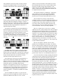
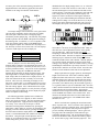
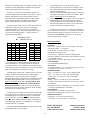
2002.11.01
User's Manual - MODEL EFI
Multifunction Instrument
Thank you for purchasing the EFI (Electronic Flight
Instrument) by Taskem Corp. Please take a few moments to
read this manual thoroughly to get the most out of your
purchase.
The multifunction EFI is available in a small rectangular
format and a larger round package that includes magneto test
switches. Other than the magneto test switches, both formats
are functionally identical. Both units simultaneously display
all of the following data on a large, two-line liquid crystal
display (LCD). Referring to the figures, the functions are;
engine RPM, AUX, two exhaust gas temperatures (EGT), two
cylinder head (CHT) or one Coolant temperature, Altitude,
Climb rate and Flight Time. The unit also displays total
accumulated engine time (Hobbs) at the push of a button. The
LCD contrast can be adjusted from the normal seating position
with the up/dn switch and provides a clearly readable display
over a wide range of viewing angles. In addition, the LCD is
backlighted for night viewing.
The AUX function is extremely versatile in that it can be
used to display volts, fuel level, oil pressure, oil temperature,
outside air temperature or any other desired parameter.
The top four functions each have a REDLINE associated
with them, and the redline settings can easily be displayed and
changed. REDLINE settings, Flight Time and Hobbs time are
retained in permanent memory which does not need power, so
no data is ever lost due to a battery failure. Exceeding a
REDLINE setting causes the high intensity, red WARNING
light to flash and the associated LCD value to blink. Pressing
the Lmts switch stops the WARNING light, but the LCD
characters still blink until the situation is corrected.
The unit can be powered from either of two DC sources
selected by the three position, on-off-mom(entary) Power
switch. The on position is typically used to operate the
instrument from 12V and the momentary position from two
optional 9V alkaline batteries. If running a basic craft with
only a rectifier/regulator (no 12V battery), the 9V batteries can
be used to power the instrument when the engine is not
running. This allows the user to observe the last flight time,
total engine time or other settings without having to start the
engine. The spring-loaded momentary position insures that the
switch is turned off when done to conserve 9V battery life.
The 9V batteries are not used for data retention and are not
needed if 12V power is available from a battery.
When first turned on the unit displays; 1) an introduction,
2) an option to adjust the contrast, 3) a preflight checklist, 4)
the measurement units, 5) an option to view and set the
REDLINES and 6) the normal instrument functions. The first
word of the introduction rolls in one character at a time. You
can get directly into the instrument functions by pressing the
LMTS pushbutton while this first word is rolling in.
If the introduction is not interrupted, the CONTRAST
ADJUST feature will be displayed as shown on the following
page. LCDs exhibit a notable change in contrast depending on
the angle (above or below) from which they are viewed. The
up/dn switch is used at this point to adjust for the best contrast
and should be done while in the normal, seated position.
Pressing and releasing the switch will change the setting by
one increment, while holding the switch in either position will
make it change continuously. Try to obtain the greatest
contrast possible without allowing the unused segments to
become visible. Once adjusted, pressing the
manner, set the EGT and CHT/Coolant redlines as needed.
Press the Lmts button once more to exit the redlines routine
and a brief "SAVED" message will be displayed. This
indicates that all of the redline settings have been saved in
memory. It then enters the normal instrument functions that
are explained in detail as follows.
Lmts pushbutton will store the setting in memory and then
proceed to the preflight checklist. If you wish to skip the
preflight list and go directly to the instrument functions simply
The tachometer displays in 10 RPM steps. Although all
data is updated every 0.6 seconds, the displayed RPM is
actually an average of the last 4 readings. This serves to
smooth out some of the jitter that would otherwise be seen.
shut the instrument off then turn it on again. The newly stored
contrast setting will remain in effect and you can then press the
Lmts button while the introduction is rolling in. A taller or
shorter pilot may have to readjust the contrast as a result of the
different viewing angle. Also, temperature affects the contrast
somewhat and it may require adjustment if subjected to a
significant temperature change.
The AUX function is extremely versatile and with
compatible "senders", can be used to display any parameter. It
is a voltage driven device, where a voltage in the range of zero
to a positive value can be made to display 00 to 99 on the
LCD. Many senders such as the popular capacitance fuel
probes output zero volts for an empty tank and either +5V or
+12V for a full tank. Thus, they are fully compatible.
The operator is required to press the Lmts pushbutton to
advance through each of the preflight checks. After the last
check, the unit temporarily displays what units are in use then
prompts the operator to press the Lmts button to see the
current REDLINE settings. If the switch is not pushed within
2 seconds, the unit then displays the normal instrument
functions. If the switch is pushed, the instrument displays the
following.
Since it is a voltage device, it can serve as a voltmeter
without the need for a sender, and this is how units are shipped
unless otherwise specified when ordered. As a voltmeter, the
AUX displays the DC voltage that is being used to power the
instrument. It is a simple two-digit meter with the lesser digits
"truncated". This means that the decimal digits are there, you
just can't see them. Thus, 11.9 volts will be displayed as 11,
and 12.1 volts will show as 12. It can also be adjusted to
round to the nearest volt if desired. For instance, 12.4 volts
would display 12 and 12.6 would show 13. This requires only
a simple calibration adjustment.
Since the AUX display is limited to 00 to 99, many
parameters are best displayed as a percentage. For instance,
fuel level would typically be displayed as 00 for empty and 99
for full. It is interesting to note that this could also be applied
to its use as a voltmeter. While charging, a typical lead acid
battery will actually measure about 14 volts. If desired, the
AUX function could be configured so that 14V is displayed as
99 (a full battery) and all other readings would be reflected as
percent of full. In this case 75% would indicate about 10.6V.
The RPM redline value is displayed and can be changed
with the up/dn switch. Pressing the Lmts pushbutton then
advances to the next redline item. Note that once you press the
Lmts switch to move forward, you can't go backwards. If you
skip by a desired redline item, you will have to turn the
instrument off and on again and start all over.
To use the AUX function to display anything other than the
voltage that powers the instrument an internal jumper must be
moved. Refer to the board layout diagram on page 4 for
jumper locations. Jumper plugs are accessible by shutting off
power to the instrument then removing three Philips head
screws that secure the back cover in place. Observe the
caution on the back label. A piece of cellophane tape covers
the opening below the connector and can easily be removed. It
should be replaced with new tape when reassembled. Jumper
J10 provides a simple means to alternately connect the AUX
measurement circuits to either the external connector or to the
internal +12V power. It can be placed in either of two
positions, A or B as shown in diagram on the following page.
Jumpers are easily lifted with fingernails or long nose pliers.
In the A position the AUX circuits are connected to the DC
voltage that powers the instrument. Moving the jumper to the
B position connects the AUX
Since AUX can be used for any of several parameters, it
requires both LOWER and UPPER redline settings. For
instance, if AUX were used as a fuel gauge, a LOWER redline
makes sense, to warn of low fuel. If AUX were used as an oil
temperature indicator, the UPPER redline would be
applicable. Some parameters can use both. For instance, as a
voltmeter, a low redline setting of about 11 would warn of a
discharging battery, while an upper redline of 16 would warn
of a runaway rectifier/regulator that will eventually "fry" a
perfectly good battery. To disable the LOWER AUX redline
set it to zero.
Once the LOWER AUX redline is set, press the Lmts
button to proceed to the UPPER AUX and set as desired. To
disable the UPPER AUX redline set it to 99. In a like
(2)
threshold where the display changes from 13 to 14. This will
insure that 14.2 volts reads 14 and 13.8 volts reads 13. Press
the Lmts button again to exit the calibrate mode and save the
result in memory. Note that if the calibration is done with fullscale voltage, there is the possibility that the display will
appear to be stuck at 99 when first entering the calibration
mode. If so, just continue holding the switch down until the
readings start to change. If it seems to take forever, it may be
better to first do the calibration at half-scale (just to get it in
the ballpark), then repeat it with full-scale again afterwards.
circuits to pin 8 of the connector allowing external access.
Supplied harnesses and connector pigtails have this input
available on an orange wire labeled "AUX INPUT".
AUX input voltages from less than one volt to greater than
100 volts can be adjusted to cause a full-scale (99) reading.
This wide span is achieved in three overlapping ranges,
selectable by another jumper plug. One (and only one) jumper
should be placed in the LO, MED or HI position according to
the following table. For instance, if +12V is to produce a fullscale AUX reading, put the jumper in the MED position.
Units shipped to operate as a voltmeter have the jumper set to
HI. This may not seem correct at first, but if 14 volts displays
14, then it would require 99 volts to display 99.
Jumper
LO
MED
HI
When using the AUX as a fuel gauge with a capacitance
fuel sender it is necessary to first adjust the sender. Many of
these have one or more adjustments of their own (typically
zero and full-scale). These must be done first, before
attempting to calibrate the AUX. Follow the directions that
came with the sender. Once that is complete, then perform the
following steps to calibrate the AUX fuel display. For best
results this should be done with a full tank. With the jumpers
set as needed, turn the instrument on and wait for the AUX
reading to stop changing. Enter the calibrate mode by pressing
and holding the Lmts button as previously described. Use the
up/dn switch to make the AUX value read 98. Press the Lmts
switch to exit the calibrate routine and save the adjustment.
Full-scale Volts
0.84 to 4.74
4.12 to 23.3
20.3 to 115
After the jumper is set to the desired range, the AUX
function must be calibrated. The instrument does not have to
be open for this procedure. It need only be done once, as it is
stored in permanent memory. The process involves applying a
known voltage, entering the CALIBRATE mode then
adjusting the up/dn switch to display the desired value. The
following should be considered when doing the adjustment.
Input voltages that exceed full scale are displayed as 99. As
such, if the internal AUX value is actually 125, it will still
show 99. There is no way of knowing if a display of 99 is
truly 99 or a greater value. To avoid this problem, it's a good
practice to set the AUX to show 98 if calibration is done with
full-scale voltage applied. Also, calibration does not require
that full-scale voltage be applied. It is only necessary to apply
a known voltage then calibrate the AUX to display the proper
number in response to that voltage.
Simple capacitance fuel gauges operate by measuring the
height of fuel in the tank. If the tank is uniformly shaped
height and volume will be the same. However, if the tank is
irregularly shaped, 50% will not represent half of the actual
fuel. It's a good idea to then drain fuel out 'till you get to the
point where you would like to trip the fuel redline (typically 1
to 1.5 gallons, whatever you feel comfortable with). Once this
is done, turn the instrument on and allow the AUX fuel reading
to fully stabilize and record the reading. Then turn the
instrument off and on again and enter the REDLINES routine.
Set the LOWER AUX redline to the recorded value. Now,
whenever the fuel falls below this level, the redline will be
exceeded and a warning given. The UPPER AUX redline
should be set to 99.
The following procedure explains how to calibrate the
AUX to read 14 when 14V is applied, as with a voltmeter.
This is only used as an example. The same procedure applies
to all other applications. Apply the known voltage (in this
case exactly +14.0 volts) to the AUX input. Turn the
instrument on and bypass the introduction by pressing the
Lmts button. Wait a minute or so for the AUX reading to stop
changing. Enter the calibrate mode by pressing and holding
the Lmts button in until the display blanks, then immediately
release it. The EFI should then look similar to the diagram
that follows. Using the up/dn switch, adjust the AUX to
display 14. For maximum accuracy try to find the up/dn
switch setting that is just one "click" above the
There is one final issue regarding the AUX function and
that is "response time". This is a measure of how quickly the
AUX display responds to changing values. Some applications
require a very slow response time (long-term average) to
prevent constantly fluctuating displays. This is typical of a
fuel gauge where the sloshing fuel would otherwise give
continually changing values. The AUX function includes a
selection of SLOW or FAST response time made by jumper
J6. See the table on page 5 that describes jumper use. You
(3)
should use FAST response time whenever possible and that is
how units are shipped for the voltmeter application. If the
AUX data exhibits jitter, change to SLOW. Use SLOW for
fuel gauge applications.
INSTALLATION:
Successful installation requires attention to both wiring and
mechanical details. The unit incorporates four, captive, 8-32
lock nuts for mounting. It is intended to be mounted from
behind the instrument panel. Four, large head, stainless steel
panel screws are supplied eliminating the need for washers.
There is no need for lock washers or to over tighten the
screws, as the lock nuts are very effective. If it is desired to
mount the unit to the front of the panel, the captive nuts can
easily be removed.
EGT is displayed for two cylinders on a time-shared basis.
Each is continuously monitored, but they are alternately
displayed for about 5 seconds each. An underline “_” is
present just to the right of the EGT field when cylinder #2 data
is displayed. If the engine is at ambient temperature (has not
been started), then EGT will display the ambient air
temperature. However, since the EGT probes and circuitry are
calibrated at a much higher temperature where it normally
operates, such readings can be inaccurate. Another jumper J5
selects one or two cylinder temperature operation. When set
for one cylinder, the display does not alternate as described
above, and cylinder #2 is disabled.
The optional wiring harness has critical wires clearly
labeled and greatly simplifies installation. It incorporates an
in-line fuse to protect the instrument from damage, which is
typically encountered if the aluminum case of the instrument
accidentally comes into contact with 12V power. This is most
likely during a “hot” insertion into the instrument panel.
Although the instrument draws only a small current, the fuse
must also supply the starter solenoid coil current and any DC
accessories. Fast blow, 3 to 5A fuses are appropriate.
The next field displays either two CHTs or one Coolant
temperature. Jumper J4 makes the selection. If CHT is
selected, the underline described above indicates cylinder #2
as before. If Coolant is in use, the underline has no meaning
as only one coolant temperature is measured and displayed.
There is only one REDLINE value for the CHT/Coolant field,
so it has to be set accordingly.
Each of the harness wires is labeled with a tag indicating
where it should be connected. The GROUND wire should be
securely fastened to the engine block. Others are clearly
obvious, and a wiring diagram is included if more detail is
needed. If coolant temperature is not used (CHT selected),
cover and secure the coolant temperature (H2O) wire. If CHT
is not used, each of the two CHT wire pairs must be “shorted”
together. Simply plug the male connector into the female
connector on each of the two CHT wire pairs then tape them
out of the way. THIS IS VERY IMPORTANT. Failure to
do this may result in erratic readings.
While displaying normal instrument functions, the
altimeter value can be changed using the up/dn switch. It is
typically set to read known field altitude above sea level or
zero before take off. The setting is maintained in memory so it
will not have to be readjusted if the unit is turned off then on
again. It should not be adjusted in flight unless accurate
altitude can be received via radio. Many ultralight pilots
prefer to zero an altimeter at their field. This is sometimes
impossible for high altitude fields or requires the instrument to
be opened to make internal adjustments. This altimeter can be
zeroed for field altitudes up to 6000 feet above sea level
directly from the front panel. Since it is a pressure device it
will require adjustment from day to day as the local barometric
pressure changes.
Once all wires are correctly connected, plug the 15-pin
harness connector into the mating socket on the instrument.
Don’t force it in. If it offers any resistance, just work it back
and forth a bit ‘till it goes in smoothly. Secure the connector
to the instrument with the two jackscrews that are part of the
connector hood. Don’t over tighten, but make sure they are in
properly and secure. If applicable, mate the 3-pin nylon
Climb rate (vertical speed) is displayed in the next field. It
is calculated by measuring changes in altitude over a few
seconds. When the instrument is first turned on altitude will
typically take a few seconds to settle to a final value. As a
result, the climb rate will not zero until a few seconds after the
altimeter settles.
Flt. Time reflects either the current flight time (engine
running) or the last flight time (engine stopped). The timer is
reset to zero and starts incrementing each time the tachometer
senses an RPM, so it actually represents engine time rather
than flight time. If the tachometer is not working for any
reason (broken tach wire), the Flt. Time will not work either.
Data is retained in permanent memory, so if you forgot to enter
the last flight time in your log, it’s still there and will be
displayed as long as you don’t restart the engine. Pressing the
Lmts switch momentarily replaces the Climb and Flt. Time
fields with total accumulated engine (Hobbs) time.
(4)
connector to the mating plug for the magneto switches. These
switches are totally independent of the EFI circuitry and are
located on the panel only for convenience.
1.
Jumpers J1, J2 and J3 select the number of pulses per
revolution (PPR) that the tachometer circuit expects. This is a
function of the number of poles in the magneto. Ducati
ignitions produce 6 PPR and the majority of other engines
such as Zenoah, Kawasaki, and Hirth (and earlier Rotax
engines without the Ducati ignition) produce 2 PPR.
3.
2.
4.
5.
Jumper J4 selects either CHT or Coolant (H2O) modes for
temperature. With J4 in place, the unit is set to display
Coolant temperature. The J5 jumper is used to disable
cylinder #2 temperatures. This is for single cylinder engines,
to prevent the alternating display. A storage location is
supplied for unused jumpers.
Turn instrument power on. Press button to get by
checklist, then wait 1-2 minutes for all readings to settle.
Press AND HOLD the Lmts button ‘till display blanks,
but DON’T RELEASE IT.
About 15 seconds after the display blanks, the word “GO”
will appear in the upper left corner of the display. When
it does, immediately release the pushbutton.
If done properly, the altitude display will now be replaced
with atmospheric pressure in inHg (typical values are
29.XX) and all EGT/CHT values will now read ambient.
Press the Lmts button once more to get out of this mode
and store calibration constants in memory.
As with any electronic device, care should be taken not to
leave it exposed to the elements. It is not waterproof and may
sustain permanent damage if exposed to rain or salt air. The
instrument should NEVER be transported or left outside
uncovered, particularly overnight.
JUMPER SETTINGS
! = JUMPER IN PLACE
SPECIFICATIONS:
J1
J2
J3
!
!
!
!
!
!
!
!
!
!
!
!
PPR
0.5
1
1.5
2
3
4
5
6
J4
!
J5
!
J6
!
TEMP
H2O
CHT
#CYL
1
2
TIME
SLOW
FAST
GENERAL
• Size. 6 3/8” diameter or 4 x 5 7/8" rectangle. 2 3/4” deep.
• Operating voltage. 11 to 28VDC.
• Current drain. Less than 50mA @ 13.8VDC.
• Backlighted for night viewing.
• LCD Contrast. Adjustable in normal seating position.
• Memory. Redlines, timers & other critical functions retained
in permanent memory.
• Tach & Timer Accuracy. Better than 0.04% of reading.
TACHOMETER
• 0 to 9990 RPM in 10 RPM steps.
AUX INPUT
• Two digit resolution. 0 to +X volts displays as 0 to 99. X is
adjustable from <1 volt to >100 volts.
TEMPERATURES
• EGT. 0 to 1800°F in 5° steps. Type K thermocouple.
• CHT. 0 to 700°F in 1° steps. Type J thermocouple.
• COOLANT. 7 to 340°F in 1° steps. VDO sender.
ALTITUDE
• Range. -1,000 to +30,700 feet in 10 foot increments.
• Accuracy. Better than ±50 feet once zeroed or set to actual
field altitude.
• Barometric reference. Adjustable over a wide range. Allows
zeroing for field altitudes to +6000 MSL.
CLIMB RATE
• 0 to ±8000 feet per minute in 100 fpm steps.
• Proprietary smoothing filter removes excessive jitter.
TIMER FUNCTIONS
• Flight time. 0 to 9:59 in one minute steps.
• Total time. 0 to 9999.9 hours in 0.1 hour steps.
Internal jumper settings are marked on the label on the
back of the main unit. Any changes should be marked (in
pencil) on this label, so the configuration can be determined
without having to open the instrument. Refer to the label when
using a new instrument to determine the settings.
Standard practice with pilots of small aircraft is to keep the
avionics and radios OFF until the engine reaches normal
operating speed. This is because there are potentially
damaging voltage spikes while the starter is cranking and when
the engine idles down when shut off. This same practice is
highly recommended for the EFI. ALWAYS SHUT THE
INSTRUMENT OFF WHILE YOU START OR SHUT
DOWN THE ENGINE. Failure to do so may damage the
instrument or alter EGT & CHT calibrations, timer and other
data stored in the computer memory.
The procedure to recalibrate the instrument and insure that
the proper calibration constants are in memory is listed below.
You should not have to do this unless there is evidence that
there is a problem. A problem is evident when, with engine
dead cold and not running, both EGTs don’t read ambient or
read considerably different. A 15°F difference is acceptable.
A 200°F difference is a problem.
Phone: 508-679-9339
Fax: 508-646-2755
www.taskemcorp.com
The engine MUST BE DEAD COLD when doing this else
the calibration will not work properly.
(5)
Taskem Corporation
12 Tickle’s Road
Westport, MA 02790
(6)
TROUBLESHOOTING GUIDE
FAULTY EGT OR CHT TEMPERATURES:
EGT and CHT probes are constructed from two dissimilar metals welded together at the probe tip (a thermocouple). These
provide a very accurate means of sensing temperature, but unfortunately, their lifetime is limited. This is especially true for EGT
probes, since in addition to constant stress from repeated expansion and contraction, they are subjected to much higher temperatures.
Eventually, the welded joint separates at elevated temperatures, giving completely erratic temperature readings. Coolant temperature
probes are constructed differently and rarely fail. The majority of problems encountered with the EFI are related to faulty EGT or
CHT probes or their associated wiring. This guide attempts to educate the pilot so that he or she may diagnose and rectify these types
of problems with confidence.
A typical complaint heard from flyers is "the red warning light started flashing and the EGT was flashing too". After seeing
this condition, the inexperienced pilot often performs an immediate landing, assuming that there is something drastically wrong with
the engine and seizure is eminent. Here are some DOs, DON’Ts and helpful advice on how to analyze the problem and correct it. The
following presumes the problem is with one of the EGTs, but the same information applies to the CHTs too.
•
•
First, DON'T PANIC! Press the Lmts pushbutton to stop that annoying red light, then take a moment to look at the display and
evaluate what it's telling you. Which of the two EGT temperatures is the offender (flashing on and off), cylinder 1 or 2? The EGT
and CHT displays continuously alternate between cylinder 1 and 2, showing each for about 5 seconds. Cylinder 2 temperatures
have an underline after the EGT and cylinder 1 does not.
Next, is the offending temperature steady or is it jumping a hundred degrees or more? If it's jumping all over the place it's pretty
certain that it's a bad probe or probe wiring; engine temperatures simply can't change that quickly. If the flashing temperature is
steady and not jumping, then it's possible that the system is telling the truth and you may have an engine problem and should
consider a precautionary landing and engine shutdown.
If a temperature was jumping drastically, it's most likely a bad probe but it could also be faulty probe wiring.
•
•
The wires in the harness are color coded and labeled. Each of the EGT and CHT probes connects to a paired set of wires, one
white and one colored. EGT1 - yellow, EGT2 - red, CHT1 - blue, CHT2 - green. Although the engine manufacturer regards a
specific cylinder as "cylinder 1", the instrument does not know which is which. Instrument cylinder number references are only
linked to the color of the harness wires. Also, each of the wire pairs has a male/female set of "bullet" connectors with mating
connectors on the probes. These will be unplugged for troubleshooting, but be sure to use pliers to grip them, since they are quite
difficult to pull apart. Pulling on the wires is sure to break them.
Unplug each of the EGT probes from the harness wires and connect them to the other set of harness wires (i.e. plug the probe that
was connected to the yellow/white wires into the red/white wires and vice versa). If EGT1 was flashing, and EGT2 was giving a
steady and normal reading, then swapping the probes should swap the problem (EGT2 now jumping and EGT1 steady). If this
happens then you have positively identified and localized a bad probe. Replace the faulty probe.
Note that a faulty probe will usually behave well at low temperatures and it's only when brought up to normal operating
temperature that it will fail. You will most likely have to start the engine and bring it up to normal operating temperature to see the
problem again and see if it "swapped cylinders."
If the jumping temperature DID NOT swap positions, then it's likely that you have faulty wiring in the harness.
•
Unplug the suspected bad probe and plug the two harness bullet connectors into each other, then start the engine up again. You
will now have no probe on that circuit and the temperature should consistently show the air temperature (ambient) without any
drastic fluctuations, regardless of the engine temperature. If the temperature fluctuates wildly like it did in flight, it's likely that
there's a faulty connection on one of both of the harness wires (white and colored). Check the crimps at the bullet connectors and
make sure they are secure. Pull on them a bit and make sure the wire doesn't pull out. This type of problem will usually show up
at any temperature 'cause the faulty connection is not temperature dependent like a bad probe but brought about by vibration. Also
check for loose or broken wires or crimps inside the 15-pin connector that plugs into the instrument.
If the suspect temperature is not intermittent, but steadily reads high, then it's possible that the instrument or engine is at fault. The
most common instrument fault is associated with improper software calibration of the EGT and CHT temperatures and can easily be
corrected by you. If the following software calibration is found to be O.K., then believe the instrument and probe, they are telling the
truth - your engine has a problem.
(7)
•
•
The EGT and CHT temperatures all have a room temperature error that must be measured and stored in memory. This error is
then taken into consideration by the computer to give correct readings at all temperatures. It's kind of like a bathroom scale that
reads 10 pounds even before you step on it. You first "zero" the scale by adjusting the offset knob and all readings are then O.K.
The EGT and CHT are calibrated in the same way except that the offset is not "zeroed" but rather adjusted to read correctly at
room (ambient) temperature. The calibration is stored in "non-volatile" memory. This means that the memory normally can not
be changed, but under certain extreme circumstances, it may get altered and require calibration. This is usually caused by faulty or
intermittent 12V power, and for this reason we recommend that the instrument not be powered while cranking the starter. It can
also be caused by intense radio frequency interference from a radio transmitter in very close proximity to the EFI or by radio
frequency emissions from a very noisy magneto circuit.
The key to determining if the instrument requires EGT/CHT calibration is to look at these temperatures at ambient temperature.
It's a good practice to regularly check the EGTs (and CHTs if used) before starting the engine. When the engine is cold it is at the
same temperature as its surroundings. Under these circumstances, both EGTs (and CHTs) should read ambient. If they all read
approximately correct and within 15º of each other, then all is O.K. But, if one or more of the temperatures read some ridiculous
value like 400º when they should be reading 80º, then the instrument must be calibrated. Follow the instructions on page 5. Note
that this must be done with the engine at ambient temperature - dead cold. (You can't zero the bathroom scale while you're
stepping on it!)
EGT OR CHT DISPLAYS 0° AFTER ENGINE IS WARM:
If you purchased probes and harness direct from us, they have polarized plugs and can only be connected correctly. If you
didn't buy from us there is the possibility of connecting probes backwards (with polarity reversed). If an EGT or CHT reads correct at
ambient temperature but decreases and stops at 0º when the engine is started, that's a sure indication that the probe is connected
backwards. Reverse the leads.
INSTRUMENT WILL NOT TURN ON:
The two 9V batteries are only needed in aircraft that do not have 12V battery power available. They allow these aircraft to
power the instrument momentarily without having to start the engine. They are used for no other purpose and have nothing to do with
memory retention, however they can be a useful tool. If the instrument will not turn on when the power switch is placed in the upper
(on) position install two 9V batteries and try powering the EFI from the spring-loaded mom(entary) position. If the EFI comes on
normally, it's pretty certain that you are not getting 12V to the instrument. Check the in-line fuse and associated 12V wiring.
CHT/COOLANT DISPLAYS 7° AT ALL TIMES:
If the EFI is set to display coolant temperature and a coolant sender is not connected, the unit will display 7°. Check that a
coolant sender is connected to the heavy white wire and if so, check the integrity of the wiring. This will also happen when the EFI is
internally set to display coolant but you really want CHT temperatures. Since you most likely have no coolant sender connected, the
unit will display 7°. Remove internal jumper J4 to set the instrument to display CHT vice coolant.
TACH PROBLEMS:
The tach input to the instrument is the gray harness wire. This must be connected to some suitable engine source. Most
Rotax engines have a mating gray wire on the engine for this purpose. The engine's lighting coil is another good source of a suitable
tach signal, but this can only be used if a simple rectifier/regulator is also connected since it provides the "ground reference" for the
tach signal. In this case, connect the harness gray wire to either of the heavy yellow lighting coil wires.
If you get no tach indication at all check the wiring and instrument with an ohmmeter. Don't use an old-fashioned moving
needle type meter. Many of these output high voltage that can damage sensitive electronics. Use a modern digital-type ohmmeter or
multimeter. Disconnect the harness gray wire from the engine and measure its resistance to ground with the instrument off. It should
read approximately 48KΩ.
If the tach reads consistently (no jumping) but is in error across the entire speed range, the internal jumpers that select the
pulses per revolution (ppr) are probably set wrong. Rotax 503/582 gray wire and lighting coils output 6ppr. The 912 engines output 5
ppr on their lighting coil and 1 ppr at the tach drive coil. The 912 tach coil is "floating", so one side must be grounded and the other
connected to the harness gray wire. Many other makes output 2ppr at their lighting coils. Experiment. Try different ppr settings until
the tach displays the right rpm. Note that you must turn the instrument off then on again when changing the ppr jumpers, as the
computer reads them only when power is first turned on. Call us for ppr info on other engines.
(8)