1
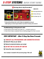
E-STOP SYSTEMS
QUICK START GUIDE
1 Power In
2 Power Out
Customer’s
ELECTRICIAN
connects to
IPM (load)
here
Connects to power source:
110v, 240v Single Phase –
20 AMP Max if needed
Customer’s ELECTRICIAN
connects 3-phase
power here – 100 AMPs Max
UNIT MUST HAVE 3-PHASE POWER* TO WORK
Connect 110v / 240v IPM machines (load) here
*Unit can be configured 240v, 380v, 480v, 575v
3 All black receptacles must
be filled with “dummy
plug” or daisy chain
4 Don’t force connectors!
NOTCH ALWAYS UP
Dummy
plug or
daisy
chain if
equipped
Align notch
and slide in
Notch
always up
Closeup of Dummy Plug
E-Stop buttons or accessories
(Do not need all white receptacles filled)
CONFIDENTIAL
Copyright © 2012 In-Place Machining Company
Dummy plugs are
kept in pouch in
yellow bag
Version: 1.2
08/27/2012
E-STOP SYSTEMS
QUICK START GUIDE
5 E-Stop Start-Up Procedure*
–SINGLE UNIT–
Red Light On
1
Red Light On
Push Start –
Green Light On
1
Pull Emergency Buttons Out
2
2
Push Green Start Light
3
Verify Amber Light is On
3
Amber Light Turns On
*If using multi-unit daisy chain, verify all steps are completed on each unit
– Amber lights go on when all green buttons are pushed in the daisy chain scenario
Troubleshooting if E-Stop doesn’t start:
• Check that all STOP buttons are pulled out – red lights must be on
• Check that all black receptacles have something plugged into them correctly
VERY IMPORTANT - After E-Stop Has Been Pressed:
1) TURN OFF ALL IPM MACHINES AND CONNECTED DEVICES
2) Restart E-Stop as per above
3) Restart connected devices as normal
4) DO NOT USE AS AN ON-OFF SWITCH
5) Test at the start of each job!
User manual is located in the accessory bag of the unit
CONFIDENTIAL
Copyright © 2012 In-Place Machining Company
Version: 1.2
08/27/2012