1
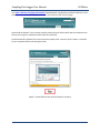
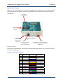
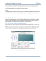
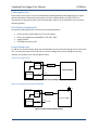
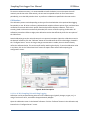
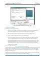
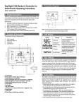
UserManual CO2SamplingDataLoggerNEMA4 MetersCovered CM‐0052 CM‐0132 CM‐0152 CM‐0153 CM‐0154 CM‐0155 Copyright © 2015 CO2 Meter. All Rights Reserved. SamplingDataLoggerUserManual CO2Meter Welcome Thank you for purchasing our meter. CO2Meter, Inc. is a Florida based business specializing in the design and manufacturing of gas detection and monitoring devices – mainly CO2. Our approach is one based in the science of gas and how best to accurately and repeatedly measure that gas for the end users purposes. Our business partners in agriculture, HVAC, science, safety, research, pharmaceuticals, beverage, and other fields find our devices to be highly accurate and cost effective. We approach each customer’s application as a unique opportunity to understand, educate, and provide product solutions that meet the customers’ needs while exceeding their expectations for reliability and service. Our continued product innovation in combination with our “customer first” focus allows CO2Meter, Inc. to continue to provide solutions for the future. Based in Ormond Beach, FL, CO2Meter, Inc. is committed to the success of our customers; the health, welfare, and prosperity of our talented employees; and the continued development of our local community. CO2Meter, Inc. appreciates your business and looks forward to working with you and your team in the future. Please take some time to read through this manual in order to become familiar with the meter. Also, please pay special attention to the important safeguards shown on the next page. PAGE2 of16 SamplingDataLoggerUserManual CO2Meter TableofContents METERSCOVERED........................................................................................................................................... 1 WELCOME .......................................................................................................................................................... 2 IMPORTANT SAFEGUARDS ................................................................................................................................. 4 DEVICE SPECIFICATIONS ..................................................................................................................................... 5 PACKAGE CONTENTS .......................................................................................................................................... 6 OPTIONAL ACCESSORIES .................................................................................................................................................. 6 GASLAB® SOFTWARE .......................................................................................................................................... 6 MINIMUM SYSTEM REQUIREMENTS ................................................................................................................................... 6 QUICK START GUIDE ........................................................................................................................................... 8 POWER SOURCE ............................................................................................................................................................. 8 OUTPUTS AND CABLE LEGEND .......................................................................................................................................... 8 SETUP .......................................................................................................................................................................... 9 Data Logging Configuration .................................................................................................................................. 9 POWERING THE UNIT .................................................................................................................................................... 10 LCD DISPLAY (IF APPLICABLE) ......................................................................................................................................... 10 USAGE (PUMP ONLY) .................................................................................................................................................... 10 Closed Loop Operation ........................................................................................................................................ 10 Open Loop with Environmental Exhaust ............................................................................................................. 10 THEORY OF OPERATION ................................................................................................................................................. 11 0‐1% and 0‐30% Units Only ................................................................................................................................. 11 CALIBRATION ............................................................................................................................................................... 12 0‐1% or 0‐30% Sampling Unit with Data Logging ............................................................................................... 12 CALIBRATION PROCEDURE .............................................................................................................................................. 13 0‐5%, 65%, 100% Sampling Unit with or without Data Logging ......................................................................... 13 Zero or Fresh Air Calibration ............................................................................................................................... 14 High‐Concentration Calibration .......................................................................................................................... 14 TROUBLESHOOTING GUIDE ............................................................................................................................... 14 SUPPORT .......................................................................................................................................................... 15 WARRANTY ....................................................................................................................................................... 15 LIABILITY ........................................................................................................................................................... 15 RETURNS .......................................................................................................................................................... 15 CONTACT US ..................................................................................................................................................... 16 PAGE3 of16 SamplingDataLoggerUserManual CO2Meter WARNING! InstallGasLab®softwarebeforeconnectingyourCO2Meterproduct(s) toyourcomputer.FailuretodosomayaffecttheabilityforGasLab®to detectyourmeter/sensor.Ifthishappens,pleasefollowtheinstructions showninthe“Error!Referencesourcenotfound.”sectiononpageError! Bookmarknotdefined.ofthismanual. ImportantSafeguards To reduce the risk of fire, electrical shock and/or injury to persons, basic safety precautions should always be followed when using electrical appliances, including the following: 1. 2. 3. 4. READ ALL INSTRUCTIONS BEFORE USING THIS METER. INSTALL GasLab® SOFTWARE BEFORE CONNECTING METER TO A COMPUTER. Use only the included power supply to operate this meter. Make sure that the tubes are securely attached to the meter before sampling a closed environment (CM‐0045‐NM‐SP model only). 5. Do not operate with an obstructed sample path (CM‐0045‐NM‐SP model only). 6. Do not operate this meter if the enclosure is opened. 7. Do not operate the device if it is malfunctioning. SAVE THESE INSTRUCTIONS! PAGE4 of16 SamplingDataLoggerUserManual CO2Meter DeviceSpecifications Measuring Range: 1% CO2 0‐10,000 ppm (0‐1% vol.) 5%, 30%, 65%, 100% CO2 0‐5%, 0‐30%, 0‐65%, or 100% vol., respectively Accuracy (all ranges) ±0.5%, ±3% measured value Power Supply: Maximum Voltage 30VDC Minimum Voltage 18VDC Power Consumption ~1Watt avg. (pump running) Sensor Ratings: Life Expectancy >15 years Maintenance Interval No maintenance required Warm‐up Time <1 min (instant measurements) Pump Characteristics: Maximum Flow (STP) 800 ml/min Maximum Vacuum 52% Maximum Pressure 600 mbar restart, 150 mbar continuous Maximum System Pressure ~1 ATM Outputs: Range 0‐100% vol. Output Value 4‐20mA, linearly scaled Relay COM, NC, NO 1A @ 30VDC RS‐485 Modbus interface PAGE5 of16 SamplingDataLoggerUserManual CO2Meter PackageContents Please verify that your package contains the following items before using the meter: All units: (1) NEMA Sampling Meter (1) 6‐foot USB Cable (1) M12, 12‐positions 5M cable (1) Fitting, tubing & filter kit (1) User manual Figure 1 OptionalAccessories If not included, you can purchase an Extreme Moisture filter separately. These filters are ideal for high‐ humidity environments to allow air flow while keeping humidity out. Use anywhere humidity is very high (> 95%). SKU #CM‐0103. GasLab®Software IMPORTANT: MAKE SURE TO INSTALL SOFTWARE BEFORE CONNECTING YOUR METER TO YOUR COMPUTER MinimumSystemRequirements To utilize our free software, the computer must meet the following minimum requirements: 1GHz processor with 1GB RAM, 1GB free disk space (2GB free disk space for 64‐bit systems). Windows XP*/7/8/8.1 with Microsoft .NET Framework 4.0** or later. On Intel‐based Mac computers, GasLab® software can run using a Windows 7/8 virtual machine software such as VMware Fusion® or similar. *Microsoft .NET is not supported on Media Center or Tablet editions. **Installer will optionally install .NET Framework. PAGE6 of16 SamplingDataLoggerUserManual CO2Meter Visit www.co2meter.com/pages/downloads to download our complimentary GasLab® software to your computer. You can also download the GasLab®’s user manual in PDF from this page. Please read the GasLab®’s user manual carefully to become more familiar with how the software works so that you can get the maximum benefit from this useful tool. Install the GasLab® software first to ensure that the proper driver, necessary for the meter, is installed on your computer before connecting the meter. Figure 2: Install GasLab online (Internet Explorer 9 shown) PAGE7 of16 SamplingDataLoggerUserManual CO2Meter QuickStartGuide Make sure you read through these instructions thoroughly before using your meter. This guide will help you familiarize with your meter in order to be as productive as you need to be in the least amount of time possible. Pump Switch Turns pump on/off Power Switch Turns the unit on/off Barb Fittings Figure3: Components Connect to sampling system for closed Mini USB Port M12 Connector loop sampling Connect to PC for meter 12‐pin RS‐485 connection for 24VDC power configuration, data source and controller interface (for PLC, transfer, and USB charging MODBUS, etc.) PowerSource These meters are powered by connecting to a suitable 24VDC power source. This is very convenient for permanent installations. OutputsandCableLegend Pin # Wire Color Color Legend Description 1 Brown CO2 4‐20mA‐ 2 White CO2 4‐20mA+ 3 Blue NO Relay 4 Pink NC Relay 5 Yellow CM Relay 6 Red Voltage Input 7 Black Power Ground 8 Grey Not Connected 9 Purple Not Connected 10 Green RS‐485 Ground 11 Pink/Grey RS‐485 B 12 Red/Blue RS‐485 A Table 1: Cable legend. PAGE8 of16 SamplingDataLoggerUserManual CO2Meter These meters feature a 4‐20mA linearly scaled output that matches the current CO2 concentration reading proportionally. In addition, it has a digital RS‐485 interface for connection to a MODBUS network and one relay with 1A @ 30VDC for an external controller. Setup Our sampling device will require minimal setup since it is designed to be portable. The most important aspect of the setup involves connecting the sampling hoses and ensuring proper environmental setup. Figure above shows the labeled components of the unit, as referenced throughout the rest of this manual. DataLoggingConfiguration These meters feature an internal memory capable storing data when not attached to a personal computer. These units will allow you to simultaneously read and store CO2 concentration level data. Due to the nature of their design, these units should be connected to your personal computer first, before operation, to initialize and set the logging period, and real‐time clock. 0‐1%,5%,30%,65%,100%CO2SamplingDataLoggers Make sure the unit is powered with 24VDC using the RS‐485 cable included. In order to initialize data logging functionality, the unit MUST be connected to the computer with data logging switched to off, and the GasLab® software started. Once the unit has been connected, click on the “Configure Sensor” button in the GasLab® interface, set the data logging interval and pump periods as desired. Figure 4: Collecting data in real time PAGE9 of16 SamplingDataLoggerUserManual CO2Meter PoweringtheUnit These meters have a switch on the front dedicated to enabling/disabling data logging (right on Figure above) and another dedicated to powering the unit (left on Figure above). As long as the unit is connected to an appropriate power source and the power switch is in its ON position, the unit will be operating properly. LCDDisplay(ifapplicable) The Liquid Crystal Display (LCD) screen shows the following features: CO2 in parts‐per‐million (ppm) for 1% and 5% models CO2 in percentage format (##.##%) for 30%, 65%, 100% Logging On/Off Percentage of memory free Usage(Pumponly) In order to use the unit, hoses/tubing must be attached to the inlet and outlet fittings on the front of the unit. The pump will draw air from the inlet in a vacuum configuration, push it through the sensing chamber, and exhaust the air out through the outlet. ClosedLoopOperation Figure 5: Closed loop sampling setup OpenLoopwithEnvironmentalExhaust Figure 6: Opened loop sampling setup PAGE10 of16 SamplingDataLoggerUserManual CO2Meter Figure 7: Filter Installation and Orientation. We recommend installing the included humidity/particulate filter to ensure the sensing chamber and pump baffle stays clear and corrosion free. TheoryofOperation The CO2 sensor inside this device uses non‐dispersive infrared technology to sense, as a function of transmitted light, the concentration of CO2 in the air. It has been factory‐calibrated to operate within the specified range and precision. 0‐1%and0‐30%UnitsOnly The sensor uses an algorithm called Automatic Background Calibration (ABC) to continuously adjust the zero‐point to ensure accuracy is maintained. This is required to compensate for sensor drift, which occurs normally on these units. The primary contributor to sensor drift is the normal and unavoidable aging of the infrared light source within the sensor. The ABC algorithm allows the CO2 sensor to dynamically shift its CO2 reading by a constant. It works via storing the lowest CO2 sample taken over the ABC period and assuming that this low value is equal to a known value (the target value). It then adjusts the output of the CO2 reading by the delta between these values. This algorithm does not affect the linearization of the output signal. For example, the ABC algorithm is enabled by default, with an ABC period of 180 hours, a target value of 400ppm, and a maximum delta of 30ppm. This operates under the principle that a CO2 level in ambient outdoor air is 400ppm. The sensor will keep track of the lowest CO2 reading recorded over a period of 180 hours and then adjust the zero point based on the lowest CO2 level recorded, up to 30ppm at a time, towards that value. PAGE11 of16 SamplingDataLoggerUserManual CO2Meter To ensure maximum accuracy, it is recommended to install the device in an environment that will routinely see this low value. Alternatively, the unit can be exposed to fresh air for a few minutes periodically, or set the ABC period to 0 sec. to perform a calibration as specified in the next section. Calibration The calibration process varies depending on the type of unit and whether it has optional data logging functionality or not. All units are factory‐calibrated with multiple reference points of gas, and have been verified to be accurate within their specific functionality before shipment. However, if the unit is severely jolted or otherwise mechanically disturbed, the sensor can drift requiring recalibration. All calibration procedures follow a single‐point calibration routine that effectively shifts the zero‐point of the CO2 sensor. Attach calibration gas to the unit and connect it to a personal computer. Open the calibration screen in the GasLab® software. Click the “Calibrate” button in the calibration tab for the desired gas, located in the “Configure Sensor” screen. As long as the gas concentration is stable, the unit should instantly reflect the calibrated value. This can be confirmed by watching the display. To see the calibration value in real time, click in the “Collect Real time” button to capture these values before opening the configuration screen. Figure 8: Real‐time capture 0‐1%or0‐30%SamplingUnitwithDataLogging Calibration can be performed using either 0% CO2 calibration gas (typically nitrogen, argon, etc.), or using a fresh source of air, assumed to be approximately 400ppm. Open the calibration screen in the GasLab® software. Click the “Calibrate” button in the calibration tab, located in the “Configure Sensor” screen. PAGE12 of16 SamplingDataLoggerUserManual CO2Meter FIF Figure 9: Data logger calibration screen for 0‐1% CO2 CalibrationProcedure To calibrate your unit, follow these steps: 1. Expose the unit to ambient air (assumed to be at 400ppm) or connect it to a calibration gas bottle/cylinder (100% nitrogen or argon) with the appropriate demand regulator. 2. Wait 25 seconds to collect a sample. Write down this value as the “before” value. 3. Click the “Calibrate” button after selecting your calibration gas. 4. Wait 25 seconds again. This time, the unit will take a sample and use this data to adjust zero values. The displayed measurements will reflect the new calibration value (0 or 400ppm). 5. Disconnect the calibration gas and wait 25 seconds. The newly displayed data will now reflect the new sensor calibration. If the sensor is still operating outside of its specified range, repeat this procedure. When the readings vary too greatly, the calibration will silently fail and may need to be performed again. 0‐5%,65%,100%SamplingUnitwithorwithoutDataLogging These units do not feature Automatic Background Calibration (ABC) algorithm due to the CO2 scale they measure. To ensure the highest accuracy, we recommend calibrating these units with calibration gas (nitrogen for zero, or CO2), close to the concentration being measured. Alternatively, a 0% or ambient calibration can be performed. To perform a calibration, attach the unit to your computer, power it and either expose it to atmosphere or supply it with your calibration gas, fed with a demand‐based regulator. PAGE13 of16 SamplingDataLoggerUserManual CO2Meter Open the GasLab® software on your personal computer and click the “Configure Sensor” button. For data logging units, click the “Turn Pump on Continuously” button to ensure continuous flow. (To apply any changes, the unit has to power cycle). ZeroorFreshAirCalibration Apply gas and select the appropriate concentration in the screen shown in Figure above. Click the “Calibrate” button. The sensor reading should instantly reflect the calibration. High‐ConcentrationCalibration Write down the original Zero Value before adjustment for future reference. Apply the desired concentration calibration gas; adjust the Zero Value in increments of 10 pressing scroll, put the right value of the calibration gas and click on the “Calibrate” button. Wait until the unit displays the correct concentration level, then close the window by clicking on the “Save” button. NOTE: DO NOT ADJUST THE SPAN VALUE. Troubleshootingguide Symptom/ Issue PossibleCause/Resolution Device/Sensor isnot recognizedby PC Devicedoesn’t powerON TheGasLab® software doesn’tstart*1 Makesurethecablewires(seeTable 1onpage8) areconnectedtoasuitable24VDCpowersupplyor thattheUSBcableisproperlyconnectedtoa computer. Performresolutionaboveandmakesurethat thereisadequatepowertothemeter. Yoursoftwaremightbeoutofdate.Updateyour softwarebyeithervisitingourdownloadwebpage athttp://www.co2meter.com/pages/downloads orbyselectingthe“CheckforUpdates”underthe Helpmenu.MakesureyourPCmeetstheminimum requirements. Checktheairflowchannelstomakesuretheyare notobstructed. Calibrationorrecalibrationneeded. Slowresponse Reading doesn’tchange *1FormoretroubleshootingtipsonGasLab®pleasedownloadtheGasLabusermanualat http://www.co2meter.com/pages/downloads. PAGE14 of16 SamplingDataLoggerUserManual CO2Meter Support The quickest way to obtain technical support is via email. Please send all support inquires to [email protected]. Please include a clear, concise definition of the problem and any relevant troubleshooting information or steps taken so far, so we can duplicate the problem and quickly respond to your inquiry. Warranty This meter comes with a 1YEAR (warranty period) limited manufacturer’s warranty, starting from the date the meter was shipped to the buyer. During this period of time, CO2Meter.com warrants our products to be free from defects in materials and workmanship when used for their intended purpose and agrees to fix or replace (at our discretion) any part or product that fails under normal use. To take advantage of this warranty, the product must be returned to CO2Meter.com at your expense. If, after examination, we determine the product is defective, we will repair or replace it at no additional cost to you. This warranty does not cover any products that have been subjected to misuse, neglect, accident, modifications or repairs by you or by a third party. No employee or reseller of CO2Meter.com’s products may alter this warranty verbally or in writing. Liability All liabilities under this agreement shall be limited to the actual cost of the product paid to CO2Meter.com. In no event shall CO2Meter.com be liable for any incidental or consequential damages, lost profits, loss of time, lost sales or loss or damage to data, injury to person or personal property or any other indirect damages as the result of use of our products. Returns If the product fails under normal use during the warranty period, a RMA (Return Material Authorization) number must be obtained from CO2Meter.com. After the item is received CO2Meter.com will repair or replace the item at our discretion. To obtain a RMA number, call us at or email us at (386) 256‐4910 [email protected]. When requesting a RMA please provide reason for return and original order number. If the product fails under normal use in the first 10 days of ownership, at our discretion we will email you a postage‐paid UPS label to return the product at our expense. If we determine that the product failed because of improper use (water damage, dropping, tampering, electrical damage etc.), or if it is beyond the warranty date, we will inform you of the cost to fix or replace the product. PAGE15 of16 SamplingDataLoggerUserManual CO2Meter ContactUs We are here to help! For information or technical support, please contact us. [email protected] (386) 256‐4910 ( Technical Support) (386) 872‐7665 (Sales) PAGE16 of16