1
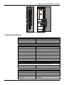
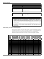
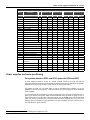
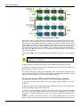
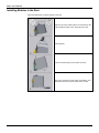
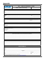
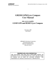
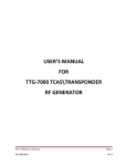
USER’S MANUAL
Power Supply for Backplane
20 - 30 Vdc
D F
5
6
M E
smar
www.smar.com
Specifications and information are subject to change without notice.
Up-to-date address information is available on our website.
web: www.smar.com/contactus.asp
DF56 – Power Supply for Backplane 20 – 30 Vdc
AVOIDING ELECTRICAL DISCHARGES
ATTENTION
Electrostatic discharges may damage semiconductor electronic components in printed circuit
boards. They usually occur when touching components or connector pins from modules and racks,
without wearing the appropriate equipment to prevent discharges. It is recommended to take the
following precautions:
•
Before handling modules and racks, remove the electrostatic charge from your body by
wearing a proper wristband or touching grounded devices;
•
Avoid touching electronic components or connector pins from racks and modules.
3
DF56 – User’s Manual
DF56 – POWER SUPPLY FOR
BACKPLANE 20 – 30 VDC
Description
This redundant power supply works independently or with another redundant power supply module
to assure a constant power supply to the application. When two redundant power supply modules
are used, both split the energy that is needed to supply the system. When one power supply fails,
the other, automatically, will assume the operation. Each power supply has a relay to indicate
failures allowing the user to replace damage modules.
This module has two voltage outputs:
a) 5 Vdc @ 3A distributed by Power Lines in the Inter-Module-Bus (IMB) through racks to supply
module circuits.
b) 24 Vdc @ 300mA for external use through terminals 1B and 2B.
The DC applied voltage and the 5Vdc and 24 Vdc are isolated.
Installation and Configuration
For systems based on DF92 and DF93 racks, with DF90 and DF91
Redundant mode
Splitting Power concept: In this situation, two modules will supply power to a bus segment. If one
of them was turned off or fails, the other power supply must be able to supply energy, alone, to the
segment.
Expansion of load capacity by adding power supplies or pairs of redundant power supplies
If the system consumption is greater than 3A, it can be subdivided in up to 8 groups sized for
consumption of up to 3A each, and each group is individually powered by a power supply, or
redundant pair of power supplies. More details on the Power supplies positioning topic.
Power supplies positions in the racks
On DF92, the pair of redundant power supplies must be installed in the first and second slots.
On DF93 is recommended the placement of the redundant pair in the first and second slots, but it
can be installed in any slots if necessary.
Configuration of CH1 jumper
The DF56 CH1 jumper always must be connected to the R position.
For systems based on DF1A and DF78 racks
Single Module: Less than 3 A are required.
There is an address restriction related to the location of the power supply. This restriction is the first
rack (address 0) must have a power supply module in the first slot. The CH1 jumper (power supply)
must be set in the E position.
More Than One Module: More than 3 A are required.
For systems based on DF1A rack they must be placed in the first slot of the rack. Jumper W1 on
the rack that has the new power supply must be cut. Every new power supply will only supply
energy to the rack in which it is located and, with the jumper cut off, it will not supply energy to the
previous racks. All modules must have the CH1 jumper (power supply) set in the E position.
Redundant Mode:
In redundant mode, the power supply modules must be placed in the first and third slots of rack
DF1A or first and second slots of rack DF78. In both, the CH1 jumper (power supply) must be set in
the R position. In this condition, the power supply modules will split the power. This topology is
called “split power mode”.
4
DF56 – Power Supply for Backplane 20 – 30 Vdc
DC LINE
DC Power Supply for Backplane
+24VDC
Air convection
do not obstruct
air flow!
DC-R/56
DC Power Supply for Backplane
DF56
+5VDC
Operating Range
-10ºC to 60ºC
14ºF to 140ºF
OUTPUT
24VDC
300mA
1B
2B
6W
30VDC Max.
200mA Max.
Fail
V
3B
4B
5B
20-30VDC
Max. 42W
6B
7B
FUSE
2.5A
See
manual
smar
BRN04
DC Power Supply: DF56
Technical Specifications
INPUTS
20 to 30 Vdc
DC
Inrush Current
Maximum Consumption
Indicator
< 20.6 A @ 30 Vdc [ ΔT < 430 µs]
42 W
DC LINE (Green LED)
a) Output1 (Internal Use)
Current
Ripple
Indicator
Hold up Time
b) Output 2 (External Use)
Current
Ripple
Indicator
Short Circuit Current
OUTPUTS
5.2 Vdc +/- 2%
3 A Maximum
100 mVpp Maximum
+5 Vdc (Green LED)
> 47 ms @ 24 Vdc [Full Load]
24 Vdc +/- 10%
300 mA Maximum
200 mVpp Maximum
+24 Vdc (Green LED)
700 mA
ISOLATION
Input signal, internal outputs and the external output are isolated between them.
Between Outputs and Ground
500 Vrms
Between Input and Output
1500 Vrms
FAILURE RELAY
Type of Output
Solid state relay, normally closed (NC), isolated
Limits
6 W, 30 Vdc Max, 200 mA Max
Maximum Initial Contact Resistance
<13 Ω
Overload Protection
Should be provided externally.
Operation Time
5 ms maximum
5
DF56 – User’s Manual
TEMPERATURE
Operation
-10 ºC to 60 ºC (14 ºF to 140 ºF)
DIMENSIONS AND WEIGHT
39.9 x 137.0 x 141.5 mm
Dimensions (W x H x D)
(1.57 x 5.39 x 5.57 in)
Weight
0.450 kg
CABLES
One Wire
14 AWG (2 mm2)
Two Wires
20 AWG (0.5 mm2)
NOTES
1. If the power consumption exceeds the power supplied, the DFI302 system may operate in an
unpredictable manner that may causes damages to the equipment or risk of personal injury.
Therefore, the power consumption must be calculated correctly and a detailed analysis should
be performed to define the installation of extra power supply modules.
2. The hardware revisions which are GLL1279 Rev1 and previous revisions do not support
redundancy feature.
3. To meet the EMC standards requirements, the wires’ length to the failure relay must be less
than 30 meters. The power supply of activated load by the failure relay must not be from
external network.
Calculating the Power Consumption
Since the power available in the power supply is limited, it is important to calculate the power
consumption of modules in use. The user can create a worksheet to summarize all supplied and
required current from each module and associated equipment (such as operator interface).
Example of worksheet with the module’s consumption, and some power supplies’ specification.
DFI302 Power Budget
Module
6
Description
Qty.
1
Consumption
Unit Power (mA) Total Power (mA)
Supply
Unit Power (mA)
Total Power (mA)
@24 V
@24 V
@24 V
@5 V
@24 V
@5 V
DF51
Controller
0
950
0
950
DF62
Controller
0
550
0
0
DF63
Controller
0
550
0
0
DF73
Controller
0
650
0
0
DF75
Controller
0
550
0
0
DF11
2*8 DI 24 Vdc
0
80
0
0
DF12
2*8 DI 48 Vdc
0
80
0
0
DF13
2*8 DI 60 Vdc
0
80
0
0
DF14
2*8 DI 125 Vdc
0
80
0
0
DF15
2*8 DI 24 Vdc (sink)
0
80
0
0
DF16
2*4 DI 120 Vac
0
50
0
0
DF17
2*4 DI 240 Vac
0
50
0
0
DF18
2*8 DI 120 Vac
0
87
0
0
DF19
2*8 DI 240 Vac
0
87
0
174
2
DF20
8 switches
0
45
0
0
DF44
8 AI
0
320
0
0
DF57
8 AI
0
320
0
0
@5 V
@5 V
DF56 – Power Supply for Backplane 20 – 30 Vdc
DFI302 Power Budget
Module
Description
Qty.
Consumption
Unit Power (mA) Total Power (mA)
Supply
Unit Power (mA)
Total Power (mA)
@24 V
@24 V
@5 V
@24 V
@5 V
3000
@5 V
@24 V
@5 V
DF45
8 Temperature inputs
0
55
0
0
DF21
16 DO (transistor)
65
70
0
0
DF22
2*8 DO (transistor)
65
70
0
0
DF23
8 DO (triac)
0
70
0
0
DF24
2*8 DO (triac)
0
115
0
0
DF25
2*4 DO (relay)
134
20
0
0
DF26
2*4 DO (relay)
134
20
0
0
DF27
2*4 DO (relay)
134
20
0
0
DF28
2*8 DO (relay)
180
30
0
0
DF29
2*4 DO (relay)
134
20
0
0
DF30
2*4 DO (relay)
134
20
0
0
DF31
2*4 DO (relay)
134
20
0
0
DF46
4 AO
180
20
0
0
DF32
8 DI 24 Vdc, 4 DO (relay)
67
60
0
0
DF33
8 DI 48 Vdc, 4 DO (relay)
67
60
0
0
DF34
8 DI 60 Vdc, 4 DO (relay)
67
60
0
0
DF35
8 DI 24 Vdc, 4 DO (relay)
67
60
0
0
DF36
8 DI 48 Vdc, 4 DO (relay)
67
60
0
0
DF37
8 DI 60 Vdc, 4 DO (relay)
67
60
0
0
DF38
8 DI 24 Vdc, 4 DO (relay)
67
60
0
0
DF39
8 DI 48 Vdc, 4 DO (relay)
67
60
0
0
DF40
8 DI 60 Vdc, 4 DO (relay)
67
60
0
0
DF53
4 Fieldbus Power
Impedance
1500
0
1500
0
1500
1074
1
TOTAL
4
DF50
1
300
3000
300
DF52
1
1500
0
1500
0
TOTAL
6
1800
3000
Power supplies and racks positioning
For systems based on DF92 and DF93 racks with DF90 and DF91
A power supply connected to a rack, in a system, provides current to the racks row that are
horizontally interconnected to it by their terminals of lateral connections, and vertically through DF90
cables, thus forming a group of rows of racks that use the same power supply.
The system can have only one power supply (or pair of redundant power supplies) or it can be
subdivided in several of these groups1, each one powered by a power supply (or pair of redundant
power supplies).
The recommended way to distribute the power is to divide the system in groups of horizontal rows of
racks. In this scheme, each power supply must be positioned on the top left of the group of rows of
racks that it powers. The rack were is the power supply must be the W1 jumper cut and the DF90
cable must not be connected to the rows powered by other power supplies (top rows). See in the
following figure an example of system powered by two power supplies, each one powers a part of
rows represented in green and blue.
1
Maximum 8 groups allowed when the DF56 power supplies are used.
7
DF56 – User’s Manual
System powered by two power supplies
Note that this system, for greater efficiency, is optimized for power distribution by groups of rows of
racks. Thus, a power supply powers a whole number of rows it supports. However, in rare cases,
with long rows or many modules with great consumption in the same row, there is the option to add
power supplies in the middle of the row, dividing the power within this row. In this case, the power
supply added powers only the modules positioned on the right in the same row, up to the end, or
even where there is another power supply added. In the rack where the power supply was added, in
this scheme, the W1 jumper must be cut and left lateral connection terminal (+5 Vdc) must be
disconnected (collapsed).
In this system, DF56 must be its CH1 jumper always configured in R, even if it is not in redundant
pair.
ATTENTION
A mixture of these power supplies with the CH1 configured in R and in E in any
DFI302 system, is not allowed!
On DF92, the pair of redundant power supplies must be installed in the first and second slots.
On DF93 is recommended the placement of the redundant pair in the first and second slots, but it
can be installed in any slots if necessary.
The system has diagnostic for voltage level distributed to racks. It also supports modules with great
power consumption in any place on the bus. Nevertheless, is recommended to place those modules
close to the power supplies, to avoid unnecessary power transmission.
For systems based on DF78 and DF1A Racks (legacy systems)
1. Observe the maximum current values from the power supply module specification. The limit for
DF56 is 3 A.
2. After the connection with long cables (DF4A, DF5A, DF6A and/or DF7A) you have to put another
power supply module in the first slot of the first rack.
3. Use up to 6 modules DF44/DF57 per power supply; always place consecutively the DF44/DF57
and close to the power supply. Because of the high current consumption of the modules
DF44/DF57, a not desired voltage drop in the bus can occur if these modules are placed after other
modules.
4. When is necessary to add interface modules, such as HI302, MB700, DF58, in the same bus
which is used by output and input modules, is recommended that these modules are placed close to
8
DF56 – Power Supply for Backplane 20 – 30 Vdc
the power supply, because in the same way as described in the previous item, a not desired voltage
drop in the bus can occur if these modules are placed after other modules.
5. Adding a new power supply module
• Determine the rack where the new power supply will be installed.
• Cut the jumper W1 of the rack.
• Plug the new power supply at the first slot of the rack (slot 0).
• In this case, the CH1 jumper of all modules DF56 must be set in E position.
9
DF56 – User’s Manual
Installing Modules in the Rack
Follow the steps below to install a module in the rack.
Attach the top of the module (with a 45o inclination) to the
module support located on the upper part of the rack.
Mounting detail.
Push the module fixing it to the module connector.
Next, fix the module to the rack using a screwdriver, and
fasten the fixation screw at the bottom of the module.
10
Appendix
SRF – SERVICE REQUEST FORM
DFI302 – Fieldbus Universal Bridge
Proposal Nº:
COMPANY INFORMATION
Company: _____________________________________________________________________________________________________
Unit: ________________________________________________________________________________________________________
Invoice: _______________________________________________________________________________________________________
COMMERCIAL CONTACT
Full Name: ____________________________________________________________________________________________________
Phone:
_________ _________________________ _________ _________________________ Fax: _______________________
E-mail: _______________________________________________________________________________________________________
TECHNICAL CONTACT
Full Name: ________________________________________________________________________________________________
Phone: _________ _________________________ _________ _________________________ Extension: ____________________
E-mail: _______________________________________________________________________________________________________
EQUIPMENT DATA
Model:
______________________________________________________________________________________________________
Serial Number: ________________________________________________________________________________________________
PROCESS DATA
Process Type (Ex. boiler control): __________________________________________________________________________
Operation Time: ____________________________________________________________________________________________
Failure Date: __________________________________________________________________________________________________
FAILURE DESCRIPTON
(Please, describe the failure. Can the error be reproduced? Is it repetitive?)
______________________________________________________________________________________________________________
______________________________________________________________________________________________________________
______________________________________________________________________________________________________________
______________________________________________________________________________________________________________
OBSERVATIONS
______________________________________________________________________________________________________________
______________________________________________________________________________________________________________
______________________________________________________________________________________________________________
______________________________________________________________________________________________________________
USER INFORMATION
Company: _____________________________________________________________________________________________________
Contact: _______________________________________________________________________________________________________
Section: _______________________________________________________________________________________________________
Title: ________________________________________________
Phone: _________ _________________________
Signature:_______________________________________________
_________ _________________________
E-mail: ________________________________________________________________________
Extension: ___________________
Date: ______/ ______/ _________
For warranty or non-warranty repair, please contact your representative.
Further information about address and contacts can be found on www.smar.com/contactus.asp
A.1
DF56 – User’s Manual
A.2