1
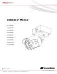
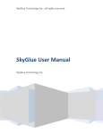
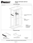
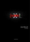
Installation Manual Wide Angle Models: AV2225PMIR AV2225PMIR-A AV2226PMIR AV3225PMIR AV3226PMIR AV3226PMIR-A AV5225PMIR AV5225PMIR-A AV10225PMIR Telephoto Models: AV2225PMTIR AV2226PMTIR AV3225PMTIR AV3226PMTIR AV5225PMTIR AV10225PMTIR Telephoto Model Wide Angle Models Arecont Vision MegaView® 2 Installation Manual MegaView® 2 Installation Contents Package Contents ................................................................................................................................................... 3 Warranty Information .............................................................................................................................................. 4 Install MegaView® 2 Camera ................................................................................................................................. 5 Replacing the IR LED board: ............................................................................................................................... 10 Camera Software Installation .............................................................................................................................. 11 Electrical Box Adapter (SV-EBA) Installation Instructions (Sold Separately) .............................................. 13 Pole Mount Adapter (MD-PMA) Installation Instructions (Sold Separately) ................................................. 14 Corner Mount Adapter (MD-CRMA) Installation Instructions (Sold Separately) ......................................... 15 LED Indicators (Camera Signal) ......................................................................................................................... 16 Support ................................................................................................................................................................... 17 Mounting Template ............................................................................................................................................... 18 Page | 2 [email protected] Arecontt Vision Me egaView® 2 Installatiion Manua al Package Co ontents MegaV View® 2 Camera C Package: Arecont A Visio on MegaView w® 2 Camera a Ju unction box adapter Mounting M Tem mplate for Ju unction box adapter ® Mounting M Tem mplate for MegaView M 2 Camera CD C with AV10 00 software and user ma anuals (licen nse key requ uired for reco ording) Security S L-ke ey Pack P of four (4) ( screws and a four (4) anchors NOTE: N Ancho ors and scre ews are good d to be used d for concrette, wall blockk and red briicks. NOTE: N Screw ws by themselves can be e used in wo ood. H. Rubber R plug I. Pack P of four (4) ( machine screws, #8--32, ½” Philliips Pan Hea ad A. B. C. D. E. F. G. A D Image 1 Page | 3 support@arecontv vision.com C B E F G H I Arecont Vision MegaView® 2 Installation Manual Warranty Information 3 Year Limited Warranty ARECONT VISION warrants to Purchaser (and only Purchaser) (the “Limited Warranty”), that: (a) each Product shall be free from material defects in material and workmanship for a period of thirty-six (36) months from the date of shipment (the “Warranty Period”); (b) during the Warranty Period, the Products will materially conform with the specification in the applicable documentation; (c) all licensed programs accompanying the Product (the “Licensed Programs”) will materially conform with applicable specifications. Notwithstanding the preceding provisions, ARECONT VISION shall have no obligation or responsibility with respect to any Product that (i) has been modified or altered without ARECONT VISION’s written authorization; (ii) has not been used in accordance with applicable documentation; (iii) has been subjected to unusual stress, neglect, misuse, abuse, improper storage, testing or connection; or unauthorized repair; or (iv) is no longer covered under the Warranty Period. ARECONT VISION MAKE NO WARRANTIES OR CONDITIONS, EXPRESS, IMPLIED, STATUTORY OR OTHERWISE, OTHER THAN THE EXPRESS LIMITED WARRANTIES MADE BY ARECONT VISION ABOVE, AND ARECONT VISION HEREBY SPECIFICALLY DISCLAIMS ALL OTHER EXPRESS, STATUTORY AND IMPLIED WARRANTIES AND CONDITIONS, INCLUDING THE IMPLIED WARRANTIES OF MERCHANTABILITY, FITNESS FOR A PARTICULAR PURPOSE, NON-INFRINGEMENT AND THE IMPLIED CONDITION OF SATISFACTORY QUALITY. ALL LICENSED PROGRAMS ARE LICENSED ON AN “AS IS” BASIS WITHOUT WARRANTY. ARECONT VISION DOES NOT WARRANT THAT (I) THE OPERATION OF THE PRODUCTS OR PARTS WILL BE UNINTERRUPTED OR ERROR FREE; (II) THE PRODUCTS OR PARTS AND DOCUMENTATION WILL MEET THE END USERS’ REQUIREMENTS; (III) THE PRODUCTS OR PARTS WILL OPERATE IN COMBINATIONS AND CONFIGURATIONS SELECTED BY THE END USER; OTHER THAN COMBINATIONS AND CONFIGURATIONS WITH PARTS OR OTHER PRODUCTS AUTHORIZED BY ARECONT VISION OR (IV) THAT ALL LICENSED PROGRAM ERRORS WILL BE CORRECTED. For RMA and Advance Replacement information visit ArecontVision.com Page | 4 [email protected] Arecontt Vision Me egaView® 2 Installatiion Manua al Install Mega aView® 2 Came era Mounting the Camera: C 1. Remo ove camera and hardwa are from the box. 2. Use the t mounting g template (Image 1-C),, to prepa are the moun nting provisions for junc ction box adapter a insta allation. N NOTE 1: Wa ater damage e from impro oper iinstallation is not covere ed by the wa arranty! N NOTE 2: Usse of silicon o on the RJ45 5 connector w without juncction box ada apter does n not g guarantee a water resistant install. ¾” NPT Pipe 3. Attac ch provided Junction J Box x Adapter (Imag ge 1-B) to th he wall using g appropriate e hardw ware. NOTE E: Hardware e, provided with w the unit,, is only suitable s for surfaces s liste ed on page 3. ove the cond duit plug on Junction box 4. Remo adapter and conn nect ¾” NPT T conduit pip pe to apter shown in Image 2.. Juncttion Box Ada age 2 Ima NOTE E: Use silico on or water pipe p seal tap pe to ma ake sure no water leakag ge between conduit pipe and junction box x adapter. 5. Run Ethernet E cab ble and othe er cables (if neces ssary) through the Junction Box Adap pter and conn nect to Mega aview® 2 pig gtail cable e as shown in Image 8. age 3 Ima 6. Add provided p rub bber plug (Im mage1-H) on n the bracket to ensure a water tight utdoor applic cations as installlation for ou show wn in Image 3. 7. Organize pigtail cable c and atttach ® Mega aView 2 cam mera to Junction Box Adap pter using pro ovided screw ws (Image 1-I) 1 as sh hown in Imag ge 3-1 and Image I 4. Imag ge 3-1 Page | 5 support@arecontv vision.com Arecontt Vision Me egaView® 2 Installatiion Manua al N NOTE 1: Bra acket screw ws are all seccurity screws s tthat are tam mper-resistan nt. N NOTE 2: Bra acket with 3 axes enable es easy iinstallation in any locatio on, including g 360° ccamera body dy rotation, 9 90° tilt, 360° bracket rrotation. (Im mage 7) Image 4 8. Use the security y L-key to ad djust ® Meg gaView 2 brracket to app propriate position. ( Image e 5) 360° 360 0° 90° age 7 Ima N NOTE 3: Me egaView® 2 iis a total PoE class 3 ssolution to p power the ca amera, IR illu uminator and d ffan. Fan is a always on. Image 5 CAU UTION: Only y adjust the screws s with an arrow pointing to o them on th he bracket ba ase dy (Image 6)) and camera bod N NOTE 4: To o use the extternal powerr, 12-48VDC C o or 24VAC, p power on cam mera, conne ect external p power with p pigtail cable connector ((Image 8) N NOTE 5: On nly MegaView® 2 –A aud dio models h have female e 3.5mm aud dio in / out ja ack. Arrow A Digital In PoE RJ45 5 Audio Out Aud dio In Auxiliary PPower Adjusttable Screwss Image 6 Image 8 Page | 6 support@arecontv vision.com Arecont Vision MegaView® 2 Installation Manual Optional: Connecting Digital I/O: 9. To use digital I/O, connect digital I/O with pigtail cable connector as shown in Image 8. NOTE 1: MegaView® 2 only supports digital input but no digital output. Input voltage (V) (measured between + and – terminals) Min Max ON 2.9 6.3 OFF 0 1.3 OFF - 0.1 Table 1 NOTE 3: The digital input is electrically isolated from the rest of the camera’s electrical circuitry via general-purpose photo couplers. The input is additionally protected with a serial 250 Ohm resistor, and a debouncing circuit. Duration of any input signal should be at least 5 ms to comply with the requirements of the debouncing circuit. NOTE 4: Table 2 shows cable color for digital input Green Black Digital IN + Digital IN - Table 2 NOTE: MegaView® 2 camera operating temperature is -40˚C (-40 °F) to +50˚C (122 °F), however, motorized lens operating temperature is -20˚C (-4°F) to +50˚C (122 °F). 10. To adjust focus or zoom, open the camera web interface and click the “Focus” tab as shown in image 9. NOTE 2: Table 1 shows electrical characteristics Electrical Characteristics: Adjusting the Remote Focus and Remote Zoom: 11. To manually adjust zoom, click the “+20”, “+5”, “+1”, “-20”, “-5”, “-1” buttons to zoom in and out, adjusting the field of view. NOTE 1: “+20” zooms in 20x further than “+1” NOTE 2: If the “Enable Auto Focus after zoom” option is checked as shown in image 8, the focus will automatically be adjusted when zoom is changed. 12. Set up a focus area (if necessary) by drawing a rectangle with the mouse (by leftclicking and dragging the mouse to a desired zoom size) shown in Image 8. 13. To automatically adjust focus, choose “Fullrange Focusing” or “Fast Focusing” depending on the image clarity as shown in image 8. 14. If the image is completely out of focus, choose “Full-range Focusing” to scan the full focus range and find the best focus position. 15. If the image is slightly of out of focus, choose “Short-rang Focusing” to fine tune and quickly get a precise focus position to save time. Page | 7 [email protected] Arecont Vision MegaView® 2 Installation Manual 16. To manually focus, click the “+20”, “+5”, “+1”, “-20”, “-5”, “-1” buttons to fine tune the focus. Image 9 Adjusting P-Iris: Note: If “Enable P-Iris” is unchecked, the iris will be fully open to the maximum. It may result in less sharpness and artificial color under strong light condition. Image 9-1 Page | 8 [email protected] Arecont Vision MegaView® 2 Installation Manual Optional: Enable Audio: 17. Connect a mono analog microphone to Microphone In and connect an active speaker with a built-in amplifier via the inline jack as shown in Image 8, if needed. 18. Choose “H.264 over RTP/UDP” as shown on Image 10-1 and check “Enable Microphone” then click “Preview” and “Apply” buttons as shown on Image 10-2. NOTE: Audio only works in H.264 RTP/UDP streaming Image 10-1 Page | 9 [email protected] Image 10-2 . Arecontt Vision Me egaView® 2 Installatiion Manua al Repla acing th he IR LED boa ard: 19. Unsc crew glass rin ng (Image 11) P screw wdriver to re emove IR LE ED 20. Use Phillips board d (Image 12)) eplace IR LE ED board, un nplug cable and a 21. To re replace new IR LED L board (Image 12-1) NOTE: IR R LED board d part numbe er: M000094 4-34 Imag ge 12 Image 11 Imag ge 12-1 Page | 10 [email protected] Arecont Vision MegaView® 2 Installation Manual Camera Software Installation 22. Install the AV100 application manager Software. (Image 13, found on the CD). 25. Click “Mode” tab to select desired install mode on the Arecont Vision Camera Installer as shown in Image 16. 23. Run the AV100 application manager by double clicking on the icon shown below. (Image 14, found on your desktop). NOTE 1: Advanced Mode: (Default setting) software will automatically discover but allow manual update of the IP address. See “AV100 Installation Manual” (found on the CD) for details on Advanced Mode. NOTE: you can download latest version AV100 on website http://www.arecontvision.com/softwares.php NOTE 2: Basic Mode: software will automatically discover and change / assign IP address to match PC subnet if they are not locked. NOTE3: User can verify camera model number and FW version of all cameras as shown in Image 16. Image 13 Image 14 24. Select “Run” next to “Setup Cameras” from the AV100 application manager as shown in Image 15 and wait for “Arecont Vision Camera Installer” window to appear as shown in Image 16. Image 16 Image 15 Page | 11 [email protected] 26. select “Find Cameras” on the Arecont Vision Camera Installer as shown in Image 16. Arecont Vision MegaView® 2 Installation Manual 27. Confirm that all the cameras connected to the network switch appear in the upper window. 28. Repeat Step 24 if all of the cameras do not appear in the upper window. CAUTION: If the software does not find a camera, the software utility may be blocked by the anti-virus or Windows® firewall. Before turning them off, please consult your IT manager. NOTE : Double click the camera model on the Camera Installer as shown in Image 17 to access the camera web interface. See “AV Camera Web Page User Manual” (found on the CD) for details on the web interface. Image 17 29. When all cameras are discovered and display “Installed, online”, select “Save/Exit.” The AV100 application main menu will appear. 30. From the “AV100 Application Manager” menu, select “Run” next to “Live video” to view live images. NOTE: See the “AV100 Installation Manual” (found on CD) for details on camera configurations. Page | 12 [email protected] Electtrical Bo ox Ada apter (S SV-EBA A) Installation IInstructions (Sold d Separrately) Inside th he box: A. Electrical E Box x Adapter B. Pack P of four (4) ( machine screws (#8--32 7//16”) A Me egaView® 2 Braacket holes Ima age 18-1 Single gang b box Junctiion box adapteer holes B Image 18 Imag ge 18-2 Dou uble gang box uded but ne eeded: Not inclu Common C elec ctrical box, such s as sing gle gang box, double gang box, or squarre xes shown in n Image 18-1 1~4. electrical box 1. move the elec ctrical box adapter and Rem hard dware from the box. 2. Attac ch the wall mount m bracket to the elec ctrical box ad dapter. 3. Attach adapter to t electrical box. b IImage 18-3 Square box x IImage 18-4 Square box x Arecontt Vision Me egaView® 2 Installatiion Manua al Pole Mount Adapte er (MD--PMA) Installation Ins structio ons (Sold d Separrately) Inside th he box: A. B. C. D. E. Pole P Mount Adapter A 2x x Compress sion Fittings 2x x Small Stee el Straps 2x x Large Stee el Straps Pack P of four (4) ( machine screws (#8--32 5//8”) Not inclu uded but ne eeded: 5. Run Ethernet Ca able and other cables (if essary) throu ugh the Juncction Box nece Adap pter and con nnect to Meg gaView® 2 pigta ail cable. 6. Attacch MegaView w® 2 bracket to Pole Moun nt Adapter a as shown in Image 21. SV-EBA S (Elec ctrical box adapter) a d two Steel S Straps to 7. Use the supplied Mount Adaptter to the attacch the Pole M pole and tighten the compression screw ws as shown n in Image 2 21. D C E A NOTE: U Use silicon o or water pipe e seal tape to make sure no watter leakage b between conduit p pipe and jun nction box ad dapter. B 8. To adjust MegaV View® 2 braccket, please referrence “Moun nting the Cam mera”, if need ded. Im mage 19 1. Remove R Pole e Mount Ada apter, steel Straps S and ha ardware from m the box. 2. Attach A SV-EB BA to Pole Mount M Adapte er as shown in Image 20. 3. Attach A provided Junction Box Adapte er (Image 1-B) to t SV-EBA. Imag ge 20 Image 20 0-1 R the conduit c plug g on Junction n 4. Remove box adapter and a connectt ¾” NPT Conduit C to Ju unction Box Adapter A shown in n Image 20-1 1. Image e 21 Page | 14 [email protected] Corner Mount Adapter (M MD-CRM MA) Insttallation Instru uctions s (Sold d Separrately) Inside th he box: A. Corner C Mount Adapter B. 2x x Compress sion Fittings C. Pack P of four (4) ( machine screws (#8--32 5//8”) D. 2x x Packs of fo our (4) screw ws and four (4) anchors Not inclu uded but ne eeded: SV-EBA S (Elec ctrical box adapter) a NOTE: U Use silicon o or water pipe e seal tape to make sure no watter leakage b between pipe and jun nction box ad dapter. conduit p 5 5. Run Ethe ernet Cable and other ccables (if necessa ary) through the Junction n Box Adapter and connecct to Megavie ew® 2 pigtaiil cable. 6 6. Attach M MegaView® 2 bracket to Corner Mount A Adapter as sh hown in Ima age 24. 7 7. Using the screws pro ovided (or o other e) to attach the Corner M Mount hardware Adapter to an exterio or 90° corne er wall as shown in n Image 24. A B C D 8 8. To adjusst MegaView w® 2 bracket,, please referencce “Mounting g the Camera a”, if needed. Ima age 22 1. Remove R Corn ner Mount Adapter A and hardware from m the box. A SV-EB BA to Cornerr Mount 2. Attach Adapter A as sh hown in Ima age 23. A provided Junction Box Adapte er 3. Attach (Image 1-B) to t SV-EBA. Im mage 23 Image 2 23-1 R the conduit c plug g on Junction n 4. Remove box adapter and a connectt ¾” NPT Conduit C to Ju unction Box Adapter A shown in n Image 23-1 1. ge 24 Imag Arecont Vision MegaView® 2 Installation Manual LED Indicators (Camera Signal) NOTE: To see the LED indicators, open the plug on the camera body as shown in Image 25. Plug Image 25 LED Yellow Status Flashing Green Solid None Flashing Solid None Page | 16 [email protected] Description Link has been established. Normal Operation. No connection. Camera has been accessed. Normal operation. N/A No Connection. Arecont Vision MegaView® 2 Installation Manual Support 1. Arecont Vision FAQ Page Located at ArecontVision.com 2. Check the following before you call: Restore camera to factory default with AV100, AV200 or the camera webpage. Upgrade to the latest firmware by visiting ArecontVision.com. Isolate the camera on a dedicated network and test with AV100 or AV200. Swap the “troubled” camera with a known good camera to see if the problem follows the camera or stays at the location. 3. Contact Arecont Vision Technical Support one of three ways: 1. Online Portal : Support.ArecontVision.com 2. Phone : 1.818.937.0700 (option #1) 3. Email : [email protected] Page | 17 [email protected] Arecont Vision MegaView® 2 Installation Manual Mounting Template Junction Box Adapter Mounting Template Page | 18 [email protected]