1
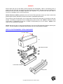
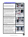
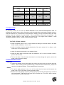
Table of Contents
Cover Page ………………………………………………...........…........... CP
TOC ……………………………………………………………….…........... TOC
Title Page/Contact Info…………………………………………..…........... 1
Warranty/Component Illustration……………………………….…........... 2
Packing Lists……………………………………………………...…........... 3-4
Environmental Conditions/Safety Precautions……………......…........... 5
Instructions For Use
Introduction……………………………………………….............…...........6
Safety Precautions…………………………………...................…........... 7
General Specifications & Operating Parameters…….........…........... 7
General Care & Cleaning………………………………….........…........... 8
Gel Plate Preparation…………………………………………….…...........8
Gel Plate (Cassette) Assembly…………………………...........…........... 8
Unit Assembly For Casting and Running Gels………………..…........... 9
Casting The Gel………………………………………................…........... 10-11
Gel and Buffer Volumes…………………………………...........…........... 11
Sample Loading…………………………………………………..…........... 11
Comb Options……………………………………………............…........... 12 -13
Cooling Option…………………………………………...............…........... 13
Starting/Ending The Run………………………………..............….......... 13-14
Troubleshooting…………………………………………………..…........... 14-15
Reagent Information…………………………………….............…........... 16
Replacement Parts……………………………………………….…........... 17
Chemical Compatibility Chart…………………………..............…........... 18
Notes………………………………………………………...........…........... 19
Copyright Galileo Bioscience™ 2004 – TOC
TWIN VERTICAL ELECTROPHESIS
SYSTEM
USER’S MANUAL
rev. 10/1/04
85-1010-WCS, 85-1010-NCS, 85-2010-WCS, 85-2010-NCS, 85-1614, AND 85-2020
WARNING
THESE UNITS ARE CAPABLE OF DELIVERING POTENTIALLY LETHAL VOLTAGE WHEN
CONNECTED TO A POWER SUPPLY AND ARE TO BE OPERATED ONLY BY QUALIFIED
TECHNICALLY TRAINED PERSONNEL.
PLEASE READ THE ENTIRE OPERATOR’S MANUAL THOROUGHLY BEFORE OPERATING THIS
UNIT.
UNITS COMPLY WITH THE STATUTORY CE SAFETY DIRECTIVES
Galileo Bioscience
P. O. Box 390566
Cambridge, MA 02139
Toll Free: 877-481-9175
Tel: 781-481-9175
Fax: 781-481-9214
www.galileobioscience.com
Copyright Galileo Bioscience™ 2004 – Page 1
WARRANTY
Please check that the unit has been received complete and undamaged. Refer to the Packing Lists on
pages 3 & 4 and check that all components and accessories are present. Be sure to save all packaging and
documents until you have thoroughly inspected your shipment, if you should find that your order is
incorrect or damaged, call for return instructions.
Galileo Bioscience (Galileo) guarantees that the Vertical Electrophoresis System you have received has
passed rigorous quality assurance protocols and meets its published specification.
This warranty is valid for 48 months, only if the product has been used and cared for according to this user
manual. No liability is accepted for loss or damage arising from incorrect use. Galileo’s liability is limited
to the repair or replacement of the unit or refund of the purchase price, at our option. Galileo is not
liable for any consequential damages.
Galileo reserves the right to alter the specifications of the Vertical Electrophoresis Systems without prior
notice. This will enable us to implement improvements as soon as they become available.
VERTICAL ELECTROPHORESIS SYSTEM COMPONENTS
To Power Supply
Lid
Upper Buffer Chamber
Lower Buffer Chamber
Casting Base
Copyright Galileo Bioscience™ 2004 – Page 2
PACKING LISTS
85-1010-WCS & 85-1010-NCS
(1)
User's Manual
(1)
Safety Lid with integral double insulated power cords (rated safe up to 1,000 volts) with
Retractable Sheathed Power Connectors
(1)
Upper Buffer Chamber with color coded electrodes and gold plated banana plugs
85-1010-WCS unit has a cooling core sealed with an alumina plate & "in and "out"
Hose Barb Fixtures for water circulation
(1)
Lower Buffer Chamber
(4)
Blank Glass Plates, 10cmW x 10cmL x 0.24cm thick
(2)
Notched Glass Plates, 10cmW x 10cmL x 0.24cm thick
(2)
Notched Alumina Plates, 10cmW x 10cmL x 0.10cm thick
(1)
Blocking Plate for running one gel
(4)
Side Spacers, 0.8mm thick
(2)
10 well Teflon® Comb, 0.8mm thick
(1)
Set (2) replacement gaskets for the upper buffer chamber
(1)
Casting Base
(1)
Set (2) replacement gaskets for the casting base
85-2010-WCS & 85-2010-NCS
(1)
User's Manual
(1)
Safety Lid with integral double insulated power cords (rated safe up to 1,000 volts) with
Retractable Sheathed Power Connectors
(1)
Upper Buffer Chamber with color coded electrodes, gold plated banana plugs
85-2010-WCS units has a cooling core sealed with an alumina plate & "in and "out"
Hose Barb Fixtures for water circulation
(1)
Lower Buffer Chamber
(4)
Blank Glass Plates, 20cmW x 10cmL x 0.32cm thick
(4)
Notched Glass Plates, 20cmW x 10cmL x 0.32cm thick
(1)
Blocking Plate for running one gel
(8)
Side Spacers, 0.8mm thick
(2)
15 well Teflon® Comb, 0.8mm thick
(2)
20 well Teflon Comb®, 0.8mm thick
(1)
Set (2) replacement gaskets for the upper buffer chamber
(1)
Casting Base
(1)
Set (2) replacement gaskets for the casting base
85-1614
Copyright Galileo Bioscience™ 2004 – Page 3
(1)
User's Manual
(1)
Safety Lid with integral double insulated power cords (rated safe up to 1,000 volts) with
Retractable Sheathed Power Connectors
(1)
Upper Buffer Chamber with color coded electrodes and gold plated banana plugs
85-1614 units have a cooling core sealed with an alumina plate & "in and "out"
Hose Barb Fixtures for water circulation
(1)
Lower Buffer Chamber
(4)
Blank Glass Plates, 16cmW x 14cmL x 0.32cm thick
(4)
Notched Glass Plates, 16cmW x 14cmL x 0.32cm thick
(1)
Blocking Plate for running one gel
(8)
Side Spacers, 1.5mm thick
(2)
15 well Teflon® Comb, 1.5mm thick
(2)
20 well Teflon® Comb, 1.5mm thick
(1)
Set (2) replacement gaskets for the upper buffer chamber
(1)
Casting Base
(1)
Set (2) replacement gaskets for the casting base
85-2020
(1)
User's Manual
(1)
Safety Lid with integral double insulated power cords (rated safe up to 1,000 volts) with
Retractable Sheathed Power Connectors
(1)
Upper Buffer Chamber with color coded electrodes and gold plated banana plugs
85-2020 units have a cooling core sealed with an alumina plate & "in and "out"
Hose Barb Fixtures for water circulation
(1)
Lower Buffer Chamber
(4)
Blank Glass Plates, 20cmW x 20cmL x 0.32cm thick
(4)
Notched Glass Plates, 20cmW x 20cmL x .032cm thick
(1)
Blocking Plate for running one gel
(8)
Side Spacers, 1.5mm thick
(2)
15 well Teflon Comb, 1.5mm thick
(2)
20 well Teflon Comb, 1.5mm thick
(1)
Set (2) replacement gaskets for the upper buffer chamber
(1)
Casting Base
(1)
Set (2) replacement gaskets for the casting base
Copyright Galileo Bioscience™ 2004 – Page 4
ENVIRONMENTAL CONDITIONS FOR USE
¾
This unit is intended for indoor use only
¾
This unit can be operated safely at an altitude of 2,000 m
¾
The normal operating temperature range is between 4ºC and 65ºC
¾
Maximum relative humidity 80% for temperatures up to 31ºC decreasing linearly to 50% relative
humidity at 40ºC
SAFETY PRECAUTIONS
Please read the User Manual carefully before using the Vertical Electrophoresis Unit. This manual contains
important operating and safety information. Our electrophoresis units are designed to perform flawlessly
for years in the most demanding laboratories. Please take the time to read the manual to ensure that you
understand the safety and operating instructions to ensure the successful use of the unit. Alterations
could cause serious injury to the user or the system.
Power to the unit is supplied by an external power supply. The power supply must meet safety standards
for IEC 1010-1 regulations and must be ground isolated and incorporate a no load detecting circuit.
Power is supplied to the gel through the lid of the system providing a safety interlock to the user. Users
should not attempt to operate this unit without the safety inter-locked lid in place.
∆
Always disconnect the unit from the power supply before removing the cover to avoid the risk of
personal shock.
∆
Running Conditions should not exceed the maximum operating voltage or current.
∆
Do not fill the Lower Buffer Chamber with running buffer above the maximum fill line.
∆
Always disconnect the unit from the power supply when you want to move the unit or add running
buffer.
∆
Use this apparatus only for its intended purpose as described in this manual. Do not use this
product if the power cords are damaged or if any of its surfaces are cracked.
Copyright Galileo Bioscience™ 2004 – Page 5
Reflection™ Twin Vertical
Series
INSTRUCTIONS FOR USE
INTRODUCTION
Thank you for your purchase of a Galileo Reflection™ Twin Vertical Gel Electrophoresis System!
Our vertical systems allow for fine resolution of protein or nucleic acid fragments on one or two
acrylamide gels (PAGE). PAGE separation offers the superior resolution necessary to separate native or
denatured proteins and nucleic acids in applications such as SSCP or dinucleotide repeat analysis using
western blotting and also for automated protein sequencing analysis.
All four models in the Galileo Reflection™ Twin Vertical Series incorporate inspired design features and
exceptional manufacturing methods that ensure dependable performance over years of continuous use.
A comprehensive offering of combs and accessories, plus the compatibility of the 85-1010-WCS & 851010-NCS with most commercially available pre-cast mini gels, ensures maximum system utility to
exceed the separation demands of most research laboratories.
¾
¾
¾
¾
¾
¾
¾
¾
¾
¾
¾
¾
¾
Outstanding Features Ensure Trouble-Free Use
Robust Acrylic Construction Stands up to Daily Usage without Breakage, Warping or Leakage
Rugged, Spring-Loaded Clamp Mechanism, Alignment Pins & Hollow Gaskets Guarantee Reliable
Leak-Proof Gel Installation
Precision Glass Plates Provide Exceptional Flatness and Finished Edges to Ensure Uniform
Separation
Casting Base Enables Casting Directly on the Upper Buffer Chamber Obviating Need to Move Gels
once Polymerized
Intelligent Design Results in Exceptional Resolution
Electrode Configuration Assures Uniform Field, Straight Lanes and Rapid Runs – Saving Time and
Improving Data Generation Rate
Proximal Upper Buffer Chamber Exploits Specific Heat of Aqueous Buffer to Provide Uniform
Temperature and No Smiling
Efficient Water Cooling System, Available on All Systems, Prevent Band Distortion
Optional Notched Alumina Plates available for the mini 10 cm x 10cm unit Enhance Heat
Dissipation
Wide Variety of Options Maximize Product Versatility
Devices Available For Four Gel Sizes, Including the wide mini 85-2010-WCS & 85-2010-WCS that
Accommodate 72 Samples, Supporting Most PAGE Applications.
Optional Additional Upper Buffer Chambers Allow for Simultaneous Use of the Twin Systems –
Improving Data Output Rate
Non-Cooled 10cm x 10cm & 20cm x 10cm Upper Buffer Chambers Available
Wide Selection of Combs, plus Glass and Blocking Plates Available for All Units
Units are Compatible with Pre-cast Acrylamide Gels from Most Manufacturers and Vertical Agarose
(VAGE) Separation.
Copyright Galileo Bioscience™ 2004 – Page 6
USING THE VERTICAL GEL ELECTROPHORESIS UNITS
SAFETY PRECAUTIONS
∆
READ all instructions before using the unit
∆
Always turn off power supply FIRST then disconnect the power cords. Always have electrophoresis
unit disconnected from their power supply before removing the safety cover.
∆
DO NOT exceed the maximum operating voltage or current (see TABLE A)
∆
DO NOT operate electrophoresis units in metal trays.
∆
Acrylamide is a volatile, cumulative neurotoxin and suspected carcinogen.
protective clothing and follow recommended handling and disposal procedures.
∆
Polymerized gels contain some unpolymerized monomer. Handle with gloves only.
∆
DO NOT fill the unit with running buffer above the maximum Fill Line
∆
DO NOT move the unit when it is running
∆
CAUTION: During electrophoresis very low quantities of various gases are produced at the
electrodes. The type of gas produced depends on the composition of the buffer employed. To
disperse these gases make sure that the unit is run in a well-ventilated area.
Wear effective
TABLE A: General Device Specifications/General Operating Parameters
85-1010-NCS
85-1010-WCS
10cmW x 10cmL
or
10cmW x 8cmL
170ml (non cooled
400ml (non cooled
slightly more)
slightly more)
400ml
600ml
~ 240ml
~ 450ml
~ 300ml
~ 800ml
Total Running Buffer
~ 450ml
~ 750 ml
~ 650ml
~ 1250ml
Total Buffer Capacity
Current (mAmps),
Constant
Maximum Voltage
(volts)
~ 450ml
~ 1100-1300 ml
~ 650ml
~ 1250ml
15-35mA/gel
30-45mA/gel
15-50mA/gel
15-75mA/gel
600V
600V
600V
600V
Time Requirements
30-90 minutes
30-90 minutes
60-120 minutes
60-180 minutes
24
72
48
50
Unit Model Number
Gel Size
Upper Buffer Chamber
Capacity
Lower Buffer Chamber
Capacity
Sample Capacity
85-2010-NCS
85-2010-WCS
20cmW x 10cmL
85-1614
16cmW x 14cmL
or
16cmW x 16cmL
Copyright Galileo Bioscience™ 2004 – Page 7
85-2020
20cmW x 20cmL
GENERAL CARE & CLEANING
WARNING !!
Acrylic is not resistant to aromatic or halogenated hydrocarbons, ketones or esters. Organic solvents
cause acrylic to “craze” or crack. Do not use ethanol or other organic solvents to clean your unit. Do
not autoclave, bake or microwave your unit.
∆
Before using, clean and dry unit with DISTILLED WATER ONLY; dry parts with clean tissues or air dry.
Use care when cleaning or drying the unit near the platinum wire. The connectors should be clean
and dry before usage or storage.
∆
Do not use abrasive creams or scourers.
∆
Do not use cleaning brushes in the electrode area
∆
A thorough rinse with distilled water is all that is generally required to clean the unit after use. A
mild detergent may also be used. Acrylic can also be exposed to a mild bleach solution (10:1). In
addition RNAse removal products are also safe for acrylic.
See Page 19 for Chemical Compatibility Chart
GEL PLATE PREPARATION
Clean the glass plates, spacers and combs in mild laboratory detergent. ∆ DO NOT use abrasive creams or
scourers. If a particularly clean finish is required (e.g. for silver-stained gels) glass plates can be soaked in
chromic acid overnight, rinsed with water, then wiped successively with ethanol, acetone then ethanol
again. ∆ DO NOT ALLOW organic solvents or chromic acid to come into contact with the acrylic
components of your vertical system.
Handle clean plates with gloved hands (remove any finger prints with acetone)
GEL PLATE (CASSETTE) ASSEMBLY
1. On a clean, level bench position the two side spacers flush with the edges of the blank glass plate
and overlay the notched plate.
Copyright Galileo Bioscience™ 2004 – Page 8
UNIT ASSEMBLY FOR CASTING AND RUNNING GELS
1.Turn Over the Casting Base so that the four acrylic
positioning squares are on the top.
2.Place the Upper Buffer Chamber on the Casting
Base. The precision-machined Upper Buffer
Chamber should fit over the four squares snugly.
3.Loosen the wing nuts and slide the clamp bars
outward. Please note the nylon alignment pins.
These pins assure that the glass plates are properly
placed over the Upper Buffer Chamber gasket, while
the acrylic squares on the casting base assure that
the glass is positioned evenly and at the proper
place for optimum sealing on the casting base
gaskets.
4.Place the gel plate assemblies (cassettes) with the
notched glass plate innermost against the gasket of
the Upper Buffer Chamber. The assemblies should
rest on the positioning squares of the Casting Base
and between the nylon alignment pins.
5.To clamp the assembly to the Upper Buffer Chamber
slide the clamp bars towards the middle. Tighten
the wing nuts until a seal is formed between the
gasket and the glass. The hollow gasket allows for a
superb seal without over-tightening the wing nuts.
Over-tightening may cause the glass to break.
6.If casting and running two gels, repeat steps 4 – 6
for the second gel plate assembly. If you desire to
run only one gel, secure the blocking plate to the
second side. Note: a combination of two gel
assemblies or one gel assembly and the Blocking
Plate are necessary to form the walls of the Upper
Buffer Chamber.
7.Lift the assembled Upper Buffer Chamber and turn
the Casting Base over. Turn the cams so that the
handle is pointing up and pull out. Place the Upper
Buffer Chamber on the gaskets. Note: A protective
plastic film is left on the gaskets for shipping. A
piece of clear tape has been fastened to the end of
the film to assist the user in removing it.
8.Insert the cam pins and simultaneously turn the
handles one half turn to tighten the assembly down
onto the gasket base. Once the Upper Buffer
Chamber assembly has been secured onto the
casting base an initial leak test using a small
amount of water is recommended – add 2ml-3ml of
water and let stand for 2 minutes. If no leakage is
visible, empty water and proceed with gel casting.
Copyright Galileo Bioscience™ 2004 – Page 9
CASTING THE GEL
To ensure reproducibility and uniform polyacrylamide cross-linking we recommend de-ionizing, de-gassing
and filtration of acrylamide gel solutions prior to use. Acrylamide solutions should be stored in a cool,
dark environment such as a refrigerator and allowed to reach room temperature prior to pouring. Avoid
exposure to heat and sunlight.
Polymerization conditions should be adjusted to effect polymerization within about 5-10 minutes. Test a
small volume in a vial prior to pouring the gel. As a rough guide, 100ml of degassed 6% acrylamide gel will
set in about 5 minutes at room temperature when gently mixed with 450µl of freshly prepared 10% (w/v)
Ammonium persulphate plus 200µl TEMED. The setting time increases to about 10 minutes if the TEMED
volume is reduced to 100µl and to approximately 15 minutes with 75µl. The amount of catalysts may need
to be reduced under warm conditions. Do not pour under direct sunlight.
1. Prepare the appropriate volume of acrylamide gel solution using Table B below as a guide. These
volumes have been calculated using the glass and spacers provided by Galileo, and subtracting the
volume of the spacers and the notch. The volumes are approximate.
TABLE B: Approximate Gel Solution Volumes For Various Cassette Configurations
Unit
85-1010
Plate Width
10cm
10cm
10cm
10cm
Plate Length
10cm
10cm
8cm
8cm
Spacer Thickness
0.8mm
1.5mm
0.8mm
1.5mm
Gel Volume
7.5ml
15ml
6ml
12ml
85-2010
20cm
20cm
10cm
10cm
0.8mm
1.5mm
15ml
30ml
85-1614
16cm
16cm
16cm
16cm
14cm
14cm
16cm
16cm
0.8mm
1.5mm
0.8mm
1.5mm
13.5ml
27ml
15ml
30 ml
85-2020
20cm
20cm
20cm
20cm
0.8mm
1.5mm
24.6ml
49.1ml
2. Run the acrylamide gel solution mix slowly down the inside edge of the gel cassette. Avoid
aeration. Place the comb in the gel plate assembly.
a. If a stacking gel is to be used, carefully overlay the gel solution to a depth of 3-5mm with
1x gel buffer or water-saturated butanol. Following polymerization of the separating gel,
pour off the overlay layer (rinse off butanol with electrophoresis gel buffer) and pour a
stacking gel if required. Insert the comb ensuring bubbles are not trapped around comb
teeth. Once the stacking gel has polymerized use the gel immediately or store wrapped in
a damp paper towel and plastic film at 4 Cº. Wait a minimum of 15 minutes for the gel to
polymerize. Repeat process as required.
3. Release the cams and pull away from the Upper Buffer Chamber and gels. Wash off any residual
acrylamide. Place the Upper Buffer Chamber into the Lower Buffer Chamber. Stainless Steel pins
are located on the lower sides of the Upper Buffer Chamber that slide into the precision machined
clear sides of the Lower Buffer Chamber to set it in place.
Copyright Galileo Bioscience™ 2004 – Page 10
4. Add the appropriate volume of running buffer to the upper buffer chamber (Table A gives
approximate volumes), making sure the running buffer is 3 mm below the top of the blank glass,
ensuring sufficient contact with the top of the gel surface. Be sure that the running buffer is not
leaking from the upper buffer chamber to the lower buffer chamber. If buffer is leaking you will
need to drain the UBC and reset the gel cassettes.
NOTE: When running only one gel a blocking plate is required on the other side of the unit to
retain the top buffer level
GEL AND BUFFER VOLUMES
Some guidelines for general operating conditions are given in Table A, but conditions vary according to the
number of gels, their composition, length, and cross sectional area. The current requirement will
increase in proportion to the number of gels or gel thickness providing that the voltage is not limiting, e.g.
2 gels require twice the current of 1, but the same voltage. Longer gels require proportionally higher
voltages. By increasing the gel concentration the electrical resistance is increased and the rate of
migration decreases. Higher voltages can be applied but be careful not to overheat the gel. The
conductivity of non-dissociating buffer systems gels vary enormously and conditions must be determined
empirically.
The run conditions are to be taken as a guideline only and apply to SDS Tris-glycine gels. If the plates
become hot increase the water flow rates within the recommended limits or reduce the power settings.
SAMPLE LOADING
¾
¾
¾
¾
¾
¾
¾
If a native gel is being used, pre-electrophorese the gel for 15-40 minutes prior to loading
samples. SDS gels do not need this step.
Centrifuge samples at 12,000 x g for 5 minutes. If this step is omitted samples may streak during
electrophoresis.
Carefully remove the sample comb and immediately flush the wells with electrophoresis buffer
using a syringe.
Load the samples using a gel loading pipette tip. See TABLE D on the next page for approximate
well volumes, etc. If possible avoid taking liquid from the pellet area at the bottom of the tube.
During sample loading the pipette tip should be 1-2 mm above the bottom of the well to minimize
dilution of the sample and to keep the sample as a tight layer.
Fill unused wells with the equivalent volume of sample buffer to maintain uniform electrical
resistance across the gel.
Add buffer to the lower buffer chamber to approximately 2-3 mm above the base of the gel using
the Fill Line as a guide. The bottom end of the gel assembly should be in contact with the running
buffer.
Set the safety lid onto the unit so that the power cords are connected in the proper position (red
to red, black to black)
Copyright Galileo Bioscience™ 2004 – Page 11
TABLES C1, C2, C3 & C4: Comb Options
Table C1 - MODEL 85-1010-NCS or 85-1010-WCS Combs
Number
of
Teeth
Thickness
of Tooth (mm)
Width
of Teeth
(mm)
EST Well
Volume (ul)
85-1010-C6-0.8
6
0.8
11.1
142
85-1010-C6-1.5
6
1.5
11.1
266
85-1010-C8-0.8
8
0.8
7.7
99
85-1010-C8-1.5
8
1.5
7.7
185
85-1010-CMT9-0.8
9
0.8
6.6
84
85-1010-CMT9-1.5
9
1.5
6.6
160
85-1010-C10-0.8
10
0.8
5.7
73
85-1010-C10-1.5
10
1.5
5.7
136
85-1010-C12-0.8
12
0.8
4.3
55
85-1010-C12-1.5
12
1.5
4.3
103
85-1010-C15-0.8
15
0.8
3.0
38
85-1010-C15-1.5
15
1.5
3.0
72
Thickness
of Tooth (mm)
Width
of Teeth
(mm)
EST Well
Volume (ul)
Catalog
Number
Table C2 - MODEL 85-1614 Combs
Number
Catalog
of
Teeth
Number
85-1614-C10-0.8
10
0.8
10.4
183
85-1614-C10-1.5
10
1.5
10.4
343
85-1614-C15-0.8
15
0.8
6.1
107
EPH-1614V-C15-1.5
15
1.5
6.1
201
EPH-1614V-C20-0.8
20
0.8
3.9
69
EPH-1614V-C20-1.5
20
1.5
3.9
129
EPH-1614V-C24-0.8
24
0.8
2.9
51
EPH-1614V-C24-1.5
24
1.5
2.9
96
EPH-1614V-CPREP
2
1.5
119.7/4.7
3630/152
Table C3 - MODEL 85-2010-NCS or 85-2010-WCS Combs
Number
of Teeth
Thickness
of Tooth (mm)
Width
of Teeth
(mm)
EST Well
Volume (ul)
85-2010-C10-0.8
10
0.8
13.6
239
85-2010-C10-1.5
10
1.5
13.6
449
85-2010-C15-0.8
15
0.8
8.2
144
85-2010-C15-1.5
15
1.5
8.2
271
85-2010-CMT18-0.8
18
0.8
6.5
78
85-2010-CMT18-1.5
18
1.5
6.5
156
85-2010-C20-0.8
20
0.8
5.5
97
85-2010-C20-1.5
20
1.5
5.5
182
85-2010-C25-0.8
25
0.8
3.9
69
Catalog
Number
85-2010-C25-1.5
25
1.5
3.9
129
85-2010-CMT36-0.8
36
0.8
2.7
32
85-2010-CMT36-1.5
36
1.5
2.7
64
Copyright Galileo Bioscience™ 2004 – Page 12
Table C4 - MODEL 85-2020 Combs
Number
of
Catalog
Teeth
Number
Thickness
of Tooth (mm)
Width
of Teeth
(mm)
EST Well
Volume (ul)
85-2020-C10-0.8
10
0.8
13.6
239
85-2020-C10-1.5
10
1.5
13.6
449
85-2020-C15-0.8
15
0.8
8.2
144
85-2020-C15-1.5
15
1.5
8.2
271
85-2020-C20-0.8
20
0.8
5.5
97
85-2020-C20-1.5
20
1.5
5.5
182
85-2020-C25-0.8
25
0.8
3.9
69
85-2020-C25-1.5
25
1.5
3.9
129
85-2020-CPREP
2
1.5
148.1/4.7
4885/155
COOLING OPTION
As previously noted, all four sizes of Galileo Reflection™ Twin Vertical Electrophoresis Units are
available with optional water-cooling. Sometimes cooling is needed when running gels at higher current or
when the bioactivity of an enzyme has to be preserved. Heating of the gel can cause smiling and other
problems with the resolution of protein bands. This is particularly pronounced on larger gels. We
recommend running coolant or water through the cooling core in the upper buffer chamber. When
ramping up voltage or current, consider at least tap water cooling.
TO UTILIZE OPTIONAL COOLING:
¾
Attach a separate piece of 3/8” ID clear flexible lab tubing to each hose barb on the upper
buffer chamber marked as “in” and “out”
¾
Attach the tubing from the cathode (black) side of the unit, marked “in” to either a coldwater tap or a re-circulator/chiller.
¾
Water flow should not exceed 2 L per minute at 30 psi.
¾
Attach the drain tube on the anode (red) side marked as “out” to the re-circulator chiller or
put into the sink drain.
¾
Turn on the water. Once the water has started to circulate through the system, connect the
power cords to the power supply
STARTING/ENDING THE RUN
STARTING:
¾ Connect the chamber to the power supply and connect the power supply to the main electrical
source. Turn all settings to zero before turning on the main source of electricity. Adjust the
controls to the desired settings. Follow manufacturer’s instructions.
ENDING:
¾ Turn power supply settings to zero, turn off the main electrical source and disconnect the
power cords. Turn off the water (if using optional cooling).
¾ Remove the lid by pushing on the acrylic alignment pins protruding through the top of the lid
with your thumbs. Slide and lift the upper buffer chamber out of the lower buffer chamber
and drain buffer chambers separately.
Copyright Galileo Bioscience™ 2004 – Page 13
¾
¾
¾
Loosen wing nuts and slide clamp bars outward to remove gel cassettes. It is not necessary to
remove the clamp bars from the upper buffer chamber to remove the gel cassette.
After the gel cassette(s) has been removed the gel(s) are ready for staining and blotting.
Separate the plates with a strong broad blade. When using notched glass plates DO NOT pry
them apart at the notches. Spread the load over a wide area.
Rinse the chambers with distilled water then dry the electrode connectors with tissue. Ensure
that the connectors are clean and dry before usage or storage.
TROUBLESHOOTING
Many factors may affect the quality of vertical gel preparations. For example, preparation of gel and
sample buffers; gel casting and tank assembly and/or run conditions. Reading and following the
instructions in this operating manual can solve most problems. Below we list some of those most
commonly experienced problems along with suggestions for solving them.
Problem: Acrylamide Solution Leaks During Casting
¾ Ensure that the sealing surfaces of the glass plates and spacers are clean
¾ Ensure that each plate is free of chips
¾ Ensure that the wing-knobs on the upper buffer chamber are tightened (use care not to overtighten)
¾ Ensure that the glass plates and spacers have been set in place using the positioning squares on
the “Flip-Side” of the Gel Casting Base.
¾ Ensure that the Cams in the Casting Base have been turned equally to tighten down the Upper
Buffer Chamber on the gaskets
Problem: Bubbles Do Not Appear on the Electrodes
¾ Check to see if the Power Supply is operating properly
Problem: Gels Fail to Polymerize
¾ May be caused by low temperatures, oxygen, insufficient/degraded catalyst, or low acrylamide
concentrations
Problem: Run Takes Longer Than Usual
¾ Buffers may be too concentrated or at the wrong pH. Gel concentration may be too high. Check
Buffer Recipe and try again. See if voltage produced by the current you are running at is the
same. If it differs significantly, your buffer may not have been made up correctly.
¾ Upper Buffer Chamber may be leaking buffer: Make sure the gel assembly is seated firmly against
the gasket. Remove gasket, wash in warm water to remove excess salts, and place the gasket
back in the groove.
¾ Running at too low a current: Use running conditions given in this manual. When running at
constant current, the current value listed is per gel.
Problem: Running Too Fast
¾ Check buffer recipe; remake and try again. If voltage is lower than usual when running at
constant current, the buffer is probably too dilute.
Copyright Galileo Bioscience™ 2004 – Page 14
¾
Voltage or current may be set too high: turn down current setting.
Problem: “Smiling” of Dye Front
¾ The center of the gel is running hotter than at the edges: use coolant or cold tap water in cooling
core and/or turn down current setting.
Problem: Vertical Streaking
¾ Excessive sample or particles in the sample: either dilute sample or reduce voltage. Centrifuge
samples to remove particulate contamination.
¾ Sample has precipitated: Centrifuge sample before adding sample buffer or use a lower
% acrylamide gel.
Problem: Bands Spread Laterally
¾ Diffusion of sample: Make sure the samples are loaded quickly and the power is applied as soon as
possible after loading.
¾ Diffusion of sample during the run in the stacking gel: Increase % of stacking gel or increase
current by 25% when stacking.
¾ Lower ionic strength of the sample: Match the ionic strength of the sample with that of the gel.
Problem: Bands are Narrower than the Sample Wells
¾ Ionic strength of the sample is higher than that of the gel: De-salt the sample or use sample
buffer of the same strength as the gel.
Problem: Distorted Sample Wells
¾ Incomplete polymerization produces poorly defined wells: De-gas gel solution prior to casting and
increase APS and TEMED concentrations. The comb can be wiped with TEMED just prior to casting
to improve polymerization.
¾ Salt concentration is too high in the sample: Dialyze sample or use desalting column.
Problem: Resolving gel is uneven at the top
¾ Overlay gel carefully using water saturated n-butanol and make sure casting stand is level.
Problem: Poorly Resolved Bands
¾ May be caused by too much sample for well width or gel thickness: Dilute sample. Lower volumes
generally give better resolution.
¾ Excessively high voltages cause fast run times, but poor resolution. Sample may have degraded.
Problem: Frowning of Outside Lanes
¾ Leakage of Buffer along the sides or along the spacers inside the gel assembly: Do not move
spacers after polymerization and make sure that the gasket is seated firmly against the glass.
Problem: Double Bands – “Doublets”
¾ Due to re-oxidation or insufficient reduction of the sample: If using a reducing agent, prepare
fresh sample buffer every 30 days. Increase the concentration of 2-mercaptoethanol or
dithiothreitol in the sample.
Problem: Fewer Bands than Expected with Heavy Band at Dye Front
¾ Caused by more than one band migrating to the dye front: increase total monomer concentration
(%T).
¾ Sample may have degraded due to incorrect storage and/or contamination.
Copyright Galileo Bioscience™ 2004 – Page 15
REAGENT INFORMATION
RUNNING BUFFER
TGS
Tris 3.0285g/L
Glycine 14.4g/L
SDS 1.0g/L
pH 8.3 (Laemmli, 1970)
Q.s to 1L
Note: For Native Protein Electrophoresis do not add SDS
Table D1
Sample Buffer
2X Concentration
Final Concentration
Stock
With Sample*
/L
/10mL
2%
SDS
20g
0.2
1%
10%
BME
10mL
0.1
5%
25mM
Tris
6.057g
0.0606g
125mM
30%
Glycerol
300mL
3mL
15%
0.002%
Bromo Phenol Blue
.02g
.0002g
0.001%
* add sample buffer 1:1 with sample solution
Caution: 2X Sample Buffer containing 2-mercaptoethanol should be prepared in a fume hood.
0.2M (final concentration) Dithiothreitol (DTT) may be used in place of 2-mercaptoethanol.
DDT should be added before use and made fresh
ACRYLAMIDE SOLUTION
Stock acrylamide solution for D2 = 29.2g Acrylamide and .8 bis-Acrylamide, q.s. 100mL H20
TABLE D2 - Gel Preparation(SDS-Page continuous buffer system)
% Acrylamide*
Stock Solution
20.0
15.0
12.5
10.0
5.0
Acrylamide-Bisacrylamide (30:08)
20.0
15.0
12.5
10.0
5.0
0.5 M Sodium Phosphate Buffer pH 7.2
6.0
6.0
6.0
6.0
6.0
10% (w/v) SDS
0.3
0.3
0.3
0.3
0.3
Water
2.2
7.2
9.7
12.2
17.2
1.5% (w/v) APS
1.5
1.5
1.5
1.5
1.5
0.015
0.015
0.015
TEMED
* The columns represent volumes (ml) of stock solutions required to prepare 30ml of gel mixture.
Copyright Galileo Bioscience™ 2004 – Page 16
0.015 0.015
REPLACEMENT PARTS
DESCRIPTION
85-1010
85-2010
85-1614
85-2020
Power Supply Cords (Retractable Sheath)
RPC
RPC
RPC
RPC
Power Supply Cords (Non-Retractable Sheath)
NRPC
NRPC
NRPC
NRPC
UBC Replacements Gaskets
85-1010-GSK
85-2010-GSK
85-1614-GSK
85-2020-GSK
Casting Base Replacement Gaskets
85-1010-CBGK
85-2010-CBGK
85-1614-CBGK
85-2020-CBGK
Blank Glass Plate, 3/32" (2.3mm)
85-1010-10BG
85-2010-10BG
85-1614-14BG
85-2020-20BG
85-2010-10NG
85-1614-14NG
85-2020-20NG
85-1614-BPL
85-2020-BPL
Blank Glass Plate, 1/8" (3.0mm)
Notched Glass Plate, 3/32" (2.3mm)
85-1010-10NG
Notched Glass Plate, 1/8" (3.0mm)
Notched Alumina Plate, 1.0mm
85-1010-10NA
Blocking Plate for Running One Gel
85-1010-BPL
85-2010-BPL
Spacers, 0.8mm
85-1010-SP-0.8
85-2010-SP-0.8 85-1614-SP-0.8
85-2020-SP-0.8
Spacers, 1.5mm
85-1010-SP-1.5
85-2010-SP-1.5 85-1614-SP-1.5
85-2020-SP-1.5
Clamp Assemblies
85-1010-CL
85-2010-CL
85-1614-CL
85-2020-CL
Wing Knobs(4)
85-WKNB
85-WKNB
85-WKNB
85-WKNB
Spring Pegs (2)
85-PEGS
85-PEGS
85-PEGS
85-PEGS
Positioning Pegs
85-PP
85-PP
85-PP
85-PP
Positioning Peg Gasket
85-PP-GK
85-PP-GK
85-PP-GK
85-PP-GK
Copyright Galileo Bioscience™ 2004 – Page 17
The following is a chemical compatibility chart for the care of acrylic. Acrylic is compatible with most
solvents and solutions found in a biochemical laboratory, but some solvents can cause damage. The list
does not include all possible chemical compatibilities and/or safe compounds.
R = RESISTANT
LR = LIMITED RESISTANCE
N = NOT RESISTANT
LISTED BY CODE - ALL CHEMICALS IN THE FIRST COLUMN ARE SAFE TO USE
Chemical
Code
RESISTANT
Acetic Acid (5%)
Ammonia
Ammonium Chloride (saturated)
Ammonium Hydroxide (10%)
Ammonium Hydroxide (concentrate)
Battery Acid
Calcium Chloride (saturated)
Calcium Hypochlorite
Citric Acid (20%)
Cottonseed Oil (edible)
Detergent Solution (Heavy Duty)
Diesel Oil
2-Ethylhexyl Sebacate
Ethylene Glycol
Formaldehyde (40%)
Glycerine
Heptane
Hexane (commercial Grade)
Hydrochloric Acid (10%)
Hydrochloric Acid concentrate
Hydrogen peroxide ( up to 40%)
Hydroxide (10%)
Isooctane
Kerosene (no. 2 fuel oil)
Mineral Oil (white)
Naphtha (VM&P)
Nitric Acid (up to 20%)
Oleic Acid
Olive Oil
Soap Solution (Ivory)
Sodium Carbonate
Sodium Chloride
Sodium Hydroxide
Sodium Hypochlorite
Sulfuric Acid (up tp 30%)
Turpentine
Water (distilled)
R
R
R
R
R
R
R
R
R
R
R
R
R
R
R
R
R
R
R
R
R
R
R
R
R
R
R
R
R
R
R
R
R
R
R
R
R
Chemical
LIMITED RESISTANCE
Code
Acetic Anhydride
Chromic Acid (up to 40%)
Dioctyl Phthalate
Ethyl Alcohol (up to 30%)
Gasoline, regular, leaded
Isopropyl Alcohol (up to 50%)
Methyl Alcohol (up to 15%)
Nitric Acid (20% - 70%)
LR
LR
LR
LR
LR
LR
LR
LR
NOT RESISTANT
Acetic Acid (Glacial)
Acetone
Aniline
Benzene
Butyl Acetate
Carbon Tetrachloride
Chromic Acid (over 40%)
Chloroform
Diethyl Ether
Dimethyl Formamide
Ethyl Acetate
Ethyl Alcohol (95%)
Ethylene Dichloride
Hydrofluoric AcId (40%)
Hydrogen peroxide (over 40%)
Lacquer Thinner
Methyl Alcohol (over 15%)
Methylene Chloride
Methyl Ethyl Ketone (MEK)
Nitric Acid concentrate
Phenol 5% solution
Sulfuric Acid concentrate
Toluene
Trichloroethylene
Xylene
N
N
N
N
N
N
N
N
N
N
N
N
N
N
N
N
N
N
N
N
N
N
N
N
N
Copyright Galileo Bioscience™ 2004 – Page 18
NOTES
Copyright Galileo Bioscience™ 2004 – Page 19


![KeyView [4823353_1.wpd]](http://vs1.manualzilla.com/store/data/005667242_1-589c8deb81b55e7c0d34a0d078158765-150x150.png)