1
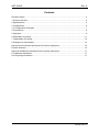
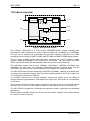
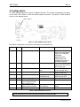
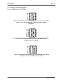
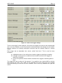
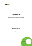
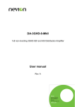
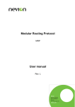
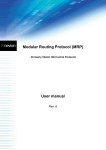
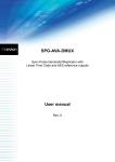
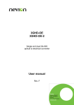
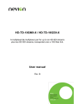
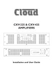
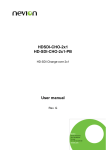
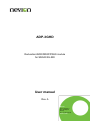
ADP-3GHD Redundant ADD/DROP/PASS module for SD/HD/3G-SDI User manual Rev. A Nevion Nordre Kullerød 1 3241 Sandefjord Norway Tel: +47 33 48 99 99 nevion.com ADP-3GHD Rev. A Nevion Support Nevion Europe Nevion USA P.O. Box 1020 3204 Sandefjord, Norway Support phone 1: +47 33 48 99 97 Support phone 2: +47 90 60 99 99 1600 Emerson Avenue Oxnard, CA 93033, USA Toll free North America: (866) 515-0811 Outside North America: +1 (805) 247-8560 E-mail: [email protected] See http://www.nevion.com/support/ for service hours for customer support globally. Revision history Current revision of this document is the uppermost in the table below. Rev. Repl. Date Sign A 0 2015-05-11 MB 0 - 2011-10-19 AJM Change description Cover page update; DoC removed; no changes to content Initial revision. nevion.com | 2 ADP-3GHD Rev. A Contents Revision history ..................................................................................................................... 2 1 Product overview ................................................................................................................ 4 2 Specifications ..................................................................................................................... 5 3 Configuration ...................................................................................................................... 6 3.1 Configuration Examples................................................................................................... 7 4 Connections ....................................................................................................................... 8 5 Operation ........................................................................................................................... 9 6 Redundant ring setup ........................................................................................................11 7 Independent ring setup ......................................................................................................12 8 Change over functionality ..................................................................................................13 General environmental requirements for Nevion equipment .................................................15 Product Warranty .................................................................................................................16 Appendix A Materials declaration and recycling information .................................................17 A.1 Materials declaration ......................................................................................................17 A.2 Recycling information .....................................................................................................17 nevion.com | 3 ADP-3GHD Rev. A 1 Product overview IN1 Signal integrity & Reclocker Switch Reclocker OUT1 PASS/ADD DROP1 Change Over ADD DROP2 DROP/MUTE Switch IN2 Signal integrity & Reclocker Reclocker OUT2 PASS/ADD Figure 1- ADP-3G block diagram The Flashlink ADP-3GHD is a multi bit-rate ADD/DROP/PASS module providing high performance media distribution for various signal formats from 19.4Mbps up to 2970Mbps. The unit can be operated as a redundant or dual ADP amplifier configured to do cable equalizing and reclocking of SMPTE 424M, SMPTE 292M and SMPTE 259M signal formats. The four inputs typically provide automatic cable equalizing for up to 70 meters of cable (Belden 1694A at 2970Mbps), with reclockers on all outputs. The ADP-3GHD will detect 3GHD, HD and SD rates and automatically switch to the correct output slew-rate. The reclockers support the bit-rates 270Mbps, 1483.5Mbps, 1485Mbps 2967Mbps and 2970Mbps. For other rates, the reclockers automatically switch to bypass mode, and the ADP-3GHD will work as a non-reclocking distribution amplifier with cable equalizers. The ADP-3GHD also supports reclocking of DVB-ASI at 270Mbps, enabling all possible rates including empty transport streams with only K28.5 padding packets. All of the outputs are non-inverting and suitable for DVB-ASI. In redundant operation the included intelligent change-over feature gives the ability to change between inputs based on input signal loss, loss of lock, EDH errors or a combination of the above. There is also included a passive bypass function from both inputs to non-inverted outputs with less than 15 m loss of cable length (enables full redundancy in case of mains failure). The ADP-3GHD is designed for all distribution purposes in studio, duplication and broadcast applications. Please observe that ADP-3GHD can not be used with N-Box, Flashlink one module desktop box, due to mechanical issues. nevion.com | 4 ADP-3GHD Rev. A 2 Specifications Electrical Outputs Connectors Output Return loss Output signal level Output signal rise / fall time 20% - 80% Amplitude overshoot Polarity Output timing jitter Output alignment jitter Electrical Inputs Connectors Input Cable Eq. @270Mbps Input Cable Eq. @1485Mbps Input Cable Eq. @2970Mbps Input Return loss Jitter tolerance Features Reclocking: Supported clock rates: Input equalizers: Supported standards SMPTE: 75 Ohm BNC - < -15dB, 5MHz -1.5GHz - < -10dB, 1.5GHz - 3GHz 800mV +/- 10% - SD limit: [0.4ns – 1.5ns]; <0.5ns rise/fall var. - HD limit: < 270ps, <100ps rise/fall var. - 3G HD limit: <135ps, <50ps rise/fall var. <10% - All outputs non-inverting - SD: <0.2 UI - HD: <1 UI - 3G HD: <1UI - SD: <0.15 UI - HD: <0.15 UI - 3G HD: <0.2UI 75 Ohm BNC >300m w/Belden 1694A, with BER < 10E-12 >100m w/Belden 1694A, with BER < 10E-12 >70m w/Belden 1694A, with BER < 10E-12 - < -15dB, 5MHz -1.5GHz - < -10dB, 1.5GHz - 3GHz - SD limit: - 10Hz-1kHz: >1 UI - 10kHz – 5MHz: >0.2 UI - HD limit: - 10Hz-100kHz: >1 UI - 100kHz–10MHz: >0.2 UI - 3G HD limit: - 10Hz-100kHz: >2 UI - 100kHz–10MHz: >0.3 UI Automatic SD/ HD detection Automatic output slew rate adjustment according to SMPTE 259M and SMPTE 292M/ SMPTE 424M 270, 1483.5, 1485, 2967, 2970Mbps Eq. bypass for non-video formats or low bit rates DVB-ASI: SMPTE 424M, SMPTE 292M, SMPTE 259M, SMPTE 305M, SMPTE 310M EN50083-9 (on non-inverting outputs) General DC power consumption: +5V / < 4.5W nevion.com | 5 ADP-3GHD Rev. A 3 Configuration The ADP-3GHD supports a number of different formats. The correct configuration can either be set with a DIP switch or with the GYDA system controller. The layout of ADP-3GHD is shown in the drawing below. DIP switches Figure 2 - ADP-3GHD module layout DIP switch configuration must be set according to the table below: Switch # 1 Label Function DIP=OFF Function DIP=ON RED Redundant ring 2 R1 3 R1 4 R2 5 R2 6 7 RCL EQ 8 OVR Independent rings Comment Card can work on either two independent rings or one ring with redundant paths/directions. Redundant mode implies CHO function on DROP outputs. Pass primary ring Add to primary ring Chooses which signal goes to the OUT port of the primary ring Drop from primary ring No drop from primary Enable DROP output ring for the primary ring. Pass secondary ring Add to secondary ring Only in use when switch #1 set OFF Drop from secondary ring No drop from Only in use when secondary ring switch #1 set OFF Reclocker Bypass Reclocker ON Reclocker mode Cable equalizer Bypass Cable Equalizer ON Equalizer mode (Loss of signal will not work on this mode) Module controlled by Module controlled by Select GYDA config. Gyda system controller DIP switches Mode Table 1: ADP-3GHD DIP switches All DIP switches are off when pointing towards the release handle. nevion.com | 6 ADP-3GHD Rev. A 3.1 Configuration Examples Typical configurations for ADP-3GHD: Figure 3 - Independent mode. Add to ring 1. Pass and drop ring 2. ADD1 to OUT 1. IN2 to OUT2 and DROP 2. With equalization, without reclocking. Figure 4 - Independent mode. Add to ring 1. Pass and drop ring 2. ADD1 to OUT 1. IN2 to OUT2 and DROP 2. Transparent mode without equalization and reclocking. Figur 1 Figure 5 - Independent mode, pass ring 1, pass and drop ring 2. IN1 to OUT1, IN2 to OUT2 and DROP 2. DROP 1 muted. nevion.com | 7 ADP-3GHD Rev. A 4 Connections The ADP-3GHD has two backplane options, DA-3GHD-2x4-C3 and DA-3GHD-2x4-C4. The connector placement of the two are equal, but the –C4 backplanes features passive byass between IN1 and O1A, and IN2 and O2A. This module is mounted at the rear of the subrack. Backplane names Redundant mode Dual mode IN1 IN1 IN1 O1A OUT1 OUT1 O1B DROP DROP1 ___ O1A ADD ADD1 IN2 IN2 IN2 O2A OUT2 OUT2 O2B DROP DROP2 ___ O2A Not in use ADD2 Figure 6 - Backplane connection view and signal mapping table Unused inputs and outputs should be terminated with 75 ohm to meet the specifications. nevion.com | 8 ADP-3GHD Rev. A 5 Operation The status of the module can be easily monitored visually by the LEDs at the front of the module. The LEDs are visible through the front panel as shown in 11 below. Status LOL & LOS 1 LOL & LOS 2 Main/Bypass Figure 7 - indicator overview (Text not printed on the front panel). The functions of the different LEDs are described in table below. Diode \ state Red LED Yellow LED Status Module is faulty LOL & LOS 1 No Reclocker (Input 1) Lock & Loss Of Signal LOL & LOS 2 No Reclocker (Input 2) Lock & Loss Of Signal Main/Bypass No stable input No Reclocker lock & Signal present Green LED Module is OK Module has power Reclocker in lock & Signal present No Reclocker lock & Signal present Reclocker in lock & Signal present Bypass selected by CHO Main selected by CHO No light Module has no power Not in redundant mode Table 2. LED status description nevion.com | 9 ADP-3GHD Rev. A GPI name Function (setup1/ (setup1/ setup2) setup2) Status General error status for the module. LOS DROP1 DROP2 Reset Set Ground Loss of signal or lock at main input Signal present on Drop 1 Signal present on Drop 2 Reset selected input to main Set selected input to standby Not used 0 volt pin Pin # Mode Direction Electrical Maximums for GPI outputs: Output Pin 1 Inverted Open Collector (open is alarm) Pin 2 Open Collector Output Pin 3 Open Collector Output Pin 4 Open Collector Output Pin 5 TTL, 0V = active level Pin 6 TTL, 0V = active level Pin 7 Pin 8 0V. Max current: 100mA Max voltage: 30V Max power: 200mW Input Input Table 3 - Description of GPI interface Figure 8 - GPI Interface nevion.com | 10 ADP-3GHD Rev. A 6 Redundant ring setup Signal integrity & Reclocker IN1 Switch Reclocker OUT1 PASS/ADD DROP1 Change Over ADD DROP2 DROP/MUTE Switch Signal integrity & Reclocker IN2 Reclocker OUT2 PASS/ADD Figure 9 - Redundant block diagram When the card is set up for a single ring with redundancy, the basic functionality is as follows: Mode DROP1 DROP2 OUT1 OUT2 ADD Muted Muted ADD1 ADD1 ADD+DROP Best of IN1 and IN2 Best of IN1 and IN2 ADD1 ADD1 PASS Muted Muted IN1 IN2 PASS+DROP Best of IN1 and IN2 Best of IN1 and IN2 IN1 IN2 Table 4 – Redundant ring modes nevion.com | 11 ADP-3GHD Rev. A 7 Independent ring setup Signal integrity & Reclocker IN1 ADD1 Switch Reclocker OUT1 PASS/ADD Switch DROP1 DROP/MUTE Signal integrity & Reclocker IN2 ADD2 Switch Reclocker OUT2 PASS/ADD Switch DROP2 DROP/MUTE Figure 10 - Independent block diagram When the card is set up for dual rings without redundancy, the basic functionality is as follows: Ring 1 Mode DROP1 OUT1 ADD Muted ADD1 ADD+DROP IN1 ADD1 PASS Muted IN1 PASS+DROP IN1 IN1 Table 5 – Ring 1 operating modes Ring 2 Mode DROP2 OUT2 ADD Muted ADD2 ADD+DROP IN2 ADD2 PASS Muted IN2 PASS+DROP IN2 IN2 Table 6 - Ring 2 operating modes nevion.com | 12 ADP-3GHD Rev. A 8 Change over functionality The change over functionality is only used when the card is set up for a redundant ring. The card has a number of signal integrity analyzers and something called "triggers". A trigger is another way of controlling the change-over functionality. The regular change-over configuration is used for setting latch on/off, EQ or RCL control etc. In addition, the signal integrity analyzers can be used to control the decision of which signal to use on the DROP output. Thus, the trigger is a link from the analyzer to the change-over. ADP-3GHD has four video analyzers. Figure 11 - Video analyzer settings Figure 9 shows the controls for these. The two inputs each have their analyzers, plus an extra "Stream 2" analyzer that is used when SMPTE 425M Level B mapping is used. These errors can be counted (or ignored) based on the settings in the configuration view: EDH VSTD No EDH packets (SD only) SMPTE 352 packets do not correspond to detected video standard (SD/HD only) Not supported for 3G. FFCRC Full Field CRC (SD only) APCRC Active Picture CRC (SD only) LOCK Analyzer chip is not locked to a bit stream (or stream 2 not present, for "Stream 2" analyzer) CCS Chroma channel ancillary data check sum error YCS Luma channel ancillary data check sum error CCRC Chroma channel video data check sum error YCRC Luma channel video data check sum error LNUM Line number error SAV Start of active video flags missing or misplaced EAV End of active video flags missing or misplaced Errors are checked once per video field (LOCK errors are counted every 20ms when no video is present). If an error occurs, it is checked against the bit mask, and if selected for counting increments the error counter. An SNMP tool is recommended for tracking error counts over time, with selectable limits on error rate and max count before generating a warning. The triggers are using the same information (and therefore have the same bit names as the analyzers), but have separate bit masks. This means that it is possible to count one set of error types, while using a different error type to control the change-over. nevion.com | 13 ADP-3GHD Rev. A Figure 12 - Video error trigger settings There is one trigger for each analyzer. Since there are triggers for both the main and standby input, an error condition on main input doesn't necessarily mean the change-over will switch, but for simplicity the following description assumes that the standby channel is always "good". Each trigger has an adjustable time control, called "hold time". This is used for three situations: a) a) Multiple bursts of error within timer duration triggers a switching to standby. b) b) Single continuous error condition whose duration exceeds timer triggers a switching to standby. c) c) Error free periods, whose duration exceeds timer, triggers a switching back to main. The trigger also has a setting for "bit operator". It is possible to do a logical AND on the bits after applying the mask. Set to AND, all the individual error types that have been enabled must be occurring to count as an error condition. Set to OR, any enabled error type will suffice. nevion.com | 14 ADP-3GHD Rev. A General environmental requirements for Nevion equipment 1. 2. - The equipment will meet the guaranteed performance specification under the following environmental conditions: Operating room temperature range: 0°C to 45°C Operating relative humidity range: <90% (non-condensing) The equipment will operate without damage under the following environmental conditions: Temperature range: -10°C to 55°C Relative humidity range: <95% (non-condensing) nevion.com | 15 ADP-3GHD Rev. A Product Warranty The warranty terms and conditions for the product(s) covered by this manual follow the General Sales Conditions by Nevion, which are available on the company web site: www.nevion.com nevion.com | 16 ADP-3GHD Rev. A Appendix A Materials declaration and recycling information A.1 Materials declaration For product sold into China after 1st March 2007, we comply with the “Administrative Measure on the Control of Pollution by Electronic Information Products”. In the first stage of this legislation, content of six hazardous materials has to be declared. The table below shows the required information. Toxic or hazardous substances and elements 組成名稱 Part Name ADP-3GHD 鉛 汞 镉 六价铬 多溴联苯 多溴二苯醚 Lead Mercury Cadmium Hexavalent Polybrominated Polybrominated (Pb) (Hg) (Cd) Chromium biphenyls diphenyl ethers (Cr(VI)) (PBB) (PBDE) O O O O O O O: Indicates that this toxic or hazardous substance contained in all of the homogeneous materials for this part is below the limit requirement in SJ/T11363-2006. X: Indicates that this toxic or hazardous substance contained in at least one of the homogeneous materials used for this part is above the limit requirement in SJ/T11363-2006. This is indicated by the product marking: A.2 Recycling information Nevion provides assistance to customers and recyclers through our web site http://www.nevion.com/. Please contact Nevion’s Customer Support for assistance with recycling if this site does not show the information you require. Where it is not possible to return the product to Nevion or its agents for recycling, the following general information may be of assistance: Before attempting disassembly, ensure the product is completely disconnected from power and signal connections. All major parts are marked or labeled to show their material content. Depending on the date of manufacture, this product may contain lead in solder. Some circuit boards may contain battery-backed memory devices. nevion.com | 17