1
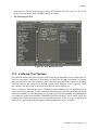
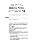
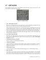
17 OPTIONS
This submenu is used to collect some KISMET menu-functions, which are used rarely, or do
not fit into one of the other menu groups.
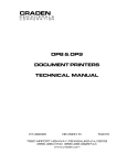
Figure 65: Options Menu
• Incr. VIEW-Input ON/OFF
Determines the input behaviour of the mouse device for the VIEWING commands. You can
choose between differential mode (default) and integrating mode.
When integrating (incremental) mode is OFF, the input value is calculated between the last
and the current position. A non-zero value is passed to KISMET only, when you move the
mouse. In incremental mode the mouse movement will be added to the last input value. I.e.
a non-zero input may be provided when the mouse is not moved on the table and while a
mouse button is pressed down. In this mode, the input value is reset to zero when you
release the mouse button(s).
• Incr. MOVE-Input ON/OFF
Determines the input behaviour of the mouse device for the MOVE-commands. You can
choose between differential mode (default) and integrating mode. See Incr. VIEW-Input
ON/OFF for details.
• SPACEBALL Interface ON/OFF
Enables or disables the SPACEBALL Interface.
• Collision Test Options
Calls the submenu to define the current options of the collision test algorithm. It is used to
define some extended tests and to specify the ‚minimum distance‘ test parameters. See 17.1.
Collision Test Options.
• FEM Postprocessing
Calls the submenu for Finite Element Postprocessing. See 17.2. FEM Postprocessing.
• Write Tree-File
This function can be used to generate an ASCII-file of the workcell datatree. The command
gives options when called to limit the amount of data dumped on the file. It can be used to
get a printout of all transformation parameters, matrices, GEO-names and -transformations
KISMET User Manual Page 111
OPTIONS
and a lot more. The file may become very big. The filename is fixed to ‚out_tree‘. It is saved
in the current directory where KIMSET has been started.
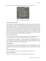
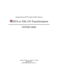
• File Management Tool
Figure 66: File Managemet Tool
17.1. Collision Test Options
This submenu defines the current options of the collision test algorithm. In active mode, the collision test encounters collisions, or near misses, between the moving mechanisms (or robots)
and environmental parts of the workcell. Also collisions between different robots are detected.
You can configure the collision test with the option in this submenu. You can specify a near
miss distance, the behaviour of the robot when the test detects a bump etc..
After a collision is detected, the beep is sounded and the colliding parts are highlighted (cyan
colour, wireframe rendering). For the numerical collision check, a set of hierarchical tests is performed by KISMET for each display cycle. The upper levels of the algorithm use bounding boxes around the model subassemblies (FRAMEs) and GEO-elements. Those details inside the
bounding box, which pass these tests, are not further checked. In the next step, a geometrical
surface test is performed with those parts, whose bounding boxes have collided.
KISMET User Manual Page 112
OPTIONS
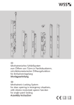
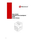
These multilevel tests give both, acceptable performance and a sufficient accuracy.
Figure 67: Collision Test Setup
• Test BODY Insides YES/NO
Toggle function for additional testing of BODY insides. For the first two stages of the collision test algorithm, i.e. for the testing of FRAME- and GEO-bounding boxes, the hardware
of the graphics workstation is used. The third stage actually tests geometric surfaces, this
testing is done in software. The bounding box test (hardware function) only detects a real
intersection between a GEO-part and the bounding box side facets. If a part is completely
inside the test box, for example when the box coincides with the workcell walls, this hardware test would fail and no further testing is done (stages 2 and 3 of the algorithm). To avoid
this failure of the test, you may activate an additional software test, which checks if any
parts are completely inside a FRAME-bounding box. It depends on the model topology if
this additional testing is necessary. The default mode is OFF (NO).
• Stop when Collide YES/NO
You can define, if the moving ROBOT model shall stop when a COLLISION is detected or
not. When the ROBOT stops, it will be displayed in the last non-colliding position.
In monitoring mode, the synthetic view shall represent the current position of the RHdevices, regardless of any collisions, i.e. the model should not stop (in KISMET) after a collision or near miss was detected. In simulation mode the stop function should be set to YES
to avoid geometric intersections between colliding parts.
• Set Min. Distance
This function is used to define the collision distance for the minimum distance test. The
parameter is defined in ‚mm‘. If this is set different from ‚0‘, the bounding boxes used for
the collision test are enlarged by the defined amount. This is, a near miss check is performed.
• Deactivate FRAME CT
Deactivate all parts connected to the selected FRAME from the collision test.
• Reactivate FRAME CT
Reactivates all parts connected to the selected FRAME for the collision test.
KISMET User Manual Page 113
OPTIONS
• Deactivate ROBOT CT
Deactiate a specific robot from the collision testing, e.g. CAMERAS, inactive robots defined in the KISMET scene but not relevant to the specific task ...
• Reactivate ROBOT CT
Reactivates a specific ROBOT for collision testing (which was proviously dactivated)
• SAVE CT-Pattern
Save the current settings to a SCRIPT-file. For reloading a stored collision test pattern, use
the SCRIPT button.
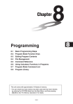
17.2. FEM Postprocessing
This functions are useful for postprocessing of results coming from calculations using the Finite
Element Method, Flow Processing or other timeseries datasets..
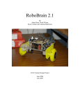
Figure 68: FEM Postprocessing
• VECTOR Display ON/OFF
Toggles the rendering of displacement vectors
• SCALAR Values ON/OFF
Toggles the overlay display of the scalar values as strings at each node
• FRINGE Display ON/OFF
Toggles the display of stress fringes, i.e. coloured tiles acoording to the stress values at the
nodes.
• TILE Display ON/OFF
Toggle the display of the displaced FE-shell
• Displace SHELL ON/OFF
KISMET User Manual Page 114
OPTIONS
Toggles the rendering of the displacement shell
• Displace VECTORS ON/OFF
Toggles the rendering of displacement vectors
• Colour Code Window ON/OFF
Toggles the rendering of a window with a colourbar for the stress/velocity data
• Scale Factor ON/OFF
Is used to scale the displacement vectors
• SCALE DISPLACEMENTS ON/OFF
Toggles between scaled and unscaled rendering
• MOVIE-Player
The MOVIE-Player menu is used to control display of time-series data like ISOSURFACE
geometries and vector fields in KISMET. The control buttons are similar to those of a CD or
tape player with the options (from left to right):
• One timeframe back
• Play (automatic forward function), draws frame after frame
• Advance one timestep
Figure 69: The FEM Movie Player Panel
KISMET User Manual Page 115
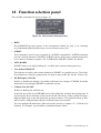
18 Function selection panel
The available commands are shown in figure 70.
Figure 70: The Function Selection Panel
• HELP
The KISMET-Help pages appear, if the environment variable kis_help is set. Normally
kis_help should point at the directory /usr/local/kismet/kismet_help.
• SCRIPT
This command is used to start execution of a SCRIPT-command file. SCRIPT-commands
provide a textual interface to KISMET. SCRIPTs can be used to store command sequences
or to control a animation sequence. See "USER DATA SPECIFICATION" for details.
• NEW MODEL
KISMET starts a new model looking for .sim files in the current working directory.
• User-defined MODULE
This function is used to start external modules to KISMET as a parallel process. The available submenus are listed in a popup-menu. To make an entry in this list, use the .kismetrc file.
• WFRM display ON/OFF
Enables or disables the display of available workframes. See chapter 12 WFRM for further
information concerning the KISMET workframe concept.
• Collision Test ON/OFF
Enables or disables the collision test.
In the first step of the test all FRAME boxes of the model are tested for the moving parts. If
any hit accurs, the second stage of the test checks the GEO-boxes. If they collide too, then a
third and final stage in the test checks the geometry surfaces. This approach taken in KISMET is both, computationally effective and at the same time accurate.
You can configure the behaviour of the test to some extend (see chapter 17.1. Collision Test
Options). For example, you can define a minimum distance check.
KISMET User Manual Page 116
19 Fast Keys
Some KISMET-commands can be executed by means of FUNCTION-KEYs instead of popup
menus or panel-buttons. This method is used for these commands for two reasons:
1. to save time for the user during KISMET operation (no walking up and down the
menu-tree).
2. for some commands, a free screen is required and/or the mouse input channels are
used.
The following section describes in detail each funktion key:
• C-Key
This function key is used to send a CAMERA-message to the real camera control system.
The active CAMERA is used.
• D-Key
Enables „Diagnostic“-mode. In this mode some system model and system parameters are
printed to the textport. This mode is mainly used during KISMET software development,
but some users may find the output useful. The amount and type of printed data may vary
between different KISMET-versions. For this reason no further decumentation is given here.
Just try and see what happens.
• E-Key
The „E-Key“ can be used to disable/enable the BEEP at your SGI-workstation. Usually
KISMET is using the BELL sound (BEEP) to attract the operators attention for errors,
warnings and requests. Sometimes you may want to switch it off. The default is beep ON.
• F-Key
Enables/disables the FULLSCREEN-mode. In this mode, the whole graphics display is
used as the scene viewport, the resolution is increased.
• G-Key
This function is used to enable TIMESERIES-output to a file. This is, for each display cycle
(program iteration step), the execution time, all joint-positions and the TCP-position is written to an ASCII-output file. These position data are used by the utility diagram and other
programs.
The TIMESERIES-file is saved into the path:
$kis_home/teachlib/pos_data/<filename>
The <filename> is defined by the user when the „G-KEY“ was pressed.
The command works only under following conditions:
• the output is started only if a robot program (IRDATA) is executed.
• the „Repeat“-mode must be NON-REALTIME. This is necessary for KISMET to get
constant time intervals for the simulation and to calculate with some accuracy the execution time
• the active ROBOT is used
• to use this command option proceed as follows:
KISMET User Manual Page 117
Fast Keys
1. ACTIVATE the robot for which you like to generate the TIMESERIES-data
2. LOAD an IRDATA-program
3. SET the program simulation mode to NON-REALTIME
4. ENABLE the TIMESERIES option by pressing the „G-Key“
5. KISMET will ask you to ENTER the <filename>
6. START the robot program. KISMET will now write to the file.
KISMET will automatically disable this mode when the robot program is finished
• H-Key
This function enables the KISMET HELP-utility. The HELP-utility allows to display KISMET help-pages in a seperate overlay-window. Each help-page explains a specific TOPIC.
The system is organized in a top-down help tree, i.e. the higher levels in the tree display
more general TOPICS, whereas the lower levels explain in detail every command available
in KISMET. From inside the HELP-window you may select in most cases new TOPICS.
Use the <ESC>-key to quit the HELP-system.
If you press the „H-Key“, the HELP-function works as follows:
• When a valuator function is attached (no menu is visible on the display), then the first
(most general) KISMET-manual page is shown.
• When a menu is displayed and you press „H-Key“ with the cursor outside the menuarea, the manual-page for the whole menu is shown.
• When a menu is displayed and you press „H-Key“ with the cursor inside the menuarea, the manual-page for that specific (highlighted) menu-command is shown.
• I-Key
This function key displays the FZK-logo in the workcell viewport and gives licensing information in the text panel display.
• K-Key
Enables/Disables the CAMERA-view overlay window. The virtual CAMERA to be simulated (i.e. the „actual CAMERA“) is selected in the menus „Display Select“ --> „Camera
view control“ --> „Select Camera“.
• L-Key
Enables/Disables the simulation of ELASTOMECHANICS in KISMET. If the required
parameters are defined in the application model database, this function will show you the
bending and torsion of the mechanisms under user-definable load conditions. The default
value is elastomechanics OFF.
• M-Key
Gives a memory statistics of the current simulation status in the textport (diagnosis
function). Printed are the numbers of GEO-elements (incl. instanced parts), GEO-CLUSTER (unique GEO-parts), FRAMES (assembly coordinates systems), numbers of GEOpoints and -normals. For each of these datatypes, the amount of used memory is displayed.
KISMET User Manual Page 118
Fast Keys
• N-Key
This is the magic „accelleration“ key for increasing the display performance. By default,
KISMET draws all active GEO-elements in the application model. When the „N-Key“ is
pressed, KISMET checks which parts of the model are currently visible in the main viewport. These parts are marked and remain active for further display. All currently invisible
GEO-elements, i.e. those outside the window, are disabled for further display until the „NKey“ is pressed again, or everything is enabled using the „F1-Key“. Using the „N“-Key can
give a drastic increase in display performance, if only some parts of the model are currently
visible and required for display.
Please note that for all following viewing operations (like „Zoom“, „Change View-Direction“ etc.) the disabled parts still remain invisible. KISMET does not check by itself, which
parts would become visible when the window attributes are modified by some user interaction. So, if you miss some elements of your model, use the „N-Key“ again, or enable all
parts with the „F1-Key“. The test carried out after „N-Key“ is very intensive in computing
time. So, it would not be very useful at all to do the test in KISMET for every redraw cycle.
• R-Key
This key is used to enter a new program step in „Teach“-mode. The new robot-program
command is selected from a menu. For each robot programming code, a dedicated „Teach“menu (panel) is displayed each time you press the „R-Key“. Then the command is chosen
from this menu (submenus are called if necessary).
Another way of robot programming (textual programming) is possible in KISMET, using
the off-line programming module (OLP-module). This is called up from the „Module“-submenu.
Currently simple geometry ad hoc robot teaching is possible in KISMET for the programming codes:
• IRDATA
• Pseudo Siemens SRCL
• S-Key
Enables/disables STEREO-mode. To use this option, your graphics workstation must be
equipped with stereo hardware (stereo glasses, 120Hz monitor etc.).
• W-Key
This command is used to perform a depthpass-filter calculation of the main workcell view
(scene antialiasing) using the accumulation buffer. The function is useful to achieve an
antialiased image in solid drawmodes. Because the calculation may take a few seconds,
only one pass is carried out each time you press „W-Key“.
• Y-Key
This key is used to define a target point for inverse CAMERA kinematics during
CAMERA-simulation. To use this command, you must be in the „top + side view“ display
mode. A crosshair cursor is displayed after pressing „Y-Key“. First you specify the target
position in the „top“-view (clicking LM), followed by a LM-click in the side view. Only the
elevation coordinate (hight, Y-value) is taken from the side view.
KISMET User Manual Page 119
Fast Keys
• F1-Key
Reactivates all GEO-parts for display. This function can be useful after previous use of the
„N-Key“.
• F2-Key
This function is used to inquire the hardware resources of your graphics workstation. The
data is written to the file ‚SGI_type‘ in the current directory. Please refer to the glGet(3G)
manual page for a detailed description of the various parameters.
• F3-Key
This command is used to perform a depthpass-filter calculation of the main workcell view
(scene antialiasing) using the accumulation buffer. The function is useful to achieve an
antialiased image in solid drawmodes. Because the calculation may take a few seconds,
only one pass is carried out each time you press „F3-Key“.
• F5-Key
This function key starts the calculation of one image in RAYCASTING-mode. In raycasting
mode, KISMET calculates correctly „real“ shadows in the scene, but no mirror reflections
or light refraction in transparent objects. To calculate these effect too, use „RAYTRACING“-mode („F6-Key“). In fact, the raycasting mode is using the same routines in KISMET as raytracing. But it is executed with a ray-depth limit of 1. KISMET is using all parts
of the user defined lighting model (file ‚.lgt‘) and material definitions (file ‚.mat‘) for the
computation. To study the approximate lighting conditions in the image in the normal drawing modes („Gouraud user lights“) in realtime, you should start KISMET with the „-l“option.
Note: Only one viewport (i.e. the main viewport) is calculated.
The resulting image is automatically saved into the directory ‚$HOME/rtimages‘ as an SGIRGB imagefile. The name of the file is ‚rt_xx.rgb‘, where ‚xx‘ is the current number + 1 of
all files in that directory with the suffix ‚.rgb‘. The portion of the screen saved into the
image file depends on wether the calculation is carried out in „FULLSCREEN“-mode or
not. In normal mode, only the big viewport is saved, i.e. the screen area (120, 1119, 192,
991). In „FULLSCREEN“-mode the screen area (1, 1278, 1, 1022) is saved in the RGB-file.
• F6-Key
This function key starts the calculation of one image in RAYTRACING-mode. In addition
to shadows, the raytracing mode can also calculate light reflection between objects and
refraction in transparent parts. The resulting display is saved into an image file when the
calculation is finished (see „F5-Key“).
• F7-Key
Is used to generate an SGI-image file (SGI-rgb format) of the workcell view. In non fullscreen mode, an image of size 1000x800 pixels is saved, in fulls-screen mode, the image
size corresponds to the display size (typically 1280x1024 pixels). The resulting image file is
written into the directory ‘$HOME/images’, if this directory doesn’t exist, the file is written
into the current directory. The filename is generated automatically by KISMET, the files are
called ‘im_xx.rgb’, where ‘xx’ is the current number + 1 of all files in that directory with the
suffix ‚.rgb‘. To save as well the current KISMET-panel together with the workcell view,
KISMET User Manual Page 120
Fast Keys
please refer to the F10-Key command.
• F9-Key
This function enables/disables the SMEAR-mode. When SMEAR is enabled, the workcell
display is not cleared before the next rendering cycle. This function can be used for example
to visualize the workspace of a ROBOT.
• F10-Key
Is used to generate an SGI-image file (SGI-rgb format) of the workcell view together with
the MMI panel area of the KISMET display. The image size is typically 1280x1024 pixels.
Everything else is similar as in the F7-Key command.
• F11-Key
The lighting model is switched to „Local-Viewer“ mode (toggle-function). By default, all
lightsources are assumed to be located infinite far away. In „Local-Viewer“ mode the
lighting calculations become more realistic, i.e. the quality of the image is increased. A drawback is, that the graphics performance is decreased.
• F12-Key
The lighting model is switched to „Twosided-Lighting“ mode (toggle-function). The default
state in KISMET is OFF.
• Esc-Key (Escape)
This function key is a shortcut to the „QUIT“-command (Stop KISMET).
• Home-Key
Enables drawing of the ‘FZK’ company logo in the lower left corner of the workcell view
area (toggle-function).
KISMET User Manual Page 121
20 The Full Screen Mode
20.1. Introduction
If you run KISMET in the Full Screen Mode, the Stereo Mode or the Window-Mode, you have
to use pop-up menus instead of the menu-panels. By pressing the right mouse button (RM) the
uppermost menu in the command hierarchy will appear. All other menus are invoced from the
’Main menu’. To select a specific command or a sub menu (indicated by >) press LM or MM.
Notice: Since in Full Screen Mode most of the popup-menu commands and/or submenus have
slightly different names as in the panel-MMI mode, all panel-command titles and the corresponding submenu-names are listed here. You will find after each command a reference to the
command used with the panel MMI.
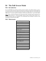
20.2. Main menu
Move Modes
Activate ROBOT
Teach
Repeat
Viewing
Drawmode
Dispaly Select
Collision-Test on/off
Define TCP
Define ZEROPOINT
Edit Geo
Edit FRAME
Edit ABSTRACT
Edit WFRM
Miscellaneous
Exec SCRIPT File
Start MODULE
ROBOT online
Elastomechanics
Dynamics
Control
Quit
>
>
>
>
>
>
>
>
>
>
KISMET User Manual Page 122
The Full Screen Mode
Move Modes
See chapter 7.2. "Motion: List of Commands" on page 26.
Activate ROBOT
See "ACTIVATE MECHANISM" in chapter 7.2. "Motion: List of
Commands" on page 26.
Teach
See chapter 11 "TEACH" on page 59.
Repeat
See chapter 10 "SIMULATE" on page 51.
Viewing
See chapter 8 "VIEWING" on page 32.
Drawmode
See chapter 9.2.1 "Draw Parameters" on page 41.
Display Select
See chapter 9.2.2 "Display Modes" on page 45.
Collision Test on/off
See chapter 18 "Function selection panel" on page 116.
Define TCP
See "TCPF Setup" in chapter 7.2. "Motion: List of Commands"
on page 26.
Define Zeropoint
See "ZPF Setup" in chapter 7.2. "Motion: List of Commands" on
page 26.
Edit GEO
See chapter 15.2. "Edit GEO" on page 80.
Edit Frame
See chapter 15.3. "Edit FRAME" on page 89
Edit Abstract
See chapter 14.2. "DETAIL Submenu {Edit ABSTRACT}" on
page 75.
Edit WFRM
See chapter 12.2. "The WFRM Panel" on page 62.
Miscellaneous
See chapter 17 "OPTIONS" on page 111.
Exec Script-File
See "SCRIPT" in chapter 18 "Function selection panel" on page
116.
Start MODULE
See "User-defined MODULE" in 18 "Function selection panel"
on page 116.
ROBOT online
See "Monitor Mode ON/OFF" in chapter 13.2.1 "The Monitor/
Master-Mode Buttons" on page 70.
Elastomechanics
See chapter 16.3.1 "The Elastomechanics Panel" on page 101.
Dynamics
See chapter 16.3.2 "Dynamics Sub-menu" on page 103.
Control
See chapter 16.3.4 "The Control Panel" on page 108.
Quit
End KISMET
KISMET User Manual Page 123
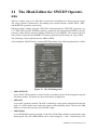
21 The 2Ded-Editor for SWEEP Operations
2Ded is a simple, easy to use 2D-editor for interactive modelling of a 2D sweep-area region.
The sweep contour is defined by a surrounding curve which consists of POLYLINE-, ARC-,
and B-SPLINE segments, respectively.
During geometry editing, using the "Edit GEO" submenu and the "CREATE" operation ( see
15.2. Edit GEO) with the SWEEP-primitives (rotational and translational SWEEPs), the 2Dgeometry editor 2Ded is started as another UNIX-process by KISMET. The results of the 2Dedit session are passed to the KISMET 3D-surface generator by file when you "Quit" 2Ded.
The following section explains the user MMI of 2Ded:
Afer starting the 2Ded-Editor by creating SWEEP-primitives the following submenu is visible:
Figure 71: The 2D Editing Panel
• Add POLYLINE
A new POLYLINE segment is started. Points are defined on the 2D drawing pad using the
LM mouse button. The points are interconnected by straight lines.
• ADD ARC
A new ARC segment is started. The ARC is defined by centre-point, startpoint and enclosed
angle. Use LM to define start- and centre-point (in this definition order). Then use the MM
button to increase/decrease the enclosed ARC-angle.
• Add B-Spline
A new B-SPLINE segment is started . Each click of LM defines another control point on the
drawing pad. The curve-PRECISION can be varied using the '+' and '-' function keys. The
KISMET User Manual Page 124
The 2Ded-Editor for SWEEP Operations
first and last control points of a B-SPLINE segment are always duplicated by 2Ded to guarantee CURVE continuity for interconnected segments.
• Term. B-Spline
Terminates the current B-Spline segment.
• Closed B-Spline
Terminates the current B-Spline segment by connecting start- and end-point to get a closed
B-Spline segment.
• MOVE
Allows to move the control points of a segment via the LM valuator input. To select a control point press LM near the points location. Then move the point by dragging the point
while LM is pressed down. The enclosed angle of ARC-segments can be changed via MM.
The current (active for editing) segment is highlighted in CYAN color.
• INSERT
This function is used to insert new control points for POLYLINE and B-SPLINE segments.
The new control point is inserted next to the position of the nearest control point when LM
is pressed down.
• DELETE
Deletes the control point nearest to the cursor when LM is pressed. A segment is deleted
when all of its control points are erased.
• Pan
Allows to move the origin of the drawing pad relative to the viewport. This function is equivalent to the "Move Viewpoint" command in KISMET.
• Scale
This function allows scaling of the drawing pad. LM decreases the pad-size by a factor 2
while MM increases the pad-size by a factor 2.
• Close
This function is used to connect curve segments with eachother. When segments are not
connected (default value) and two control of different segments have the same coordinates
then you can move these points independently from eachother. When these points are connected, for example the last control point of a POLYLINE segment and the startpoint of an
ARC-segment, both segments will change (move together) if the interconnecting coordinate
is changed by a "move"-operation.
The conour curve is closed by insertion of another POLYLINE edge.
• Connect
This function is used to connect curve segments with eachother. When segments are not
connected (default value) and two control of different segments have the same coordinates
then you can move these points independently from eachother. When these points are connected, for example the last control point of a POLYLINE segment and the startpoint of an
ARC-segment, both segments will change (move together) if the interconnecting coordinate
is changed by a "move"-operation.
KISMET User Manual Page 125
The 2Ded-Editor for SWEEP Operations
Two segments will be connected with eachother by a common control point. Translation of
one segment ("move") will shift the other, connected segment too.
• Curve Precision
For drawing, curves are interpolated using a polygonal representation. This parameter defines the number of interpolations (segments). The default value is 10, i.e. each curve segment, the curve between two control points, is rendered using 10 line segments.
• Set GRID Size
Allows to define the GRID intervall of the drawing pad. The initial value of the GRID-size
is 5mm.
• Point SNAP ON/OFF
Enable/Disable the SNAP function. When the SNAP option is ON (by default), all edited
control points will move the edited coordinate to the nearest GRID point of the drawing
pad.
• DONE
This command is used when the editing session in 2Ded is successfully finished. The cureve
data will be passed to KISMET. The 2D-countour is used by the 3D-surface generator as
sweeping-area.
• CANCEL
The editing session is stopped (escaped, cancelled) without saving the the segment data to a
file. There is no datafile passed to the 3D-surface generator in KISMET. This is, the "Create
GEO"-operation in KISMET is cancelled too.
• CLEAR
Deletes all created segments and clears the pad.
KISMET User Manual Page 126
22 References and Literature
Additional KISMET Documentation
[1]
Kühnapfel, U.: „KISMET - User Data Specification“;
unpublished KFK-Report 17.01.01P27A (Dec 1989).
[2]
Kühnapfel, U.: „Grafische Realzeitunterstützung für Fernhandhabungsvorg änge in
komplexen Arbeitsumgebungen im Rahmen eines Systems zur Steuerung, Simulation
und Off-Line-Programmierung“; Dr.-Ing. Dissertation, University Karlsruhe (Nov
1991). In German Report KFK5052,KFK,Karlsruhe (1992)
[3]
Baumann, K.: “Werkzeuge und Experimente zur Roboterprogrammierung.“ unpublished KFK-Report 17.03.03P16A (1990). In German
[4]
Kuhn, Ch.: "Modellbildung und Echtzeitsimulation deformierbarer Objekte zur Entwicklung einer interaktiven Trainingsumgebung für die Minimal-Invasive Chirurgie",
(in German !) Dissertation Universität Karlsruhe; Wissenschaftliche Berichte Forschungszentrum Karlsruhe - FZKA 5872, ISSN 0947-8620, Jan. 1997
KISMET Applications in Robotics and Remote-Handling
[5]
Kühnapfel, U., Leinemann, K., Schlechtendahl, E.G.: “Graphics Support for JET
Boom Control.“
Proc. International Topical Meeting on Remote Systems and Robotics in Hostile
Environments. Pasco, Wa., March 29 April 4, 1987, 28-34
[6]
Kühnapfel, U.: „GBsim - JET Graphical Boom Simulator / Operators Manual“,
unpublished KFK-Report 17.01.01P02C (August 1987).
[7]
Leinemann, K., Kühnapfel, U., Ludwig, A.: “CAD-Model Based Remote Handling
Control System for NET and JET.“
15th SOFT, Utrecht, 19.-23.9.1988
[8]
Kühnapfel, U.: “KISMET - 3D-Grafik zur Planung, Programmierung und überwachung von Telerobotics-Applikationen.“
in VDI-Berichte Nr. 861.3, 71-86, VDI-Verlag, Düsseldorf (1990)
[9]
Leinemann, K., Kühnapfel, U., Schlechtendahl, E.G.: “NET Remote Handling Control System with CAD-Support.“
Proc. ANS 3rd Topical Meeting on Robotics and Remote Systems, Charleston, SC,
USA, 13.-16.3.1989, p.5.2.1-5.2.8
[10]
Kühnapfel, U., and Ludwig, A.: “Graphics and CAD Support for NET/ITER Boom
Control.“
Proc. 16th SOFT, London, 3.-7. Sept. 1990, North-Holland, Amsterdam, Vol. 2, 13471352 (1991)
[11]
Leister, P., Kühnapfel, U., Ludwig, A.: “Computer Aided Simulation of a Remote
Steam Jet Exchange in a Dissolver Cell.“
Proc. ANS 4th Topical Meeting on Robotics and Remote Systems, Albuquerque, NM,
USA, 353-364 (1991)
KISMET User Manual Page 127
References and Literature
[12]
Leinemann, K., Kühnapfel, U., Ludwig, A.: “Remote Handling Control with Graphical Man-Machine Interface for NET and JET.“
in: Robotics and Remote Maintenance Concepts for Fusion Machines, IAEA-TECDOC-495, Wien, 215-226 (1989).
[13]
Patentschrift: “Verfahren zur Manipulation in unzug änglichen Arbeitsbereichen.“
Patentschrift DE 3925275 C2, Deutsches Patentamt, Bundesdruckerei (1991)
[14]
Leinemann, K.: “NET Remote Workstation.“
Report KfK-4785, Karlsruhe (1990)
[15]
Leinemann, K.: “Advanced Tele-Operator Support for Fusion Plant Maintenance.“
Proc. ‚91 Int. Symp. on Advanced Robots Technology, Tokyo, Japan, 5-7 März 1991
Robotics, Robotics-Simulation
Medical Applications of KISMET
[16]
U. Kühnapfel, B. Neisius : "CAD-modellbasierte, graphische Echtzeit-Computersimulation für die endoskopische Chirurgie". In German. KfK-Nachrichten, Jahrgang
25, Nr. 4 1993, 201-206
[17]
Kühnapfel, U., Krumm, H.G., Kuhn, C., Hübner, M., Neisius, B.: Endosurgery simulations with KISMET: a flexible tool for surgical instrument design, operation room
planning and VR technology based abdominal surgery training Virtual Reality World
’95, : Conference Documentation, Stuttgart, 21.-23.Feb. 1995, München: Computerwoche Verlag, 1995, 165-171
[18]
U. Kühnapfel, Ch. Kuhn, M. Hübner, H.-G. Krumm: "VR Technology based Minimally Invasive Surgery Training using the KISMET Software", Proc. IMAGINA‘96,
Monte Carlo, 21-23 Feb. 1996, 145-164
[19]
Hübner, M., Kühnapfel, U.: "Real-Time Volume Visualization of Medical Image Data
for Diagnostic and Navigational Purposes in Computer Aided Surgery", 10th Internat.Symp.on Computer Assisted Radiology (CAR ’96), Paris, F,, June 26-29, 1996,
751-756
[20]
Kühnapfel, U., Kuhn, Ch., Hübner, M., Krumm, H.G., Maaß, H., Neisius, B.: "The
Karlsruhe Endoscopic Surgery Trainer as an example for Virtual Reality in Medical
Education", Minimally Invasive Therapy and Allied Technologies (MITAT) 1997: 6,
122-125, Blackwell Science Ltd.
Robotics Basics and Theory, Background reading
[21]
Paul, R.P.: “Robot Manipulators - Mathematics, Programming and Control.“
MIT-Press, Cambridge, Mass. (1981)
[22]
Lee, C.S.G.: “Robot Arm Kinematics, Dynamics and Control.“
Computer, Dez. 1982, 62-80 (1982)
[23]
Desoyer, K., Kopacek, P., Troch, I.: “Industrieroboter und Handhabungsger äte - Aufbau, Dynamik, Steuerung, Regelung und Einsatz.“
Oldenbourg, München, Wien (1985)
[24]
Adler, A.: “Rechnerunterstützter Robotereinsatz.“
Hüthig, Heidelberg (1988). In German
KISMET User Manual Page 128
References and Literature
Robot-Languages, Programming, Standards
[25]
VDI-Richtlinie 2861, Blatt 2: “Montage- und Handhabungstechnik: Kenngrößen für
Handhabungseinrichtungen.“
VDI-Verlag, Düsseldorf (1982)
[26]
Blume, C., Jakob, W.: “Programming Languages for Industrial Robots.“
Springer, Berlin (1986)
[27]
Blume, C., Jakob, W., Favaro, J.: “PASRO - Pascal and C for Robots.“
Springer, Berlin (1987)
[28]
DIN-Norm 66313, Teil 1: “IRDATA-Schnittstelle zwischen Programmierung und
Robotersteuerung. Allgemeiner Aufbau, Satztypen und übertragung.“
Beuth Verlag, Berlin (1990)
Computer Graphics, CAD/CAM
[29]
Hearn, D., Baker, M.P.: “Computer Graphics.“
Prentice Hall International (1986)
[30]
Foley, J.D., van Dam, A.: “Fundamentals of Interactive Computer Graphics.“
Addison-Wesley, Reading, Mass. (1982)
[31]
Newman, W.M., Sproull, R.F.: “Principles of Interactive Computer Graphics.“
McGraw-Hill, New York (1979)
[32]
Encarnacao, J., Schlechtendahl, E.G.: “Computer Aided Design. Fundamentals and
System.“
Springer, Berlin (1983)
[33]
Grätz, J.F.: “Handbuch der 3D-CAD-Technik: Modellierung mit 3D-Volumensystemen.“ Siemens AG, Berlin, München (1989)
CAD Data Exchange, Neutral Formats
[34]
Schlechtendahl, E.G. (ed.): “Esprit Project 322: Specification of a &cadid2. Neutral
File for CAD-Geometrie. Version 3.3.“
Springer, Heidelberg (1988)
[35]
Schlechtendahl, E.G. (ed.): “Esprit Project 322: &cadid2.. CAD Data Transfer for
Solid Models.“
Springer, Heidelberg (1989)
[36]
Brändli, N., Mittelstädt, M.: “Exchange of Solid Models: Current State and Future
Trends.“
Computer-Aided Design, Vol.21, Nr.2, 87-96 (1989)
[37]
Mittelstädt, M.: “The CATIA-KISMET Link at JET - Concept, Realization, and Operation.“
unpublished KFK-Report 17.01.01P19A (June 1989)
[38]
Pleschounig, W.: “The JET Ex-Vessel Display.“
unpublished KFK-Report 17.01.01P35A (May 1991)
"Elastomechanics" Submenu
[39]
Krumm, H.-G.; Kuehnapfel, U.: "Esprit Project 5542(MDS)", unpublished report,
KISMET User Manual Page 129
References and Literature
Kernforschungszentrum Karlsruhe, November 1991
[40]
Judd, R.P.; Falkenburg, D.R.: "Dynamics of Nonrigid Robot Linkages",
IEEE Transactions on Automatic Control, Vol. AC-30, 1985, p.499-502
[41]
Kopacek,P.; Desoyer, K.; Lugner, P.: "Modelling of flexible Robots - An Introduction", Proceedings of the IFAC Symposium on Robot Control 1988 (SYROCO 1988),
Karlsruhe
"Dynamics" Submenu
[42]
Krumm,H.-G.: "Real Time Calculation of Static Deflections and Real Time Dynamics
for Robots with KISMET",
Modelling and Simulation 1992, Proceedings of the 1992 European Simulation Multiconference (ESM 92),
[43]
York Shabana, A.A.: "Dynamics of Multibody Systems",
John Wiley & sons, New York 1989
[44]
Walker,O.; Orin, D.E.: "Efficient Dynamic Computer Simulation of Robotic Mechanisms",
Journal of Dynamic Systems, Measurement and Control, Vol. 104, p. 205-211, September 1982
[45]
Johnson, C.: "Numerical solution of partial differential equations by the finite element
method",
Cambridge University Press, Cambridge
[46]
Bronstein,I.N.; Semendjajew, K.A.: "Taschenbuch der Mathematik", 20. Auflage, p.
807-809, Thun, Frankfurt/Main, 1981
"Control" Submenu
[47]
Yuh, J. and Tissue, D.K.: "Adaptive Control for Mechanical Manipulators having a
Joint Compliance",
1990
[48]
Unbehauen, H.: "Regelungstechnik I,II",
Vieweg, 1982
KISMET User Manual Page 130
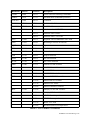
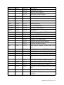
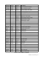
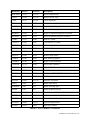
Appendix•A- List of implemented IRDATA-Commands
The following table shows a list of IRDATA-functions available in the KISMET IRDATA-interpreterr. For a detailed description of each command, please refer to [28] DIN-Norm 66313,
Teil 1: “IRDATA-Schnittstelle zwischen Programmierung und Robotersteuerung. Allgemeiner
Aufbau, Satztypen und übertragung.“
Mnemonic
HS-No
Com-No
Description
MOVE
5000
500 et
Point-to-Point (PTP) movement
501 et
Linear (LIN) movement
NULPOS
5128
502
Move to robot specific ZERO-position
MOVREF
5256
503
Move to robot specific REFERENCE-position
MOVECR
5512
504 et
Circular Movement
MOVACT
5513
505
returns TRUE, if the robot executes a motion
command
ENDPAR
5514
506
stops parallel program execution for movements
MOVSTP
5515
507 et
stops a robot motion
ACCEL
2001
200 et
define TCP-accelleration for LIN, given in percentage of max. value
201 et
define accell. all joints, given in percentage of
max. value
202 et
define accell. one joint in percentage of max.
value
203 et
define TCP-speed for LIN-motion, given in percentage of max. value
204 et
define speed all joints, given in percentage of
max. value
205 et
def. speed one joint in percentage of max. value
FEDRAT
2003
MOVTIM
2004
206 et
Set motion command execution time
ORICHA
2005
207 e
Define orientation change mode
POSCP
2006
208
LIN-motion flypoint mode
POSAX
2007
209
joint motion flypoint mode
Tabelle 7: List of IRDATA Commands
KISMET User Manual Page 131
Mnemonic
HS-No
Com-No
Description
USEIR
2008
210 et
Select robot for following commands
AXREL
2030
211 et
Set hand mode (redundant positions)
LINENO
1000
100 et
Comment
TOOLNA
17001
1700
global tool definition
TOOLDE
17002
1701 et
Set TCP-offset
ABS
21010
2100 e
Absolute value: INTEGER
2101 e
Absolute value: REAL
2102 e
Absolute value: VECTOR
NEG
21020
2103 e
Negation: INTEGER/REAL/VECTOR
RND
21030
2104 e
Rounding to nearest INTEGER
SQRT
21100
2105 e
Square root
SIN
21110
2106 e
Sine function
COS
21120
2107 e
Cosine function
TAN
21130
2108 e
Tangent function
ASIN
21140
2109 e
Arc sine function
ACOS
21150
2110 e
Arc cosine function
ADD
21200
2111 e
Add INTEGER variables
2112 et
Add REAL variables
2113 et
Add VECTORs
2114 et
Add WORLD variables
2115 e
Subtract INTEGER variables
2116 et
Subtract REAL variables
2117 et
Subtract VECTORs
2118 et
Subtract WORLD variables
2119 et
Multiply INTEGER variables
2120 et
Multiply REAL variables
2121 et
VECTOR scalar product
2122 et
VECTOR cross product
2123 et
Rotate VECTOR
2124 et
WORLD (Matrix) multiplication
SUB
MUL
21216
21220
Tabelle 7: List of IRDATA Commands
KISMET User Manual Page 132
Mnemonic
DIV
HS-No
21230
Com-No
Description
2125 et
Transform VECTOR
2126 et
Rotate WORLD (Matrix)
2127 et
Transform WORLD variable
2128 e
Divide INTEGER variable
2129 et
Divide REAL variable
2130 et
Divide VECTOR variable
MOD
21240
2131 e
Modulus function
VECDOT
21250
2132 et
VECTOR dotproduct
WLDREL
21260
2133 et
WORLD Transformation
ATAN2
21270
2134 e
Arc tangent
EQ
21280
2135 e
EQUAL compare CHARACTER variables
2136 e
Compare INTEGER variables
2137 e
Compare REAL variables
2138 e
Compare VECTOR variables
2139 e
Compare ORIENTATION variables
2140 e
Compare WORLD variables
2141 e
NOT EQUAL compare CHARACTER variables
2142 e
NOT EQUAL compare INTEGER variables
2143 e
NOT EQUAL compare REAL variables
2144 e
NOT EQUAL compare VECTOR variables
2145 e
NOT EQUAL compare ORIENTATION variables
2146 e
NOT EQUAL compare WORLD variables
2147 e
GREATER compare INTEGER variables
2148 e
GREATER compare REAL variables
2149 e
LOWER or EQUAL compare INTEGER variables
2150 e
LOWER or EQUAL compare REAL variables
2151 e
GREATER or EQUAL compare INTEGER
variables
NE
GT
LE
GE
21281
21282
21283
21284
Tabelle 7: List of IRDATA Commands
KISMET User Manual Page 133
Mnemonic
LT
HS-No
21285
Com-No
Description
2152 e
GREATER or EQUAL compare REAL variables
2153 e
LOWER THAN compare INTEGER variables
2154 e
LOWER THAN compare REAL variables
NOT
21276
2155
NOT operation (bit function)
AND
21277
2156 e
logical AND function
OR
21278
2157 e
logical OR function
XOR
21279
2158
exklusive OR function
GEN
21400
2159 et
Define VECTOR variable
2160 et
Define ORIENTATION variable
2161 et
Define WORLD variable
2162 et
Define JOINT variable
2163
Define ADX variable (additional axis) .
2164 e
Conversion: INTEGER -> REAL
2165 e
Conversion: REAL -> INTEGER
2166 e
Conversion: INTEGER -> CHARACTER
2167 e
Conversion: CHARACTER -> INTEGER
2168
Conversion: WORLD -> JOINT
2169
Conversion: JOINT -> WORLD
2170 e
Conversion: INTEGER -> POINTER
2171 e
Conversion: POINTER -> INTEGER
TYPCON
21500
NUMCON
21502
2172
Number Conversion
STRCON
21503
2173
STRING Conversion
CONCAT
21600
2174
Concatenate STRINGs
EXTRCT
21610
2175
Extraction of STRINGs
GETCHR
21620
2176
getchar function
SETCHR
21630
2177
setchar function
CHECK
21700
2178
range check
DEFSYM
22001
2200 e
Reserve memory for symbolic variables
GENSAR
22002
2201 e
Reserve memory for symbolc arrays
Tabelle 7: List of IRDATA Commands
KISMET User Manual Page 134
Mnemonic
HS-No
Com-No
Description
DEFVAR
22004
2202 e
Reserve memory for variables
GENARR
22005
2203 e
Reserve memory for arrays
MOVDAT
22020
2204 et
Assign CHARACTER variable
2205 et
Assign BOOLEAN variable
2206 et
Assign INTEGER variable
2207 et
Assign REAL variable
2208 et
Assign VECTOR variable
2209 et
Assign ORIENTATION variable
2210 et
Assign WORLD variable
2211 et
Assign JOINT variable
2212
Assign ADX variable
READIR
22021
2213 e
Read current robot position
CLRST
22022
2214 e
Delete uppermost stack element
ABSADR
22050
2215 e
Calculate absolute address
LIMU
22080
2216 e
Length in memory units
PBEG
22100
2217 et
Program Start
PEND
22150
2218 et
Program End
PSTOP
22190
2219 e
Program Stop
BLBEG
22200
2220 et
Block Start
BLEND
22210
2221 et
Block End
CALL
22220
2222 et
Procedure Call
PRCBEG
22230
2223 et
Procedure Begin
PRCEND
22240
2224 et
Procedure End
TSKBEG
22250
2225
Task Begin
TSKEND
22260
2226
Task End
GOTO
22300
2227 et
unconditional JUMP
IF
22310
2228 et
logical JUMP
FOR
22330
2229 et
Begin of FOR loop
FOREND
22340
2230 et
End of FOR loop
WHILE
22350
2231 et
Begin of WHILE loop
Tabelle 7: List of IRDATA Commands
KISMET User Manual Page 135
Mnemonic
HS-No
Com-No
Description
WHLEND
22355
2232 et
End of WHILE loop
UNTIL
22360
2233 et
End of UNTIL loop
CASE
22370
2234 et
CASE statement
NOOP
22380
2235 et
No Operation
PARBEG
22500
2236
Begin of parallel program execution
PAREND
22510
2237
End of parallel program execution
SEQBEG
22520
2238
Begin of sequential program execution
SEQEND
22530
2239
End of sequential program execution
START
22535
2240
Start of a TASK
CANCEL
22540
2241
Cancelation of a TASK
SUSPND
22550
2242 et
TASK Suspension
TSKHLD
22560
2243
TASK Hold
TSKCON
22570
2244
TASK Continuation
TSKSTA
22580
2245
Return TASK status
STARTX
22590
2246
Start another program
CONBEG
22700
2247
Begin of start condition
CONEND
22710
2248
End of start condition
DURBEG
22720
2249
Begin of duration
DUREND
22730
2250
End of duration
SEMINI
22800
2251 et
Initialise a SEMAPHORE variable
WAIT
22810
2252 et
WAIT-Operation
SIGNAL
22820
2253 et
SIGNAL-Operation
LIMIT
3000
300
Define joint limits
WORKSP
3001
301
Define working space
PROSP
3002
302
Define prohibited space
DLHEAD
14001
1400 et
Header command of a datalist
DLEND
14002
1401 et
End command of a datalist
DLDAT
14100
1402 et
Name and constants of a datalist
DLOPEN
14200
1403 e
Open existing datalist
DLGEN
14201
1404
Open new datalist
Tabelle 7: List of IRDATA Commands
KISMET User Manual Page 136
Mnemonic
HS-No
Com-No
Description
DLCLS
14202
1405 e
Close datalist
DLEIN
14203
1406 e
Read datalist element
DLEOUT
14204
1407
Write datalist element
ROBNUM
19010
1900
Number and joint count of a robot
ROBAX
19020
1901
Type and motion range of single axes
IOSTAT
23010
2300
Request I/O-status of an I/O-channel
DATOUT
23100
2301 et
Data output (terminal)
DATIN
23200
2302 et
Data input (terminal)
RPOMPT
23300
2303
Wait for condition or start signal
DIGIN
23610
2304 e
Digital input
ANIN
23620
2305 e
Analogue input
DIGOUT
23710
2306 e
Digital output
ANOUT
23720
2307 e
Analogue output
28xxx
2235 e
Application specific extensions of command
family 28000 are ignored
29xxx
2235 e
Application specific extensions of command
family 29000 are ignored
Tabelle 7: List of IRDATA Commands
Abbreviations:
Mnemonic
Mnemotechnical Command Name (see „VDI-Richtlinie 2863“).
HS-No
IRDATA command No (see „VDI-Richtlinie 2863“)
Com-No
Internal Codenumber :
e
Command is executable in KISMET
t
Command is teachable
x
Arbitrary number 0 to 9
KISMET User Manual Page 137