1
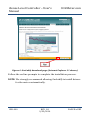
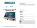
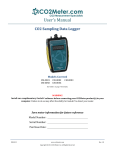
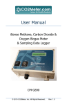
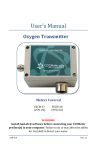
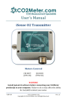
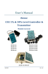
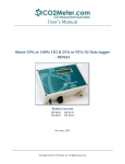
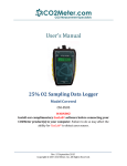
User’s Manual iSense CO2 1% & 30% Level Controller & Transmitter Models Covered CM-0042 CM-0043 CM-0044 CM-0045 CM-0042-NM CM-0043-NM CM-0044-NM CM-0045-NM CM-0045-NM-SP USR-009 www.co2meter.com Copyright © 2014 CO2 Meter, Inc. All Rights Reserved. Rev. 1.8 iSense Level Controller – User’s Manual CO2Meter.com WARNING! Install GasLab® software before connecting your CO2Meter product(s) to your computer. Failure to do so may affect the ability for GasLab® to detect your meter/sensor. If this happens, please follow the instructions shown in the “USB Driver Installation Instructions” section on page 30 of this manual. USR-009 REV. 1.8 9/23/2014 PAGE 2 of 35 iSense Level Controller – User’s Manual CO2Meter.com Save meter information for future reference Model Number: Serial Number: Purchase Date: USR-009 REV. 1.8 9/23/2014 PAGE 3 of 35 iSense Level Controller – User’s Manual CO2Meter.com Table of Contents WELCOME ......................................................................................................................5 IMPORTANT SAFEGUARDS .....................................................................................6 PACKAGE CONTENTS .................................................................................................7 GASLAB® SOFTWARE ...............................................................................................8 MINIMUM SYSTEM REQUIREMENTS ...................................................................................... 8 POWERING THE METER ........................................................................................ 10 PRODUCT OVERVIEW ............................................................................................ 10 THEORY OF OPERATION........................................................................................................ 12 OPERATION GUIDE ................................................................................................. 13 OUTPUT SETUP....................................................................................................................... 13 IAQ RELAY SWITCH SETTING .............................................................................................. 16 GH RELAY SWITCH SETTING ............................................................................................... 16 CONNECTING METER............................................................................................................. 17 COLLECTING DATA IN REAL-TIME ...................................................................................... 19 SETTINGS .................................................................................................................... 19 OUTPUTS SETTINGS ............................................................................................................... 20 CALIBRATION ........................................................................................................... 23 CALIBRATION PROCEDURE ................................................................................................... 24 MANUAL CALIBRATION ......................................................................................................... 25 APPENDIX ................................................................................................................... 27 A. METER SPECIFICATIONS ............................................................................................ 27 B. ACCESSORIES................................................................................................................ 29 TROUBLESHOOTING GUIDE................................................................................. 30 USB DRIVER INSTALLATION INSTRUCTIONS .................................................................... 30 SUPPORT .................................................................................................................... 31 WARRANTY................................................................................................................ 32 LIABILITY ................................................................................................................... 32 RETURNS .................................................................................................................... 33 CONTACT US .............................................................................................................. 33 USR-009 REV. 1.8 9/23/2014 PAGE 4 of 35 iSense Level Controller – User’s Manual CO2Meter.com Welcome Thank you for purchasing our meter. CO2Meter, Inc. is a Florida based business specializing in the design and manufacturing of gas detection and monitoring devices – mainly CO2. Our approach is one based in the science of gas and how best to accurately and repeatedly measure that gas for the end users purposes. Our business partners in agriculture, HVAC, science, safety, research, pharmaceuticals, beverage, and other fields find our devices to be highly accurate and cost effective. We approach each customer’s application as a unique opportunity to understand, educate, and provide product solutions that meet the customers’ needs while exceeding their expectations for reliability and service. Our continued product innovation in combination with our “customer first” focus allows CO2Meter, Inc. to continue to provide solutions for the future. Based in Ormond Beach, FL, CO2Meter, Inc. is committed to the success of our customers; the health, welfare, and prosperity of our talented employees; and the continued development of our local community. CO2Meter, Inc. appreciates your business and looks forward to working with you and your team in the future. Please take some time to read through this manual in order to become familiar with the meter. Also, please pay special attention to the important safeguards shown on the next page. USR-009 REV. 1.8 9/23/2014 PAGE 5 of 35 iSense Level Controller – User’s Manual CO2Meter.com Important Safeguards To reduce the risk of fire, electrical shock and/or injury to persons, basic safety precautions should always be followed when using electrical appliances, including the following: 1. READ ALL INSTRUCTIONS BEFORE USING THIS METER. 2. INSTALL GasLab® SOFTWARE BEFORE CONNECTING METER TO A COMPUTER. 3. Use only the included power supply to operate this meter. 4. Make sure that the tubes are securely attached to the meter before sampling a closed environment (CM-0045-NM-SP model only). 5. Do not operate with an obstructed sample path (CM-0045NM-SP model only). 6. Do not operate this meter if the enclosure is opened. 7. Do not operate the device if it is malfunctioning. SAVE THESE INSTRUCTIONS! USR-009 REV. 1.8 9/23/2014 PAGE 6 of 35 iSense Level Controller – User’s Manual CO2Meter.com Package Contents Please verify that your package contains the following items before using the meter: • • (1) Meter (1) 110-220 VAC Figure 1: Level Controller (LC) • • International Power Supply (1) Calibration Certificate Tag (1) User manual In addition, the NEMA Sampling model (CM-0045-NM-SP) includes: • (1) 2-meter USB RS485Cable Figure 2: NEMA LC • • • • • • (1) 10-foot length 1/8” tubing (2) 1/8” Barb tubing bulkhead fitting (2) 1/8” Barb 10-32 fittings (2) Particle Filter (CM0118) (2) Hydrophobic Filter (CM-0117) (2) Moisture Trap (CM-0112) Figure 3: NEMA Sampling LC USR-009 REV. 1.8 9/23/2014 PAGE 7 of 35 iSense Level Controller – User’s Manual CO2Meter.com Optional Accessories: See Appendix B. GasLab® Software IMPORTANT: MAKE SURE TO INSTALL SOFTWARE BEFORE CONNECTING YOUR METER TO YOUR COMPUTER Minimum System Requirements To utilize our free software, the computer must meet the following minimum requirements: 1GHz processor with 1GB RAM, 1GB free disk space (2GB free disk space for 64-bit systems). Windows XP*/7/8/8.1 with Microsoft .NET Framework 4.0** or later. On Intel-based Mac computers, GasLab® software can run using a Windows 7/8 virtual machine software such as VMware Fusion® or similar. *Microsoft .NET is not supported on Media Center or Tablet editions. **Installer will optionally install .NET Framework. Visit www.co2meter.com/pages/downloadsto download our complimentary GasLab® software to your computer. You can also download the GasLab®’s user manual in PDF from this page. Please read the GasLab®’s user manual carefully to become more familiar with how the software works so that you can get the maximum benefit from this useful tool. Install the GasLab® software first to ensure that the proper driver, necessary for the meter, is installed on your computer before connecting the meter. USR-009 REV. 1.8 9/23/2014 PAGE 8 of 35 iSense Level Controller – User’s Manual CO2Meter.com Figure 4: GasLab® download page (Internet Explorer 11 shown) Follow the on-line prompts to complete the installation process. NOTE: We strongly recommend allowing GasLab® to install drivers for the meter automatically. USR-009 REV. 1.8 9/23/2014 PAGE 9 of 35 iSense Level Controller – User’s Manual CO2Meter.com Software Capabilities Our GasLab® software will allow users to: • • • • • • • Manage and download logs (data logging meters) Configure Sensor Adjust logging intervals (data logging meters) Calibrate the meter Automatic data logging when meter is powered ON Data logging session status displayed on LCD screen (data logging meters) Collect data real-time Powering the Meter All meters come with an international power adapter with a 10-foot long cable that supplies them with suitable voltage. Do not use any other power adapter. Product Overview This CO2Meter, Inc. level controller is designed not only to measure carbon dioxide (CO2), but to control concentration levels in different environments, both indoors and outdoors. Indoor air quality (IAQ) models can control a fan, a damper, or any other HVAC component to reduce CO2 levels in the area being monitored. Models designed to be used in applications that help assure Occupational Safety and Health Administration (OSHA) limits and guidelines will trigger alarms when dangerous CO2 levels are reached in indoor, enclosed areas. Models designed to be used in greenhouse applications can increase CO2 levels by controlling valves on make-up CO2 tanks, USR-009 REV. 1.8 9/23/2014 PAGE 10 of 35 iSense Level Controller – User’s Manual CO2Meter.com among other functions that help improve vegetation growing conditions by automating critical processes. Our high concentration models are designed for fermentation and incubation applications in mind and their CO2 level range is programmable. The sealed enclosure on our “NM” level controllers protects against dust and water ingress, per National Electrical Manufacturers Association (NEMA) level/type 4. The table below shows the different level controller models and their typical applications. Basic CM-0042 NEMA-4 CM-0042-NM Sensing Method Diffusion CM-0043 CM-0043-NM Diffusion CM-0044 CM-0044-NM Diffusion CM-0045 CM-0045-NM Diffusion -- CM-0045-NM -SP Sampling Application, Factory-set CO2 Range IAQ, 0-1,000 ppm Greenhouse, 1,200-1,500 ppm OSHA, 4,500-5,000 ppm Fermentation/Incubation, Programmable*1 Fermentation/Incubation, Programmable*1 *1Specify CO2 levels for “Operate” and “Release” when ordering or program yourself using RS-485 cable in GasLab®. Capacity of 0-30%. As shown on the table above, all level controllers use diffusion to sense CO2 levels, except for model CM-0045-NM-SP that uses sampling (air flow forced through CO2 sensor using pump), which can be used in both closed and opened loop configurations, as shown in Figure 5 and Figure 6, respectively. When combined with our GasLab® software, you can also see realtime data on your computer’s screen. USR-009 REV. 1.8 9/23/2014 PAGE 11 of 35 iSense Level Controller – User’s Manual CO2Meter.com Scientific devices such as this level controller require the user to have an intimate knowledge of the meter, its operation, the required software, and the meter specifications prior to use. CO2Meter, Inc. highly recommends reading this user’s manual before operating the device, especially the Important Safeguards section on page 6. Figure 5: Closed-loop configuration Figure 6: Opened-loop configuration (with environmental exhaust) Theory of Operation The CO2 sensor inside this meter uses NDIR (non-dispersive infrared) technology to sense, as a function of transmitted light, the concentration of CO2 in the air. It has been factory calibrated to operate within the specified range and precision. USR-009 REV. 1.8 9/23/2014 PAGE 12 of 35 iSense Level Controller – User’s Manual CO2Meter.com Operation Guide Make sure you read through these instructions thoroughly before using the meter. This guide will help you become more familiar with the meter in order to be as productive as possible in a short period of time. Please read the Important Safeguards on page 6 before continuing. Output Setup Different devices can be controlled with the meter, depending on the model. These devices typically affect the CO2 concentration level in the area being monitored. Fans, ventilators, generators, and valves are among the most common devices that can be connected to this meter. In order to control these external devices, they have to be properly hardwired to the meter and caution must be taken when connecting these devices to the meter’s output pins on its internal electronic board. This output is being controlled by the meter via a 10-amp relay. Do not exceed the current rating of this relay. Connecting the Output IMPORTANT: Follow these instructions to ensure proper installation: 1. If meter is connected to power (either by power adapter or already hardwired), disconnect from power source. 2. Open the meter to expose its internal board and be able to access the connector pin bay. Simply remove all four (4) Philips screws and lift the enclosure lid. 3. Connect power cable of external device to relay output pins (COM and NO) as shown in Figure 7 on page 15. USR-009 REV. 1.8 9/23/2014 PAGE 13 of 35 iSense Level Controller – User’s Manual CO2Meter.com 4. If hardwiring for powering the meter is required, go ahead and connect to 24VDC power source as shown in Figure 7 on page 15. CAUTION: Risk of electric shock. Turn OFF system power before making this connection. 5. Set the Relay Output Jumper as desired (if not factory set). 6. Connect external device to its power source; make sure it works properly before continuing. 7. Connect the international power supply included with the meter or turn ON system power to which the meter is hardwired to. Make sure power to meter is being supplied properly. 8. Close the enclosure lid and tighten all four (4) screws. USR-009 REV. 1.8 9/23/2014 PAGE 14 of 35 iSense Level Controller – User’s Manual CO2Meter.com Relay Output Jumpers, NO for IAQ or NC for Greenhouse Figure 7: Level controller connection setup USR-009 REV. 1.8 9/23/2014 PAGE 15 of 35 iSense Level Controller – User’s Manual CO2Meter.com Relay Output Configuration Switch Depending on the desired operation of your meter and its model, you may select the application option using the relay output type switch. Select between indoor air quality (IAQ) and greenhouse (GH) for the desired operation of the relay. Figure 8: Relay output configuration switch IAQ Relay Switch Setting A normally opened (NO) connection is required for applications where the controlled external device actively lowers CO2 concentration levels (CO2 depletion), such as indoor air quality (IAQ). The relay will be activated (connection will close power circuit of external device) when CO2 reaches the upper threshold, and deactivated (connection will open power circuit of external device) when CO2 drops below the lower threshold. GH Relay Switch Setting A normally closed (NC) connection is required for applications where the controlled external device actively increases CO2 concentration levels (CO2 enrichment), such as greenhouse (GH) environments. The relay will be deactivated (connection will close power circuit of external device) when CO2 drops below the lower threshold, and activated (connection will open power circuit of external device) once CO2 reaches the upper threshold. USR-009 REV. 1.8 9/23/2014 PAGE 16 of 35 iSense Level Controller – User’s Manual CO2Meter.com Connecting Meter All NEMA-4 rated meters (models with “NM” code) can be connected to your computer using the included 8-pin connector and cable. Figure 9 below shows the pin connection legend. Figure 9: Terminal output pin legend for 8-pin connectors In order to connect all other models, an USB-to-RS485 cable (sold separately as CM-0108) will be needed. You will need to hard wire the leads of this cable to the connector block on the board inside your meter as shown on Figure 10. Connect the Orange wire to terminal block labeled “A”, the Yellow wire to terminal block labeled “B”, and the black wire to terminal block labeled “GND”. USR-009 REV. 1.8 9/23/2014 PAGE 17 of 35 iSense Level Controller – User’s Manual CO2Meter.com Figure 10: USB to RS-485 cable cconnection The first time the meter is connected to your computer, the operating system will install the necessary USB drivers as shown in Figure 11. This process could take a few minutes. USR-009 REV. 1.8 9/23/2014 PAGE 18 of 35 iSense Level Controller – User’s Manual CO2Meter.com Figure 11: USB Driver Installation. NOTE: Refer to the GasLab® User’s Manual for more information. Collecting Data In Real-time 1. Power the meter. 2. Turn the meter ON. 3. Connect the meter to the computer using the supplied RS 485 USB cable (CM-0108) 4. Wait for the meter to reset. 5. Launch the software. 6. Allow the meter to be recognized. 7. Select the meter in the Sensor Management Tray 8. Click on the MANAGE AND DOWNLOAD LOGS button NOTE: Refer to the GASLAB® User’s Manual for complete instructions. Settings Settings – allows you to access all the parameters, options, outputs, and communications. USR-009 REV. 1.8 9/23/2014 PAGE 19 of 35 iSense Level Controller – User’s Manual CO2Meter.com Outputs Settings Here you can change the parameters on the relays and other external components. Configure the threshold for the meter outputs as shown on Figure 12 below. Figure 12: K30 (1% CO2) Level Controller output settings Depending on the setting selected on the IAQ/GH switch, the relay will be either active or inactive when the CO2 concentration level reaches the HIGH value and otherwise when the concentration level drops to the LOW value set in the OUTPUTS tab of the sensor settings. For example, when the switch is in the IAQ position (normally opened), the relay can power a damper to vent CO2 when the USR-009 REV. 1.8 9/23/2014 PAGE 20 of 35 iSense Level Controller – User’s Manual CO2Meter.com concentration reaches 1,000 ppm and stay ON until the CO2 concentration level drops to the LOW value set, and so on. When the switch is in the GH position (normally closed), the relay can power and open an electric valve connected to a CO2 makeup tank until the CO2 concentration level reaches the HIGH value set, when it will be turned OFF and stay that way until the CO2 concentration level drop to the low value (typically 600 ppm), at which point it will turn ON again and so on. Configuring 4-20 mA Output Figure 13: Output connection for 4-20mA The default settings for 4-20 mA outputs are linearly scaled as shown on table below. Figure 12 shows settings for 1% configuration, while Figure 14 shows settings for 30%. 1% IAQ, GH, 5% IAQ, GH 30% High and OSHA Concentration Output CO2 CO2 CO2 Voltage Voltage Voltage Setting (ppm) (ppm) (ppm) Low 0 0.47 45,000 0 0 0.47 High 10,000 2.35 50,000 5 200,000 2.50 USR-009 REV. 1.8 9/23/2014 PAGE 21 of 35 iSense Level Controller – User’s Manual CO2Meter.com Figure 14: K33 (30% CO2) Level Controller output settings Configuring RS-485/MODBUS Address Output, 1 & 30% CO2 When using multiple level controllers on the same communication cable, it is necessary to give each unit its own address number. This information is on the sensor information page, accessible using the GasLab® software. USR-009 REV. 1.8 9/23/2014 PAGE 22 of 35 iSense Level Controller – User’s Manual CO2Meter.com Figure 15: RS-485 address selection for Level Controller outputs Calibration IAQ models are the only level controllers set with Automatic Background Calibration (ABC) at factory. This mode utilizes an algorithm to automatically adjust the zero point of the CO2 sensor over time. To ensure maximum accuracy, it is recommended to install these meters in an environment that will expose them to fresh air regularly, in order for the ABC algorithm to work properly. Calibration procedure is dependent on the type of unit, and whether it has optional data logging functionality. USR-009 REV. 1.8 9/23/2014 PAGE 23 of 35 iSense Level Controller – User’s Manual CO2Meter.com All units are factory calibrated with multiple reference points of gas, and have been verified to be accurate within their specified performance before shipment, however, if severely jolted or otherwise mechanically disturbed calibration can occasionally drift. To compensate for this drift all calibration procedures are based around a procedure that consists of a single calibration point, effectively shifting the zero-point of the CO2 sensor. Calibration can be performed using either 0% CO2 calibration gas (typically nitrogen, available directly from CO2Meter), or using a fresh-air source, assumed to be approximately 400ppm. Attach calibration gas and connect the unit to a PC. Open the calibration screen in DAS. Click the calibrate button after selecting the applied calibration gas. As long as the gas concentration was stable the unit should instantly reflect the calibrated value. This can be confirmed by watching the display. To see the calibration in real time we recommend starting a real time capture before opening the configuration screen. It is sometimes necessary to perform a manual calibration due to inconsistent environments, standard operating procedures, and high-accuracy applications. To perform a calibration, while the device is running remove the case. Unless specified by your particular requirements, manual calibration need only be performed on a yearly basis. Calibration Procedure To calibrate your meter, follow these steps: USR-009 REV. 1.8 9/23/2014 PAGE 24 of 35 iSense Level Controller – User’s Manual CO2Meter.com 1. Expose the meter to ambient air (model CM-0045 will draw ambient air)(assumed to be at 400ppm) or connect it to a calibration gas bottle/cylinder (100% nitrogen or argon) with the appropriate demand regulator. 2. Wait 25 seconds to collect a sample. Write down this value as the “before” value. 3. Click the “Calibrate” button after selecting your calibration gas. 4. Wait 25 seconds again. This time, the meter will take a sample and use this data to adjust zero values. The displayed measurement will show the new calibration value (0 or 400ppm, depending on method used). 5. Disconnect the Calibration gas and wait 25 seconds. Manual Calibration In order to calibrate the 1% level controller, expose the meter to outdoor/fresh air or 400 ppm CO2 calibration gas for at least 2 minutes and connect Din1 to G0 (see Figure 16 below) for at least 2 seconds in order to affect the calibration cycle for 400 ppm. If using Nitrogen (0 ppm CO2) calibration gas, expose meter to 100% Nitrogen for at least 2 minutes and connect Din2 to G0 (see Figure 16 below) for at least 2 seconds in order to affect the calibration cycle for 0 ppm. USR-009 REV. 1.8 9/23/2014 PAGE 25 of 35 iSense Level Controller – User’s Manual CO2Meter.com Figure 16: Output and calibration output layout for 1% CO2 K30 sensor Figure 17: K30 (1% CO2) sensor Din1 and Din2 pin outputs USR-009 REV. 1.8 9/23/2014 PAGE 26 of 35 iSense Level Controller – User’s Manual CO2Meter.com Figure 18: K33-ICB (30% CO2) sensor Din1 and Din2 pin outputs Appendix A. Meter Specifications CO2 Sensor Performance and Ratings Measuring Principle Measuring Range Programmable Range Repeatability USR-009 REV. 1.8 9/23/2014 Non-dispersive infrared (NDIR) 0-2,000 ppm (1% CO2) 0-300,000 ppm (30% CO2) 0-10,000 ppm (1% CO2) 0-300,000*1 ppm (30% CO2) ±20 ppm, ±1% of measured value (1% CO2) PAGE 27 of 35 iSense Level Controller – User’s Manual Accuracy Life Expectancy Maintenance Interval Warm-up Time Relay (NO) Relay Settings Outputs Pump Characteristics (model CM-0045NM-SP only) Power Dimensions USR-009 CO2Meter.com ±0.1%, ±2% of measured value (30% CO2) ±30ppm, ±3% of measured value (1% CO2) ±0.2% vol., ±3% of measured value (30% CO2) >15 years No maintenance required <1 min (instant measurements) 10A @ 277 VAC Threshold, Hysteresis: 1,000 ppm, 600 ppm 1,500 ppm, 1,200 ppm 5,000 ppm, 4,500 ppm 5%, 4.5% (default)*2 4-20 mA linearly scaled Modbus interface 9600/8/1 Date, time, CO2, %RH, temp. 0.40 LPM (STP) 150 mbar 500 mbar Ratings Model: CM-0042 CM-0043 CM-0044 CM-0045 Value RS-485 Data Stamp Max. Flow Max. Vacuum Max. Pressure Max. System ~1 atm. Pressure Life 1,000-10,000 hours, Expectancy depending on pump model 12 to 30 VDC (120-220 VAC Input Voltage Universal Adapter included) ~1W avg. (CM-0045-NM-SP Power only with pump running), Consumption ~1W avg. (all others) WxHxD See product drawings online. REV. 1.8 9/23/2014 PAGE 28 of 35 iSense Level Controller – User’s Manual CO2Meter.com *1Custom configuration may be required (depending on model). *2Programmable by user or as ordered (at factory). B. Accessories USB to RS485 5-meter Bridge Cable (CM-0108) This cable provides an integrated USB/RS485 converter and terminates to wire ends. Only three conductors D1, D0 and Common are used. This cables allows a host computer (with suitable software) to communicate with multiple RS-485 devices. It is used to re-configure the meter and collect data in real time using our complimentary GasLab® software. FTDI-USB to Modbus RJ45 Wiring RJ45 PIN FTDI USB Color Cat-5 Color Level Controller Terminal block 4 Yellow Blue RS485 A 5 Orange White/Blue RS485 B 8 Black Brown GND Please see our website for advanced RS-485 documentation and register descriptions. Default Modbus Address: 32 Hexadecimal = 50 Decimal. Hydrophobic Vent Filter Kit (CM-0173) For environments with high humidity, these hydrophobic filters cover the inside vents to allow air flow but keeps out humidity that affects the sensor. Use in caves, mines or anywhere humidity is very high (> 95%). Easy to install, each kit contains all the filters needed for 1 unit. USR-009 REV. 1.8 9/23/2014 PAGE 29 of 35 iSense Level Controller – User’s Manual CO2Meter.com Troubleshooting Guide Symptom / Issue Meter/Sensor is not recognized by computer/OS Device doesn’t power ON Possible Cause Resolution USB driver installed in your computer might be wrong. Power adapter not connected properly. See next USB Driver Installation Instructions section next. Slow response or operation. CO2 Readings are inaccurate ABC is adjusting the zero point. The meter was disturbed mechanically. Meter may need calibration. Confirm the power adapter is connected properly and that there is power in the outlet the adapter is connected to Check the parameters of the meter and make sure the speed of the computer is adequate. Turn off ABC or ensure the unit is exposed to 400ppm air while data logging. Perform a calibration or send the meter to CO2 Meter for professional calibration and recertification. *For more troubleshooting tips on GASLAB® software, see GASLAB® manual located at www.co2meter.com/pages/downloads. USB Driver Installation Instructions To install the appropriate USB port drivers compatible with your meter/sensor, follow these steps: USR-009 REV. 1.8 9/23/2014 PAGE 30 of 35 iSense Level Controller – User’s Manual CO2Meter.com 1. Go to http://www.ftdichip.com/Drivers/VCP.htm and download the package appropriate for the version of Windows installed in your computer. 2. Move the file you downloaded to a location you can easily access. Make sure you have administrator priviledges. 3. Extract the file by right clicking on it and selecting extract here. 4. Go to your computer’s Device Manager in the Control Panel. For Windows 8, press the Windows key and 'x' at the same time to bring up the start menu then click on Device Manager. For Windows 7, open the start menu and type Device Manager in the search bar. 5. Find the Unrecognized USB Device in the list (it usually, but not always, has a yellow triangle icon). 6. Right click the Unrecognized USB Device item and select Update Driver Software. 7. Select Browse My Computer and point to the folder where you extracted the driver files to (step #3). This will install the necessary drivers to your computer and allow you to use your meter/sensor with GasLab®. If you have multiple sensors you should only have to perform this procedure once; the operating system will automatically find the driver for all the other sensors. Support The quickest way to obtain technical support is via email. Please send all support inquires to [email protected]. USR-009 REV. 1.8 9/23/2014 PAGE 31 of 35 iSense Level Controller – User’s Manual CO2Meter.com Please include a clear, concise definition of the problem and any relevant troubleshooting information or steps taken so far, so we can duplicate the problem and quickly respond to your inquiry. Warranty This meter comes with a 1YEAR (warranty period) limited manufacturer’s warranty, starting from the date the meter was shipped to the buyer. During this period of time, CO2Meter.com warrants our products to be free from defects in materials and workmanship when used for their intended purpose and agrees to fix or replace (at our discretion) any part or product that fails under normal use. To take advantage of this warranty, the product must be returned to CO2Meter.com at your expense. If, after examination, we determine the product is defective, we will repair or replace it at no additional cost to you. This warranty does not cover any products that have been subjected to misuse, neglect, accident, modifications or repairs by you or by a third party. No employee or reseller of CO2Meter.com’s products may alter this warranty verbally or in writing. Liability All liabilities under this agreement shall be limited to the actual cost of the product paid to CO2Meter.com. In no event shall CO2Meter.com be liable for any incidental or consequential damages, lost profits, loss of time, lost sales or loss or damage to data, injury to USR-009 REV. 1.8 9/23/2014 PAGE 32 of 35 iSense Level Controller – User’s Manual CO2Meter.com person or personal property or any other indirect damages as the result of use of our products. Returns If the product fails under normal use during the warranty period, a RMA (Return Material Authorization) number must be obtained from CO2Meter.com. After the item is received CO2Meter.com will repair or replace the item at our discretion. To obtain a RMA number, call us at or email us at (386) 256-4910 [email protected]. When requesting a RMA please provide reason for return and original order number. If the product fails under normal use in the first 10 days of ownership, at our discretion we will email you a postage-paid UPS label to return the product at our expense. If we determine that the product failed because of improper use (water damage, dropping, tampering, electrical damage etc.), or if it is beyond the warranty date, we will inform you of the cost to fix or replace the product. Contact Us We are here to help! For information or technical support, please contact us. [email protected] (386) 256-4910 ( Technical Support) (386) 872-7665 (Sales) USR-009 REV. 1.8 9/23/2014 PAGE 33 of 35 iSense Level Controller – User’s Manual CO2Meter.com www.co2meter.com Address: CO2Meter, Inc. 131 Business Center, A3 Ormond Beach, FL 32174 USA NOTES: USR-009 REV. 1.8 9/23/2014 PAGE 34 of 35 iSense Level Controller – User’s Manual USR-009 REV. 1.8 9/23/2014 CO2Meter.com PAGE 35 of 35