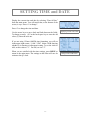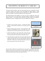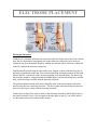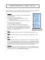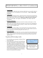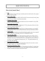
1
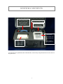
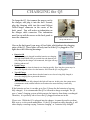
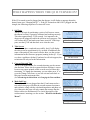
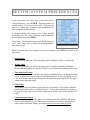
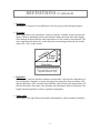
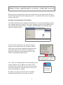
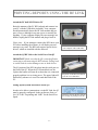
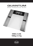
Quantum-III
User’s Manual
RJL Systems
33939 Harper Avenue
Clinton Township, Michigan
48035, U.S.A.
(800) 528-4513
(586) 790-0200
(586) 790-0205 (FAX)
-1-
Manual Revision Date:
August 29, 2007
-2-
TABLE OF CONTENTS
Intended Usage ............................................................................................................5
Indications for use
Intended Population
Contraindications
Warnings
Precautions
System Contents ........................................................................................... 6
Quantum-III Hardware ................................................................................. 7
Charging the Q3 ............................................................................................ 8
What Happens When Q3 is Turned ON? ..................................................... 9
Introducing the Main Menu .......................................................................... 10
Setting System Preferences .......................................................................... 11
Setting the Time and Date ............................................................................ 12
Testing the Subject Cables............................................................................ 13-14
Subject Preparation ....................................................................................... 15
Electrode Placement ..................................................................................... 16
Performing a BIA Test .................................................................................. 17-18
The Record Menu — Getting Results .......................................................... 19
BIA Questions ............................................................................................... 20-21
How do I measure frame size?
How is target weight calculated?
What do the different Activity Levels mean?
Definitions—What do the Results Mean? .......................................................... 22-23
Printing Reports Using the RF Link............................................................. 24-27
Sample Report……………………………………………………………..28
-3-
-4-
INTENDED USAGE
Indications for use
The Quantum-III measures or calculates the following values:
Resistance, Reactance, Impedance, Phase Angle, Body Fat* (FAT), Fat-Free Mass/Lean
Body Mass* (FFM/LBM), Total Body Water* (TBW), Intra-Cellular Water* (ICW), ExtraCellular Water* (ECW), Basal Metabolic Rate* (BMR), Daily Energy Expenditure* (DEE),
Body Mass Index (BMI)
* Estimated
Intended population / usage
The Quantum-III is intended to be used on normally healthy individuals aged 12-90, who
have not had an arm or leg amputated. It is not intended to diagnose or treat a disease or
medical condition.
Contraindications
No known contraindications exist.
Warnings
Bioelectrical Impedance Analysis (BIA) devices, like the Quantum-III, operate by introducing an alternating current (AC) signal into a body, and then detecting how that signal is affected by the body. This device should not be used on subjects with any implantable electronic devices such as pacemakers or implantable cardioverter defibrillators (ICDs).
Women who are tested with this device should not be pregnant or suspected of being pregnant. Besides increased inaccuracy of readings in this condition, the effects of the measurement on the fetus are unknown.
Precautions
Failure to follow the subject preparation and testing procedures (detailed on pages 15-16)
may result in incorrect readings.
The person performing the BIA tests must also be able to demonstrate proficiency in electrode placement. See page 15 for conducting a proficiency test.
-5-
SYSTEM CONTENTS
Pouch containing subject
cables and test resistor
Pouch containing Q3 charger
Adhesive Electrodes
( Behind Pouch )
Pouch containing USB
and serial cables
Quantum-III
Quantum-III RF Link
( Under Quantum-III )
Printer Charger
( Under Quantum-III )
Mini Thermal Printer
USB RF-Link
( Under Printer)
User manuals for the Quantum-III, Mini Thermal Printer, and PC Body Composition Software are not shown in
the picture above.
-6-
INTRODUCING QUANTUM-III HARDWARE
FRONT of Quantum-III
Power
Controls
Previous Field
( UP Arrow )
Next Field
( DOWN Arrow )
Battery Charging
Status Indicator
Multi-Purpose Serial Port
BACK PANEL of Quantum-III
Charger / Subject
Cable Port
-7-
Connects to:
• Mini Thermal Printer
• PC
• RF-Link
CHARGING the Q3
To charge the Q3, first connect the power cord to
the charger, and plug it into the wall. Second,
plug the charging cable into the round Subject
Cable/Charger connector in the center of the
back panel. You will notice an indentation on
the charger cable connector. This indentation
must line up with the arrow on the back panel to
insert the connector.
The indentation on the connector must
line up with the arrow.
Also on the back panel is an array of four lights which indicate the charging
status of the Q3. These lights will only turn on if the Q3 is plugged in. The
lights have the following meanings:
LOCATED
ON BACK
PANEL
•
Batteries OK
While the charger is plugged in and the batteries are charging,
this light should blink once per second. Once the batteries are
fully charged or the charger is disconnected, this light will stop
blinking and turn off.
•
Rapid Charge
This light turns on when the batteries are charging quickly. How long the system stays in
this mode depends on how low the batteries were when the Q3 was plugged in.
•
Top-off Charge
When the charging system detects that the batteries are close to being fully charged, it
slows the charging rate to protect the batteries.
•
Done Charging
Once the batteries are fully charged, this light will turn on. At this point, the system enters
a maintenance mode, and the batteries are monitored to ensure that they remain fully
charged.
If the batteries are low, it can take up to five (5) hours for the batteries to become
fully charged,. It is recommended the Q3 be allowed to charge overnight. The Q3
uses a “smart” charging system, which protects the batteries from being overcharged.
Therefore, it is perfectly safe to leave the Q3 plugged in when not in use.
Please note: While the Q3 is plugged into the charger, it cannot be used to perform
BIA tests or to do system maintenance. If the Q3 is turned on while charging, it will
either display a message saying “batteries charging” or “batteries fully charged”.
-8-
WHAT HAPPENS WHEN THE Q3 IS TURNED ON?
If the Q3 is turned on and is plugged into the charger, it will display a message about the
battery status (see “Charging the Q3”). If the Q3 is turned on and is NOT plugged into the
charger, the following sequence of events will occur:
1. Self Tests
The Q3 will begin by performing a series of self-tests to ensure
the internal circuitry is properly calibrated and working correctly.
This takes approximately 15-20 seconds. It is imperative the
charger not be plugged in while the self-tests are in progress. This
will confuse the Q3 and make some future tests fail. If this happens, turn the Q3 off and then back on to clear the error.
2. Title Screen
After the tests have completed successfully, the Q3 will display
the title screen for approximately five seconds. In addition to the
name of the analyzer, this screen will also show you the version
information for the firmware (program) running on the Q3. If you
ever have a problem with the Q3 and need to call tech support, the
technician will ask you for this information.
3. Current Date and Time
The Q3 will spend another five seconds showing you the current
date and time. Please check to ensure this date and time is correct
because any reports printed or BIA records saved will have this
timestamp. To change the timestamp, you can either press “0” to
go to the Change Time form, or you can wait and come back to
this page from the main menu later.
Performing self-tests
The title screen
Current Date and Time
(See Introducing the Main Menu and Changing the Time and Date.)
4. Main Info Page
If the subject cables are plugged into the Q3 and connected to a
test subject, this page will show the current measured resistance
and reactance; along with the calculated impedance and phase angle. Otherwise, this page will only contain the message that the
subject cables are disconnected. For a brief description of the
measurements’ meanings, see the section: “What Do the Results
Mean?”
Main page with subject cable connected.
Main page—subject cable disconnected
-9-
INTRODUCING THE MAIN MENU
Navigation through the program that runs on the Q3 is done by use of a couple of menus. To
get to the main menu, press the MENU key. When you do, the top four lines of the menu
will appear on the screen. For reference, the entire menu is shown below on the right. Use
the up and down arrows to move the blinking cursor through the list of screens. When the
cursor is next to the screen you want, press the ENTER key.
Here is a brief introduction to the various screens listed in the
main menu:
•
•
•
•
•
•
•
Main Page
You were introduced to the main page in the previous section.
This screen shows you either the BIA readings currently being
measured (if cables are currently connected to the patient) or
the message saying the cables are disconnected.
Time & Date
This screen is shown briefly when you turn on the Q3. It displays the current time and date which will be printed on reports or saved on BIA records. This screen provides the opportunity to update the Q3’s system clock.
Subject Input
This screen is used to enter patient data to calculate body composition. Once all of the necessary data has been inputted,
you will have the opportunity to view body composition results and print reports.
Edit Preferences
The preferences screen allows you to configure the behavior
of the Q3. You can set units for height and weight, time and
date formatting, etc.
Storage Status
The Q3 is capable of temporarily storing 110 body composition test records in its memory. Records saved on the Q3 are
preserved (even when it is turned off) until they are
downloaded into a program on a PC. Going to this screen will
show you how much space remains in the memory.
Run Self Tests
Selecting this menu option will re-run all of the tests that are
performed every time the Q3 is turned on.
About
This menu option takes you to the title page that you were introduced to in , “What Happens When the Q3 is Turned
On.”
- 10 -
The Main System Menu
SETTING SYSTEM PREFERENCES
In the main menu, move the cursor to the field next to
“Edit Preferences”; press ENTER. Selected options are
marked with an ‘X’ to the left of the field. Shown on the
right, the 24-hour time formatting and Month/Day/Year
date formatting are both selected.
To change a setting, (for example, to set 12-hour AM/PM
formatting) move the cursor to the left of the field of the
desired option and press ENTER
Please note: The communications speed should always be
set to “9600” unless you are using custom-designed hardware with your Q3.
The System Preferences Form
When all options have been changed to the desired settings, press MENU to return to the
main menu.
•
Height Units
Tell the Q3 whether you will be entering people’s heights in inches or centimeters.
•
Weight Units
Tell the Q3 whether you will be entering people’s weights in pounds or kilograms.
Results that are weights (i.e. amount of fat) are also formatted according to this setting.
•
Time and Date Format
These settings control how the date and time gets formatted when it is displayed on the
screen or printed on a report using the mini thermal printer. If you are printing via a PC
Link, how the date and time get formatted will depend on the settings of the PC application used to print the report.
•
Print Using
This setting is used to format a report which is to be printed. If you will be using the
mini thermal printer, select “Attached Printer”. If you will be printing via a program
on your PC using either a direct cable connection or the RF Link, set the option to “PC
Link”.
•
Communications Speed
This setting allows you to select one of two different data rates. HOWEVER, unless
you are connecting the Q3 to a custom piece of hardware or software which specifically requests the higher setting, you should always leave this setting on 9600.
- 11 -
SETTING TIME and DATE
Display the current time and date by selecting “Time & Date”
from the main menu. You will notice that, at the bottom of the
screen, it says “Press ‘0’ to change”.
Press ‘0’ to change the time and date.
Displaying current time & date
Use the arrow keys to move back and forth between the fields.
To change an entry: (1) Use the back-space key to erase the old
value; (2) Enter the new one.
If you are using 12-hour AM/PM time formatting, you will see
in the upper-right corner, “1 AM / 2 PM” below a field showing
whether it is morning or afternoon/evening. To set the clock to
AM, set this value to “1”. For PM, set it to “2”.
When you are satisfied with the time settings, press MENU to
return to the main menu. The settings on this form will now be
written to the Q3 clock.
- 12 -
Change Time & Date Form
TESTING SUBJECT CABLES
The subject cables are delicate. Abuse can cause breaks in the wires. Frequently, this leads
to incorrect resistance and reactance values and readings that rapidly change or “jump
around”. Be careful not to tie them in knots or to fold them over. When storing the subject
cables, they should be coiled loosely and placed in their storage pouch.
The cables should be tested regularly or any time you receive readings that “don’t look
right.” RJL Systems receives calls from new customers asking how regularly we recommend
testing the cables. A set of subject cables should last a long time, if they are used gingerly
and treated with respect. Testing them once every few months is not a bad idea.
1. Navigate to the main page of the Q3. Assuming the subject
cables are disconnected, you should see the message shown to
the right.
[1] Cables are Disconnected Message
on the Main page
2. Connect the subject cables to the Q3. On the round subject cable
connector, the indentation must line up with the arrow on the
back panel of he Q3 to allow proper insertion of the connector.
3. Take the test resistor out of its storage tube. Connect the clips
from one of the cables to the wire on one side of the resistor.
The red clip must be between the black clip and the resistor.
4. Connect the other two clips to the wire on the other side of the
resistor in the same manner. It does not matter which cable gets
connected to which wire—the test resistor cannot be connected
“backwards”. What matters is that both clips from the same cable get connected to the same side of the resistor.
[2] The indentation on the connector
must line up with the arrow.
[3] - [4] The subject cables properly
connected to the test resistor
Once the subject cables have been connected to the test resistor, you should see the screen
change to show you the current resistance, reactance, impedance, and phase angle. These measurements may appear before all four clips are connected to the resistor, but it is imperative that
all four clips do get connected before proceeding with the test.
- 13 -
TESTING SUBJECT CABLES (Continued)
The resistance value should read almost exactly 500 Ohms. Readings of 499 or 501 are
acceptable. Now, gently move the cables around while watching the screen of the Q3 for
any large changes in the resistance value. Changes of +/-2 Ohms in resistance while you
are moving the cables around are acceptable. Changes of 10 Ohms or more are not. If you
see large changes in the resistance readings, then your cables are damaged and need to be
replaced before you perform any BIA tests. Please call RJL Systems to order a new set.
The Cables are Disconnected Message on the
Main age
- 14 -
SUBJECT PREPARATION
ELECTRODE PRECAUTIONS
Before testing any patients and collecting date from BIA tests, it is highly recommended that
the specialist demonstrate a proficiency in electrode placement. This proficiency is proven
by the specialist conducting two consecutive tests on the same subject and receiving results
which differ from each other by less than one percent (1%).
Proficiency Test
1. Connect all four electrodes to the subject and attach the subject cables. Note the resistance and reactance values on the main page.
2. Disconnect the cables and remove and discard the electrodes.
3. Repeat steps (1) and (2) with a fresh set of electrodes.
4. To demonstrate a proficiency, the values from the two tests should differ by less than one
percent (1%).
Subject Preparation
•
•
•
•
•
•
•
•
•
The person being tested should not have exercised or taken a sauna within 8 hours of the
study.
The person being tested should refrain from alcohol intake for 12 hours prior to the
study.
The person being tested height and weight should be accurately measured and recorded.
The person being tested should lie quietly during the entire test.
The person being tested should not be wet from sweat, and any lotion on the hand and
foot must be removed with an alcohol swab.
The person being tested should not have a fever or be in shock.
The study and testing procedure should be explained to the person being tested .
The exam area should be comfortable, and free of drafts.
The exam table surface must be non-conductive, and be large enough for the person being tested to lie supine, with the legs not in contact with each other, and the arm at an approximate 30° angle to the body.
- 15 -
ELECTRODE PLACEMENT
Placing the Electrodes
The BIA test is normally performed on a person’s right side. Either side of the body could be
used, but it is important to consistently test on the same side of the body for all tests performed on any given individual. Begin by making sure that the subject cables are connected
to the Q3, and that the analyzer is turned on.
Find the ulnar head by feeling the joint of the wrist. Imagine or draw a line bisecting the ulnar head, perpendicular to the arm. Place the hand detecting electrode proximal (on the hand
side) to this line, with the tab of the electrode pointing away from the body. The hand’s signal electrode should be wrapped around the middle finger, with the tab facing away from the
body, which should put it inline with the detecting electrode.
The medial mallealus (inside ankle-bone) should be used in the same manner as the ulnar
head to place the foot’s detecting electrode. The foot’s signal electrode should be placed at
the base of the big toe, inline with the detecting electrode.
Connect the red clips of the subject cables to the detecting electrodes, and the black clips to
the signal electrodes. Now, if you navigate to the main page on the Q3, you will be able to
see the current measured resistance and reactance.
- 16 -
PERFORMING A BIA TEST
Select “Subject Input” from the main menu. The top four lines of this page are shown on the
right. Here is a brief rundown of what the input fields are asking for:
•
Subject ID
This field is used by your computer to be able to differentiate one
patient from another.
•
The Subject ID field is REQUIRED if:
1) You will be saving the test record on the Q3 to be later
transmitted to your PC or
2) You will be using the RF link to print reports from your PC.
•
The Subject ID field is OPTIONAL if:
1) You do not plan to save the tests or
2) You are not going to use the RF Link to print reports.
•
An example of a setting where you might not want to save the reports would be if you were performing BIA tests at a health fair,
where you were seeing large numbers of people whom you did
not expect to see as long-term clients.
The Subject Input Form
•
Height
The patient’s height, in whichever units were selected in the “Edit Preferences” form.
•
Weight
The patient’s weight, in whichever units were selected in the “Edit Preferences” form.
•
Age
The patient’s age.
•
Gender
To enter the patient’s gender, enter ‘1’ if the person is male, ‘2’ if the person is female. If
the patient has undergone surgery for gender reassignment, it is important to enter the patient’s original gender at birth. Men and women are genetically programmed to distribute
fat throughout the body differently, and these differences in distribution need to be compensated for by the Q3 when the resistance and reactance values are analyzed.
•
Frame Size
The Q3 will adjust its calculation of the patient’s target weight based on their frame size.
Enter ‘1’ for a small frame, ‘2’ for a medium frame, and ‘3’ for a large frame. For detail
on measuring frame size, see How do I measure frame size?
- 17 -
PERFORMING A BIA TEST (Continued)
•
Target Weight
You may choose to either enter your own target weight value, or you can allow the Q3 to
calculate one for you. The method the Q uses is described in: “How is target weight
calculated?”
•
Activity Level
The activity level field gives the Q3 a general idea of how much activity the patient regularly sees as a result of his/her average daily routine. For descriptions that might help you
choose which activity level to select, see What do the different activity levels mean?
Enter 0 for “Very Light”, 1 for “Light”, 2 for “Moderate”, 3 for “Heavy” and 4 for
“Exceptional”.
•
Resistance & Reactance
You may choose to either manually enter values for resistance and reactance, or if the
subject cables are currently connected to the patient, you can have the Q3 automatically
fill in the currently measured values by pressing ‘0’ with the cursor on the field labeled
“Press ‘0’ here to read BIA values:”
•
Save Record?
You may choose to answer either yes or no to this question. To proceed to the Record
Menu and get the test results without saving the record, press Enter with the cursor next
to ‘no’. To save the record before getting the result, answer ‘yes’.
•
Exit to Main Menu
Once you are in the Subject input form, you can not exit back to the main menu by pressing the “Menu” key. This is to prevent you from accidentally exiting from the form and
losing your inputted data. To exit back to the main menu, place the cursor on this field
and press Enter.
To perform a BIA test and get results:
1. Fill in all fields except, optionally, the Subject ID and
target weight fields
2. Answer either YES or NO to the “Save Record” question. If any field contains a value outside of an allowable range, or if there are any other problems, a message will be displayed describing the error, and you
will be taken back to the subject input form and given
an opportunity to correct the error. If there are no problems and you answered “Yes”, then you will be briefly
shown a message telling you how many records are
saved on the Q3 (including the one you just entered)
before you are taken to the record menu.
- 18 -
If the record is saved, the
storage status is shown before going
to the record menu.
THE RECORD MENU — GETTING RESULTS
Once you have entered the subject record and answered either ‘yes’ or ‘no’ to the Save
Record question, you will be brought to the record menu, which is shown to the right.
•
Edit Record
To go back to the Subject Input form to review the data you
inputted, or to make changes, select this option.
•
View Results
Selecting this option takes you to the results screen. (shown
below) You will be able to scroll up and down through the
list of calculated results with the up and down arrow keys.
While in the results page, pressing the menu button will
bring you back to the record menu.
•
Print Report
Selecting this option will send the report to be printed. How
it gets sent depends on how printing was configured in the
preferences screen. If “Attached Printer” was selected in the
preferences, then the Q3 will assume that the mini thermal
printer is attached to the Q3’s serial port, and will format the
report layout accordingly. If “PC Link” was selected, then
the Q3 will assume that the serial port on the Q3 is either
connected to an RF Link with your PC, or is directly connected to your PC with a serial cable.
•
Enter New Record
If you are done with this test, but have another to enter, select this option.
•
Exit to Main Menu
If you are done viewing results and printing reports for this
test, and have no more tests to enter select this option to return to the main menu.
The Record Menu
The Results Page
- 19 -
BIA QUESTIONS
How do I measure frame size?
There are two methods for measuring frame size:
•
The Precise Method
First, measure the patient's height. Next, use a measuring tape to measure the circumference of the patient's wrist. (make sure to use the same units for both measurements. Do
not mix inches and centimeters.) Divide the height by the wrist circumference. If the result is greater than 10.4, the patient has a small frame. If it is less than 9.6, the patient has
a large frame. Otherwise, the patient has a medium frame.
•
The Easy Method
A simpler, albeit less precise, method is to have the patient wrap the thumb and forefinger of one hand around the wrist of the other hand. If the thumb and forefinger overlap,
the person has a small frame. If the tips of the thumb and forefinger touch, the person has
a medium frame. If there is a gap, the person has a large frame.
How is target weight calculated?
On the subject input form, you can choose to either enter in your own value for target
weight, or you can allow the Q3 to calculate one for you. The formulas that the Q3 uses to
calculate target weight are called the “Hamwi Ideal Weight Equations” which are as follows:
•
For Males
Target weight = 106 + 6 x ((height in inches) - 60)
•
For Females
Target weight = 100 + 5 x ((height in inches) - 60)
Once you have a target weight, if the patient has a small frame, adjust it for the patient’s
frame size. If the patient has a large frame, add 10% to get the final value. If the patient has a
small frame, subtract 10%.
- 20 -
BIA QUESTIONS (Continued)
What do the different Activity Levels mean ?
Basal Metabolic Rate (BMR) is an estimate of how many calories your body would burn in a
24 hour period if your body were completely at rest. To get an idea of how many calories
your body actually requires in a day, select the activity level that best describes how you
spend the majority of your day. ( > 12 hours / day ) Under each label below is a list of representative activities to help you choose the most appropriate activity level.
Earlier body composition analysis software from RJL Systems used different labels for the
activity levels, which are listed in parenthesis.
•
Very Light
( No Exercise )
Seated and standing activities, painting, driving, laboratory work, typing, sewing, ironing, cooking, playing cards, playing a musical instrument
•
Light
( Some Exercise )
Walking on a level surface at 2.5 to 3 miles per hour ( 4 - 4.8 kilometers per hour ), garage work, carpentry, restaurant trades, house-cleaning, child care, golf, sailing, table
tennis
•
Moderate
( Moderate Exercise )
Walking 3.5 to 4 miles per hour ( 5.6 - 6.5 kilometers per hour ), weeding and hoeing,
carrying a load, cycling, skiing, tennis, dancing
•
Heavy
( Athletic )
Walking with a load uphill, tree felling, heavy manual digging, basketball, climbing,
football, soccer
•
Exceptional
( Elite Athlete )
Extremely strenuous physical activity
- 21 -
DEFINITIONS
What do the Results Mean?
•
FAT
Fat is the energy storage of the body. Everybody needs fat in their bodies, but it is important not to have too much.
•
Fat Free Mass (FFM)
This value is, literally, what would be left after all fat was removed from the body. Many
people also refer to FFM as Lean Body Mass (LBM).
•
Total Body Water (TBW)
Literally, the total amount of water in the body. Since fat is essentially 0% water, TBW
is entirely contained within FFM.
•
Intra-Cellular Water (ICW)
“Intra-Cellular” literally means, “Within the cell”. This is the portion of the water in the
body that is contained inside the cells.
•
Extra-Cellular Water (ECW)
This is the portion of water in the body that is not contained within the cells. Examples
of where ECW normally occurs include blood plasma, joint fluid, and bladder contents.
•
Target Weight
If you and your patient know how much he/she should weigh, this value can be manually
entered. Otherwise, it is calculated using a set of standardized formulas.
•
Body Mass Index (BMI)
A person’s BMI is equal to their weight in kilograms divided by their height in meters,
squared. BMI is commonly used as an indicator of whether someone is overweight. It is
important to note, however, that somebody who is “overweight” may not necessarily be
“over-fat”. A 5’10”, 300 pound couch potato and a 5’10”, 300 pound bodybuilder will
have exactly the same BMI.
•
Basal Metabolic Rate (BMR)
Basal Metabolic Rate is the number of calories that a person will use per day, by virtue
of simply being alive (i.e., lying still and breathing).
•
Daily Energy Expenditure (DEE)
People generally do not lay in bed all day, doing nothing but breathing. To estimate how
many calories a person actually burns in a day, the program will adjust the BMR based
on what you entered as the person’s daily activity level.
- 22 -
DEFINITIONS (Continued)
Resistance
Resistance is a measure of how difficult it is for electricity to flow through an object.
•
Reactance
Most objects have some capacitance, which is a measure of ability to store an electrical
charge. When an alternating current (periodically changes direction, like a BIA signal)
flows through an object that has some capacitance to it, the current is slowed down. The
more capacitance the object has, or the faster the current changes direction, the less the
object will “react” to the current.
nce
a
d
e
Phase
Imp
Angle
Reactance
•
Resistance
Diagram showing the relationship
between Resistance, Reactance,
Impedance and Phase Angle
•
Impedance
RJL Systems’ analyzers measure resistance and reactance, which are the component vectors of impedance. Imagine, on a map, drawing a line going East from your house. Call
this line Resistance. Now, from the end of that line, draw a shorter one going North. Call
this line Reactance. Now draw a line from the end of Reactance back to your house. The
length of this diagonal line is what is reported as impedance.
•
Phase Angle
Phase angle is the angle between resistance and impedance, and is measured in degrees.
- 23 -
PRINTING REPORTS USING THE RF LINK
Before you can use the RF Link to print reports from your Q3, you must have the RJL Systems Print Monitor installed and running on your PC. You must also have the Q3 configured
to print via the Link.
Installing and Launching the Print Monitor
Use either of these shortcuts to launch the Print Monitor. You will know that the print monitor is running when you see the RJL icon in your computer’s System tray. In addition to letting you know that the print monitor is running, right-clicking the icon will bring up the
menu for changing settings
Desktop Shortcut and Start Menu entry for the Print Monitor
If you have received software with your Q3, the print
monitor will be installed when you install the software.
Please follow the software installation instructions in the
software manual. Once the software is installed, you
should have shortcuts on your desktop and in the Start
Menu for launching the Print Monitor.
The RJL icon in the system tray shows
the Q3 printing monitor is running and
the printing monitor’s menu.
Note: If you are running Windows XP, depending on your
settings, Windows may be hiding some of the icons in
your system tray. If that is the case, you will see an arrow
icon in your system tray. Click this icon to be able to see
the icons that Windows is hiding.
By default, once the print monitor has been installed,
it should automatically start every time you log in.
- 24 -
Clicking this icon
will show you all of
the icons that Windows has hidden in
your system tray.
PRINTING REPORTS USING THE RF LINK
Attach the PC half of RF Link to PC
Raise the antenna of the PC RF Link unit and connect it to
your PC with the USB cable (included). Your computer
should automatically detect the RF Link module and prepare it for use, although it may not appear to actually do
anything. If your computer displays an error message in a
bubble, unplug the RF Link module and plug it back in.
Please note: If you attempt to connect the RF Link to your
PC before installing the software, it will display an error
message every time. The RF Link requires special device
drivers, which are installed with the software.
The PC RF Link unit, which attaches
to your computer with a USB cable.
Attach the Q3 RF Link to the Serial Port of the Q3
IMPORTANT: Make sure that the Q3 is turned off before
connecting or disconnecting the RF Link unit. Failing to do
so could result in serious damage to one or both devices.
The Q3 portion of the RF Link plugs into the serial port on
the back of the Q3. When the Q3 is turned back on, the
Light at the bottom will turn on to show that it is connected
properly and that it is receiving power. The upper light will
flash briefly whenever it is used to send data back to the
PC.
This portion of the RF Link connects
to your PC via a USB cable.
Setting up the System Preferences on the Q3
In order to be able to communicate via the RF Link, the Q3
must be properly configured. In the preferences form, select “PC Link” for printing and “9600” for the Serial Port
Speed.
- 25 -
Preferences form on the Q3, showing
the settings for printing via the PC
PRINTING REPORTS USING THE RF LINK
Setting up the Print Monitor for the BIA Software
Before the print monitor can be used to print reports from the Q3, it has to be configured.
Two different groups of settings may need to be adjusted in the print monitor. “Print Settings” control how the print monitor interacts with the BIA software on your PC. “Serial Settings” control how the print monitor communicates with your Q3.
Configuring Print Settings
Right-click on the system tray icon for the
print monitor and select “Change Print Settings”. The window to the right will appear.
After installation, the printing program and
printing command should already be set correctly. Here is a rundown of what the settings
mean:
The Print Settings window for the Q3 Print Monitor
•
•
•
•
Printing Program—This is the program that will be used to print the report. This should be set to
the location of the main program file for the body composition software on your PC.
Printing Command—This command is sent to the above program, along with the data and remaining settings, to tell it to print. Please reference the manual for your PC body composition
software to ensure that this setting is correct.
Database—Before printing a report, the record will first be saved to this database. This field must
contain the complete location to a valid database. Otherwise, the report will not print. Once you
have created a database in your PC body composition software, you will want to change this
value to ensure that the records from the Q3 are placed in the appropriate database.
Quick Report—This is the name of the layout that will be used by the PC to print the report. If
you create a new Quick Report layout in your PC software, you may change this setting to use the
new layout.
You will likely want to change the Database and Quick Report settings. For more detailed information and to verify what values to put in the “Printing Program” and “Printing Command”, see the
manual for your PC body composition software.
- 26 -
PRINTING REPORTS USING THE RF LINK
Configuring Serial Settings
In addition to specifying the program and settings to use to
process the report to be printed, serial port settings must be
configured so that the Quantum-III can communicate with
your PC. In general, every setting (except for Port) should
be set as shown on the left. To get to this window, select
“Change Serial Settings” from the Print Monitor’s menu.
The Port drop-down menu will list all serial ports (also
known as COM ports) identified on your computer. Many
computers will skip port numbers, so identifying which
port to use may initially be difficult. One rule of thumb to follow is that if using a regular serial cable
to connect to the unit, you will likely want to select a port in the COM1 - COM4 range. If there is a
USB cable involved, such as if you are using the RF Link to print wirelessly, the port you want will
most likely be COM5 or higher.
Note that the Port drop-down box is grayed-out in the picture above. This means that the port is currently open, and cannot be changed. If this occurs, close the port from the monitor’s menu before going to “Change Serial Settings”, make the desired changes, and then reopen the port.
The Print Monitor MUST have a port open in order to communicate with the Quantum-III.
If you try printing a report from your Q3 and nothing happens, verify that the port is open. If so, try
closing the port, selecting a different port, and then opening it.
When Not to use the RF-Link
The RF-Link may only be used for printing the current test record with the PC body composition
software. When downloading multiple records to the PC application’s database or printing via the
mini thermal printer, the Q3 must be directly connected to the computer or printer with a cable.
Attempts to use the RF Link to download multiple records will generate errors.
- 27 -
Sample Report
════════════════════════════════════════
Date:08/29/2007
ID# :2
Age:
Height:
Weight:
Frame Size:
Time: 12:04:17
Eq Set: NHANES-III
31.0 years
Sex: Female
65.0 IN Resistance: 599.5
120.0 LB Reactance: 63.5
Medium
Impedance: 602.9
Phase Angle: 6.0
Body Mass Index (BMI) :
Target Weight :
Target Fat Range % :
Target weight based on
Target Fat Range :
A sample report from the included mini thermal printer is shown
to the left, reduced to 2/3 of normal size. If the individual’s body
fat percentage is within 3% of the “Target Fat Range” or below,
the “Recommendations” section of the report will not print.
Reports from the Quantum-III can also be printed through additional body composition software on a PC. For samples of those
report layouts, see the documentation for the PC software.
20.0
125.0
19.1 - 24.1
111.3 - 118.7
═════════════ Metabolism ═══════════════
Basal Metabolic Rate (BMR): 1329.1
Daily Activity Level: Very Light
Daily Energy Expend. (DEE): 1727.9
══════════ Body Composition ════════════
Mass
% of
weight
Fat
(FAT): 29.9
24.9
Fat Free Mass (FFM): 90.1
75.1
══════════ Fluid Composition ═══════════
Litres % of
weight % of
Total Body
(TBW): 30.4
55.8 TBW
Intra-Cellular(ICW): 16.2
29.8 53.4
Extra-Cellular(ECW): 14.1
26.0 46.6
═══════════ Recommendations ════════════
It is recommended that you lose
5.1 LB of body fat. The maximum rate
of fat loss that is generally
considered safe is 2.0 LB /week. At
this rate, it should take approx.
2.56 weeks to reach your target.
Based on your daily activity level,
it is estimated that you require 1728
calories of food to keep your weight
stable. To lose 2.0 LB per week
through diet alone, you would have
to reduce your food intake to 728
calories per day. If, on the other
hand, you were to exercise regularly,
you would not need such a restrictive
diet to achieve the same rate of
weight loss.
If your exercise program is done
consistently, (every other day) then
your BMR and daily energy expenditure
will improve, thereby increasing the
efficiency of burning calories.
Ideally, most of the weight you lose
will be fat. It is normal to lose
some excess water, especially during
the initial phase of your diet and/or
exercise program. This may cause
fluctuations in your Total Body Water
and Fat Free Mass. A regular exercise
exercise program will increase your
Fat Free Mass and decrease Body Fat
throughout your weight loss program.
════════════════════════════════════════
- 28 -