1
Instructions for installation and use
English
EN
FR
EN
More languages on:
www.zodiac-poolcare.com
H0369400.B - 2013/03
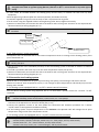
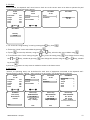
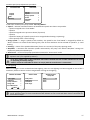
Read this notice carefully before installing, maintaining or repairing this appliance! The symbol indicates important information that it is imperative to take into consideration in order to avoid all risks of harm to persons or damage to the appliance. The symbol indicates useful information. Warnings As part of the continuous improvement process our products may be modified without prior notice. Exclusive use: centralised pool control system (must not be used for any other purpose). The appliance must be installed by a qualified technician, in compliance with the manufacturer's instructions and in compliance with current local standards. The installer is responsible for the installation of the appliance and the compliance with local regulations in matters of installation. Under no circumstances can the manufacturer be held liable in the event that local installation standards are not respected. It is important that this appliance be handled by skilled and apt persons (physically and mentally) having received the instructions for use beforehand (through reading these instructions). All persons not meeting these criteria must not approach the appliance in order to avoid exposure to dangerous elements. If the appliance suffers a malfunction: do not try to repair the appliance yourself, contact your installer. Before working on the appliance, make sure it is powered off and that all equipment connected to it is powered off. Before all connections, make sure that the voltage indicated on the plate on the appliance corresponds to the mains voltage. Eliminating or shunting any safety devices automatically voids the warranty, as does the replacement of parts using parts not originating from our warehouses. Wrong installation or use may cause serious damage to property or serious injuries (possibly causing death). Keep the appliance out of the reach of children. H0369400.B.EN – 2013/03 1 Contents 1. Information before installing ................................................................................... 2 1.1 General delivery terms................................................................................................................................. 2 1.2 Contents ....................................................................................................................................................... 2 1.3 Technical specifications ............................................................................................................................... 3 2. Installation ............................................................................................................... 3 2.1 Installing the AquaLink TRi® control box ..................................................................................................... 3 2.2 Installing the remote user interface ............................................................................................................ 4 2.3 High voltage electric connections ................................................................................................................ 4 2.4 Low voltage electric connections ................................................................................................................. 5 2.5 Connection to a heating system .................................................................................................................. 6 2.6 Connections to the iAquaLinkTM antenna‐box ............................................................................................. 7 2.7 Connecting an iAquaLinkTM compatible appliance ...................................................................................... 8 3. User interface settings ............................................................................................. 8 3.1 Enclosure user interface presentation ......................................................................................................... 8 3.2 Home screens ............................................................................................................................................... 9 3.3 Initial and current settings ........................................................................................................................... 9 3.4 Equipment settings .................................................................................................................................... 11 3.5 Advanced settings ...................................................................................................................................... 14 3.6 Wireless User Interfaces ............................................................................................................................ 19 4. Operational safety ................................................................................................. 20 4.1 Heating cooldown timer ............................................................................................................................ 20 4.2 Heating start‐up timer ............................................................................................................................... 20 4.3 Heating regulation timer ............................................................................................................................ 20 4.4 Filtering timer with JVA valves ................................................................................................................... 20 4.5 Cleaner lock ................................................................................................................................................ 20 4.6 Anti‐Freeze safety ...................................................................................................................................... 21 5. Maintenance .......................................................................................................... 21 5.1 Maintenance instructions .......................................................................................................................... 21 5.2 Available accessories ................................................................................................................................. 21 5.3 Recycling .................................................................................................................................................... 21 6. Registering the product .......................................................................................... 21 1. Information before installing 1.1 General delivery terms All equipment, even postage and packing paid, travels at the risks and perils of the recipient. Written reserves should be made on the transporter's delivery documents if damage during transport is discovered by the recipient (confirmed by registered letter to the transporter within 48 hours). 1.2 Contents AquaLink TRi® control box H0369400.B.EN – 2013/03 iAquaLink antenna‐box + USB cable + quick start guide Water temperature sensor 2 Cable gland* Plastic cover + metal RJ11 cable extension Hardware for the Air temperature support for offsetting for offsetting the user AquaLink TRi® sensor fixing clip the user interface interface (5 metres) control box *Use the supplied cable glands to pass all the wires inside the control box in order to maintain the protection index. Remove the removable caps from the metal base of the AquaLink TRi® control box to insert the cable glands. 1.3 Technical specifications AquaLink TRi® control box Size (l x h x d) 36.5 x 30.5 x 13.5 cm Weight (complete appliance) 3.5 kg Protection index IPX5 Power supply 220‐240 V AC / 50 Hz Consumption 200 W / 0.9 A 0 – 240 V AC / 25 A Relay specifications per relay Relay power equivalences 3 HP / 1500 W iAquaLink™ antenna box Size (h x l; excluding the antenna) Power supply Web connection WiFi network specifications 15.0 x 10.5 cm RS485 10 V DC, 180 mA WiFi or wired (Ethernet RJ45)
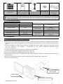
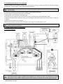
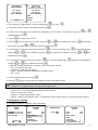
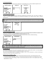
802.11b Open or secure, WEP or WPA encryption 2. Installation 2.1 Installing the AquaLink TRi® control box The AquaLink TRi® control box is ideally located in a technical room or outside in a sheltered location, and is imperatively close to the pool equipment to be controlled, and sheltered from frost, and easily accessible at any time, it must be installed at a minimum distance from the edge of the pool in order to avoid any projections of spray onto the appliance. This distance is determined by the electric standards applicable locally (In France: 3.5 metres) It must be installed on a level, ideally at 1.5 metres from the ground, use the control box fixture support to drill 4 holes in the wall, fix the support using the supplied plugs and screws (see §1.2), open the control box cover (2 screws on the right side) and drill the hole in the side of the control box (see diagram below). place the control box and screw it onto the support using the supplied "M5" type screws. close the control box cover. Wall fixture support and hardware "M5" screws H0369400.B.EN – 2013/03 AquaLink TRi® control box 3 2.2 Installing the remote user interface The user interface can be offset if access to the control box is not easy, to do this use the user interface offset kit (plastic cover + metal support + RJ11 cable extension, see §1.2). This operation must be carried out before connecting the appliance to the electric power supply (powered off). use the user interface control box fixture support to drill 2 holes in the wall, fix the support using plugs and screws (not supplied), open the box cover (2 screws on the right side), unscrew the user interface from the control box cover, and disconnect the installed RJ11 cable, connect the supplied RJ11 extension cable, pass it through a cable gland (small model) and connect it to the user interface, place the user interface on its support, fill the user interface housing on the control box cover using the supplied plastic cover. If you need more than 5 metres of cable, purchase an RJ11 telephone cable of the required length from a retailer (50 meters maximum). 2.3 High voltage electric connections iAquaLink™ antenna‐box 2.3.1 Wiring diagram User interface
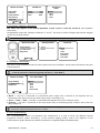
"RCD" (= Residual Current Device): ground fault protection device. Each electric power supply arriving at the AquaLink TRi® control box must be protected by a 30mA ground fault circuit breaker and by a specific circuit breaker or protective fuse of the appropriate size. H0369400.B.EN – 2013/03 4 2.3.2 Power supply connection to the AquaLink TRi® control box The AquaLink TRi® control box has its own power supply. It must be permanent and protected by a 30 mA ground fault circuit breaker. Please refer to the wiring diagram §2.3.1. The use of a 30 mA Residual Current Device with a manual switch (= RCD) is mandatory to protect the AquaLink TRi® mains supply. It must be accessible at any time by anybody who needs to access to the unit. 2.3.3 Connection to the filtering pump relay On the "FILTER PUMP" relay connect: the permanent power supply to terminals 'Line 1" (live) and "Line 2" (neutral). This power supply must be protected upstream by an appropriate ground fault circuit breaker and fuse. the power supply cable for the filtering pump to terminals "Load 1" (live) and "Load 2" (neutral). 2.3.4 Connecting auxiliary equipment Connect to relays "AUX1", "AUX2" and "AUX3": the permanent power supply to terminals 'Line 1" (live) and "Line 2" (neutral). This power supply must be protected upstream by an appropriate ground fault circuit breaker and fuse. the power supply cable for the equipment to be controlled to terminals "Load 1" (live) and "Load 2" (neutral). The "AUX1", "AUX2", and "AUX3" relays are free to be used to control any electric equipment compliant with the capacities shown on the wiring diagram §2.3.1 (for example a booster pump, a lighting transformer, an extra pump for a water feature or a backwash, garden lighting, etc.) Do not connect multiple items of equipment to the same relay. The relays can also be used as switches for equipment with an external electric power supply that only require a low voltage "on‐off" contact command. In this case only use one side of the relay: "Line 1" / "Load 1" or "Line2" / "Load 2". 2.4 Low voltage electric connections Low voltage connections have a reserved area on the right of the AquaLink TRi® control box. You can connect: - 1 air temperature sensor (installed at the base of the control box) - 1 water temperature sensor (supplied) - 1 "RS485" cable from the iAquaLink™ antenna‐box (supplied) And optionally (not supplied): - 1 solar temperature sensor - 1 heating system control cable - 1 "RS485" TRi® salt water chlorinator control cable - 1 "RS485" cable for any other iAquaLink™ compatible equipment 2.4.1 Air temperature sensor connection The air temperature sensor is pre‐wired and placed at the base of the AquaLink TRi® control box. It is imperative that it measures outside air temperature, and it must be sheltered. If the control box is installed inside, the temperature sensor must be installed remotely: - remove the sensor from the control box with its 5 metre cable, - fix the sensor outside, under a shelter, using the supplied fixture clip. The air temperature sensor is especially useful in managing the anti‐freeze safety device. Zodiac® cannot be held liable for damage caused to the pool related to the incorrect location of the air temperature sensor. 2.4.2 Water temperature sensor connection A sensor is designed to measure water temperature and control the pool water heating system. It is supplied with a 5 metre cable (see §1.2). The water temperature sensor must measure the temperature before the heating system. H0369400.B.EN – 2013/03 5 Before installing the sensor, make sure that the filtering is stopped and that the valves are shut. It is designed to be fitted to rigid PVC piping Ø50 mm, Ø63 mm or Ø1 ½’’. Do not install on any other type of piping. it must either be installed between the filtering pump and the filter, or between the filter and any other equipment, drill the pipe using a Ø9 mm (Ø10 mm maximum) drill bit, then deburr the hole, install the supplied O‐ring on the sensor body so that is is positioned in its groove. fix the sensor using the supplied stainless steel tightening collar. Do not tighten excessively. position its cable neatly and connect the end to terminals 5 and 6 of the green connector on the AquaLink TRi® electronic board (see wiring diagram §2.3.1). There is no connection polarity for the sensor connection. It can be shortened if necessary, but not extended. Sensor "O‐ring" seal
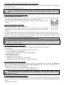
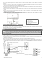
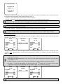
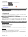
Stainless steel 2.4.3 "Solar priority" sensor connection The AquaLink TRi® can be fitted with an extra water temperature sensor to manage a solar heating priority if the pool is fitted with one. This extra sensor is not supplied (the required model is the same as the original water temperature sensor), see §5.2. The sensor must be in the immediate proximity of the solar heating system to be able to measure a coherent temperature. to install it, proceed in the same way as for the water temperature sensor (see §2.4.2). position its cable neatly and connect the end to terminals 3 and 4 of the green connector on the AquaLink TRi® electronic board (see wiring diagram §2.3.1). 2.5 Connection to a heating system AquaLink TRi® is compatible with al types of pool heating: heat pump, heat exchanger and electric warmer. Thanks to its built‐in water temperature sensor, it can manage set point temperatures and thereby only start the heating when needed. 2.5.1 Heating system equipped with a « on/off » remote control connector You can drive a heating system using AquaLink TRi® if it is fitted with a specific contact for a remote '"on‐off" command. Examples of compatible heating systems: Zodiac® EdenPAC, Power First Premium, Power Force, etc... heat pumps. Connect a 2 x 0.75 mm² electric wire (not supplied) of the appropriate length to terminals 1 and 2 on the green connector of the AquaLink TRi® electronic board (see §2.3.1), connect the appliance contact to the wire (follow the connection and activation procedure for a remote "on/off" switch in the appliance installation manual), set the heating system set point temperature to the maximum. The AquaLink TRi® will manage the set point temperature using its own water temperature sensor. 2.5.2 Heating system not equipped with a « on/off » remote control connector Examples of affected heating systems: Zodiac® Power, Optipac, Powerpac, Power First, etc… heat pumps, and any other brands, Zodiac® Red Line +, etc… electric heaters, and any other brands, Zodiac® Heat Line, Uranus, etc… heat exchangers, and any other brands. H0369400.B.EN – 2013/03 6 For all other heating systems, just serially connect to the flow switch (which is always present on heating systems). Connect a 2 x 0.75 mm² electric wire (not supplied) of the appropriate length to terminals 1 and 2 on the green connector of the AquaLink TRi® electronic board (see §2.3.1), disconnect one of the two flow switch wires from the terminal block of the appliance to be connected (see the appliance instruction manual if necessary), connect the wire from terminal 1 of the AquaLink TRi® in place of the wire disconnected from the heating system, connect the disconnected heating system wire with the wire on terminal 2 of the Aqualink TRi® using an appropriate connecting terminal, set the heating system set point temperature to the maximum. The AquaLink TRi® will manage the set point temperature using its own water temperature sensor. A = AquaLink TRi® B = heating system C = connecting terminal block D = flow switch
TM
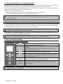
2.6 Connections to the iAquaLink antenna‐box The iAquaLink™ antenna‐box is designed to export data from the AquaLink TRi® to internet (via WiFi or RJ45 Ethernet cable) to be able to remotely control the pool. The internet connection must be stable. The iAquaLink™ antenna‐box is supplied with a wall mounting fixture kit and its quick start guide. The iAquaLink™ antenna‐box must only be installed after having made sure that the selected location allows it to capture the WiFi signal or be connected using an RJ45 Ethernet cable. Refer to the quick start guide supplied with the iAquaLink™ antenna‐box to configure and synchronise with the household internet network. Before fixing the antenna‐box, configure it (see quick start guide), the antenna‐box must be installed 2 metres from the ground and at least 3 metres from any electric motor, appliance or metal object, drill 2 holes in the wall and fix the iAquaLink™ antenna‐box using the supplied hardware kit. place the iAquaLink™ "RS485" power supply cable neatly and connect it to the specific RS485 terminal block on the iAquaLink TRi® electronic board. The cable can be cut if it is too long. Warning: It is prohibited to extend this cable. 1 = green 2 = yellow 3 = black H0369400.B.EN – 2013/03 4 = red 7 2.7 Connecting an iAquaLinkTM compatible appliance Some appliances are compatible with the iAquaLink™ protocol and can therefore have a two‐way exchange with the AquaLink TRi®, allowing to retrieve functionalities and settings on AquaLink TRi® user interface. These compatible appliances will be supplied both by an external power supply and connected to the iAquaLink™ "RS485" connector on the AquaLink TRi® electronic card. iAquaLink™ compatible appliances are: - Zodiac TRi® salt water chlorinator (with or without the TRi pH or TRi PRO module) - Pentair® variable speed pumps of the "VS" type (speed management) If more than 2 iAquaLink™ protocol compatible appliances are to be connected to the "RS485" connector (including the iAquaLink™ antenna‐box), use a multiplexed interface board available as an accessory (not included, see §5.2). the appliance must have a protected, independent and permanent power supply. For the TRi® salt water chlorinator other connections are possible, see §3.5.12. With the appliance powered off, connect it (see the appliance instructions for connection and synchronisation) to the AquaLink TRi® RS485 terminal block using an "RS485" cable (use the remainder of the iAquaLink™ antenna‐box cable if you did not use it all, or buy one as an accessory), Only use "RS485" cable supplied by Zodiac® to connect an iAquaLink™ compatible appliance to the AquaLink TRi® (available as an accessory, see §5.2). the iAquaLink™ compatible appliance must not use its own operating time slots (or Timers) because the AquaLink TRi® will directly manage the programming. The procedure described above is valid for the TRi® salt water chlorinator. Refer to the manufacturer's instructions for all other iAquaLink™ compatible equipment. 3. User interface settings 3.1 Enclosure user interface presentation Green "Power" indicator Red "Alarm" indicator Button to return to the previous screen. To return to the home screen, press this button several times. Navigation in the menu options and value changes when a choice is proposed. Pressing these 2 buttons at the same time for 3 seconds will give access to the "Settings" menu. Button to access a menu, select an action or a value. Pressing for 3 seconds puts the appliance on extended standby (screen off and all pool equipment shut down). A short press turns the appliance back on. Fixed =the appliance is operating Flashing = the appliance is on extended standby Flashes when an alarm message is on the screen or if there is an operating fault. If the language and the units displayed on the screen when the AquaLink TRi® is first powered on are not appropriate, see §3.5.2 and §3.5.3. H0369400.B.EN – 2013/03 8 3.2 Home screens 3.2.1 Main menu Zodiac 14: 26 Zodiac
14: 26 Pool mode Temp1 Temp2 Aux1 Aux2
Settings Devices Service Mode Off Off Off Off Off > > >
More More
The second line on the screen alternatively displays the time, the air temperature, the water temperature (if filtering is operating), solar temperature (if this function has been activated) and possible alarm messages. The main menu displays the status of the main AquaLink TRi® functions. From this screen, all pool equipment connected to the AquaLink TRi® can be activated or started. 3.2.2 Status Zodiac 14: 26 EQUIPMENT STATUS
Filter Pump Temp1 Chlorinator 40% Aux1 Pool Mode Temp1 Temp2 Aux1 Aux2 On 26° Off On Off More
The home screen alternates with the "STATUS" screen if one or more items of pool equipment are operating. This screen gives the detail of currently operating equipment. The "Chlorination XX%" line only appears if a TRi® chlorinator is connected. The eventual information messages issued by the chlorinator will also be displayed here ("No flow", "Check salt", etc.). 3.3 Initial and current settings 3.3.1 Pool mode Activating "Pool Mode" is used to operate the filtering pump by default, and all other related pool equipment such as heating and water treatment. Zodiac
14: 26 Pool Mode Temp1 Temp2 Aux1 Aux2 On Off Off Off Off More
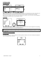
H0369400.B.EN – 2013/03 9 3.3.2 Clock Once installed, the AquaLink TRi® must have its clock set to the current time to be able to operate the pool equipment at programmed times (Timers).
Zodiac Zodiac SETTINGS
SET CLOCK 14: 26 14: 26 14 :26 Pool mode Temp1 Temp2 Aux1 Aux2 Settings Devices Service Mode Off Off Off Off Off Clock Schedules > > > > > . Monday . 14 :26 More Next SET CLOCK Monday . 14 :26 . access the "Programming" menu by pressing the
key, then select the "Clock" menu and validate by pressing press to enter day selection, using the scroll down to the "time" setting using the the
or
keys, validate by pressing by pressing press the , , or
keys, select the day, then validate using key, enter the setting using , , first change the hour using ,then change the minutes using the
or
keys, validate , button as many times as needed to return to the home screen. 3.3.3 Timers "Timers", or operating times, can be defined for each item of equipment connected to the AquaLink TRi®: filtering, heating, cleaner, lighting... There can be up to 10 “Timers” for all equipments combined. Zodiac 14 : 26 Pool Mode Temp1 Temp2 Aux1 Aux2 Off Off Off Off Off
SET CLOCK
14 :26 > > > Clock Schedules SCHEDULES Settings Devices Service Mode > > Filter Pump Temp1 Temp2 Aux1 Aux2 Aux3 > > > > > > More
Zodiac 14 : 26 SCHEDULE Filter Pump More Filter Pump NEW SCHEDULE No Schedules Entered New > H0369400.B.EN – 2013/03
Filter Pump
NEW SCHEDULE . On : 00 :00 . Off : 00 :00 Days : All Days Save
Filter Pump NEW SCHEDULE On : 09 :30 . Off : 00 :00 . Days : All Days Save On : 09 :30 Off : 19 :30 . Days : All Days . Save 10
Filter Pump NEW SCHEDULE Filter Pump . Pgrm : 1 of 4 . On : 09 :30 Off : 19 :30 Days : Weekdays . Save . On : 09 :30 Off : 19 :30 Days : Weekdays New > Change > Delete > access the "Programming" menu by pressing the
key, then select the "Timers" menu and validate by pressing , , select the connected type of appliance (depending on the electric connections) using keys
validate by pressing to create a new "Timer", press to first enter the start hour using the
or
the minutes using the
or
, then change , key, enter the setting using keys, validate by pressing validate by pressing keys, validate by pressing keys, validate by pressing scroll down to the stop time setting using the or
, , press using the
or
, first change the hour ,then change the minutes using the
or
keys, , scroll down to the operating time using the key, enter the setting using , change the operating days using the
or
keys, validate by pressing : - Monday, Tuesday, Wednesday, Thursday, Friday, Saturday or Sunday, - "all" = every day of the week, - "week‐end" = Saturday and Sunday, - "week" = Monday, Tuesday, Wednesday, Thursday, Friday, - "off" = none. save the programme by pressing press the , button as many times as needed to return to the home screen. Repeat the procedure to add other “Timers” for an item of equipment and/or for each item of pool equipment to be programmed: heating, cleaner, lighting, etc. On the next access to the “TIMERS" menu, the saved “Timer(s)” will appear as follows: - “Timer x of x" = to scroll through the different saved “Timers”, - “New” = create a new “Timer”, - “Change” = modify the displayed “Timer”, - “Delete” = delete the displayed “Timer”. A validation screen will then appear to confirm the delete request. 3.4 Equipment settings 3.4.1 Water treatment: Zodiac® TRi® chlorinator Zodiac 14 :26 Settings > Devices > Service Mode > More Boost Low Chlor Output Clock Schedules Actual pH/ACL H0369400.B.EN – 2013/03
SETTINGS 14 :26 CHLOR OUTPUT
SETTINGS 14 :26 Off Off > > > > Pool : 40% Boost Low Chlor Output Clock Schedules Actual pH/ACL Off Off > > > > 11 ACTUAL READING Current pH : 7,3 Setpoint : 7,2 Current ACL : 3 Setpoint : 4 If the pool is fitted with a Zodiac® TRi® salt water chlorinator connected to the AquaLink TRi®, specific menu lines for the chlorinator will appear in the "Programming" menu : Boost = shock‐chlorination activation for a total of 24 hours. Low = limitation to 10% chlorine production if the cover is shut and/or wintering is active. button when the line is highlighted to activate or deactivate the mode. Press the Chlorine Prod. = TRi® chlorine production setting. The TRi® chlorine production setting is only displayed if it is a stand alone TRi® or a pH TRi (the TRi PRO has its own chlorine production regulation). pH/ACL reading = displays the current values and the set points for pH and ACL. The "pH/ACL Reading" menu line only appears if the TRi® chlorinator is operating and if it is fitted with a Tri pH or TRi PRO module. Only pH information will be displayed for a TRi® with the TRi pH module. 3.4.2 Heating system You can activate or deactivate the heating function by managing 2 different set points. These set points are called "Temp.1" and "Temp.2". Zodiac 14 : 26 POOL HEAT Enabled Pool Mode Temp1 Temp2 Aux1 Aux2 Off Off Off Off Off Set To : 26°C Zodiac
14 : 26 Pool Mode Temp1 Temp2 Aux1 Aux2 Off 26° Off Off Off More More
Heating can only start if at least one of the 2 set points is activated and the water temperature is below the active set point. Note: approximately 1 minute will pass before the "Temp.1" or "Temp.2" set point switches from "Auto" to "On". The display will alternate between "26°" and "Auto" if the pool water temperature is greater than or equal to the set point. The display will alternate between "26°" and "On" if the water temperature is below the set point AND "Pool Mode" is "On". If both set points are active at the same time, the highest set point temperature will have priority. If there is a need to immediately cut filtering, press the button for 3 seconds. All the pool equipment connected to the AquaLink TRi® will be shut down, even if a timer is running. Zodiac 14 : 26 POOl HEAT Enabled Pool Mode Temp1 Temp2 Aux1 Aux2 Off 26° Off Off Off Set To : 28°C Zodiac
14 : 26 Pool Mode Temp1 Temp2 Aux1 Aux2 Off 26° 28° Off Off More More
If you stop the "Pool Mode", the filtering will observe a 5 minute delay for the cooling of the heating H0369400.B.EN – 2013/03 12 system if it is operating or shut down for less than 5 minutes. During this delay, "pool mode" will display '***', and the "Temp.1" and/or "Temp.2" lines will alternatively display "Auto" and the set point temperatures. The heating system can remain off for several minutes even if the pool water temperature is 1°C below the active set point (timing). Zodiac 14 :26 Warning : Pump will remain on during cooldown Pool Mode Temp1 Temp2 Aux1 Aux2 On 26° Off Off Off Zodiac
14 :26 Pool Mode Temp1 Temp2 Aux1 Aux2 *** Auto Auto Off Off More More
3.4.3 Auxiliary settings AquaLink TRi® is fitted with 3 power relays used to control 3 different items of electric equipment, whether directly related to the pool or not (see §2.3.4). These 3 items of equipment are named "Auxiliaries" by default, and are displayed as "Aux1", "Aux2", and "Aux3" on the AquaLink TRi® screen. A name can be given to each one of these auxiliaries from the "Settings" menu (see procedure §3.5.7). 3.4.4 Manual equipment control The AquaLink TRi® home screen is simplified to have an overview. The "Equipment" menu is used to see the list of all items of equipment and their operating status. This menu can be used to stop or start each item of equipment independently of any possible programmed "Timers": this is a manual control mode. An "All Off" mode is also available to turn off all equipment at the same time. Zodiac 14 :26 Zodiac 14 :26 Pool Mode Temp1 Temp2 Aux1 Aux2 On 26° Off On Off Settings Devices Service Mode More More > > > DEVICES
14 :26 Filter Pump Temp1 Temp2 Aux1 Aux2 Aux3 All Off
On 26° Off On Off Off 3.4.5 Service mode This is a "safety" mode that blocks its operating to be able to work on an appliance or troubleshoot it without risking a function being activated, either because it is programmed, or because the user has activated it remotely using his/her iAquaLink™ account (Internet or smartphone application). The different available modes are: Auto = normal operating mode, the settings and "Timers" are active. Service = safety mode, all the settings and "Timers" are deactivated. This mode remains active as long as the "Auto" mode is not reactivated. Timed = safety mode equivalent to the "Service" mode but limited to 3 hours. If a user attempts remote operations when the AquaLink TRi® is in "Service Mode" or "Timed", a message will be displayed on his/her iAquaLink™ interface to indicate that all actions are impossible because the "Service Mode" or "Timed" mode is activated. H0369400.B.EN – 2013/03 13 Zodiac 14 :26 Zodiac 14 :26 Pool Mode Temp1 Temp2 Aux1 Aux2 On 26° Off On Off Settings Devices Service Mode > > > SERVICE MODE
Auto . . Service . Timeout More More 3.5 Advanced settings Access the "Settings" menu by pressing and
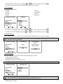
at the same time for 3 seconds. button as many times as needed to return to the home screen. Press the 3.5.1 Anti‐Freeze protection The "Anti Freeze" function automatically starts the filtering pump below a certain air temperature to prevent the pool water from freezing. By default, the "Anti‐Freeze" set point temperature is set to 2°C. The setting range extends from ‐2°C to 5°C. INSTALL SETTINGS FREEZE PROTECT
FREEZE PROTECT
TEMPERATURE Freeze Protect Units Language Clear Memory Pump > > > > > FREEZE PROTECT Set Temp Equipement > > Temp : . 2°C Set Temp Equipement > > More FREEZE PROTECT EQUIPEMENT Filter Pump . Aux1 . Aux2 Aux3 The choice to activate the auxiliaries using the "Anti Freeze "mode is up to the user. Filtering will remain operational as long as the air temperature has not risen above the anti‐freeze set point temperature. An "Anti‐Freeze" warning message will be displayed during this time. 3.5.2 Units The units displayed by the AquaLink TRi® can be selected: degrees: °C or °F time : 24 hours or 12 hour (AM/PM) format.
INSTALL SETTINGS
SET UNITS SET UNITS
Freeze Protect Units Language Clear Memory Pump > > > > > More . °C . 24H Select the "Unit" menu using the
or
select the degrees or time menu using the
H0369400.B.EN – 2013/03 °C . 24H . keys, then validate by pressing or
, keys, then validate by pressing , 14 the unit flashes, select the unit using the
or
keys, then validate by pressing repeat the above procedure to change the time format (12H/24H). , 3.5.3 Languages 8 languages are available: English French Spanish Italian INSTALL SETTINGS German Portuguese Dutch Afrikaans
LANGUAGE Freeze Protect Units Language Clear Memory Pump > > > > > English . Français Español Italiano Deutsch More More Select the "language" menu using the
or
keys, then validate by pressing , Select the chosen language using the
or
keys, then validate by pressing , 3.5.4 INIT Memory "INIT" = Reinitialisation = a function that reinitialises the AquaLink TRi® to its "factory" settings. All user settings will be lost ("Timers", auxiliary names, language, units, etc.). Only the clock (date and time) will not be reinitialised. INSTALL SETTINGS Freeze Protect Units Language Clear Memory Pump CLEAR MEMORY
CLEAR MEMORY
Clear ? > > > > > Clear ? Are you sure you want to clear ? . No . Yes . Cancel . Yes More 3.5.5 Pump type Menu to select the type of pump used by the pool filtering, 3 choices: single speed ("1 speed") two speed pump ("2 speed") variable speed pump (" Variable speed.") By default, AquaLink TRi® is set to operate using a single speed pump. INSTALL SETTINGS Freeze Protect Units Language Clear Memory Pump > > > > > SET PUMP TYPE
1‐Speed . 2‐Speed VSP VSP Setup > More Do not try to change the "PUMP TYPE" with an inappropriate version if a pump is already connected to the filtering relay. This would risk damaging the pump and the relay. H0369400.B.EN – 2013/03 15 Variable speed pump adjustment procedure: SET PUMP TYPE 1‐Speed 2‐Speed VSP VSP Setup > VSP SETUP Model Speeds Assign Speeds Prime Min/Max Freeze > > > > > > Select the variable speed pump model "VS Pump Model" "Speed" = selection and memorisation of the different speeds. Six choices are possible: - Speed 1 assigned to the "Pool Mode" - Speed 2 - Speed 3 assigned to the pressure cleaner (if present) - Speed 4 - Speed for heating (if a specific speed is to be assigned when heating is operating) - Solar speed (if there is solar heating) "Assign speed. " = assign a speed to each auxiliary. The speed for the "Pool Mode" is assigned by default to "None" because it is related to the filtering relay. One of the 3 auxiliaries can be selected for speeds 2, 3, 4 and heating. "Priming" = choice of the speed and duration (from 1 to 5 minutes) of the pump priming mode. "Min/Max" = minimum and maximum speeds authorised by the pump. The default "Min/Max" settings are respectively: 600 rpm and 3450 rpm. "Anti‐freeze" = choice of the pump speed when activated in "Anti‐Freeze" mode. In some cases a specific connection cable will need to be acquired to connect a variable speed pump to the AquaLink TRi® (not supplied by Zodiac®). In all cases, please refer to the installation instructions supplied with the variable speed pump for all of its operating and safety settings. Zodiac® cannot be held liable for failure to comply with the manufacturer's instructions. 3.5.6 Lighting Menu to configure certain multicoloured LED lighting. Once the Led lighting has been assigned to one of the 3 auxiliaries, different colours can be managed when turning on the lighting. INSTALL SETTINGS Color Lights Label Aux Temp Calibrate Assign JVA Ext. SWC Power > > > > > SELECT LIGHT
Jandy Color Jandy Led . Intellibrite Color Logic ASSIGN TO AUX
Jandy LED Aux1 JL. Aux2 Aux3 More Only Led lighting compatible with the list displayed on the AquaLink TRi® is concerned by the "Lighting" menu. All other types of classic incandescent bulb lighting are not concerned (basic electric connection to one of the 3 relays). H0369400.B.EN – 2013/03 16 3.5.7 Name auxiliaries Menu to give a name to each one of the 3 auxiliaries corresponding to the 3 relays available in AquaLink TRi®. INSTALL SETTINGS LABEL AUX Label : Aux1
Color Lights Label Aux Temp Calibrate Assign JVA Ext. SWC Power > > > > > Aux1 Aux2 Aux3 > > > . <Default> . Aerator Blower Backwash Chlorinator More More
3.5.8 Temperature calibration This menu is used to adjust the water temperature displayed by the AquaLink TRi®. This makes it possible to correct an eventual difference between the temperature displayed by the heating system and/or a floating thermometer. Water temperature calibration is used to recover a difference of up to +/‐ 4°C. If the difference to recover is greater, make sure the problem does not come from the temperature sensor you are trying to align with. INSTALL SETTINGS TEMPERATURE
CALIBRATE Color Lights Label Aux Temp Calibrate Assign JVA Ext. SWC Power > > > > > Water : 25°C More 3.5.9 Solar priority (if installed) This menu only appears if a water temperature sensor for solar heating has been installed on terminals 3 and 4 of the green connector on the AquaLink TRi® electronic board (see §2.4.3). If solar heating priority is activated, the solar heating will be used first over the traditional heating. INSTALL SETTINGS SOLAR PRIORITY
Color Lights Label Aux Temp Calibrate Solar Priority Assign JVA > > > > > . Enable . Disable More The use of the "Solar Priority" function implies the mandatory use of a motorised 2 channel valve of the "JVA" (= Jandy Valve Actuator) type of which availability depends on the country you are in. This function will not therefore be available in all countries. 3.5.10 Assign JVA This menu is exclusively for the use of motorised 2 channel "JVA" (= Jandy Valve Actuator, see wiring diagram §2.3.1) valves. Availability is therefore variable depending on each country. The use of JVA motorised valves is designed to manage a "Pool + Spa" combination, or when the filtering is switched to the Spa circuit when the Spa is in use. AquaLink TRi® can manage 3 "JVA"s: a motorised valve for suction = "Intake" on the electronic board and "Input" on the AquaLink TRi® menu. a motorised valve for discharge = "Return" on the electronic board and "Output" on the AquaLink TRi® menu. a motorised valve for solar heating = "Solar" on the electronic board and "Solar" on the AquaLink TRi® menu. H0369400.B.EN – 2013/03 17 INSTALL SETTINGS ASSIGN JVA Color Lights Label Aux Temp Calibrate Solar Priority Assign JVA > > > > > ASSIGN JVA
Intake Intake Free Return Free Solar Used None . Aux1 Aux2 Aux3 More 3.5.11 Assign "HotKeys" (if present) This menu only appears if the optional AquaPalm remote control is used and turned on (see AquaPalm instructions). The AquaPalm remote has 2 hotkeys numbered "1" and "2". This menu is used to configure the function assigned to each one of these buttons. The "1" and "2" hotkeys on the AquaPalm remote are called "Hotkeys" in the AquaLink TRi® menu. INSTALL SETTINGS ASSIGN HOTKEYS
Assign Hotkeys Ext. SWC Power Diagnostics > > > HOTKEY #1 1 Aux1 . 2 Aux2 More Aux1 . Aux2 Aux3 Filter Pump Pool Heat Solar Heat 3.5.12 Zodiac® SWC Supply This menu is used to define the electric power supply source for the Zodiac® TRi salt water chlorinator if the pool is fitted with one. It is essential that this information be correctly entered if a TRi® chlorinator is present because it is used to link its operation to the filtering pump operation (= "Pool Mode"). INSTALL SETTINGS EXT. SWC POWER
Assign HotKeys Ext. SWC Power Diagnostics > > > More None . Aux1 Aux2 Aux3 Filter Pump "None" = the TRi® is connected to a permanent power supply that is external to the AquaLink TRi® (or connected to the "input" side of one of the relays, see § 2.3.3 and § 2.3.4). "Aux1" / "Aux2" / "Aux3" = the TRi® is connected and assigned to one of the 3 auxiliary relays. "Filtering" = the TRi® is connected to the same power relay as the filtering pump ("output" side of the first relay, see §2.3.3). It’s recommended to use an external and permanent mains supply for Zodiac® salt water chlorinator. The parameter should consequently be set to “None”. 3.5.13 Troubleshooting The "Troubleshooting" menu is for AquaLink TRi® maintenance. It is used to access the different internal programme versions (called "Firmware"), to the eventual ongoing alarms, and to the diagnosis of the communications quality between the different iAquaLink™ compatible appliances (RS485 type). H0369400.B.EN – 2013/03 18 INSTALL SETTINGS DIAGNOSTICS
REVISIONS
Assign Hotkeys Ext. SWC Power Diagnostics > > > Revisions > Alerts > RS‐485 Devices > UI : 1.60 Bootloader : 0.26 FFC : 0.18 iAquaLink : 2.2.0 SWC : 3.00 Suivant UI = Aqualink TRi® user interface firmware Bootloader = AquaLink TRi® internal OS firmware FFC = AquaLink TRi® electronic board firmware iAquaLink = iAquaLink™ antenna‐box firmware SWC = TRi® salt water chlorinator firmware (if present) DIAGNOSTICS CURRENT ALERTS
Revisions > Alerts > RS‐485 Devices > DIAGNOSTICS
Revsions > Alerts > RS‐485 Devices > RS‐485 DEVICES AQP : 95% E : 3 FFC : 99% E : 1 VSP : 88% E : 12 iAL : 94% E : 5 SWC : 82% E : 25 . Clear Stats . : only the ongoing alarm messages appear. : RS‐485 diagnosis: AQP = AquaPalm communications quality (if present) FFC = AquaLink TRi® internal communications quality VSP = Variable speed pump communications quality (if present) iAL = iAquaLink™ antenna‐box communication quality SWC = TRi® salt water chlorinator communication quality (if present) The percentages shown on the "DIAG‐RS‐485" screen are only indications and are not designed to troubleshoot the communications quality between the equipment. A low value usually means low quality or inappropriate cabling, or electromagnetic interference related to the bad position of the appliance and/or its RS485 cable. The "E"s displayed on the right of the "DIAG RS‐485" screen express the number of information exchange faults. They do not indicate an error or a fault but are related to the communications quality percentage. The "E" counter can be reinitialised to zero by selecting "INIT Values". 3.6 Wireless User Interfaces In addition to the existing user interface on AquaLink TRi® enclosure, it’s possible to remotely manage the pool via several wireless user interfaces: - Dedicated Web access on www.iaqualink.com - Free apps for compatible smartphones - Optional AquaPalm remote control 3.6.1. www.iaqualink.com website Once the AquaLink TRi® is installed and configured, you will need to register on www.iaqualink.com website to create your iAqualink user account. It will be necessary to provide the iAquaLink™ antenna serial number (written on the side of iAquaLink™ antenna and printed on door hanger). For further details, please refer to iAquaLink™ quick start guide provided in the iAquaLink antenna carton box.
Depending on your internet connection type, user interface commands responsiveness may be more or less prompt. Do not attempt to select the same function repeatedly to prevent any unwanted « on/off » situations on AquaLink TRi® unit H0369400.B.EN – 2013/03 19 3.6.2 Smartphone apps 3 different types of free smartphone apps are available for the following platforms : - Android® smartphones : - Apple® iOS smartphones : - Touchscreen smartphones compatibles with HTML5 protocol www.iaqualink.com/mobile (« app in a browser ») : available on iAquaLink™ user account must have been created on www.iaqualink.com website prior to be able to use smartphone apps. 3.6.3 Optional AquaPalm remote control An optional AquaPalm remote control is available to be able to manage your AquaLink TRi® from your homestead. Ask your reseller for any information. 4. Operational safety 4.1 Heating cooldown timer If "Pool Mode" and the heating are operating at the same time, and if "Pool Mode" is turned to "Off", the filtering pump will continue to operate alone for 5 minutes. A warning message "Heater Cooldown" will displayed during this time. A flashing "***" symbol will be displayed on the "Pool Mode" menu. An emergency stop is always possible by pressing the button for 3 seconds. 4.2 Heating start‐up timer Heating can only start if at least one of the 2 set points is activated ("Temp.1" and/or "Temp.2") and the water temperature is below the active set point. However, the heating system will not start immediately after a set point has been activated: a delay of one minute will be observed before the "Temp.1" or "Temp.2" set point switches from "Auto" to "On". An additional start‐up timer applies when a heat pump is connected to the AquaLink TRi®. This timer varies from 3 to 5 minutes depending on the models between the time the AquaLink TRi® sends the start‐up command and the actual start‐up of the heat pump. 4.3 Heating regulation timer To avoid repeated start/stops when the pool water temperature is very close to the set point, a 3 minute timer is applied between each heating start‐up command. It is therefore normal that the heating system can remain off for several minutes even if the pool water temperature is 1°C below the active set point. 4.4 Filtering timer with JVA valves "Pool Mode" stops when a JVA motorised valve is activated (as well as the "Pool cleaner" if applicable). The procedure lasts about 35 seconds. The "Pool Mode" restarts as soon as this operation is complete. 4.5 Cleaner lock The pressure pool cleaner (controlled by its booster pump, itself connected to the AquaLink TRi®) can only operate if the "Pool Mode" is activated and operational for more than 3 minutes. If the "Cleaner" is active when the "Pool Mode" is "Off", "Pool Mode" will start automatically and the "Cleaner" will start after a 3 minute timer (a message will be displayed on the Aqualink TRi® screen and the flashing "***" symbol will be displayed on the "Cleaner" menu line). H0369400.B.EN – 2013/03 20 4.6 Anti‐Freeze safety The "Anti‐Freeze" safety is a native AquaLink TRi® function, it cannot be deactivated. When the air temperature is lower than the Anti‐Freeze set point (adjustable in the "Settings" menu, see §3.5.1.), the filtering pump will start‐
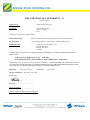
up automatically. It will remain operational as long as the air temperature has not risen above the anti‐freeze set point temperature. An "Anti‐Freeze" warning message will be displayed on the screen during this time. 5. Maintenance 5.1 Maintenance instructions It is recommended to carry out general servicing of the appliance once per year, in order to check its correct operation and maintain its performances, as well as to prevent certain possible defects. These actions are the user's responsibility and must be carried out by a qualified technician. Clean the outside of the appliance, do not use solvent based products, check the electric elements, check the connection of metal casing to the Ground, check the tightness of the electric wire connections and the cleanliness of the control box. 5.2 Available accessories Name Multiplex interface board Air/Water/Solar temperature sensor RS485 cable AquaPalm Representation 5.3 Recycling This symbol means that your appliance must not be put in the dustbin. It will be subject to selective waste sorting with a view to its reuse, recycling or sale. If it contains substances that are potentially harmful to the environment, they will be eliminated or neutralised. Ask your reseller for information about recycling. 6. Registering the product Register your product on our website: - You will be the first to be informed of new Zodiac products and special offers, - You can help us to constantly improve our product quality. Australia – New Zealand South Africa Europe and rest of the world www.zodiac.com.au www.zodiac.co.za www.zodiac‐poolcare.com H0369400.B.EN – 2013/03 21 DECLARATION OF CONFORMITY - 13
January 15, 2013
Organization:
Zodiac Pool Systems, Inc.
Located at:
2620 Commerce Way
Vista, CA 92081
USA
Declare that the products identified below:
Product Description:
Electric Swimming pool and spa equipment control/switching center
Model Number:
« Zodiac AquaLink Z4 » ; also sold as « Zodiac AquaLink Tri »
Manufactured at :
Zodiac Group Australia Pty., Ltd
23 Southfork Drive
Kilsyth, VIC 3137
Australia
COMPLY WITH THE RELEVANT ESSENTIAL REQUIREMENTS OF THE FOLLOWING EUROPEAN
DIRECTIVES:
LOW VOLTAGE DIRECTIVE (LVD) -- 2006/95/EC
ELECTROMAGNETIC COMPATIBILITY (EMC) DIRECTIVE – 2004/108/EC;
THE PRODUCTS – and all the critical components used therein -- ARE DESIGNED AND MANUFACTURED IN
ACCORDANCE WITH THE RELEVANT REQUIREMENTS OF THE ABOVE REFERENCED DIRECTIVES
AND ALSO IN ACCORDANCE WITH THE RELEVANT REQUIREMENTS OF:
Standards:
IEC 60335-1:2010;
IEC 61000-1;
CB Test Certificates : SE-71663 ; SE-71651
Declared by:
_______________________________
Signature
Shajee R. Siddiqui________________
Name
Director, Global Product Safety & Compliance
Title/Position
IEC 61000-3
Zodiac pool Care Europe - BP 90023 - 49180 St Barthélémy d ’Anjou cedex - France / S.A.S.U. au capital de 517 200 € / SIREN 395 068 679 / RCS PARIS
www.zodiac-poolcare.com
Pour plus de renseignements, merci de contacter votre revendeur.
For further information, please contact your retailer.
ZODIAC® is a registered trademark of Zodiac International, S.A.S.U., used under license.
Votre revendeur / your retailer