1
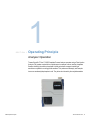
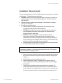
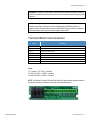
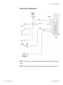
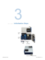
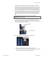
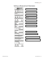
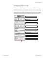
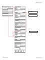
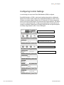
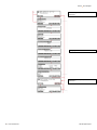
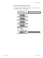
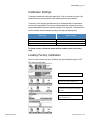
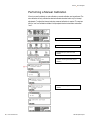
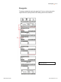
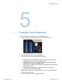
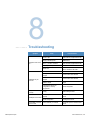
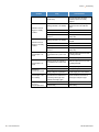
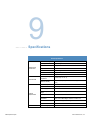
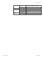
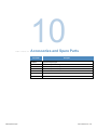
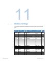
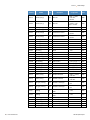
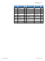
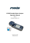
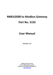
User Manual
Thermo Scientific Orion
2395 Phosphate Analyzer
270118-001 • Revision B • August 2015
Contents
Section 1 ....................................................................................................................... 5
Operating Principle ...................................................................................................... 5
Analyzer Operation ...................................................................................................................... 5
Section 2 ....................................................................................................................... 7
Analyzer Installation..................................................................................................... 7
Mechanical Description................................................................................................................ 7
Installation Requirements ............................................................................................................ 8
Terminal Block Interconnection.................................................................................................... 9
Electrical Installation .................................................................................................................. 10
Section 3 ..................................................................................................................... 11
Initialization Steps ...................................................................................................... 11
Section 4 ..................................................................................................................... 15
Menu Navigation ......................................................................................................... 15
Turning the Analyzer On ............................................................................................................ 15
Start Analyzer ............................................................................................................................ 16
Configuring the Analyzer ........................................................................................................... 16
Setting up Measurement Parameters ........................................................................................ 17
Configuring Transmission .......................................................................................................... 18
Configuring Control Settings ...................................................................................................... 20
Return to the Reading Screen ................................................................................................... 24
Calibration Settings.................................................................................................................... 25
Loading Factory Calibration ....................................................................................................... 25
Performing a Manual Calibration ............................................................................................... 26
Reagents ................................................................................................................................... 27
Section 5 ..................................................................................................................... 29
Analysis Cycle Sequence .......................................................................................... 29
Section 6 ..................................................................................................................... 31
Error Messages........................................................................................................... 31
Section 7 ..................................................................................................................... 33
Preventative Maintenance.......................................................................................... 33
Semi-Annual Maintenance......................................................................................................... 33
Annual Maintenance .................................................................................................................. 33
Bi-Annual Maintenance.............................................................................................................. 33
Maintenance schedule ............................................................................................................... 34
Section 8 ..................................................................................................................... 35
Troubleshooting ......................................................................................................... 35
Section 9 ..................................................................................................................... 37
Specifications ............................................................................................................. 37
Section 10.................................................................................................................... 39
Accessories and Spare Parts .................................................................................... 39
Section 11.................................................................................................................... 41
Modbus Settings......................................................................................................... 41
Section 12.................................................................................................................... 45
Procedure to Disconnect the Analyzer ..................................................................... 45
Section 13.................................................................................................................... 47
Customer Service ....................................................................................................... 47
Notice of Compliance ................................................................................................................. 47
Declaration of Conformity ........................................................................................................... 48
Terms and Conditions ................................................................................................................ 49
Contact Information........................................................................................................... 49
Minimum Order................................................................................................................. 49
Rush Orders ..................................................................................................................... 49
Returning Goods............................................................................................................... 49
Hazardous Materials ......................................................................................................... 50
Restocking Charge ........................................................................................................... 50
Short Shipments ............................................................................................................... 50
Force Majeure .................................................................................................................. 50
Warranty ........................................................................................................................... 50
1
SECTION 1
Operating Principle
Analyzer Operation
Thermo Scientific™ Orion™ 2395 Phosphate Process Analyzer operates using a Flow Injection
Analysis (FIA) system coupled with an optical sensor to measure ortho or reactive phosphate.
Sample containing the reactive phosphate is initially mixed with a reagent consisting of
ammonium molybdate in a strongly acidic medium. This produces a heteropoly acid complex
known as vanadomolybdophosphoric acid. The yellow color formed by the molybdovanadate
2395 Phosphate Analyzer
Thermo Scientific Orion | 5
Section 1 | Operating Principle
phosphoric acid is proportional to the concentration of reactive phosphate.
In general, FIA involves the rapid injection of the sample under continuous flow. Sample is
mixed with the reagent before entering the detection system.
During this process, the sample disperses and mixes with the reagent to form a homogenous
solution, which is delivered to the measurement cell. Inside the measurement cell, the samplereagent mixture is held until the reaction is complete and the absorbance signal is acquired.
The reacted solution is displaced by the next sample entering the measurement cell. As the
new sample-reagent mixture enters it rinses the cell to ensure there is no cross-contamination.
FIA is suitable for highly reproducible analyses with low reagent consumption, promoting a high
sample throughput and minimizing contamination.
6 | Thermo Scientific Orion
2395 Phosphate Analyzer
2
SECTION 2
Analyzer Installation
Mechanical Description
The analyzer consists of a durable light weight plastic cabinet, containing separate electronics
and fluidics compartments. The enclosure is IP-56 rated with dimensions of 13.1 in x 16.3 in x
5.7 in (333 mm x 413 mm x 145 mm) and can be wall or panel mounted on a flat surface. The
analyzer cabinet has three standardized 1/2" cable glands and terminal strips for connecting to
a power source and communication cables.
1. Electronic Module
2. Overflow
3. Dosing Pump
4. Measurement cell
5. FIA System
6. Standard
7. Reagent
2395 Phosphate Analyzer
Thermo Scientific Orion | 7
Section 2 | Analyzer Installation
Installation Requirements
To ensure optimal performance of the Orion 2395 phosphate continuous analyzer, it is critical to
install it correctly. The following steps must be followed:
1. CAUTION: In addition to the specific requirements listed in this manual, main power and
product installation must be in accordance governing national, local electric codes and
safety regulations.
2. After the removing the analyzer from the packaging, confirm that there is no damage
resulting from transportation.
3. Follow the recommendations below:
a. Install the analyzer in an easily-accessible location, free of vibrations, smoke,
corrosive fumes, water spray and chemical substances.
b. CAUTION: Direct sunlight may cause the internal temperature of the equipment to
rise, risking damage to the analyzer and its reagents. We recommend using a
protective covering with the analyzer.
c. CAUTION: Confirm the cable glands are dry and holding their respective
interconnection cables tightly. Moisture will decrease the impedance, causing
measurement errors. If there is a small gap, strap the cable with high-heat tape until
you get a perfect grip on the cable gland. Never use silicone. This procedure will help
preserve the protective characteristics of the housing (IP-56).
d. Periodically replace the O-ring seals to ensure a good seal in the housing. Make sure
the lids are securely fastened, to ensure a good seal.
WARNING: Never install the analyzer near pumps or motors with industrial loads (source of
electromagnetic discharge), or on the same network that feeds the motor. This may cause
equipment malfunction or damage to the unit.
4. Proceed to connect the wiring from the power cord to the terminals using the Terminal
Block Interconnection table on Page 9 and the Electrical Installation Wiring Diagram
on Page 10.
5. Inspect all wiring to ensure the connections are correct.
6. Check that power supply is stable. The analyzer will only operate correctly on a
voltage rating between 90 to 240 VAC (50/60Hz). Confirm that the correct voltage is
being supplied.
7. The lack of proper grounding can cause serious damage to the equipment. The
voltage between ground and neutral cannot exceed 5V. If it is above this threshold,
there is bad ground or an unbalanced load. In this case, turn the circuit breakers on at
the electric power switch panel after checking voltage between ground and neutral.
8 | Thermo Scientific Orion
2395 Phosphate Analyzer
Analyzer Installation| Section 2
WARNING: The supply of control valves, solenoids, alarms and other components should be
directly connected to the electrical panel and never on the same circuit as the analyzer (phase
recovery).
WARNING: The power supply cables must be physically isolated with cable glands, separate
from the other cables. Wiring for the 4-20mA and digital signals (RS-485) must be in a
separate conduit. Solenoid cables must also be separated in their own conduit. If needed the
solenoid and power cable may be placed through the same conduit.
Terminal Block Interconnection
Posts
Connections
1
Grounding
2 and 3
Power supply 90 to 240 VAC (50/60Hz)
4 and 5
S1-Alarm or Control set point
6 and 7
S2-Alarm or Control set point
8 and 9
External control-Remote control for Stand-by
10,11 and 12
Digital communication output RS-485
13 and 14
Current output 4-20mA - Channel 1
15 and 16
Current output 4-20mA - Channel 2
Fuses
F1 = General (1.6 A / 250 V) - slow blow
F2= Set. Point (SP1) - 1A/250 V - fast blow
F3= Set. Point (SP2) - 1A/250 V - fast blow
NOTE: The External Command (Terminal Posts 8 and 9) is used when the equipment needs to
be placed in Stand-by (for example, in the case of a process interruption).
2395 Phosphate Analyzer
Thermo Scientific Orion | 9
Section 2 | Analyzer Installation
Electrical Installation
NOTE 1: It is important to use separate cables and phases for equipment and control valves or
alarms.
NOTE 2: Cable shield 3 (terminal 12) should be installed on the terminal block connector only.
10 | Thermo Scientific Orion
2395 Phosphate Analyzer
3
SECTION 3
Initialization Steps
Standard
bottle
Reagent
bottle
Tubing
Cap assembly
Analysis drain
2395 Phosphate Analyzer
Overflow drain
Thermo Scientific Orion | 11
Section 3 | Initialization Steps
1. Install tubing at the overflow drain and a collector or funnel at the drain just below the
analysis module. Leave the analysis drain and the overflow drain "open" to prevent back
flow. The solution exiting through the overflow drain is pure process sample which can be
returned to the process stream, if desired. Analysis flow rate is 40 mL per reading. The
analysis drain must be discarded as it contains both process sample and reagents/residue.
2. Taking the reagent and standard bottles, remove each of the caps. Identify the tubing and
cap assembly corresponding to the reagent and standard. Insert the tubing with check
valve (white pieces at the ends of the hoses) into each respective bottle and tighten the
caps.
3. Place the reagent and standard bottles in the analyzer reagent compartment.
WARNING: DO NOT invert the bottles.
4. Connect the process sample line to the sample inlet ½” NPT fitting on the base of the
Overflow cell. Confirm there are no leaks. Measure flow with a beaker at the over flow drain
outlet. The sample flow should be 70 mL/minute.
Overflow
cell
Process sample inlet ½” NPT
5. Tighten the four screws on the dosing pump (they are shipped loose).
6. Make sure that the turbidity of the process does not exceed 20 NTU.
7. Connect the analyzer to electrical power. After startup the analyzer will show the date
and time screen which will then proceed to the reading screen.
12 | Thermo Scientific Orion
2395 Phosphate Analyzer
Initialization Steps | Section 3
8. Access SETUP mode and configure the INDICATION menu options at analyzer menu
(see page 16 – Configuring the analyzer).
9. Access SETUP mode and configure measure at analyzer menu (see page 16 –
Configure the analyzer).
10. Access the SETUP mode and adjust transmission values (see page 18 - Configure
Transmission).
11. Access reagents mode and refill hoses (see page 27–Reagents).
12. Let the analyzer acquire measurements for at least 2 hours.
13. Tighten the four screws on the dosing pump again.
14. Access to CALIBRATE mode and perform a manual calibration (see page 26 –
Performing manual calibration).
15. The analyzer is ready for on-line analysis of sample.
2395 Phosphate Analyzer
Thermo Scientific Orion | 13
Section 3 | Initialization Steps
14 | Thermo Scientific Orion
2395 Phosphate Analyzer
4
SECTION 4
Menu Navigation
Turning the Analyzer On
Menus are designed for easy navigation and operation.
To enter or change data, the menu always provides flashing display options.
In order to access these options, press the SELECT and ENTER keys.
The BACK key is used to change options or correct unwanted data (it always returns to the
previous menu options).
When powering up the analyzer, the model and revision of software are indicated on the
display.
2395 Phosphate Analyzer
Thermo Scientific Orion | 15
Section 4 | Menu Navigation
Start Analyzer
Reading Screen
Press the menu key to access configuration
screen or standby key to put analyzer in stand-by
mode
Note: During the menu navigation the analyzer continues to perform the measurement routine. Only if the analyzer is
placed in STAND BY will the measurement routine stop.
Type passcode 220. Press and hold enter for 5 seconds to accept the password.
Configuring the Analyzer
The configuration step allows preferences for the measurement to be selected. This includes
preferred units, preferred parameter output, resolution, calibration point value as well as time
between calibrations and analysis.
Setting up language, date and time:
Reading Screen
Configuration screen
Enter passcode 220 to access setup screen
Setup screen
Press indicat. key
Select language
Adjust date and time
16 | Thermo Scientific Orion
2395 Phosphate Analyzer
Menu Navigation | Section 4
Setting up Measurement Parameters
Reading Screen
Configuration screen
Enter passcode 220 to access setup screen
Setup screen
Press measure key
Select measure unit
Select measure parameter
Select measure resolution
Configure the standard - value between 5 to 50 ppm
Configure calibration frequency - time between 24 to 72 hours
Configure period between each measure - time between 0 to 45
minutes
2395 Phosphate Analyzer
Thermo Scientific Orion | 17
Section 4 | Menu Navigation
Configuring Transmission
The transmission configuration section allows the analog outputs, and RS485 to be configured.
BURN-OUT function allows an analog output either 4mA or 20mA signal to be selected. During
a failure mode the selected signal is transmitted to alert the control room of the analyzer status.
Swap float Point is used in MODBUS communication protocol to allow information in registers
to be swapped for communication between the RS485 of the analyzer and the inlet of a PLC.
Reading Screen
Configuration screen
Enter passcode 220 to access setup screen
Setup screen
Configure first analog output
Configure 4mA value point
Configure 20mA value point
Configure 4-20mA output
18 | Thermo Scientific Orion
2395 Phosphate Analyzer
Menu Navigation | Section 4
This screen appears only if output
is set for control
Configure second analog output
Configure digital output
2395 Phosphate Analyzer
Thermo Scientific Orion | 19
Section 4 | Menu Navigation
Configuring Control Settings
In control settings, the set point and Pulse Width Modulation (PWM) is configured.
Pulse Width Modulation, or PWM, is a technique for getting analog results in a digital mode.
Digital control is used to create a square wave, a signal switched between on and off. This onoff pattern can simulate voltages in between full on (5 Volts) and off (0 Volts) by changing the
portion of the time the signal spends on versus the time that the signal spends off. The duration
of "on time" is called the pulse width. To obtain varying analog values, the pulse width can be
changed, or modulated. Repeating this on-off pattern rapidly will result in a signal that appears
as a steady voltage between 0 and 5v. This is a PWM signal.
Reading Screen
Configuration screen
Enter passcode 220 to access setup screen
Setup screen
Configure first control
20 | Thermo Scientific Orion
2395 Phosphate Analyzer
Menu Navigation | Section 4
Configure second control
2395 Phosphate Analyzer
Thermo Scientific Orion | 21
Section 4 | Menu Navigation
This screen appears only if output is set for
transmission
Configuring PID first control
This screen appears only if output is set for
transmission
22 | Thermo Scientific Orion
2395 Phosphate Analyzer
Menu Navigation | Section 4
Configuring PID second control
2395 Phosphate Analyzer
Thermo Scientific Orion | 23
Section 4 | Menu Navigation
Return to the Reading Screen
On completing the configuration procedure in the setup screen, the screen sequences below
show the steps required to return to the Reading screen.
Setup screen
Reading screen
24 | Thermo Scientific Orion
2395 Phosphate Analyzer
Menu Navigation | Section 4
Calibration Settings
The analyzer automatically monitors the reagent level. To set up, just enter the volume of the
reagent bottle when replacing the bottle. After resetting, perform an auto calibration.
The accuracy of the equipment was determined by the standard deviation of measurements
over the entire range specified. The accuracy of measurements was compared to previously
prepared standards and used in the automatic calibration of the equipment. The standard to be
used for calibration should be selected according to the range (see following table).
Working range
Calibration standard
0 to 10 ppm
5.0 ppm
10 to 30 ppm
20.0 ppm
30 to 50 ppm
40.0 ppm
For greater accuracy, calibrate the analyzer with the standard closest to the working
range.
Loading Factory Calibration
If there is a need to reset to the Factory Calibration, this may be selected through the “FACT
CAL” option as shown below:
Reading Screen
Press CAL key to select the calibration menu
Calibration mode
Press FACT CAL key to load the factory calibration
parameters
Confirm your choice
YES to load the FACT CAL
2395 Phosphate Analyzer
Thermo Scientific Orion | 25
Section 4 | Menu Navigation
Performing a Manual Calibration
If there is a need to calibrate, an auto-calibration or manual-calibration can be performed. The
auto-calibration will only calibrate the selected calibration standard and is only for intercept
adjustments. To adjust the intercept and slope a manual calibration is required. This requires
both the “zero” and calibration standard. Use phosphate-free de-ionized water as standard
"zero".
Reading screen
Press CAL key
Press MAN CAL key to perform the manual
calibration
Initialize manual calibration (MAN CAL)
Calibration of the zero ppm standard (first point
calibration)
Calibration of 5 (20 or 40) ppm-second point
calibration
26 | Thermo Scientific Orion
2395 Phosphate Analyzer
Menu Navigation | Section 4
Reagents
The analyzer automatically monitors the reagent level. To set up, enter the volume of the
reagent bottle when replacing the bottle. After resetting, perform an auto calibration.
Configure reagent volume
2395 Phosphate Analyzer
Thermo Scientific Orion | 27
2395 Phosphate Analyzer
Thermo Scientific Orion | 28
Menu Navigation | Section 5
5
SECTION 5
Analysis Cycle Sequence
To verify an analysis cycle sequence, perform the following procedure:
1. Loosen the screw on the measurement cell cover. Lift and open the cover.
2. Access the READING screen on the analyzer display.
3. Check that the analysis cycle consists of the following steps:
a. Sample injection for the initial cleaning of reaction cell and subsequent drainage
(indicated by the prompt “clean” in the reading screen)
b. Sample injection for the second cleaning of reaction cell and subsequent drainage
(indicated by prompt “clean” in the reading screen)
c. Sample injection for determination of turbidity and subsequent drainage (indicated by
the prompt “turb. Comp”.)
d. Sample injection with a reagent for the determination of the ortho phosphate
concentration (indicate by prompt “reading”)
Note: If any of the steps a, b, c or d are missing, call your local Thermo Fisher Scientific
office for technical assistance.
4. Close the measurement cell cover and tighten the screw.
2395 Phosphate Analyzer
Thermo Scientific Orion | 29
2395 Phosphate Analyzer
Thermo Scientific Orion | 30
Menu Navigation | Section 6
6
SECTION 6
Error Messages
When there is an analyzer error, the display will continually switch between a screen that shows
the reading and another with an error message. The following are the possible messages:
In Reading:
Message on the display: Check Reagent
When the REAGENT level is independently equal to or less than 5 days
Message on the display: Check Standard
When the STANDARD level is independently equal to or less than 5 days.
Message on the display: Check Calib. Factory outside limits
When CALIBRATION FACTOR (point of auto-cal/value read) ≤ 0.7 or ≥ 1.3 (equal to an error ± 30% of
reading).
Message on the display: Check Drain
When a problem in the drain occurs, the analyzer will sense a problem due to the lack of change in the state
for a long time while the reading is on.
2395 Phosphate Analyzer
Thermo Scientific Orion | 31
Section 6 | Error Messages
In Calibration:
In REAGENTS option> STANDARD> START STANDARD
After injecting the standard from the new bottle, the analyzer will provide a prompt to repeat the MAN-CAL.
The system will perform for the MAN-CAL process. If the calibration factor is outside the range of 0.7 to 1.3,
the analyzer will display the following on the screen for 5 seconds: STANDARD AUTO OUTSIDE
ACCEPTABLE LIMITS. Check STANDARD!
However, If the calibration factor differs up to ±15% of standard calibration factor, the analyzer will accept the
new calibration factor. Otherwise, if the calibration factor differs more than ±15%, the instrument will display
the following message on the screen for 5 seconds: STANDARD AUTO OUTSIDE ACCEPTABLE LIMITS.
Check STANDARD!
In this case the analyzer will maintain the previous calibration and display the message “Check Calibration”.
32 | Thermo Scientific Orion
2395 Phosphate Analyzer
7
SECTION 7
Preventative Maintenance
For proper operation of the equipment, the following preventative maintenance should be
performed while wearing protective equipment:
Semi-Annual Maintenance
1. Replace the o-ring seals and replace the hoses on the measurement system designed to
prevent leakage risks to the system.
2. Clean overflow cell with a solution of hydrochloric acid (3.7%). Wear protective equipment
during this procedure.
3. Clean particulate filter.
Refer to 2395MK6 maintenance sheet part number 271031 for details on performing 6 month
maintenance.
Annual Maintenance
Replace pinch rollers in dosing pump module.
Refer to 2395MK12 maintenance sheet part number 271032 for details on performing 12 month
maintenance.
Bi-Annual Maintenance
1. Change overflow cell.
2. Change particulate filter.
2395 Phosphate Analyzer
Thermo Scientific Orion | 33
Section 7 | Preventative Maintenance
Refer to 2395MK24 maintenance sheet part number 271033 for details on performing 24 month
maintenance.
Maintenance schedule
The following maintenance schedule should be maintained based on a 6, 12, 18 and 24 month
cycle. If the maintenance has exceeded 24 months then the cycle is repeated starting at 6
months.
Maintenance months
Maintenance consumables
required
6
2395MK6
12
2395MK6+2395MK12
18
2395MK6
24
2395MK6+2395MK12+2395MK24
8
SECTION 8
Troubleshooting
Symptom
Equipment does not turn
on
Calibration may be
incorrect
Equipment is not reading
correctly
Serial port does not work
Control/Relay 4 to 20mA
does not work
2395 Phosphate Analyzer
Verify
Corrective Action
Fuse F1 open
Replace the fuse (equipment turned off)
Supply of electrical power
Check circuit breaker at the electrical
distribution box
Pins 1, 2, 3 of CN-1 connector
Check connector (equipment turned off)
Power input of the system
Measure outlet/breaker
Power cord
Check that the cable is not broken, or
that it is connected to the outlet
Volume of the standard
Use new volume of the standard
Validity of the standard solution or
reagent
Use new volume of the standard
Deteriorated standard solution or
reagent
Use new volume of the standard
White on sample
Perform calibration of white on the
sample
If the reference value in the
configuration is correctly
programmed
Perform configuration
Tubing
Replace tubing and seals
If the serial port is connected
properly
Connect the system as instructed in the
manual
System configuration
Access menu and configure the RS-485
according to the manual
If the control/relay is connected
Connect the system as instructed in the
manual
Thermo Scientific Orion | 35
Section 8 | Troubleshooting
Symptom
Set-Point 1 does not
trigger or is in faulty
condition
Set-Point 2 does not
trigger or is in a faulty
condition
Current output 1 of 4 20mA
Current output 2 of 4 20mA
Equipment is
automatically restarted
Current output 1 and 2
are oscillating
Equipment is not reading
the correct
orthophosphate value
36 | Thermo Scientific Orion
Verify
Corrective Action
System setup
Access the setup menu and select
control/relay option if it is correctly
configured
Setting (if Set-Point 1 was enabled)
Enable the Set-Point 1 by selecting
settings in the menu and enable SetPoint 1
Pins 6 and 7 of CN-1 connector
Check if cable wires are connected
F2 fuse open
Replace the fuse
Check if power is VAC and
Imax=1A
See wiring manual. If I> 1A, replace
auxiliary relay
Setting (if Set-Point 2 was enabled)
Enable the Set-Point 2 by selecting
SETTING
Pins 6 and 7 of CN-1 connector
Check if cable wires are connected
F3 fuse open
Replace the fuse
Check if power is VAC and
Imax=1A
See wiring material (if I>1A, replace
auxiliary relay)
Setting (if values were adjusted for
4 and 20mA for CN-1 posts 12 and
13)
Enable and adjust values for 4 to 20mA
by selecting SETTING
If the load is less than 850Ω
Correct by adjusting the load to 850Ω
Setting (if values were adjusted for
4 and 20mA for CN-1 posts 10 and
11)
Enable and adjust values for 4 to 20mA
by selecting SETTING
If the load is less than 850Ω
Correct by adjusting the load to 850Ω
Grounding
Check grounding connection
Supply voltage out of specification
Regulate supply power for 90-240VAC.
If Δ between 4 to 20mA output is
proportional to the oscillation due to
a small range for the ppm scale
selection for example 0-1ppm
Increase Δ between 4 and 20mA to a
wider range for example 0-10ppm
Check default value set
Verify the correct value
Injection tubing
Replace tubing
2395 Phosphate Analyzer
9
SECTION 9
Specifications
Product Specifications
Measurement
Performance
Environmental
Sample
Requirements
Construction
2395 Phosphate Analyzer
Measurement Range
0.2 to 50.0 ppm PO43-
Accuracy
5% or 0.1 ppm
Resolution
0.1 ppm
Response Time
15 minutes
Precision
3% or 0.1 ppm
Limit of Detection
0.2 ppm
Method
Optical absorption at 460 mm
Ambient Operating
Temperature
5 to 45° C (41 to 113° F)
Maximum Humidity
45 - 70% (sample temperature must not vary by more than
5°C)
Process Sample Flow
70 mL/min
Sample Pressure
10 – 120 psi
Sample Supply
Continuous
Sample Temperature
Range
15 to 45° C (59 - 113° F)
Turbidity
< 20 NTU
Sample Inlet/Outlet
Connections
1/2 in OD flexible tubing - Polypropylene or similar material Uses 1/2 inch NPT fitting to connect to “overflow” cell
Drain
Use 1 inch tubing for drain fittings
Sample Streams
One
Enclosure Integrity
IP-56
Thermo Scientific Orion | 37
Section 9 | Specifications
Electrical
Data and Control
Regulatory
38 | Thermo Scientific Orion
Enclosure Dimensions
(W x H x D)
13.1 in x 16.3 in x 5.7 in (333 mm x 413 mm x 145 mm)
Shipping Weight
30.9 lbs (14 kg)
Power Requirements
90 - 240V AC, 2.5 Watts, 50/60Hz
Current Loops
Two 4-20 mA. Maximum 850 ohm load
Relays
2 contacts, 1A @ 250VAC
Digital Communications
RS-485
Safety
CE: EN/IEC61010-1, cTUVus
EMC
CE: EN61326
2230 Silica Analyzer
10
SECTION 10
Accessories and Spare Parts
Part number
2395 Phosphate Analyzer
Description
2395REC
Phosphate analyzer reagent
239505
Phosphate analyzer standard, 5 ppm
239520
Phosphate analyzer standard, 20 ppm
239540
Phosphate analyzer standard, 40 ppm
2395MK6
Semi-annual maintenance kit-6 months
2395MK12
Annual maintenance kit-12 months
2395MK24
Biannual maintenance kit-24 months
Thermo Scientific Orion | 39
Section 10 | Accessories and Spare Parts
40 | Thermo Scientific Orion
2230 Silica Analyzer
11
SECTION 11
Modbus Settings
The configuration requirements for the Modbus® communication protocol is provide in the table
below:
Address
2395 Phosphate Analyzer
Variable
Type
Description
Configuration
R/W
0x0105
Language
Byte
Language
0 = Portuguese,
1 = English
R/W
0x010C
Resolution
Byte
Resolution
0 = 1, 1= 0.1
R/W
0x010E
Substance
Byte
Substance
0 = P04, 1 = P
R/W
0x0110
Unit
Byte
Unit of measurement
0 = ppm, 1 = mg/L
R/W
0x012D
Tempo_auto_cal
Int
Time between auto
calibrations
24 - 72
R/W
0x012F
Time_between_read
Int
Time between readings
0 - 45
R/W
0x016D
Standard
Float
Volume of the standard vial
1 - 2000
R/W
0x0175
Pt_cal_auto
Float
Point of auto-calibration
1 - 50
R/W
0x017D
Reagent
Float
Volume of the reagent vial
1 - 2000
R/W
0x0118
RS bits
Byte
RS stop bits
0 = 7, 1= 8
R/W
0x0119
RS.parity
Byte
RS parity
0 = Even, 1 = Odd
R/W
0x011A
RS.protocol
Byte
RS protocol
0 = Owner, 1= Modbus
R/W
0x011B
RS.swap_float_point
Byte
RS swap float point
0 = Yes, 1 = No
R/W
0x011C
RS.speed
Byte
RS speed
0 = 1200, 1 = 2400,
2 = 4800, 3 = 9600,
4 = 19200
R/W
0x0139
RS.network
Int
RS network
1 – 255
R/W
0x011D
mA.acao_pid [0]
Byte
Action
0 = Direct, 1 = Reverse
R/W
0x011E
mA.acao_pid [1]
Byte
Action
0 = Direct, 1 = Reverse
R/W
Thermo Scientific Orion | 41
Section 11 | Modbus Settings
Address
42 | Thermo Scientific Orion
Variable
Type
Description
Configuration
R/W
0x011F
mA.Burn_Out [0]
Byte
Burn-Out
0 = 4mA, 1 = 20mA,
2 = Last value,
2 = Custom
R/W
0x0120
mA.Burn_Out [1]
Byte
Burn-Out
0 = 4mA,
1 = 20mA, 2 = Last
value, 2 = Custom
R/W
0x0121
mA.ON_OFF [0]
Byte
State
0 = P+I+D, 1 = Off
R/W
0x0122
mA.ON_OFF [1]
Byte
State
0 = P+I+D, 1 = Off
R/W
R/W
0x0123
mA.Tran_Cont [0]
Byte
Transmission or control
0 = Transmission,
1 = Control
0x0124
mA.Tran_Cont [1]
Byte
Transmission or control
0 = Transmission,
1 = Control
R/W
0x013B
mA.BP [0]
Int
Proportional band
1 - 1000
R/W
0x013D
mA.BP [1]
Int
Proportional band
1 - 1000
R/W
0x013F
mA.rate [0]
Int
Rate
1 - 1000
R/W
0x0141
mA.rate [1]
Int
Rate
1 - 1000
R/W
0x0143
mA.reset [0]
Int
Reset
1 - 1000
R/W
0x0145
mA.reset [1]
Int
Reset
1 - 1000
R/W
0x019D
mA.val_BO [0]
Float
Value of Burn-Out
4 - 20
R/W
0x01A1
mA.val_BO [1]
Float
Value of Burn-Out
4 - 20
R/W
0x01A5
mA.set_point [0]
Float
Set-Point mA1
0 - 50
R/W
0x01A9
mA.set_point [1]
Float
Set-Point mA2
0 - 50
R/W
0x01AD
mA.val_BO [0]
Float
Value of 4mA 1
0 - (mA.val_20 [0] - 0.1)
R/W
0x01B1
mA.val_BO [1]
Float
Value of 4mA 2
0 - (mA.val_20 [1] - 0.1)
R/W
0x01B5
mA.val_20 [0]
Float
Value of 20mA 1
(mA.val_4 [0] + 0,1) - 50
R/W
0x01B9
mAval20 [1]
Float
Value of 20mA 2
(mAval4 [1] + 01) - 50
R/W
0x0111
SP.action [0]
Byte
Set-point 1 action
0 = Direct, 1 = Reverse
R/W
0x0112
SP.action [1]
Byte
Set-point 2 action
0 = Direct, 1 = Reverse
R/W
R/W
0x0113
SP.Burn_Out [0]
Byte
Set-point 2 Burn-Out
0 = Open, 1 = Closed,
2 = Last value
0x0114
SP.Burn_Out [1]
Byte
Set-Point 1 Burn-Out
0 = Open, 1 = Closed,
2 = Last value
R/W
0x0115
SP. Type_control [0]
Byte
Set-Point 1 control type
0 = On-Off, 1 = PW,
2 = Off
R/W
0x0116
SP. Type_control [1]
Byte
Set-Point 2 control type
0 = On-Off, 1 = PW,
2 = Off
R/W
0x0131
SP.BP [0]
Int
Set-Point 1 proportional
band
1 ~ 1000
R/W
0x0133
SP.BP [1]
Int
Set-Point 1 proportional
band
1 ~ 1000
R/W
0x0135
SP.period [0]
Int
Set-Point 1 period
1 ~ 1000
R/W
0x0137
SP.period [1]
Int
Set-Point 2 period
1 ~ 1000
R/W
0x018D
SP.val_hist [0]
Float
Set-Point 1 hysteresis
0 ~ 50
R/W
0x0191
SP.val_hist [1]
Float
Set-Point 2 hysteresis
0 ~ 50
R/W
0x0195
SP.val_sp [0]
Float
Set-Point 1
0 ~ 50
R/W
2395 Phosphate Analyzer
Modbus Settings | Section 11
Address
2395 Phosphate Analyzer
Variable
Type
Description
Configuration
R/W
0x0199
SP.val_sp [1]
Float
Set-Point 2
0 ~ 50
R/W
0x0125
clock.day
Byte
Clock day
1 ~ 31
R/W
0x0126
clock.month
Byte
Clock month
1 ~ 12
R/W
0x0127
clock.year1
Byte
Clock year1
0 ~ 99
R/W
0x0128
clock.year2
Byte
Clock year2
0 ~ 99
R/W
0x0129
clock.dow
Byte
Clock days of week
0 = Sun, 1 = Mon,
2 = Tue, 3 = Wed
R/W
0x012a
clock.hour
Byte
Clock hour
5
0x012B
clock.minute
Byte
Clock minute
0 ~ 59
R/W
0x012C
clock.second
Byte
Clock second
0 59
R/W
0x0500
tempo_auto_cal
long
Time left to
AUTO-CAL
R
0x0550
Value of reading
float
Value of reading
R
0x0554
mV value
float
Value of temperature
R
0 ~ 23
Fri
R/W
Thermo Scientific Orion | 43
Section 11 | Modbus Settings
44 | Thermo Scientific Orion
2395 Phosphate Analyzer
12
SECTION 12
Procedure to Disconnect the
Analyzer
When you disconnect the analyzer (e.g., for maintenance), follow the steps below:
1. Make the last measurement with demineralized water, the reading will be equal to zero.
2. Remove the standard reagent bottle and replace with deionized water. Activate the feature
fill hoses (MENU> REAGENTS> HOSE) repeat a second time.
3. Install funnel with deionized water, loosen the screws from the peristaltic pump and
observe the drain (which should have stopped) without draining the water from the funnel.
4. Leave the unit on STANDBY and watch the drain, which should be discarding the water
through the funnel.
2395 Phosphate Analyzer
Thermo Scientific Orion | 45
Section 12 | Procedure to Disconnect the Analyzer
46 | Thermo Scientific Orion
2395 Phosphate Analyzer
13
SECTION 13
Customer Service
Notice of Compliance
This equipment generates uses and can radiate radio frequency energy. If not installed and
used in accordance with the user guide, may cause interference to radio communications. It
has been tested and found to comply with the limits for a Class A computing device pursuant
to Subpart J of Part 15 of FCC Rules, which are designed to provide reasonable protection
against such interference when operated in a commercial environment. Operation of this
equipment in a residential area is likely to cause interference. The user, at his own expense,
will be required to take the appropriate action to correct the interference.
“This digital apparatus does not exceed the (Class A) limits for radio noise emissions from
digital apparatus set out in the Radio Interference Regulations of the Canadian Department of
Communications.”
2395 Phosphate Analyzer
Thermo Scientific Orion | 47
Section 13 | Customer Service
Declaration of Conformity
Manufacturer: Thermo Fisher Scientific Inc.
Address: 22 Alpha Road, Chelmsford, MA 01824, USA
Hereby declares that the following products:
Model Orion 2395 Phosphate Analyzer
Conforms with the following directives and standards:
Safety: Low Voltage Directive (LVD), 2006/95/EC
IEC61010-1:2001, Safety requirements for electrical equipment for measurement,
control and laboratory use – general requirements
EMC:
Electromagnetic Compatibility (EMC), 2004/108/EC
IEC/EN 61326-1:2005, Electrical equipment for measurement, control and laboratory
use
This product has been manufactured in compliance with the provisions of the relevant
manufacturing and test documents and processes. These documents and processes are
recognized as complying with ISO 9001:2008 by QMI, listed as File #001911.
Joanne Burke
Quality & Compliance Engineer
Regulatory Compliance
48 | Thermo Scientific Orion
Place and Date of Issue:
Chelmsford, MA
April 27, 2015
2395 Phosphate Analyzer
Customer Service | Section 13
Terms and Conditions
For products not listed in this warranty statement, please visit our website at
www.thermo.com/processwater.
Contact Information
For updated contact information, visit www.thermo.com/contactwater.
Thermo Fisher Scientific Inc.
22 Alpha Road
Chelmsford, MA 01824
Toll Free: 800-225-1480
Tel: 978-232-6000
Dom. Fax: 978-232-6015
Int’l Fax: 978-232-6031
Minimum Order
The minimum order requirement is $100 for Thermo Scientific Orion process products. An
order is considered to be a purchase order for products to be shipped to a single location.
International minimum order requirements may vary. Contact your international coordinator
for details.
Rush Orders
For customers in the U.S., rush orders received before 12 pm Eastern Time will be shipped
the same day. Rush orders received after 12 noon Eastern Time will be shipped the next
business day.
For customers and dealers in Canada, rush orders will be shipped within 2 business days. For
customers and dealers outside the U.S. and Canada, contact your international coordinator
for rush order scheduling. All rush orders carry a $50 incremental charge per order. FOB:
Beverly. Freight charges are prepaid and added or freight collect. All rush order processing is
subject to stock availability.
Returning Goods
Permission to return Thermo Scientific Orion products must be obtained prior to return.
Contact us within 30 days of receipt of goods for a return authorization number.
2395 Phosphate Analyzer
Thermo Scientific Orion | 49
Section 13 | Customer Service
Hazardous Materials
Some materials are designated corrosive/oxidizer by DOT and IATA. Some materials may
require special labeling and handling. Carriers may add additional freight charges for
handling/transporting these materials. Consolidating such material with other products may
be prohibited. Additional freight charges are billed to you per FOB terms. Advise
manufacturer of shipping instructions for these hazardous materials to reduce your freight
costs.
Restocking Charge
Permission to return new, excess inventory must be obtained prior to return. If any item is
authorized to be returned for credit as a result of an incorrect purchase without a reorder, a
25% restocking charge of the price paid for the product will be made. International
customer’s restocking fee of 25% will be off the international price.
Only new (in the box) goods may be returned within 30 days of shipment from manufacturer.
Older items, 9 digit parts and discontinued items cannot be returned for credit.
Short Shipments
Manufacturer must be notified within 30 days of receipt of invoice of any item or billing
discrepancies. All substantiated claims will be remedied by a credit memo and a new order
placed for short shipment. Any shipment discrepancy claimed after 30 days of invoice date
will not be honored and credit will not be issued by manufacturer.
Force Majeure
Manufacturer shall not be liable for failure to perform or for delay in performance due to
fire, flood, strike, or other labor difficulty, act of God, act of any governmental authority
or of the purchaser, riot, embargo, fuel or energy shortage, wrecks or delays in
transportation, inability to obtain necessary labor, materials, or manufacturing facilities
from usual sources, or due to any cause beyond its reasonable control. In the event of a
delay in performance due to any such cause, the date of delivery or time for completion
of performance will be extended by a period of time reasonably necessary to overcome
the effect of such delay.
Warranty
Thermo Scientific Orion process products are warranted to be free from defects in material
and workmanship for a period of 12 months from date of installation or 18 months from date
of shipment, whichever is earlier, when used under normal operating conditions and in
accordance with the operating limitations and maintenance procedures given in the user
50 | Thermo Scientific Orion
2395 Phosphate Analyzer
Customer Service | Section 13
guide and when not having been subjected to accident, alteration, misuse or abuse. This
warranty is also conditioned upon expendable and consumable items (diffusion tubing,
electrodes and all solutions) being stored at temperatures between 5 °C and 45 °C (40 °F
and 110 °F) in a non- corrosive atmosphere and within the shelf life printed on the product.
In the event of failure within the warranty period, the manufacturer or its authorized dealer
will, at the option of manufacturer, repair or replace the product nonconforming to the above
warranty or will refund the purchase price of the product.
The warranty described is exclusive and in lieu of all other warranties whether statutory,
express, or implied including, but not limited to, any implied warranty of merchantability or
fitness for a particular purpose and all warranties arising from the course of dealing or usage
of trade. The buyer’s sole and exclusive remedy is for repair or replacement of the nonconforming part thereof, or refund of the purchase price, but in no event shall the
manufacturer (its contractors and suppliers of any tier) be liable to the buyer or any person
for any special indirect, incidental, or consequential damages whether the claims are used in
contract, in tort (including negligence), or otherwise with respect to or arising out of the
product furnished hereunder.
Process products used at overseas nuclear facilities are also subject to the manufacturer’s
nuclear terms and conditions. Contact the manufacturer if you do not have a copy.
Representations and warranties made by any person, including its authorized dealers,
distributors, representatives, and employees of the manufacturer, which are inconsistent or
in addition to the terms of this warranty shall not be binding upon manufacturer unless in
writing and signed by one of its officers.
2395 Phosphate Analyzer
Thermo Scientific Orion | 51
thermoscientific.com/processwater
© 2015 Thermo Fisher Scientific Inc. All rights reserved. Modbus is a registered trademark of Schneider Electric. All other trademarks are the property of
Thermo Fisher Scientific and its subsidiaries.
Water and Lab Products
North America
Toll Free: 1-800-225-1480
Tel: 1-978-232-6000
[email protected]
270118-001-Phosphate 0815 RevB
Germany
Tel: (49) 6184-90-6000
[email protected]
India
Tel: (91) 22-4157-8800
[email protected]
Japan
Tel: (81) 045-453-9175
[email protected]
China
Tel: (86) 21-68654588
[email protected]
Singapore
Tel: (65) 6778-6876
[email protected]
Australia
Tel: (613) 9757-4300
in Australia (1300) 735-295
[email protected]