1
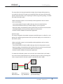
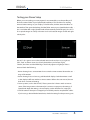
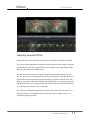
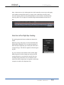
IRIDAS
SI-3D Workflow
Stereo 3D Workflow
with SI-3D files
© 2009 IRIDAS www.iridas.com
1
IRIDAS
SI-3D Workflow
DualStream 3.0
The 3rd generation of IRIDAS DualStream support for working with Stereo 3D material
includes support for virtually every display technology available today. A list of the most
common technologies and the required changes in your SpeedGrade setup starts this
section about using DualStream.
To take advantage of SpeedGrade’s capability to automatically load left and right eye
footage be sure to adopt one of the file naming conventions listed in the section after
the display setup scenario.
Finally the fun part: learn more about he 3D adjustment and stereo grading features in
the last section on using DualStream.
© 2009 IRIDAS www.iridas.com
2
IRIDAS
SI-3D Workflow
Stereo 3D Setup Scenarios
SpeedGrade XR and SpeedGrade DI can be used on either a single screen with both 3D
image and UI on one display, or as a dual monitor setup. A basic dual monitor setup
uses two monitors connected via 2 DVI outputs, the advanced dual monitor setup
utilises the NVIDIA QuadroFX SDI technology to allow for real time 10 bit output over
2x Single Link SDI. The NVIDIA QuadroFX SDI setup requires Windows XP32 or Windows
XP64 (OS X does not support this technology).
The best setup for Version 2009 depends on the display technology for the 3D display.
For all setups we recommend using NVIDIA driver 182.65
FAQ: do I need to enable the stereo settings in the NVIDIA Control Panel?
SpeedGrade can drive almost all current Stereo 3D display technologies directly, chang ing the NVIDIA settings is not required except for active shutter glasses that are directly
attached to the NVIDIA Stereo DIN connector and systems that require one DVI input
per channel.
3D DLP systems
Samsung and Mitsubishi both offer 3D DLP products. The monitors run at 120 Hz, sizes
vary between 48” and 73”.
To view stereoscopic content active shutter glasses are required. The stereo mode in
SpeedGrade to drive these monitors is called “pattern”, select it from the stereo mode
list in the application’s settings under Display.
JVC and Hyundai 3D TV systems
These 46” Stereo 3D Displays are line-by-line systems (interlaced scanline stereo).
Select “interlaced scanlines” in the stereo display mode selector under Settings/Display
to enable Stereo 3D viewing on the JVC and Hyundai 46”.
© 2009 IRIDAS www.iridas.com
3
IRIDAS
SI-3D Workflow
Dual DVI stereo
A number of stereo display setups require 2 DVI outputs from the workstation. Each
output carries one eye only. This applies to:
- Planar stereo screen (with passive glasses, linear polarization)
- Dual Projection (with passive glasses, linear or circular polarization)
- L/R side by side setups using 2 displays
Basic Dual DVI Setup: NVIDIA OpenGL Stereo
Requirements:
- Windows XP32 / XP64
- NVIDIA QuadroFX 5800
- certified driver for OpenGL Stereo (182.65)
This setup allows you to send left and right image to 2 separate DVI outputs. The user
interface will appear on the stereo output on both eyes. To enable OpenGL Stereo acces
the NVIDIA control panel, set both displays to NVIDIA clone mode. Then change the
following settings under “3D Performance Settings”:
- OpenGL Stereo: ON
- Tripple Buffering: ON
Restart the machine after making these changes. Then open the settings in SpeedGrade
(push “S”), choose Display. Select “Shutter Glasses” from the stereo pull-down menu.
Restart the application.
Advanced Dual DVI Setup: NVIDIA QuadroFX Dual SDI
plus BlackMagic HDLink Pro
Requirements:
- Windows XP32 / XP64
- NVIDIA QuadroFX 5800 SDI
- certified driver for QuadroFX SDI (182.65)
- 2x BlackMagic HDLink Pro
© 2009 IRIDAS www.iridas.com
4
IRIDAS
SI-3D Workflow
This setup allows for having discrete left and right channel output while preserving
one screen for GUI only. This setup is recommended if the main purpose for the setup
requires interactive work (such as adjusting the stereoscopy, stereo grading). To enable
this setup follow these steps:
- Make sure the SDI output is not activated by another application and not used to
mirror your desktop
- Connect the NVIDIA SDI with one BNC cable per channel to the HDLink Pros
- Connect each HDLink via DVI to your Planar display or your 2 projectors
- Open the settings in SpeedGrade, select SDI/Dual DVI, choose the correct resolution
and refresh frequency. In the pull-down below, choose Dual 4:2.2.
- Click the “Enable” checkbox and restart the application.
Dual SDI output
This setup is designed to drive either 2 projectors with SDI inputs or to allow for a com
bination of a reference grade monitor with any other 3D display such as the JVC 46” or
-
the 3D DLP systems.
- Make sure the SDI output is not activated by another application and not used to
mirror your desktop
- Connect the NVIDIA SDI with one BNC cable per channel to the projection system
- Open the settings in SpeedGrade, select SDI/Dual DVI, choose the correct resolution
and refresh frequency. In the pull-down below, choose Dual 4:2.2.
- Click the “Enable” checkbox and restart the application.
To combine Dual SDI with systems such as the JVC 46” and the 3D DLPs you’ll need a
unit such as Inition’s Stereobrain that can split the SDI signal as well as producing the
various output modes for the other systems in parallel (over DVI / HDMI)
- L or R
- L+R
- L-R
L
R
Workstation
NVIDIA Dual SDI
- Line-by-Line
- TI Pattern
- Anaglyph
Stereo Processor
(e.g. StereoBrain)
Reference grade system
plus Stereo Display
© 2009 IRIDAS www.iridas.com
5
IRIDAS
SI-3D Workflow
Testing your Stereo Setup
Before you start working on a new project it’s recommended to run the test file you’ll
find in the stereo folder of your SpeedGrade installation. This file allows for avoiding
inversed stereo settings on your display. To load the files, click the stereo checkbox on
the timeline. Then open the desktop, find the folder stereo in your SpeedGrade installa
-
tion. Load either left or right (SpeedGrade will automatically load both eyes). Hit <ALT +
D> to put the images in side-by-side view. You should see both images for left and right
side-by-side:
Hit <ALT + D> again to turn on the selected stereo mode and turn on your glasses.
“left”, “Dual” and the 4 arrows should only be visible to your left eye. “right”,
“Stream”, the 4 lines and the IRIDAS logo should only appear on right eye. If this is
inversed check the following:
- Active shutter glasses: some emitters have a switch to inverse stereo. Reverse the set tings of the emitter.
- Active shutter glasses on Samsung and Mitsubishi displays: both the emitter as well
as the display itself have switches to inverse stereo. Refer to the user manual, be sure
both don’t use inversed settings
- Passive systems (such as the JVC 46”): These systems don’t have a switch to inverse
stereo. If the image seems to be inverted, it’s easiest to swap eyes in the settings of
SpeedGrade. Open the settings, choose Display, use the checkbox for “swap eyes”.
- Dual SDI stereo: if the eyes are swapped you most likely need to swap the BNC cables.
If you’re using a device like the Stereobrain, check the settings for the processing unit.
© 2009 IRIDAS www.iridas.com
6
IRIDAS
SI-3D Workflow
Organizing Stereo 3D Footage
DualStream applications automatically find the corresponding footage for the other eye
when you drop a sequence into the timeline. In order for this to work, the sequences
need to use either one of the following naming conventions in the same position in their
fully qualified path:
t “left” and “right”
t “Left” and “Right”
t “LEFT” and “RIGHT”
t “_L” and “_R”
t “lf” and “rt”
t “LF” and “RT”
File Path Examples:
Scenario A: both left and right eye are on the same Volume:
t X:\Footage\left\Shot\Version\Test\frame#.siv
X:\Footage\right\Shot\Version\Test\frame#.siv
t X:\Footage\left_eye\Shot\Version\Test\frame#.siv
X:\Footage\right_eye\Shot\Version\Test\frame#.siv
t X:\Footage\left\Shot\Version\Test_L\frame#.siv
X:\Footage\right\Shot\Version\Test_R\frame#.siv
t X:\Footage\left\Shot\Version\Test\left#.siv
X:\Footage\right\Shot\Version\right#.siv
© 2009 IRIDAS www.iridas.com
7
IRIDAS
SI-3D Workflow
Scenario B: left and right eye are stored on 2 discrete Volumes:
Running OS X please ensure to use Volume Names LEFT and RIGHT. Running Windows
please use R:\ and L:\ drive letters.
t L:\Footage\Shot\Version\Test\frame#.siv
t R:\Footage\Shot\Version\Test\frame#.siv
Note: Make sure you don’t have any of the replacement wildcards as part of your regu
lar filename, otherwise they will be replaced. These examples would not work:
-
t X:\Footage\left\Shot\Version\Test\Compositing_Shot_left_Lowres.#.dpx
t X:\Footage\right\Shot\Version\Test\Compositing_Shot_right_Lowres.#.dpx
(The _L in the left eye filename’s _Lowres would be substituted with _R, and result in
right right_Rowres.#.dpx which cannot be found)
© 2009 IRIDAS www.iridas.com
8
IRIDAS
SI-3D Workflow
Working with Stereo 3D Footage
To work with a stereo timeline, enable the Stereo check box in the timeline.
Now use the desktop to add a shot or multiple shots from
either left or right eye branch to a new timeline. The cor responding other eye will automatically be loaded.
Note: If you mainly work in stereo, you can change the
default for new timelines by checking the “Enable Stereo”
checkbox in the Editing settings. Now newly created
timelines are stereoscopic by default.
Applying Basic Stereo Parameters
Verify left and right eye pairs
To verify that both eyes are loaded, open the Reel
Browser (ALT + R or CP200 TS [More]+[Reels]) .
Each shot that you add to the timeline will appear as left
and right eye pair.
Adjust the basic stereo parameters next. If the footage
is recorded with a side-by-side rig, you can skip the next
step.
Adjust horizontal and vertical mirror
If the footage is recorded with a mirror rig, invert the
horizontal or vertical mirroring with the checkboxes in the
Reel Browser. Check the footage to see which eye needs
the inversion.
© 2009 IRIDAS www.iridas.com
9
IRIDAS
SI-3D Workflow
Tip: If the majority of your clips is flipped,
you can change the defaults before add ing them to the timeline. Open the Set tings (press <S>), select Editing. Use the
checkboxes for vertical or horizontal mir roring. All clips you add to a timeline after
changing these presets will be loaded
flipped according to your new settings.
You can still make changes in the Reel
Browser after your have added the clips.
Swap eyes
If one of your reels has swapped left and
right eye, you can correct for this with
the Left / Right swap button. Hover the
mouse over the reel you want to swap,
the L<->R button becomes visible. Click it
to swap eyes.
Note: Make sure your display is set up
correctly. The easiest way to verify this
is to load the left/right clip available in
stereo subdirectory of your program
installation. If left/right are reversed, flip
the eyes in the display setup as discussed
in the previous chapter.
© 2009 IRIDAS www.iridas.com
10
IRIDAS
SI-3D Workflow
Adjusting Temporal Offsets
A temporal offset occurs when the cameras were not started at exactly the same time.
It is easiest to make adjustments for temporal offsets while the stereo image is displayed
side-by-side. Press Alt+D to toggle side-by-side and regular stereo view. Keep the Reel
Browser open and close all other browsers.
Play the shot you want to adjust. If there’s a clapperboard at the beginning or end of
the shot, play until you see the clapperboard closed in either left or right eye. Use frame
step forward and backward (left and right arrow keys) to get this narrowed down. Iden tify how many frames offset exist between left and right eye. You can interactively move
the offset by clicking and dragging the spinner button to the right of the offset edit box.
In our example, you’d have to set +1 for left eye.
Tip: if there’s no clapperboard present, find a frame with action that only lasts for one
frame. If possible, use a clapperboard with time code display to help the process of
straightening temporal offsets.
© 2009 IRIDAS www.iridas.com
11
IRIDAS
SI-3D Workflow
Basic Color Adjustments
Make sure to apply RAW adjustments before you start working on 3D color adjust ments.
The example images used for this document are recorded with 2 SI2K cameras as Cine
form RAW. For this workflow simply open the .Look browser, select the 5600 or 3200K
-
preset.
All RAW adjustments should be applied to the basic video layer. This will ensure that
they will get applied to both left and right eye automatically.
For all adjustments on grading tracks above the video layer you can select whether
you want to apply the changes to both or left or right eye only. A typical example for
selected left or right eye grading is the adjustment for chroma and luma shifts created
by the mirror in a mirror rig.
To see left and right eye
side-by-side press < ALT +
D >. You can then turn on
splitscreen (press F9 or open
the Screen Layout window
and make adjustments
there).
© 2009 IRIDAS www.iridas.com
12
IRIDAS
SI-3D Workflow
Note: adjustments such as dealing with color shifts created by a mirror rig usually apply
to all material coming off the same rig / camera / lens combination. Shooting a test
chart and creating a precise .look preset will help to save time when correcting for the
mirror rig shifts. You can apply one .look file along the entire timeline to take care of
this.
Selective Left or Right Eye Grading
The grading panel will show an additional selection for
Stereo.
With every new grading clip you add to the timeline the
default will be “Both eyes”. You can easily change this to
either Left eye or Right eye, just use the pull-down menu
to apply changes. The selection applies to the entire grad ing clip.
Tip: If you want to work with the same mask but apply
different grades for left and right eye, simply start with
creating the mask on one clip, then copy this clip onto
another grading track above. You now have the same
mask twice at the same position and grades can be made
to appear on either Left or Right eye only.
© 2009 IRIDAS www.iridas.com
13
IRIDAS
SI-3D Workflow
Stereo 3D Adjustments
SpeedGrade’s Pan & Scan technology includes a section that allows for adjusting
Zero Parallax, rotation as well as horizontal offset. Please check the chapter on working
with Pan & Scan to get to know the basic tools of the Pan & Scan Panel.
Adjusting Geometry Offsets
It is easiest to make adjustments for geometry offsets
while the stereo image is displayed in red/cyan or differ ence matte. Both modes can be accessed via the stereo
settings pull-down (press < S >, select Display).
To get started add a Pan & Scan track to your timeline.
This is a global track, to make adjustments for a specific
clip, go to the first frame of the clip, then add a keyframe
to the Pan & Scan track.
Turn on the stereo adjustment options to the right in your Pan & Scan Panel.
Once turned on, they will mirror all changes you apply via numerical input or the widget
for left and right eye. This reduces the loss of quality to the absolute minimum as op posed to making geometry changes on eye only.
© 2009 IRIDAS www.iridas.com
14
IRIDAS
SI-3D Workflow
Identify the geometry offsets in the image, it’s usually helpful to reduce the parallax first
by moving the widget until you see the main objects on the image overlapping:
Original image in difference
map view: rotation and
Step 1: change the horizon tal offset with the widget
Step 2: change rotation
and vertical offset until
horizontal offset are hard
to judge.
to reduce the 0 parallax.
Use Tangent controls on
the Wave or the CP200 BK
to get easy access to x and
you see a minimum offset
across the image. If in
doubt, focus on the main
objects. Then set back the
y parameters
horizontal offset to return
to original parallax
Image after changing
geometry offsets
© 2009 IRIDAS www.iridas.com
15
IRIDAS
SI-3D Workflow
Adjusting the Zero Parallax
You can continue to work with the same Pan & Scan track you used to work on rotation
and vertical offset, just be sure the checkbox for mirroring horizontal offset (= Zero
Parallax) is checked.
Alternatively create another Pan & Scan track above the current layer, so you can be sure
to not touch other geometry adjustments you made already.
Tip: Copy the first Pan & Scan track after creating keyframes along the
edits. You can then use one layer for rotation and vertical offsets, one
layer for Zero Parallax without creating keyframes twice. To copy a Pan
& Scan track use Ctrl + left mouse over the handle icon at the begin
ning of the Pan & Scan track
-
© 2009 IRIDAS www.iridas.com
16