1
Safety Summary
When you notice any of the unusual conditions listed below, immediately
terminate operation and disconnect the power cable.
Contact your local Agilent Technologies sales representative or
authorized service company for repair of the instrument. If you continue
to operate without repairing the instrument, there is a potential fire or
shock hazard for the operator.
n Instrument operates abnormally.
n Instrument emits abnormal noise, smell, smoke or a spark-like light
during the operation.
n Instrument generates high temperature or electrical shock during
operation.
n Power cable, plug, or receptacle on instrument is damaged.
n Foreign substance or liquid has fallen into the instrument.
Caution
Do not exceed the operating input power, voltage, and current
level and signal type appropriate for the instrument being used, refer to
your instrument's Function Reference.
Electrostatic discharge(ESD) can damage the highly sensitive
microcircuits in your instrument. ESD damage is most likely to occur as
the test fixtures are being connected or disconnected. Protect them from
ESD damage by wearing a grounding strap that provides a high
resistance path to ground. Alternatively, ground yourself to discharge any
static charge built-up by touching the outer shell of any grounded
instrument chassis before touching the test port connectors..
4352B
Agilent 4352B VCO/PLL Signal Analyzer
Function Reference
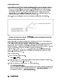
SERIAL NUMBERS
This manual applies directly to instruments that have the rmware revision
2.x. For additional information about rmware revisions, see in Appendix A.
Agilent Part No. 04352-90090
Printed in JAPAN July 2003
Eighth Edition
Notice
The information contained in this document is subject to change without notice.
This document contains proprietary information that is protected by copyright. All rights are
reserved. No part of this document may be photocopied, reproduced, or translated to another
language without the prior written consent of the Agilent Technologies.
Agilent Technologies Japan, Ltd.
Component Test PGU-Kobe
1-3-2, Murotani, Nishi-ku, Kobe-shi,
Hyogo, 651-2241 Japan
c Copyright 1997, 1998, 1999, 2001, 2003 Agilent Technologies Japan, Ltd.
Manual Printing History
The manual's printing date and part number indicate its current edition. The printing date
changes when a new edition is printed. (Minor corrections and updates that are incorporated
at reprint do not cause the date to change.) The manual part number changes when extensive
technical changes are incorporated.
June 1997 : : : : : : : : : : : : : : : : : : : : : : : : : : : : : : : : : : : : : : : : : : : : First Edition (part number: 04352-90040)
September 1998 : : : : : : : : : : : : : : : : : : : : : : : : : : : : : : : : : : : Second Edition (part number: 04352-90050)
February 1999 : : : : : : : : : : : : : : : : : : : : : : : : : : : : : : : : : : : : : : : Third Edition (part number: 04352-90060)
July 1999 : : : : : : : : : : : : : : : : : : : : : : : : : : : : : : : : : : : : : : : : : : Fourth Edition (part number: 04352-90070)
December 1999 : : : : : : : : : : : : : : : : : : : : : : : : : : : : : : : : : : : : : : Fifth Edition (part number: 04352-90070)
January 2001 : : : : : : : : : : : : : : : : : : : : : : : : : : : : : : : : : : : : : : : : Sixth Edition (part number: 04352-90070)
December 2001 : : : : : : : : : : : : : : : : : : : : : : : : : : : : : : : : : : : Seventh Edition (part number: 04352-90080)
July 2003 : : : : : : : : : : : : : : : : : : : : : : : : : : : : : : : : : : : : : : : : : : Eighth Edition (part number: 04352-90090)
iii
Safety Summary
The following general safety precautions must be observed during all phases of operation,
service, and repair of this instrument. Failure to comply with these precautions or with specic
WARNINGS elsewhere in this manual may impair the protection provided by the equipment.
In addition it violates safety standards of design, manufacture, and intended use of the
instrument.
The Agilent Technologies assumes no liability for the customer's failure to comply with these
requirements.
Note
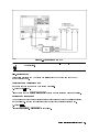
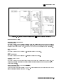
4352B comply with INSTALLATION CATEGORY II and POLLUTION DEGREE 2
in IEC1010-1. 4352B are INDOOR USE product.
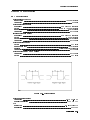
Note
LEDs in 4352B are Class 1 in accordance with IEC825-1.
CLASS 1 LED PRODUCT
Ground The Instrument
To avoid electric shock hazard, the instrument chassis and cabinet must be connected to a
safety earth ground by the supplied power cable with earth blade.
DO NOT Operate In An Explosive Atmosphere
Do not operate the instrument in the presence of ammable gasses or fumes. Operation of any
electrical instrument in such an environment constitutes a denite safety hazard.
Keep Away From Live Circuits
Operating personnel must not remove instrument covers. Component replacement and internal
adjustments must be made by qualied maintenance personnel. Do not replace components
with the power cable connected. Under certain conditions, dangerous voltages may exist even
with the power cable removed. To avoid injuries, always disconnect power and discharge
circuits before touching them.
DO NOT Service Or Adjust Alone
Do not attempt internal service or adjustment unless another person, capable of rendering rst
aid and resuscitation, is present.
DO NOT Substitute Parts Or Modify Instrument
Because of the danger of introducing additional hazards, do not install substitute parts or
perform unauthorized modications to the instrument. Return the instrument to a Agilent
Technologies Sales and Service Oce for service and repair to ensure that safety features are
maintained.
iv
Dangerous Procedure Warnings
Warnings , such as the example below, precede potentially dangerous procedures throughout
this manual. Instructions contained in the warnings must be followed.
Warning
Dangerous voltages, capable of causing death, are present in this
instrument. Use extreme caution when handling, testing, and adjusting
this instrument.
v
Typeface Conventions
Bold
Italics
Computer
4HARDKEYS5
NNNNNNNNNNNNNNNNNNNNNNNNNN
SOFTKEYS
vi
Boldface type is used when a term is dened. For example: icons are
symbols.
Italic type is used for emphasis and for titles of manuals and other
publications.
Italic type is also used for keyboard entries when a name or a variable
must be typed in place of the words in italics. For example: copy
lename means to type the word copy, to type a space, and then to
type the name of a le such as file1.
Computer font is used for on-screen prompts and messages.
Labeled keys on the instrument front panel are enclosed in 4 5.
Softkeys located to the right of the LCD are enclosed in .
NNNNN
Certication
Agilent Technologies certies that this product met its published specications at the time
of shipment from the factory. Agilent Technologies further certies that its calibration
measurements are traceable to the United States National Institute of Standards and
Technology, to the extent allowed by the Institution's calibration facility, or to the calibration
facilities of other International Standards Organization members.
Documentation Warranty
The material contained in this document is provided \as is," and is subject to being changed,
without notice, in future editions. Further, to the maximum extent permitted by applicable
law, Agilent disclaims all warranties, either express or implied with regard to this manual
and any information contained herein, including but not limited to the implied warranties of
merchantability and tness for a particular purpose. Agilent shall not be liable for errors or for
incidental or consequential damages in connection with the furnishing, use, or performance
of this document or any information contained herein. Should Agilent and the user have a
separate written agreement with warranty terms covering the material in this document that
conict with these terms, the warranty terms in the separate agreement will control.
Exclusive Remedies
The remedies provided herein are buyer's sole and exclusive remedies. Agilent Technologies
shall not be liable for any direct, indirect, special, incidental, or consequential damages,
whether based on contract, tort, or any other legal theory.
Assistance
Product maintenance agreements and other customer assistance agreements are available for
Agilent Technologies products.
For any assistance, contact your nearest Agilent Technologies Sales and Service Oce.
Addresses are provided at the back of this manual.
vii
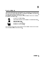
Safety Symbols
General denitions of safety symbols used on equipment or in manuals are listed below.
Instruction manual symbol: the product is marked with this symbol when it is
necessary for the user to refer to the instruction manual.
Alternating current.
Direct current.
On (Supply).
O (Supply).
In position of push-button switch.
Out position of push-button switch.
Frame (or chassis) terminal. A connection to the frame (chassis) of the
equipment which normally include all exposed metal structures.
This Warning sign denotes a hazard. It calls attention to a procedure, practice,
condition or the like, which, if not correctly performed or adhered to, could
result in injury or death to personnel.
This Caution sign denotes a hazard. It calls attention to a procedure, practice,
condition or the like, which, if not correctly performed or adhered to, could
result in damage to or destruction of part or all of the product.
This Note sigh denotes important information. It calls attention to a
procedure, practice, condition or the like, which is essential to highlight.
Axed to product containing static sensitive devices use anti-static handling
procedures to prevent electrostatic discharge damage to component.
viii
In This Book
This reference is organized as follows:
Chapter 1
Gives you an overview of the analyzer (4352B VCO/PLL Signal Analyzer).
Chapter 2
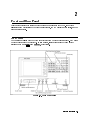
Illustrates the front and rear panels of 4352B.
Chapter 3
Describes what to verify when opening the package and how to install your 4352B.
Chapter 4
Provides a tutorial guide for measuring VCOs and PLLs with the 4352B.
Chapter 5
Explains basic procedures to measure VCOs and PLLs using the 4352B and the 43521A (
Downconverter Unit).
Chapter 6
Explains the functions accessible via the ENTRY block.
Chapter 7
Explains the functions accessible via the MEASUREMENT block when the analyzer operates
in the tester mode.
Chapter 8
Explains the functions accessible via the MEASUREMENT block when the analyzer operates
in the analyzer mode.
Chapter 9
Explains the functions accessible via the CONTROL block.
Chapter 10
Explains the functions accessible via the INSTRUMENT STATE block.
Chapter 11
Lists the specications of the 4352B.
Appendix A
Contains the information required to adapt this manual to earlier versions or congurations
of the analyzer than the current printing date of this manual.
Appendix B
Provides an overview of GPIB and its functions available with the 4352B.
Appendix C
Provides additional information on the phase noise vs. oset frequency measurements and
frequency transient measurements.
Appendix D
Contains an overview of the save/recall function and the information required when you use
a data le stored with the save function.
Appendix E
Lists input ranges, preset values, and power ON default settings.
Appendix F
Helps you perform a quick guide diagnosis of your 4352B.
ix
Document Guide
Please utilize the following manuals when using the analyzer:
Function Reference
Describes basic operations of this instrument and the 43521A (Downconverter Unit) and
all the functions called from the front panel keys and softkeys. It also provides
information on options and accessories available, specications, system performance,
and conceptual information about the analyzer's features.
GPIB Programming Manual
Describes basic programming to remote-control this instrument and the 43521A (
Downconverter Unit) using GPIB. Also, contains information on the usage of all GPIB
commands, the status report mechanism, and the data transmission format.
Manual Supplement for Instrument BASIC Users Handbook
Describes how Instrument BASIC works with the analyzer.
Instrument BASIC User's Handbook
Explains the usage of Instrument BASIC including general programming examples and
hints. Also, explains all Instrument BASIC commands. This manual consists of the
following three parts: \Instrument BASIC Programming Technique," \Instrument BASIC
Interface Technique," and \Instrument BASIC Language Reference."
43521A Operation Manual
Describes the accessories of the 43521A (Downconverter Unit), connection to the 4352B
(VCO/PLL signal analyzer), conguration of the front and rear panels, and specications.
Details on how to operate the 43521A are described in the 4352B Function Reference.
x
If A Problem Is Suspected
If any kind of failure is observed in the operation of the analyzer, or in the operation of a
measurement system that includes the analyzer, please see Appendix F. Appendix F is a
quick fault diagnosis guide for the analyzer. By performing the diagnostics according to the
instructions provided, the faulty instrument can be pinpointed in a short time.
Also, when an error message is displayed on the analyzer's LCD screen, please see \Error
Messages" at the back of the manual.
xi
Contents
1. Introduction
Analyzer's Features . . . . .
Front and Rear Panel . . .
ENTRY Block . . . . . . .
MEASUREMENT Block . . .
CONTROL Block . . . . . .
INSTRUMENT STATE Block
.
.
.
.
.
.
.
.
.
.
.
.
.
.
.
.
.
.
.
.
.
.
.
.
.
.
.
.
.
.
.
.
.
.
.
.
.
.
.
.
.
.
.
.
.
.
.
.
.
.
.
.
.
.
.
.
.
.
.
.
.
.
.
.
.
.
.
.
.
.
.
.
.
.
.
.
.
.
.
.
.
.
.
.
.
.
.
.
.
.
.
.
.
.
.
.
.
.
.
.
.
.
.
.
.
.
.
.
.
.
.
.
.
.
.
.
.
.
.
.
.
.
.
.
.
.
.
.
.
.
.
.
.
.
.
.
.
.
.
.
.
.
.
.
1-2
1-2
1-2
1-2
1-3
1-3
2. Front and Rear Panel
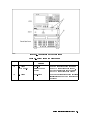
Front Panel . . . . . . . . . . . . . . . . . . . . . . .
1. Front Panel Keys and Softkeys . . . . . . . . . . . .
Softkeys that are Connected with Vertical Lines . . . .
Softkeys That Toggle On or O . . . . . . . . . . . .
Softkeys that Show Status Indications in Brackets . . .
2. GPIB REMOTE Indicator . . . . . . . . . . . . . . .
3. 4Preset5 key . . . . . . . . . . . . . . . . . . . . .
4. LO IN (LO Input) Connector . . . . . . . . . . . . .
5. RF IN (RF Input) Connector . . . . . . . . . . . . .
6. DC POWER (Power Voltage) Output Connector . . . .
7. DC CONTROL (Control Voltage) Output Connector
8. MOD OUT (Modulation Signal Output) Connector . . .
9. Built-In Flexible Disk Drive . . . . . . . . . . . . .
10. LINE Switch . . . . . . . . . . . . . . . . . . . .
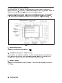
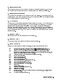
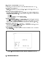
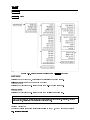
Screen Display (Tester Mode) . . . . . . . . . . . . . . .
1. Measurement Item . . . . . . . . . . . . . . . . .
2. Automatic Frequency Control ON/OFF . . . . . . . .
3. Softkey Labels . . . . . . . . . . . . . . . . . . .
4. Measurement Time . . . . . . . . . . . . . . . . .
5. Measurement Parameters . . . . . . . . . . . . . .
6. LO Frequency . . . . . . . . . . . . . . . . . . .
7. Memory Content . . . . . . . . . . . . . . . . . .
8. Measured Value . . . . . . . . . . . . . . . . . . .
9. Status Notations . . . . . . . . . . . . . . . . . .
10. Message Area . . . . . . . . . . . . . . . . . . .
11. Title . . . . . . . . . . . . . . . . . . . . . . .
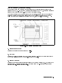
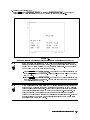
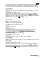
Screen Display (Analyzer Mode) . . . . . . . . . . . . .
1. Measurement Item . . . . . . . . . . . . . . . . .
2. DIV/REF . . . . . . . . . . . . . . . . . . . . . .
3. Marker Reading . . . . . . . . . . . . . . . . . . .
4. Softkey Labels . . . . . . . . . . . . . . . . . . .
5. PASS/FAIL . . . . . . . . . . . . . . . . . . . . .
6. Carrier Frequency . . . . . . . . . . . . . . . . .
7. Measurement Parameters . . . . . . . . . . . . . .
8. Status Notations . . . . . . . . . . . . . . . . . .
9. Message Area . . . . . . . . . . . . . . . . . . . .
.
.
.
.
.
.
.
.
.
.
.
.
.
.
.
.
.
.
.
.
.
.
.
.
.
.
.
.
.
.
.
.
.
.
.
.
.
.
.
.
.
.
.
.
.
.
.
.
.
.
.
.
.
.
.
.
.
.
.
.
.
.
.
.
.
.
.
.
.
.
.
.
.
.
.
.
.
.
.
.
.
.
.
.
.
.
.
.
.
.
.
.
.
.
.
.
.
.
.
.
.
.
.
.
.
.
.
.
.
.
.
.
.
.
.
.
.
.
.
.
.
.
.
.
.
.
.
.
.
.
.
.
.
.
.
.
.
.
.
.
.
.
.
.
.
.
.
.
.
.
.
.
.
.
.
.
.
.
.
.
.
.
.
.
.
.
.
.
.
.
.
.
.
.
.
.
.
.
.
.
.
.
.
.
.
.
.
.
.
.
.
.
.
.
.
.
.
.
.
.
.
.
.
.
.
.
.
.
.
.
.
.
.
.
.
.
.
.
.
.
.
.
.
.
.
.
.
.
.
.
.
.
.
.
.
.
.
.
.
.
.
.
.
.
.
.
.
.
.
.
.
.
.
.
.
.
.
.
.
.
.
.
.
.
.
.
.
.
.
.
.
.
.
.
.
.
.
.
.
.
.
.
.
.
.
.
.
.
.
.
.
.
.
.
.
.
.
.
.
.
.
.
.
.
.
.
.
.
.
.
.
.
.
.
.
.
.
.
.
.
.
.
.
.
.
.
.
.
.
.
.
.
.
.
.
.
.
.
.
.
.
.
.
.
.
.
.
.
.
.
.
.
.
.
.
.
.
.
.
.
2-1
2-2
2-2
2-2
2-2
2-2
2-3
2-3
2-3
2-3
2-3
2-3
2-3
2-3
2-4
2-4
2-4
2-4
2-5
2-5
2-5
2-5
2-5
2-5
2-6
2-6
2-7
2-7
2-7
2-7
2-8
2-8
2-8
2-8
2-8
2-8
Contents-1
10. Title . . . . . . . . . . . . . . . . . .
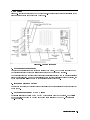
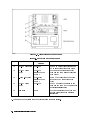
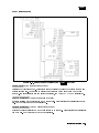
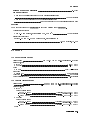
Rear Panel . . . . . . . . . . . . . . . . . .
1. External Reference Input . . . . . . . . .
2. Internal Reference Output . . . . . . . . .
3. External Program RUN/CONT Input . . . .
4. I/O Port . . . . . . . . . . . . . . . . .
5. Inlet (with fuse box) . . . . . . . . . . .
6. GPIB Interface . . . . . . . . . . . . . .
7. External Monitor Terminal . . . . . . . . .
8. Parallel Interface Connector . . . . . . . .
9. 24 Bit I/O Interface . . . . . . . . . . . .
10. mini-DIN Keyboard Connector . . . . . .
11. External Trigger Input . . . . . . . . . .
12. 40 MHz Output Connector . . . . . . . .
13 and 14. Second IF Input/Output Connectors
.
.
.
.
.
.
.
.
.
.
.
.
.
.
.
.
.
.
.
.
.
.
.
.
.
.
.
.
.
.
.
.
.
.
.
.
.
.
.
.
.
.
.
.
.
.
.
.
.
.
.
.
.
.
.
.
.
.
.
.
.
.
.
.
.
.
.
.
.
.
.
.
.
.
.
.
.
.
.
.
.
.
.
.
.
.
.
.
.
.
.
.
.
.
.
.
.
.
.
.
.
.
.
.
.
.
.
.
.
.
.
.
.
.
.
.
.
.
.
.
.
.
.
.
.
.
.
.
.
.
.
.
.
.
.
.
.
.
.
.
.
.
.
.
.
.
.
.
.
.
.
.
.
.
.
.
.
.
.
.
.
.
.
.
.
.
.
.
.
.
.
.
.
.
.
.
.
.
.
.
.
.
.
.
.
.
.
.
.
.
.
.
.
.
.
.
.
.
.
.
.
.
.
.
.
.
.
.
.
.
.
.
.
.
.
.
.
.
.
.
.
.
.
.
.
2-8
2-9
2-9
2-9
2-9
2-10
2-10
2-10
2-10
2-10
2-10
2-10
2-10
2-10
2-10
3. Installation and Setup Guide
Incoming Inspection . . . . . . . . . . . . . . . . .
Contents . . . . . . . . . . . . . . . . . . . . . .
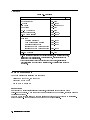
Power Requirements . . . . . . . . . . . . . . . . .
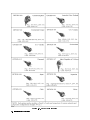
Power Cable . . . . . . . . . . . . . . . . . . . .
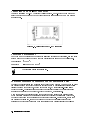
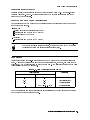
Replacing Fuse . . . . . . . . . . . . . . . . .
Fuse Selection . . . . . . . . . . . . . . . . . . .
Replacing Fuse . . . . . . . . . . . . . . . . . .
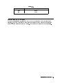
Connecting the BNC-BNC connector . . . . . . . . .
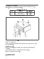
Operation Environment . . . . . . . . . . . . . . .
Providing clearance to dissipate heat at installation site
Instruction for Cleaning . . . . . . . . . . . . . . .
Rack/Handle Installation . . . . . . . . . . . . . . .
Option 1CN Handle Kit . . . . . . . . . . . . . . .
Installing the Handle . . . . . . . . . . . . . . .
Option 1CM Rack Mount Kit . . . . . . . . . . . .
Mounting the Rack . . . . . . . . . . . . . . . .
Option 1CP Rack Mount & Handle Kit . . . . . . . .
Mounting the Handle and Rack . . . . . . . . . .
.
.
.
.
.
.
.
.
.
.
.
.
.
.
.
.
.
.
.
.
.
.
.
.
.
.
.
.
.
.
.
.
.
.
.
.
.
.
.
.
.
.
.
.
.
.
.
.
.
.
.
.
.
.
.
.
.
.
.
.
.
.
.
.
.
.
.
.
.
.
.
.
.
.
.
.
.
.
.
.
.
.
.
.
.
.
.
.
.
.
.
.
.
.
.
.
.
.
.
.
.
.
.
.
.
.
.
.
.
.
.
.
.
.
.
.
.
.
.
.
.
.
.
.
.
.
.
.
.
.
.
.
.
.
.
.
.
.
.
.
.
.
.
.
.
.
.
.
.
.
.
.
.
.
.
.
.
.
.
.
.
.
.
.
.
.
.
.
.
.
.
.
.
.
.
.
.
.
.
.
.
.
.
.
.
.
.
.
.
.
.
.
.
.
.
.
.
.
.
.
.
.
.
.
.
.
.
.
.
.
.
.
.
.
.
.
3-1
3-2
3-2
3-2
3-5
3-5
3-5
3-6
3-6
3-6
3-7
3-8
3-8
3-8
3-9
3-9
3-9
3-9
4. Basic Measurement Procedures
Introduction . . . . . . . . . . . . . . . . . . . . . . . . . . .
Measurement Overview . . . . . . . . . . . . . . . . . . . .
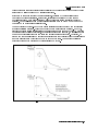
Device Characteristics . . . . . . . . . . . . . . . . . . . . .
Voltage Control Oscillator (VCO): . . . . . . . . . . . . . . .
Phase Locked Loop (PLL): . . . . . . . . . . . . . . . . . .
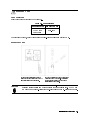
Required Equipment . . . . . . . . . . . . . . . . . . . . . .
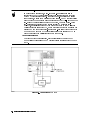
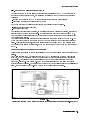
1. Cable Connection . . . . . . . . . . . . . . . . . . . . . . .
2. Power ON . . . . . . . . . . . . . . . . . . . . . . . . . .
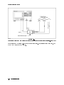
3. Connecting Device . . . . . . . . . . . . . . . . . . . . . .
4. Initial Setup . . . . . . . . . . . . . . . . . . . . . . . . .
4-1. Verifying GPIB Controller Mode . . . . . . . . . . . . . .
4-2. Setting Up to Control the External Signal Generator via GPIB
4-3. Specifying DC Power Voltage . . . . . . . . . . . . . . . .
5. Selecting Measurement Mode . . . . . . . . . . . . . . . . .
6. Measurements in Tester Mode . . . . . . . . . . . . . . . . .
6-1. Specifying DC Control Voltage . . . . . . . . . . . . . . .
6-2. Applying DC Voltages . . . . . . . . . . . . . . . . . . .
.
.
.
.
.
.
.
.
.
.
.
.
.
.
.
.
.
.
.
.
.
.
.
.
.
.
.
.
.
.
.
.
.
.
.
.
.
.
.
.
.
.
.
.
.
.
.
.
.
.
.
.
.
.
.
.
.
.
.
.
.
.
.
.
.
.
.
.
.
.
.
.
.
.
.
.
.
.
.
.
.
.
.
.
.
.
.
.
.
.
.
.
.
.
.
.
.
.
.
.
.
.
4-1
4-5
4-5
4-5
4-5
4-6
4-7
4-8
4-9
4-11
4-11
4-11
4-12
4-13
4-14
4-14
4-15
Contents-2
6-3. RF Power Measurement . . . . . . . . . . . . . . . . . . . . . . . . 4-15
6-4. Frequency Measurement . . . . . . . . . . . . . . . . . . . . . . . . 4-16
6-5. DC Power Current Measurement . . . . . . . . . . . . . . . . . . . . 4-16
6-6. FM Deviation Measurement . . . . . . . . . . . . . . . . . . . . . . 4-16
6-7. C/N Ratio (Carrier/Noise) . . . . . . . . . . . . . . . . . . . . . . . 4-18
Advanced Measurement Items in Tester Mode . . . . . . . . . . . . . . . . . 4-20
6-8. S/N Ratio . . . . . . . . . . . . . . . . . . . . . . . . . . . . . . . 4-20
6-9. Tuning Sensitivity Measurement (With Two Measurement Points) . . . . . 4-21
7. Measurements in Analyzer Mode . . . . . . . . . . . . . . . . . . . . . . 4-22
7-1. Specifying DC Control Voltage . . . . . . . . . . . . . . . . . . . . . 4-22
7-2. Applying DC Voltages . . . . . . . . . . . . . . . . . . . . . . . . . 4-23
7-3. RF Power Characteristic vs. DC Control Voltage (Target Device: VCO) . . 4-24
7-4. Frequency/Tuning Sensitivity Characteristics vs. DC Control Voltage (Target
Device: VCO) . . . . . . . . . . . . . . . . . . . . . . . . . . . . . 4-26
7-5. Phase Noise Characteristics vs. Oset Frequency (Target Device: VCO or
PLL) . . . . . . . . . . . . . . . . . . . . . . . . . . . . . . . . . . 4-29
7-6. Frequency Transient (Target Device: PLL) . . . . . . . . . . . . . . . 4-31
7-7. Spectrum (Target Device: VCO or PLL) . . . . . . . . . . . . . . . . . 4-33
Advanced Measurement Items in Analyzer Mode . . . . . . . . . . . . . . . . 4-35
7-8. Comparison between Carrier and Harmonic Levels . . . . . . . . . . . 4-35
7-9. Comparison Between Characteristics Obtained Under Three or Four
Dierent Conditions . . . . . . . . . . . . . . . . . . . . . . . . . . 4-37
7-10. Integral of Phase Noise vs. Oset Frequency Characteristics (Target
Device: VCO or PLL) . . . . . . . . . . . . . . . . . . . . . . . . . . 4-39
Partial integration . . . . . . . . . . . . . . . . . . . . . . . . . . . . . 4-41
7-11. Post-tuning Drift Characteristics . . . . . . . . . . . . . . . . . . . 4-42
7-12. Observation of FM Signal Waveform After Demodulation . . . . . . . . 4-44
Measurement Technique . . . . . . . . . . . . . . . . . . . . . . . . . . . 4-45
Setting the Automatic Frequency Control Function . . . . . . . . . . . . . 4-45
Setting Cable Loss Compensation Function . . . . . . . . . . . . . . . . . 4-48
5. Basic Measurements Using the 43521A
Introduction . . . . . . . . . . . . . . . . . . . . . . . . . . . . . . . . .
Measurement Items Available in Tester Mode . . . . . . . . . . . . . . . .
Measurement Items Available in Analyzer Mode . . . . . . . . . . . . . . .
1. Preparations for Measurements . . . . . . . . . . . . . . . . . . . . . .
1-1. Connecting Devices . . . . . . . . . . . . . . . . . . . . . . . . . .
1-2. Power ON . . . . . . . . . . . . . . . . . . . . . . . . . . . . . .
1-3. Connecting a DUT . . . . . . . . . . . . . . . . . . . . . . . . . . .
1-4. Initial Setup . . . . . . . . . . . . . . . . . . . . . . . . . . . . .
Verifying GPIB Controller Mode . . . . . . . . . . . . . . . . . . . . . .
Setting the Trigger Mode . . . . . . . . . . . . . . . . . . . . . . . . .
1-5. Setting the Downconverter Unit . . . . . . . . . . . . . . . . . . . .
1-6. Setting the External Signal Source and Frequency Band . . . . . . . . .
Setting the GPIB Address . . . . . . . . . . . . . . . . . . . . . . . . .
Setting the External Signal Source Automatic Setting Function . . . . . . .
Setting the Type of the External Signal Source and the Frequency Change Wait
Time . . . . . . . . . . . . . . . . . . . . . . . . . . . . . . . . .
Setting the Maximum Frequency of the External Signal Source . . . . . . .
Setting the Frequency Band . . . . . . . . . . . . . . . . . . . . . . .
Setting NOMINAL FREQ . . . . . . . . . . . . . . . . . . . . . . . . .
1-7. Specifying DC Power Voltage . . . . . . . . . . . . . . . . . . . . . .
1-8. Specifying DC Control Voltage and Wait Time . . . . . . . . . . . . . .
1-9. Applying Power Voltage and Control Voltage . . . . . . . . . . . . . .
2. Measurements in Tester Mode . . . . . . . . . . . . . . . . . . . . . . .
5-1
5-1
5-1
5-2
5-2
5-5
5-5
5-7
5-7
5-7
5-8
5-8
5-8
5-8
5-8
5-9
5-9
5-10
5-10
5-10
5-11
5-12
Contents-3
2-1. RF Power Measurement (DUT: VCO) . . . . . . . . . . . . . . . . . .
2-2. Frequency Measurement (DUT: VCO) . . . . . . . . . . . . . . . . . .
2-3. C/N (Carrier/Noise) Ratio Measurement (DUT: VCO) . . . . . . . . . . .
3. Measurements in Analyzer Mode . . . . . . . . . . . . . . . . . . . . . .
3-1. RF Power vs. DC Control Voltage Characteristics Measurement (DUT: VCO)
3-2. Frequency/Tuning Sensitivity vs. DC Control Voltage Characteristics
Measurement (DUT: VCO) . . . . . . . . . . . . . . . . . . . . . . . .
3-3. Phase Noise vs. Oset Frequency Characteristics Measurement (DUT: VCO)
3-4. Integral of Phase Noise vs. Oset Frequency Characteristics Measurement
(DUT: VCO) . . . . . . . . . . . . . . . . . . . . . . . . . . . . . .
Partial Integration of the Phase Noise vs. Oset Frequency Characteristics
Measurement . . . . . . . . . . . . . . . . . . . . . . . . . . . . .
3-5. Frequency Transient Measurement (DUT: PLL) . . . . . . . . . . . . .
3-6. Spectrum Measurement (DUT: PLL) . . . . . . . . . . . . . . . . . .
6. Entry Block
Numeric Keypad .
Terminator Keys .
Knob . . . . . .
4*5 and 4+5 . . . .
4Entry O5
. . . .
4Back Space5 . . . .
.
.
.
.
.
.
.
.
.
.
.
.
.
.
.
.
.
.
.
.
.
.
.
.
.
.
.
.
.
.
.
.
.
.
.
.
.
.
.
.
.
.
.
.
.
.
.
.
.
.
.
.
.
.
.
.
.
.
.
.
7. Measurement Block (Tester Mode)
4Meas5 . . . . . . . . . . . . . . .
4Meas5 Menu . . . . . . . . . . .
VCO Tester Menu . . . . . . . .
MEAS:RF POWER (MEAS POWE) .
FREQUENCY (MEAS FREQ) . . .
.
.
.
.
.
.
.
.
.
.
.
.
.
.
.
.
.
.
.
.
.
.
.
.
.
.
.
.
.
.
.
.
.
.
DC POWER CURRENT (MEAS CURR) .
FM DEVIATION (MEAS FMDEV) . . .
CARRIER/NOISE (MEAS CN) . . . .
.
.
.
.
.
.
.
.
.
.
.
.
.
.
.
.
.
.
.
.
.
.
.
.
.
.
.
.
.
.
.
.
.
.
.
.
.
.
.
5-12
5-14
5-16
5-19
5-19
5-22
5-25
5-28
5-29
5-32
5-35
.
.
.
.
.
.
.
.
.
.
.
.
.
.
.
.
.
.
.
.
.
.
.
.
.
.
.
.
.
.
.
.
.
.
.
.
.
.
.
.
.
.
.
.
.
.
.
.
.
.
.
.
.
.
.
.
.
.
.
.
.
.
.
.
.
.
.
.
.
.
.
.
.
.
.
.
.
.
.
.
.
.
.
.
.
.
.
.
.
.
.
.
.
.
.
.
6-2
6-2
6-2
6-2
6-2
6-2
.
.
.
.
.
.
.
.
FREQ BAND [10M-3G] (FBAND <value>)
.
INST TYPE . . . . . . . . . . . . . . .
Instrument Type Menu . . . . . . . . . . .
INST TYPE: VCO TESTER (VT) . . . . .
VCO ANALY (VA) . . . . . . . . . . . .
SIGNAL SEARCH (SIGSRCH) . . . . . . .
NOMINAL FREQ (NOMFREQ <value>) . . .
4Sense Range5 . . . . . . . . . . . . . . . .
.
4Sense Range5 Menu
. . . . . . . . . . . . .
RF ATTEN (RFATT <Value>) . . . . . . .
FREQ RES:1kHz (FCOUN RES1KHZ) . . . .
64kHz (FCOUN RES64KHZ) . . . . . . . .
NOISE ATTEN (NATT <Value>) . . . . . .
FM DEV RANGE . . . . . . . . . . . . .
FM Deviation Range Menu . . . . . . . . .
FM DEV RNG:200kHz (DEVRNG DV200KHZ) .
FM DEV RNG:20kHz (DEVRNG DV20KHZ) . . .
.
.
.
.
.
.
.
.
.
.
.
.
.
.
.
.
.
.
.
.
.
.
.
.
.
.
.
.
.
.
.
.
.
.
.
.
.
.
.
.
.
.
.
.
.
.
.
.
.
.
.
.
.
.
.
.
.
.
.
.
.
.
.
.
.
.
.
.
.
.
.
.
.
.
.
.
.
.
.
.
.
.
.
.
.
.
.
.
.
.
.
.
.
.
.
.
.
.
.
.
.
.
.
.
.
.
.
.
.
.
.
.
.
.
.
.
.
.
.
.
.
.
.
.
.
.
.
.
.
.
.
.
.
.
.
.
.
.
.
.
.
.
.
.
.
.
.
.
.
.
.
.
.
.
.
.
.
.
.
.
.
.
.
.
.
.
.
.
.
.
.
.
.
.
.
.
.
.
.
.
.
.
.
.
.
.
.
.
.
.
.
.
.
.
.
.
.
.
.
.
.
.
.
.
.
.
.
.
.
.
.
.
.
.
.
.
.
.
.
.
.
.
.
.
.
.
.
.
.
.
.
.
.
.
.
.
.
.
.
.
.
.
.
.
.
.
.
.
.
.
.
.
.
.
.
.
.
.
.
.
.
.
.
.
.
.
.
.
.
.
.
.
.
.
.
.
.
.
.
.
.
.
.
.
.
.
.
.
.
.
.
.
.
.
.
.
.
.
.
.
.
.
.
.
.
.
.
.
.
.
.
.
.
.
.
.
.
.
.
.
.
.
.
.
.
.
.
.
.
.
.
.
.
.
.
.
.
.
.
.
.
.
.
.
.
.
.
.
.
.
.
.
.
.
.
.
.
.
.
.
.
.
.
.
.
.
.
.
.
.
.
.
.
.
.
7-2
7-3
7-3
7-3
7-3
7-3
7-3
7-3
7-3
7-3
7-3
7-3
7-3
7-4
7-4
7-5
7-5
7-5
7-5
7-6
7-6
7-6
7-6
7-6
7-6
NNNNNNNNNNNNNNNNNNNNNNNNNNNNNNNNNNNNNNNNN
NNNNNNNNNNNNNNNNNNNNNNNNNNNNN
NNNNNNNNNNNNNNNNNNNNNNNNNNNNNNNNNNNNNNNNNNNNNNNNNN
NNNNNNNNNNNNNNNNNNNNNNNNNNNNNNNNNNNNNN
NNNNNNNNNNNNNNNNNNNNNNNNNNNNNNNNNNNNNNNNN
NNNNNNNNNNNNNNNNNNNNNNNNNNNNNNNNNNNNNNNNNNNNNNNNNNNNNNNN
NNNNNNNNNNNNNNNNNNNNNNNNNNNNN
NNNNNNNNNNNNNNNNNNNNNNNNNNNNNNNNNNNNNNNNNNNNNNNNNNNNNNNNNNNNNNNNN
NNNNNNNNNNNNNNNNNNNNNNNNNNNNN
NNNNNNNNNNNNNNNNNNNNNNNNNNNNNNNNNNNNNNNNN
NNNNNNNNNNNNNNNNNNNNNNNNNNNNNNNNNNNNNN
NNNNNNNNNNNNNNNNNNNNNNNNNN
NNNNNNNNNNNNNNNNNNNNNNNNNNNNNNNNNNNNNNNNN
NNNNNNNNNNNNNNNNN
NNNNNNNNNNNNNNNNNNNNNNNNNNNNNNNNNNN
NNNNNNNNNNNNNNNNNNNNNNNNNNNNNNNNNNNNNN
NNNNNNNNNNNNNNNNNNNNNNNNNNNNNNNNNNNNNNNNNNNNNNNNNNNNN
NNNNNNNNNNNNNNNNNNNNNNNNNNNNNNNNNNNNNNNNNNNNNNNNNN
Contents-4
FM DEV RNG:2kHz (DEVRNG DV2KHZ) . . . . . . . . . . . . . . . . . . .
NNNNNNNNNNNNNNNNNNNNNNNNNNNNNNNNNNNNNNNNNNNNNNN
. . . . . . . . . . . . . . . . . . .
4Bw/Avg5 Menu . . . . . . . . . . . . . . .
AVERAGING RESTART (AVERREST) . . . .
AVERAGING on OFF (AVER OFF|0|ON|1) .
.
.
.
.
AVERAGING FACTOR (AVERFACT <Value>) .
NOISE BW (CNBW <Value>) . . . . . . . .
OFFSET FREQ (CNOFREQ <Value>) . . . . .
4Bw/Avg5
NNNNNNNNNNNNNNNNNNNNNNNNNNNNNNNNNNNNNNNNNNNNNNNNNNNNN
NNNNNNNNNNNNNNNNNNNNNNNNNNNNNNNNNNNNNNNNNNNNNNNNNN
NNNNNNNNNNNNNNNNNNNNNNNNNNNNNNNNNNNNNNNNNNNNNNNNNN
NNNNNNNNNNNNNNNNNNNNNNNNNN
NNNNNNNNNNNNNNNNNNNNNNNNNNNNNNNNNNN
NNNNNNNNNNNNNNNNNNNNNNNNNNNNNNNNNNNNNNNNNNNNNNNNNNNNNNNNNNN
NOISE PLL AUTO wide (CNPLL AUTO|WIDE)
FM DETECTION . . . . . . . . . . . . . .
NNNNNNNNNNNNNNNNNNNNNNNNNNNNNNNNNNNNNN
FM Deviation Detection Band Menu . .
HP FILTER:50Hz (DTHPF FC50HZ) .
300Hz (DTHPF FC300HZ) . . . . . .
LP FILTER:3kHz (DTLPF FC3KHZ) .
15kHz (DTLPF FC15KHZ) . . . . . .
20kHz (DTLPF FC20KHZ) . . . . . .
4Format5 . . . . . . . . . . . . . . . .
4Format5 Menu . . . . . . . . . . . .
POWER UNIT:dBm (POWUNIT DBM) .
dBV (POWUNIT DBV) . . . . . . . .
dBuV (POWUNIT DBUV) . . . . . . .
Watt (POWUNIT W) . . . . . . . .
Volt (POWUNIT V) . . . . . . . .
NNNNNNNNNNNNNNNNNNNNNNNNNNNNNNNNNNNNNNNNNNNN
NNNNNNNNNNNNNNNNN
NNNNNNNNNNNNNNNNNNNNNNNNNNNNNNNNNNNNNNNNNNNN
NNNNNNNNNNNNNNNNN
NNNNNNNNNNNNNNNNN
NNNNNNNNNNNNNNNNNNNNNNNNNNNNNNNNNNNNNNNNNNNN
NNNNNNNNNNN
NNNNNNNNNNNNNN
NNNNNNNNNNNNNN
NNNNNNNNNNNNNN
NNNNNNNNNNNNNNNNNNNNNNNNNNNNNNNNNNNNNNNNNNNNNNNNNN
.
.
.
.
.
.
.
.
.
.
.
.
.
.
.
.
.
.
.
.
.
.
.
.
.
.
.
.
.
.
.
.
.
.
.
.
.
.
.
PEAK CONV on OFF (PKCONV OFF|0|ON|1)
. . . . . . . . . . . . . .
Menu . . . . . . . . . .
DISPLAY:DATA (DISP DATA) . .
MEMORY (DISP MEMO) . . . . .
.
.
.
.
DATA and MEMORY (DISP DATM) .
DATA!MEMORY (DATMEM) . . . .
.
.
.
.
.
.
.
.
.
.
.
.
.
.
.
.
.
.
DATA HOLD [ ] (DHOLD OFF|MAX|MIN) .
4Display5
4Display5
NNNNNNNNNNNNNNNNNNNNNNNNNNNNNNNNNNNNNN
NNNNNNNNNNNNNNNNNNNN
NNNNNNNNNNNNNNNNNNNNNNNNNNNNNNNNNNNNNNNNNNNNNNN
NNNNNNNNNNNNNNNNNNNNNNNNNNNNNNNNNNNNN
NNNNNNNNNNNNNNNNNNNNNNNNNNNNNNNNNNNNNNNNN
NNNNNNNNNNNNNNNNNNNNNNNNNNNNNNNNNNNNNNNNNNNN
.
.
.
.
.
.
.
.
.
.
.
.
.
.
.
.
.
.
.
.
.
.
.
.
.
.
.
.
.
.
.
.
.
.
.
.
.
.
.
.
.
.
.
.
.
.
.
.
.
.
.
.
.
.
.
.
.
.
.
.
.
.
.
.
.
.
.
.
.
.
.
.
.
.
.
.
.
.
.
.
.
.
.
.
.
.
.
.
DATA MATH [ ] (MATH DATA|DPLM|DMNM|DDVM)
MORE . . . . . . . . . . . . . . . . . . . . .
NNNNNNNNNNNNNN
Display MORE Menu . . . . . . . . . . . .
ALLOCAT'N:ALL INSTR (DISA ALLI) . . .
HALF INSTR HALF BASIC (DISA HIHB) . .
ALL BASIC (DISA ALLB) . . . . . . . .
BASIC STATUS (DISA BASS) . . . . . . .
PARAMS ON off (PARM OFF|0|ON|1) . . .
TITLE (TITL <Character String>) . . .
ADJUST DISPLAY . . . . . . . . . . . .
RETURN . . . . . . . . . . . . . . . . .
Status Notation of the Program Execution . .
NNNNNNNNNNNNNNNNNNNNNNNNNNNNNNNNNNNNNNNNNNNNNNNNNNNNNNNNNNN
NNNNNNNNNNNNNNNNNNNNNNNNNNNNNNNNNNNNNNNNNNNNNNNNNNNNNNNNNNNNNNNNN
NNNNNNNNNNNNNNNNNNNNNNNNNNNNN
NNNNNNNNNNNNNNNNNNNNNNNNNNNNNNNNNNNNNN
NNNNNNNNNNNNNNNNNNNNNNNNNNNNNNNNNNNNNNNNN
NNNNNNNNNNNNNNNNN
NNNNNNNNNNNNNNNNNNNNNNNNNNNNNNNNNNNNNNNNNNNN
NNNNNNNNNNNNNNNNNNNN
.
.
.
.
.
.
.
.
.
.
.
.
.
.
.
.
.
.
.
.
.
.
.
.
.
.
.
.
.
.
.
.
.
.
.
.
.
.
.
.
.
.
.
.
.
.
.
.
.
.
.
.
.
.
.
.
.
.
.
.
.
.
.
.
.
.
.
.
.
.
.
.
.
.
.
.
.
.
.
.
.
.
.
.
.
.
.
.
.
.
.
.
.
.
.
.
.
.
.
.
.
.
.
.
.
.
.
.
.
.
.
.
.
.
.
.
.
.
.
.
.
.
.
.
.
.
.
.
.
.
.
.
.
.
.
.
.
.
.
.
.
.
.
.
.
.
.
.
.
.
.
.
.
.
.
.
.
.
.
.
.
.
.
.
.
.
.
.
.
.
.
.
.
.
.
.
.
.
.
.
.
.
.
.
.
.
.
.
.
.
.
.
.
.
.
.
.
.
.
.
.
.
.
.
.
.
.
.
.
.
.
.
.
.
.
.
.
.
.
.
.
.
.
.
.
.
.
.
.
.
.
.
.
.
.
.
.
.
.
.
.
.
.
.
.
.
.
.
.
.
.
.
.
.
.
.
.
.
.
.
.
.
.
.
.
.
.
.
.
.
.
.
.
.
.
.
.
.
.
.
.
.
.
.
.
.
.
.
.
.
.
.
.
.
.
.
.
.
.
.
.
.
.
.
.
.
.
.
.
.
.
.
.
.
.
.
.
.
.
.
.
.
.
.
.
.
.
.
.
.
.
.
.
.
.
.
.
.
.
.
.
.
.
.
.
.
.
.
.
.
.
.
.
.
.
.
.
.
.
.
.
.
.
.
.
.
.
.
.
.
.
.
.
.
.
.
.
.
.
.
.
.
.
.
.
.
.
.
.
.
.
.
.
.
.
.
.
.
.
.
.
.
.
.
.
.
.
.
.
.
.
.
.
.
.
.
.
.
.
.
.
.
.
.
.
.
.
.
.
.
.
.
.
.
.
.
.
.
.
.
.
.
.
.
.
.
.
.
.
.
.
.
.
.
.
.
.
.
.
.
.
.
.
.
.
.
.
.
.
.
.
.
.
.
.
.
.
.
.
.
.
.
.
.
.
.
.
.
.
.
.
.
.
.
.
.
.
.
.
.
.
.
.
.
.
.
.
.
.
.
.
.
.
.
.
.
.
.
.
.
.
.
.
.
.
.
.
.
.
.
.
.
.
.
.
.
.
.
.
.
.
.
.
.
.
.
.
.
.
.
.
.
.
.
.
.
.
.
.
.
.
.
.
.
.
.
.
.
.
.
.
.
.
.
.
.
7-6
7-7
7-7
7-7
7-7
7-7
7-7
7-8
7-8
7-8
7-8
7-8
7-8
7-8
7-8
7-9
7-10
7-10
7-10
7-10
7-10
7-10
7-10
7-10
7-11
7-12
7-12
7-12
7-12
7-12
7-12
7-13
7-13
7-14
7-14
7-14
7-14
7-14
7-14
7-14
7-14
7-14
7-15
Contents-5
Character Input Menu . .
SELECT LETTER . . . .
SPACE . . . . . . . .
BACK SPACE . . . . .
ERASE TITLE . . . . .
DONE . . . . . . . . .
CANCEL . . . . . . . .
Display Adjustment Menu
.
.
.
.
.
.
.
.
.
.
.
.
.
.
.
.
.
.
.
.
.
.
.
.
INTENSITY (INTE <Value>) .
NNNNNNNNNNNNNNNNNNNNNNNNNNNNNNNNNNNNNNNNN
NNNNNNNNNNNNNNNNN
NNNNNNNNNNNNNNNNNNNNNNNNNNNNNNNN
NNNNNNNNNNNNNNNNNNNNNNNNNNNNNNNNNNN
NNNNNNNNNNNNNN
NNNNNNNNNNNNNNNNNNNN
NNNNNNNNNNNNNNNNNNNNNNNNNNNNN
NNNNNNNNNNNNNNNNNNNNNNNNNNNNNNNNNNNNNNNNNNNNNNNNNNNNNNNNNNNNNN
.
.
.
.
.
.
.
.
.
.
.
.
.
.
.
.
.
.
.
.
.
.
.
.
.
.
.
.
.
.
.
.
.
.
.
.
.
.
.
.
.
.
.
.
.
.
.
.
.
.
.
.
.
.
BACKGROUND INTENSITY (BACI <Value>)
MODIFY COLORS . . . . . . . . . . . . .
DEFAULT COLORS (DEFC) . . . . . . . .
SAVE COLORS (SVCO) . . . . . . . . . .
RECALL COLORS (RECC) . . . . . . . . .
RETURN . . . . . . . . . . . . . . . . .
NNNNNNNNNNNNNNNNNNNNNNNNNNNNNNNNNNNNNNNNN
NNNNNNNNNNNNNNNNNNNNNNNNNNNNNNNNNNNNNNNNNNNN
NNNNNNNNNNNNNNNNNNNNNNNNNNNNNNNNNNN
NNNNNNNNNNNNNNNNNNNNNNNNNNNNNNNNNNNNNNNNN
NNNNNNNNNNNNNNNNNNNN
First Color Adjustment Menu . . . . . . . .
DATA (COLO DATA) . . . . . . . . . . .
MEMORY (COLO MEMO) . . . . . . . . . .
LIMIT LINE PARAMETER (COLO PARAM) . .
GRATICULE (COLO GRAT) . . . . . . . .
WARNING (COLO WARN) . . . . . . . . . .
TEXT MARKER (COLO TEXT) . . . . . . .
MORE . . . . . . . . . . . . . . . . . .
RETURN . . . . . . . . . . . . . . . . .
Color Change MORE Menu . . . . . . . . .
IBASIC (COLO IBT) . . . . . . . . . . .
PEN1 (COLO PEN1) . . . . . . . . . . .
PEN2 (COLO PEN2) . . . . . . . . . . .
PEN3 (COLO PEN3) . . . . . . . . . . .
PEN4 (COLO PEN4) . . . . . . . . . . .
PEN5 (COLO PEN5) . . . . . . . . . . .
PEN6 (COLO PEN6) . . . . . . . . . . .
RETURN . . . . . . . . . . . . . . . . .
Second Color Adjustment Menu . . . . . . .
TINT (TINT <Value>) . . . . . . . . . .
BRIGHTNESS (CBRI <Value>) . . . . . .
COLOR (COLOR <Value>) . . . . . . . . .
RESET COLOR (RSCO) . . . . . . . . . .
RETURN . . . . . . . . . . . . . . . . .
4Menu5 . . . . . . . . . . . . . . . . . . . .
4Menu5 Menu . . . . . . . . . . . . . . . .
AUTO FREQ CONTROL . . . . . . . . . .
CABLE LOSS COMPEN . . . . . . . . . .
NNNNNNNNNNNNNN
NNNNNNNNNNNNNNNNNNNN
NNNNNNNNNNNNNNNNNNNNNNNNNNNNNNNNNNNNNNNNNNNNNNNNNNNNNNNNNNNNNN
NNNNNNNNNNNNNNNNNNNNNNNNNNNNN
NNNNNNNNNNNNNNNNNNNNNNN
NNNNNNNNNNNNNNNNNNNNNNNNNNNNNNNNNNN
NNNNNNNNNNNNNN
NNNNNNNNNNNNNNNNNNNN
NNNNNNNNNNNNNNNNNNNN
NNNNNNNNNNNNNN
NNNNNNNNNNNNNN
NNNNNNNNNNNNNN
NNNNNNNNNNNNNN
NNNNNNNNNNNNNN
NNNNNNNNNNNNNN
NNNNNNNNNNNNNNNNNNNN
NNNNNNNNNNNNNN
NNNNNNNNNNNNNNNNNNNNNNNNNNNNNNNN
NNNNNNNNNNNNNNNNN
NNNNNNNNNNNNNNNNNNNNNNNNNNNNNNNNNNN
NNNNNNNNNNNNNNNNNNNN
NNNNNNNNNNNNNNNNNNNNNNNNNNNNNNNNNNNNNNNNNNNNNNNNNNNNN
NNNNNNNNNNNNNNNNNNNNNNNNNNNNNNNNNNNNNNNNNNNNNNNNNNNNN
Contents-6
.
.
.
.
.
.
.
.
.
.
.
.
.
.
.
.
.
.
.
.
.
.
.
.
.
.
.
.
.
.
.
.
.
.
.
.
.
.
.
.
.
.
.
.
.
.
.
.
.
.
.
.
.
.
.
.
.
.
.
.
.
.
.
.
.
.
.
.
.
.
.
.
.
.
.
.
.
.
.
.
.
.
.
.
.
.
.
.
.
.
.
.
.
.
.
.
.
.
.
.
.
.
.
.
.
.
.
.
.
.
.
.
.
.
.
.
.
.
.
.
.
.
.
.
.
.
.
.
.
.
.
.
.
.
.
.
.
.
.
.
.
.
.
.
.
.
.
.
.
.
.
.
.
.
.
.
.
.
.
.
.
.
.
.
.
.
.
.
.
.
.
.
.
.
.
.
.
.
.
.
.
.
.
.
.
.
.
.
.
.
.
.
.
.
.
.
.
.
.
.
.
.
.
.
.
.
.
.
.
.
.
.
.
.
.
.
.
.
.
.
.
.
.
.
.
.
.
.
.
.
.
.
.
.
.
.
.
.
.
.
.
.
.
.
.
.
.
.
.
.
.
.
.
.
.
.
.
.
.
.
.
.
.
.
.
.
.
.
.
.
.
.
.
.
.
.
.
.
.
.
.
.
.
.
.
.
.
.
.
.
.
.
.
.
.
.
.
.
.
.
.
.
.
.
.
.
.
.
.
.
.
.
.
.
.
.
.
.
.
.
.
.
.
.
.
.
.
.
.
.
.
.
.
.
.
.
.
.
.
.
.
.
.
.
.
.
.
.
.
.
.
.
.
.
.
.
.
.
.
.
.
.
.
.
.
.
.
.
.
.
.
.
.
.
.
.
.
.
.
.
.
.
.
.
.
.
.
.
.
.
.
.
.
.
.
.
.
.
.
.
.
.
.
.
.
.
.
.
.
.
.
.
.
.
.
.
.
.
.
.
.
.
.
.
.
.
.
.
.
.
.
.
.
.
.
.
.
.
.
.
.
.
.
.
.
.
.
.
.
.
.
.
.
.
.
.
.
.
.
.
.
.
.
.
.
.
.
.
.
.
.
.
.
.
.
.
.
.
.
.
.
.
.
.
.
.
.
.
.
.
.
.
.
.
.
.
.
.
.
.
.
.
.
.
.
.
.
.
.
.
.
.
.
.
.
.
.
.
.
.
.
.
.
.
.
.
.
.
.
.
.
.
.
.
.
.
.
.
.
.
.
.
.
.
.
.
.
.
.
.
.
.
.
.
.
.
.
.
.
.
.
.
.
.
.
.
.
.
.
.
.
.
.
.
.
.
.
.
.
.
.
.
.
.
.
.
.
.
.
.
.
.
.
.
.
.
.
.
.
.
.
.
.
.
.
.
.
.
.
.
.
.
.
.
.
.
.
.
.
.
.
.
.
.
.
.
.
.
.
.
.
.
.
.
.
.
.
.
.
.
.
.
.
.
.
.
.
.
.
.
.
.
.
.
.
.
.
.
.
.
.
.
.
.
.
.
.
.
.
.
.
.
.
.
.
.
.
.
.
.
.
.
.
.
.
.
.
.
7-16
7-16
7-16
7-16
7-16
7-16
7-16
7-16
7-16
7-16
7-16
7-16
7-16
7-16
7-16
7-17
7-17
7-17
7-17
7-17
7-17
7-17
7-17
7-17
7-17
7-17
7-17
7-18
7-18
7-18
7-18
7-18
7-18
7-18
7-18
7-18
7-18
7-18
7-18
7-19
7-19
7-19
7-19
FM DEV CAL . . . . . . . . . .
Automatic Frequency Control Menu .
AFC on OFF (AFC OFF|0|ON|1) .
TARGET (AFCTARG <Value>) . . .
TOLERANCE (AFCTOL <Value>) . .
.
.
.
.
.
SENSITIVTY (AFCSENS <Value>) .
NNNNNNNNNNNNNNNNNNNNNNNNNNNNNNNN
NNNNNNNNNNNNNNNNNNNNNNNNNNNNNNNN
NNNNNNNNNNNNNNNNNNNN
NNNNNNNNNNNNNNNNNNNNNNNNNNNNN
NNNNNNNNNNNNNNNNNNNNNNNNNNNNNNNN
NNNNNNNNNNNNNNNNNNNNNNNNNNNNNNNNNNNNNNNNNNNNNNNNNNNNN
.
.
.
.
.
.
.
.
.
.
.
.
.
.
.
.
.
.
AFC MAX CTRL VOLT (AFCMAXV <Value>)
AFC MIN CTRL VOLT (AFCMINV <Value>)
MAX ITERATION (AFCITER <Value>) . . .
RETURN . . . . . . . . . . . . . . . . .
NNNNNNNNNNNNNNNNNNNNNNNNNNNNNNNNNNNNNNNNNNNNNNNNNNNNN
NNNNNNNNNNNNNNNNNNNNNNNNNNNNNNNNNNNNNNNNN
NNNNNNNNNNNNNNNNNNNN
Cable Loss Compensation Menu . . . . . .
COMPEN on OFF (LCOMP OFF|0|ON|1) .
SLOPE (SLOPE <Value>) . . . . . . . .
LOSS (LOSS <Value>) . . . . . . . . .
RETURN . . . . . . . . . . . . . . . .
FM Deviation Calibration Menu . . . . . .
EXECUTE DEV CAL (DEVCAL) . . . . . .
NNNNNNNNNNNNNNNNNNNNNNNNNNNNNNNNNNNNNNNNN
NNNNNNNNNNNNNNNNN
NNNNNNNNNNNNNN
NNNNNNNNNNNNNNNNNNNN
NNNNNNNNNNNNNNNNNNNNNNNNNNNNNNNNNNNNNNNNNNNNNNN
NNNNNNNNNNNNNNNNNNNNNNNNNNNNNNNNNNNNNNNNNNNNNNN
.
.
.
.
.
.
.
DEV CORR on OFF (DEVCORR OFF|0|ON|1)
RETURN . . . . . . . . . . . . . . . . .
NNNNNNNNNNNNNNNNNNNN
8. Measurement Block (Analyzer Mode)
4Meas5 . . . . . . . . . . . . . . . .
4Meas5 Menu . . . . . . . . . . . .
VCO Analyzer Menu . . . . . . . .
ANALY:RF POWER (MEAS POWE) . .
FREQUENCY (MEAS FREQ) . . . .
PHASE NOISE (MEAS NOIS) . . .
RF TRANSIENT (MEAS TRAN) . . .
SPECTRUM (MEAS SPEC) . . . . .
NNNNNNNNNNNNNNNNNNNNNNNNNNNNNNNNNNNNNNNNNNNN
NNNNNNNNNNNNNNNNNNNNNNNNNNNNN
NNNNNNNNNNNNNNNNNNNNNNNNNNNNNNNNNNN
NNNNNNNNNNNNNNNNNNNNNNNNNNNNNNNNNNNNNN
NNNNNNNNNNNNNNNNNNNNNNNNNN
NNNNNNNNNNNNNNNNNNNNNNNNNNNNNNNNNNNNNNNNNNNNNNNNNNNNNNNN
.
.
.
.
.
.
.
.
.
.
.
.
.
.
.
.
.
.
.
.
.
.
.
.
FREQ BAND [10M-3G] (FBAND <value>)
INST TYPE . . . . . . . . . . . . . .
NNNNNNNNNNNNNNNNNNNNNNNNNNNNN
Instrument Type Menu . . . . . . .
INST TYPE: VCO TESTER (VT) .
VCO ANALY (VA) . . . . . . . .
SIGNAL SEARCH (SIGSRCH) . . .
NNNNNNNNNNNNNNNNNNNNNNNNNNNNNNNNNNNNNNNNNNNNNNNNNNNNNNNNNNNNNNNNN
NNNNNNNNNNNNNNNNNNNNNNNNNNNNN
NNNNNNNNNNNNNNNNNNNNNNNNNNNNNNNNNNNNNNNNN
NNNNNNNNNNNNNNNNNNNNNNNNNNNNNNNNNNNNNN
NOMINAL FREQ (NOMFREQ <value>)
. . . . . . . . . .
. . . . . . . . . .
RF ATTEN (RFATT <Value>) . . . .
4Sense
Range5 . . . .
Range5 Menu
.
.
.
.
4Sense
NNNNNNNNNNNNNNNNNNNNNNNNNN
NNNNNNNNNNNNNNNNNNNNNNNNNNNNNNNNNNNNNNNNNNNNNNNNNNNNNNNN
.
.
.
.
.
.
.
.
.
.
.
.
.
.
.
.
.
.
.
.
.
.
.
.
.
.
.
.
.
.
.
.
.
.
SENS PLRTY POS neg (SENSPOL POS|NEG)
FREQ RES: 1kHz (FCOUN RES1KHZ) . . .
64kHz (FCOUN RES64KHZ) . . . . . . . .
NOISE ATTEN (NATT <Value>) . . . . . .
RF TRANS MENU . . . . . . . . . . . . .
NNNNNNNNNNNNNNNNNNNNNNNNNNNNNNNNNNNNNNNNNNNN
NNNNNNNNNNNNNNNNN
NNNNNNNNNNNNNNNNNNNNNNNNNNNNNNNNNNN
NNNNNNNNNNNNNNNNNNNNNNNNNNNNNNNNNNNNNNNNN
.
.
.
.
.
.
.
.
.
.
.
.
.
.
.
.
.
.
.
.
.
.
.
.
.
.
.
.
.
.
.
.
.
.
.
.
.
.
.
.
.
.
.
.
.
.
.
.
.
.
.
.
.
.
.
.
.
.
.
.
.
.
.
.
.
.
.
.
.
.
.
.
.
.
.
.
.
.
.
.
.
.
.
.
.
.
.
.
.
.
.
.
.
.
.
.
.
.
.
.
.
.
.
.
.
.
.
.
.
.
.
.
.
.
.
.
.
.
.
.
.
.
.
.
.
.
.
.
.
.
.
.
.
.
.
.
.
.
.
.
.
.
.
.
.
.
.
.
.
.
.
.
.
.
.
.
.
.
.
.
.
.
.
.
.
.
.
.
.
.
.
.
.
.
.
.
.
.
.
.
.
.
.
.
.
.
.
.
.
.
.
.
.
.
.
.
.
.
.
.
.
.
.
.
.
.
.
.
.
.
.
.
.
.
.
.
.
.
.
.
.
.
.
.
.
.
.
.
.
.
.
.
.
.
.
.
.
.
.
.
.
.
.
.
.
.
.
.
.
.
.
.
.
.
.
.
.
.
.
.
.
.
.
.
.
.
.
.
.
.
.
.
.
.
.
.
.
.
.
.
.
.
.
.
.
.
.
.
.
.
.
.
.
.
.
.
.
.
.
.
.
.
.
.
7-19
7-19
7-20
7-20
7-20
7-20
7-20
7-20
7-20
7-20
7-21
7-21
7-21
7-21
7-21
7-22
7-22
7-22
7-22
.
.
.
.
.
.
.
.
.
.
.
.
.
.
.
.
.
.
.
.
.
.
.
.
.
.
.
.
.
.
.
.
.
.
.
.
.
.
.
.
.
.
.
.
.
.
.
.
.
.
.
.
.
.
.
.
.
.
.
.
.
.
.
.
.
.
.
.
.
.
.
.
.
.
.
.
.
.
.
.
.
.
.
.
.
.
.
.
.
.
.
.
.
.
.
.
.
.
.
.
.
.
.
.
.
.
.
.
.
.
.
.
.
.
.
.
.
.
.
.
.
.
.
.
.
.
.
.
.
.
.
.
.
.
.
.
.
.
.
.
.
.
.
.
.
.
.
.
.
.
.
.
.
.
.
.
.
.
.
.
.
.
.
.
.
.
.
.
.
.
.
.
.
.
.
.
.
.
.
.
.
.
.
.
.
.
.
.
.
.
.
.
.
.
.
.
.
.
.
.
.
.
.
.
.
.
.
.
.
.
.
.
.
.
.
.
.
.
.
.
.
.
.
.
.
.
.
.
.
.
.
.
.
.
.
.
.
.
.
.
.
.
.
.
.
.
.
.
.
.
.
.
.
.
.
.
.
.
.
.
.
.
.
.
.
.
.
.
.
.
.
.
.
.
.
.
.
.
.
.
.
.
.
.
.
.
.
.
.
.
.
.
.
.
.
.
.
.
.
.
.
.
.
.
.
.
.
.
.
.
.
.
.
.
.
.
.
.
.
.
.
.
.
.
.
.
.
.
.
.
.
.
.
.
.
.
.
.
.
.
.
.
.
.
.
.
.
.
.
.
.
.
.
.
.
.
.
.
.
.
.
.
.
.
.
.
.
.
8-2
8-3
8-3
8-3
8-3
8-3
8-3
8-3
8-3
8-3
8-3
8-3
8-3
8-4
8-4
8-5
8-5
8-5
8-6
8-6
8-6
8-6
8-6
Contents-7
TARGET FREQ (TRTARG <value>) . . .
FREQ SPAN 2MHz (TRSPAN TS2MHZ) . .
20MHz (TRSPAN TS20MHZ) . . . . . . .
MAX xxxxMHz (TRSPAN TSMAX) . . . . .
TARGET POSITION (TRTPOS <value>) .
REF FREQ FOR SCALE (TRREF <Value>)
.
.
.
.
.
.
.
.
.
.
. . . . .
. . . . .
. . . . .
. . . . .
. . . . .
. . . . .
4Bw/Avg5 . . . . . . . . . . . . . . . . . .
. . . . .
4Bw/Avg5 Menu . . . . . . . . . . . . . .
. . . . .
AVERAGING RESTART (AVERREST) . . .
. . . . .
AVERAGING on OFF (AVER OFF|0|ON|1)
. . . . .
AVERAGING FACTOR (AVERFACT <Value>)
. . . . .
VIDEO BW (VBW <Value>) . . . . . . . . . . . . .
RES BW (BW <Value>) . . . . . . . . . . . . . . .
NOISE BW (CNBW <Value>) . . . . . . . . . . . .
NOISE PLL AUTO wide (CNPLL AUTO|WIDE) . . . . .
SENS APERTURE (SENSAPER <Value>) . . . . . . . .
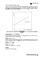
Denition of Tuning Sensitivity and Specifying Aperture
4Format5 . . . . . . . . . . . . . . . . . . . . . . . . .
4Format5 Menu . . . . . . . . . . . . . . . . . . . . .
POWER UNIT:dBm (POWUNIT DBM) . . . . . . . . . .
dBV (POWUNIT DBV) . . . . . . . . . . . . . . . . .
dBuV (POWUNIT DBUV) . . . . . . . . . . . . . . . .
Watt (POWUNIT W) . . . . . . . . . . . . . . . . .
Volt (POWUNIT V) . . . . . . . . . . . . . . . . .
4Display5 . . . . . . . . . . . . . . . . . . . . . . . . .
4Display5 Menu . . . . . . . . . . . . . . . . . . . . .
AUTO SCALE (AUTO) . . . . . . . . . . . . . . . . .
SCALE REFERENCE . . . . . . . . . . . . . . . . .
DEF TRACE[DATA] . . . . . . . . . . . . . . . . .
DATA HOLD [ ] (DHOLD OFF|MAX|MIN) . . . . . . . .
DATA MATH [ ] (MATH DATA|DPLM|DMNM|DDVM) . . .
MORE . . . . . . . . . . . . . . . . . . . . . . . .
Scale Menu . . . . . . . . . . . . . . . . . . . . . .
AUTO SCALE . . . . . . . . . . . . . . . . . . . .
SCALE/DIV (SCAL <Value>) . . . . . . . . . . . . .
REFERENCE POSITION (REFP <Value>) . . . . . . . .
REFERENCE VALUE (REFV <Value>) . . . . . . . . .
MKR!REFERENCE (MKRREF) . . . . . . . . . . . . .
SCALE FOR [DATA] (SCAF DATA|MEMO) . . . . . . . .
D&M SCALE [COUPLE] (SCAC OFF|0|ON|1) . . . . . .
RETURN . . . . . . . . . . . . . . . . . . . . . . .
Dene Trace Menu . . . . . . . . . . . . . . . . . . .
DISPLAY: DATA (DISP DATA) . . . . . . . . . . . .
NNNNNNNNNNNNNNNNNNNNNNNNNNNNNNNNNNN
NNNNNNNNNNNNNNNNNNNNNNNNNNNNNNNNNNNNNNNNNNNN
NNNNNNNNNNNNNNNNN
NNNNNNNNNNNNNNNNNNNNNNNNNNNNNNNNNNN
NNNNNNNNNNNNNNNNNNNNNNNNNNNNNNNNNNNNNNNNNNNNNNN
NNNNNNNNNNNNNNNNNNNNNNNNNNNNNNNNNNNNNNNNNNNNNNNNNNNNNNNN
NNNNNNNNNNNNNNNNNNNNNNNNNNNNNNNNNNNNNNNNNNNNNNNNNNNNN
NNNNNNNNNNNNNNNNNNNNNNNNNNNNNNNNNNNNNNNNNNNNNNNNNN
NNNNNNNNNNNNNNNNNNNNNNNNNNNNNNNNNNNNNNNNNNNNNNNNNN
NNNNNNNNNNNNNNNNNNNNNNNNNN
NNNNNNNNNNNNNNNNNNNN
NNNNNNNNNNNNNNNNNNNNNNNNNN
NNNNNNNNNNNNNNNNNNNNNNNNNNNNNNNNNNNNNNNNNNNNNNNNNNNNNNNNNNN
NNNNNNNNNNNNNNNNNNNNNNNNNNNNNNNNNNNNNNNNN
NNNNNNNNNNNNNNNNNNNNNNNNNNNNNNNNNNNNNNNNNNNN
NNNNNNNNNNN
NNNNNNNNNNNNNN
NNNNNNNNNNNNNN
NNNNNNNNNNNNNN
NNNNNNNNNNNNNNNNNNNNNNNNNNNNNNNN
NNNNNNNNNNNNNNNNNNNNNNNNNNNNNNNNNNNNNNNNNNNNNNN
NNNNNNNNNNNNNNNNNNNNNNNNNNNNNNNNNNNNNNNNNNNNNNN
NNNNNNNNNNNNNNNNNNNNNNNNNNNNNNNNNNNNNNNNN
NNNNNNNNNNNNNNNNNNNNNNNNNNNNNNNNNNNNNNNNNNNN
NNNNNNNNNNNNNN
NNNNNNNNNNNNNNNNNNNNNNNNNNNNNNNN
NNNNNNNNNNNNNNNNNNNNNNNNNNNNN
NNNNNNNNNNNNNNNNNNNNNNNNNNNNNNNNNNNNNNNNNNNNNNNNNNNNNNNN
NNNNNNNNNNNNNNNNNNNNNNNNNNNNNNNNNNNNNNNNNNNNNNN
NNNNNNNNNNNNNNNNNNNNNNNNNNNNNNNNNNNNNNNNNNN
NNNNNNNNNNNNNNNNNNNNNNNNNNNNNNNNNNNNNNNNNNNNNNNNNN
NNNNNNNNNNNNNNNNNNNNNNNNNNNNNNNNNNNNNNNNNNNNNNNNNNNNNNNN
NNNNNNNNNNNNNNNNNNNN
NNNNNNNNNNNNNNNNNNNNNNNNNNNNNNNNNNNNNNNNN
Contents-8
.
.
.
.
.
.
.
.
.
.
.
.
.
.
.
.
.
.
.
.
.
.
.
.
.
.
.
.
.
.
.
.
.
.
.
.
.
.
.
.
.
.
.
.
.
.
.
.
.
.
.
.
.
.
.
.
.
.
.
.
.
.
.
.
.
.
.
.
.
.
.
.
.
.
.
.
.
.
.
.
.
.
.
.
.
.
.
.
.
.
.
.
.
.
.
.
.
.
.
.
.
.
.
.
.
.
.
.
.
.
.
.
.
.
.
.
.
.
.
.
.
.
.
.
.
.
.
.
.
.
.
.
.
.
.
.
.
.
.
.
.
.
.
.
.
.
.
.
.
.
.
.
.
.
.
.
.
.
.
.
.
.
.
.
.
.
.
.
.
.
.
.
.
.
.
.
.
.
.
.
.
.
.
.
.
.
.
.
.
.
.
.
.
.
.
.
.
.
.
.
.
.
.
.
.
.
.
.
.
.
.
.
.
.
.
.
.
.
.
.
.
.
.
.
.
.
.
.
.
.
.
.
.
.
.
.
.
.
.
.
.
.
.
.
.
.
.
.
.
.
.
.
.
.
.
.
.
.
.
.
.
.
.
.
.
.
.
.
.
.
.
.
.
.
.
.
.
.
.
.
.
.
.
.
.
.
.
.
.
.
.
.
.
.
.
.
.
.
.
.
.
.
.
.
.
.
.
.
.
.
.
.
.
.
.
.
.
.
.
.
.
.
.
.
.
.
.
.
.
.
.
.
.
.
.
.
.
.
.
.
.
.
.
.
.
.
.
.
.
.
.
.
.
.
.
.
.
.
.
.
.
.
.
.
.
.
.
.
.
.
.
.
.
.
.
.
.
.
.
.
.
.
.
.
.
.
.
.
.
.
.
.
.
.
.
.
.
.
.
.
.
.
.
.
.
.
.
.
.
.
.
.
.
.
.
.
.
.
.
.
.
.
.
.
.
.
.
.
.
.
.
.
.
.
.
.
.
.
.
.
.
.
.
.
8-6
8-7
8-7
8-7
8-8
8-8
8-9
8-9
8-9
8-9
8-9
8-9
8-10
8-10
8-10
8-10
8-10
8-12
8-12
8-12
8-12
8-12
8-12
8-12
8-13
8-15
8-15
8-15
8-15
8-15
8-15
8-16
8-16
8-16
8-16
8-16
8-16
8-16
8-16
8-16
8-16
8-17
8-17
MEMORY (DISP MEMO) . . . . .
DATA and MEMORY (DISP DATM)
DATA!MEMORY (DATMEM) . . .
DATA!LIMIT MENU . . . . . .
RETURN . . . . . . . . . . . .
.
.
.
.
.
Data!Limit Menu . . . . . . . . .
.
.
.
.
.
.
.
.
.
.
.
.
.
.
.
.
.
.
.
.
.
.
.
.
.
.
.
.
.
.
.
.
.
.
.
.
Display MORE Menu . . . . . . . . . . . .
ALLOCAT'N:ALL INSTR (DISA ALLI) . . .
HALF INSTR HALF BASIC (DISA HIHB) . .
ALL BASIC (DISA ALLB) . . . . . . . .
BASIC STATUS (DISA BASS) . . . . . . .
TITLE (TITL <Character String>) . . .
ADJUST DISPLAY . . . . . . . . . . . .
RETURN . . . . . . . . . . . . . . . . .
Character Input Menu . . . . . . . . . . .
SELECT LETTER . . . . . . . . . . . . .
SPACE . . . . . . . . . . . . . . . . .
BACK SPACE . . . . . . . . . . . . . .
ERASE TITLE . . . . . . . . . . . . . .
DONE . . . . . . . . . . . . . . . . . .
CANCEL . . . . . . . . . . . . . . . . .
Display Adjustment Menu . . . . . . . . .
INTENSITY (INTE <Value>) . . . . . . .
.
.
.
.
.
.
.
.
.
.
.
.
.
.
.
.
.
.
.
.
.
.
.
.
.
.
.
.
.
.
.
.
.
.
.
.
.
.
.
.
.
.
.
.
.
.
.
.
.
.
.
.
.
.
.
.
.
.
.
.
.
.
NNNNNNNNNNNNNNNNNNNN
NNNNNNNNNNNNNNNNNNNNNNNNNNNNNNNNNNNNNNNNNNNNNNN
NNNNNNNNNNNNNNNNNNNNNNNNNNNNNNNNNNNNN
NNNNNNNNNNNNNNNNNNNNNNNNNNNNNNNNNNNNNNNNNNNNNNNNN
NNNNNNNNNNNNNNNNNNNN
NNNNNNNNNNNNNNNNNNNNNNNNNNNNNNNNNNNNNNNNNNNNNNNNNNNNN
LIMIT LINE on OFF (LIMILINE OFF|0|ON|1)
DATA!UPPER (DATLIMU) . . . . . . . . . .
DATA!LOWER (DATLIML) . . . . . . . . . .
DATA$UPPER (EXDATLIMU) . . . . . . . . .
DATA$LOWER (EXDATLIML) . . . . . . . . .
NNNNNNNNNNNNNNNNNNNNNNNNNNNNNNNNNN
NNNNNNNNNNNNNNNNNNNNNNNNNNNNNNNNNN
NNNNNNNNNNNNNNNNNNNNNNNNNNNNNNNNNN
NNNNNNNNNNNNNNNNNNNNNNNNNNNNNNNNNN
NNNNNNNNNNNNNNNNNNNNNNNNNNNNNNNNNNNNNNNNNNNNNNNNNNNNNNNNNNN
NNNNNNNNNNNNNNNNNNNNNNNNNNNNNNNNNNNNNNNNNNNNNNNNNNNNNNNNNNNNNNNNN
NNNNNNNNNNNNNNNNNNNNNNNNNNNNN
NNNNNNNNNNNNNNNNNNNNNNNNNNNNNNNNNNNNNN
NNNNNNNNNNNNNNNNN
NNNNNNNNNNNNNNNNNNNNNNNNNNNNNNNNNNNNNNNNNNNN
NNNNNNNNNNNNNNNNNNNN
NNNNNNNNNNNNNNNNNNNNNNNNNNNNNNNNNNNNNNNNN
NNNNNNNNNNNNNNNNN
NNNNNNNNNNNNNNNNNNNNNNNNNNNNNNNN
NNNNNNNNNNNNNNNNNNNNNNNNNNNNNNNNNNN
NNNNNNNNNNNNNN
NNNNNNNNNNNNNNNNNNNN
NNNNNNNNNNNNNNNNNNNNNNNNNNNNN
NNNNNNNNNNNNNNNNNNNNNNNNNNNNNNNNNNNNNNNNNNNNNNNNNNNNNNNNNNNNNN
BACKGROUND INTENSITY (BACI <Value>)
MODIFY COLORS . . . . . . . . . . . . .
DEFAULT COLORS (DEFC) . . . . . . . .
SAVE COLORS (SVCO) . . . . . . . . . .
RECALL COLORS (RECC) . . . . . . . . .
RETURN . . . . . . . . . . . . . . . . .
NNNNNNNNNNNNNNNNNNNNNNNNNNNNNNNNNNNNNNNNN
NNNNNNNNNNNNNNNNNNNNNNNNNNNNNNNNNNNNNNNNNNNN
NNNNNNNNNNNNNNNNNNNNNNNNNNNNNNNNNNN
NNNNNNNNNNNNNNNNNNNNNNNNNNNNNNNNNNNNNNNNN
NNNNNNNNNNNNNNNNNNNN
First Color Adjustment Menu . . . . . . . .
DATA (COLO DATA) . . . . . . . . . . .
MEMORY (COLO MEM) . . . . . . . . . . .
LIMIT LINE PARAMETER (COLO PARAM) . .
GRATICULE (COLO GRAT) . . . . . . . .
WARNING (COLO WARN) . . . . . . . . . .
TEXT MARKER (COLO TEXT) . . . . . . .
MORE . . . . . . . . . . . . . . . . . .
NNNNNNNNNNNNNN
NNNNNNNNNNNNNNNNNNNN
NNNNNNNNNNNNNNNNNNNNNNNNNNNNNNNNNNNNNNNNNNNNNNNNNNNNNNNNNNNNNN
NNNNNNNNNNNNNNNNNNNNNNNNNNNNN
NNNNNNNNNNNNNNNNNNNNNNN
NNNNNNNNNNNNNNNNNNNNNNNNNNNNNNNNNNN
NNNNNNNNNNNNNN
.
.
.
.
.
.
.
.
.
.
.
.
.
.
.
.
.
.
.
.
.
.
.
.
.
.
.
.
.
.
.
.
.
.
.
.
.
.
.
.
.
.
.
.
.
.
.
.
.
.
.
.
.
.
.
.
.
.
.
.
.
.
.
.
.
.
.
.
.
.
.
.
.
.
.
.
.
.
.
.
.
.
.
.
.
.
.
.
.
.
.
.
.
.
.
.
.
.
.
.
.
.
.
.
.
.
.
.
.
.
.
.
.
.
.
.
.
.
.
.
.
.
.
.
.
.
.
.
.
.
.
.
.
.
.
.
.
.
.
.
.
.
.
.
.
.
.
.
.
.
.
.
.
.
.
.
.
.
.
.
.
.
.
.
.
.
.
.
.
.
.
.
.
.
.
.
.
.
.
.
.
.
.
.
.
.
.
.
.
.
.
.
.
.
.
.
.
.
.
.
.
.
.
.
.
.
.
.
.
.
.
.
.
.
.
.
.
.
.
.
.
.
.
.
.
.
.
.
.
.
.
.
.
.
.
.
.
.
.
.
.
.
.
.
.
.
.
.
.
.
.
.
.
.
.
.
.
.
.
.
.
.
.
.
.
.
.
.
.
.
.
.
.
.
.
.
.
.
.
.
.
.
.
.
.
.
.
.
.
.
.
.
.
.
.
.
.
.
.
.
.
.
.
.
.
.
.
.
.
.
.
.
.
.
.
.
.
.
.
.
.
.
.
.
.
.
.
.
.
.
.
.
.
.
.
.
.
.
.
.
.
.
.
.
.
.
.
.
.
.
.
.
.
.
.
.
.
.
.
.
.
.
.
.
.
.
.
.
.
.
.
.
.
.
.
.
.
.
.
.
.
.
.
.
.
.
.
.
.
.
.
.
.
.
.
.
.
.
.
.
.
.
.
.
.
.
.
.
.
.
.
.
.
.
.
.
.
.
.
.
.
.
.
.
.
.
.
.
.
.
.
.
.
.
.
.
.
.
.
.
.
.
.
.
.
.
.
.
.
.
.
.
.
.
.
.
.
.
.
.
.
.
.
.
.
.
.
.
.
.
.
.
.
.
.
.
.
.
.
.
.
.
.
.
.
.
.
.
.
.
.
.
.
.
.
.
.
.
.
.
.
.
.
.
.
.
.
.
.
.
.
.
.
.
.
.
.
.
.
.
.
.
.
.
.
.
.
.
.
.
.
.
.
.
.
.
.
.
.
.
.
.
.
.
.
.
.
.
.
.
.
.
.
.
.
.
.
.
.
.
.
.
.
.
.
.
.
.
.
.
.
.
.
.
.
.
.
.
.
.
.
.
.
.
.
.
.
.
8-17
8-17
8-17
8-17
8-17
8-17
8-17
8-17
8-17
8-17
8-17
8-18
8-18
8-18
8-18
8-18
8-18
8-18
8-18
8-18
8-18
8-18
8-18
8-18
8-18
8-19
8-19
8-19
8-19
8-19
8-19
8-19
8-19
8-19
8-19
8-19
8-19
8-19
8-19
8-20
8-20
8-20
Contents-9
RETURN . . . . . . . . . . . . .
Second Color Adjustment Menu . . .
TINT (TINT <Value>) . . . . . .
BRIGHTNESS (CBRI <Value>) . .
COLOR (COLOR <Value>) . . . . .
RESET COLOR (RSCO) . . . . . .
RETURN . . . . . . . . . . . . .
Change Pen Color Menu . . . . . .
IBASIC (COLO IBT) . . . . . . .
PEN1 (COLO PEN1) . . . . . . .
PEN2 (COLO PEN2) . . . . . . .
PEN3 (COLO PEN3) . . . . . . .
PEN4 (COLO PEN4) . . . . . . .
PEN5 (COLO PEN5) . . . . . . .
PEN6 (COLO PEN6) . . . . . . .
RETURN . . . . . . . . . . . . .
4Menu5 . . . . . . . . . . . . . . . .
4Menu5 Menu . . . . . . . . . . . .
SWEEP . . . . . . . . . . . . .
NNNNNNNNNNNNNNNNNNNN
NNNNNNNNNNNNNN
NNNNNNNNNNNNNNNNNNNNNNNNNNNNNNNN
NNNNNNNNNNNNNNNNN
NNNNNNNNNNNNNNNNNNNNNNNNNNNNNNNNNNN
NNNNNNNNNNNNNNNNNNNN
NNNNNNNNNNNNNNNNNNNN
NNNNNNNNNNNNNN
NNNNNNNNNNNNNN
NNNNNNNNNNNNNN
NNNNNNNNNNNNNN
NNNNNNNNNNNNNN
NNNNNNNNNNNNNN
NNNNNNNNNNNNNNNNNNNN
NNNNNNNNNNNNNNNNN
NNNNNNNNNNNNNNNNNNNNNNNNNNNNNNNNNNNNNNNNNNNNNNNNNNNNNNNN
SWEEP TYPE [
]
AUTO FREQ CONTROL
MARKER . . . . . . .
MKR SEARCH . . . .
DETECTION [SAMPLE]
CARRIER MENU . . .
CABLE LOSS COMPEN
NNNNNNNNNNNNNNNNNNNNNNNNNNNNNNNNNNNNNNNNNNNNNNNNNNNNN
NNNNNNNNNNNNNNNNNNNN
NNNNNNNNNNNNNNNNNNNNNNNNNNNNNNNN
NNNNNNNNNNNNNNNNNNNNNNNNNNNNNNNNNNNNNNNNNNNNNNNNNNNNNNNN
NNNNNNNNNNNNNNNNNNNNNNNNNNNNNNNNNNNNNNNNNNNNNNNNNNNNN
NNNNNNNNNNNNNNNNN
NNNNNNNNNNNNNN
NNNNNNNNNNNNNNNNNNNN
NNNNNNNNNNNNNN
NNNNNNNNNNNNNNNNNNNNNNNNNNNNNNNNNNNNNNNNNNNNNNNNNN
.
.
.
.
.
.
.
.
.
.
.
.
.
.
.
.
.
.
.
.
.
NNNNNNNNNNNNNNNNNNNNNNNNNNNNNNNNNNNNN
NNNNNNNNNNNNNNNNNNNN
Marker! Menu . . . . . . . . . .
MKR!START (MKRSTAR) . . . . .
MKR!STOP (MKRSTOP) . . . . . .
MKR!CENTER (MKRCENT) . . . .
RETURN . . . . . . . . . . . . .
Automatic Frequency Control Menu .
AFC on OFF (AFC OFF|0|ON|1) .
TARGET (AFCTARG <Value>) . . .
NNNNNNNNNNNNNNNNNNNNNNNNNNNNNNNNNN
NNNNNNNNNNNNNNNNNNNN
NNNNNNNNNNNNNNNNNNNNNNNNNNNNNNNN
NNNNNNNNNNNNNNNNNNNN
Contents-10
.
.
.
.
.
.
.
.
.
.
.
.
.
.
.
.
.
.
.
(DET POS|NEG|SAM)
NUMBER of POINTS (POIN <Value>)
SWEEP TIME (SWET <Value>) . . .
MARKER!MENU . . . . . . . . . .
RETURN . . . . . . . . . . . . . .
NNNNNNNNNNNNNNNNNNNNNNNNNNNN
.
.
.
.
.
.
.
.
.
.
.
.
.
.
.
.
.
.
.
. . . . . . . . . .
. . . . . . . . . .
. . . . . . . . . .
NNNNNNNNNNNNNNNNNNNNNNNNNNNNNNNN
NNNNNNNNNNNNNNNNNNNNNNNNNNNNNNN
.
.
.
.
.
.
.
.
.
.
.
.
.
.
.
.
.
.
.
(SWPT LOGF|LINF)
. . . .
. . . .
Sweep Menu . . . . . . . . .
START (STAR <Value>) . . .
STOP (STOP <Value>) . . . .
CENTER (CENT <Value>) . . .
SPAN (SPAN <Value>) . . . .
NNNNNNNNNNNNNNNNNNNNNNNNNNNNNNNNNNNNNN
.
.
.
.
.
.
.
.
.
.
.
.
.
.
.
.
.
.
.
.
.
.
.
.
.
.
.
.
.
.
.
.
.
.
.
.
.
.
.
.
.
.
.
.
.
.
.
.
.
.
.
.
.
.
.
.
.
.
.
.
.
.
.
.
.
.
.
.
.
.
.
.
.
.
.
.
.
.
.
.
.
.
.
.
.
.
.
.
.
.
.
.
.
.
.
.
.
.
.
.
.
.
.
.
.
.
.
.
.
.
.
.
.
.
.
.
.
.
.
.
.
.
.
.
.
.
.
.
.
.
.
.
.
.
.
.
.
.
.
.
.
.
.
.
.
.
.
.
.
.
.
.
.
.
.
.
.
.
.
.
.
.
.
.
.
.
.
.
.
.
.
.
.
.
.
.
.
.
.
.
.
.
.
.
.
.
.
.
.
.
.
.
.
.
.
.
.
.
.
.
.
.
.
.
.
.
.
.
.
.
.
.
.
.
.
.
.
.
.
.
.
.
.
.
.
.
.
.
.
.
.
.
.
.
.
.
.
.
.
.
.
.
.
.
.
.
.
.
.
.
.
.
.
.
.
.
.
.
.
.
.
.
.
.
.
.
.
.
.
.
.
.
.
.
.
.
.
.
.
.
.
.
.
.
.
.
.
.
.
.
.
.
.
.
.
.
.
.
.
.
.
.
.
.
.
.
.
.
.
.
.
.
.
.
.
.
.
.
.
.
.
.
.
.
.
.
.
.
.
.
.
.
.
.
.
.
.
.
.
.
.
.
.
.
.
.
.
.
.
.
.
.
.
.
.
.
.
.
.
.
.
.
.
.
.
.
.
.
.
.
.
.
.
.
.
.
.
.
.
.
.
.
.
.
.
.
.
.
.
.
.
.
.
.
.
.
.
.
.
.
.
.
.
.
.
.
.
.
.
.
.
.
.
.
.
.
.
.
.
.
.
.
.
.
.
.
.
.
.
.
.
.
.
.
.
.
.
.
.
.
.
.
.
.
.
.
.
.
.
.
.
.
.
.
.
.
.
.
.
.
.
.
.
.
.
.
.
.
.
.
.
.
.
.
.
.
.
.
.
.
.
.
.
.
.
.
.
.
.
.
.
.
.
.
.
.
.
.
.
.
.
.
.
.
.
.
.
.
.
.
.
.
.
.
.
.
.
.
.
.
.
.
.
.
.
.
.
.
.
.
.
.
.
.
.
.
.
.
.
.
.
.
.
.
.
.
.
.
.
.
.
.
.
.
.
.
.
.
.
.
.
.
.
.
.
.
.
.
.
.
.
.
.
.
.
.
.
.
.
.
.
.
.
.
.
.
.
.
.
.
.
.
.
.
.
.
.
.
.
.
.
.
.
.
.
.
.
.
.
.
.
.
.
.
.
.
.
.
.
.
.
.
.
.
.
.
.
.
.
.
.
.
.
.
.
.
.
.
.
.
.
.
.
.
.
.
.
.
.
.
.
.
.
.
.
.
.
.
.
.
.
.
.
.
.
.
.
.
.
.
.
.
.
.
.
.
.
.
.
.
.
.
.
.
.
.
.
.
.
.
.
.
.
.
.
.
.
.
.
.
.
.
.
.
.
.
.
.
.
.
.
.
.
.
.
.
.
.
.
.
.
.
.
.
.
.
.
.
.
.
.
.
.
.
.
.
.
.
.
.
.
.
.
.
.
.
.
.
.
.
.
.
.
.
.
.
.
.
.
.
.
.
.
.
.
.
.
.
.
.
.
.
8-20
8-20
8-20
8-20
8-20
8-20
8-20
8-20
8-20
8-20
8-20
8-21
8-21
8-21
8-21
8-21
8-22
8-22
8-22
8-22
8-22
8-23
8-23
8-23
8-23
8-23
8-23
8-23
8-23
8-23
8-23
8-24
8-24
8-24
8-24
8-24
8-24
8-24
8-24
8-24
8-24
8-25
8-25
TOLERANCE (AFCTOL <Value>) . . . . . .
SENSITIVTY (AFCSENS <Value>) . . . .
AFC MAX CTRL VOLT (AFCMAXV <Value>)
AFC MIN CTRL VOLT (AFCMINV <Value>)
MAX ITERATION (AFCITER <Value>) . . .
RETURN . . . . . . . . . . . . . . . . .
.
.
.
.
.
.
Marker Menu . . . . . . . . . . . . . . . .
SUB MKR . . . . . . . . . . . . . . . . .
1MKR MENU . . . . . . . . . . . . . . . .
NNNNNNNNNNNNNNNNNNNNNNNNNNNNN
NNNNNNNNNNNNNNNNNNNNNNNNNNNNNNNN
NNNNNNNNNNNNNNNNNNNNNNNNNNNNNNNNNNNNNNNNNNNNNNNNNNNNN
NNNNNNNNNNNNNNNNNNNNNNNNNNNNNNNNNNNNNNNNNNNNNNNNNNNNN
NNNNNNNNNNNNNNNNNNNNNNNNNNNNNNNNNNNNNNNNN
NNNNNNNNNNNNNNNNNNNN
NNNNNNNNNNNNNNNNNNNNNNN
NNNNNNNNNNNNNNNNNNNNNNNNNNNNN
NNNNNNNNNNNNNNNNNNNNNNNNNNNNNNNNNNNNNNNNNNNNNNNNNNNNN
.
.
.
.
.
.
.
.
.
.
.
.
.
.
.
.
.
.
.
.
.
.
.
.
.
.
.
.
.
.
.
.
.
.
.
.
.
.
.
.
.
.
.
.
.
.
.
.
.
.
.
.
.
.
.
.
.
.
.
.
.
.
.
.
.
.
.
.
.
.
.
.
INTG NOISE on OFF (MEAINOIS OFF|0|ON|1) (INTGNOIS?)
PRESET MKRS (PRSMKRS) . . . . . . . . . . . . . . . . .
MKR ON [ ] (MKRO DATA|MEMO) . . . . . . . . . . . . . .
MKR [CONT] (MKRCONT OFF|0|ON|1) . . . . . . . . . . . .
MKR LIST on OFF (MKRL OFF|0|ON|1) . . . . . . . . . . .
RETURN . . . . . . . . . . . . . . . . . . . . . . . . . .
NNNNNNNNNNNNNNNNNNNNNNNNNNNNNNNNNNN
NNNNNNNNNNNNNNNNNNNNNNNNNNNNNNNN
NNNNNNNNNNNNNNNNNNNNNNNNNNNNNNNN
NNNNNNNNNNNNNNNNNNNNNNNNNNNNNNNNNNNNNNNNNNNNNNN
NNNNNNNNNNNNNNNNNNNN
Sub-marker Menu . . . . . . . . . .
SUB MKR 1 (SMKR1 OFF|0|ON|1) .
2 (SMKR2 OFF|0|ON|1) . . . . . .
3 (SMKR3 OFF|0|ON|1) . . . . . .
4 (SMKR4 OFF|0|ON|1) . . . . . .
CLEAR SUB MKRS (CLRSMKRS) . . .
RETURN . . . . . . . . . . . . . .
1 Marker Menu . . . . . . . . . . .
1MKR (DMKR ON) . . . . . . . . . .
FIXED 1MKR (DMKR FIX) . . . . .
TRACKING 1MKR (DMKR TRAC) . . .
1MODE OFF (DMKR OFF) . . . . . .
.
.
.
.
.
.
.
.
.
.
.
.
.
.
.
.
.
.
.
.
.
.
.
.
1MKR SWP PARAM (DMKRPRM <Value>) .
FIXED1MKR VALUE (DMKRVAL <Value>) .
RETURN . . . . . . . . . . . . . . . .
Marker Search Menu . . . . . . . . . . .
SEARCH: PEAK (SEAM PEAK) . . . . . .
MAX (SEAM MAX) . . . . . . . . . . . .
MIN (SEAM MIN) . . . . . . . . . . . .
TARGET (SEAM TARG) . . . . . . . . .
NNNNNNNNNNNNNNNNNNNNNNNNNNNNN
NNNNN
NNNNN
NNNNN
NNNNNNNNNNNNNNNNNNNNNNNNNNNNNNNNNNNNNNNNNNNN
NNNNNNNNNNNNNNNNNNNN
NNNNNNNNNNNNNN
NNNNNNNNNNNNNNNNNNNNNNNNNNNNNNNN
NNNNNNNNNNNNNNNNNNNNNNNNNNNNNNNNNNNNNNNNN
NNNNNNNNNNNNNNNNNNNNNNNNNNNNN
NNNNNNNNNNNNNNNNNNNNNNNNNNNNNNNNNNNNNNNNNNNN
NNNNNNNNNNNNNNNNNNNNNNNNNNNNNNNNNNNNNNNNNNNNNNN
NNNNNNNNNNNNNNNNNNNN
NNNNNNNNNNNNNNNNNNNNNNNNNNNNNNNNNNNNNN
NNNNNNNNNNN
NNNNNNNNNNN
NNNNNNNNNNNNNNNNNNNN
NNNNNNNNNNNNNNNNNNNNNNNNNNNNNNNNNNNNNNNNNNNNNNNNNNNNN
SRCH TRACK on
SEARCH RANGE
SUB MKR . . .
RETURN . . . .
OFF (TRACK OFF|0|ON|1)
.
.
.
Peak Menu . . . .
.
.
.
.
PEAK (SEAM PEAK) .
.
.
.
.
.
NEXT PEAK (SEANPK) .
.
.
.
.
.
.
NEXT PEAK LEFT (SEANPKL) .
NNNNNNNNNNNNNNNNNNNNNNNNNNNNNNNNNNNNNN
.
.
.
.
.
.
.
.
.
.
.
.
.
.
.
.
.
.
.
.
NNNNNNNNNNNNNNNNNNNNNNN
NNNNNNNNNNNNNNNNNNNN
NNNNNNNNNNNNNN
NNNNNNNNNNNNNNNNNNNNNNNNNNNNN
NNNNNNNNNNNNNNNNNNNNNNNNNNNNNNNNNNNNNNNNNNNN
.
.
.
.
.
.
.
.
.
.
.
.
.
.
.
.
.
.
.
.
.
.
.
.
.
.
.
.
.
.
.
.
.
.
.
.
.
.
.
.
.
.
.
.
.
.
.
.
.
.
.
.
.
.
.
.
.
.
.
.
.
.
.
.
.
.
.
.
.
.
.
.
.
.
.
.
.
.
.
.
.
.
.
.
.
.
.
.
.
.
.
.
.
.
.
.
.
.
.
.
.
.
.
.
.
.
.
.
.
.
.
.
.
.
.
.
.
.
.
.
.
.
.
.
.
.
.
.
.
.
.
.
.
.
.
.
.
.
.
.
.
.
.
.
.
.
.
.
.
.
.
.
.
.
.
.
.
.
.
.
.
.
.
.
.
.
.
.
.
.
.
.
.
.
.
.
.
.
.
.
.
.
.
.
.
.
.
.
.
.
.
.
.
.
.
.
.
.
.
.
.
.
.
.
.
.
.
.
.
.
.
.
.
.
.
.
.
.
.
.
.
.
.
.
.
.
.
.
.
.
.
.
.
.
.
.
.
.
.
.
.
.
.
.
.
.
.
.
.
.
.
.
.
.
.
.
.
.
.
.
.
.
.
.
.
.
.
.
.
.
.
.
.
.
.
.
.
.
.
.
.
.
.
.
.
.
.
.
.
.
.
.
.
.
.
.
.
.
.
.
.
.
.
.
.
.
.
.
.
.
.
.
.
.
.
.
.
.
.
.
.
.
.
.
.
.
.
.
.
.
.
.
.
.
.
.
.
.
.
.
.
.
.
.
.
.
.
.
.
.
.
.
.
.
.
.
.
.
.
.
.
.
.
.
.
.
.
.
.
.
.
.
.
.
.
.
.
.
.
.
.
.
.
.
.
.
.
.
.
.
.
.
.
.
.
.
.
.
.
.
.
.
.
.
.
.
.
.
.
.
.
.
.
.
.
.
.
.
.
.
.
.
.
.
.
.
.
.
.
.
.
.
.
.
.
.
.
.
.
.
.
.
.
.
.
.
.
.
.
.
.
.
.
.
.
.
.
.
.
.
.
.
.
.
.
.
.
.
.
.
.
.
.
.
.
.
.
.
.
.
.
.
.
.
.
.
.
.
.
.
.
.
.
.
.
.
.
.
.
.
.
.
.
.
.
.
.
.
.
.
.
.
.
.
.
.
.
.
.
.
.
.
.
.
.
.
.
.
.
.
.
.
.
.
.
.
.
.
.
.
.
.
.
.
.
.
.
.
.
.
.
.
.
.
.
.
.
.
.
.
.
.
.
.
.
.
.
.
.
.
.
.
.
.
.
.
.
.
.
.
.
.
.
.
.
.
.
.
.
.
.
.
.
.
.
.
.
.
.
.
.
.
.
.
.
.
.
.
.
.
.
8-25
8-25
8-25
8-25
8-25
8-25
8-26
8-26
8-26
8-26
8-26
8-26
8-27
8-27
8-27
8-27
8-27
8-27
8-27
8-27
8-27
8-27
8-28
8-28
8-28
8-28
8-28
8-28
8-28
8-28
8-29
8-29
8-29
8-29
8-29
8-29
8-30
8-30
8-30
8-30
8-30
8-30
8-30
Contents-11
NNNNNNNNNNNNNNNNNNNNNNNNNNNNNNNNNNNNNNNNNNNNNNN
NEXT PEAK RIGHT
PEAK DEF MENU .
SUB MKR . . . .
RETURN . . . . .
(SEANPKR) . . . . . . . . . . . . . . . . . . . . . .
.
.
.
Target Menu . . . . .
.
.
.
.
.
.
.
.
.
.
.
.
.
.
.
.
.
.
.
.
.
.
.
.
.
.
.
.
.
.
.
.
.
.
.
.
.
.
.
.
.
.
.
.
.
.
.
.
.
.
.
.
.
.
.
.
.
.
.
.
.
.
.
.
.
.
.
.
.
.
.
.
.
.
.
.
.
.
.
.
.
.
.
.
.
.
.
.
.
.
.
.
.
.
.
.
.
.
.
.
.
.
.
.
.
.
.
.
.
.
.
.
.
.
.
.
.
.
.
.
.
.
.
.
.
.
.
9. Control Block
4Mod5 . . . . . . . . . . . . . . . . . . .
4Mod5 Menu . . . . . . . . . . . . . . .
MOD AMPLITUDE (MODAMP <Value>) . .
MOD OUT on OFF (MODO OFF|0|ON|1) .
4RF/LO5 . . . . . . . . . . . . . . . . . .
4RF/LO5 Menu . . . . . . . . . . . . . .
.
.
.
.
.
.
.
.
.
.
.
.
NNNNNNNNNNNNNNNNNNNNNNNNNNNNNNNNNNNNNNNNN
NNNNNNNNNNNNNNNNNNNNNNN
NNNNNNNNNNNNNNNNNNNN
NNNNNNNNNNNNNNNNNNNN
TARGET (SEATARG <Value>)
SEARCH LEFT (SEAL) . . .
SEARCH RIGHT (SEAR) . .
SUB MKR . . . . . . . . .
RETURN . . . . . . . . . .
NNNNNNNNNNNNNNNNNNNNNNNNNNNNNNNNNNN
NNNNNNNNNNNNNNNNNNNNNNNNNNNNNNNNNNNNNN
NNNNNNNNNNNNNNNNNNNNNNN
NNNNNNNNNNNNNNNNNNNN
Search Range Menu . . . . .
NNNNNNNNNNNNNNNNNNNNNNNNNNNNNNNNNNNNNNNNNNNNNNNNNN
PART SRCH on OFF (PARS OFF|0|ON|1)
MKR1!SEARCH RNG (SEARSTR) . . . . .
MKR!LEFT RNG (SEARSTRL) . . . . . .
MKR!RIGHT RNG (SEARSTRR) . . . . .
RETURN . . . . . . . . . . . . . . . .
NNNNNNNNNNNNNNNNNNNNNNNNNNNNNNNNNNNNNNNNNNNNNNNNN
NNNNNNNNNNNNNNNNNNNNNNNNNNNNNNNNNNNNNNNN
NNNNNNNNNNNNNNNNNNNNNNNNNNNNNNNNNNNNNNNNNNN
NNNNNNNNNNNNNNNNNNNN
Dene Peak Menu . . . . . . . . . . . .
NNNNNNNNNNNNNNNNNNNNNNNNNNNNNNNNNNNNNNNNNNNNNNNNNN
.
.
.
.
.
.
.
.
.
.
.
.
.
.
.
.
THRESHOLD on OFF (PKTHRE OFF|0|ON|1)
THRESHOLD VALUE (PKTHVAL <Value>) . .
MKR!THRESHOLD (MKRTHRE) . . . . . . .
PEAK DEF: 1Y (PKDLTY <Value>) . . . .
RETURN . . . . . . . . . . . . . . . . .
NNNNNNNNNNNNNNNNNNNNNNNNNNNNNNNNNNNNNNNNNNNNNNN
NNNNNNNNNNNNNNNNNNNNNNNNNNNNNNNNNNNNNNNNNNN
NNNNNNNNNNNNNNNNNNNNNNNNNNNNNNNNNNNNNN
NNNNNNNNNNNNNNNNNNNN
Carrier Menu . . . . . . . . . . . .
CARRIER!CENTER (CARRCENT) . . .
22CARR!CENTER (CARR2CENT) . .
32CARR!CENTER (CARR3CENT) . .
RETURN . . . . . . . . . . . . . .
Cable Loss Compensation Menu . . . .
NNNNNNNNNNNNNNNNNNNNNNNNNNNNNNNNNNNNNNNNNNNNNN
NNNNNNNNNNNNNNNNNNNNNNNNNNNNNNNNNNNNNNNNNNNN
NNNNNNNNNNNNNNNNNNNNNNNNNNNNNNNNNNNNNNNNNNNN
NNNNNNNNNNNNNNNNNNNN
NNNNNNNNNNNNNNNNNNNNNNNNNNNNNNNNNNNNNNNNN
.
.
.
.
.
.
COMPEN on OFF (LCOMP OFF|0|ON|1)
SLOPE (SLOPE <Value>) . . . . . . .
LOSS (LOSS <Value>) . . . . . . . .
RETURN . . . . . . . . . . . . . . .
NNNNNNNNNNNNNNNNN
NNNNNNNNNNNNNN
NNNNNNNNNNNNNNNNNNNN
NNNNNNNNNNNNNNNNNNNNNNNNNNNNNNNNNNNNNNNNN
NNNNNNNNNNNNNNNNNNNNNNNNNNNNNNNNNNNNNNNNNNNN
NNNNNNNNNNNNNNNNNNNNNNNNNNNNNNNNNNNNNNNNNNNNNNNNNNNNNNNNNNN
LO
LO
SG
SG
.
.
.
.
.
.
.
.
.
.
.
.
.
.
.
.
.
.
.
.
.
.
.
.
.
.
.
.
.
.
.
.
.
.
.
.
.
.
.
.
.
.
.
.
.
.
.
.
.
.
.
.
.
.
.
.
.
.
.
.
.
.
.
.
.
.
.
.
.
.
.
.
.
.
.
.
.
.
.
.
.
.
.
.
.
.
.
.
.
.
.
.
.
.
.
.
.
.
.
.
.
.
.
.
.
.
.
.
.
.
.
.
.
.
.
.
.
.
.
.
.
.
.
.
.
.
.
.
.
.
.
.
.
.
.
.
.
.
.
.
.
.
.
.
.
.
.
.
.
.
.
.
.
.
.
.
.
.
.
.
.
.
.
.
.
.
.
.
.
.
.
.
.
.
.
.
.
.
.
.
.
.
.
.
.
.
.
.
.
.
.
.
.
.
.
.
.
.
.
.
.
.
.
.
.
.
.
.
.
.
.
.
.
.
.
.
.
.
.
.
.
.
.
.
.
.
.
.
.
.
.
.
.
.
.
.
.
.
.
.
.
.
.
.
.
.
.
.
.
.
.
.
.
.
.
.
.
.
.
.
.
.
.
.
.
.
.
.
.
.
.
.
.
.
.
.
.
.
.
.
.
.
.
.
.
.
.
.
.
.
.
.
.
.
.
.
.
.
.
.
.
.
.
.
.
.
.
.
.
.
.
.
.
.
.
.
.
.
.
.
.
.
.
.
.
.
.
.
.
.
.
.
.
.
.
.
.
.
.
.
.
.
.
.
.
.
.
.
.
.
.
.
.
.
.
.
.
.
.
.
.
.
.
.
.
.
.
.
.
.
.
.
.
.
.
.
.
.
.
.
.
.
.
.
.
.
.
.
.
.
.
.
.
.
.
.
.
.
.
.
.
.
.
.
.
.
.
.
.
.
.
.
.
.
.
.
.
.
.
.
.
.
.
.
.
.
.
.
.
.
.
.
.
.
.
.
.
.
.
.
.
.
.
.
.
.
.
.
.
.
.
.
.
.
.
.
.
.
.
.
.
.
.
.
.
.
.
.
.
.
.
.
.
.
.
.
.
.
.
.
.
.
.
.
.
.
.
.
.
.
.
.
.
.
.
.
.
.
.
.
.
.
.
.
.
.
.
.
.
.
.
.
.
.
.
.
.
.
.
.
.
.
.
.
.
.
.
.
.
.
.
.
.
.
.
.
.
.
.
.
.
.
.
.
.
.
.
.
.
.
.
.
.
.
.
.
.
.
.
.
.
.
.
.
.
.
.
.
.
.
.
.
.
.
.
.
.
.
.
.
9-2
9-2
9-2
9-2
9-3
9-3
9-3
9-4
9-4
9-4
CONTROL auto MAN (LOAUTO OFF|0|ON|1)
SWTCH TIME (LOSWT <Value>) . . . . . .
TYPE (SGTYPE <Value>) . . . . . . . . .
MAX FREQ . . . . . . . . . . . . . . . .
NNNNNNNNNNNNNNNNNNNNNNNNNNNNNNNNNNNNNNNNN
NNNNNNNNNNNNNNNNNNNNNNN
NNNNNNNNNNNNNNNNNNNNNNNNNNNNNNNNNNN
Contents-12
.
.
.
.
.
.
.
.
.
.
.
.
.
.
.
.
.
.
.
.
.
.
.
.
.
.
.
.
.
.
.
8-30
8-30
8-30
8-30
8-30
8-30
8-30
8-31
8-31
8-31
8-31
8-31
8-31
8-31
8-31
8-31
8-31
8-31
8-31
8-31
8-31
8-32
8-32
8-32
8-32
8-32
8-32
8-33
8-33
8-33
8-33
8-33
. . . . .
. . . . . . .
. . . . . . .
. . . . . . .
. . . . . . .
. . . . . . .
. . . . . . .
. . . . . . .
. . . . . . .
. . . . . . .
. . . . . . .
. . . . . . .
. . . . . . .
. . . . . . .
. . . . . . .
TRIG PLRTY POS neg (TRGP POS|NEG) . . . . . . .
4DC Control5 . . . . . . . . . . . . . . . . . . . . . . .
4DC Control5 Menu . . . . . . . . . . . . . . . . . . .
CTRL VOLTAGE (VCTRL <Value>) . . . . . . . . .
MKR ! CTRL VOLT (MKRVCTRL) (Analyzer Mode) . .
MIN CTRL VOLTAGE (MINVCTRL <Value>) . . . . .
MAX CTRL VOLTAGE (MAXVCTRL <Value>) . . . . .
CTRL DELAY (CTRLDLY <Value>) . . . . . . . . .
CTRLV CAL (Option 001 only) . . . . . . . . . . .
OUTPUT on OFF (VOUT OFF|0|ON|1) . . . . . . . .
DC Control Voltage Calibration Menu (Option 001 only) .
EXECUTE CTRLV CAL (CTRLVCAL) . . . . . . . . .
CTRLV CORR on OFF (CTRLVCORR OFF|0|ON|1) . . .
RETURN . . . . . . . . . . . . . . . . . . . . . .
4DC Power5 . . . . . . . . . . . . . . . . . . . . . . .
4DC Power5 Menu . . . . . . . . . . . . . . . . . . .
POWER VOLTAGE (VPOW <Value>) . . . . . . . . .
OUTPUT on OFF (VOUT OFF|0|ON|1) . . . . . . . .
NNNNNNNNNNNNNNNNNNNNNNNNNNNNNNNNNNNNNNNNNNNNNNN
DOWNCONV ON off (DNCONV OFF|0|ON|1)
. . . . . . . . . . . .
4Trigger5 Menu
. . . . . . . .
TRIGGER:HOLD (HOLD) . .
SINGLE (SING) . . . . . .
CONTINUOUS (CONT) . . . .
TRIG SRC:[FREE RUN] . .
MEASURE RESTART (REST) .
RETURN . . . . . . . . . .
Trigger Source Menu . . . . .
.
.
.
.
.
.
.
.
.
.
.
.
.
.
.
.
.
.
. .
. .
. .
. .
. .
. .
. .
. .
. .
TRIGGER:FREE RUN (TRGS INT) . .
EXTERNAL (TRGS EXT) . . . . . . .
GPIB (TRGS BUS) . . . . . . . . .
MANUAL (TRGS MAN) . . . . . . . .
VALUE (TRGS VAL) (Analyzer Mode)
4Trigger5
NNNNNNNNNNNNNNNNNNNNNNNNNNNNNNNNNNNNNN
NNNNNNNNNNNNNNNNNNNN
NNNNNNNNNNNNNNNNNNNNNNNNNNNNNNNN
NNNNNNNNNNNNNNNNNNNNNNNNNNNNNNNNNNNNNNNNNNNNNNNNNNNNNNNNNNN
NNNNNNNNNNNNNNNNNNNNNNNNNNNNNNNNNNNNNNNNNNNNNNN
NNNNNNNNNNNNNNNNNNNN
NNNNNNNNNNNNNNNNNNNNNNNNNNNNNNNNNNNNNNNNNNNNNNNNNN
NNNNNNNNNNNNNNNNNNNNNNNNNN
NNNNNNNNNNNNNN
NNNNNNNNNNNNNNNNNNNN
NNNNNNNNNNNNNNNNN
NNNNNNNNNNNNNNNNNNNNNNNNNNNNNNNNNNNNNNNNNNNNNNNNNNNNNNNN
.
.
.
.
.
.
.
.
.
.
.
.
.
.
NNNNNNNNNNNNNNNNNNNNNNNNNNNNNNNNNNNNNN
NNNNNNNNNNNNNNNNNNNNNNNNNNNNNNNNNNNNNNNNNNNNNNNNN
NNNNNNNNNNNNNNNNNNNNNNNNNNNNNNNNNNNNNNNNNNNNNNNNNN
NNNNNNNNNNNNNNNNNNNNNNNNNNNNNNNNNNNNNNNNNNNNNNNNNN
NNNNNNNNNNNNNNNNNNNNNNNNNNNNNNNN
NNNNNNNNNNNNNNNNNNNNNNNNNNNNN
NNNNNNNNNNNNNNNNNNNNNNNNNNNNNNNNNNNNNNNNN
NNNNNNNNNNNNNNNNNNNNNNNNNNNNNNNNNNNNNNNNNNNNNNNNNNNNN
NNNNNNNNNNNNNNNNNNNNNNNNNNNNNNNNNNNNNNNNNNNNNNNNNNNNN
NNNNNNNNNNNNNNNNNNNN
NNNNNNNNNNNNNNNNNNNNNNNNNNNNNNNNNNNNNNNNN
NNNNNNNNNNNNNNNNNNNNNNNNNNNNNNNNNNNNNNNNN
10. Instrument State Block
4Copy5 . . . . . . . . . . . . . . . . .
Copy Menu . . . . . . . . . . . . .
PRINT [STANDARD] (PRINALL) . .
COPY ABORT (COPA) . . . . . . . .
.
.
.
.
COPY SKEY on OFF (PRSOFT ON|OFF) .
NNNNNNNNNNNNNNNNNNNNNNNNNNNNNNNNNNNNNNNNNNNNNNNNNN
NNNNNNNNNNNNNNNNNNNNNNNNNNNNNNNN
NNNNNNNNNNNNNNNNNNNNNNNNNNNNNNNNNNNNNNNNNNNNNNNNNN
NNNNNNNNNNNNNNNNNNNNNNNNNNNNNNNNNNNNNNNNNNNNNNNNNN
.
.
.
.
COPY TIME on OFF (COPT OFF|0|ON|1)
PRINT SETUP . . . . . . . . . . . . .
ORIENT [PORTRAIT] (LANDSCAPE) . . .
FORM FEED ON off (FORMFEED ON|OFF)
NNNNNNNNNNNNNNNNNNNNNNNNNNNNNNNNNNN
NNNNNNNNNNNNNNNNNNNNNNNNNNNNNNNNNNNNNNNNNNNNNNNNNNNNN
NNNNNNNNNNNNNNNNNNNNNNNNNNNNNNNNNNNNNNNNNNNNNNNNNN
.
.
.
.
.
.
.
.
.
.
.
.
.
.
.
.
.
.
.
.
.
.
.
.
.
.
.
.
.
.
.
.
.
.
.
.
.
.
.
.
.
.
.
.
.
.
.
.
.
.
.
.
.
.
.
.
.
.
.
.
.
.
.
.
.
.
.
.
.
.
.
.
.
.
.
.
.
.
.
.
.
.
.
.
.
.
.
.
.
.
.
.
.
.
.
.
.
.
.
.
.
.
.
.
.
.
.
.
.
.
.
.
.
.
.
.
.
.
.
.
.
.
.
.
.
.
.
.
.
.
.
.
.
.
.
.
.
.
.
.
.
.
.
.
.
.
.
.
.
.
.
.
.
.
.
.
.
.
.
.
.
.
.
.
.
.
.
.
.
.
.
.
.
.
.
.
.
.
.
.
.
.
.
.
.
.
.
.
.
.
.
.
.
.
.
.
.
.
.
.
.
.
.
.
.
.
.
.
.
.
.
.
.
.
.
.
.
.
.
.
.
.
.
.
.
.
.
.
.
.
.
.
.
.
.
.
.
.
.
.
.
.
.
.
.
.
.
.
.
.
.
.
.
.
.
.
.
.
.
.
.
.
.
.
.
.
.
.
.
.
.
.
.
.
.
.
.
.
.
.
.
.
.
.
.
.
.
.
.
.
.
.
.
.
.
.
.
.
.
.
.
.
.
.
.
.
.
.
.
.
.
.
.
.
.
.
.
.
.
.
.
.
.
.
.
.
.
.
.
.
.
.
.
.
.
.
.
.
.
.
.
.
.
.
.
.
.
.
.
.
.
.
.
.
.
.
.
.
.
.
.
.
.
.
.
.
.
.
.
.
.
.
.
.
.
.
.
.
.
.
.
.
.
.
.
.
.
.
.
.
.
.
.
.
.
.
.
.
.
.
.
.
.
.
.
.
.
.
.
.
.
.
.
.
.
.
.
9-5
9-6
9-6
9-6
9-6
9-6
9-6
9-6
9-7
9-7
9-7
9-7
9-7
9-7
9-7
9-7
9-8
9-8
9-8
9-8
9-8
9-9
9-9
9-9
9-9
9-9
9-9
9-9
9-9
9-10
9-10
9-10
9-10
.
.
.
.
.
.
.
.
.
.
.
.
.
.
.
.
.
.
.
.
.
.
.
.
.
.
.
.
.
.
.
.
.
.
.
.
.
.
.
.
.
.
.
.
.
.
.
.
.
.
.
.
.
.
.
.
.
.
.
.
.
.
.
.
.
.
.
.
.
.
.
.
.
.
.
.
.
.
.
.
.
.
.
.
.
.
.
.
.
.
.
.
.
.
.
.
.
.
.
10-2
10-2
10-2
10-2
10-2
10-3
10-3
10-3
10-3
Contents-13
OPERATING PARAMETERS (OPEP) .
Print Setup Menu . . . . . . . . .
PRINT:STANDARD (PRIS) . . . .
COLOR (PRIC) . . . . . . . . .
.
.
.
.
.
.
.
.
.
.
.
.
.
.
.
.
.
.
.
.
.
.
.
.
. . . .
. . . .
. . . .
. . . .
PRNT COLOR [FIXED] (PRICFIXE, PRICVARI) . . . .
DPI (DPI) . . . . . . . . . . . . . . . . . . . . .
TOP MARGIN (TMARG) . . . . . . . . . . . . . . . .
LFT MARGIN (LMARG) . . . . . . . . . . . . . . . .
DEFAULT SETUP (DFLT) . . . . . . . . . . . . . . .
RETURN . . . . . . . . . . . . . . . . . . . . . . .
Screen Menu . . . . . . . . . . . . . . . . . . . . .
PRINT [STANDARD] (PRINALL) . . . . . . . . . . .
COPY ABORT (COPA) . . . . . . . . . . . . . . . . .
COPY TIME on OFF (COPT OFF|0|ON|1) . . . . . . .
NEXT PAGE (NEXP) . . . . . . . . . . . . . . . . .
PREV PAGE (PREP) . . . . . . . . . . . . . . . . .
RESTORE DISPLAY (RESD) . . . . . . . . . . . . . .
4Save/Recall5 . . . . . . . . . . . . . . . . . . . . . . . .
4Save/Recall5 Menu . . . . . . . . . . . . . . . . . . . .
SAVE FILE . . . . . . . . . . . . . . . . . . . . .
RE-SAVE FILE (RESAVD <Character String>) . . . .
RECALL FILE . . . . . . . . . . . . . . . . . . . .
FILE UTILITIES . . . . . . . . . . . . . . . . . .
STOR DEV [ ] (STODDISK, STODMEMO) . . . . . . . .
Save File Menu . . . . . . . . . . . . . . . . . . . .
STATE (SAVDSTA <Character String>) . . . . . . .
DATA ONLY (SAVDDAT <Character String>) . . . . .
GRAPHICS (SAVDTIFF) . . . . . . . . . . . . . . .
4352A STATE (SAVDSTAC <string>) . . . . . . . . .
FILE UTILITIES . . . . . . . . . . . . . . . . . .
STOR DEV [ ] (STODDISK, STODMEMO) . . . . . . . .
Data Only Menu . . . . . . . . . . . . . . . . . . . .
SAVE BINARY (SAVDDAT <Character String>) . . . .
SAVE ASCII (SAVDASC) . . . . . . . . . . . . . . .
DEFINE SAVE DATA . . . . . . . . . . . . . . . . .
STOR DEV [ ] (STODDISK, STODMEMO) . . . . . . . .
Save Data Denition Menu . . . . . . . . . . . . . . .
DATA ON off (SAVDAT OFF|0|ON|1) . . . . . . . . .
MEM on OFF (SAVMEM OFF|0|ON|1) . . . . . . . . .
LIMIT on OFF (SAVLIM OFF|0|ON|1) (Analyzer Mode)
RETURN . . . . . . . . . . . . . . . . . . . . . . .
File Utilities Menu . . . . . . . . . . . . . . . . . . .
PURGE FILE (PURG <Character String>) . . . . . .
NNNNNNNNNNNNNNNNNNNNNNNNNNNNNNNNNNNNNNNNNNNNNNNNNNNNNNNNNNNNNN
NNNNNNNNNNNNNNNNNNNNNNNNNNNNNNNNNNNNNNNNNNNN
NNNNNNNNNNNNNNNNN
NNNNNNNNNNNNNNNNNNNNNNNNNNNNNNNNNNNNNNNNNNNNNNNNNNNNNNNN
NNNNNNNNNNN
NNNNNNNNNNNNNNNNNNNNNNNNNNNNNNNN
NNNNNNNNNNNNNNNNNNNNNNNNNNNNNNNN
NNNNNNNNNNNNNNNNNNNNNNNNNNNNNNNNNNNNNNNNN
NNNNNNNNNNNNNNNNNNNN
NNNNNNNNNNNNNNNNNNNNNNNNNNNNNNNNNNNNNNNNNNNNNNNNNN
NNNNNNNNNNNNNNNNNNNNNNNNNNNNNNNN
NNNNNNNNNNNNNNNNNNNNNNNNNNNNNNNNNNNNNNNNNNNNNNNNNN
NNNNNNNNNNNNNNNNNNNNNNNNNNNNN
NNNNNNNNNNNNNNNNNNNNNNNNNNNNN
NNNNNNNNNNNNNNNNNNNNNNNNNNNNNNNNNNNNNNNNNNNNNNN
NNNNNNNNNNNNNNNNNNNNNNNNNNNNN
NNNNNNNNNNNNNNNNNNNNNNNNNNNNNNNNNNNNNN
NNNNNNNNNNNNNNNNNNNNNNNNNNNNNNNNNNN
NNNNNNNNNNNNNNNNNNNNNNNNNNNNNNNNNNNNNNNNNNNN
NNNNNNNNNNNNNNNNNNNNNNNNNNNNNNNNNNNNNN
NNNNNNNNNNNNNNNNN
NNNNNNNNNNNNNNNNNNNNNNNNNNNNN
NNNNNNNNNNNNNNNNNNNNNNNNNN
NNNNNNNNNNNNNNNNNNNNNNNNNNNNNNNNNNN
NNNNNNNNNNNNNNNNNNNNNNNNNNNNNNNNNNNNNNNNNNNN
NNNNNNNNNNNNNNNNNNNNNNNNNNNNNNNNNNNNNN
NNNNNNNNNNNNNNNNNNNNNNNNNNNNNNNNNNN
NNNNNNNNNNNNNNNNNNNNNNNNNNNNNNNN
NNNNNNNNNNNNNNNNNNNNNNNNNNNNNNNNNNNNNNNNNNNNNNNNNN
NNNNNNNNNNNNNNNNNNNNNNNNNNNNNNNNNNNNNN
NNNNNNNNNNNNNNNNNNNNNNNNNNNNNNNNNNN
NNNNNNNNNNNNNNNNNNNNNNNNNNNNNNNN
NNNNNNNNNNNNNNNNNNNNNNNNNNNNNNNNNNNNNN
NNNNNNNNNNNNNNNNNNNN
NNNNNNNNNNNNNNNNNNNNNNNNNNNNNNNN
Contents-14
.
.
.
.
.
.
.
.
.
.
.
.
.
.
.
.
.
.
.
.
.
.
.
.
.
.
.
.
.
.
.
.
.
.
.
.
.
.
.
.
.
.
.
.
.
.
.
.
.
.
.
.
.
.
.
.
.
.
.
.
.
.
.
.
.
.
.
.
.
.
.
.
.
.
.
.
.
.
.
.
.
.
.
.
.
.
.
.
.
.
.
.
.
.
.
.
.
.
.
.
.
.
.
.
.
.
.
.
.
.
.
.
.
.
.
.
.
.
.
.
.
.
.
.
.
.
.
.
.
.
.
.
.
.
.
.
.
.
.
.
.
.
.
.
.
.
.
.
.
.
.
.
.
.
.
.
.
.
.
.
.
.
.
.
.
.
.
.
.
.
.
.
.
.
.
.
.
.
.
.
.
.
.
.
.
.
.
.
.
.
.
.
.
.
.
.
.
.
.
.
.
.
.
.
.
.
.
.
.
.
.
.
.
.
.
.
.
.
.
.
.
.
.
.
.
.
.
.
.
.
.
.
.
.
.
.
.
.
.
.
.
.
.
.
.
.
.
.
.
.
.
.
.
.
.
.
.
.
.
.
.
.
.
.
.
.
.
.
.
.
.
.
.
.
.
.
.
.
.
.
.
.
.
.
.
.
.
.
.
.
.
.
.
.
.
.
.
.
.
.
.
.
.
.
.
.
.
.
.
.
.
.
.
.
.
.
.
.
.
.
.
.
.
.
.
.
.
.
.
.
.
.
.
.
.
.
.
.
.
.
.
.
.
.
.
.
.
.
.
.
.
.
.
.
.
.
.
.
.
.
.
.
.
.
.
.
.
.
.
.
.
.
.
.
.
.
.
.
.
.
.
.
.
.
.
.
.
.
.
.
.
.
.
.
.
.
.
.
.
.
.
.
.
.
.
.
.
.
.
.
.
.
.
.
.
.
.
.
.
.
.
.
.
.
.
.
.
.
.
.
10-3
10-3
10-3
10-3
10-3
10-4
10-4
10-4
10-4
10-4
10-4
10-4
10-4
10-4
10-4
10-5
10-5
10-6
10-6
10-6
10-6
10-6
10-7
10-7
10-7
10-7
10-7
10-7
10-7
10-7
10-7
10-8
10-8
10-8
10-8
10-8
10-8
10-8
10-8
10-8
10-8
10-9
10-9
CREATE DIRECTORY (CRED <Character String>) .
CHANGE DIRECTORY (CHAD < Character String >)
COPY FILE (FILC) . . . . . . . . . . . . . . .
INITIALIZE (INID) . . . . . . . . . . . . . . .
FORMAT [LIF] (DISF LIF, DISF DOS) . . . . . .
STOR DEV[ ] (STODDISK, STODMEMO) . . . . . .
RETURN . . . . . . . . . . . . . . . . . . . . .
NNNNNNNNNNNNNNNNNNNNNNNNNNNNNNNNNNNNNNNNNNNNNNNNNN
NNNNNNNNNNNNNNNNNNNNNNNNNNNNNNNNNNNNNNNNNNNNNNNNNN
NNNNNNNNNNNNNNNNNNNNNNNNNNNNN
NNNNNNNNNNNNNNNNNNNNNNNNNNNNNNNN
NNNNNNNNNNNNNNNNNNNNNNNNNNNNNNNNNNNNNN
NNNNNNNNNNNNNNNNNNNNNNNNNNNNNNNNNNN
NNNNNNNNNNNNNNNNNNNN
File Select Menu . . . . . . . . . . . . .
PREV FILES . . . . . . . . . . . . .
NEXT FILES . . . . . . . . . . . . .
STOR DEV[ ] (STODDISK, STODMEMO) .
Initialize YES/NO Menu . . . . . . . . .
INITIALIZE DISK:YES . . . . . . . .
NO . . . . . . . . . . . . . . . . . .
Delete YES/NO Menu . . . . . . . . . .
PURGE YES . . . . . . . . . . . . . .
NO . . . . . . . . . . . . . . . . . .
Character Input Menu . . . . . . . . . .
SELECT LETTER . . . . . . . . . . . .
SPACE . . . . . . . . . . . . . . . .
BACK SPACE . . . . . . . . . . . . .
ERASE TITLE . . . . . . . . . . . . .
DONE . . . . . . . . . . . . . . . . .
STOR DEV [ ] (STODDISK, STODMEMO) .
CANCEL . . . . . . . . . . . . . . . .
4System5 . . . . . . . . . . . . . . . . . .
4System5 Menu . . . . . . . . . . . . . .
IBASIC . . . . . . . . . . . . . . . .
MEMORY PARTITION . . . . . . . . . .
SET CLOCK . . . . . . . . . . . . . .
BEEPER MENU . . . . . . . . . . . . .
LIMIT MENU (Analyzer Mode) . . . . .
SERVICE MENU . . . . . . . . . . . .
Instrument BASIC Menu . . . . . . . . .
Step . . . . . . . . . . . . . . . . .
Continue . . . . . . . . . . . . . .
Run . . . . . . . . . . . . . . . . .
Pause . . . . . . . . . . . . . . . .
Stop . . . . . . . . . . . . . . . . .
Edit . . . . . . . . . . . . . . . . .
ON KEY LABELS . . . . . . . . . . . .
CAT . . . . . . . . . . . . . . . . .
SAVE . . . . . . . . . . . . . . . . .
NNNNNNNNNNNNNNNNNNNNNNNNNNNNNNNN
NNNNNNNNNNNNNNNNNNNNNNNNNNNNNNNN
NNNNNNNNNNNNNNNNNNNNNNNNNNNNNNNNNNN
NNNNNNNNNNNNNNNNNNNNNNNNNNNNNNNNNNNNNNNNNNNNNNNNNNNNNNNNNNN
NNNNNNNN
NNNNNNNNNNNNNNNNNNNNNNNNNNNNN
NNNNNNNN
NNNNNNNNNNNNNNNNNNNNNNNNNNNNNNNNNNNNNNNNN
NNNNNNNNNNNNNNNNN
NNNNNNNNNNNNNNNNNNNNNNNNNNNNNNNN
NNNNNNNNNNNNNNNNNNNNNNNNNNNNNNNNNNN
NNNNNNNNNNNNNN
NNNNNNNNNNNNNNNNNNNNNNNNNNNNNNNNNNNNNN
NNNNNNNNNNNNNNNNNNNN
NNNNNNNNNNNNNNNNNNNN
NNNNNNNNNNNNNNNNNNNNNNNNNNNNNNNNNNNNNNNNNNNNNNNNNN
NNNNNNNNNNNNNNNNNNNNNNNNNNNNN
NNNNNNNNNNNNNNNNNNNNNNNNNNNNNNNNNNN
NNNNNNNNNNNNNNNNNNNNNNNNNNNNNNNN
NNNNNNNNNNNNNNNNNNNNNNNNNNNNNNNNNNNNNN
NNNNNNNNNNNNNN
NNNNNNNNNNNNNNNNNNNNNNNNNN
NNNNNNNNNNN
NNNNNNNNNNNNNNNNN
NNNNNNNNNNNNNN
NNNNNNNNNNNNNN
NNNNNNNNNNNNNNNNNNNNNNNNNNNNNNNNNNNNNNNNN
NNNNNNNNNNN
NNNNNNNNNNNNNN
.
.
.
.
.
.
.
.
.
.
.
.
.
.
.
.
.
.
.
.
.
.
.
.
.
.
.
.
.
.
.
.
.
.
.
.
.
.
.
.
.
.
.
.
.
.
.
.
.
.
.
.
.
.
.
.
.
.
.
.
.
.
.
.
.
.
.
.
.
.
.
.
.
.
.
.
.
.
.
.
.
.
.
.
.
.
.
.
.
.
.
.
.
.
.
.
.
.
.
.
.
.
.
.
.
.
.
.
.
.
.
.
.
.
.
.
.
.
.
.
.
.
.
.
.
.
.
.
.
.
.
.
.
.
.
.
.
.
.
.
.
.
.
.
.
.
.
.
.
.
.
.
.
.
.
.
.
.
.
.
.
.
.
.
.
.
.
.
.
.
.
.
.
.
.
.
.
.
.
.
.
.
.
.
.
.
.
.
.
.
.
.
.
.
.
.
.
.
.
.
.
.
.
.
.
.
.
.
.
.
.
.
.
.
.
.
.
.
.
.
.
.
.
.
.
.
.
.
.
.
.
.
.
.
.
.
.
.
.
.
.
.
.
.
.
.
.
.
.
.
.
.
.
.
.
.
.
.
.
.
.
.
.
.
.
.
.
.
.
.
.
.
.
.
.
.
.
.
.
.
.
.
.
.
.
.
.
.
.
.
.
.
.
.
.
.
.
.
.
.
.
.
.
.
.
.
.
.
.
.
.
.
.
.
.
.
.
.
.
.
.
.
.
.
.
.
.
.
.
.
.
.
.
.
.
.
.
.
.
.
.
.
.
.
.
.
.
.
.
.
.
.
.
.
.
.
.
.
.
.
.
.
.
.
.
.
.
.
.
.
.
.
.
.
.
.
.
.
.
.
.
.
.
.
.
.
.
.
.
.
.
.
.
.
.
.
.
.
.
.
.
.
.
.
.
.
.
.
.
.
.
.
.
.
.
.
.
.
.
.
.
.
.
.
.
.
.
.
.
.
.
.
.
.
.
.
.
.
.
.
.
.
.
.
.
.
.
.
.
.
.
.
.
.
.
.
.
.
.
.
.
.
.
.
.
.
.
.
.
.
.
.
.
.
.
.
.
.
.
.
.
.
.
.
.
.
.
.
.
.
.
.
.
.
.
.
.
.
.
.
.
.
.
.
.
.
.
.
.
.
.
.
.
.
.
.
.
.
.
.
.
.
.
.
.
.
.
.
.
.
.
.
.
.
.
.
.
.
.
.
.
.
.
.
.
.
.
.
.
.
.
.
.
.
.
.
.
.
.
.
.
.
.
.
.
.
.
.
.
.
.
.
.
.
.
.
.
.
.
.
.
.
.
.
.
.
.
.
.
.
.
.
.
.
.
.
.
.
.
.
.
.
.
.
.
.
.
.
.
.
.
.
.
.
.
.
.
.
.
.
.
.
.
.
.
.
.
.
.
.
.
.
.
.
.
.
.
.
.
.
.
.
.
.
.
.
.
.
.
.
.
.
.
.
.
.
.
.
.
.
.
.
.
.
.
.
.
.
.
.
.
.
.
.
.
.
.
.
.
.
.
.
.
.
.
.
.
.
.
.
.
.
.
.
.
.
10-9
10-9
10-10
10-10
10-10
10-10
10-10
10-10
10-10
10-10
10-10
10-11
10-11
10-11
10-11
10-11
10-11
10-11
10-11
10-11
10-11
10-11
10-12
10-12
10-12
10-13
10-15
10-15
10-15
10-15
10-15
10-15
10-15
10-16
10-16
10-16
10-16
10-16
10-16
10-16
10-16
10-16
10-16
Contents-15
RE-SAVE . . . .
GET . . . . . .
PURGE . . . . .
INITIALIZE . .
MSI [INTERNAL]
SCRATCH . . . .
RENumber . . .
LIST . . . . . .
COMMAND ENTRY .
CLEAR I/O . . .
RESET . . . . .
. .
. .
. .
. .
. .
. .
. .
. .
. .
. .
. .
BASIC Edit Menu . . .
ASSIGN @Hp4352 . .
OUTPUT @Hp4352 . .
ENTER @Hp4352 . . .
WRITEIO . . . . . .
EXECUTE . . . . . .
READIO . . . . . . .
GOTO LINE . . . . .
END EDIT . . . . .
Memory Partition Menu
.
.
.
.
.
.
.
.
.
.
.
.
.
.
.
.
.
.
.
.
.
. .
. .
. .
. .
. .
. .
. .
. .
. .
. .
. .
. .
. .
. .
. .
. .
. .
. .
. .
. .
. .
mm K RAM nn K BASIC . .
DONE . . . . . . . . . . .
CANCEL . . . . . . . . . .
Partition Change YES/NO Menu
CHANGE YES . . . . . . .
NO . . . . . . . . . . . .
Time Setup Menu . . . . . .
NNNNNNNNNNNNNNNNNNNNNNN
NNNNNNNNNNN
NNNNNNNNNNNNNNNNN
NNNNNNNNNNNNNNNNNNNNNNNNNNNNNNNN
NNNNNNNNNNNNNNNNNNNNNNNNNNNNNNNNNNNNNNNNNNNN
NNNNNNNNNNNNNNNNNNNNNNN
NNNNNNNNNNNNNNNNNNNNNNNNNN
NNNNNNNNNNNNNN
NNNNNNNNNNNNNNNNNNNNNNNNNNNNNNNNNNNNNNNNN
NNNNNNNNNNNNNNNNNNNNNNNNNNNNN
NNNNNNNNNNNNNNNNN
NNNNNNNNNNNNNNNNNNNNNNNNNNNNNNNNNNNNNNNNNNNN
NNNNNNNNNNNNNNNNNNNNNNNNNNNNNNNNNNNNNNNNNNNN
NNNNNNNNNNNNNNNNNNNNNNNNNNNNNNNNNNNNNNNNN
NNNNNNNNNNNNNNNNNNNNNNN
NNNNNNNNNNNNNNNNNNNNNNN
NNNNNNNNNNNNNNNNNNNN
NNNNNNNNNNNNNNNNNNNNNNNNNNNNN
NNNNNNNNNNNNNNNNNNNNNNNNNN
NNNNNNNNNNNNNNNNNNNNNNNNNNNNNNNNNNNNNNNNNNNNNNNNNNNNNNNNNNN
NNNNNNNNNNNNNN
NNNNNNNNNNNNNNNNNNNN
NNNNNNNNNNNNNNNNNNNNNNNNNNNNNNNN
NNNNNNNN
NNNNNNNNNNNNNNNNNNNNNNNNNNNNNNNNNNNNNNNNN
.
.
.
.
.
.
.
.
.
.
.
.
.
.
.
.
.
.
.
.
.
.
.
.
.
.
.
.
.
.
.
.
.
.
.
.
.
.
.
.
.
.
.
.
.
.
.
.
.
.
.
.
.
.
.
.
.
.
.
.
.
.
.
.
.
.
.
.
.
.
.
.
.
.
.
.
.
.
.
.
.
.
.
.
.
.
.
.
.
.
.
.
.
.
.
.
.
.
.
.
.
.
.
.
.
.
.
.
.
.
.
.
.
.
.
.
.
.
.
.
.
.
.
.
.
.
.
.
.
.
.
.
.
.
.
.
.
.
.
.
.
.
.
.
.
.
.
.
.
.
.
.
.
.
.
.
.
.
.
.
.
.
.
.
.
.
.
.
.
.
.
.
.
.
.
.
.
.
.
.
.
.
.
.
.
.
.
.
.
.
.
.
.
.
.
.
.
.
.
.
.
.
.
.
.
.
.
.
.
.
.
.
.
.
.
.
.
.
.
.
.
.
.
.
.
.
.
.
.
.
.
.
.
.
.
.
.
.
.
.
.
.
.
.
.
.
.
.
.
.
.
.
.
.
.
.
.
.
.
.
.
.
.
.
.
.
TIME HH:MM:SS (SETCTIME < HH,MM,SS >)
DATE MM/DD/YY (SETCDATE <MM,DD,YY>)
DATE MODE: MonDayYear (MONDYEAR) . .
DayMonYear (DAYMYEAR) . . . . . . . .
RETURN . . . . . . . . . . . . . . . . .
NNNNNNNNNNNNNNNNNNNNNNNNNNNNNNNNNNNNNNNNN
NNNNNNNNNNNNNNNNNNNNNNNNNNNNNNNNNNNNNNNNNNNNNNNNNNNNNNNNNNNNNNNNN
NNNNNNNNNNNNNNNNNNNNNNNNNNNNNNNN
NNNNNNNNNNNNNNNNNNNN
Time Menu
HOUR . .
MIN . .
SEC . .
NNNNNNNNNNNNNN
NNNNNNNNNNN
NNNNNNNNNNN
NNNNNNNNNNNNNNNNN
.
.
.
.
.
.
.
.
.
.
.
.
.
.
.
.
.
.
.
.
ENTER (SETCTIME)
CANCEL . . . . . .
NNNNNNNNNNNNNNNNNNNN
Date Menu
MON . .
DAY . .
YEAR . .
NNNNNNNNNNN
NNNNNNNNNNN
NNNNNNNNNNNNNN
Contents-16
.
.
.
.
.
.
.
.
.
.
.
.
.
.
.
.
.
.
.
.
.
.
.
.
.
.
.
.
.
.
.
.
.
.
.
.
.
.
.
.
.
.
.
.
.
.
.
.
.
.
.
.
.
.
.
.
.
.
.
.
.
.
.
.
.
.
.
.
.
.
.
.
.
.
.
.
.
.
.
.
.
.
.
.
.
.
.
.
.
.
.
.
.
.
.
.
.
.
.
.
.
.
.
.
.
.
.
.
.
.
.
.
.
.
.
.
.
.
.
.
.
.
.
.
.
.
.
.
.
.
.
.
.
.
.
.
.
.
.
.
.
.
.
.
.
.
.
.
.
.
.
.
.
.
.
.
.
.
.
.
.
.
.
.
.
.
.
.
.
.
.
.
.
.
.
.
.
.
.
.
.
.
.
.
.
.
.
.
.
.
.
.
.
.
.
.
.
.
.
.
.
.
.
.
.
.
.
.
.
.
.
.
.
.
.
.
.
.
.
.
.
.
.
.
.
.
.
.
.
.
.
.
.
.
.
.
.
.
.
.
.
.
.
.
.
.
.
.
.
.
.
.
.
.
.
.
.
.
.
.
.
.
.
.
.
.
.
.
.
.
.
.
.
.
.
.
.
.
.
.
.
.
.
.
.
.
.
.
.
.
.
.
.
.
.
.
.
.
.
.
.
.
.
.
.
.
.
.
.
.
.
.
.
.
.
.
.
.
.
.
.
.
.
.
.
.
.
.
.
.
.
.
.
.
.
.
.
.
.
.
.
.
.
.
.
.
.
.
.
.
.
.
.
.
.
.
.
.
.
.
.
.
.
.
.
.
.
.
.
.
.
.
.
.
.
.
.
.
.
.
.
.
.
.
.
.
.
.
.
.
.
.
.
.
.
.
.
.
.
.
.
.
.
.
.
.
.
.
.
.
.
.
.
.
.
.
.
.
.
.
.
.
.
.
.
.
.
.
.
.
.
.
.
.
.
.
.
.
.
.
.
.
.
.
.
.
.
.
.
.
.
.
.
.
.
.
.
.
.
.
.
.
.
.
.
.
.
.
.
.
.
.
.
.
.
.
.
.
.
.
.
.
.
.
.
.
.
.
.
.
.
.
.
.
.
.
.
.
.
.
.
.
.
.
.
.
.
.
.
.
.
.
.
.
.
.
.
.
.
.
.
.
.
.
.
.
.
.
.
.
.
.
.
.
.
.
.
.
.
.
.
.
.
.
.
.
.
.
.
.
.
.
.
.
.
.
.
.
.
.
.
.
.
.
.
.
.
.
.
.
.
.
.
.
.
.
.
.
.
.
.
.
.
.
.
.
.
.
.
.
.
.
.
.
.
.
.
.
.
.
.
.
.
.
.
.
.
.
.
.
.
.
.
.
.
.
.
.
.
.
.
.
.
.
.
.
.
.
.
.
.
.
.
.
.
.
.
.
.
.
.
.
.
.
.
.
.
.
.
.
.
.
.
.
.
.
.
.
.
.
.
.
.
.
.
.
.
.
.
.
.
.
.
.
.
.
.
.
.
.
.
.
.
.
.
.
.
.
.
.
.
.
.
.
.
.
.
.
.
.
.
.
.
.
.
.
.
.
.
.
.
.
.
.
.
.
.
.
.
.
.
.
.
.
.
.
.
.
.
.
.
.
.
.
.
.
.
.
.
.
.
.
.
.
.
.
.
.
10-16
10-16
10-16
10-16
10-17
10-17
10-17
10-17
10-17
10-17
10-17
10-17
10-17
10-17
10-17
10-17
10-17
10-18
10-18
10-18
10-18
10-18
10-18
10-18
10-18
10-18
10-18
10-18
10-18
10-18
10-19
10-19
10-19
10-19
10-19
10-19
10-19
10-19
10-19
10-19
10-19
10-19
10-19
ENTER (SETCDATE) . . . . . . . . . . . . . . . . . . . . . . . . . . .
CANCEL . . . . . . . . . . . . . . . . . . . . . . . . . . . . . . . . .
NNNNNNNNNNNNNNNNN
NNNNNNNNNNNNNNNNNNNN
Beeper Menu . . . . . . . . . . . . . . . . .
BEEP DONE ON off (BEEPDONE OFF|0|ON|1) .
BEEP WARN on OFF (BEEPWARN OFF|0|ON|1) .
Limit Menu (Analyzer Mode) . . . . . . . . . .
NNNNNNNNNNNNNNNNNNNNNNNNNNNNNNNNNNNNNNNNNNNNNNNNNN
NNNNNNNNNNNNNNNNNNNNNNNNNNNNNNNNNNNNNNNNNNNNNNNNNN
NNNNNNNNNNNNNNNNNNNNNNNNNNNNNNNNNNNNNNNNNNNNNNNNNNNNN
LIMIT LINE on OFF (LIMILINE OFF|0|ON|1)
LIMIT TEST on OFF (LIMITEST OFF|0|ON|1)
BEEP FAIL on OFF (BEEPFAIL OFF|0|ON|1) .
EDIT LIMIT . . . . . . . . . . . . . . . .
CLEAR LIMIT (LIMCLEL) . . . . . . . . . .
DATA!LIMIT MENU . . . . . . . . . . . . .
NNNNNNNNNNNNNNNNNNNNNNNNNNNNNNNNNNNNNNNNNNNNNNNNNNNNN
NNNNNNNNNNNNNNNNNNNNNNNNNNNNNNNNNNNNNNNNNNNNNNNNNN
NNNNNNNNNNNNNNNNNNNNNNNNNNNNNNNN
NNNNNNNNNNNNNNNNNNNNNNNNNNNNNNNNNNN
NNNNNNNNNNNNNNNNNNNNNNNNNNNNNNNNNNNNNNNNNNNNNNNNN
Limit Edit Menu (Analyzer Mode) .
START:PARAM . . . . . . . . .
UPPER LIMIT . . . . . . . . .
LOWER LIMIT . . . . . . . . .
STOP:PARAM . . . . . . . . .
UPPER LIMIT . . . . . . . . .
LOWER LIMIT . . . . . . . . .
ENTER . . . . . . . . . . . .
Limit Clear Menu (Analyzer Mode)
CLEAR : YES . . . . . . . . .
NO . . . . . . . . . . . . . .
Data!Limit Menu (Analyzer Mode)
.
.
.
.
.
.
.
.
.
.
.
.
.
.
.
.
.
.
.
.
.
.
.
.
.
.
.
.
.
.
.
.
.
.
.
.
.
.
.
.
.
.
.
.
.
.
.
.
.
.
.
.
.
.
.
.
.
.
.
.
.
.
.
.
.
.
.
.
.
.
.
.
.
.
.
.
.
.
.
ADDRESS:SG (ADDRSG <Value>) .
.
.
.
.
.
.
.
.
.
.
.
.
.
.
.
.
.
.
.
.
.
.
.
.
.
.
.
.
.
.
.
.
.
.
.
.
.
.
.
.
NNNNNNNNNNNNNNNNNNNNNNNNNNNNNNNNNNN
NNNNNNNNNNNNNNNNNNNNNNNNNNNNNNNNNNN
NNNNNNNNNNNNNNNNNNNNNNNNNNNNNNNNNNN
NNNNNNNNNNNNNNNNNNNNNNNNNNNNNNNN
NNNNNNNNNNNNNNNNNNNNNNNNNNNNNNNNNNN
NNNNNNNNNNNNNNNNNNNNNNNNNNNNNNNNNNN
NNNNNNNNNNNNNNNNN
NNNNNNNNNNNNNNNNNNNNNNNNNNNNNNNNNNN
NNNNNNNN
NNNNNNNNNNNNNNNNNNNNNNNNNNNNNNNNNNNNNNNNNNNNNNNNNNNNN
.
.
.
.
.
.
.
.
.
.
.
.
LIMIT LINE on OFF (LIMILINE OFF|0|ON|1)
DATA!UPPER (DATLIMU) . . . . . . . . . .
DATA!LOWER (DATLIML) . . . . . . . . . .
DATA$UPPER (EXDATLIMU) . . . . . . . . .
DATA$LOWER (EXDATLIML) . . . . . . . . .
NNNNNNNNNNNNNNNNNNNNNNNNNNNNNNNNNN
NNNNNNNNNNNNNNNNNNNNNNNNNNNNNNNNNN
NNNNNNNNNNNNNNNNNNNNNNNNNNNNNNNNNN
NNNNNNNNNNNNNNNNNNNNNNNNNNNNNNNNNN
. . . . . . . . . . . .
Menu . . . . . . . .
SYSTEM CONTROLLER . .
ADDRESSABLE ONLY . . .
SET ADDRESSES . . . . .
Address Setup Menu . . . .
ADDRESS:4352 . . . . .
.
.
.
.
.
.
.
.
.
.
.
.
.
.
.
.
.
.
.
.
.
.
.
.
.
.
.
.
.
ADDRESS:CONTROLLER (ADDRCONT <Value>) .
RETURN . . . . . . . . . . . . . . . . . . .
4Preset5 . . . . . . . . . . . . . . . . . . . . . .
4Local5
4Local5
NNNNNNNNNNNNNNNNNNNNNNNNNNNNNNNNNNNNNNNNNNNNNNNNNNNNN
NNNNNNNNNNNNNNNNNNNNNNNNNNNNNNNNNNNNNNNNNNNNNNNNNN
NNNNNNNNNNNNNNNNNNNNNNNNNNNNNNNNNNNNNNNNN
NNNNNNNNNNNNNNNNNNNNNNNNNNNNNNNNNNNNNN
NNNNNNNNNNNNNNNNNNNNNNNNNNNNNNNN
NNNNNNNNNNNNNNNNNNNNNNNNNNNNNNNNNNNNNNNNNNNNNNNNNNNNNNNN
NNNNNNNNNNNNNNNNNNNN
.
.
.
.
.
.
.
.
.
.
.
.
.
.
.
.
.
.
.
.
.
.
.
.
.
.
.
.
.
.
.
.
.
.
.
.
.
.
.
.
.
.
.
.
.
.
.
.
.
.
.
.
.
.
.
.
.
.
.
.
.
.
.
.
.
.
.
.
.
.
.
.
.
.
.
.
.
.
.
.
.
.
.
.
.
.
.
.
.
.
.
.
.
.
.
.
.
.
.
.
.
.
.
.
.
.
.
.
.
.
.
.
.
.
.
.
.
.
.
.
.
.
.
.
.
.
.
.
.
.
.
.
.
.
.
.
.
.
.
.
.
.
.
.
.
.
.
.
.
.
.
.
.
.
.
.
.
.
.
.
.
.
.
.
.
.
.
.
.
.
.
.
.
.
.
.
.
.
.
.
.
.
.
.
.
.
.
.
.
.
.
.
.
.
.
.
.
.
.
.
.
.
.
.
.
.
.
.
.
.
.
.
.
.
.
.
.
.
.
.
.
.
.
.
.
.
.
.
.
.
.
.
.
.
.
.
.
.
.
.
.
.
.
.
.
.
.
.
.
.
.
.
.
.
.
.
.
.
.
.
.
.
.
.
.
.
.
.
.
.
.
.
.
.
.
.
.
.
.
.
.
.
.
.
.
.
.
.
.
.
.
.
.
.
.
.
.
.
.
.
.
.
.
.
.
.
.
.
.
.
.
.
.
.
.
.
.
.
.
.
.
.
.
.
.
.
.
.
.
.
.
.
.
.
.
.
.
.
.
.
.
.
.
.
.
.
.
.
.
.
.
.
.
.
.
.
.
.
.
.
.
.
.
.
.
.
.
.
.
.
.
.
.
.
.
.
.
.
.
.
.
.
.
.
.
.
.
.
.
.
.
.
.
.
.
.
.
.
.
.
.
.
.
.
.
.
.
.
.
.
.
.
.
.
.
.
.
.
.
.
.
.
.
.
.
.
.
.
.
.
.
.
.
.
.
.
.
.
.
.
.
.
.
.
.
.
.
.
.
.
.
.
.
.
.
.
.
.
.
.
.
.
.
.
.
.
.
.
.
.
.
.
.
.
.
.
.
.
.
.
.
.
.
.
.
.
.
.
.
.
.
.
.
.
.
.
.
.
.
.
.
.
.
.
.
.
.
.
.
.
.
.
.
.
.
.
.
.
.
.
.
.
.
.
.
.
.
.
.
.
.
.
10-20
10-20
10-20
10-20
10-20
10-20
10-20
10-20
10-20
10-21
10-21
10-21
10-21
10-21
10-21
10-21
10-21
10-21
10-21
10-21
10-22
10-22
10-22
10-22
10-22
10-22
10-22
10-22
10-22
10-23
10-23
10-23
10-23
10-23
10-24
10-24
10-24
10-24
10-24
10-25
Contents-17
11. Specications
Measurement Items (Tester Mode) . . . . . . . . . . . . . . . . . . . . .
RF Power . . . . . . . . . . . . . . . . . . . . . . . . . . . . . .
Frequency . . . . . . . . . . . . . . . . . . . . . . . . . . . . . .
DC Current Consumption . . . . . . . . . . . . . . . . . . . . . . .
FM Deviation . . . . . . . . . . . . . . . . . . . . . . . . . . . .
C/N Ratio . . . . . . . . . . . . . . . . . . . . . . . . . . . . . .
Measurement Items (Analyzer Mode) . . . . . . . . . . . . . . . . . . .
RF Power Characteristics against DC Control Voltage . . . . . . . . . .
Frequency/Tuning Sensitivity Characteristics against DC Control Voltage
Phase Noise Characteristics against Oset Frequency . . . . . . . . .
Frequency Transient . . . . . . . . . . . . . . . . . . . . . . . . .
Spectrum . . . . . . . . . . . . . . . . . . . . . . . . . . . . . .
I/O Signal . . . . . . . . . . . . . . . . . . . . . . . . . . . . . . . .
VCO Power Voltage Output . . . . . . . . . . . . . . . . . . . . . .
VCO Control Voltage Output . . . . . . . . . . . . . . . . . . . . .
Modulation Signal Output . . . . . . . . . . . . . . . . . . . . . .
RF Input . . . . . . . . . . . . . . . . . . . . . . . . . . . . . .
Instrument BASIC Related Specications . . . . . . . . . . . . . . . . .
General Characteristics . . . . . . . . . . . . . . . . . . . . . . . . . .
I/O Characteristics . . . . . . . . . . . . . . . . . . . . . . . . . . .
Operation Conditions . . . . . . . . . . . . . . . . . . . . . . . . . . .
Non-operation Conditions . . . . . . . . . . . . . . . . . . . . . . . .
Others . . . . . . . . . . . . . . . . . . . . . . . . . . . . . . . . .
.
.
.
.
.
.
.
.
.
.
.
.
.
.
.
.
.
.
.
.
.
.
.
. 11-1
. 11-1
. 11-1
. 11-1
. 11-2
. 11-2
. 11-4
. 11-4
. 11-4
. 11-4
. 11-4
. 11-5
. 11-5
. 11-5
. 11-5
. 11-6
. 11-6
. 11-7
. 11-9
. 11-9
. 11-10
. 11-10
. 11-11
A. Manual Changes
Introduction . . . . . . . . . . . . . . . . . . . . . . . . . . . . . . . . .
Manual Changes . . . . . . . . . . . . . . . . . . . . . . . . . . . . . . .
Serial Number . . . . . . . . . . . . . . . . . . . . . . . . . . . . . . . .
Change 1 . . . . . . . . . . . . . . . . . . . . . . . . . . . . . . . . . .
Changes of softkeys under the 4Meas5 key (common to tester mode and analyzer
mode) . . . . . . . . . . . . . . . . . . . . . . . . . . . . . . . . .
Deletion . . . . . . . . . . . . . . . . . . . . . . . . . . . . . . . . .
Changes of softkeys under the 4Sens Range5 key (only for analyzer mode) . . . .
Addition . . . . . . . . . . . . . . . . . . . . . . . . . . . . . . . .
Renaming . . . . . . . . . . . . . . . . . . . . . . . . . . . . . . . .
Deletion . . . . . . . . . . . . . . . . . . . . . . . . . . . . . . . . .
Changes of softkeys under the 4Menu5 key (only for analyzer mode) . . . . . .
Deletion . . . . . . . . . . . . . . . . . . . . . . . . . . . . . . . . .
Changes of softkeys under the 4RF/LO5 key(only for analyzer mode) . . . . . .
Deletion . . . . . . . . . . . . . . . . . . . . . . . . . . . . . . . . .
Adding IBASIC sample programs . . . . . . . . . . . . . . . . . . . . . .
2-6. IBASIC sample programs for frequency transient measurements . . . . .
Sample program using the trigger detection output function . . . . . . . .
Sample program using the value trigger function . . . . . . . . . . . . . .
Miscellaneous Changes . . . . . . . . . . . . . . . . . . . . . . . . . . . .
Contents-18
A-1
A-1
A-2
A-2
A-2
A-2
A-3
A-3
A-4
A-4
A-5
A-5
A-7
A-7
A-8
A-8
A-9
A-11
A-13
B. GPIB Function Specication
What is GPIB? . . . . . . . .
GPIB Functions . . . . . .
Talker . . . . . . . . . .
Listener . . . . . . . . .
Controller . . . . . . . .
GPIB Specications . . . .
The Analyzer's GPIB Functions
Bus Mode . . . . . . . . .
Setting Addresses . . . . .
.
.
.
.
.
.
.
.
.
.
.
.
.
.
.
.
.
.
.
.
.
.
.
.
.
.
.
.
.
.
.
.
.
.
.
.
.
.
.
.
.
.
.
.
.
.
.
.
.
.
.
.
.
.
.
.
.
.
.
.
.
.
.
.
.
.
.
.
.
.
.
.
.
.
.
.
.
.
.
.
.
.
.
.
.
.
.
.
.
.
.
.
.
.
.
.
.
.
.
.
.
.
.
.
.
.
.
.
.
.
.
.
.
.
.
.
.
.
.
.
.
.
.
.
.
.
.
.
.
.
.
.
.
.
.
.
.
.
.
.
.
.
.
.
.
.
.
.
.
.
.
.
.
.
.
.
.
.
.
.
.
.
.
.
.
.
.
.
.
.
.
.
.
.
.
.
.
.
.
.
.
.
.
.
.
.
.
.
.
.
.
.
.
.
.
.
.
.
.
.
.
.
.
.
.
.
.
.
.
.
.
.
.
.
.
.
B-2
B-2
B-2
B-2
B-3
B-3
B-4
B-5
B-5
C. Technical Information
1. C/N ratio measurement (tester mode) and phase noise vs. oset frequency
characteristics measurement (analyzer mode) . . . . . . . . . . . . . . . .
C-1
1-1. Eect of noise of the VCO control voltage source on VCO phase noise . .
C-1
1-2. Evaluating (estimating) errors in phase noise measurement . . . . . . .
C-2
Example . . . . . . . . . . . . . . . . . . . . . . . . . . . . . . . .
C-2
1-3. Measured values when there is a spurious component . . . . . . . . . .
C-3
2. Technical information on frequency transient measurement (analyzer mode) .
C-4
2-1. Relationship between hardware and setting in transient measurement . .
C-4
When using the 4352B alone or using the 43521A with the frequency band of 10
MHz to 3 GHz . . . . . . . . . . . . . . . . . . . . . . . . . . . . .
C-4
(a) When selecting the frequency span of 2 MHz . . . . . . . . . . . . . .
C-4
(b) When selecting the frequency span of 20 MHz . . . . . . . . . . . . .
C-5
(c) When selecting the maximum frequency span . . . . . . . . . . . . .
C-5
When using the 43521A with the frequency band other than 10 MHz to 3 GHz
C-5
(a) When selecting the frequency span of 2 MHz . . . . . . . . . . . . . .
C-5
(b) When selecting the frequency span of 20 MHz . . . . . . . . . . . . .
C-5
(c) When selecting the maximum frequency span (512 MHz) . . . . . . . .
C-6
Frequency resolution . . . . . . . . . . . . . . . . . . . . . . . . . . .
C-6
2-2. Responses out of the measurement range . . . . . . . . . . . . . . . .
C-6
2-3. Setting a reference frequency (REF FREQ FOR SCALE) . . . . . . . . .
C-8
2-4. Setting the measurement trigger . . . . . . . . . . . . . . . . . . . .
C-9
Using the trigger detection output function . . . . . . . . . . . . . . . .
C-9
Using the value trigger function . . . . . . . . . . . . . . . . . . . . . C-12
2-5. Sending divider data to a serial-input PLL . . . . . . . . . . . . . . . C-14
3. Notes on measurements . . . . . . . . . . . . . . . . . . . . . . . . . . C-17
3-1. Eliminating components that adversely aect measurements . . . . . . . C-17
D. Saving and Recalling Instrument States and Data
Storage Devices . . . . . . . . . . . . . . . . . . . . .
Disk Requirements . . . . . . . . . . . . . . . . . . .
Disk Formats . . . . . . . . . . . . . . . . . . . . .
RAM Disk Memory Capacity . . . . . . . . . . . . . .
Copying Files Between the RAM Disk and the Floppy Disk
File Types And Data Saved . . . . . . . . . . . . . . . .
Binary Files and ASCII Files . . . . . . . . . . . . . .
Data Groups . . . . . . . . . . . . . . . . . . . . . .
Instrument States and Internal Data (STATE) . . . . .
Internal Data (SAVE BINARY) . . . . . . . . . . . .
Graphics Images (GRAPHICS) . . . . . . . . . . . . .
File Type and Data Group Combinations . . . . . . . . .
File Names . . . . . . . . . . . . . . . . . . . . . . .
Auto Recall Function . . . . . . . . . . . . . . . . . . .
Internal Data (SAVE ASCII) File Structure For ASCII Files .
.
.
.
.
.
.
.
.
.
.
.
.
.
.
.
.
.
.
.
.
.
.
.
.
.
.
.
.
.
.
.
.
.
.
.
.
.
.
.
.
.
.
.
.
.
.
.
.
.
.
.
.
.
.
.
.
.
.
.
.
.
.
.
.
.
.
.
.
.
.
.
.
.
.
.
.
.
.
.
.
.
.
.
.
.
.
.
.
.
.
.
.
.
.
.
.
.
.
.
.
.
.
.
.
.
.
.
.
.
.
.
.
.
.
.
.
.
.
.
.
.
.
.
.
.
.
.
.
.
.
.
.
.
.
.
.
.
.
.
.
.
.
.
.
.
.
.
.
.
.
D-1
D-1
D-1
D-2
D-2
D-2
D-2
D-2
D-2
D-2
D-3
D-3
D-3
D-4
D-5
Contents-19
Status Block and Data Block . . . . . . . . . . . . . . . . . . . . . . . .
Name Used In Measurement Item . . . . . . . . . . . . . . . . . . . . .
Data Name Used In The Title Line . . . . . . . . . . . . . . . . . . . .
E. Allowable Values and Defaults for Key Functions
Tester Mode . . . . . . . . . . . . . . . . . . .
Measurement Block . . . . . . . . . . . . . .
4Meas5 . . . . . . . . . . . . . . . . . . . . .
4Sense Range5 . . . . . . . . . . . . . . . . . .
4Bw/Avg5 . . . . . . . . . . . . . . . . . . . .
4Format5 . . . . . . . . . . . . . . . . . . . .
4Display5 . . . . . . . . . . . . . . . . . . . .
4Menu5 . . . . . . . . . . . . . . . . . . . . .
Control Block . . . . . . . . . . . . . . . . .
4Mod5 . . . . . . . . . . . . . . . . . . . . .
4RF/LO5 . . . . . . . . . . . . . . . . . . . .
4Trigger5 . . . . . . . . . . . . . . . . . . . .
4DC Control5 . . . . . . . . . . . . . . . . . . .
4DC Power5 . . . . . . . . . . . . . . . . . . .
Instrument State Block . . . . . . . . . . . . .
4Copy5 . . . . . . . . . . . . . . . . . . . . .
4Save/Recall5 . . . . . . . . . . . . . . . . . . .
4System5 . . . . . . . . . . . . . . . . . . . .
4Local5 . . . . . . . . . . . . . . . . . . . . .
Analyzer Mode . . . . . . . . . . . . . . . . .
Measurement Block . . . . . . . . . . . . . .
4Meas5 . . . . . . . . . . . . . . . . . . . . .
4Sense Range5 . . . . . . . . . . . . . . . . . .
4Bw/Avg5 . . . . . . . . . . . . . . . . . . . .
4Format5 . . . . . . . . . . . . . . . . . . . .
4Display5 . . . . . . . . . . . . . . . . . . . .
4Menu5 . . . . . . . . . . . . . . . . . . . . .
Control Block . . . . . . . . . . . . . . . . .
4Mod5 . . . . . . . . . . . . . . . . . . . . .
4RF/LO5 . . . . . . . . . . . . . . . . . . . .
4Trigger5 . . . . . . . . . . . . . . . . . . . .
4DC Control5 . . . . . . . . . . . . . . . . . . .
4DC Power5 . . . . . . . . . . . . . . . . . . .
Instrument State Block . . . . . . . . . . . . .
4Copy5 . . . . . . . . . . . . . . . . . . . . .
4Save/Recall5 . . . . . . . . . . . . . . . . . . .
4System5 . . . . . . . . . . . . . . . . . . . .
4Local5 . . . . . . . . . . . . . . . . . . . . .
Factory Settings for Backup Memory . . . . . . .
.
.
.
.
.
.
.
.
.
.
.
.
.
.
.
.
.
.
.
.
.
.
.
.
.
.
.
.
.
.
.
.
.
.
.
.
.
.
.
.
.
.
.
.
.
.
.
.
.
.
.
.
.
.
.
.
.
.
.
.
.
.
.
.
.
.
.
.
.
.
.
.
.
.
.
.
.
.
.
.
.
.
.
.
.
.
.
.
.
.
.
.
.
.
.
.
.
.
.
.
.
.
.
.
.
.
.
.
.
.
.
.
.
.
.
.
.
.
.
.
.
.
.
.
.
.
.
.
.
.
.
.
.
.
.
.
.
.
.
.
.
.
.
.
.
.
.
.
.
.
.
.
.
.
.
.
D-5
D-7
D-7
.
.
.
.
.
.
.
.
.
.
.
.
.
.
.
.
.
.
.
.
.
.
.
.
.
.
.
.
.
.
.
.
.
.
.
.
.
.
.
.
.
.
.
.
.
.
.
.
.
.
.
.
.
.
.
.
.
.
.
.
.
.
.
.
.
.
.
.
.
.
.
.
.
.
.
.
.
.
.
.
.
.
.
.
.
.
.
.
.
.
.
.
.
.
.
.
.
.
.
.
.
.
.
.
.
.
.
.
.
.
.
.
.
.
.
.
.
.
.
.
.
.
.
.
.
.
.
.
.
.
.
.
.
.
.
.
.
.
.
.
.
.
.
.
.
.
.
.
.
.
.
.
.
.
.
.
.
.
.
.
.
.
.
.
.
.
.
.
.
.
.
.
.
.
.
.
.
.
.
.
.
.
.
.
.
.
.
.
.
.
.
.
.
.
.
.
.
.
.
.
.
.
.
.
.
.
.
.
.
.
.
.
.
.
.
.
.
.
.
.
.
.
.
.
.
.
.
.
.
.
.
.
.
.
.
.
.
.
.
.
.
.
.
.
.
.
.
.
.
.
.
.
.
.
.
.
.
.
.
.
.
.
.
.
.
.
.
.
.
.
.
.
.
.
.
.
.
.
.
.
.
.
.
.
.
.
.
.
.
.
.
.
.
.
.
.
.
.
.
.
.
.
.
.
.
.
.
.
.
.
.
.
.
.
.
.
.
.
.
.
.
.
.
.
.
.
.
.
.
.
.
.
.
.
.
.
.
.
.
.
.
.
.
.
.
.
.
.
.
.
.
.
.
.
.
.
.
.
.
.
.
.
.
.
.
.
.
.
.
.
.
.
.
.
.
.
.
.
.
.
.
.
.
.
.
.
.
.
.
.
E-2
E-2
E-2
E-2
E-2
E-3
E-3
E-4
E-5
E-5
E-5
E-5
E-5
E-6
E-7
E-7
E-7
E-7
E-8
E-9
E-9
E-9
E-9
E-10
E-10
E-11
E-12
E-14
E-14
E-14
E-14
E-14
E-15
E-15
E-15
E-15
E-15
E-16
E-17
F. Fault Diagnosis for the 4352S Measurement System
External Signal Generator Diagnosis . . . . . . . . . . . .
4352B Diagnosis . . . . . . . . . . . . . . . . . . . . . .
Diagnosis for Source Functions . . . . . . . . . . . . . .
Diagnosis for Receiver Functions . . . . . . . . . . . . .
Diagnosis for the 43521A Downconverter Unit . . . . . . . .
Disgnosis of the 600-MHz output . . . . . . . . . . . . .
Diagnosis of the power measurement function of the 43521A
.
.
.
.
.
.
.
.
.
.
.
.
.
.
.
.
.
.
.
.
.
.
.
.
.
.
.
.
.
.
.
.
.
.
.
.
.
.
.
.
.
.
.
.
.
.
.
.
.
.
.
.
.
.
.
.
.
.
.
.
.
.
.
F-1
F-2
F-2
F-2
F-4
F-4
F-4
Contents-20
Messages
Error Messages in Alphabetical Order . . . . . . . . . . . . . . . . . . . .Messages-2
.
Error Messages in Numerical Order . . . . . . . . . . . . . . . . . . . . Messages-16
. .
Index
Contents-21
Figures
2-1.
2-2.
2-3.
2-4.
3-1.
3-2.
3-3.
4-1.
4-2.
4-3.
4-4.
4-5.
4-6.
4-7.
4-8.
4-9.
4-10.
4-11.
4-12.
5-1.
5-2.
5-3.
5-4.
5-5.
5-6.
5-7.
5-8.
5-9.
5-10.
5-11.
5-12.
5-13.
5-14.
4352B Front Panel . . . . . . . . . . . . . . . . . . . . . . . . . . . . .
LCD Display (Tester Mode) . . . . . . . . . . . . . . . . . . . . . . . . .
LCD Display (Analyzer Mode) . . . . . . . . . . . . . . . . . . . . . . . .
4352B Rear Panel . . . . . . . . . . . . . . . . . . . . . . . . . . . . .
Power Cable Supplied . . . . . . . . . . . . . . . . . . . . . . . . . . .
Connecting the BNC-BNC connector . . . . . . . . . . . . . . . . . . . .
Rack Mount Kits Installation . . . . . . . . . . . . . . . . . . . . . . . .
Basic Measurement Flow . . . . . . . . . . . . . . . . . . . . . . . . . .
Connecting Device (VCO) . . . . . . . . . . . . . . . . . . . . . . . . . .
Connecting Device (PLL) . . . . . . . . . . . . . . . . . . . . . . . . . .
Example of Measurement Screen (RF Power Characteristics vs. DC Control
Voltage) . . . . . . . . . . . . . . . . . . . . . . . . . . . . . . . .
Example of Measurement Screen (Frequency/Tuning Sensitivity Characteristics
vs. DC Control Voltage) . . . . . . . . . . . . . . . . . . . . . . . . .
Example of Measurement Screen (Phase Noise Characteristics vs. Oset
Frequency) . . . . . . . . . . . . . . . . . . . . . . . . . . . . . . .
Example of Measurement Screen (Frequency Transient Characteristics) . . . .
Example of Measurement Screen (Spectrum) . . . . . . . . . . . . . . . .
Example of the Measurement Screen (Comparison between Characteristics
Obtained Under Three Dierent Conditions) . . . . . . . . . . . . . . .
Sample measurement screen (integral of phase noise vs. oset frequency
characteristics) . . . . . . . . . . . . . . . . . . . . . . . . . . . . .
Sample measurement screen (partial integration of phase noise vs. oset
frequency characteristics) . . . . . . . . . . . . . . . . . . . . . . . .
Example of Measurement Screen (Observation of FM Signal Waveform After
Demodulation) . . . . . . . . . . . . . . . . . . . . . . . . . . . . .
Connections on the Front Panel . . . . . . . . . . . . . . . . . . . . . . .
Connections on the Rear Panel . . . . . . . . . . . . . . . . . . . . . . .
Connecting a VCO DUT . . . . . . . . . . . . . . . . . . . . . . . . . . .
Connecting a PLL DUT . . . . . . . . . . . . . . . . . . . . . . . . . . .
Sample Measurement Screen: RF Power Measurement (DUT: VCO) . . . . . .
Sample Measurement Screen: Frequency Measurement (DUT: VCO) . . . . . .
Sample Measurement Screen: Carrier/Noise Ratio Measurement (DUT: VCO) . .
Sample Measurement Screen: RF Power vs. DC Control Voltage Characteristics
Measurement (DUT: VCO) . . . . . . . . . . . . . . . . . . . . . . . .
Sample Measurement Screen: Frequency/Tuning Sensitivity vs. DC Control
Voltage Characteristics Measurement (DUT: VCO) . . . . . . . . . . . . .
Sample Measurement Screen: Phase Noise vs. Oset Frequency Characteristics
Measurement (DUT: VCO) . . . . . . . . . . . . . . . . . . . . . . . .
Sample Measurement Screen: Integral of Phase Noise vs. Oset Frequency
Characteristics Measurement (DUT: VCO) . . . . . . . . . . . . . . . .
Sample Measurement Screen: Partial Integration of Phase Noise vs. Oset
Frequency Characteristics Measurement (DUT: VCO) . . . . . . . . . . .
Sample Measurement Screen: Frequency Transient Measurement (DUT: PLL) .
Sample Measurement Screen: Spectrum Measurement in the Analyzer Mode
(DUT: PLL) . . . . . . . . . . . . . . . . . . . . . . . . . . . . . .
Contents-22
2-1
2-4
2-7
2-9
3-4
3-6
3-8
4-2
4-9
4-10
4-25
4-27
4-30
4-32
4-34
4-38
4-40
4-42
4-44
5-3
5-4
5-6
5-7
5-13
5-14
5-17
5-20
5-23
5-26
5-29
5-30
5-33
5-36
6-1.
7-1.
7-2.
7-3.
7-4.
7-5.
7-6.
7-7.
7-8.
7-9.
7-10.
8-1.
8-2.
8-3.
8-4.
8-5.
8-6.
8-7.
8-8.
8-9.
8-10.
8-11.
8-12.
9-1.
9-2.
9-3.
9-4.
9-5.
9-6.
10-1.
10-2.
10-3.
10-4.
10-5.
10-6.
11-1.
11-2.
11-3.
A-1.
A-2.
A-3.
A-4.
A-5.
A-6.
A-7.
A-8.
A-9.
A-10.
A-11.
A-12.
A-13.
B-1.
Entry Block . . . . . . . . . . . . . . . . . . . . . . . . . . . . .
Softkey Menus Accessed from 4Meas5 Key (Tester Mode) . . . . . . . . .
Frequency band menu . . . . . . . . . . . . . . . . . . . . . . . .
Softkey Menus Accessed from 4Sense Range5 Key (Tester Mode) . . . . . .
Softkey Menus Accessed from 4Bw/Avg5 Key (Tester Mode) . . . . . . . .
Softkey Menus Accessed from 4Format5 Key (Tester Mode) . . . . . . . .
Softkey Menus Accessed from 4Display5 Key (Tester Mode:1/2) . . . . . .
Softkey Menus Accessed from 4Display5 Key (Tester Mode:2/2) . . . . . .
Display Location . . . . . . . . . . . . . . . . . . . . . . . . . . .
Softkey Menus Accessed from 4Menu5 Key (Tester Mode) . . . . . . . . .
Cable Frequency Characteristics for Level Loss Used by the Cable Loss
Compensation Function . . . . . . . . . . . . . . . . . . . . . .
Softkey Menus Accessed from 4Meas5 Key (Analyzer Mode) . . . . . . .
Frequency band menu . . . . . . . . . . . . . . . . . . . . . . . .
Softkey Menus Accessed from 4Sense Range5 Key (Analyzer Mode) . . . . .
Softkey Menus Accessed from 4Bw/Avg5 Key (Analyzer Mode) . . . . . .
Specifying an Appropriate Aperture . . . . . . . . . . . . . . . . .
Softkey Menus Accessed from 4Format5 Key (Analyzer Mode) . . . . . . .
Softkey Menus Accessed from 4Display5 Key (Analyzer Mode:1/2) . . . . .
Softkey Menus Accessed from 4Display5 Key (Analyzer Mode:2/2) . . . . .
Softkey Menus Accessed from 4Menu5 Key (Analyzer Mode:1/3) . . . . .
Softkey Menus Accessed from 4Menu5 Key (Analyzer Mode:2/3) . . . . .
Softkey Menus Accessed from 4Menu5 Key (Analyzer Mode:3/3) . . . . .
Cable Frequency Characteristics for Level Loss Used by the Cable Loss
Compensation Function . . . . . . . . . . . . . . . . . . . . . .
Softkey Menus Accessed from 4Mod5 Key . . . . . . . . . . . . . . . .
Softkey Menus Accessed from 4RF/LO5 Key . . . . . . . . . . . . . . .
Softkey Menus Accessed from 4Trigger5 Key . . . . . . . . . . . . . . .
Softkey Menus Accessed from 4DC Control5 Key (Tester Mode) . . . . . .
Softkey Menus Accessed from 4DC Control5 Key (Analyzer Mode) . . . . .
Softkey Menus Accessed from 4DC Power5 Key . . . . . . . . . . . . . .
Softkey Menus Accessed from 4Copy5 Key . . . . . . . . . . . . . . .
Softkey Menus Accessed from 4Save/Recall5 Key (1/3) . . . . . . . . . . .
Softkey Menus Accessed from 4Save/Recall5 Key (3/3) . . . . . . . . . . .
Softkey Menus Accessed from 4System5 Key (Tester Mode) . . . . . . . .
Softkey Menus Accessed from 4System5 Key (Analyzer Mode) . . . . . . .
Softkey Menus Accessed from 4Local5 Key . . . . . . . . . . . . . . .
I/O Port Pin Assignment . . . . . . . . . . . . . . . . . . . . . . .
24-bit I/O Interface Pin Assignment . . . . . . . . . . . . . . . . .
Trigger Signal . . . . . . . . . . . . . . . . . . . . . . . . . . . .
Serial Number Plate . . . . . . . . . . . . . . . . . . . . . . . . .
Softkey menu called from the 4Meas5 key (for serial number JP1KE) . . .
Softkey menu called from the 4Meas5 key (current) . . . . . . . . . . .
Frequency band menu (current) . . . . . . . . . . . . . . . . . . .
Softkey menu called from the 4Sense Range5 key (for serial number JP1KE)
Softkey menu called from the 4Sense Range5 key (current) . . . . . . . .
Softkey menu called from the 4Menu5 key (for serial number JP1KE) . . .
Softkey menu called from the 4Menu5 key (current) . . . . . . . . . . .
Softkey menu called from the MARKER key (for serial number JP1KE) .
Softkey menu called from the MARKER key (current) . . . . . . . . . .
Softkey menu called from the 4RF/LO5 key (for serial number JP1KE) . .
Softkey menu called from the 4RF/LO5 key (current) . . . . . . . . . .
Sample program using the trigger detection output function (2/2) . . . .
Single Bus Concept . . . . . . . . . . . . . . . . . . . . . . . . .
NNNNNNNNNNNNNNNNNNNN
NNNNNNNNNNNNNNNNNNNN
.
.
.
.
.
.
.
.
.
.
.
.
.
.
.
.
.
.
.
.
.
.
.
.
.
.
.
.
.
.
6-1
7-2
7-2
7-5
7-7
7-10
7-11
7-12
7-15
7-19
.
.
.
.
.
.
.
.
.
.
.
.
.
.
.
.
.
.
.
.
.
.
.
.
.
.
.
.
.
.
.
.
.
.
.
.
7-21
8-2
8-2
8-5
8-9
8-11
8-12
8-13
8-14
8-22
8-26
8-29
.
.
.
.
.
.
.
.
.
.
.
.
.
.
.
.
.
.
.
.
.
.
.
.
.
.
.
.
.
.
.
.
.
.
.
.
.
.
.
.
.
.
.
.
.
.
.
.
.
.
.
.
.
.
.
.
.
.
.
.
. 8-33
.
9-2
.
9-3
.
9-6
.
9-8
.
9-8
. 9-10
. 10-2
. 10-6
. 10-9
. 10-13
. 10-14
. 10-23
. 11-7
. 11-7
. 11-9
.
A-2
.
A-2
.
A-3
.
A-3
.
A-4
.
A-4
.
A-5
.
A-6
.
A-6
.
A-7
.
A-7
.
A-7
. A-10
.
B-5
Contents-23
C-1. Example of measuring an image frequency at early stages of transient . .
C-2. Connection diagram when using the trigger detection output function
(serial-input PLL) . . . . . . . . . . . . . . . . . . . . . . . . . .
C-3. Connection diagram when using the trigger detection output function
(parallel-input PLL) . . . . . . . . . . . . . . . . . . . . . . . . .
C-4. Program ow for the PLL frequency transient measurement . . . . . . .
C-5. Measurement trigger and transient when using the trigger detection output
function . . . . . . . . . . . . . . . . . . . . . . . . . . . . . .
C-6. Program ow of the value trigger function . . . . . . . . . . . . . . .
C-7. Measurement trigger and transient when using the value trigger function .
C-8. Connection of serial-input PLL . . . . . . . . . . . . . . . . . . . . .
C-9. Sample program to send divider data to the PLL . . . . . . . . . . . . .
C-10. Timing chart of the trigger detection output function . . . . . . . . . .
Contents-24
. .
C-8
. .
C-9
. .
. .
C-10
C-11
.
.
.
.
.
.
C-12
C-13
C-13
C-14
C-15
C-16
.
.
.
.
.
.
Tables
3-1.
3-2.
3-3.
3-4.
5-1.
5-2.
8-1.
9-1.
11-1.
11-2.
11-3.
A-1.
A-2.
C-1.
C-2.
D-1.
D-2.
D-3.
D-4.
D-5.
D-6.
D-7.
Contents . . . . . . . . . . . . . . . . . . . . . . . . . . . . . .
Fuse Selection . . . . . . . . . . . . . . . . . . . . . . . . . . . .
. . . . . . . . . . . . . . . . . . . . . . . . . . . . . . . . . . .
Rack Mount Kits . . . . . . . . . . . . . . . . . . . . . . . . . . .
Parts Used on the Front Panel . . . . . . . . . . . . . . . . . . . .
Parts Used on the Rear Panel . . . . . . . . . . . . . . . . . . . . .
Available measurement frequency bands when MAX xxxxMHz is selected
GPIB Commands Used to Set Up the External Signal Generators . . . .
Available measurement frequency bands when MAX xxxxMHz is selected
Signal Source Assignment . . . . . . . . . . . . . . . . . . . . . .
Supported Printers and Printing Modes . . . . . . . . . . . . . . . .
Manual Changes by Serial Number . . . . . . . . . . . . . . . . . .
Manual Changes by Firmware Version . . . . . . . . . . . . . . . . .
16 available measurement frequency bands . . . . . . . . . . . . . .
Number of frequency conversions . . . . . . . . . . . . . . . . . .
Valid Characters for File Names . . . . . . . . . . . . . . . . . . . .
Suxes and Extensions Added Automatically . . . . . . . . . . . . .
Example of ASCII Data File Contents (Tester Mode) . . . . . . . . . .
Example of ASCII Data File Contents (Analyzer Mode) . . . . . . . . .
Measurement Item and "MEASURE TYPE:" String (Tester Mode) . . . . .
Measurement Item and "MEASURE TYPE:" String (Analyzer Mode) . . . .
Data Group and Data Name . . . . . . . . . . . . . . . . . . . . .
NNNNNNNNNNNNNNNNNNNNNNNNNNNNNNNNNNN
NNNNNNNNNNNNNNNNNNNNNNNNNNNNNNNNNNN
.
.
.
.
.
.
.
.
.
.
.
.
.
.
.
.
.
.
.
.
.
.
.
.
.
.
.
.
.
.
.
.
.
.
.
.
.
.
.
.
.
.
.
.
.
.
.
.
.
.
.
.
.
.
.
.
.
.
.
.
.
.
.
.
.
.
3-2
3-5
3-7
3-8
5-3
5-4
8-7
9-4
11-4
11-8
11-10
A-1
A-1
C-5
C-6
D-3
D-4
D-6
D-6
D-7
D-7
D-7
Contents-25
1
Introduction
This chapter provides an overview of the analyzer (4352B VCO/PLL Signal Analyzer). The
\Analyzer's Features" section shows the name and describes the functions available with each
part of the front panel, the rear panel, and the 4 key blocks. The section \Front and Rear
Panel" explains the input and output connectors, the LCD, and so on. The four \Key Block"
sections provide description of keys, introduce the menus available with these keys, and show
how to use them (for example, how to set measurement conditions end enter values). The
hardkeys on the front panel are grouped by block, and the menus available with each of the
hardkeys are selected using the softkeys that appear on the right-hand side of the LCD. The
4352B has 2 measurement modes; tester and analyzer modes.
The following list shows the measurement items available with each mode:
Tester Mode (Target device: VCO)
RF Power
Frequency
DC Power Current
FM Deviation
C/N Ratio (Carrier/Noise)
Analyzer Mode (Target device: PLL or VCO)
RF Power Characteristics vs. DC Control Voltage
Frequency/Tuning Sensitivity Characteristics vs. DC Control Voltage
Phase Noise Characteristics vs. Oset Frequency
Frequency Transient
Spectrum
Introduction 1-1
Analyzer's Features
The following paragraphs provide an outline of each part of the analyzer. Detailed information
on the features in each block is provided in the corresponding chapter of this manual.
Front and Rear Panel
Functions are activated by pressing the hardkeys or softkeys provided on the front panel.
Measurement results are displayed on the LCD (which also displays the measurement conditions
and the instrument status). The front panel has input and output ports to connect to the
device under test (DUT) or the test signal source. A exible disk drive is also provided to store
and retrieve data and instrument status.
The rear panel has input and output connector ports to control the analyzer from external
equipment or to control external equipment from the analyzer.
For more information, see Chapter 2.
ENTRY Block
This block provides the numerical and units keypad, the rotary knob, and the step keys. These
controls are used in combination with other keys to enter or change numeric data.
For more information, see Chapter 6.
MEASUREMENT Block
This block is used to select the measurement parameters, display the measured value, and
specify the measurement conditions. When a key on this block is pressed, a softkey menu is
displayed.
4Meas5 provides menus used to select the measurement item, and also provides the
measurement mode menu used to switch between the tester and analyzer modes. This key
also lets you select a frequency band and a carrier signal search used when the 43521A (
Downconverter Unit) is connected.
4Sense Range5, in the tester mode, lets you set the attenuator for the input signal from the
DUT, the resolution of the frequency counter, the built-in attenuator used in the C/N ratio
measurement, and the measurement range for FM deviation. In the analyzer mode, it lets you
set the built-in attenuator, the gradient of a device (df/dv), the resolution of the frequency
measurement, the noise attenuator in the phase noise measurement, the reference frequency
and frequency span for the frequency transient measurement range, and so on.
4Bw/Avg5 displays menus used to average the measurement data for noise reduction. In the
tester mode it is used to specify the measurement conditions for C/N ratio measurements and
the detection bandwidth for FM deviation measurements.
In the analyzer mode it is used to specify the video bandwidth, the resolution bandwidth,
the noise bandwidth for phase noise measurements, and the aperture for tuning sensitivity
measurements.
4Format5 in the tester mode displays a menu used to select the unit in which to display
measurement data for RF power or FM deviation measurements.
In the analyzer mode it displays a menu used to select the display unit for RF power
measurements and spectrum measurements.
4Display5 displays menus used to specify the 4352B display settings. In the tester mode it
provides menus for adjusting the color of on-screen information and displaying titles.
In the analyzer mode it provides menus for not only adjusting/selecting the on-screen
1-2 Introduction
information color and displaying titles, but also for selecting the trace to be displayed, storing
the data trace with the memory trace function, and so on.
4Menu5 displays menus used to perform advanced measurements functions. In the tester mode
it provides menus for the automatic frequency control, cable loss compensation, and FM
deviation calibration function. The analyzer mode provides, in addition to the automatic
frequency control function and the measurement cable loss compensation function, the sweep
function (linear sweep and log sweep) and the marker function. Switching ON/OFF the noise
integration measurement is also included in the marker function.
See Chapter 7 and Chapter 8 for details.
CONTROL Block
This block is used to select the signal and trigger type for a measurement. When a key on the
block is pressed, a softkey menu is displayed.
4Mod5 displays a menu to control the modulation signal applied to the DUT.
4RF/LO5 displays menus to select the external signal generator and to control the input signal
from the external signal generator. This key also lets you switch ON/OFF the converter and set
the upper limit of the measurement frequency used when the 43521A (Downconverter Unit) is
connected.
4Trigger5 displays menus to select the trigger mode and trigger source. In the analyzer mode, the
value trigger is added as a new choice for trigger mode in frequency transient measurements.
4DC Control5 displays a menu to specify the level of control voltage applied to the DUT. In the
analyzer mode, it provides a softkey to set the control voltage level to the X-coordinate values
at the current marker position.
4DC Power5 displays a menu to specify the level of power voltage (V ) applied to the DUT.
See Chapter 9 for details.
cc
INSTRUMENT STATE Block
This block is used to control system functions. The following system functions are available:
GPIB controller mode, real time clock, Instrument BASIC, printer output, and saving the 4352B
settings and measurement data to the oppy disk or RAM disk memory.
4System5 can be used to access menus to control the Instrument BASIC programming, the real
time clock, and the alarm beep. In addition, In the analyzer mode it provides menus for
specifying the upper and lower limits and storing the data trace as an upper or lower limit
trace.
4Local5 is used to return control to the user from an external controller and displays a series of
menus used to select the HP-B mode and modify the GPIB addresses.
4Preset5 resets the 4352B settings to defaults. See Appendix E for a list of defaults.
4Copy5 provides access to the menus used for controlling external printers.
4Save/Recall5 is used to access a menu to save/read the instrument settings and data to/from disk
or memory.
In addition, in the analyzer mode it provides a menu to specify the limit traces.
See Chapter 10 for details.
Introduction 1-3
2
Front and Rear Panel
This chapter describes the features of the front and rear panels of the 4352B. It provides
illustrations and descriptions of the front panel features, the LCD display and its labels, and the
rear panel connectors.
Front Panel
The functions available with the 4352B are activated from the front panel (Figure 2-1) by using
the front panel hardkeys or softkeys. In this manual, all front panel hardkeys and softkey
labels are shown as 4Hardkey5 and Softkey , respectively.
NNNNNNNNNNNNNNNNNNNNNNN
Figure 2-1. 4352B Front Panel
Front and Rear Panel 2-1
1. Front Panel Keys and Softkeys
Some of the front panel keys change instrument functions directly, and others provide access
to additional functions available in softkey menus. Softkey menus are lists of up to eight
related functions that can be displayed in the softkey label area at the right-hand side of the
display. The eight keys to the right of the LCD are the softkeys. Pressing one of the softkeys
selects the adjacent menu function. This either executes the labeled function, makes it active
to select the status and to entry numeric value, displays 4352B status information, or presents
another softkey menu. There are two types of menus: those that are directly displayed with
the front panel keys, and those that are displayed from within other menus. For example,
in the Averaging Menu that is displayed with 4Bw/Avg5, all functions related to averaging are
displayed, such as the averaging factor, the averaging restart, etc. If AVERAGING FACTOR is
pressed on that menu, the averaging factor can be entered directly with numeric keys.
If RETURN is pressed, the previous menu is displayed. If DONE is pressed, the specied
function will be executed, then the initial menu is displayed.
Usually, the present active function is aborted at menu change.
NNNNNNNNNNNNNNNNNNNNNNNNNNNNNNNNNNNNNNNNNNNNNNNNNN
NNNNNNNNNNNNNN
NNNNNNNNNNNNNNNNNNNN
Softkeys that are Connected with Vertical Lines
When several possible choices are available for a function, the softkeys connected with a
vertical line represents these choices. For example, in the menu for 4Meas5 in the tester mode,
the measured values that may be displayed ( RF POWER , FREQUENCY , DC POWER CURRENT ,
FM DEVIATION , and CARRIER/NOISE ), are connected by a vertical line. Only one softkey
can be selected at a time. When a selection has been made from the listed alternatives, that
selection is underlined until another selection is made.
NNNNNNNNNNNNNNNNNNNNNNNNNN
NNNNNNNNNNNNNNNNNNNNNNNNNNNNN
NNNNNNNNNNNNNNNNNNNNNNNNNNNNNNNNNNNNNNNNNNNNNNNNNN
NNNNNNNNNNNNNNNNNNNNNNNNNNNNNNNNNNNNNNNNN
NNNNNNNNNNNNNNNNNNNNNNNNNNNNNNNNNNNNNN
Softkeys That Toggle On or O
Some softkey functions can be toggled on or o. This is indicated in the softkey label. The
current state, on or o, is capitalized in the softkey label.
Example:
FFFFFFFFFFFFFFFFFFFFFFFFFFFFFFFFFFFFFFFFF
AVERAGING ON off
FFFFFFFFFFFFFFFFFFFFFFFFFFFFFFFFFFFFFFFFF
AVERAGING on OFF
The word on is capitalized, showing that averaging is currently ON.
The word o is capitalized, showing that averaging is currently OFF.
Softkeys that Show Status Indications in Brackets
Some softkey labels show the current status of a function in brackets. These softkeys only
display status. For example, the type of the data holding function is indicated in the brackets
of DATA HOLD[ ] .
NNNNNNNNNNNNNNNNNNNNNNNNNNNNNNNNNNNNNN
2. GPIB REMOTE Indicator
Lights when the 4352B is in the remote state.
2-2 Front and Rear Panel
3. 4Preset5 key
Returns the 4352B to a known standard preset state. A complete listing of the 4352B preset
conditions is provided in Appendix E.
4. LO IN (LO Input) Connector
Receives the output signal from the external signal generator. If you use this instrument by
connecting it to the 43521A (Downconverter Unit), use this connector for connection to the LO
OUT terminal of the 43521A.
5. RF IN (RF Input) Connector
Receives the RF output signal from the device under test (DUT). If you use this instrument by
connecting it to the 43521A (Downconverter Unit), use this connector for connection to the RF
OUT terminal of the 43521A.
INSTALLATION CATEGORY I
Caution
Do not exceed the operating input power, voltage, and current level
and signal type appropriate for the instrument being used, refer to your
instrument's function reference.
6. DC POWER (Power Voltage) Output Connector
Provides the DC Power voltage to the DUT.
7. DC CONTROL (Control Voltage) Output Connector
Provides the DC Control voltage to the DUT.
Output voltage range
Without option 001
0 to +20 Vdc
With Option 001
015 to +35 Vdc
8. MOD OUT (Modulation Signal Output) Connector
Provides the modulation signal to the DUT.
9. Built-In Flexible Disk Drive
Stores the measurement data, instrument status, and Instrument BASIC programs. The
applicable disk formats are LIF (logical interchange format) and DOS (disk operating system)
format.
10. LINE Switch
Controls ac power to the 4352B. j is on, is off.
Front and Rear Panel 2-3
Screen Display (Tester Mode)
The measured value and measurement information for the current selected parameter is
displayed on the LCD. For each item of information displayed on the LCD, its display location is
indicated with a label in Figure 2-2, and each item is explained below.
The screen can also be used as the Instrument BASIC display. Instrument BASIC uses either a
full-screen display or a half-screen display below the measurement display as a text screen.
When the graphic function is used in Instrument BASIC, select the full-screen display.
Figure 2-2. LCD Display (Tester Mode)
1. Measurement Item
Displays the measurement item selected by 4Meas5.
2. Automatic Frequency Control ON/OFF
The AFC display and frequency is displayed when the automatic frequency control function
is ON. In this mode, the 4352B keeps controlling the tuning voltage (DC control output) to
maintain the DUT's output frequency at your specied target frequency.
3. Softkey Labels
Displays the menu labels that dene the function of the softkeys immediately to the right of
the label.
2-4 Front and Rear Panel
4. Measurement Time
The measurement time under the current measurement conditions is displayed. However, the
time required for the automatic frequency control function and display is not included.
5. Measurement Parameters
The measurement conditions for the measurement item are displayed. The left side shows the
conditions common to each measurement item, and the right side shows the conditions peculiar
to the present displayed measurement item.
6. LO Frequency
The frequency of the reference signal that should be input to the 4352B LO IN connector from
the external signal generator is displayed. When LO <Frequency> is displayed, the external
signal generator is automatically controlled by the 4352B, and the signal of the displayed
frequency is actually being input. When LO# < frequency > is displayed, the external signal
generator is not automatically controlled by the 4352B. In this case, the displayed frequency is
not the actual input frequency, but the frequency that the 4352B is requesting to the external
signal generator.
7. Memory Content
The measured value saved in internal memory is displayed.
8. Measured Value
The measured value in the selected measurement item is displayed.
9. Status Notations
Displays the current status of various functions. The following notations are used:
DwC
3
ExR
Avg
Max
Min
G3
0O
G&O
D0M
D+M
D/M
Hld
"
Ext
Man
Bus
Svc
Cor
FFFFFFFFFFFFFFFFFFFFFFFFFFFFFFFFFFFFFFF
The 43521A(Downconverter Unit) is connected and 4RF/LO5, DOWNCONV ON off is set to ON.
Measurement condition change. Measurement data in doubt under the current conditions.
Displayed when the external reference signal is being input to the external reference input
connector on the rear panel. (Even if the phase is not locked in the external reference signal, this is
displayed when a signal is being input from the outside.)
Averaging function is ON. The averaging factor is displayed below Avg.
Maximum hold function is ON.
Minimum hold function is ON.
Data math operation gain is ON.
Data math operation oset is ON.
Data math operation gain ON, data operation oset ON.
Data math operation (data - memory) is ON.
Data math operation (data + memory ) is ON.
Data math operation (data 4 memory) is ON.
Trigger hold.
Measurement in progress.
Waiting for external trigger (rear panel BNC).
Waiting for manual trigger.
Waiting for GPIB trigger.
In service mode. In this mode, the measured data is out of the specication. For details, please see
the Service Manual.
FM deviation calibration function is ON.
Front and Rear Panel 2-5
10. Message Area
Displays prompts or error messages. See \Error Messages" for more information on error
messages.
11. Title
Displays a descriptive alpha-numeric string title dened by you according to the procedures
described in \4Display5" in Chapter 7.
2-6 Front and Rear Panel
Screen Display (Analyzer Mode)
The measured value and measurement information for the currently selected parameter is
displayed on the LCD. For each item of information displayed on the LCD, its display location is
indicated with a label in Figure 2-2, and the item is explained below.
The screen can also be used as the Instrument BASIC display. Instrument BASIC uses either a
full-screen display or a half-screen display below the measurement display as a text screen.
When the graphic function is used in Instrument BASIC, select a full-screen display.
Figure 2-3. LCD Display (Analyzer Mode)
1. Measurement Item
Displays the measurement item selected by 4Meas5.
2. DIV/REF
Displays the value per division (DIV) on the trace along the Y-axis and the value (REF) pointed
to by the small triangle shown on the left-hand side of the scale.
3. Marker Reading
Displays the marker reading in units appropriate to the current measurement. The value on top
represents the Y-coordinate reading value. The value below the Y-coordinate reading value
represents the X-coordinate reading value.
Front and Rear Panel 2-7
4. Softkey Labels
Displays the menu labels that dene the function of the softkeys close to the right of the label.
5. PASS/FAIL
Displays the limit test result (pass/fail) using limit lines.
6. Carrier Frequency
Displays the carrier frequency. This frequency is displayed only when phase noise is selected as
the measurement item.
7. Measurement Parameters
The measurement conditions for the measurement item are displayed.
8. Status Notations
Displays the current status of various functions. The following notations are used:
DwC
3
DC#
ExR
Avg
Max
Min
G3
0O
G&O
D0M
D+M
D/M
Hld
"
Ext
Man
Bus
Svc
afc
FFFFFFFFFFFFFFFFFFFFFFFFFFFFFFFFFFFFFFF
The 43521A (Downconverter Unit) is connected and 4RF/LO5, DOWNCONV ON off is set to ON.
Measurement condition change. Measurement data in doubt under the current conditions.
DC power and control voltages are not output.
Displayed when the external reference signal is being input to the external reference input
connector on the rear panel. (Even if the phase is not locked in the external reference signal, this is
displayed when a signal is being input from the outside.)
Averaging function is ON. The averaging factor is displayed below Avg.
Maximum hold function is ON.
Minimum hold function is ON.
Data math operation gain is ON.
Data math operation oset is ON.
Data math operation gain is ON, data math operation oset is ON.
Data math operation (data - memory) is ON.
Data math operation (data + memory ) is ON.
Data math operation (data 4 memory) is ON.
Trigger hold.
Measurement in progress.
Waiting for external trigger (rear panel BNC).
Waiting for manual trigger.
Waiting for GPIB trigger.
In service mode. In this mode, the measured data is out of the specication. For details, please see
the Service Manual.
AFC function is ON.
9. Message Area
Displays prompts or error messages. See \Error Messages" for more information on error
messages.
10. Title
Displays a descriptive alpha-numeric string title dened by you according to the procedures
described in \4Display5" in Chapter 7.
2-8 Front and Rear Panel
Rear Panel
Figure 2-4 provides a brief review of the rear panel. Requirements for the input signals to the
rear panel connectors are provided in Chapter 11.
Figure 2-4. 4352B Rear Panel
1. External Reference Input
Connects an external frequency reference signal to the 4352B. The 4352B is phase locked to
the external frequency reference signal for improvement of frequency accuracy.
The external frequency reference function is automatically enabled when an external signal is
input to this connector. When the external frequency reference signal is no longer present, the
4352B automatically switches back to the internal reference frequency.
2. Internal Reference Output
Connects to the frequency reference input terminal of an external instrument to phase lock it
to the 4352B.
3. External Program RUN/CONT Input
Externally triggers execution of run or cont of the Instrument BASIC program. The trailing
edge of a pulse more than 20 s wide in the high state triggers run or cont. The signal is
TTL-compatible.
Front and Rear Panel 2-9
4. I/O Port
When you use this instrument by connecting it to the 43521A (Downconverter Unit), use
this port for connection to I/O PORT on the 43521A's rear panel. This port is also used for
connection to external equipment, such as handlers in production lines. See 4352B GPIB
Programming Manual also for details.
5. Inlet (with fuse box)
Connects the power cable to this inlet. To replace the fuse, please see \Replacing the Fuse" in
Chapter 3.
6. GPIB Interface
Connects the 4352B to an external controller and other instruments in an automated system.
This connector is also used when the 4352B itself is the controller of compatible peripherals.
See \What is GPIB?" in Appendix B.
7. External Monitor Terminal
This terminal outputs measurement results to an external color monitor. Color monitors
supporting VGA (scan speed of 31.5 kHz) can be connected to this terminal.
8. Parallel Interface Connector
This interface enables the output of displayed results to a printer. It complies with the
Centronics parallel interface standard. See Table 11-3 for supported printers.
9. 24 Bit I/O Interface
Connects to external equipment such as a handler on a production line. See 4352B GPIB
Programming Manual for additional information.
10. mini-DIN Keyboard Connector
Connects to the mini-DIN keyboard that is usually used with Instrument BASIC.
11. External Trigger Input
Triggers a measurement sweep when the external trigger mode is selected in the trigger mode
(see \4Trigger5" in Chapter 9). The leading (or trailing) edge of a pulse more than 20 s wide in
the low (or high) state starts a measurement. The signal is TTL-compatible.
12. 40 MHz Output Connector
When you use this instrument by connecting it to the 43521A (Downconverter Unit), use this
connector for connection to the 40 MHz Input BNC connector on the 43521A's rear panel with
the BNC-BNC cable. It is also used in the service mode.
13 and 14. Second IF Input/Output Connectors
Each is connected respectively to the 4352B's internal second IF amplication stage's
input/output. Connect a furnished BNC-BNC adapter between these connectors when you
make normal measurements.
2-10 Front and Rear Panel
3
Installation and Setup Guide
This chapter provides installation and setup instructions. It contains the following information.
For information on the 43521A (Downconverter Unit), see the User's Manual of the 43521A.
Incoming Inspection
Power Requirements
Replacing Fuse
Connecting the BNC-BNC connector
Operation Environment
Ventilation Requirements
Instruction for Cleaning
Rack/Handle Installation
Incoming Inspection
Warning
To avoid hazardous electrical shock, do not turn on the 4352B when there
are signs of shipping damage to any portion of the outer enclosure (for
example, covers, panel, or display)
Inspect the shipping container for damage. If the shipping container or cushioning material
is damaged, it should be kept until the contents of the shipment have been checked for
completeness and the 4352B has been checked mechanically and electrically. The contents
of the shipment should be as listed in Table 3-1. If the contents are incomplete, if there is
mechanical damage or defect, or if the analyzer does not pass the power-on selftests, notify
the nearest Hewlett-Packard oce. If the shipping container is damaged, or the cushioning
material shows signs of unusual stress, notify the carrier as well as the Hewlett-Packard oce.
Keep the shipping materials for the carrier's inspection.
Installation and Setup Guide
3-1
Contents
Table 3-1. Contents
Name
Agilent Parts No.
VCO/PLL Signal Analyzer
4352B
BNC Cable (60 cm)
8120-1839
N-N Cable
41951-61602
GPIB Cable
8120-3445(10833A)
Power Cable
8120-4753
BNC-BNC Connector
1250-1859
Sasmple Program Disk
1
CD-ROM (for manuals)
04352-18520
2
04352-9050x
Option ABA only
Documents
Function Reference
04352-900x0
GPIB Programming Manual
04352-900x7
Manual Supplement for
04352-900x5
Instrument BASIC Users Handbook
Instrument BASIC Users Handbook 04155-90151
Option 810 only
mini-DIN Keyboard
1150-7970
1 CD-ROM contains the contents of the Function Reference, GPIB Programming Manual,
Instrument BASIC Users Handbook, Manual Supplement, Manual Supplement for
Instrument BASIC Users Handbook.
2 The number indicated by \x" in the part number of each manual, is allocated for
numbers increased by one each time a revision is made. The latest edition comes with
the product.
Power Requirements
The 4352B requires the following power source:
Voltage : 90 to 132 Vac, 198 to 264 Vac
Frequency : 47 to 63 Hz
Power : 300 VA maximum
Power Cable
In accordance with international safety standards, this instrument is equipped with a
three-wire power cable. When connected to an appropriate ac power outlet, this cable grounds
the instrument frame.
The type of power cable shipped with each instrument depends on the country of destination.
Refer to Figure 3-1 for the part numbers of the power cables available.
3-2
Installation and Setup Guide
Warning
For protection from electrical shock, the power cable ground must not be
defeated.
The power plug must be plugged into an outlet that provides a protective
earth ground connection.
Installation and Setup Guide
3-3
Figure 3-1. Power Cable Supplied
3-4 Installation and Setup Guide
Replacing Fuse
Fuse Selection
Select proper fuse according to the Table 3-2.
Table 3-2. Fuse Selection
Fuse Rating/Type Fuse Part Number
5A 250Vac
UL/CSA type
2110-0030
Time Delay
For ordering the fuse,contact your nearest Hewlett-Packard Sales and Service Oce.
Replacing Fuse
Lever a small minus screwdriver to
dismount the fuse holder above the AC
line receptacle on the rear panel.
Caution
To check or replace the fuse, pull the fuse
holder and remove the fuse. To reinstall
the fuse, insert a fuse with the proper
rating into the fuse holder.
Use the proper fuse for the line voltage selected. Use only fuses with the
required current rating and of the specied type as replacements. DO NOT use
a mended fuse or short-circuit the fuse-holder in order to by-pass a blown fuse.
Installation and Setup Guide
3-5
Connecting the BNC-BNC connector
Connect a furnished BNC-BNC Connector (Agilent Parts No. 1250-1859) between Second IF
Input Connector and Second IF Output Connector in the rear panel when you make normal
measurements.
Figure 3-2. Connecting the BNC-BNC connector
Operation Environment
The 4352B must be operated under within the following environment conditions, and sucient
space must be kept behind the 4352B to avoid obstructing the air ow of the cooling fans.
Temperature: 0 C to 40 C
Humidity:
less than 95% RH at 40 C
Note
The 4352B must be protected from temperature extremes which could cause
condensation within the instrument.
Providing clearance to dissipate heat at installation site
To ensure the specications and measurement accuracy of the product, you must keep ambient
temperature around the product within the specied range by providing appropriate cooling
clearance around the product or, for the rackmount type, by forcefully air-cooling inside
the rack housing. For information on ambient temperature to satisfy the specications and
measurement accuracy of the product, refer to Chapter 11, Specications.
When the ambient temperature around the product is kept within the temperature range
of the operating environment specication (refer to \Operation Conditions" in Chapter 11),
the product conforms to the requirements of the safety standard. Furthermore, under that
temperature environment, it has been conrmed that the product still conforms to the
requirements of the safety standard when it is enclosed with cooling clearance as follows:
3-6 Installation and Setup Guide
Table 3-3.
Rear
Side
Conditions
180 mm
60 mm
Instruction for Cleaning
To prevent electrical shock, disconnect the 4352B power cable from the receptacle before
cleaning. Wipe with a dry cloth or a soft cloth that is soaked with water and wrung tightly
without undeue pressure to clean the casing. Do not attempt to clean the 4352B internally.
Installation and Setup Guide
3-7
Rack/Handle Installation
The analyzer can be rack mounted and used as a component in a measurement system.
Figure 3-3 shows how to rack mount the analyzer.
Table 3-4. Rack Mount Kits
Description
Option
1CN
1CM
1CP
Handle Kit
Rack Mount Kit
Rack Mount & Handle Kit
Agilent Part
Number
5062-3991
5062-3979
5062-3985
Figure 3-3. Rack Mount Kits Installation
Option 1CN Handle Kit
Option 1CN is a handle kit containing a pair of handles and the necessary hardware to attach
them to the instrument.
Installing the Handle
1. Remove the adhesive-backed trim strips 1 from the left and right front sides of the
analyzer.
2. Attach the front handles 3 to the sides using the screws provided.
3. Attach the trim strips 4 to the handles.
3-8 Installation and Setup Guide
Option 1CM Rack Mount Kit
Option 1CM is a rack mount kit containing a pair of anges and the necessary hardware to
mount them to the instrument in an equipment rack with 482.6 mm (19 inches) horizontal
spacing.
Mounting the Rack
1. Remove the adhesive-backed trim strips 1 from the left and right front sides of the
analyzer.
2. Attach the rack mount ange 2 to the left and right front sides of the analyzer using the
screws provided.
3. Remove all four feet (lift bar on the inner side of the foot, and slide the foot toward the
bar).
Option 1CP Rack Mount & Handle Kit
Option 1CP is a rack mount kit containing a pair of anges and the necessary hardware to
mount them to an instrument which has handles attached, in an equipment rack with 482.6
mm (19 inches) spacing.
Mounting the Handle and Rack
1. Remove the adhesive-backed trim strips 1 from the left and right front sides of the
analyzer.
2. Attach the front handle 3 and the rack mount ange 5 together on the left and right front
sides of the analyzer using the screws provided.
3. Remove all four feet (lift bar on the inner side of the foot, and slide the foot toward the
bar).
Installation and Setup Guide
3-9
4
Basic Measurement Procedures
Introduction
This chapter describes the basic VCO and PLL measurement procedures available with the
4352B. The 4352B oers 2 measurement modes; tester and analyzer modes. Each mode allows
you to make measurements of dierent measurement items. Select the measurement mode
required for your measurement needs.
Basic Measurement Procedures 4-1
You can quickly become familiar with the 4352B operations by performing the procedures in
this chapter. Figure 4-1 shows the basic measurement ow for these procedures.
Figure 4-1. Basic Measurement Flow
4-2 Basic Measurement Procedures
Basic Measurement Items Available in Tester Mode
RF Power
Measures the level of the carrier signal generated by the VCO.
Frequency
Measures the frequency of the carrier signal generated by the VCO.
DC Power Current
Measures the DC current provided to the VCO's power voltage (V ) terminal.
FM Deviation
Measures the VCO's FM deviation caused by the FM modulation signal.
C/N Ratio
Measures the ratio of the VCO's carrier power to the noise power at your specied oset
frequency.
Advanced Measurement Items in Tester Mode
See \Advanced Measurement Items in Tester Mode" for more details.
S/N Ratio
Is expressed as the ratio of the FM deviation under a specic condition and a measured
residual FM.
Tuning Sensitivity
Is expressed as the ratio of dierence in the carrier frequenciy to dierence in tuning
voltage level. Those dierence values are obtained through the measurement of the
carrier frequencies fn (n = 1; 2) at specied tuning (control) voltage levels En(n = 1; 2).
Basic Measurement Items Available in Analyzer Mode
RF Power Characteristics vs. DC Control Voltage
Measures RF power characteristics by sweeping the DC control voltage.
Frequency/Tuning Sensitivity Characteristics vs. DC Control Voltage
Measures output carrier frequency and tuning sensitivity characteristics by sweeping the
DC control voltage.
Phase Noise Characteristics vs. Oset Frequency
Measures phase noise characteristics at your specied oset frequency range from the
carrier frequency.
Frequency Transient
Measures frequency uctuation characteristic over time.
Spectrum
Measures spectrum characteristics. Carrier, spurious, and harmonics levels can be obtained.
Advanced Measurement Items in Analyzer Mode
See \Advanced Measurement Items in Analyzer Mode" for more details.
Comparison between Carrier and Harmonic Levels
Compares the carrier level with the harmonic level using markers.
Comparison between Characteristics Obtained under three or four Dierent
Conditions
Compares the measurement results under three or four dierent conditions on the same
display format.
Integral of phase noise vs. oset frequency characteristics
Obtains a power ratio of the phase noise within any range.
Post-tuning drift characteristics
Measures the long-term change characteristics of the carrier frequency after the change of
the DC control voltage.
Observation of FM signal waveform after demodulation
Observes the waveform of an FM signal after demodulation.
You should also be familiar with the following operations:
cc
Basic Measurement Procedures 4-3
How to specify DC power voltage
How to specify DC control voltage
How to use the automatic frequency control function
How to set up the external signal generator
How to use the cable loss compensation function
Note
The measurement procedures described in this chapter assumes that the
continuous trigger mode is selected.
Perform the following steps to select the continuous trigger mode, if required:
1. Press 4Trigger5.
2. Press CONTINUOUS .
NNNNNNNNNNNNNNNNNNNNNNNNNNNNNNNN
4-4 Basic Measurement Procedures
Measurement Overview
This chapter uses a stand alone system in the examples use to explain the measurement
procedures. This system consists of the 4352B and an external signal generator. In this system,
the 4352B controls the external signal generator via GPIB.
Note
The 4352B can also be used as a part of the measurement system controlled
by an external controller such as a PC. In such a system, you can perform
measurement automatically by running a program written in BASIC.
See the 4352B GPIB Programming Manual for more details.
Device Characteristics
In this measurement example, a device under test (DUT) that has the following characteristics
is used:
Voltage Control Oscillator (VCO):
Power Voltage
Control Voltage
Maximum Allowable Control Voltage Level
Response Time for Change in Control Voltage
Carrier Frequency
5V
4V
12 V
20 msec
800 MHz
Phase Locked Loop (PLL):
Control voltage
12 V
Carrier frequency
180 MHz to 200 MHz
If you are measuring a device that has characteristics other than those listed above, change the
settings given in the description accordingly.
The modulation signal frequency is xed at 1 kHz at all times.
Basic Measurement Procedures 4-5
Required Equipment
The following equipment is required for the procedures in this chapter:
4352B VCO/PLL Signal Analyzer
External Signal Generator
The recommended external signal generators for this system are listed below:
8664A (with Option 004) 3GHz Hi-Performance RF Singal Source
8644B (with Option 002) 2GHz Hi-Performance RF Singal Source
Cables connecting the device to the 4352B
Prepare these cables by yourself.
Note
The cables that connect between the 4352B and the external signal generator
are furnished with the 4352B.
Signal generators other then those listed above can also be used. See
\ SG TYPE (SGTYPE <Value>)" in Chapter 9 for more details.
NNNNNNNNNNNNNNNNNNNNNNN
Note
System performance with regard to measurable frequency range is restricted by
the frequency range of the signal genrator you use. Note that the phase noise
characteristics of the signal generator restricts the minimum measurable value
in the phase noise measurement.
4-6 Basic Measurement Procedures
1. Cable Connection
Connect the cables to so that the correct reference signal is output from the external signal
generator.
Note
Cables and connectors required for the following connections are furnished
with the 4352B.
Rear Panel
Connect the BNC-BNC connector between the 2nd IF Output Connector and 2nd IF Input
Connector.
Connect the GPIB cable between 4352B and External Signal Generator GPIB connectors.
Connect the BNC-BNC cable between the EXT REF Input Connector (4352B) and EXT REF
Output Connector (External Signal Generator).
Front Panel
Connect the N-N cable between LO IN Connector (4352B) and RF Connector (External
Signal Generator).
After all cables/adapter connections have been completed, connect the power cable according
to the following steps.
Warning
For protection from electrical shock, the power cable ground must not be
defeated.
The power plug must be plugged into an outlet that provides a protective
earth ground connection.
1. Connect the power cable to the power connector on the rear panel of the 4352B.
2. Connect the power cable to the outlet.
Basic Measurement Procedures 4-7
2. Power ON
1. Turn the external signal generator power ON.
2. Press the 4352B LINE switch.
When the power-on self test is completed (about 10 seconds), information about the installed
options is displayed.
Note
The following message is displayed on the LCD just after the power on
sequence is completed:
CAUTION: Insufficient RF Level
This will no longer be displayed when the DUT is connected, and the proper
DC power voltage and DC control voltage are applied to the DUT.
To make a measurement that meets the accuracy specications of the 4352B,
a warm up of 30 minutes is required after turning the 4352B power on.
4-8 Basic Measurement Procedures
3. Connecting Device
Connect the device under test (DUT) to the 4352B as shown in Figure 4-2 or Figure 4-3.
Caution
Note
Do not exceed the operating input power, voltage, and current level
and signal type appropriate for the instrument being used, refer to your
instrument's function reference.
Inserting a low-pass lter
In phase noise measurement, a low-cuto low-pass lter is sometimes
inserted into the DC control voltage input terminal to attenuate the noise
of the DC control voltage source. This kind of low-pass lter has a longer
time constant, making the measurement time longer. ThepDC control voltage
source of the 4352B provides a lower noise level of 1nV/ Hz . If you use the
low-noise DC control voltage source of the 4352B, you need no low-cuto
low-pass lter as described above for almost all VCO measurements.
However, an oscillation frequency component may leak to the DC control
voltage input terminal of the VCO, which adversely aects the measurement
result of RF power or frequencies. Insert a low-pass lter (cuto frequency:
100 kHz to 1 MHz) to the DC control voltage input terminal of the VCO in
order to attenuate the oscillation frequency component.
Using coaxial cables
To avoid eects of external noise, use coaxial cables to connect the DC
power voltage terminal and the DC control voltage terminal of the 4352B to
a DUT.
Figure 4-2. Connecting Device (VCO)
Basic Measurement Procedures 4-9
Figure 4-3. Connecting Device (PLL)
4-10 Basic Measurement Procedures
4. Initial Setup
Before starting the measurement, the initial setup of the 4352B must be performed.
Perform the following steps to setup the 4352B. The keys used in this initial setup are located
in the CONTROL block and the INSTRUMENT STATE block.
4-1. Verifying GPIB Controller Mode
Make sure that the 4352B is the system controller.
1. Press 4Local5.
2. Make sure that SYSTEM CONTROLLER is displayed with an underline.
NNNNNNNNNNNNNNNNNNNNNNNNNNNNNNNNNNNNNNNNNNNNNNNNNNNNN
4-2. Setting Up to Control the External Signal Generator via GPIB
When using this function, make sure that the external signal generator is
Note
controlled properly by the 4352B via GPIB.
The VCO/PLL test system consists of the 4352B and the external signal generator. The 4352B
can automatically control the external signal generator via GPIB in accordance with the change
of VCO carrier frequency.
Perform the following steps for the 4352B to control the external signal generator via GPIB.
External Signal Generator Type
Select one of the following values according to your external signal generator.
External Signal Generator Set Value
8664A
8644B
8665B
8657B
8648B
8648C
Other than the abovey
ySee the note below.
Note
1
1
1
2
3
3
4
The cables that connect between the 4352B and the external signal generator
are furnished with the 4352B. Note that external signal generators other than
those given above can also be used. See \ SG TYPE (SGTYPE <Value>)" in
Chapter 9 for more details.
If the external signal generator does not respond properly when
LO CONTROL AUTO man is selected, check if the GPIB address for the external
signal generator in the 4352B is correct. Press 4Local5, SET ADDRESSES , and
ADDRESS:SG to display the current GPIB address setting for the external signal
generator. Enter the correct address and press 4x15 if the GPIB address for the
external signal generator is incorrect.
NNNNNNNNNNNNNNNNNNNNNNN
NNNNNNNNNNNNNNNNNNNNNNNNNNNNNNNNNNNNNNNNNNNNNNNNNNNNNNNNNNN
NNNNNNNNNNNNNNNNNNNNNNNNNNNNNNNNNNNNNNNNN
NNNNNNNNNNNNNNNNNNNNNNNNNNNNNNNN
Frequency Change Wait Time
This is the wait time required for stabilization of the changed output frequency from the
Basic Measurement Procedures 4-11
external signal generator after the external signal generator frequency setting is changed
by the 4352B automatic control function. This wait time varies depending on your external
signal generator.
When this wait time is specied, the 4352B waits the specied time after the external signal
generator frequency setting is changed by the 4352B automatic control function. Then the
4352B starts making a measurement.
1. Press 4RF/LO5.
2. Specify the type of the external signal generator.
Press SG TYPE .
Enter the value that corresponds to the external signal generator used, and press 4x15.
3. Set the frequency change wait time.
Press LO SWTCH TIME .
Press 415, 405, 405, and 4k/m5.
100 msec is specied as the frequency switching wait time.
4. Turn ON the automatic control function for the external signal generator.
Press LO CONTROL auto MAN to toggle it LO CONTROL AUTO man .
NNNNNNNNNNNNNNNNNNNNNNN
NNNNNNNNNNNNNNNNNNNNNNNNNNNNNNNNNNNNNNNNN
NNNNNNNNNNNNNNNNNNNNNNNNNNNNNNNNNNNNNNNNNNNNNNNNNNNNNNNNNNN
Note
NNNNNNNNNNNNNNNNNNNNNNNNNNNNNNNNNNNNNNNNNNNNNNNNNNNNNNNNNNN
In the tester mode, the external signal generator is not automatically controlled
during a measurement. That is, the automatic control of the external signal
generator completes when the measurement starts, and the signal frequency of
the external signal generator is kept constant during the entire measurement.
Thus, setting LO CONTROL AUTO man does not guarantee that the frequency
specied in the external signal generator is appropriate for all through the
measurement under way, when a measured frequency may greatly change
due to the change of driving and/or control voltage and measurement time is
relatively long using averaging technique.
NNNNNNNNNNNNNNNNNNNNNNNNNNNNNNNNNNNNNNNNNNNNNNNNNNNNNNNNNNN
In the analyzer mode, on the other hand, the signal generator can be reset to
change a frequency of the generated signal so that the signal should follow any
change of the frequency under measurement.
4-3. Specifying DC Power Voltage
Specify the required DC power voltage for the device.
1. Press 4DC Power5.
The current DC power voltage setting is displayed.
2. Press POWER VOLTAGE .
NNNNNNNNNNNNNNNNNNNNNNNNNNNNNNNNNNNNNNNNN
3. Press 455 and 4x15.
The DC power voltage is specied as 5 V.
4-12 Basic Measurement Procedures
5. Selecting Measurement Mode
Select the tester or analyzer mode.
1. Press 4Meas5, INST TYPE .
NNNNNNNNNNNNNNNNNNNNNNNNNNNNN
2. Press INST TYPE:VCO TESTER to select the tester mode, or press VCO ANALY to select the
analyzer mode.
See \6. Measurements in Tester Mode" and \7. Measurements in Analyzer Mode" when you
select the tester and analyzer modes, respectively.
NNNNNNNNNNNNNNNNNNNNNNNNNNNNNNNNNNNNNNNNNNNNNNNNNNNNNNNNNNNNNN
NNNNNNNNNNNNNNNNNNNNNNNNNNNNN
Basic Measurement Procedures 4-13
6. Measurements in Tester Mode
This section describes measurement procedures for the VCO in the tester mode.
Note
When you enter your desired value, be sure to press 4x15, 4K/m5, 4M/5, or 4G/n5
to specify the proper unit after entering the value. Also, when you wish to
specify a non-physical value such as an averaging factor, be sure to press 4x15
after entering the value. See Chapter 6 for more details.
6-1. Specifying DC Control Voltage
Specify the DC control voltage that is applied to the device under test (DUT) from the 4352B,
and its related values to protect the DUT and to perform stable measurement.
In the 4352B, the maximum and minimum acceptable level for the DC control voltage can be
specied. This will prevent excessive DC control voltage from being applied to the DUT.
Also, when the output signal from the DUT has transient uctuations after the change in the
DC control voltage, the wait time required for the stabilization of the output can be specied in
the 4352B. If this wait time is specied, the 4352B waits until the specied time elapses after
the DC control voltage is changed before it starts making a measurement. This can eliminate
the eect of the DUT transient response.
1. Press 4DC Control5.
2. Press MAX CTRL VOLTAGE .
NNNNNNNNNNNNNNNNNNNNNNNNNNNNNNNNNNNNNNNNNNNNNNNNNN
3. Press 415, 425, 4x15.
The maximum acceptable level for the DC control voltage is set to 12 V.
4. Press MIN CTRL VOLTAGE .
NNNNNNNNNNNNNNNNNNNNNNNNNNNNNNNNNNNNNNNNNNNNNNNNNN
5. Press 415, 4x15.
The minimum acceptable level for the DC control voltage is set to 1 V.
Next, set the wait time to eliminate the DUT transient responses caused by changing the DC
control voltage.
6. Press CTRL DELAY .
NNNNNNNNNNNNNNNNNNNNNNNNNNNNNNNN
7. Press 425, 405, 4k/m5.
The wait time is set to 20 msec.
Next, specify the DC control voltage.
8. Press CTRL VOLTAGE .
NNNNNNNNNNNNNNNNNNNNNNNNNNNNNNNNNNNNNN
9. Press 445, 4x15.
The DC control voltage is set to 4 V.
4-14 Basic Measurement Procedures
6-2. Applying DC Voltages
Apply the DC power voltage and DC control voltage to the DUT.
1. Press 4DC Power5 or 4DC Control5.
If the above keys have already been pressed in the setup, you do not need to press them
again.
2. Press OUTPUT on OFF to toggle it OUTPUT ON off .
The DC power voltage and DC control voltage are applied to the DUT.
NNNNNNNNNNNNNNNNNNNNNNNNNNNNNNNNNNNNNNNNN
Note
NNNNNNNNNNNNNNNNNNNNNNNNNNNNNNNNNNNNNNNNN
OUTPUT on OFF can be selected in either 4DC Control5 or 4DC Power5.
No matter which key is used, the DC control voltage and DC power voltage
are both simultaneously applied to the device.
A message that reads as follows may be displayed on the LCD. In this case,
press 4Sense Range5, RF ATTEN , and the entry keys to set the RF attenuation
value according to the instruction.
NNNNNNNNNNNNNNNNNNNNNNNNNNNNNNNNNNNNNNNNN
NNNNNNNNNNNNNNNNNNNNNNNNNN
Example:
If the following message is displayed, use RF ATTEN to set the attenuation 5
dB less than its current value:
NNNNNNNNNNNNNNNNNNNNNNNNNN
CAUTION: Set RF ATT 5 dB Less
6-3. RF Power Measurement
The level of the carrier signal from the VCO is measured.
1. Make sure that the modulation signal output is OFF.
Look at the measurement setting parameters on the screen, and conrm that OFF is
displayed in the MOD column. If the modulation output value is displayed in MOD, perform
the following steps to turn the modulation signal output OFF.
Press 4Mod5.
Press MOD OUT ON off to toggle it to MOD OUT on OFF .
NNNNNNNNNNNNNNNNNNNNNNNNNNNNNNNNNNNNNNNNNNNN
NNNNNNNNNNNNNNNNNNNNNNNNNNNNNNNNNNNNNNNNNNNN
2. Select RF power measurement as the measurement item.
Press 4Meas5, RF POWER .
The measured RF power value is displayed on the screen.
The unit in the RF power measurement can be changed. For details, see Chapter 7.
NNNNNNNNNNNNNNNNNNNNNNNNNN
Note
If a DC voltage component (TTL output, etc.) is included in the device output
signal, the measurement will not be performed accurately. In this case, insert
the high-pass lter between the DUT's output and the 4352B to eliminate the
DC component.
Basic Measurement Procedures 4-15
6-4. Frequency Measurement
The frequency of the carrier signal from the VCO is measured.
1. Make sure that the modulation output is OFF.
Look at the measurement setting parameters on the screen, and conrm that OFF is
displayed in the MOD column. If the modulation output value is displayed in MOD, perform
the procedure in \6-3. RF Power Measurement" to turn the modulation output OFF.
2. Select frequency measurement as the measurement item.
Press 4Meas5, FREQUENCY .
The measured frequency value is displayed on the screen.
The frequency measurement resolution can be changed. For details, see Chapter 7.
NNNNNNNNNNNNNNNNNNNNNNNNNNNNN
6-5. DC Power Current Measurement
The DC current through the VCO power voltage (V ) terminal is measured.
1. Make sure that the modulation output is OFF.
Look at the measurement setting parameter on the screen, and conrm that OFF is displayed
in the MOD column. If the modulation output value is displayed in MOD, perform the
procedure in \6-3. RF Power Measurement" to turn modulation output OFF.
2. Select DC power current measurement as the measurement item.
Press 4Meas5, DC POWER CURRENT .
The DC power current measured value is displayed on the screen.
cc
NNNNNNNNNNNNNNNNNNNNNNNNNNNNNNNNNNNNNNNNNNNNNNNNNN
6-6. FM Deviation Measurement
This is the deviation (variation width) of VCO carrier frequency caused by the modulation
signal. When the DUT is a VCO that has an FM modulation function, the 4352B inputs the
modulation signal, and measures the deviation of the carrier frequency. The frequency of the
modulation signal from the 4352B is constantly xed at 1 kHz.
1. Set the amplitude of the modulation signal.
Press 4Mod5.
Press MOD AMPLITUDE .
NNNNNNNNNNNNNNNNNNNNNNNNNNNNNNNNNNNNNNNNN
Press 415, 4x15. The modulation signal amplitude is set to 1 [Vrms].
2. Output the modulation signal.
Press MOD OUT on OFF to toggle it MOD OUT ON off .
NNNNNNNNNNNNNNNNNNNNNNNNNNNNNNNNNNNNNNNNNNNN
NNNNNNNNNNNNNNNNNNNNNNNNNNNNNNNNNNNNNNNNNNNN
3. Select FM deviation measurement mode.
Press 4Meas5, FM DEVIATION .
The FM deviation measured value is displayed on the screen.
4. Set the detection bandwidth.
Specify the cuto frequency for high-pass and low-pass lters (HPF and LPF) to pass the
demodulated signal input to the 4352B. Determine the cuto frequencies by evaluating the
VCO characteristics and applications.
Press 4Bw/Avg5.
NNNNNNNNNNNNNNNNNNNNNNNNNNNNNNNNNNNNNN
Press FM DETECTION .
NNNNNNNNNNNNNNNNNNNNNNNNNNNNNNNNNNNNNN
4-16 Basic Measurement Procedures
The softkey menu used to set the cuto frequencies for HPF and LPF is displayed.
For both HPF and LPF, press the softkey that corresponds to the cuto frequency that
you want to use.
Press RETURN .
NNNNNNNNNNNNNNNNNNNN
5. Select the FM deviation measurement range.
Press 4Sense Range5.
Press FM DEV RANGE . The softkey menu used to select the measurement range is
displayed.
Press the softkey that corresponds to the measurement range to be selected.
Press RETURN . The measured value is displayed in rms. Press 4Format5,
PEAK CONV on OFF to toggle it PEAK CONV ON off , if you need to display this value
with its units converted from rms to peak.
6. When you need even higher accuracy (60.8% (typical) under the conditions given in the
specication), perform FM deviation calibration.
Press 4Menu5.
NNNNNNNNNNNNNNNNNNNNNNNNNNNNNNNNNNNNNN
NNNNNNNNNNNNNNNNNNNN
NNNNNNNNNNNNNNNNNNNNNNNNNNNNNNNNNNNNNNNNNNNNNNNNNN
NNNNNNNNNNNNNNNNNNNNNNNNNNNNNNNNNNNNNNNNNNNNNNNNNN
Press FM DEV CAL .
NNNNNNNNNNNNNNNNNNNNNNNNNNNNNNNN
Press EXECUTE DEV CAL . The calibration factor is stored in the 4352B.
NNNNNNNNNNNNNNNNNNNNNNNNNNNNNNNNNNNNNNNNNNNNNNN
Press DEV CORR on OFF to toggle it DEV CORR ON off .
NNNNNNNNNNNNNNNNNNNNNNNNNNNNNNNNNNNNNNNNNNNNNNN
Note
NNNNNNNNNNNNNNNNNNNNNNNNNNNNNNNNNNNNNNNNNNNNNNN
If the ambient temperature changes by more than 65 after FM deviation
calibration, or if the detection bandwidth is changed, you need to perform
FM deviation calibration again.
The calibration factor obtained by the FM deviation calibration is canceled if
the 4352B is turned OFF or if 4Preset5 is pressed.
Basic Measurement Procedures 4-17
6-7. C/N Ratio (Carrier/Noise)
The ratio of the carrier power to the noise power at the specied oset frequency is measured.
1. Make sure that the modulation output is OFF.
Look at the measurement setting parameter on the screen, and conrm that OFF is displayed
in the MOD column. If the modulation output value is displayed in MOD, perform the
procedure in \6-3. RF Power Measurement" to turn the modulation signal output OFF.
2. Select C/N ratio measurement as the measurement item.
Press 4Meas5, CARRIER/NOISE .
NNNNNNNNNNNNNNNNNNNNNNNNNNNNNNNNNNNNNNNNN
3. Specify oset frequency.
Press 4Bw/Avg5.
Press OFFSET FREQ .
NNNNNNNNNNNNNNNNNNNNNNNNNNNNNNNNNNN
Enter the oset frequency using the entry keys.
A large oset frequency selected for OFFSET FREQ in C/N ratio measurement can result in
large uctuations of the measurement data. This occurs because the noise measurement
bandwidth used in the 4352B increases due to the large oset frequency. In this case,
specify a proper averaging factor to minimize the measurement uctuations.
4. Set the converted noise bandwidth for the noise measurement.
Press NOISE BW .
NNNNNNNNNNNNNNNNNNNNNNNNNNNNNNNNNNN
NNNNNNNNNNNNNNNNNNNNNNNNNN
Enter the converted noise bandwidth using the entry keys.
For the noise measurement internally performed in the 4352B, the resolution band width is
automatically determined based on the oset frequency specied with OFFSET FREQ , and
cannot be changed by the user. The noise level used for C/N ratio measurement is derived
by converting the noise bandwidth which you set with NOISE BW .
NNNNNNNNNNNNNNNNNNNNNNNNNNNNNNNNNNN
NNNNNNNNNNNNNNNNNNNNNNNNNN
5. Set the averaging factor for the noise measurement.
Press AVERAGING FACTOR .
NNNNNNNNNNNNNNNNNNNNNNNNNNNNNNNNNNNNNNNNNNNNNNNNNN
Enter the averaging factor using the entry keys.
Press AVERAGING on OFF to toggle it AVERAGING ON off .
NNNNNNNNNNNNNNNNNNNNNNNNNNNNNNNNNNNNNNNNNNNNNNNNNN
Note
NNNNNNNNNNNNNNNNNNNNNNNNNNNNNNNNNNNNNNNNNNNNNNNNNN
If the message saying that the noise attenuator should be set properly is
displayed, perform the following steps:
Press 4Sense Range5.
Press NOISE ATTEN .
Enter the attenuation using the entry keys.
This can help prevent spurious in the bandwidth for the noise measurement
from substantially aecting measurement data.
NNNNNNNNNNNNNNNNNNNNNNNNNNNNNNNNNNN
Example:
Suppose that the following message is displayed:
CAUTION: Set Noise ATT 10 dB More
Set the noise attenuation at a level at least 10 dB higher than the current
value.
4-18 Basic Measurement Procedures
Note
When measuring phase noise using the C/N ratio measurement function in the
tester mode, a measurement around a spurious component may show a larger
value than an actual phase noise. This occurs because the level of the spurious
component is signicant enough to aect the measurement. In this case, the
value diers from the measurement at the same oset frequency obtained
through the phase noise measurement function in the analyzer mode. Refer to
the rst section of Appendix C for how diers phase noise measurement in
each mode.
Note
The minimum measurable value in a C/N ratio measurement is restricted by the
phase noise characteristics and spurious characteristics of the signal generator
you use.
Note
When the message CAUTION: 2nd PLL Unlocked appears on the LCD, follow
the steps below to alter the bandwidth of the 2nd PLL in the 4352B to WIDE .
NNNNNNNNNNNNNN
1. Press 4Bw/Avg5.
2. Press NOISE PLL AUTO wide to toggle it NOISE PLL auto WIDE .
NNNNNNNNNNNNNNNNNNNNNNNNNNNNNNNNNNNNNNNNNNNNNNNNNNNNNNNNNNN
NNNNNNNNNNNNNNNNNNNNNNNNNNNNNNNNNNNNNNNNNNNNNNNNNNNNNNNNNNN
See \4Bw/Avg5" in Chapter 7 where AUTO and WIDE are compared in their
usage.
NNNNNNNNNNNNNN
NNNNNNNNNNNNNN
Basic Measurement Procedures 4-19
Advanced Measurement Items in Tester Mode
This section describes the advanced measurement items in Tester mode. The advanced
measurement items can be obtained by calculation based on frequency or FM deviation
measurement results. You can also use Instrument BASIC to automatically calculate their
specic items from results obtained by basic measurement procedures.
See the corresponding section for detailed basic measurement procedures.
6-8. S/N Ratio
The S/N ratio for FM modulation is dened as the ratio of the FM deviation caused by the
modulating signal (S) to the residual FM (N).
Residual FM represents FM deviation caused by noise, and it is equivalent to the value of FM
deviation measured when there is no modulation input.
The measurement method for the S/N ratio varies depending on the denition of FM deviation
caused by the modulation signal (S).
When S is dened as the FM peak deviation 1F
1. Turn the modulation signal output OFF.
2. Set FM deviation range to 2 kHz.
Press 4Sense Range5, FM DEV RANGE , FM DEV RANGE: 2kHz .
NNNNNNNNNNNNNNNNNNNNNNNNNNNNNNNNNNNNNN
NNNNNNNNNNNNNNNNNNNNNNNNNNNNNNNNNNNNNNNNNNNNNNNNNNNNNNNN
3. Set the display format to a peak value.
Press 4Format5, PEAK CONV ON off .
NNNNNNNNNNNNNNNNNNNNNNNNNNNNNNNNNNNNNNNNNNNNNNNNNN
4. Measure FM deviation.
Record the value displayed on the screen as the residual FM (Nmeas).
5. Calculate the S/N ratio using: S/N(dB)=20 3 LOG(1F/Nmeas)
When S is dened as the modulation signal level
1. Set the modulation signal output to the prescribed level.
2. Set the FM deviation's measurement range (press 4Sense Range5, FM DEV RANGE , and select
the proper range) in accordance with the level of S.
3. Measure FM deviation.
Record the value displayed on the screen as Smeas.
4. Turn the modulating signal output OFF.
5. Set FM deviation range to 2 kHz.
Press 4Sense Range5, FM DEV RANGE , FM DEV RANGE: 2kHz .
NNNNNNNNNNNNNNNNNNNNNNNNNNNNNNNNNNNNNN
NNNNNNNNNNNNNNNNNNNNNNNNNNNNNNNNNNNNNN
NNNNNNNNNNNNNNNNNNNNNNNNNNNNNNNNNNNNNNNNNNNNNNNNNNNNNNNN
6. Measure FM deviation.
Record the value displayed on the screen as residual FM (Nmeas).
7. Calculate the S/N ratio using: S/N(dB)=203LOG(Smeas/Nmeas)
4-20 Basic Measurement Procedures
6-9. Tuning Sensitivity Measurement (With Two Measurement Points)
Tuning sensitivity is dened by the following formula:
1f
Sc =
1E
Where,
Sc
Tuning Sensitivity [MHz/V]
1E
DC Control Voltage Variation [V]
1f
Carrier Frequency Variation [MHz]
Actually, the carrier frequency fn (n = 1; 2) at the prescribed DC control voltage level
En(n = 1; 2) is measured, and the tuning sensitivity is calculated by the following formula:
Sc =
f2 0 f1
E2 0 E1
1. Set the DC control voltage (E1).
2. Measure the RF frequency, and record the measured value as f1.
3. Change the DC control voltage (E2), and measure the RF frequency. Record the measured
value as f2.
4. Calculate the tuning sensitivity using the measured values in the formula above.
Note
Only follow the steps given above if you wish to quickly evaluate VCO
performance in the tester mode. Otherwise, measure the frequency/tuning
sensitivity characteristics vs. DC control voltage in the analyzer mode.
This measurement provides you with more detailed information on VCO
performance.
Basic Measurement Procedures 4-21
7. Measurements in Analyzer Mode
This section describes the measurement procedures for VCO or PLL measurements in the
analyzer mode.
Note
When you enter a value, be sure to press 4x15, 4K/m5, 4M/5, or 4G/n5 to specify
the proper unit after entering the value. Also, when you wish to enter an
integer, be sure to press 4x15 after entering your desired value. See Chapter 6
for more details.
7-1. Specifying DC Control Voltage
Specify the DC control voltage that is applied to the DUT from the 4352B, and its related
values to protect the DUT and to perform stable measurement.
In the 4352B, the maximum and minimum allowable level for the DC control voltage applied to
the device can be specied. This will prevent excessive DC control voltage from being applied
to the device.
When the signal generated by the DUT has transient uctuations after the DC control voltage
is changed, specify the wait time required for the stabilization of the DUT output. If this wait
time is specied, the 4352B waits until the specied time elapses after the DC control voltage
is changed before it starts making a measurement. This can eliminate the eect of the DUT
transient responses.
1. Press 4DC Control5.
2. Press MAX CTRL VOLTAGE .
NNNNNNNNNNNNNNNNNNNNNNNNNNNNNNNNNNNNNNNNNNNNNNNNNN
3. Press 415, 425, 4x15.
The maximum allowable level for the DC control voltage is set to 12 V.
4. Press MIN CTRL VOLTAGE .
NNNNNNNNNNNNNNNNNNNNNNNNNNNNNNNNNNNNNNNNNNNNNNNNNN
5. Press 415, 4x15.
The minimum allowable level for the DC control voltage is set to 1 V.
Next, set the wait time to eliminate the DUT transient response by changing the DC control
voltage.
6. Press CTRL DELAY .
NNNNNNNNNNNNNNNNNNNNNNNNNNNNNNNN
7. Press 425, 405, 4k/m5.
The wait time is set to 20 msec.
When the phase noise measurement or the spectrum measurement is performed, specify the DC
control voltage. (When the other measurement is performed, this DC control voltage setting is
not used, and the DC control voltage is specied as the sweep parameter in described later.)
8. Press CTRL VOLTAGE .
NNNNNNNNNNNNNNNNNNNNNNNNNNNNNNNNNNNNNN
9. Press 445, 4x15.
The DC control voltage is set to 4 V.
4-22 Basic Measurement Procedures
7-2. Applying DC Voltages
Apply the DC power voltage and DC control voltage to the DUT.
1. Press 4DC Power5 or 4DC Control5.
If the above keys have already been pressed in the setup, you do not need to press them
again.
2. Press OUTPUT on OFF to toggle it OUTPUT ON off .
The DC power voltage and DC control voltage is applied to the DUT.
NNNNNNNNNNNNNNNNNNNNNNNNNNNNNNNNNNNNNNNNN
Note
NNNNNNNNNNNNNNNNNNNNNNNNNNNNNNNNNNNNNNNNN
OUTPUT on OFF can be selected in either 4DC Control5 or 4DC Power5.
No matter which key is used, the DC control voltage and DC power voltage
are both simultaneously applied to the device.
A message saying that the attenuation for the input signal from the DUT will
be adjusted may be displayed on the LCD. In this case, press 4Sense Range5,
RF ATTEN , and adjust the RF attenuation value according to the instruction
in the message.
NNNNNNNNNNNNNNNNNNNNNNNNNNNNNNNNNNNNNNNNN
NNNNNNNNNNNNNNNNNNNNNNNNNN
Example:
If the following message is displayed, use RF ATTEN to reduce the
attenuation by 5 dB smaller than it is:
NNNNNNNNNNNNNNNNNNNNNNNNNN
CAUTION: Set RF ATT 5 dB Less
Note
The DC control voltage level specied in the analyzer mode at Step 7-1 is
applicable when the phase noise measurement or the spectrum measurement
is performed.
In other measurement items, the DC control voltage specied within
the range dened with SWEEP as the sweep parameter is used, and it
is applied to the DUT. (See the description on later pages.) Note that if
the maximum and minimum acceptable voltage levels are specied using
MAX CTRL VOLTAGE and MIN CTRL VOLTAGE , any DC control voltage
without the allowable range is not applied to the DUT.
In the analyzer mode, you can specify the DC control voltage level for phase
noise or spectrum measurements using the automatic frequency control
function. See \Setting the Automatic Frequency Control Function" for
details.
NNNNNNNNNNNNNNNNN
NNNNNNNNNNNNNNNNNNNNNNNNNNNNNNNNNNNNNNNNNNNNNNNNNN
NNNNNNNNNNNNNNNNNNNNNNNNNNNNNNNNNNNNNNNNNNNNNNNNNN
Basic Measurement Procedures 4-23
7-3. RF Power Characteristic vs. DC Control Voltage (Target Device: VCO)
The RF power characteristic vs. the DC control voltage is measured.
1. Check that the modulation output is OFF.
Press 4Mod5, and conrm that MOD OUT on OFF is selected.
NNNNNNNNNNNNNNNNNNNNNNNNNNNNNNNNNNNNNNNNNNNN
2. Select the RF Power Characteristic vs. DC Control Voltage as the measurement item.
Press 4Meas5, RF POWER .
NNNNNNNNNNNNNNNNNNNNNNNNNN
3. Specify the DC control voltage sweep range.
Press 4Menu5.
Press SWEEP .
NNNNNNNNNNNNNNNNN
Perform one of the following two procedures to enter the sweep range.
Press START and entry keys to enter the sweep start value. Then, press STOP and
entry keys to enter the sweep stop value.
NNNNNNNNNNNNNN
NNNNNNNNNNNNNNNNN
Press CENTER and entry keys to enter the sweep center value. Then, press SPAN and
entry keys to enter the sweep span value.
NNNNNNNNNNNNNN
NNNNNNNNNNNNNNNNNNNN
4. Specify the number of measurement points per sweep.
Press NUMBER of POINTS .
NNNNNNNNNNNNNNNNNNNNNNNNNNNNNNNNNNNNNNNNNNNNNNNNNN
Use entry keys to enter the number of measurement points.
5. Specify the sweep time.
Press SWEEP TIME .
Alternately press h:m:s and entry keys to specify the hour, minute, and second,
respectively. You can also specify the sweep time in seconds. In the case of the sweep
time setting in seconds, press SWEEP TIME , enter the time in seconds, and press 4x15.
The allowable minimum sweep time varies depending on the specied number of
measurement points. The allowable maximum sweep time is 1 hour.
6. Perform display scale optimization for the measurement data after the rst sweep is
completed.
Press 4Display5.
Press AUTO SCALE to optimize the display scale for the measurement data.
NNNNNNNNNNNNNNNNNNNNNNNNNNNNNNNN
NNNNNNNNNNNNNNNNN
NNNNNNNNNNNNNNNNNNNNNNNNNNNNNNNN
NNNNNNNNNNNNNNNNNNNNNNNNNNNNNNNN
4-24 Basic Measurement Procedures
Figure 4-4.
Example of Measurement Screen (RF Power Characteristics vs. DC Control Voltage)
7. Read the measurement value.
Press 4Menu5, MARKER to display the marker. The measurement value at the marker is
displayed on the screen.
If the measurement value is not your expected value, check that the DC outputs are ON
(DC# appears if the DC outputs are OFF.), and that the modulation output is OFF.
NNNNNNNNNNNNNNNNNNNN
For more information about the additional features for this measurement, see \Setting
Cable Loss Compensation Function" for the cable loss compensation function. See
Chapter 8 for the power level unit selection, averaging, and marker functions.
Note
Sweep starts after the time specied with CTRL DELAY under 4DC Control5
elapses. This delay time is intended to wait until the DC control voltage
becomes stable before sweep. The delay time is not included in the sweep time
and is applicable only to the rst measurement point. To provide delay time for
the other points, you need to specify a proper sweep time.
NNNNNNNNNNNNNNNNNNNNNNNNNNNNNNNN
Basic Measurement Procedures 4-25
7-4. Frequency/Tuning Sensitivity Characteristics vs. DC Control Voltage
(Target Device: VCO)
Carrier frequency and tuning sensitivity characteristics vs. the DC control voltage are
measured.
The tuning sensitivity is a dierential curve of the F-V (carrier frequency vs. DC control
voltage) characteristics.
1. Check that the modulation output is OFF.
Press 4Mod5, and conrm that MOD OUT on OFF is selected.
NNNNNNNNNNNNNNNNNNNNNNNNNNNNNNNNNNNNNNNNNNNN
2. Select the Frequency/Tuning Sensitivity Characteristics vs. DC Control Voltage as the
measurement item.
Press 4Meas5, FREQUENCY .
NNNNNNNNNNNNNNNNNNNNNNNNNNNNN
3. Specify the DC control voltage sweep range.
Press 4Menu5.
Press SWEEP .
NNNNNNNNNNNNNNNNN
Perform one of the following two procedures to enter the sweep range.
Press START and entry keys to enter the sweep start value. Then, press STOP and
entry keys to enter the sweep stop value.
NNNNNNNNNNNNNN
NNNNNNNNNNNNNNNNN
Press CENTER and entry keys to enter the sweep center value. Then, press SPAN and
entry keys to enter the sweep span value.
NNNNNNNNNNNNNN
NNNNNNNNNNNNNNNNNNNN
4. Specify the number of measurement points per sweep.
Use NUMBER of POINTS and entry keys to enter the number of measurement points.
NNNNNNNNNNNNNNNNNNNNNNNNNNNNNNNNNNNNNNNNNNNNNNNNNN
5. Specify the sweep time.
Use SWEEP TIME and h:m:s to specify the sweep time per sweep. You can also specify
the sweep time in seconds. In the case of the sweep time setting in seconds, press
SWEEP TIME , enter the time in seconds, and press 4x15.
The specied number of measurement points limit the allowable minimum sweep time.
On the other hand, any time span up to 1 hour can be specied for the allowable
maximum sweep time.
6. Select the frequency resolution.
Press 4Sense Range5.
Press FREQ RES: 1kHz or 64 kHz .
NNNNNNNNNNNNNNNNNNNNNNNNNNNNNNNN
NNNNNNNNNNNNNNNNN
NNNNNNNNNNNNNNNNNNNNNNNNNNNNNNNN
NNNNNNNNNNNNNNNNNNNNNNNNNNNNNNNNNNNNNNNNNNNN
NNNNNNNNNNNNNNNNNNNN
7. When 1 kHz frequency resolution is selected, select either the positive (upward to the
right) or negative (downward to the right) slope (df/dv) of the frequency vs. DC control
voltage characteristics suitable for the DUT.
Press either SENS PLRTY pos NEG for the positive slope or SENS PLRTY POS neg for
the negative slope.
When the slope is correctly selected, the output frequency setting of the external signal
generator is controlled by the 4352B every time the change in the measured frequency
exceeds about 30 MHz. If the slope is incorrectly selected, it may take an excessively
NNNNNNNNNNNNNNNNNNNNNNNNNNNNNNNNNNNNNNNNNNNNNNNNNNNNNNNN
4-26 Basic Measurement Procedures
NNNNNNNNNNNNNNNNNNNNNNNNNNNNNNNNNNNNNNNNNNNNNNNNNNNNNNNN
long time for the sweep because the external signal generator needs to be controlled
frequently by the 4352B.
8. Perform display scale optimization for the measurement data after the rst sweep is
completed.
Press 4Display5.
Press AUTO SCALE to optimize the display scale for the measurement data.
NNNNNNNNNNNNNNNNNNNNNNNNNNNNNNNN
9. Specify the aperture for tuning sensitivity measurement.
Only specify the aperture when you need to make an uneven trace atter. See
\Denition of Tuning Sensitivity and Specifying Aperture" in Chapter 8 for details.
Perform the following steps to specify aperture for tuning sensitivity. Enter the aperture
value in percentage of span.
Press 4Bw/Avg5.
Use SENS APERTURE and entry keys to enter aperture.
NNNNNNNNNNNNNNNNNNNNNNNNNNNNNNNNNNNNNNNNN
Figure 4-5.
Example of Measurement Screen (Frequency/Tuning Sensitivity Characteristics vs.
DC Control Voltage)
10. Read the measurement value.
Press 4Menu5, MARKER to display the marker. The measurement value at the marker is
displayed on the screen.
The tuning sensitivity is displayed using the memory trace. Press MKR ON [DATA]
to toggle it MKR ON [MEMORY] to check the value of the tuning sensitivity using the
marker.
If the measurement value is not your expected value, check that the DC outputs are ON
(DC# appears if the DC outputs are OFF.), and that the modulation output is OFF.
NNNNNNNNNNNNNNNNNNNN
NNNNNNNNNNNNNNNNNNNNNNNNNNNNNNNNNNNNNNNNN
NNNNNNNNNNNNNNNNNNNNNNNNNNNNNNNNNNNNNNNNNNNNNNN
For more information about the additional features for this measurement, see Chapter 8
for the frequency resolution selection, averaging, marker, and tuning sensitivity aperture
functions.
Basic Measurement Procedures 4-27
Note
The sweep starts when the time specied with CTRL DELAY under 4DC Control5
elapses. This delay time is intended to wait until the DC control voltage
becomes stable before sweep. This delay time is not included in the sweep time
and is applicable only to the rst measurement point. To provide delay time for
the other points, you need to specify a proper sweep time.
4-28 Basic Measurement Procedures
NNNNNNNNNNNNNNNNNNNNNNNNNNNNNNNN
7-5. Phase Noise Characteristics vs. Oset Frequency (Target Device: VCO
or PLL)
The phase noise characteristic at an oset frequency from the carrier is measured. The
measurement value is negative, though the measurement value of the C/N (Carrier/Noise) ratio
in the tester mode is positive.
1. Check that the modulation output is OFF.
Press 4Mod5 and conrm that MOD OUT on OFF is selected.
NNNNNNNNNNNNNNNNNNNNNNNNNNNNNNNNNNNNNNNNNNNN
2. Select the Phase Noise Characteristics vs. Oset Frequency as the measurement item.
Press 4Meas5, PHASE NOISE .
NNNNNNNNNNNNNNNNNNNNNNNNNNNNNNNNNNN
3. Specify the oset frequency sweep range.
Press 4Menu5.
Press SWEEP .
NNNNNNNNNNNNNNNNN
Press START and entry keys to enter the sweep start value. Then, press STOP and entry
keys to enter the sweep stop value. (The center or span value entry method cannot be
used because the 4352B only employs the logarithm sweep of an oset frequency for this
measurement.)
Allowable value you can specify is one of the values 100 Hz,1 kHz,10 kHz,100 kHz,1 MHz,
and 10 MHz.
4. Specify the converted noise bandwidth for noise measurement.
Press 4Bw/Avg5.
NNNNNNNNNNNNNN
NNNNNNNNNNNNNNNNN
Use NOISE BW and entry keys to specify the converted noise bandwidth. Generally, use 1
Hz (preset value of this instrument).
5. Specify the averaging factor for noise measurement.
Press AVERAGING FACTOR .
NNNNNNNNNNNNNNNNNNNNNNNNNN
NNNNNNNNNNNNNNNNNNNNNNNNNNNNNNNNNNNNNNNNNNNNNNNNNN
Use entry keys to enter the averaging factor.
Press AVERAGING on OFF to toggle it to AVERAGING ON off .
NNNNNNNNNNNNNNNNNNNNNNNNNNNNNNNNNNNNNNNNNNNNNNNNNN
NNNNNNNNNNNNNNNNNNNNNNNNNNNNNNNNNNNNNNNNNNNNNNNNNN
6. Optimize the display scale for the measurement data.
Press 4Display5.
Press AUTO SCALE to optimize the display scale for the measurement data.
NNNNNNNNNNNNNNNNNNNNNNNNNNNNNNNN
Note
The minimum measurable value in a phase noise measurement is restricted
by the phase noise characteristics and spurious characteristics of the signal
generator you use.
Note
When the message CAUTION: 2nd PLL Unlocked appears on the LCD, follow
the steps below to alter the bandwidth of the 2nd PLL in the 4352B to WIDE .
NNNNNNNNNNNNNN
a. Press 4Bw/Avg5.
b. Press NOISE PLL AUTO wide to toggle it NOISE PLL auto WIDE .
NNNNNNNNNNNNNNNNNNNNNNNNNNNNNNNNNNNNNNNNNNNNNNNNNNNNNNNNNNN
NNNNNNNNNNNNNNNNNNNNNNNNNNNNNNNNNNNNNNNNNNNNNNNNNNNNNNNNNNN
Basic Measurement Procedures 4-29
See \4Bw/Avg5" in Chapter 7 where AUTO and WIDE are compared in their
usage.
NNNNNNNNNNNNNN
NNNNNNNNNNNNNN
Figure 4-6.
Example of Measurement Screen (Phase Noise Characteristics vs. Oset Frequency)
7. Read the measurement value.
Press 4Menu5, MARKER to display the marker. The measurement value at the marker is
displayed on the screen.
If the measured value does not match your expected value, check that the DC outputs are
ON (DC# appears if the DC outputs are OFF.), and that the modulation output is OFF.
NNNNNNNNNNNNNNNNNNNN
For more information about the additional features for this measurement, see Chapter 8
for the automatic frequency control, averaging, marker, and noise attenuator functions.
Note
In this measurement, the sweep time can not be specied. Only the query for
the sweep time is available.
When the automatic frequency control function is ON, the carrier frequency
is automatically set to the target frequency before the sweep starts. The time
required to set the carrier frequency to the target frequency is not included in
the sweep time. Also, when the external signal generator needs to change its
output frequency for a correct measurement, the external signal generator
changes the frequency, and a certain time elapses before the sweep. The time
required for the frequency change of the external signal generator is not
included in the sweep time.
4-30 Basic Measurement Procedures
7-6. Frequency Transient (Target Device: PLL)
The PLL output frequency transients that occur after a change in the PLL frequency setting
are measured. This measurement requires a program in order to send the DUT, PLL sythesizer,
data containing a request to change its frequency. The program is detailed in Appendix C
of this manual and \Frequency Transient Measurement" in Chapter 12 of the 4352B GPIB
Programming Manual.
1. Check that the modulation output is OFF.
Press 4Mod5 and conrm that MOD OUT on OFF is selected.
NNNNNNNNNNNNNNNNNNNNNNNNNNNNNNNNNNNNNNNNNNNN
2. Select the Frequency Transient as the measurement item.
Press 4Meas5, RF TRANSIENT .
NNNNNNNNNNNNNNNNNNNNNNNNNNNNNNNNNNNNNN
3. Set the trigger mode to HOLD.
Press 4Trigger5.
Press HOLD .
NNNNNNNNNNNNNN
4. Specify the measurement range for the frequency transient.
Press 4Sense Range5, TARGET FREQ .
NNNNNNNNNNNNNNNNNNNNNNNNNNNNNNNNNNN
Use the numeric entry keys to enter the target frequency.
Press TARGET POSITION .
NNNNNNNNNNNNNNNNNNNNNNNNNNNNNNNNNNNNNNNNNNNNNNN
Use the numeric entry keys to enter the target position value.
Select a frequency span from 2 MHz, 20 MHz, or MAX.
5. Specify the sweep start time and the sweep time.
Press 4Menu5.
Press SWEEP .
NNNNNNNNNNNNNNNNN
Use START and the entry keys to set the delay time from the measurement trigger to the
start of sweeping.
Use SPAN and entry keys to specify the sweep time.
NNNNNNNNNNNNNNNNN
NNNNNNNNNNNNNN
Allowable range you can specify for the delay time is 0 to 800 msec, for the sweep time
12.5 sec to 10 sec.
6. Send divider data to the PLL.
See \2-5. Sending divider data to a serial-input PLL" in Appendix C to learn how to
send the divider data to the PLL via the 24 bit I/O port.
7. Send a load (strobe) signal to the PLL.
See \2-5. Sending divider data to a serial-input PLL" in Appendix C to know how to
generate a measurement trigger and send a load signal to the PLL.
8. Optimize the display scale for the measurement data.
Press 4Display5.
Press AUTO SCALE to optimize the display scale for the measurement data.
NNNNNNNNNNNNNNNNNNNNNNNNNNNNNNNN
Basic Measurement Procedures 4-31
Figure 4-7. Example of Measurement Screen (Frequency Transient Characteristics)
9. Read the measurement value.
Press 4Menu5, MARKER to display the marker. The measurement value at the marker is
displayed on the screen.
If the measurement value does not match your expected value, check that the DC
outputs are ON (DC# appears if the DC outputs are OFF.), and that the modulation output
is OFF.
NNNNNNNNNNNNNNNNNNNN
For more information about other useful features for this measurement, see Chapter 8
for the averaging and marker functions.
10. Specify the reference frequency (RF REF) if you need more digits to display the
measurement value.
Press 4Sense Range5.
Use REF FREQ FOR SCALE and entry keys to enter the reference frequency.
NNNNNNNNNNNNNNNNNNNNNNNNNNNNNNNNNNNNNNNNNNNNNNNNNNNNNNNN
Note
For more detailed information about frequency transient measurements, see
\Frequency Transient Measurements (Analyzer Mode)" in Appendix C.
4-32 Basic Measurement Procedures
7-7. Spectrum (Target Device: VCO or PLL)
A spectrum measurement is performed.
1. Check that the modulation output is OFF.
Press 4Mod5 and conrm that MOD OUT on OFF is selected.
NNNNNNNNNNNNNNNNNNNNNNNNNNNNNNNNNNNNNNNNNNNN
2. Select Spectrum as the measurement item.
Press 4Meas5, SPECTRUM .
NNNNNNNNNNNNNNNNNNNNNNNNNN
3. Specify the frequency sweep range.
Press 4Menu5.
Press SWEEP .
NNNNNNNNNNNNNNNNN
Perform one of the following two procedures to enter the sweep range.
Press START and entry keys to enter the sweep start value. Then, press STOP and
entry keys to enter the sweep stop value.
NNNNNNNNNNNNNN
NNNNNNNNNNNNNNNNN
Press CENTER and entry keys to enter the sweep center value. Then, press SPAN and
entry keys to enter the sweep span value.
NNNNNNNNNNNNNN
NNNNNNNNNNNNNNNNNNNN
4. Specify the resolution bandwidth.
Press 4Bw/Avg5.
Press RES BW and entry keys to enter the resolution bandwidth.
NNNNNNNNNNNNNNNNNNNN
5. Move the carrier frequency to the center of the full span.
Press 4Menu5.
Press CARRIER MENU .
NNNNNNNNNNNNNNNNNNNNNNNNNNNNNNNNNNNNNN
Press CARRIER!CENTER .
The carrier frequency is set to the center frequency, and the carrier signal is on the center
of the full sweep range.
6. Optimize the display scale for the measurement data.
Press 4Display5.
NNNNNNNNNNNNNNNNNNNNNNNNNNNNNNNNNNNNNNNNNNNNNN
Press AUTO SCALE to optimize the display scale for the measurement data.
NNNNNNNNNNNNNNNNNNNNNNNNNNNNNNNN
Basic Measurement Procedures 4-33
Figure 4-8. Example of Measurement Screen (Spectrum)
7. Read the measurement value.
Press 4Menu5, MARKER to display the marker. The measurement value at the marker is
displayed on the screen.
If the measurement value is not your expected value, check that the DC outputs are ON
(DC# appears if the DC outputs are OFF.), and that the modulation output is OFF.
NNNNNNNNNNNNNNNNNNNN
For more information about other features for this measurement, see Chapter 8 for the
automatic frequency control, video bandwidth, averaging, power level unit switching, and
marker functions.
Note
In this measurement, the sweep time can not be specied. Only the query for
the sweep time is available.
4-34 Basic Measurement Procedures
Advanced Measurement Items in Analyzer Mode
This section provides advanced measurement items based on basic measurement steps in the
analyzer mode.
7-8. Comparison between Carrier and Harmonic Levels
Carrier level is compared with third harmonics level by using the marker.
1. Measure the carrier level.
See \7-7. Spectrum (Target Device: VCO or PLL)" in Chapter 4 for how to measure the
carrier level.
2. Stop the sweep. (Set the trigger mode to HOLD.)
Press 4Trigger5 and HOLD .
NNNNNNNNNNNNNN
3. Store the measurement trace using the memory trace function.
Press 4Display5, DEF TRACE .
Press DATA!MEMORY .
The carrier measurement trace is stored in the memory trace.
4. Display the data and memory traces.
Press DATA and MEMORY .
Two traces are displayed.
5. Change the center stimulus value to the third harmonics frequency.
Press 4Menu5, CARRIER MENU .
Press 32CARR!CENTER .
NNNNNNNNNNNNNNNNNNNNNNNNNNNNN
NNNNNNNNNNNNNNNNNNNNNNNNNNNNNNNNNNNNN
NNNNNNNNNNNNNNNNNNNNNNNNNNNNNNNNNNNNNNNNNNNNNNN
NNNNNNNNNNNNNNNNNNNNNNNNNNNNNNNNNNNNNN
NNNNNNNNNNNNNNNNNNNNNNNNNNNNNNNNNNNNNNNNNNNN
6. Measure the third harmonics level.
Press 4Trigger5, SINGLE .
NNNNNNNNNNNNNNNNNNNN
7. Select a memory trace (carrier) to be applied for the marker value.
Press 4Menu5, MARKER .
Press MKR ON [DATA] to toggle it MKT ON [MEMORY] .
NNNNNNNNNNNNNNNNNNNN
NNNNNNNNNNNNNNNNNNNNNNNNNNNNNNNNNNNNNNNNN
NNNNNNNNNNNNNNNNNNNNNNNNNNNNNNNNNNNNNNNNNNNNNNN
8. Use the marker to search the trace for the carrier level.
(In this case, the carrier level must be maximum in full span.)
Press RETURN .
Press MKR SEARCH .
Press MAX .
NNNNNNNNNNNNNNNNNNNN
NNNNNNNNNNNNNNNNNNNNNNNNNNNNNNNN
NNNNNNNNNNN
9. Display the 1 marker at the marker reading position and x it in position.
Press RETURN .
Press MARKER .
Press 1MKR MENU .
Press FIXED 1MKR .
NNNNNNNNNNNNNNNNNNNN
NNNNNNNNNNNNNNNNNNNN
NNNNNNNNNNNNNNNNNNNNNNNNNNNNN
NNNNNNNNNNNNNNNNNNNNNNNNNNNNNNNN
10. Select the data trace (third harmonics) to be applied for the marker value.
Basic Measurement Procedures 4-35
Press RETURN .
Press MKR ON [MEMORY] to toggle it MKR ON [DATA] .
NNNNNNNNNNNNNNNNNNNN
NNNNNNNNNNNNNNNNNNNNNNNNNNNNNNNNNNNNNNNNNNNNNNN
NNNNNNNNNNNNNNNNNNNNNNNNNNNNNNNNNNNNNNNNN
11. Use the marker to search the trace for the third harmonics level.
(In this case, the third harmonic level must be maximum in full span.)
Press RETURN .
Press MKR SEARCH .
Press MAX .
At this time, the dierence in level between the carrier and the third harmonics is
displayed at the upper right corner of the screen. Also, perform the following steps to
check the absolute level of the third harmonics.
Press RETURN .
Press MARKER .
Press 1MKR MENU .
Press 1MODE OFF .
NNNNNNNNNNNNNNNNNNNN
NNNNNNNNNNNNNNNNNNNNNNNNNNNNNNNN
NNNNNNNNNNN
NNNNNNNNNNNNNNNNNNNN
NNNNNNNNNNNNNNNNNNNN
NNNNNNNNNNNNNNNNNNNNNNNNNNNNN
NNNNNNNNNNNNNNNNNNNNNNNNNNNNN
4-36 Basic Measurement Procedures
7-9. Comparison Between Characteristics Obtained Under Three or Four
Dierent Conditions
Measurement results obtained under dierent conditions are compared on the same display
format.
In this section, we compare the phase noise characteristics obtained at the three dierent
carrier frequencies (fundamental frequency, frequency above the fundamental frequency, and
frequency below the fundamental frequency) as an example.
First, measure the phase noise at the fundamental frequency. See \7-5. Phase Noise
Characteristics vs. Oset Frequency (Target Device: VCO or PLL)" for details.
1. Stop the sweep.
Press 4Trigger5, HOLD .
NNNNNNNNNNNNNN
2. Store the measurement data at the fundamental frequency in the memory trace.
Press 4Display5, DEF TRACE .
Press DATA!MEMORY .
NNNNNNNNNNNNNNNNNNNNNNNNNNNNN
NNNNNNNNNNNNNNNNNNNNNNNNNNNNNNNNNNNNN
3. Display the data and memory traces.
Press DATA and MEMORY .
NNNNNNNNNNNNNNNNNNNNNNNNNNNNNNNNNNNNNNNNNNNNNNN
4. Set the DUT output frequency to the frequency above the fundamental frequency.
(Be sure to change the target frequency when measuring the VCO phase noise
characteristics using the automatic frequency control function.)
5. Measure the phase noise characteristics.
Press 4Trigger5, SINGLE .
NNNNNNNNNNNNNNNNNNNN
6. Store the measurement data at the frequency above the fundamental frequency in the
upper limit trace.
Press 4Display5, DEF TRACE .
Press DATA!LIMIT MENU .
Press LIMIT LINE on OFF to toggle it LIMIT LINE ON off .
Press DATA!UPPER .
NNNNNNNNNNNNNNNNNNNNNNNNNNNNN
NNNNNNNNNNNNNNNNNNNNNNNNNNNNNNNNNNNNNNNNNNNNNNNNN
NNNNNNNNNNNNNNNNNNNNNNNNNNNNNNNNNNNNNNNNNNNNNNNNNNNNN
NNNNNNNNNNNNNNNNNNNNNNNNNNNNNNNNNNNNNNNNNNNNNNNNNNNNN
NNNNNNNNNNNNNNNNNNNNNNNNNNNNNNNNNN
7. Set the DUT output frequency to the frequency below the fundamental frequency.
8. Measure the phase noise characteristics.
Press 4Trigger5, SINGLE .
NNNNNNNNNNNNNNNNNNNN
9. Compare three measurement results.
The memory trace for the measurement data at the fundamental frequency is displayed.
The upper limit memory trace for the measurement data at the frequency above the
fundamental frequency is displayed, and the data trace for the measurement data at the
frequency below the fundamental frequency is displayed.
Basic Measurement Procedures 4-37
Figure 4-9.
Example of the Measurement Screen (Comparison between Characteristics Obtained
Under Three Dierent Conditions)
10. Read the measurement value by using the marker function.
All markers are designed for use on either the data or memory trace. To analyze
measurement data on the upper limit memory trace, therefore, you need to switch between
the upper limit trace and the data trace. To switch between traces, follow the steps below:
Press 4Display5, DEF TRACE .
Press DATA!LIMIT MENU .
Press DATA$UPPER .
When the fourth carrier frequency is compared with the other three traces, perform the
following steps.
1. Press 4Display5, DEF TRACE .
NNNNNNNNNNNNNNNNNNNNNNNNNNNNN
NNNNNNNNNNNNNNNNNNNNNNNNNNNNNNNNNNNNNNNNNNNNNNNNN
NNNNNNNNNNNNNNNNNNNNNNNNNNNNNNNNNN
NNNNNNNNNNNNNNNNNNNNNNNNNNNNN
2. Press DATA!LIMIT MENU .
NNNNNNNNNNNNNNNNNNNNNNNNNNNNNNNNNNNNNNNNNNNNNNNNN
3. Press DATA!LOWER to store the third measurement data as the lower limit memory trace.
NNNNNNNNNNNNNNNNNNNNNNNNNNNNNNNNNN
4. Change the device frequency setting.
5. Measure the phase noise characteristics.
Press 4Trigger5, SINGLE .
NNNNNNNNNNNNNNNNNNNN
6. To check the measurement values using the marker function, press DATA$LOWER to switch
between the lower limit trace and the data trace.
See Chapter 8 for additional information about the marker function.
NNNNNNNNNNNNNNNNNNNNNNNNNNNNNNNNNN
4-38 Basic Measurement Procedures
7-10. Integral of Phase Noise vs. Oset Frequency Characteristics (Target
Device: VCO or PLL)
In this section, you integrates the result of the phase noise characteristic of the device with
respect to the oset frequency from the carrier of the DUT (VCO).
1. Check that the modulation output is OFF.
Press 4Mod5, and conrm that MOD OUT on OFF is selected.
NNNNNNNNNNNNNNNNNNNNNNNNNNNNNNNNNNNNNNNNNNNN
2. Select the measurement mode. Select the analyzer mode.
Press 4Meas5, INST TYPE , and VCO ANALY in this order. The menu whose top item is
ANALY:RF POWER appears.
NNNNNNNNNNNNNNNNNNNNNNNNNNNNN
NNNNNNNNNNNNNNNNNNNNNNNNNNNNN
NNNNNNNNNNNNNNNNNNNNNNNNNNNNNNNNNNNNNNNNNNNN
3. Select the phase noise vs. oset frequency characteristics measurement mode.
Press PHASE NOISE .
NNNNNNNNNNNNNNNNNNNNNNNNNNNNNNNNNNN
4. Select the linear sweep.
Press 4Menu5.
Press SWEEP TYPE [xxx FREQ] to toggle it SWEEP TYPE [LIN FREQ] .
NNNNNNNNNNNNNNNNNNNNNNNNNNNNNNNNNNNNNNNNNNNNNNNNNNNNNNNNNNNNNNNNN
NNNNNNNNNNNNNNNNNNNNNNNNNNNNNNNNNNNNNNNNNNNNNNNNNNNNNNNNNNNNNNNNN
5. Set the oset frequency sweep range.
Press 4Menu5.
Press SWEEP .
NNNNNNNNNNNNNNNNN
Press CENTER and use the numeric entry keys to enter the sweep center value. Then,
press SPAN and use the numeric entry keys to enter the sweep span value.
NNNNNNNNNNNNNNNNNNNN
NNNNNNNNNNNNNN
6. Select the resolution bandwidth.
Press 4Bw/Avg5.
Press RES BW and use the numeric entry keys to enter the resolution bandwidth value.
NNNNNNNNNNNNNNNNNNNN
7. Set the averaging factor for the phase noise measurement.
Press AVERAGING FACTOR .
NNNNNNNNNNNNNNNNNNNNNNNNNNNNNNNNNNNNNNNNNNNNNNNNNN
Use the numeric entry keys to enter the averaging factor.
Press AVERAGING on OFF to toggle it AVERAGING ON off .
NNNNNNNNNNNNNNNNNNNNNNNNNNNNNNNNNNNNNNNNNNNNNNNNNN
NNNNNNNNNNNNNNNNNNNNNNNNNNNNNNNNNNNNNNNNNNNNNNNNNN
8. Adjust the scale for measurement trace.
Press 4Display5.
Press AUTO SCALE . The scale is adjusted automatically.
NNNNNNNNNNNNNNNNNNNNNNNNNNNNNNNN
9. Set the noise integration measurement.
Press 4Menu5 and MARKER .
NNNNNNNNNNNNNNNNNNNN
Press INTG NOISE on OFF to toggle it INTG NOISE ON off .
NNNNNNNNNNNNNNNNNNNNNNNNNNNNNNNNNNNNNNNNNNNNNNNNNNNNN
NNNNNNNNNNNNNNNNNNNNNNNNNNNNNNNNNNNNNNNNNNNNNNNNNNNNN
Basic Measurement Procedures 4-39
As shown in Figure 4-10, the measurement result is displayed on the screen and, at the
lower left of the screen, the result of the noise integration is displayed (Intg Noise -xxxx
dBc). This value is the integral of the entire span (trace).
Note
The minimum measurable value in a phase noise measurement is restricted
by the phase noise characteristics and spurious characteristics of the external
signal source you use.
Note
When the CAUTION: 2nd PLL Unlocked appears on the LCD screen, follow
the steps below to alter the bandwidth of the 2nd PLL inside the 4352B to
WIDE .
NNNNNNNNNNNNNN
a. Press 4Bw/Avg5.
b. Press NOISE PLL AUTO wide to toggle it NOISE PLL auto WIDE .
NNNNNNNNNNNNNNNNNNNNNNNNNNNNNNNNNNNNNNNNNNNNNNNNNNNNNNNNNNN
NNNNNNNNNNNNNNNNNNNNNNNNNNNNNNNNNNNNNNNNNNNNNNNNNNNNNNNNNNN
For the dierence between AUTO and WIDE , see the 4Bw/Avg5 section in Chapter
7.
NNNNNNNNNNNNNN
NNNNNNNNNNNNNN
Figure 4-10.
Sample measurement screen (integral of phase noise vs. oset frequency
characteristics)
10. Read the values of measurement points.
Press 4Menu5 and MARKER to display the marker. You can read the value of each
measurement point using the marker.
NNNNNNNNNNNNNNNNNNNN
Note
If the measurement value is not your expected value, check that the DC
outputs are ON (DC# appears if the DC outputs are OFF), and that the
modulation output is OFF.
4-40 Basic Measurement Procedures
Note
For the automatic frequency control function, the averaging function, the
marker function, and the noise attenuator function, see Chapter 8.
Note
In this measurement, the sweep time can not be specied. Only the query is
available.
When the automatic frequency control function is ON, the carrier frequency is
automatically adjusted before the sweep. The time required for the adjustment
is not included in the sweep time. If the external signal source needs to be set
again, the setting is rst made and, after the frequency change time elapses,
the sweep starts. This time is not included in the sweep time also.
Partial integration
You can specify a portion of the span (trace) and view the integral of that part.
1. Press 4Menu5 and MKR SEARCH . The current marker position is displayed on the screen, as
MARKER xxx kHz.
2. Press SEARCH RANGE .
NNNNNNNNNNNNNNNNNNNNNNNNNNNNNNNN
NNNNNNNNNNNNNNNNNNNNNNNNNNNNNNNNNNNNNN
3. Press PART SRCH on OFF to toggle it PART SRCH ON off . Small triangles are displayed at
the lower left and lower right of the screen.
4. There are 2 methods to set the noise integration range as follows. In this section, the
method using the rotary knob is described.
Using the numeric entry keys to enter the integration start (or end) frequency and
pressing MKR -> LEFT RNG (or MKR -> RIGHT RNG )
NNNNNNNNNNNNNNNNNNNNNNNNNNNNNNNNNNNNNNNNNNNNNNNNNN
NNNNNNNNNNNNNNNNNNNNNNNNNNNNNNNNNNNNNNNNNNNNNNNNNN
NNNNNNNNNNNNNNNNNNNNNNNNNNNNNNNNNNNNNNNNNNNNNNN
NNNNNNNNNNNNNNNNNNNNNNNNNNNNNNNNNNNNNNNNNNNNNNNNNN
Using the rotary knob to move the marker to the integration start (or end) frequency and
pressing MKR -> LEFT RNG (or MKR -> RIGHT RNG )
NNNNNNNNNNNNNNNNNNNNNNNNNNNNNNNNNNNNNNNNNNNNNNN
NNNNNNNNNNNNNNNNNNNNNNNNNNNNNNNNNNNNNNNNNNNNNNNNNN
5. Turn the rotary knob to move the marker to the frequency of 0.970 MHz (integration start
frequency). Press MKR -> LEFT RNG . A vertical line appears at the frequency of 0.970
MHz. (At this time, the noise integration value displayed at the lower left of the screen is
the integral of the range to the right of the vertical line.)
6. Turn the rotary knob to move the marker to the frequency of 1.03 MHz (integration end
frequency). Press MKR -> RIGHT RNG . A vertical line appears at the frequency of 1.03
MHz.
7. The measurement result as shown in Figure 4-11 is displayed, and the lower left of the
screen shows the value of the noise partial integration for the frequency range between 0.97
MHz to 1.03 MHz, as Intg Noise: -xx dBc.
NNNNNNNNNNNNNNNNNNNNNNNNNNNNNNNNNNNNNNNNNNNNNNN
NNNNNNNNNNNNNNNNNNNNNNNNNNNNNNNNNNNNNNNNNNNNNNNNNN
Basic Measurement Procedures 4-41
Figure 4-11.
Sample measurement screen (partial integration of phase noise vs. oset frequency
characteristics)
7-11. Post-tuning Drift Characteristics
This is a parameter specied as part of the total RF transient characteristics. It is expressed as
the frequency deviation versus the time characteristics in a given time window after a step
change in frequency. To make this measurement, the zero-span measurement function is used
in the Frequency/Tuning Sensitivity mode.
Note
The 4352B oers the following three ways to measure the post-tuning drift
characteristics of the DUT oscillation frequency. Select the method suitable for
your measurement requirements based on the required observation time.
Observation time
Measurement Item
10 sec or shorter
Frequency transient
10 sec to 1 hour
1 hour or longer
Frequency/Tuning Sensitivity (Zero Span)
Frequency in Tester Mode by program
Reference section
\7-6. Frequency Transient
(Target Device: PLL)"
This section (7-10)
GPIB Programming Guide,
Chapter 12
1. Check that the modulation output is OFF.
Press 4Mod5 and conrm that MOD OUT on OFF is selected.
NNNNNNNNNNNNNNNNNNNNNNNNNNNNNNNNNNNNNNNNNNNN
2. Stop the sweep.
Press 4Trigger5, HOLD .
NNNNNNNNNNNNNN
3. Select the Frequency/Tuning Sensitivity vs. DC Control Voltage as the measurement item.
Press 4Meas5, FREQUENCY .
NNNNNNNNNNNNNNNNNNNNNNNNNNNNN
4. Specify the DC control voltage level.
4-42 Basic Measurement Procedures
Press 4Menu5, SWEEP .
Use CENTER and entry keys to enter the DC control voltage level.
Press SPAN , 405, 4x15 to set the span to 0 V.
NNNNNNNNNNNNNNNNN
NNNNNNNNNNNNNNNNNNNN
NNNNNNNNNNNNNN
5. Specify the sweep time.
Use SWEEP TIME , h:m:s , and entry keys to specify the sweep time per sweep. You can
also specify the sweep time in seconds. To do this, press SWEEP TIME , enter the time in
seconds, and press 4x15.
The allowable minimum sweep time varies depending on the specied number of
measurement points, but it should not be shorter than 10 msec. The allowable maximum
sweep time is 1 hour.
6. Specify the number of measurement points per sweep.
Press NUMBER of POINTS .
Use entry keys to enter your desired number.
7. Display the data trace.
Press 4Display5.
Press DEF TRACE and select DISPLAY:DATA .
NNNNNNNNNNNNNNNNNNNNNNNNNNNNNNNN
NNNNNNNNNNNNNNNNN
NNNNNNNNNNNNNNNNNNNNNNNNNNNNNNNN
NNNNNNNNNNNNNNNNNNNNNNNNNNNNNNNNNNNNNNNNNNNNNNNNNN
NNNNNNNNNNNNNNNNNNNNNNNNNNNNN
NNNNNNNNNNNNNNNNNNNNNNNNNNNNNNNNNNNNNN
8. Select 1 kHz for frequency resolution.
Press 4Sense Range5.
Select FREQ RES: 1 kHz .
NNNNNNNNNNNNNNNNNNNNNNNNNNNNNNNNNNNNNNNNNNNNNNN
9. Start the sweep.
Press 4Trigger5, SINGLE .
NNNNNNNNNNNNNNNNNNNN
10. Optimize the display scale for the measurement data.
Press 4Display5.
Press AUTO SCALE to optimize the display scale for the measurement data.
NNNNNNNNNNNNNNNNNNNNNNNNNNNNNNNN
11. Read the measurement value.
Press 4Menu5, MARKER to display the marker. The measurement value at the marker is
displayed on the screen.
If the measurement value is not your expected value, check that the DC outputs are ON, and
that the modulation output is OFF.
NNNNNNNNNNNNNNNNNNNN
For more information about the additional features available for this measurement, see
Chapter 8 for the frequency resolution change, averaging, and marker functions.
Basic Measurement Procedures 4-43
7-12. Observation of FM Signal Waveform After Demodulation
FM signal waveform after demodulation can be observed on the frequency transient
measurement screen using the 4352B built-in F-V converter.
The observation is made in the continuous trigger mode.
1. Select frequency transient as the measurement item.
Press 4Meas5, RF TRANSIENT .
NNNNNNNNNNNNNNNNNNNNNNNNNNNNNNNNNNNNNN
2. Specify the sweep start time and the sweep time.
Press 4Menu5.
Press SWEEP .
NNNNNNNNNNNNNNNNN
Use START and entry keys to specify the sweep start time.
NNNNNNNNNNNNNNNNN
Use SPAN and entry keys to specify the sweep time.
NNNNNNNNNNNNNN
See \4Menu5" in Appendix E for the allowable ranges for sweep start time and sweep time.
3. Select the continuous trigger mode.
Press 4Trigger5, CONTINUOUS .
NNNNNNNNNNNNNNNNNNNNNNNNNNNNNNNN
4. Optimize the display for the measurement data.
Press 4Display5.
Press AUTO SCALE to optimize the display scale for the measurement data.
NNNNNNNNNNNNNNNNNNNNNNNNNNNNNNNN
Note
Figure 4-12.
Example of Measurement Screen (Observation of FM Signal Waveform After
Demodulation)
Demodulated waveforms cannot be obtained if the modulated signal frequency
is beyond 5 kHz.
4-44 Basic Measurement Procedures
Measurement Technique
This section explains how to perform more stable and precise measurements using the
advanced functions of the 4352B.
Setting the Automatic Frequency Control Function
The 4352B can automatically adjust the control voltage so that the VCO carrier frequency is
maintained at your specied frequency.
Repeat the following steps (the control voltage setting loop) to reach/maintain the VCO carrier
frequency at your specied frequency.
Control voltage change ! Frequency measurement ! Calculation of a more proper control
voltage from the measurement results
This function is used to evaluate the characteristics of the VCO with the carrier frequency held
constant.
Caution
When using the automatic frequency control function, use
AFC MAX CTRL VOLT and AFC MIN CTRL VOLT to specify the
maximum and minimum level of control voltage that can be applied to the
DUT.
If the automatic frequency control function is used without an appropriate
control voltage specied as the maximum and minimum level, an unexpectedly
high voltage may be applied to the DUT, eventually damaging or destroying the
DUT.
Note
Minimum and maximum values of the control voltage can be controlled in two
ways:by setting AFC MAX CTRL VOLT and AFC MIN CTRL VOLT , and setting
MAX CTRL VOLTAGE and MIN CTRL VOLTAGE . If controlled in both ways,
the maximum value is set to the lower value of AFC MAX CTRL VOLT and
MAX CTRL VOLTAGE . Likewise, the minimum value is set to the higher value of
AFC MIN CTRL VOLT and MIN CTRL VOLTAGE .
NNNNNNNNNNNNNNNNNNNNNNNNNNNNNNNNNNNNNNNNNNNNNNNNNNNNN
NNNNNNNNNNNNNNNNNNNNNNNNNNNNNNNNNNNNNNNNNNNNNNNNNNNNN
NNNNNNNNNNNNNNNNNNNNNNNNNNNNNNNNNNNNNNNNNNNNNNNNNNNNN
NNNNNNNNNNNNNNNNNNNNNNNNNNNNNNNNNNNNNNNNNNNNNNNNNN
NNNNNNNNNNNNNNNNNNNNNNNNNNNNNNNNNNNNNNNNNNNNNNNNNNNNN
NNNNNNNNNNNNNNNNNNNNNNNNNNNNNNNNNNNNNNNNNNNNNNNNNN
NNNNNNNNNNNNNNNNNNNNNNNNNNNNNNNNNNNNNNNNNNNNNNNNNNNNN
NNNNNNNNNNNNNNNNNNNNNNNNNNNNNNNNNNNNNNNNNNNNNNNNNN
NNNNNNNNNNNNNNNNNNNNNNNNNNNNNNNNNNNNNNNNNNNNNNNNNNNNN
NNNNNNNNNNNNNNNNNNNNNNNNNNNNNNNNNNNNNNNNNNNNNNNNNN
The following conditions must be specied in the 4352B to use the automatic frequency control
function:
Target Frequency
The frequency of the carrier signal to be maintained
Allowable Frequency Tolerance
Allowable tolerance limit between the target frequency (FT ) and the actual frequency (FM ).
The VCO's control voltage is automatically adjusted until jFM 0 FT j is equal to or less than
this value.
DUT's Tuning Sensitivity (Hz/V)
Specify a value close to the actual DUT tuning sensitivity. If a value as close as possible is
entered, the control voltage setting loop cycles required will be smaller to reach/maintain
your specied frequency.
If the actual DUT tuning sensitivity is 5 or more times larger than your entered tuning
sensitivity value, the actual frequency may not be reached to your specied target frequency
to within the allowable frequency tolerance.
For the denition and measurement method for tuning sensitivity in the tester mode, see
Basic Measurement Procedures 4-45
\6-9. Tuning Sensitivity Measurement (With Two Measurement Points)". For the same
information in the analyzer mode, see \7-4. Frequency/Tuning Sensitivity Characteristics vs.
DC Control Voltage (Target Device: VCO)".
Maximum Iteration of the Control Voltage Setting Loop Cycles
The measurement and calculation is repeated to determine the optimum control voltage level
until the number of this loop cycles reaches the value specied here. A value from 1 to 999
can be entered.
To enter these conditions, perform the following steps:
1. Press 4Menu5.
2. Press AUTO FREQ CONTROL .
NNNNNNNNNNNNNNNNNNNNNNNNNNNNNNNNNNNNNNNNNNNNNNNNNNNNN
3. Set the target frequency.
Press TARGET .
NNNNNNNNNNNNNNNNNNNN
Press 485, 405, 405, 4M/5.
The target frequency is set to 800 MHz.
4. Set the allowable frequency tolerance.
Press TOLERANCE .
NNNNNNNNNNNNNNNNNNNNNNNNNNNNN
Press 415, 405, 405, 4k/m5.
The allowable frequency tolerance is set to 100 kHz.
5. Set the DUT tuning sensitivity.
Press SENSITIVITY .
NNNNNNNNNNNNNNNNNNNNNNNNNNNNNNNNNNN
Press 455, 4M/5.
The tuning sensitivity is set to 5 MHz/V.
6. Set the maximum iteration for the control voltage setting loop cycles.
Press MAX ITERATION .
NNNNNNNNNNNNNNNNNNNNNNNNNNNNNNNNNNNNNNNNN
Press 425, 405, 4x15.
The maximum iteration for the control voltage setting loop cycles is set to 20.
7. Specify the upper and lower limits of the control voltage levels for the automatic frequency
control function.
Press AFC MAX CTRL VOLT .
Press 455, 4x15.
The maximum control voltage level is set to 5 V. Next, set the lower limit.
Press AFC MIN CTRL VOLT .
Press 415, 4x15.
The minimum control voltage level is set to 1 V.
8. Turn ON the automatic frequency control function.
Press AFC on OFF to toggle it AFC ON off .
NNNNNNNNNNNNNNNNNNNNNNNNNNNNNNNNNNNNNNNNNNNNNNNNNNNNN
NNNNNNNNNNNNNNNNNNNNNNNNNNNNNNNNNNNNNNNNNNNNNNNNNNNNN
NNNNNNNNNNNNNNNNNNNNNNNNNNNNNNNN
9. Press RETURN .
NNNNNNNNNNNNNNNNNNNN
4-46 Basic Measurement Procedures
NNNNNNNNNNNNNNNNNNNNNNNNNNNNNNNN
Note
The automatic frequency control function is performed immediately before
the sweep or measurement starts. During the entire measurement, the DC
control voltage is kept constant. Therefore, the DC control voltage level is not
changed even if the actual frequency is shifted or changed during the entire
measurement.
Be sure to take this into consideration for measurements that have long
measurement time conditions. For example, the specied averaging factor
might be a problem due to the DC power/control voltage uctuations.
Basic Measurement Procedures 4-47
Setting Cable Loss Compensation Function
The 4352B can compensate for he RF power level loss of the cable connecting the DUT output
terminal and the 4352B RF IN connector when measuring RF power.
The following conditions must be set in the 4352B to use the cable loss compensation function:
Frequency Characteristics of the Cable Level Loss
Slope of curve (loss/frequency) in dB/GHz
Level Loss at DC (0 Hz)
To enter these conditions, perform the following steps:
1. Press 4Menu5.
2. Press SLOPE and entry keys to enter the frequency characteristics of the level loss.
NNNNNNNNNNNNNNNNN
3. Press LOSS and entry keys to enter the level loss at DC (0 Hz).
NNNNNNNNNNNNNN
4. Press COMPEN on OFF to toggle it COMPEN ON off .
NNNNNNNNNNNNNNNNNNNNNNNNNNNNNNNNNNNNNNNNN
NNNNNNNNNNNNNNNNNNNNNNNNNNNNNNNNNNNNNNNNN
5. Press Return .
See \Cable Loss Compensation Menu" in Chapter 7 for more information on cable loss
compensation.
NNNNNNNNNNNNNNNNNNNN
4-48 Basic Measurement Procedures
5
Basic Measurements Using the 43521A
Introduction
This chapter introduces basic VCO and PLL measurement procedures at higher frequencies
available with the system in which the 43521A (Downconverter Unit) is combined with the
4352B and the external signal source. The overall ow of the description is almost the same as
that of Chapter 4 (previous chapter). This instrument oers 2 measurement modes: tester and
analyzer modes. Each mode allows you to make measurements of dierent measurement items.
This chapter introduces the measurement procedures listed below.
Measurement Items Available in Tester Mode
RF power measurement (DUT: VCO)
Measures the level of the carrier signal outputted from the VCO.
Frequency measurement (DUT: VCO)
Measures the frequency of the carrier signal outputted from the VCO.
C/N ratio measurement (DUT: VCO)
Measures the ratio of the level of the carrier signal outputted from the VCO to the phase
noise level at the specied oset frequency.
Measurement Items Available in Analyzer Mode
RF power vs. DC control voltage characteristics measurement (DUT: VCO)
Measures RF power characteristics with respect to the DC control voltage.
Frequency/tuning sensitivity vs. DC control voltage characteristics measurement (DUT:
VCO)
Measures output carrier frequency and tuning sensitivity characteristics with respect to the
DC control voltage.
Phase noise vs. oset frequency characteristics measurement (DUT: VCO)
Measures phase noise characteristics with respect to the oset frequency relative to the
carrier frequency.
Integral of phase noise vs. oset frequency characteristics measurement (DUT: VCO)
Integrates the result of the phase noise characteristics measurement. Integration within a
specied range is also available.
Frequency transient measurement (DUT: PLL)
Measures frequency uctuation characteristic over time.
Spectrum measurement (DUT: PLL)
Measures spectrum characteristics. Carrier, spurious, and harmonics levels can be obtained.
Basic Measurements Using the 43521A 5-1
1. Preparations for Measurements
This chapter uses a stand alone system as an example to explain the measurement procedures.
This system consists of the 4352B, 43521A (Downconverter Unit), and an external signal
generator only. In this system, the 4352B controls the external signal generator (8664A) via
GPIB.
Note
The 4352B can also be used as a part of the measurement system controlled
by an external controller such as a PC. In such a system, you can perform
measurement automatically by running a program written in BASIC.
See the 4352B GPIB Programming Manual for more details.
1-1. Connecting Devices
1. The following equipment is required for the procedures in this chapter:
4352B VCO/PLL Signal Analyzer
43521A Downconverter Unit
External signal source (The 8664A is used in this chapter.)
There are 3 types of recommended external signal sources as listed below:
8664A (with Option 004) 3-GHz Hi-Performance RF Signal Generator
8665A (with Option 004) 4.2-GHz Hi-Performance RF Signal Generator
8665B (with Option 004) 6-GHz Hi-Performance RF Signal Generator
Note
If no recommended signal sources are available, refer to SG TYPE in the
4RF/LO5 menu described in Chapter 9.
Note
System performance with regard to measurable frequency range is restricted by
the oscillation frequency range of the signal source you use.
NNNNNNNNNNNNNNNNNNNNNNN
2. Make connections between the devices both on the front panel and on the rear panel as
shown in Figure 5-1 and Figure 5-2. The cables that connect between the 4352B and the
43521A and the external signal source are furnished with this instrument and the 43521A.
5-2 Basic Measurements Using the 43521A
Figure 5-1. Connections on the Front Panel
Table 5-1. Parts Used on the Front Panel
Number
Name
Agilent Part
Connection Locations
Number
The RF IN connector of the 4352B and
8120-4387
1 N-N cable
the RF OUT connector of the 43521A,
(attached to the
(18 cm x 2ea.)
the LO IN connector of the 4352B and
43521A)
the LO OUT connector of the 43521A
04195-61602
The RF output connector of the external
2 N-N cable
signal source and the LO IN connector of
the 43521A
Basic Measurements Using the 43521A 5-3
Figure 5-2. Connections on the Rear Panel
Table 5-2. Parts Used on the Rear Panel
Number
Name
Agilent Part
Connection Locations
Number
The 2ND IF Output connector and the
1 BNC-BNC connector 1250-1859
2ND IF Input connector of the 4352B
8120-1838
The 40MHz Output connector of the
2 BNC-BNC cable
4352B and the 40MHz Input connector
(30 cm)
(attached to the
of the 43521A
43521A)
The I/O PORT connector of the 4352B
3 15-pin D-Sub cable 04380-61601
and the I/O PORT connector of the
(attached to the
43521A
43521A)
4 BNC-BNC cable
8120-1839
The EXT REF Input connector of the
(60 cm)
4352B and the 10MHz OUT connector of
the external signal source
5 GPIB cable
10833A
The GPIB connector of the 4352B and
the GPIB connector of the external
signal source
3. Connect the power cables to each device and plug them into outlets.
5-4 Basic Measurements Using the 43521A
Warning
For protection from electrical shock, the power cable ground must not be
defeated.
The power plug must be plugged into an outlet that provides a protective
earth ground connection.
1-2. Power ON
1. Turn on the external signal source.
2. Press the LINE switch of the 43521A.
3. Press the LINE switch of the 4352B.
Internal test in progress is displayed, and the selftest is performed approximately 10
seconds. Then, the Tester Mode RF Power Measurement Screen appears.
Note
The following message is displayed on the LCD at power-on. However, this
will no longer be displayed when a DUT is connected, and the proper DC
power voltage and DC control voltage are applied.
CAUTION: Insufficient RF Level
To make a measurement that meets the accuracy specications, a warm up of
30 minutes is required after turning on the power.
1-3. Connecting a DUT
This chapter uses VCO and PLL as measurement samples. The characteristics of each sample
are as follows. If you are measuring a sample that has characteristics other than those listed
below, change the settings given in this chapter accordingly.
Voltage Control Oscillator (VCO)
Power voltage
5V
Control voltage
2V
Maximum allowable control voltage 8 V
Carrier frequency
5.8 GHz
Phase-Locked Loop (PLL)
Power voltage
5V
Carrier frequency
5.8 GHz
1. Before connecting a DUT, check that the DC power voltage and the DC control voltage are
not supplied to avoid damage due to excess input.
Press 4DC POWER5 or 4DC CONTROL5 and check that OUTPUT on OFF is OFF.
NNNNNNNNNNNNNNNNNNNNNNNNNNNNNNNNNNNNNNNNN
2. Connect a DUT as shown in Figure 5-3 for VCO or Figure 5-4 for PLL. Prepare cables
required for the connection by yourself. In this chapter, the FM deviation measurement is
not performed, and therefore you need not to connect a cable to the FM OUT connector.
Basic Measurements Using the 43521A 5-5
Note
Inserting a low-pass lter
In phase noise measurement, a low-cuto low-pass lter is sometimes
inserted into the DC control voltage input terminal to attenuate the noise
of the DC control voltage source. This kind of low-pass lter has a longer
time constant, making the measurement time longer. ThepDC control voltage
source of the 4352B provides a lower noise level of 1nV/ Hz . If you use the
low-noise DC control voltage source of the 4352B, you need no low-cuto
low-pass lter as described above for almost all VCO measurements.
However, an oscillation frequency component may leak to the DC control
voltage input terminal of the VCO, which adversely aects the measurement
result of RF power or frequencies. Insert a low-pass lter (cuto frequency:
100 kHz to 1 MHz) to the DC control voltage input terminal of the VCO in
order to attenuate the oscillation frequency component.
Using coaxial cables
To avoid eects of external noise, use coaxial cables to connect the DC
power voltage terminal and the DC control voltage terminal of the 4352B to
a DUT.
Figure 5-3. Connecting a VCO DUT
5-6 Basic Measurements Using the 43521A
Note
Figure 5-4. Connecting a PLL DUT
For information on the pin numbers of the 24-bit I/O port, refer to Chapter 11
Specications.
1-4. Initial Setup
This section describes how to perform the initial setup of the 4352B and the 43521A (
Downconverter Unit).
Verifying GPIB Controller Mode
Make sure that the 4352B is the GPIB system controller.
1. Press the 4Local5 key.
2. Make sure that the SYSTEM CONTROLLER softkey menu is displayed with an underline.
NNNNNNNNNNNNNNNNNNNNNNNNNNNNNNNNNNNNNNNNNNNNNNNNNNNNN
Setting the Trigger Mode
The measurement procedures described in this chapter assume that the continuous trigger
mode is selected. Perform the following steps to select the continuous trigger mode.
1. Press 4Trigger5.
2. Press CONTINUOUS . CONTINUOUS is underlined.
NNNNNNNNNNNNNNNNNNNNNNNNNNNNNNNN
NNNNNNNNNNNNNNNNNNNNNNNNNNNNNNNN
Basic Measurements Using the 43521A 5-7
1-5. Setting the Downconverter Unit
On the 4RF/LO5 menu, change DOWNCONV on OFF to DOWNCONV ON off . DwC appears at the
upper left of the LCD screen.
NNNNNNNNNNNNNNNNNNNNNNNNNNNNNNNNNNNNNNNNNNNNNNN
Note
NNNNNNNNNNNNNNNNNNNNNNNNNNNNNNNNNNNNNNNNNNNNNNN
If the 43521A is not connected (the 12-Bit I/O Port on the rear panel is not
connected) or the 43521A is turned o, trying to set to DOWNCONV ON off
causes an error (61 No Downconverter Unit Connected) to be displayed.
NNNNNNNNNNNNNNNNNNNNNNNNNNNNNNNNNNNNNNNNNNNNNNN
1-6. Setting the External Signal Source and Frequency Band
The phrase \Use the numeric entry keys to enter " implies that, after
Note
entering your desired value, you have to press 4x15, 4k/m5, 4M/5, or 4G/n5 to
specify the proper unit. Notice that, when you wish to specify a non-physical
value such as an averaging factor, press 4x15 after entering the value. See
Chapter 6 for more details.
Setting the GPIB Address
Press 4Local5, SET ADDRESSES , and ADDRESS:SG in this order. The current address value for
the external signal source registered in the 4352B is displayed as SG GPIB ADDRESS xx . Check
that it matches with the address setting in the external signal source. If it is incorrect, enter
the address value of the external signal source again, and press 4x15.
NNNNNNNNNNNNNNNNNNNNNNNNNNNNNNNNNNNNNNNNN
NNNNNNNNNNNNNNNNNNNNNNNNNNNNNNNN
Setting the External Signal Source Automatic Setting Function
Press 4RF/LO5 and LO CONTROL auto MAN to toggle it LO CONTROL AUTO man .
NNNNNNNNNNNNNNNNNNNNNNNNNNNNNNNNNNNNNNNNNNNNNNNNNNNNNNNNNNN
NNNNNNNNNNNNNNNNNNNNNNNNNNNNNNNNNNNNNNNNNNNNNNNNNNNNNNNNNNN
Note
If no response (for example, the GPIB REM lamp on the external signal source
lights up) is obtained when setting to LO CONTROL AUTO man , the external
signal source address value registered in the 4352B may be dierent from the
address setting in the external signal source. Check them.
Note
In the tester mode, the automatic setting of the external signal source is
performed only immediately before measurement and does not operate during
measurement. Therefore, for example, when relatively long measurement time
is required due to averaging, even if a frequency changes due to the variation
of the power voltage or control voltage, the automatic setting of the external
signal source does not operate, and as a result, the frequency of the external
signal source may not be an appropriate value for the measurement. On the
other hand, in the analyzer mode, even if the averaging function is used, the
automatic setting function of the external signal source operates depending on
the variation of the frequency, and therefore the frequency of the external
signal source is always set to an appropriate value.
NNNNNNNNNNNNNNNNNNNNNNNNNNNNNNNNNNNNNNNNNNNNNNNNNNNNNNNNNNN
Setting the Type of the External Signal Source and the Frequency Change Wait
Time
Some period of time is required between when the 4352B commands the external signal source
to change the oscillation frequency and when the external signal source actually changes the
frequency. The 4352B must perform measurement after the frequency change time elapses.
5-8 Basic Measurements Using the 43521A
This time varies depending on the external signal source. In the following example, you set the
frequency change wait time of the 8664A to 200 msec.
1. Press 4RF/LO5.
2. Specify the type of the external signal source.
Press SG TYPE . The current setting is displayed on the screen, as SG TYPE x. Enter the
value that corresponds to the external signal source used, and press 4x15. For the 8664A,
press 415 and 4x15.
3. Set the frequency change wait time.
Press LO SWTCH TIME . The current setting is displayed on the screen, as LO SWITCHING
TIME xxx msec. Press 425, 405, 405, and 4k/m5 in this order.
NNNNNNNNNNNNNNNNNNNNNNN
NNNNNNNNNNNNNNNNNNNNNNNNNNNNNNNNNNNNNNNNN
Setting the Maximum Frequency of the External Signal Source
Enter the maximum frequency of the connected external signal source (in this chapter, the
8664A) using the numeric entry keys. The frequency band menu corresponding to the entered
maximum frequency appears. The relationship between the maximum frequency and the
frequency band is as follows. You can make measurement within the frequency band.
Entered Frequency
Frequency Band Menu
10 MHz to 6.6 GHz (3 steps)
Less than 4.2 GHz
Equal to or greater than 4.2 GHz and less than 6.0 GHz 10 MHz to 9.0 GHz (4 steps)
10 MHz to 12.6 GHz (3 steps)
Equal to or greater than 6.0 GHz
For example, the maximum frequency of the 8664A is 3 GHz. When you enter 3 GHz, the
frequency band between 10 MHz and 6.6 GHz is displayed. Now, you can make measurement
with the range of 10 MHz to 6.6 GHz.
1. Press 4RF/LO5 and SG MAX FREQ . The current setting is displayed on the screen, as SG MAX
FREQUENCY xx GHz.
2. Enter 435 and 4G/n5.
NNNNNNNNNNNNNNNNNNNNNNNNNNNNNNNNNNN
Note
If the display of SG MAX FREQ is faint and you cannot enter a frequency,
check that DOWNCONV ON off is set to ON. You can enter SG MAX FREQ only
when DOWNCONV ON off is ON.
NNNNNNNNNNNNNNNNNNNNNNNNNNNNNNNNNNN
NNNNNNNNNNNNNNNNNNNNNNNNNNNNNNNNNNNNNNNNNNNNNNN
NNNNNNNNNNNNNNNNNNNNNNNNNNNNNNNNNNN
NNNNNNNNNNNNNNNNNNNNNNNNNNNNNNNNNNNNNNNNNNNNNNN
Setting the Frequency Band
Select a frequency band. The frequency band menu that has appeared in the previous section
has 3 to 4 steps of frequency bands. In this section, you select a frequency band from the
frequency band menu. You can perform measurement within the frequency band you select.
Select a band containing the carrier frequency of your DUT.
1. Press 4Meas5 and FREQ BAND [xx-xx] . The frequency band menu shown below appears.
NNNNNNNNNNNNNNNNNNNNNNNNNNNNNNNNNNNNNNNNNNNNNNNNNNNNN
NNNNNNNNNNNNNNNNNNNNNNNNNNNNNNNNNNNNNNNNNNNNNNNNNN
FREQ BAND 10M-3G
NNNNNNNNNNNNNNNNNNNNNNNNNN
2.5-3.6G
NNNNNNNNNNNNNNNNNNNNNNNNNN
3.1-6.6G
Basic Measurements Using the 43521A 5-9
2. The carrier frequency of the DUT measured in this chapter is 5.8 GHz. Therefore, select
3.1-6.6G . 3.1-6.6G is underlined.
NNNNNNNNNNNNNNNNNNNNNNNNNN
NNNNNNNNNNNNNNNNNNNNNNNNNN
3. Pressing RETURN displays the immediate previous softkey menu of
FREQ BAND [3.1-6.6G] , which means that 3.1-6.6G has been selected.
NNNNNNNNNNNNNNNNNNNN
NNNNNNNNNNNNNNNNNNNNNNNNNN
NNNNNNNNNNNNNNNNNNNNNNNNNNNNNNNNNNNNNNNNNNNNNNNNNNNNNNNNNNNNNN
Setting NOMINAL FREQ
Enter the carrier frequency of the DUT as the nominal frequency, with the accuracy of 6200
MHz.
1. Press 4Meas5, FREQ BAND , and NOMINAL FREQ . The current setting is displayed on the
screen, as NOMINAL FREQUENCY xxx GHz.
2. Use the numeric entry keys to enter the carrier frequency of the DUT. For this DUT, press
455, 4.5, 485, and 4G/n5.
NNNNNNNNNNNNNNNNNNNNNNNNNNNNN
Note
NNNNNNNNNNNNNNNNNNNNNNNNNNNNNNNNNNNNNN
By entering the nominal frequency, measurement is performed accurately. If
you do not know the carrier frequency of the DUT, do not enter it in this step.
Instead, nd it out using the signal search ( SIGNAL SEARCH ) function during
measurement. The signal search function detects the carrier frequency and
automatically stores (sets) it as the nominal frequency. In this chapter, the
signal search is also performed during measurement, for reference purpose.
NNNNNNNNNNNNNNNNNNNNNNNNNNNNNNNNNNNNNNNNN
1-7. Specifying DC Power Voltage
Specify the DC power voltage required for the DUT. The power voltage of the DUT (VCO and
PLL) is 5 V, and therefore set the DC POWER to 5 V. This setting does not actually supply
the power voltage. The power will be supplied in \1-9. Applying Power Voltage and Control
Voltage" described later.
1. Press 4DC Power5.
2. Check that OUTPUT on OFF is set to OFF.
NNNNNNNNNNNNNNNNNNNNNNNNNNNNNNNNNNNNNNNNN
3. Press POWER VOLTAGE . The current setting is displayed on the screen, as POWER VOLTAGE xx
V.
4. Press 455 and 4x15 in this order. The DC power voltage is set to 5 V.
NNNNNNNNNNNNNNNNNNNNNNNNNNNNNNNNNNNNNNNNN
1-8. Specifying DC Control Voltage and Wait Time
You can specify the maximum and minimum acceptable levels for the DC control voltage
applied to the DUT, which prevents excessive control voltage from being applied to the DUT.
The supplied DC control voltage can be set only within the range between the maximum
and minimum acceptable levels. In addition, when the output signal from the DUT has
transient uctuations after the change in the DC control voltage, the wait time required for
the stabilization of the output can be specied in the 4352B. If this wait time is specied, the
4352B waits until the specied time elapses after the DC control voltage is changed before it
starts making a measurement. This can eliminate the eect of the DUT transient response. The
characteristics of the DUT (VCO and PLL) are as follows:
Maximum allowable control voltage level: 8 V
Control voltage: 2 V
This setting does not actually supply the control voltage. The power will be supplied in
\Applying DC Voltages" described later.
5-10 Basic Measurements Using the 43521A
1. Press 4DC Control5.
2. Press MAX CTRL VOLTAGE . The current setting is displayed on the screen, as MAX CONTROL
VOLTAGE xx V.
3. Press 485 and 4x15 in this order. The maximum allowable level of the DC control voltage is set
to 8 V.
4. Press MIN CTRL VOLTAGE . The current setting is displayed on the screen, as MIN CONTROL
VOLTAGE xx V.
5. Press 415 and 4x15 in this order. The minimum allowable level of the DC control voltage is set
to 1 V.
Next, set the wait time used when the control voltage is changed.
6. Press CTRL DELAY . The current setting is displayed on the screen, as CONTROL DELAY xx
msec.
7. Press 425, 405, and 4k/m5 in this order.
The wait time after the change of the control voltage is set to 20 msec.
Then, set the DC control voltage to be supplied.
8. Press CTRL VOLTAGE . The current setting is displayed on the screen, as CONTROL VOLTAGE
xx V.
9. Press 425 and 4x15 in this order. The DC control voltage is set to 2 V.
NNNNNNNNNNNNNNNNNNNNNNNNNNNNNNNNNNNNNNNNNNNNNNNNNN
NNNNNNNNNNNNNNNNNNNNNNNNNNNNNNNNNNNNNNNNNNNNNNNNNN
NNNNNNNNNNNNNNNNNNNNNNNNNNNNNNNN
NNNNNNNNNNNNNNNNNNNNNNNNNNNNNNNNNNNNNN
1-9. Applying Power Voltage and Control Voltage
Apply the DC power voltage and DC control voltage to the DUT.
1. Press 4DC Power5 or 4DC Control5.
2. Press OUTPUT on OFF to toggle it OUTPUT ON off . The DC power voltage and DC control
voltage are applied to the DUT.
3. Check that CAUTION: Insufficient RF Level disappears from the screen.
NNNNNNNNNNNNNNNNNNNNNNNNNNNNNNNNNNNNNNNNN
NNNNNNNNNNNNNNNNNNNNNNNNNNNNNNNNNNNNNNNNN
Note
The OUTPUT on OFF softkey can be accessed from either 4DC Control5 or
4DC Power5. No matter which key is used, the DC control voltage and DC power
voltage are both simultaneously applied to the DUT.
Note
If the CAUTION: Set RF ATT 5dB Less (or CAUTION: Set RF ATT 5dB More)
message appears on the screen, use one of the following methods to change the
attenuator value of the 43521A until the CAUTION display disappears.
Press 4Sense Range5 and RF ATTEN . The current attenuator value is displayed
like RF ATTEN xx dB. Press the 4+5 key or the 4*5 key to change the attenuator
value.
Press 4Sense Range5 and RF ATTEN . The current attenuator value is displayed
like RF ATTEN xx dB. Use the numeric entry keys to change the attenuator
value in steps of 5 dB.
You can change the ATT of the 43521A from 0 dB to 35 dB in steps of 5 dB.
NNNNNNNNNNNNNNNNNNNNNNNNNNNNNNNNNNNNNNNNN
NNNNNNNNNNNNNNNNNNNNNNNNNN
NNNNNNNNNNNNNNNNNNNNNNNNNN
Basic Measurements Using the 43521A 5-11
2. Measurements in Tester Mode
In this section, you measure the characteristics of the VCO in the tester mode.
Note
The phrase \Use the numeric entry keys to enter " implies that, after
entering your desired value, you have to press 4x15, 4k/m5, 4M/5, or 4G/n5 to
specify the proper unit. Notice that, when you wish to specify a non-physical
value such as an averaging factor, press 4x15 after entering the value. See
Chapter 6 for more details.
2-1. RF Power Measurement (DUT: VCO)
In this section, you measure the level of the carrier signal outputted from the VCO.
1. Preparing for the measurement
Perform \1. Preparations for Measurements" (1-1 to 1-9) in this chapter. Connect a VCO as
the DUT.
2. Making sure that the modulation output is OFF
Look at the parameters displayed on the LCD screen, and check that OFF is displayed in the
MOD column. If the modulation output value is displayed in MOD, perform the following steps
to turn the modulation output OFF.
Press 4Mod5.
Press MOD OUT ON off to toggle it MOD OUT on OFF .
NNNNNNNNNNNNNNNNNNNNNNNNNNNNNNNNNNNNNNNNNNNN
NNNNNNNNNNNNNNNNNNNNNNNNNNNNNNNNNNNNNNNNNNNN
3. Performing signal search
Press 4Meas5, FREQ BAND [xx-xx] , and SIGNAL SEARCH . SIGNAL FOUND x.xxx GHz appears
on the screen. Press NOMINAL FREQUENCY and check that the value displayed on the screen
is the same as the frequency of the signal search result (NOMINAL FREQUENCY x.xxx GHz).
4. Selecting the measurement mode
Select the tester mode. Press 4Meas5, INST TYPE , and VCO TESTER in this order. The menu
whose top item is MEAS:RF POWER appears.
NNNNNNNNNNNNNNNNNNNNNNNNNNNNNNNNNNNNNNNNNNNNNNNNNNNNN
NNNNNNNNNNNNNNNNNNNNNNNNNNNNNNNNNNNNNNNNN
NNNNNNNNNNNNNNNNNNNNNNNNNNNNNNNNNNNNNNNNNNNNNNNNNNNNN
NNNNNNNNNNNNNNNNNNNNNNNNNNNNN
NNNNNNNNNNNNNNNNNNNNNNNNNNNNNNNN
NNNNNNNNNNNNNNNNNNNNNNNNNNNNNNNNNNNNNNNNN
5. Selecting the RF power measurement mode
Press MEAS:RF POWER . The measured value of the RF power is displayed on the LCD screen
as shown in Figure 5-5.
NNNNNNNNNNNNNNNNNNNNNNNNNNNNNNNNNNNNNNNNN
5-12 Basic Measurements Using the 43521A
Figure 5-5. Sample Measurement Screen: RF Power Measurement (DUT: VCO)
The unit to display the RF power can be changed. For details, see 4Format5 in
Note
Chapter 7.
Basic Measurements Using the 43521A 5-13
2-2. Frequency Measurement (DUT: VCO)
In this section , you measure the frequency of the carrier signal outputted from the VCO.
1. Preparing for the measurement
Perform \1. Preparations for Measurements" (1-1 to 1-9) in this chapter. Connect a VCO as
the DUT.
2. Making sure that the modulation output is OFF
Look at the parameters displayed on the LCD screen, and check that OFF is displayed in the
MOD column. If the modulation output value is displayed in MOD, perform the following steps
to turn the modulation output OFF.
Press 4Mod5.
Press MOD OUT ON off to toggle it MOD OUT on OFF .
NNNNNNNNNNNNNNNNNNNNNNNNNNNNNNNNNNNNNNNNNNNN
NNNNNNNNNNNNNNNNNNNNNNNNNNNNNNNNNNNNNNNNNNNN
3. Performing signal search
Press 4Meas5, FREQ BAND [xx-xx] , and SIGNAL SEARCH . SIGNAL FOUND x.xxx GHz appears
on the screen. Press NOMINAL FREQUENCY and check that the value displayed on the screen
is the same as the frequency of the signal search result (NOMINAL FREQUENCY x.xxx GHz).
4. Selecting the measurement mode
Select the tester mode. Press 4Meas5, INST TYPE , and VCO TESTER in this order. The menu
whose top item is MEAS:RF POWER appears.
NNNNNNNNNNNNNNNNNNNNNNNNNNNNNNNNNNNNNNNNNNNNNNNNNNNNN
NNNNNNNNNNNNNNNNNNNNNNNNNNNNNNNNNNNNNNNNN
NNNNNNNNNNNNNNNNNNNNNNNNNNNNNNNNNNNNNNNNNNNNNNNNNNNNN
NNNNNNNNNNNNNNNNNNNNNNNNNNNNN
NNNNNNNNNNNNNNNNNNNNNNNNNNNNNNNN
NNNNNNNNNNNNNNNNNNNNNNNNNNNNNNNNNNNNNNNNN
5. Select the frequency measurement mode.
Press FREQUENCY . The measured value of the frequency is displayed on the LCD screen as
shown in Figure 5-6.
NNNNNNNNNNNNNNNNNNNNNNNNNNNNN
Figure 5-6. Sample Measurement Screen: Frequency Measurement (DUT: VCO)
5-14 Basic Measurements Using the 43521A
Note
The frequency measurement resolution can be changed. For details, see
4Sens Range5 in Chapter 7.
Basic Measurements Using the 43521A 5-15
2-3. C/N (Carrier/Noise) Ratio Measurement (DUT: VCO)
In this section, you measure the ratio of the carrier signal level to the phase noise at the
specied oset frequency.
1. Preparing for the measurement
Perform \1. Preparations for Measurements" (1-1 to 1-9) in this chapter. Connect a VCO as
the DUT.
2. Making sure that the modulation output is OFF
Look at the parameters displayed on the LCD screen, and check that OFF is displayed in the
MOD column. If the modulation output value is displayed in MOD, perform the following steps
to turn the modulation output OFF.
Press 4Mod5 and MOD OUT ON off to toggle it MOD OUT on OFF .
NNNNNNNNNNNNNNNNNNNNNNNNNNNNNNNNNNNNNNNNNNNN
NNNNNNNNNNNNNNNNNNNNNNNNNNNNNNNNNNNNNNNNNNNN
3. Performing signal search
Press 4Meas5, FREQ BAND [xx-xx] , and SIGNAL SEARCH . SIGNAL FOUND x.xxx GHz appears
on the screen. Press NOMINAL FREQUENCY and check that the value displayed on the screen
is the same as the frequency of the signal search result (NOMINAL FREQUENCY x.xxx GHz) is
displayed.
4. Selecting the measurement mode
Select the tester mode. Press 4Meas5, INST TYPE , and VCO TESTER in this order. The menu
whose top item is MEAS:RF POWER appears.
NNNNNNNNNNNNNNNNNNNNNNNNNNNNNNNNNNNNNNNNN
NNNNNNNNNNNNNNNNNNNNNNNNNNNNNNNNNNNNNNNNNNNNNNNNNNNNN
NNNNNNNNNNNNNNNNNNNNNNNNNNNNNNNNNNNNNNNNNNNNNNNNNNNNN
NNNNNNNNNNNNNNNNNNNNNNNNNNNNN
NNNNNNNNNNNNNNNNNNNNNNNNNNNNNNNN
NNNNNNNNNNNNNNNNNNNNNNNNNNNNNNNNNNNNNNNNN
5. Select the C/N ratio measurement mode.
Press CARRIER/NOISE .
NNNNNNNNNNNNNNNNNNNNNNNNNNNNNNNNNNNNNNNNN
6. Specifying an oset frequency
Press 4Bw/Avg5 and OFFSET FREQ in this order. The current setting is displayed on the
screen, as OFFSET FREQUENCY xx kHz. Use the numeric entry keys to enter an oset
frequency. (Example: To specify 100 kHz, press 415, 405, 405, and 4k/m5.)
NNNNNNNNNNNNNNNNNNNNNNNNNNNNNNNNNNN
Note
A large oset frequency used in the C/N ratio measurement can result in
large uctuations of the measurement data. This occurs because the noise
measurement resolution bandwidth used inside the 4352B increases due to
the large oset frequency. In this case, specify a proper averaging factor to
minimize the measurement uctuations.
7. Setting the converted bandwidth for the noise measurement
Press 4Bw/Avg5 and NOISE BW . The current setting is displayed on the screen, as NOISE BAND
WIDTH xx Hz. Use the numeric entry keys to enter noise bandwidth. (Example: To specify 1
Hz, press 415 and 4x15.)
NNNNNNNNNNNNNNNNNNNNNNNNNN
Note
For the noise measurement internally performed in the 4352B, the resolution
bandwidth is uniquely determined based on the setting of OFFSET FREQ , and
cannot be changed by the user. The noise level used for C/N ratio measurement
is the value converted to the noise bandwidth which you set with NOISE BW .
NNNNNNNNNNNNNNNNNNNNNNNNNNNNNNNNNNN
NNNNNNNNNNNNNNNNNNNNNNNNNN
8. Setting the averaging factor
Press 4Bw/Avg5 and AVERAGING FACTOR . The current setting is displayed on the screen, as
AVERAGE FACTOR xx. Use the numeric entry keys to enter the averaging factor. (Example:
Press 485 and 4x15.)
NNNNNNNNNNNNNNNNNNNNNNNNNNNNNNNNNNNNNNNNNNNNNNNNNN
5-16 Basic Measurements Using the 43521A
9. Setting the averaging to ON
Press 4Bw/Avg5 and AVERAGING on OFF to toggle it AVERAGING ON off . The measured
value of the C/N ratio is displayed on the LCD screen as shown in Figure 5-7.
NNNNNNNNNNNNNNNNNNNNNNNNNNNNNNNNNNNNNNNNNNNNNNNNNN
Note
NNNNNNNNNNNNNNNNNNNNNNNNNNNNNNNNNNNNNNNNNNNNNNNNNN
Figure 5-7.
Sample Measurement Screen: Carrier/Noise Ratio Measurement (DUT: VCO)
If the CAUTION: Set Noise ATT 10 dB Less (or CAUTION: Set Noise ATT 10
dB More) message appears on the screen, use one of the following methods to
change the ATT value until the CAUTION display disappears. You can change
the ATT from 0 dB to 40 dB in steps of 10 dB.
Press 4Sense Range5 and NOISE ATTEN . The current ATT value is displayed on
the screen, as NOISE ATTEN xx dB. Press the 4+5 key or the 4*5 key to change
the ATT value.
Press 4Sense Range5 and NOISE ATTEN . The current ATT value is displayed on
the screen, as NOISE ATTEN xx dB. Use the numeric entry keys to change the
ATT value in steps of 10 dB.
NNNNNNNNNNNNNNNNNNNNNNNNNNNNNNNNNNN
NNNNNNNNNNNNNNNNNNNNNNNNNNNNNNNNNNN
Note
When measuring phase noise using the C/N ratio measurement function in the
tester mode, a measurement around a spurious component may show a larger
value than an actual phase noise. This occurs because the level of the spurious
component is signicant enough to aect the measurement. In this case, the
value diers from the measurement at the same oset frequency obtained
through the phase noise measurement function in the analyzer mode. Refer to
the rst section of Appendix C \Technical Information" for how phase noise
measurement in each mode diers.
Basic Measurements Using the 43521A 5-17
Note
The minimum measurable value in a C/N ratio measurement is restricted by the
phase noise characteristics and spurious characteristics of the external signal
source you use.
Note
When the CAUTION: 2nd PLL Unlocked message appears on the LCD screen,
follow the steps below to alter the bandwidth of the 2nd PLL inside the 4352B
to WIDE .
NNNNNNNNNNNNNN
a. Press 4Bw/Avg5.
b. Press NOISE PLL AUTO wide to toggle it NOISE PLL auto WIDE .
NNNNNNNNNNNNNNNNNNNNNNNNNNNNNNNNNNNNNNNNNNNNNNNNNNNNNNNNNNN
5-18 Basic Measurements Using the 43521A
NNNNNNNNNNNNNNNNNNNNNNNNNNNNNNNNNNNNNNNNNNNNNNNNNNNNNNNNNNN
3. Measurements in Analyzer Mode
In this section, you measure the characteristics of VCO or PLL in the analyzer mode.
Note
The phrase \Use the numeric entry keys to enter " implies that, after
entering your desired value, you have to press 4x15, 4k/m5, 4M/5, or 4G/n5 to
specify the proper unit. Notice that, when you wish to specify a non-physical
value such as an averaging factor, press 4x15 after entering the value. See
Chapter 6 for more details.
Note
The DC control voltage level specied in the analyzer mode is applicable only
when the phase noise measurement or the spectrum measurement for VCO is
performed. In other measurement items, the DC control voltage within the
range dened with SWEEP described later is applied. Note that if the maximum
and minimum acceptable voltage levels are specied using MAX CTRL VOLTAGE
and MIN CTRL VOLTAGE , the DC control voltage applied to the DUT is
restricted by the allowable range.
NNNNNNNNNNNNNNNNN
NNNNNNNNNNNNNNNNNNNNNNNNNNNNNNNNNNNNNNNNNNNNNNNNNN
NNNNNNNNNNNNNNNNNNNNNNNNNNNNNNNNNNNNNNNNNNNNNNNNNN
3-1. RF Power vs. DC Control Voltage Characteristics Measurement (DUT:
VCO)
In this section, you measure the RF power characteristic vs. the DC control voltage applied to
the DUT (VCO).
1. Preparing for the measurement
Preform \1. Preparations for Measurements" (1-1 to 1-9) in this chapter.
2. Selecting the measurement mode
Select the analyzer mode. Press 4Meas5, INST TYPE , and VCO ANALY in this order. The
menu whose top item is ANALY:RF POWER appears.
NNNNNNNNNNNNNNNNNNNNNNNNNNNNN
NNNNNNNNNNNNNNNNNNNNNNNNNNNNN
NNNNNNNNNNNNNNNNNNNNNNNNNNNNNNNNNNNNNNNNNNNN
3. Selecting the RF power vs. DC control voltage characteristic measurement mode
Press ANALY:RF POWER . ANALY:RF POWER is underlined.
NNNNNNNNNNNNNNNNNNNNNNNNNNNNNNNNNNNNNNNNNNNN
NNNNNNNNNNNNNNNNNNNNNNNNNNNNNNNNNNNNNNNNNNNN
4. Making sure that the modulation output is OFF
Press 4Mod5, and check that MOD OUT on OFF is selected.
NNNNNNNNNNNNNNNNNNNNNNNNNNNNNNNNNNNNNNNNNNNN
5. Specify the DC control voltage sweep range.
Press 4Menu5 and SWEEP in this order. Perform one of the following two setting procedures.
NNNNNNNNNNNNNNNNN
Press START and use the numeric entry keys to enter the sweep start value. (Example:
Press 415 and 4x15.) Then, press STOP and use the numeric entry keys to enter the sweep
stop value. (Example: Press 455 and 4x15.)
Press CENTER and use the numeric entry keys to enter the sweep center value. Then,
press SPAN and use the numeric entry keys to enter the sweep span value.
NNNNNNNNNNNNNNNNN
NNNNNNNNNNNNNN
NNNNNNNNNNNNNNNNNNNN
NNNNNNNNNNNNNN
Note
In \1. Preparations for Measurements" in this chapter, the minimum and
maximum allowable levels of the DC control voltage have been set to 1 V and 8
V, respectively. Therefore, you cannot enter a value out of the range between
1 V and 8 V.
Basic Measurements Using the 43521A 5-19
6. Specifying the number of measurement points per sweep
Press 4Menu5, SWEEP , and NUMBER of POINTS in this order. The current setting is displayed
on the screen, as NUMBER OF POINTS xx. Use the numeric entry keys to set the number of
measurement points. (Example: Press 455, 415, and 4x15.)
7. Specifying the sweep time per sweep
Press 4Menu5, SWEEP , and SWEEP TIME in this order. : h:m:s is displayed. Alternately
press numeric entry keys and : h:m:s to specify the hour, minute, and second,
respectively. (Example: To specify 1 minute and 23 seconds, press 405, : h:m:s , 415,
: h:m:s , 425, 435, and 4x15).
NNNNNNNNNNNNNNNNN
NNNNNNNNNNNNNNNNNNNNNNNNNNNNNNNNNNNNNNNNNNNNNNNNNN
NNNNNNNNNNNNNNNNN
NNNNNNNNNNNNNNNNNNNNNNNNNNNNNNNN
NNNNNNNNNNNNNNNNNNNNNNN
NNNNNNNNNNNNNNNNNNNNNNN
NNNNNNNNNNNNNNNNNNNNNNN
NNNNNNNNNNNNNNNNNNNNNNN
Note
You can also specify the sweep time in seconds. In the case of the sweep time
setting in seconds, press SWEEP TIME , use the numeric entry keys to enter
the time in seconds, and then press 4x15. The minimum setting time varies
depending on the specied number of measurement points. The maximum
setting time is 1 hour.
NNNNNNNNNNNNNNNNNNNNNNNNNNNNNNNN
8. Performing signal search
Press 4Meas5, FREQ BAND [xx-xx] , and SIGNAL SEARCH in this order. SIGNAL FOUND x.xxx
GHz appears on the screen. Press NOMINAL FREQUENCY and check that the value displayed
on the screen is the same as the frequency of the signal search result (NOMINAL FREQUENCY
x.xxx GHz).
9. Adjusting the scale for measurement trace
Press 4Display5 and AUTO SCALE in this order. The scale is adjusted automatically, and the
measurement result of the RF power vs. DC control voltage characteristics is displayed on
the screen as shown in Figure 5-8.
NNNNNNNNNNNNNNNNNNNNNNNNNNNNNNNNNNNNNNNNNNNNNNNNNNNNN
NNNNNNNNNNNNNNNNNNNNNNNNNNNNNNNNNNNNNNNNN
NNNNNNNNNNNNNNNNNNNNNNNNNNNNNNNNNNNNNNNNNNNNNNNNNNNNN
NNNNNNNNNNNNNNNNNNNNNNNNNNNNNNNN
Figure 5-8.
Sample Measurement Screen: RF Power vs. DC Control Voltage Characteristics
Measurement (DUT: VCO)
5-20 Basic Measurements Using the 43521A
10. Reading the measurement values
Press 4Menu5 and MARKER to display the marker. You can read the value of each
measurement point using the marker.
NNNNNNNNNNNNNNNNNNNN
Note
If the measurement value is not your expected value, check that the DC
outputs are ON (DC# appears if the DC outputs are OFF), and that the
modulation output is OFF.
For the cable loss compensation function, see \Setting Cable Loss Compensation
Function" in Chapter 4. For the power level unit selection function, the
averaging function, and the marker function, see Chapter 8.
Note
To eliminate the eect of the transient of the DC control voltage, sweep starts
after the time specied with CTRL DELAY under 4DC Control5 elapses. The
delay time is not included in the sweep time and is applicable only to the 1st
measurement point. To provide delay time for 2nd and later measurement
points, you need to specify a proper sweep time.
NNNNNNNNNNNNNNNNNNNNNNNNNNNNNNNN
Basic Measurements Using the 43521A 5-21
3-2. Frequency/Tuning Sensitivity vs. DC Control Voltage Characteristics
Measurement (DUT: VCO)
In this section, you measure the output carrier frequency and tuning sensitivity characteristics
vs. the DC control voltage of the DUT (VCO). The tuning sensitivity is a characteristic obtained
by dierentiating the output carrier frequency with respect to the DC control voltage.
1. Preparing for the measurement
Preform \1. Preparations for Measurements" (1-1 to 1-9) in this chapter.
2. Selecting the measurement mode
Select the analyzer mode. Press 4Meas5, INST TYPE , and VCO ANALY in this order. The
menu whose top item is ANALY:RF POWER appears.
NNNNNNNNNNNNNNNNNNNNNNNNNNNNN
NNNNNNNNNNNNNNNNNNNNNNNNNNNNN
NNNNNNNNNNNNNNNNNNNNNNNNNNNNNNNNNNNNNNNNNNNN
3. Selecting the frequency/tuning sensitivity vs. DC control voltage characteristics
measurement mode
Press FREQUENCY . FREQUENCY is underlined.
NNNNNNNNNNNNNNNNNNNNNNNNNNNNN
NNNNNNNNNNNNNNNNNNNNNNNNNNNNN
4. Making sure that the modulation output is OFF
Press 4Mod5, and check that MOD OUT on OFF is selected.
NNNNNNNNNNNNNNNNNNNNNNNNNNNNNNNNNNNNNNNNNNNN
5. Specify the DC control voltage sweep range.
Press 4Menu5 and SWEEP in this order. Perform one of the following two setting procedures.
NNNNNNNNNNNNNNNNN
Press START and use the numeric entry keys to enter the sweep start value. (Example:
Press 415 and 4x15.) Then, press STOP and use the numeric entry keys to enter the sweep
stop value. (Example: Press 455 and 4x15.)
Press CENTER and use the numeric entry keys to enter the sweep center value. Then,
press SPAN and use the numeric entry keys to enter the sweep span value.
NNNNNNNNNNNNNNNNN
NNNNNNNNNNNNNN
NNNNNNNNNNNNNNNNNNNN
NNNNNNNNNNNNNN
Note
In \1. Preparations for Measurements" in this chapter, the minimum and
maximum allowable levels of the DC control voltage have been set to 1 V and 8
V, respectively. Therefore, you cannot enter a value out of the range between
1 V and 8 V.
6. Specifying the number of measurement points per sweep
Press 4Menu5, SWEEP , and NUMBER of POINTS . The current setting is displayed on the
screen, as NUMBER OF POINTS xx. Use the numeric entry keys to set the number of
measurement points. (Example: Press 455, 415, and 4x15.)
7. Specifying the sweep time per sweep
Press 4Menu5, SWEEP , and SWEEP TIME . : h:m:s is displayed. Alternately press numeric
entry keys and : h:m:s to specify the hour, minute, and second, respectively. (Example:
To specify 1 minute and 23 seconds, press 405, : h:m:s , 415, : h:m:s , 425, 435, and 4x15.)
NNNNNNNNNNNNNNNNN
NNNNNNNNNNNNNNNNNNNNNNNNNNNNNNNNNNNNNNNNNNNNNNNNNN
NNNNNNNNNNNNNNNNN
NNNNNNNNNNNNNNNNNNNNNNNNNNNNNNNN
NNNNNNNNNNNNNNNNNNNNNNN
NNNNNNNNNNNNNNNNNNNNNNN
NNNNNNNNNNNNNNNNNNNNNNN
Note
NNNNNNNNNNNNNNNNNNNNNNN
You can also specify the sweep time in seconds. In the case of the sweep time
setting in seconds, press SWEEP TIME , use the numeric entry keys to enter
the time in seconds, and then press 4x15. The minimum setting time varies
depending on the specied number of measurement points. The maximum
setting time is 1 hour.
5-22 Basic Measurements Using the 43521A
NNNNNNNNNNNNNNNNNNNNNNNNNNNNNNNN
8. Selecting the frequency resolution
Press 4Sense Range5. Select FREQ RES: 1kHz or 64 kHz . The selected softkey is underlined.
In this example, select FREQ RES: 1kHz .
NNNNNNNNNNNNNNNNNNNNNNNNNNNNNNNNNNNNNNNNNNNN
NNNNNNNNNNNNNNNNNNNN
NNNNNNNNNNNNNNNNNNNNNNNNNNNNNNNNNNNNNNNNNNNN
9. Setting the polarity of the frequency vs. control voltage characteristic of the DUT
Press 4Sense Range5 and SENS PLRTY POS neg in this order. If the frequency increases as the
control voltage increases, select POS ; if it decreases, select NEG .
NNNNNNNNNNNNNNNNNNNNNNNNNNNNNNNNNNNNNNNNNNNNNNNNNNNNNNNN
NNNNNNNNNNN
NNNNNNNNNNN
10. Performing signal search
Press 4Meas5, FREQ BAND [xx-xx] , and SIGNAL SEARCH in this order. SIGNAL FOUND x.xxx
GHz appears on the screen. Press NOMINAL FREQUENCY and check that the value displayed
on the screen is the same as the frequency of the signal search result (NOMINAL FREQUENCY
x.xxx GHz).
11. Adjusting the scale for measurement trace
Press 4Display5 and AUTO SCALE in this order. The scale is adjusted automatically. The
measurement result is displayed on the screen as shown in Figure 5-9.
12. Specifying the aperture for tuning sensitivity measurement
Press 4Bw/Avg5 and SENS APERTURE in this order. Use the numeric entry keys to enter an
aperture. Enter the aperture value in percentage of span.
NNNNNNNNNNNNNNNNNNNNNNNNNNNNNNNNNNNNNNNNNNNNNNNNNNNNN
NNNNNNNNNNNNNNNNNNNNNNNNNNNNNNNNNNNNNNNNN
NNNNNNNNNNNNNNNNNNNNNNNNNNNNNNNNNNNNNNNNNNNNNNNNNNNNN
NNNNNNNNNNNNNNNNNNNNNNNNNNNNNNNN
NNNNNNNNNNNNNNNNNNNNNNNNNNNNNNNNNNNNNNNNN
Note
Specify the aperture only when you need to make an uneven trace atter. See
\Denition of Tuning Sensitivity and Specifying Aperture" in Chapter 8 for
details.
Figure 5-9.
Sample Measurement Screen: Frequency/Tuning Sensitivity vs. DC Control Voltage
Characteristics Measurement (DUT: VCO)
13. Reading the measurement values
Press 4Menu5 and MARKER to display the marker. You can read the value of each
NNNNNNNNNNNNNNNNNNNN
Basic Measurements Using the 43521A 5-23
measurement point using the marker. The tuning sensitivity characteristic is displayed on
the memory trace. Therefore, to read tuning sensitivity values at measurement points using
the marker, press 4Menu5 and press MKR ON [xxx] to toggle it MKR ON [MEMORY] .
NNNNNNNNNNNNNNNNNNNNNNNNNNNNNNNNNNNNNN
NNNNNNNNNNNNNNNNNNNNNNNNNNNNNNNNNNNNNNNNNNNNNNN
Note
If the measurement value is not your expected value, check that the DC
outputs are ON (DC# appears if the DC outputs are OFF), and that the
modulation output is OFF.
Note
For the frequency resolution selection function, the averaging function, the
marker function, and the tuning sensitivity aperture function, see Chapter 8.
Note
To eliminate the eect of the transient of the DC control voltage before sweep,
sweep starts after the time specied with CTRL DELAY under 4DC Control5
elapses. The delay time is not included in the sweep time and is applicable
only to the 1st measurement point. To provide delay time for 2nd and later
measurement points, you need to specify a proper sweep time.
5-24 Basic Measurements Using the 43521A
NNNNNNNNNNNNNNNNNNNNNNNNNNNNNNNN
3-3. Phase Noise vs. Oset Frequency Characteristics Measurement (DUT:
VCO)
In this section, you measure the phase noise characteristic with respect to the oset frequency
from the carrier of the DUT (VCO). Unlike the C/N (Carrier Noise) ratio measurement in the
tester mode, the measurement value is negative.
1. Preparations for measurement
Preform \1. Preparations for Measurements" (1-1 to 1-9) in this chapter. Connect a VCO as
the DUT.
2. Selecting the measurement mode
Select the analyzer mode. Press 4Meas5, INST TYPE , and VCO ANALY in this order. The
menu whose top item is ANALY:RF POWER appears.
NNNNNNNNNNNNNNNNNNNNNNNNNNNNN
NNNNNNNNNNNNNNNNNNNNNNNNNNNNN
NNNNNNNNNNNNNNNNNNNNNNNNNNNNNNNNNNNNNNNNNNNN
3. Selecting the phase noise vs. oset frequency characteristics measurement mode.
Press PHASE NOISE . PHASE NOISE is underlined.
NNNNNNNNNNNNNNNNNNNNNNNNNNNNNNNNNNN
NNNNNNNNNNNNNNNNNNNNNNNNNNNNNNNNNNN
4. Making sure that the modulation output is OFF
Press 4Mod5, and check that MOD OUT on OFF is selected.
NNNNNNNNNNNNNNNNNNNNNNNNNNNNNNNNNNNNNNNNNNNN
5. Performing signal search
Press 4Meas5, FREQ BAND [xx-xx] , and SIGNAL SEARCH in this order. SIGNAL FOUND x.xxx
GHz appears on the screen. Press NOMINAL FREQUENCY and check that the value displayed
on the screen is the same as the frequency of the signal search result (NOMINAL FREQUENCY
x.xxx GHz).
6. Selecting the log sweep
Press 4Menu5 and SWEEP TYPE to select SWEEP TYPE [LOG FREQ] .
NNNNNNNNNNNNNNNNNNNNNNNNNNNNNNNNNNNNNNNNN
NNNNNNNNNNNNNNNNNNNNNNNNNNNNNNNNNNNNNNNNNNNNNNNNNNNNN
NNNNNNNNNNNNNNNNNNNNNNNNNNNNNNNNNNNNNNNNNNNNNNNNNNNNN
NNNNNNNNNNNNNNNNNNNNNNNNNNNNNNNNNNNNNNNNNNNNNNNNNNNNNNNNNNNNNNNNN
NNNNNNNNNNNNNNNNNNNNNNNNNNNNNNNN
7. Specifying the oset frequency sweep range
Press 4Menu5 and SWEEP in this order. Press START and use the numeric entry keys to enter
the sweep start value. (Example: Press 415, 405, 405, and 4x15.) Then, press STOP and use the
numeric entry keys to enter the sweep stop value. (Example: Press 415, 405, and 4M/5.)
NNNNNNNNNNNNNNNNN
NNNNNNNNNNNNNNNNN
NNNNNNNNNNNNNN
Note
The allowable value you can specify as the oset frequency sweep range is one
of the following values: 100 Hz, 1 kHz, 10 kHz, 100 kHz, 1 MHz, or 10 MHz. In
this example, the log sweep has been selected. Therefore, CENTER and SPAN
are not available.
NNNNNNNNNNNNNNNNNNNN
NNNNNNNNNNNNNN
8. Specifying the converted bandwidth
Press 4Bw/Avg5 and NOISE BW in this order. The current setting is displayed on the screen,
as NOISE BAND WIDTH x Hz. Use the numeric entry keys to change the value. (Example:
Press 415 and 4x15.) Generally, use 1 Hz (preset value of this instrument).
9. Setting the averaging factor
Press 4Bw/Avg5 and AVERAGING FACTOR in this order. The current setting is displayed on
the screen, as AVERAGE FACTOR xx. Use the numeric entry keys to enter averaging factor.
(Example: Press 485 and 4x15.)
10. Setting the averaging to ON
Press AVERAGING on OFF to toggle it AVERAGING ON off .
NNNNNNNNNNNNNNNNNNNNNNNNNN
NNNNNNNNNNNNNNNNNNNNNNNNNNNNNNNNNNNNNNNNNNNNNNNNNN
NNNNNNNNNNNNNNNNNNNNNNNNNNNNNNNNNNNNNNNNNNNNNNNNNN
NNNNNNNNNNNNNNNNNNNNNNNNNNNNNNNNNNNNNNNNNNNNNNNNNN
Basic Measurements Using the 43521A 5-25
11. Adjusting the scale for measurement trace
Press 4Display5 and AUTO SCALE in this order. The scale is adjusted automatically. The
measurement result is displayed on the screen as shown in Figure 5-10.
NNNNNNNNNNNNNNNNNNNNNNNNNNNNNNNN
Note
The minimum measurable value in a phase noise measurement is restricted
by the phase noise characteristics and spurious characteristics of the external
signal source you use.
Note
When the CAUTION: 2nd PLL Unlocked message appears on the LCD screen,
follow the steps below to alter the bandwidth of the 2nd PLL inside the 4352B
to WIDE .
NNNNNNNNNNNNNN
1. Press 4Bw/Avg5.
2. Press NOISE PLL AUTO wide to toggle it NOISE PLL auto WIDE .
NNNNNNNNNNNNNNNNNNNNNNNNNNNNNNNNNNNNNNNNNNNNNNNNNNNNNNNNNNN
NNNNNNNNNNNNNNNNNNNNNNNNNNNNNNNNNNNNNNNNNNNNNNNNNNNNNNNNNNN
Figure 5-10.
Sample Measurement Screen: Phase Noise vs. Oset Frequency Characteristics
Measurement (DUT: VCO)
12. Reading the measurement values
Press 4Menu5 and MARKER to display the marker. You can read the value of each
measurement point using the marker.
NNNNNNNNNNNNNNNNNNNN
Note
If the measurement value is not your expected value, check that the DC
outputs are ON (DC# appears if the DC outputs are OFF), and that the
modulation output is OFF.
5-26 Basic Measurements Using the 43521A
Note
For the automatic frequency control function, the averaging function, the
marker function, and the noise attenuator function, see Chapter 8.
Note
In this measurement, the sweep time can not be specied. Only the query is
available. When the automatic frequency control function is ON, the carrier
frequency is automatically adjusted before the sweep. The time required for
the adjustment is not included in the sweep time. If the external signal source
needs to be set again, the setting is rst made and, after the frequency change
time elapses, the sweep starts. This time is not included in the sweep time also.
Note
you can set the DC control voltage level for phase noise or spectrum
measurement using the automatic frequency control function. See \Setting the
Automatic Frequency Control Function" in Chapter 4 for details.
Basic Measurements Using the 43521A 5-27
3-4. Integral of Phase Noise vs. Oset Frequency Characteristics
Measurement (DUT: VCO)
In this section, you integrates the phase noise characteristic of the device with respect to the
oset frequency from the carrier of the DUT (VCO).
1. Preparing for the measurement
Preform \1. Preparations for Measurements" (1-1 to 1-9) in this chapter. Connect a VCO as
the DUT.
2. Selecting the measurement mode
Select the analyzer mode. Press 4Meas5, INST TYPE , and VCO ANALY in this order. The
menu whose top item is ANALY:RF POWER appears.
NNNNNNNNNNNNNNNNNNNNNNNNNNNNN
NNNNNNNNNNNNNNNNNNNNNNNNNNNNN
NNNNNNNNNNNNNNNNNNNNNNNNNNNNNNNNNNNNNNNNNNNN
3. Selecting the phase noise vs. oset frequency characteristics measurement mode
Press PHASE NOISE . PHASE NOISE is underlined.
NNNNNNNNNNNNNNNNNNNNNNNNNNNNNNNNNNN
NNNNNNNNNNNNNNNNNNNNNNNNNNNNNNNNNNN
4. Making sure that the modulation output is OFF
Press 4Mod5, and check that MOD OUT on OFF is selected.
NNNNNNNNNNNNNNNNNNNNNNNNNNNNNNNNNNNNNNNNNNNN
5. Performing signal search
Press 4Meas5, FREQ BAND [xx-xx] , and SIGNAL SEARCH in this order. SIGNAL FOUND x.xxx
GHz appears on the screen. Press NOMINAL FREQUENCY and check that the value displayed
on the screen is the same as the frequency of the signal search result (NOMINAL FREQUENCY
x.xxx GHz).
6. Selecting the linear sweep
Press 4Menu5 and SWEEP TYPE to select SWEEP TYPE [LIN FREQ] .
NNNNNNNNNNNNNNNNNNNNNNNNNNNNNNNNNNNNNNNNN
NNNNNNNNNNNNNNNNNNNNNNNNNNNNNNNNNNNNNNNNNNNNNNNNNNNNN
NNNNNNNNNNNNNNNNNNNNNNNNNNNNNNNNNNNNNNNNNNNNNNNNNNNNN
NNNNNNNNNNNNNNNNNNNNNNNNNNNNNNNNNNNNNNNNNNNNNNNNNNNNNNNNNNNNNNNNN
NNNNNNNNNNNNNNNNNNNNNNNNNNNNNNNN
7. Specifying the oset frequency sweep range
Press 4Menu5 and SWEEP in this order. The current setting is displayed on the screen, as
CENTER xxx MHz. Press CENTER and use the numeric entry keys to enter the sweep center
value. (Example: To specify 1 MHz, press 415 and 4M/5.) Then, press SPAN and use the
numeric entry keys to enter the sweep span value. (Example: To specify 100 kHz, press 415,
405, 405, and 4k/m5.)
8. Setting the resolution bandwidth
Press 4Bw/Avg5 and RES BW in this order. The current setting is displayed on the screen,
as RES BANDWIDTH x kHz. Use the numeric entry keys to change the value. (Example: To
specify 100 Hz, press 415, 405, 405, and 4x15.)
9. Setting the video bandwidth
Press 4Bw/Avg5 and VIDEO BW in this order. The current setting is displayed on the screen,
as VIDEO BAND WIDTH x kHz. Use the numeric entry keys to change the value. (Example:
To specify 100 Hz, press 415, 405, 405, 4x15.)
10. Setting the averaging factor
Press 4Bw/Avg5 and AVERAGING FACTOR in this order. The current setting is displayed on the
screen, as AVERAGE FACTOR xx. Use the numeric entry keys to change the value. (Example:
To specify 8 times, press 485 and 4x15.)
11. Setting the averaging to ON
Press AVERAGING on OFF to toggle it AVERAGING ON off .
NNNNNNNNNNNNNNNNN
NNNNNNNNNNNNNNNNNNNN
NNNNNNNNNNNNNN
NNNNNNNNNNNNNNNNNNNN
NNNNNNNNNNNNNNNNNNNNNNNNNN
NNNNNNNNNNNNNNNNNNNNNNNNNNNNNNNNNNNNNNNNNNNNNNNNNN
NNNNNNNNNNNNNNNNNNNNNNNNNNNNNNNNNNNNNNNNNNNNNNNNNN
5-28 Basic Measurements Using the 43521A
NNNNNNNNNNNNNNNNNNNNNNNNNNNNNNNNNNNNNNNNNNNNNNNNNN
12. Setting the noise integration
Press 4Menu5 and MARKER in this order. Press INTG NOISE on OFF to toggle it
INTG NOISE ON off .
NNNNNNNNNNNNNNNNNNNN
NNNNNNNNNNNNNNNNNNNNNNNNNNNNNNNNNNNNNNNNNNNNNNNNNNNNN
NNNNNNNNNNNNNNNNNNNNNNNNNNNNNNNNNNNNNNNNNNNNNNNNNNNNN
13. Adjusting the scale for measurement trace
Press 4Display5 and AUTO SCALE . The scale is adjusted automatically. The measurement
result is displayed on the screen as shown in Figure 5-11.
14. Reading the measurement values
At the lower left of the screen, the result of the noise integration is displayed (Intg Noise
-xxxx dBc). This value is the integral of the entire trace (950 kHz to 1050 kHz).
NNNNNNNNNNNNNNNNNNNNNNNNNNNNNNNN
Note
The minimum measurable value in a phase noise measurement is restricted
by the phase noise characteristics and spurious characteristics of the external
signal source you use.
Note
When the CAUTION: 2nd PLL Unlocked message appears on the LCD screen,
follow the steps below to alter the bandwidth of the 2nd PLL inside the 4352B
to WIDE .
NNNNNNNNNNNNNN
1. Press 4Bw/Avg5.
2. Press NOISE PLL AUTO wide to toggle it NOISE PLL auto WIDE .
NNNNNNNNNNNNNNNNNNNNNNNNNNNNNNNNNNNNNNNNNNNNNNNNNNNNNNNNNNN
NNNNNNNNNNNNNNNNNNNNNNNNNNNNNNNNNNNNNNNNNNNNNNNNNNNNNNNNNNN
Figure 5-11.
Sample Measurement Screen: Integral of Phase Noise vs. Oset Frequency
Characteristics Measurement (DUT: VCO)
Partial Integration of the Phase Noise vs. Oset Frequency Characteristics
Measurement
The result of the noise integration shown in Figure 5-11 ( Intg Noise -72.392 dBc ) is the
integral of the entire trace (950 kHz to 1050 kHz). Next, using the partial integration function,
you integrate the trace range between 975 kHz and 1025 kHz.
Basic Measurements Using the 43521A 5-29
1. Setting the partial integration to ON
Press 4Menu5, MKR SEARCH , and SEARCH RANGE . Press PART SRCH on OFF to toggle it
PART SRCH ON off . Small triangles are displayed at the lower left and lower right of the
screen.
2. Entering the partial integration start frequency
Enter the frequency from which you want to start the integration using the numeric entry
keys. (Example: To specify 975 kHz, press 495, 475, 455, and 4k/m5.) The display changes to
MARKER 975 kHz.
3. Setting the partial integration start frequency
Press MKR LEFT RNG . A vertical line appears in the left half of the screen, and the
measured noise value at 975 kHz is displayed at the upper right of the screen. (At this time,
the noise integration value displayed at the lower left of the screen is the integral of the
range to the right of the vertical line.)
4. Entering the partial integration stop frequency
Enter the frequency at which you want to stop the integration using the numeric entry
keys. (Example: To specify 1.025 MHz, press 415, 4.5, 405, 425, 455, and 4M/5.) The display
changes to MARKER 1.025 MHz.
5. Setting the partial integration stop frequency
Press MKR RIGHT RNG . A vertical line appears in the right half of the screen. The measured
noise value at 1.025 MHz is displayed at the upper right of the screen.
6. Reading the value of the partial integration
The measurement result as shown in Figure 5-12 is displayed, and the lower left of the
screen shows the result of the partial noise integration for the frequency range between 975
kHz and 1.025 MHz, like Intg Noise: -75.515 dBc.
NNNNNNNNNNNNNNNNNNNNNNNNNNNNNNNN
NNNNNNNNNNNNNNNNNNNNNNNNNNNNNNNNNNNNNN
NNNNNNNNNNNNNNNNNNNNNNNNNNNNNNNNNNNNNNNNNNNNNNNNNN
NNNNNNNNNNNNNNNNNNNNNNNNNNNNNNNNNNNNNNNNNNNNNNNNNN
NNNNNNNNNNNNNNNNNNNNNNNNNNNNNNNNNNNNNN
NNNNNNNNNNNNNNNNNNNNNNNNNNNNNNNNNNNNNNNNN
Figure 5-12.
Sample Measurement Screen: Partial Integration of Phase Noise vs. Oset Frequency
Characteristics Measurement (DUT: VCO)
5-30 Basic Measurements Using the 43521A
Note
Alternatively, you can set the position of the vertical line by moving
the marker to the desired frequency with the rotary knob and pressing
MKR LEFT RNG (or MKR RIGHT RNG ).
NNNNNNNNNNNNNNNNNNNNNNNNNNNNNNNNNNNNNN
NNNNNNNNNNNNNNNNNNNNNNNNNNNNNNNNNNNNNNNNN
Note
For information on the auto frequency control function, the averaging
function, the marker function, and the noise attenuator function, see
Chapter 8.
Note
In this measurement, the sweep time can not be specied. Only the query is
available.
When the automatic frequency control function is ON, the carrier frequency is
automatically adjusted before the sweep. The time required for the adjustment
is not included in the sweep time. If the external signal source needs to be set
again, the setting is rst made and, after the frequency change time elapses,
the sweep starts. This time is not included in the sweep time also.
Note
You can set the DC control voltage level for phase noise or spectrum
measurement using the auto frequency control function. For details, see
\Setting the Automatic Frequency Control Function" in Chapter 4 in Chapter 4
Measurement Technique.
Basic Measurements Using the 43521A 5-31
3-5. Frequency Transient Measurement (DUT: PLL)
In this section, you measure the transient of the output frequency when changing the
frequency setting of the DUT (PLL). This measurement requires a program in order to send the
DUT, PLL sythesizer, data containing a request to change its frequency. The program is detailed
in Appendix C of this manual and \Frequency Transient Measurement" in Chapter 12 of the
4352B GPIB Programming Manual.
1. Preparing for the measurement
Preform \1. Preparations for Measurements" (1-1 to 1-9) in this chapter. In this example,
connect a PLL as the DUT.
2. Selecting the measurement mode
Select the analyzer mode. Press 4Meas5, INST TYPE , and VCO ANALY in this order. The
menu whose top item is ANALY:RF POWER appears.
NNNNNNNNNNNNNNNNNNNNNNNNNNNNN
NNNNNNNNNNNNNNNNNNNNNNNNNNNNN
NNNNNNNNNNNNNNNNNNNNNNNNNNNNNNNNNNNNNNNNNNNN
3. Selecting the frequency transient measurement mode
Press RF TRANSIENT . RF TRANSIENT is underlined.
NNNNNNNNNNNNNNNNNNNNNNNNNNNNNNNNNNNNNN
NNNNNNNNNNNNNNNNNNNNNNNNNNNNNNNNNNNNNN
4. Making sure that the modulation output is OFF
Press 4Mod5, and check that MOD OUT on OFF is selected.
NNNNNNNNNNNNNNNNNNNNNNNNNNNNNNNNNNNNNNNNNNNN
5. Setting the measurement trigger to the HOLD mode
Press 4Trigger5 and HOLD in this order. At the left of the screen (status indication area), Hld
is displayed.
6. Setting the target frequency
Press 4Sense Range5 and TARGET FREQ in this order. The current value is displayed on the
screen, as TARGET FREQUENCY xx MHz. Use the numeric entry keys to enter the target
frequency. (Example: To specify 5.85 GHz, press 455, 4.5, 485, 455, and 4G/n5.)
7. Setting the target position
Press TARGET POSITION . The current value is displayed on the screen, as TARGET
POSITION RATIO xx% FREQ SPAN. Use the numeric entry keys to enter the target position
value. (Example: To specify 50%, press 455, 405, and 4x15.)
8. Setting the frequency span
Press MAX 512MHz . MAX 512MHz is underlined.
NNNNNNNNNNNNNN
NNNNNNNNNNNNNNNNNNNNNNNNNNNNNNNNNNN
NNNNNNNNNNNNNNNNNNNNNNNNNNNNNNNNNNNNNNNNNNNNNNN
NNNNNNNNNNNNNNNNNNNNNNNNNNNNNNNN
NNNNNNNNNNNNNNNNNNNNNNNNNNNNNNNN
9. Setting the sweep start time
Press 4Menu5, SWEEP , and START . The current value is displayed on the screen, as
START TIME xx sec. Use the numeric entry keys to enter the delay time between the
measurement trigger and the sweep start. (Example: To specify 0 sec, press 405 and 4x15.)
NNNNNNNNNNNNNNNNN
Note
NNNNNNNNNNNNNNNNN
The setting range of the delay time is 0 to 800 milliseconds.
10. Setting the sweep time
Press SPAN and use the numeric entry keys to enter the sweep time. (Example: To specify
5 msec, press 455 and 4k/m5.)
NNNNNNNNNNNNNN
5-32 Basic Measurements Using the 43521A
Note
The setting range of the sweep time is 12.5 microseconds to 10 seconds.
11. Sending divider data to the PLL
See \2-4. Setting the measurement trigger" in Appendix C and \2-5. Sending divider data
to a serial-input PLL" in Appendix C to learn how to set the divider data to the PLL via
the 24-bit I/O port.
12. Sending a load (strobe) signal to the PLL
See \2-4. Setting the measurement trigger" in Appendix C and \2-5. Sending divider data
to a serial-input PLL" in Appendix C to learn how to generate a measurement trigger and
send a load signal to the PLL.
13. Adjusting the scale for measurement trace
Press 4Display5 and AUTO SCALE . The scale is adjusted automatically. The measurement
result is displayed on the screen as shown in Figure 5-13.
NNNNNNNNNNNNNNNNNNNNNNNNNNNNNNNN
Figure 5-13.
Sample Measurement Screen: Frequency Transient Measurement (DUT: PLL)
14. Reading the measurement values
Press 4Menu5 and MARKER . The marker appears. You can read the value of each
measurement point using the marker.
15. Specifying the reference frequency
If you need more digits to display the measurement value, specify the reference frequency.
Press 4Sense Range5 and REF FREQ FOR SCALE in this order. The current setting is
displayed on the screen, as REFERENCE FREQUENCY xx. Use the numeric entry keys
to enter the frequency transient reference frequency. (Example: To specify 5 GHz,
press 455, and 4G/n5.) At the lower right of the screen, 5 GHz is displayed and the REF
frequency value displayed above decreases by 5 GHz. See \2-3. Setting a reference
frequency (REF FREQ FOR SCALE)" in Appendix C for details.
NNNNNNNNNNNNNNNNNNNN
NNNNNNNNNNNNNNNNNNNNNNNNNNNNNNNNNNNNNNNNNNNNNNNNNNNNNNNN
Basic Measurements Using the 43521A 5-33
Note
If the measurement value is not your expected value, check that the DC
outputs are ON (DC# appears if the DC outputs are OFF), and that the
modulation output is OFF.
Note
For information on the averaging function and the marker function, see
Chapter 8.
5-34 Basic Measurements Using the 43521A
3-6. Spectrum Measurement (DUT: PLL)
In this section, you perform the spectrum measurement for the oscillation signal of the DUT
(PLL).
1. Preparing for the measurement
Preform \1. Preparations for Measurements" (1-1 to 1-9) in this chapter. Connect a PLL as
the DUT.
2. Selecting the measurement mode
Select the analyzer mode. Press 4Meas5, INST TYPE , and VCO ANALY in this order. The
menu whose top item is ANALY:RF POWER appears.
NNNNNNNNNNNNNNNNNNNNNNNNNNNNN
NNNNNNNNNNNNNNNNNNNNNNNNNNNNN
NNNNNNNNNNNNNNNNNNNNNNNNNNNNNNNNNNNNNNNNNNNN
3. Selecting the spectrum measurement mode
Press SPECTRUM . SPECTRUM is underlined.
NNNNNNNNNNNNNNNNNNNNNNNNNN
NNNNNNNNNNNNNNNNNNNNNNNNNN
4. Making sure that the modulation output is OFF
Press 4Mod5, and check that MOD OUT on OFF is selected.
NNNNNNNNNNNNNNNNNNNNNNNNNNNNNNNNNNNNNNNNNNNN
5. Setting the frequency sweep range
Press 4Menu5 and SWEEP . Perform one of the following two setting procedures.
NNNNNNNNNNNNNNNNN
Press CENTER and use the numeric entry keys to enter the sweep center value.
(Example: To specify 5.8 GHz, press 455, 4.5, 485, and 4G/n5.) Then, press SPAN and use the
numeric entry keys to enter the sweep span value. (Example: To specify 20 kHz, press
425, 405, and 4k/m5.)
Press START and use the numeric entry keys to enter the sweep start value. Then, press
STOP and use the numeric entry keys to enter the sweep stop value.
NNNNNNNNNNNNNNNNNNNN
NNNNNNNNNNNNNN
NNNNNNNNNNNNNNNNN
NNNNNNNNNNNNNN
6. Setting the measurement resolution bandwidth
Press 4Bw/Avg5 and RES BW in this order. The current setting is displayed on the screen,
as RES BANDWIDTH xx. Use the numeric entry keys to enter the measurement resolution
bandwidth. (Example: To specify 3 Hz, press 435 and 4x15.)
7. Performing signal search
Press 4Meas5, FREQ BAND [xx-xx] , and SIGNAL SEARCH . SIGNAL FOUND x.xxx GHz appears
on the screen. Press NOMINAL FREQUENCY and check that the value displayed on the
screen is the same as the frequency of the signal search result (NOMINAL FREQUENCY x.xxx
GHz).
8. Moving the carrier frequency
Press 4Menu5, CARRIER MENU , and CARRIER!CENTER in this order. The frequency at which
the carrier exists moves to the center of the screen (sweep range).
9. Automatically setting the scale for the measurement trace
Press 4Display5 and AUTO SCALE . The scale is adjusted automatically. The measurement
result is displayed on the screen as shown in Figure 5-14.
NNNNNNNNNNNNNNNNNNNN
NNNNNNNNNNNNNNNNNNNNNNNNNNNNNNNNNNNNNNNNNNNNNNNNNNNNN
NNNNNNNNNNNNNNNNNNNNNNNNNNNNNNNNNNNNNNNNN
NNNNNNNNNNNNNNNNNNNNNNNNNNNNNNNNNNNNNNNNNNNNNNNNNNNNN
NNNNNNNNNNNNNNNNNNNNNNNNNNNNNNNNNNNNNN
NNNNNNNNNNNNNNNNNNNNNNNNNNNNNNNNNNNNNNNNNNNNNN
NNNNNNNNNNNNNNNNNNNNNNNNNNNNNNNN
Basic Measurements Using the 43521A 5-35
Figure 5-14.
Sample Measurement Screen: Spectrum Measurement in the Analyzer Mode (DUT:
PLL)
10. Reading the measurement values
Press 4Menu5 and MARKER . The marker appears. You can read the value of each
measurement point using the marker.
NNNNNNNNNNNNNNNNNNNN
Note
If the measurement value is not your expected value, check that the DC
outputs are ON (DC # appears if the DC outputs are OFF), and that the
modulation output is OFF.
Note
For more information about the auto frequency control function, the video
bandwidth function, the averaging function, the power level display unit
function, and the marker function, see Chapter 8.
Note
In this measurement, the sweep time can not be specied. Only the query is
available.
Note
you can set the DC control voltage level for phase noise or spectrum
measurement using the automatic frequency control function. See \Setting the
Automatic Frequency Control Function" in Chapter 4 for details.
5-36 Basic Measurements Using the 43521A
6
Entry Block
The Entry Block (Figure 6-1) contains the numeric and unit's keypad, the knob, and the step
keys. These controls are used in combination with other front panel keys and softkeys to
modify the active entry, to enter or change numeric data, and to change the value of the
marker. In most cases, the keypad, knob, and step keys can be used interchangeably.
Before a function is modied, it must be made the active function by pressing a front panel
key or softkey. It can then be modied directly with the knob, the step keys, or the digits' keys
and a terminator.
In the following section, GPIB commands corresponding to the various front panel key
functions or softkeys are given in parentheses that follow the keys.
Figure 6-1. Entry Block
Entry Block 6-1
Numeric Keypad
The numeric keypad selects digits, decimal point, and minus sign for numerical entries. A unit's
terminator is required to complete the entry.
Terminator Keys
The unit's terminator keys are the four keys in the right-hand column of the keypad. These
specify units of numerical entries from the keypad and also terminate the entries. A numerical
entry is incomplete until a terminator is entered. When a terminator is required, the data entry
arrow \ " points at the last entered digit in the active entry area. When the unit's terminator
key is pressed, the arrow is replaced by the units selected. The units are abbreviated on the
terminator keys as follows:
4G/n5 (G, N, KEY 35)
Giga/nano (10 / 10 )
4M/5 (MA, U, KEY 34)
Mega/micro (10 / 10 )
4k/m5 (K, M, KEY 33)
Kilo/milli (10 / 10 )
4x15 (KEY 32)
Basic Units: dB, second, Hz, dB/GHz, Hz/V (Also used in cases
where the value has no units, such as the averaging factor.) Not
required for GPIB commands.
-9
9
-6
6
3
-3
Knob
The knob adjusts the current values continuously for functions such as scale, reference level,
and others. Values changed by the knob are eective immediately and require no terminator.
4*5
and 4+5
The 4+5 (KEY 16) and 4*5 (KEY 17) keys step the current value of the active function up or
down. The step size is predetermined, and cannot be changed. Also, when the step key is
used, input termination by the unit's key is not required.
4Entry O5
Clears and turns o the active entry area and any displayed prompts, error messages, or
warnings. Because this key prevents active values from being changed by accidentally moving
the knob, use 4Entry O5 to clear the active entry area. The next function selected turns the
active entry area back on.
4Back Space5
Deletes the last entry (or the last digit) entered from the numeric keypad.
6-2 Entry Block
7
Measurement Block (Tester Mode)
This chapter describes each softkey, which is called from its corresponding hardkey in the
MEASUREMENT block, when the tester mode is selected. The keys in the MEASUREMENT
block control the functions including: measurement parameters, control of input ports, control
of display, averaging, and compensation. The block also includes keys available when using
the 43521A (Downconverter Unit). The following show the function of each key in the
MEASUREMENT block in the tester mode.
4Meas5
4Sense
Range5
4Bw/Avg5
4Format5
4Display5
4Menu5
Selects measurement item.
Switches between instrument types.
Species the attenuation for input signal from the DUT.
Species the resolution for frequency measurements.
Species the internal attenuation for C/N ratio measurements.
Species the measurement range for FM deviation measurements.
Species the averaging function.
Species the measurement conditions for C/N ratio measurements.
Species the detection bandwidth for FM deviation measurements.
Selects the display unit for the RF power measurement data.
Selects the display unit for the FM deviation measurement data.
Selects the data (current measurement value and data stored in the
memory) to be displayed.
Stores measurement value into the memory.
Splits the display into the measurement and IBASIC screens.
Selects whether to display measurement conditions.
Displays title.
Adjusts on-screen information colors.
Species the automatic frequency control function.
Performs/Activates the cable loss compensation.
Performs/Activates the FM deviation calibration.
In this chapter, an GPIB command that corresponds to the hardkey or softkey is given in
parenthesis ( ). Characters following the program code that are separated by a space are
parameters of the command.
Example:
ON|OFF indicates that ON or OFF can be used as the parameter. That is, AVER ON|OFF means
that this command can take the form of AVER ON or AVER OFF.
See the 4352B GPIB Programming Manual for details on GPIB commands.
Measurement Block (Tester Mode) 7-1
4Meas5
(Tester Mode)
4Meas5
Figure 7-1. Softkey Menus Accessed from 4Meas5 Key (Tester Mode)
Figure 7-2. Frequency band menu
7-2 Measurement Block (Tester Mode)
4Meas5
4Meas5
(Tester Mode)
Menu
VCO Tester Menu
NNNNNNNNNNNNNNNNNNNNNNNNNNNNNNNNNNNNNNNNNNNNN
MEAS:RF POWER (MEAS POWE)
Selects RF power as the measurement item.
NNNNNNNNNNNNNNNNNNNNNNNNNNNNNNNN
FREQUENCY (MEAS FREQ)
Selects frequency as the measurement item.
NNNNNNNNNNNNNNNNNNNNNNNNNNNNNNNNNNNNNNNNNNNNNNNNNNNNNNN
DC POWER CURRENT (MEAS CURR)
Selects DC power current as the measurement item.
NNNNNNNNNNNNNNNNNNNNNNNNNNNNNNNNNNNNNNNNN
FM DEVIATION (MEAS FMDEV)
Selects FM deviation as the measurement item.
NNNNNNNNNNNNNNNNNNNNNNNNNNNNNNNNNNNNNNNNNNNNN
CARRIER/NOISE (MEAS CN)
Selects C/N ratio as the measurement item.
NNNNNNNNNNNNNNNNNNNNNNNNNNNNNNNNNNNNNNNNNNNNNNNNNNNNNNNNNNNNN
FREQ BAND [10M-3G] (FBAND <value>)
Lets you select the frequency band when you use the 43521A (Downconverter Unit) and have
set DOWNCONV ON off under 4RF/LO5 to ON. Pressing this FREQ BAND [xx-xx] key displays
the frequency band menu that lets you select the frequency band used for your measurement
(example: 3.1-6.6G). When you have selected a frequency band, it becomes underlined.
Pressing RETURN displays the 1-level upper menu, in which this key is displayed together with
the selected frequency band, as FREQ BAND [3.1-6.6G] . There are 3 kinds of frequency
band menus. The displayed menu is determined depending on the maximum frequency of the
external signal source entered with SG MAX FREQ on the 4RF/LO5 menu. If DOWNCONV on OFF
under 4RF/LO5 is set to OFF, this key is displayed in a faint color as FREQ BAND [10M-3G] and
the frequency band is always set to 10 MHz to 3 GHz automatically.
NNNNNNNNNNNNNNNNNNNNNNNNNNNNNNNNNNNNNNNNNNNNNNNNNNNNN
NNNNNNNNNNNNNNNNNNNNNNNNNNNNNNNNNNNNNNNNNNNNNNN
NNNNNNNNNNNNNNNNNNNN
NNNNNNNNNNNNNNNNNNNNNNNNNNNNNNNNNNNNNNNNNNNNNNNNNNNNNNNNNNNNNN
NNNNNNNNNNNNNNNNNNNNNNNNNNNNNNNNNNN
NNNNNNNNNNNNNNNNNNNNNNNNNNNNNNNNNNNNNNNNNNNNNNN
NNNNNNNNNNNNNNNNNNNNNNNNNNNNNNNNNNNNNNNNNNNNNNNNNNNNNNNN
NNNNNNNNNNNNNNNNNNNNNNNNNNNNNNNN
INST TYPE
Displays the Instrument Type menu.
Instrument Type Menu
NNNNNNNNNNNNNNNNNNNNNNNNNNNNNNNNNNNNNNNNNNNNNNNNNNNNNNNNNNNNNNNNNNNNNNN
INST TYPE: VCO TESTER (VT)
Selects the tester mode and displays the VCO Tester menu.
NNNNNNNNNNNNNNNNNNNNNNNNNNNNNNNN
VCO ANALY (VA)
Selects the analyzer mode and displays the VCO Analyzer menu. See Chapter 8 for more
information on this menu.
Measurement Block (Tester Mode) 7-3
4Meas5
(Tester Mode)
NNNNNNNNNNNNNNNNNNNNNNNNNNNNNNNNNNNNNNNNNNNNN
SIGNAL SEARCH (SIGSRCH)
Searches for (nds out) the carrier signal from the DUT. The search is performed within the
frequency band (4Meas5, FREQ BAND [xx-xx] ) that has been selected. If the carrier is found
out, SIGNAL FOUND x.xxxx GHz is displayed and the frequency is automatically set as the
nominal frequency. By setting the nominal frequency, the frequency of the external signal
source and the input attenuator are set to proper values, which realizes correct measurements.
If the carrier signal cannot be detected within the frequency band, an error (66 No Signal
Found) is displayed. Check the setting of the frequency band (4Meas5, FREQ BAND [xx-xx] )
again. If you cannot enter the nominal frequency ( NOMINAL FREQ ) (for example, you do not
know the oscillation frequency of the DUT), you can nd out the nominal frequency using this
search function. In the following cases, this function is not required and therefore invalid.
When using the 4352B alone (without connecting the 43521A)
When the 43521A (Downconverter Unit) is connected, DOWNCONV ON off is set to ON, and
the frequency band is set to 10 MHz to 3 GHz
NNNNNNNNNNNNNNNNNNNNNNNNNNNNNNNNNNNNNNNNNNNNNNNNNNNNNNNN
NNNNNNNNNNNNNNNNNNNNNNNNNNNNNNNNNNNNNNNNNNNNNNNNNNNNN
NNNNNNNNNNNNNNNNNNNNNNNNNNNNNNNNNNNNNN
NNNNNNNNNNNNNNNNNNNNNNNNNNNNNNNNNNNNNNNNNNNNNNN
NNNNNNNNNNNNNNNNNNNNNNNNNNNNNNNNNNNNNNNNN
NOMINAL FREQ (NOMFREQ <value>)
Pressing this key displays the current setting, as NOMINAL FREQUENCY x.xxxxx GHz. Enter an
approximate oscillation frequency (nominal frequency) of the DUT using the numeric entry
keys. Enter the value with a resolution of 6200 MHz. You can enter the nominal frequency
within the specied frequency band (4Meas5, FREQ BAND [xx-xx] ). Setting the nominal
frequency realizes correct measurements. If you cannot enter the nominal frequency (for
example, you do not know an approximate oscillation frequency of the DUT), use the signal
search function ( SIGNAL SEARCH ) described above to nd out the nominal frequency. The
carrier frequency detected by the signal search is automatically set as the nominal frequency.
In the following cases, this function is not required and therefore invalid.
When using the 4352B alone (without connecting the 43521A)
When the 43521A (Downconverter Unit) is connected, DOWNCONV ON off is set to ON, and
the frequency band is set to 10 MHz to 3 GHz
NNNNNNNNNNNNNNNNNNNNNNNNNNNNNNNNNNNNNNNNNNNNNNNNNNNNN
NNNNNNNNNNNNNNNNNNNNNNNNNNNNNNNNNNNNNNNNN
NNNNNNNNNNNNNNNNNNNNNNNNNNNNNNNNNNNNNNNNNNNNNNN
7-4 Measurement Block (Tester Mode)
4Sense
Range5
(Tester Mode)
4Sense Range5
Figure 7-3. Softkey Menus Accessed from 4Sense Range5 Key (Tester Mode)
4Sense Range5
Menu
NNNNNNNNNNNNNNNNNNNNNNNNNNNN
RF ATTEN (RFATT <Value>)
Sets the input attenuator of the 4352B or the 43521A (Downconverter Unit). During
measurement, CAUTION: Set RF ATT 5dB Less (or CAUTION: Set RF ATT 5dB More) may appear.
In this case, use one of the following methods to change the input attenuator value until the
CAUTION display disappears.
Press 4Sense Range5 and RF ATTEN . The current input attenuator value is displayed as RF
ATTEN xx dB. Press the 4+5 key or the 4*5 key to change the input attenuator value.
NNNNNNNNNNNNNNNNNNNNNNNNNN
Press 4Sense Range5 and RF ATTEN . The current input attenuator value is displayed as RF
ATTEN xx dB. Use the numeric entry keys to change the input attenuator value in steps of 5
dB.
The input attenuator of the 4352B and that of the 43521A provide 0 dB to 25 dB and 0 dB
to 35 dB, respectively in steps of 5 dB. Therefore, you cannot specify a value that is not a
multiple of 5 dB.
In the following cases, the setting is applied to the input attenuator of the 4352B.
When using the 4352B alone (without connecting the 43521A)
When the 43521A (Downconverter Unit) is connected, DOWNCONV ON off is set to ON, and
the frequency band is set to 10 MHz to 3 GHz
If DOWNCONV ON off is set to ON and the frequency band is set to a range other than 10 MHz
to 3 GHz, the setting is applied to the input attenuator of the 43521A.
If you try to make a setting of 0 dB, the message MAXIMUM RF INPUT POWER IS 19dBm FOR 0dB
ATTEN, CONTINUE? may appear. After checking that the RF input is 19 dBm or less, press Yes .
If it is greater than 19 dBm, press no . If you enter a value larger than 19 dBm when the input
attenuator is set 0 dB, the 4352B or the 43521A may be damaged.
NNNNNNNNNNNNNNNNNNNNNNNNNN
NNNNNNNNNNNNNNNNNNNNNNNNNNNNNNNNNNNNNNNNNNNNNNN
NNNNNNNNNNNNNNNNNNNNNNNNNNNNNNNNNNNNNNNNNNNNNNN
NNNNNNNNNNN
NNNNNNNN
NNNNNNNNNNNNNNNNNNNNNNNNNNNNNNNNNNNNNNNNNNNNN
FREQ RES:1kHz (FCOUN RES1KHZ)
Sets the frequency resolution to 1 kHz for frequency measurements.
Measurement Block (Tester Mode) 7-5
4Sense
Range5
(Tester Mode)
NNNNNNNNNNNNNNNNNNN
64kHz (FCOUN RES64KHZ)
Sets the frequency resolution to 64 kHz for frequency measurements.
NNNNNNNNNNNNNNNNNNNNNNNNNNNNNNNNNNNNNN
NOISE ATTEN (NATT <Value>)
Species the noise attenuation for C/N measurements. The attenuation level can be selected
as 0, 10, 20, 30, or 40 dB. The purpose of this noise attenuator is to adjust the input level to
the A/D converter when the power of the noise component is measured. This prevents range
saturation that may occur due to the presence of spurious (peak component) within the noise
measurement bandwidth.
Example:
When the following message is displayed:
CAUTION: Set Noise ATT 10 dB More
Press NOISE ATTEN , and set the noise attenuation to a level at least 10 dB higher than the
current level.
NNNNNNNNNNNNNNNNNNNNNNNNNNNNNNNNNNN
NNNNNNNNNNNNNNNNNNNNNNNNNNNNNNNNNNNNNNNNN
FM DEV RANGE
Displays the FM Deviation Range menu.
FM Deviation Range Menu
NNNNNNNNNNNNNNNNNNNNNNNNNNNNNNNNNNNNNNNNNNNNNNNNNNNNNNNNNN
FM DEV RNG:200kHz (DEVRNG DV200KHZ)
Sets the FM deviation range to 200 kHz (peak value).
NNNNNNNNNNNNNNNNNNNNNNNNNNNNNNNNNNNNNNNNNNNNNNNNNNNNNNN
FM DEV RNG:20kHz (DEVRNG DV20KHZ)
Sets the FM deviation range to 20 kHz (peak value).
NNNNNNNNNNNNNNNNNNNNNNNNNNNNNNNNNNNNNNNNNNNNNNNNNNN
FM DEV RNG:2kHz (DEVRNG DV2KHZ)
Sets the FM deviation range to 2 kHz (peak value).
7-6 Measurement Block (Tester Mode)
4Bw/Avg5
(Tester Mode)
4Bw/Avg5
Figure 7-4. Softkey Menus Accessed from 4Bw/Avg5 Key (Tester Mode)
4Bw/Avg5
Menu
NNNNNNNNNNNNNNNNNNNNNNNNNNNNNNNNNNNNNNNNNNNNNNNNNNNNNNNNNN
AVERAGING RESTART (AVERREST)
Resets the trigger function so that the trigger count will begin from 1 on the next trigger. The
trigger count for averaging is displayed on the left side of the display screen.
NNNNNNNNNNNNNNNNNNNNNNNNNNNNNNNNNNNNNNNNNNNNNNNNNNNNNNN
AVERAGING on OFF (AVER OFF|0|ON|1)
Turns the trace averaging function ON or OFF. When the averaging function is ON, \Avg"
appears together with the trigger count in the status display area on the left-hand side of the
screen. Whenever an instrument state change aecting the measurement data is made, the
trigger for averaging is reset to 1.
Averaging starts at count 1 when you turn ON the averaging function for the rst time, or
when you restart this function using AVERAGING RESTART . Measurement data is averaged
and the displayed data is updated each time the measurement is complete, until the count
reaches the specied averaging factor. The trigger count appears below \Avg" in the status
display area. The trigger count is incremented by 1 before each measurement. When the
count reaches the specied averaging factor, the measurement data continues to be updated,
weighted by that averaging factor.
NNNNNNNNNNNNNNNNNNNNNNNNNNNNNNNNNNNNNNNNNNNNNNNNNNNNN
NNNNNNNNNNNNNNNNNNNNNNNNNNNNNNNNNNNNNNNNNNNNNNNNNNNNNNN
AVERAGING FACTOR (AVERFACT <Value>)
Species the averaging factor (number of times for averaging). The allowable range of values
you can specify for this factor varies depending on the measurement item selected.
A large oset frequency selected for OFFSET FREQ in C/N ratio measurements can result in
large uctuations of the measurement data. This occurs because the bandwidth for noise
measurements used in the 4352B expands with an increase in oset frequency. These
uctuations can be minimized by specifying the proper averaging factor.
NNNNNNNNNNNNNNNNNNNNNNNNNNNNNNNNNNN
NNNNNNNNNNNNNNNNNNNNNNNNNNNN
NOISE BW (CNBW <Value>)
Sets the converted noise bandwidth for C/N measurements.
Measurement Block (Tester Mode) 7-7
4Bw/Avg5
(Tester Mode)
For the noise measurement internally performed in the 4352B, the resolution band width is
automatically determined based on the oset frequency specied with OFFSET FREQ , and
cannot be changed by the user. The noise level used for C/N ratio measurement is derived by
converting the noise bandwidth which you set with NOISE BW .
NNNNNNNNNNNNNNNNNNNNNNNNNNNNNNNNNNN
NNNNNNNNNNNNNNNNNNNNNNNNNN
NNNNNNNNNNNNNNNNNNNNNNNNNNNNNNNNNNNNNN
OFFSET FREQ (CNOFREQ <Value>)
Sets the oset from the carrier frequency to make a noise measurement in C/N ratio
measurement. The actual bandwidth for noise measurement is determined by the 4352B based
on this oset frequency.
NNNNNNNNNNNNNNNNNNNNNNNNNNNNNNNNNNNNNNNNNNNNNNNNNNNNNNNNNNNNNNNN
NOISE PLL AUTO wide (CNPLL AUTO|WIDE)
Selects AUTO to reduce the bandwidth (200 Hz) automatically or WIDE to maintain the wide
bandwidth (1 kHz) if an oset frequency below 5 kHz is used in C/N measurements.
Note
When measuring a DUT with high phase noise and the oset frequency
< 5 kHz, the message 2nd PLL Unlocked might be displayed on the screen.
This message indicates that 4352B is unable to make measurements. This
condition occurs because the 2nd PLL in the 4352B is designed to automatically
set the bandwidth to 1 kHz and 200 Hz respectively when the oset frequency
is above and below 5 kHz. However, the 200 Hz bandwidth selected at the
oset frequency < 5 kHz is too narrow to cover the high phase noise of the
device.
When NOISE PLL auto WIDE is selected, the bandwidth of the built-in
2nd PLL is constantly set at 1 kHz regardless of the variations in the oset
frequency. Therefore, the 4352B can make the proper measurement for a
device with high phase noise, even when the oset frequency is below 5 kHz.
Note, however, that the measurement data at an oset frequency below 5 kHz
is only used as reference data if the noise bandwidth is set to WIDE.
NNNNNNNNNNNNNNNNNNNNNNNNNNNNNNNNNNNNNNNNNNNNNNNNNNNNNNNNNNN
NNNNNNNNNNNNNNNNNNNNNNNNNNNNNNNNNNNNNNNNN
FM DETECTION
Displays the FM Deviation Detection Band menu.
FM Deviation Detection Band Menu
NNNNNNNNNNNNNNNNNNNNNNNNNNNNNNNNNNNNNNNNNNNNNNNN
HP FILTER:50Hz (DTHPF FC50HZ)
Sets the high-pass lter cuto frequency for the FM deviation detection bandwidth to 50 Hz.
NNNNNNNNNNNNNNNNNNN
300Hz (DTHPF FC300HZ)
Sets the high-pass lter cuto frequency for the FM deviation detection bandwidth to 300 Hz.
NNNNNNNNNNNNNNNNNNNNNNNNNNNNNNNNNNNNNNNNNNNNNNNN
LP FILTER:3kHz (DTLPF FC3KHZ)
Sets the low-pass lter cuto frequency for the FM deviation detection bandwidth to 3 kHz.
NNNNNNNNNNNNNNNNNNN
15kHz (DTLPF FC15KHZ)
Sets the low-pass lter cuto frequency for the FM deviation detection bandwidth to 15 kHz.
7-8 Measurement Block (Tester Mode)
4Bw/Avg5
(Tester Mode)
NNNNNNNNNNNNNNNNNNN
20kHz (DTLPF FC20KHZ)
Sets the low-pass lter cuto frequency for the FM deviation detection bandwidth to 20 kHz.
Measurement Block (Tester Mode) 7-9
4Format5
(Tester Mode)
4Format5
Figure 7-5. Softkey Menus Accessed from 4Format5 Key (Tester Mode)
4Format5
Menu
NNNNNNNNNNNNNNNNNNNNNNNNNNNNNNNNNNNNNNNNNNNNNNNN
POWER UNIT:dBm (POWUNIT DBM)
Selects \dBm" as the unit for RF power measurement data.
NNNNNNNNNNNN
dBV (POWUNIT DBV)
Selects \dBV" as the unit for RF power measurement data.
NNNNNNNNNNNNNNN
dBuV (POWUNIT DBUV)
Selects \dBV " as the unit for RF power measurement data.
NNNNNNNNNNNNNNN
Watt (POWUNIT W)
Selects \Watt " as the unit for RF power measurement data.
NNNNNNNNNNNNNNN
Volt (POWUNIT V)
Selects \Volt " as the unit for RF power measurement data.
NNNNNNNNNNNNNNNNNNNNNNNNNNNNNNNNNNNNNNNNNNNNNNNNNNNNNNN
PEAK CONV on OFF (PKCONV OFF|0|ON|1)
Switches between \Hz " (root-mean-square value) and \Hz" (peak) to display FM deviation.
rms
Note
The 4352B can only measure the root-mean-square value of FM deviation.
Selecting PEAK CONV ON off allows the root-mean-square value to be
converted to the corresponding peak.
NNNNNNNNNNNNNNNNNNNNNNNNNNNNNNNNNNNNNNNNNNNNNNNNNN
7-10 Measurement Block (Tester Mode)
4Display5
(Tester Mode)
4Display5
Figure 7-6. Softkey Menus Accessed from 4Display5 Key (Tester Mode:1/2)
Measurement Block (Tester Mode) 7-11
4Display5
(Tester Mode)
Figure 7-7. Softkey Menus Accessed from 4Display5 Key (Tester Mode:2/2)
4Display5
Menu
NNNNNNNNNNNNNNNNNNNNNNNNNNNNNNNNNNNNNNNNN
DISPLAY:DATA (DISP DATA)
Displays the current measurement data when the data math function OFF is turned o. The
calculation result is displayed (instead of the measurement data) when the data math function
is turned ON.
NNNNNNNNNNNNNNNNNNNNNN
MEMORY (DISP MEMO)
Displays the memory data. When MEMORY is pressed and no data is stored in the memory, a
warning message is displayed.
NNNNNNNNNNNNNNNNNNNN
NNNNNNNNNNNNNNNNNNNNNNNNNNNNNNNNNNNNNNNNNNNNNNNNNNN
DATA and MEMORY (DISP DATM)
Displays both the measurement data and memory data when the data math function is turned
OFF. The calculation result is displayed (instead of the measurement data) when the data math
function is turned ON.
DATA!MEMORY (DATMEM)
NNNNNNNNNNNNNNNNNNNNNNNNNNNNNNNNNNNNNNNNN
Stores the current measurement data into the memory. The stored data will be used for
calculation. This memory data becomes invalid when you change the measurement items. In
this case, only the measurement data is displayed.
NNNNNNNNNNNNNNNNNNNNNNNNNNNNNNNNNNNNNNNNNNNNN
DATA HOLD [ ] (DHOLD OFF|MAX|MIN)
The data hold function is used to keep the maximum or minimum value, obtained in the
continuous measurement mode, displayed on the screen. The following three softkeys are
displayed:
Data hold function OFF.
HOLD: OFF
Holds the maximum value obtained during measurements.
MAX
NNNNNNNNNNNNNNNNNNNNNNNNNNNNN
NNNNNNNNNNN
NNNNNNNNNNN
MIN
Holds the minimum value obtained during measurements.
7-12 Measurement Block (Tester Mode)
4Display5
(Tester Mode)
NNNNNNNNNNNNNNNNNNNNNNNNNNNNNNNNNNNNNNNNNNNNNNNN
DATA MATH [
] (MATH DATA|DPLM|DMNM|DDVM)
Displays the following softkeys used to select the data math type, and also displays the gain &
oset denition keys. The selected type appears in the bracket ([ ]) of the softkey label. (For
example, [DATA] appears if DATA is selected.)
NNNNNNNNNNNNNN
NNNNNNNNNNNNNNNNNNNN
NNNNNNNNNNNNNN
DATA
Turns OFF all data math functions.
NNNNNNNNNNNNNNNNNNNNNNNNNN
DATA+MEM
Adds the data in the memory to the current measurement data.
NNNNNNNNNNNNNNNNNNNNNNNNNN
DATA-MEM
Subtracts the data in the memory from the current measurement data.
NNNNNNNNNNNNNNNNNNNNNNNNNN
DATA/MEM
Divides the current measurement data by the data in the memory.
NNNNNNNNNNNNNNNNNNNNNNNNNNNNNNNNNNNNNNNNNNNNNNNNNNNNNNNN
DEFAULT GAIN & OFS (DEFGO)
Resets the gain and oset to defaults (gain=1, oset=0).
NNNNNNNNNNNNNNNNNNNN
OFFSET (DATOVAL <Value>)
Denes the oset for the data math function.
NNNNNNNNNNNNNN
GAIN (DATGAIN <Value>)
Denes the gain for the data math function.
The data math function allows you to display the calculation result by using one of these formulas:
GAIN
GAIN
GAIN
GAIN
GAIN
2
2
2
2
2
DATA
0
OFFSET
MEMORY
0
OFFSET
0
0
0
(DATA + MEMORY)
(DATA
0
MEMORY)
(DATA / MEMORY)
OFFSET
OFFSET
OFFSET
NNNNNNNNNNNNNNN
MORE
Displays the Display MORE menu.
Note
See gure 6-7 and the text that follows it for a description of the display
locations in the following commands.
Measurement Block (Tester Mode) 7-13
4Display5
(Tester Mode)
Display MORE Menu
NNNNNNNNNNNNNNNNNNNNNNNNNNNNNNNNNNNNNNNNNNNNNNNNNNNNNNNNNNNNNNNN
ALLOCAT'N:ALL INSTR (DISA ALLI)
Displays the measurement screen over the entire display.
NNNNNNNNNNNNNNNNNNNNNNNNNNNNNNNNNNNNNNNNNNNNNNNNNNNNNNNNNNNNNNNNNNNNNNN
HALF INSTR HALF BASIC (DISA HIHB)
Displays the measurement screen on the upper half and the IBASIC screen on the lower half of
the display.
NNNNNNNNNNNNNNNNNNNNNNNNNNNNNNNN
ALL BASIC (DISA ALLB)
Displays the IBASIC screen over the entire display. Selecting ALL BASIC reduces the
measurement time because the time required for displaying the measurement data is
eliminated.
Note also, that you further reduce the measurement time by selecting PARAM on OFF together
with ALL BASIC .
NNNNNNNNNNNNNNNNNNNNNNNNNNNNN
NNNNNNNNNNNNNNNNNNNNNNNNNNNNNNNNNNNNNN
NNNNNNNNNNNNNNNNNNNNNNNNNNNNN
NNNNNNNNNNNNNNNNNNNNNNNNNNNNNNNNNNNNNNNNN
BASIC STATUS (DISA BASS)
Displays the IBASIC status information under the measurement screen. (Three status lines are
located under the measurement screen.)
NNNNNNNNNNNNNNNNNNNNNNNNNNNNNNNNNNNNNNNNNNNNN
PARAMS ON off (PARM OFF|0|ON|1)
Selects whether to display measurement setting parameters. Selecting OFF can reduce the
measurement time because the overhead time required for displaying the measurement setting
parameters is eliminated.
Note also, that you further reduce the measurement time by selecting ALL BASIC together
with PARAMS on OFF .
NNNNNNNNNNNNNNNNNNNNNNNNNNNNN
NNNNNNNNNNNNNNNNNNNNNNNNNNNNNNNNNNNNNNNNN
NNNNNNNNNNNNNNNNNNN
TITLE (TITL <Character String>)
Displays the Character Input menu. The specied title is common, and displayed for all
measurement items.
NNNNNNNNNNNNNNNNNNNNNNNNNNNNNNNNNNNNNNNNNNNNNNNN
ADJUST DISPLAY
Displays the Display Adjustment menu.
NNNNNNNNNNNNNNNNNNNNNN
RETURN
Returns to the previous menu.
7-14 Measurement Block (Tester Mode)
4Display5
(Tester Mode)
Figure 7-8. Display Location
The list below indicates the row and column numbers of the BASIC print area for each display
mode. When the BASIC command line is enabled, BASIC commands can be executed from the
keyboard.
Display Location
All Instrument
Half Instrument Half BASIC
ALL BASIC
BASIC Status
BASIC Print Area
Column
Row
0
60
60
0
0
11
23
0
BASIC Command Line
Not usable
Usable
Usable
Usable
Status Notation of the Program Execution
t(blank)
?
3
Program completion, command executable, CONTINUE disabled.
Program halt, command executable, CONTINUE enabled.
Program is standing by for input from the keyboard, command not executable.
This character is displayed under the following 2 conditions.
Program in execution, command not executable, CONTINUE disabled.
Executing command input from the keyboard, command not executable.
Measurement Block (Tester Mode) 7-15
4Display5
(Tester Mode)
Character Input Menu
NNNNNNNNNNNNNNNNNNNNNNNNNNNNNNNNNNNNNNNNNNNNN
SELECT LETTER
Selects the on-screen character pointed to by the arrow ("). You can use the rotary knob to
move the arrow. Use 4*5 and 4+5 to select one of three character sets on the screen.
NNNNNNNNNNNNNNNNNNN
SPACE
Inserts a space into the title.
NNNNNNNNNNNNNNNNNNNNNNNNNNNNNNNNNNN
BACK SPACE
Deletes the last character entered.
NNNNNNNNNNNNNNNNNNNNNNNNNNNNNNNNNNNNNN
ERASE TITLE
Deletes the entire title.
NNNNNNNNNNNNNNN
DONE
Terminates the title entry and returns to the Display MORE menu.
NNNNNNNNNNNNNNNNNNNNNN
CANCEL
Cancels the title entry and returns to the Display MORE menu without any changes.
Display Adjustment Menu
NNNNNNNNNNNNNNNNNNNNNNNNNNNNNNNN
INTENSITY (INTE <Value>)
Species the display intensity as a percentage of the highest brightness level.
NNNNNNNNNNNNNNNNNNNNNNNNNNNNNNNNNNNNNNNNNNNNNNNNNNNNNNNNNNNNNNNNNNNN
BACKGROUND INTENSITY (BACI <Value>)
Species the background display intensity as a percentage of white level.
NNNNNNNNNNNNNNNNNNNNNNNNNNNNNNNNNNNNNNNNNNNNN
MODIFY COLORS
Displays the First Color Adjustment menu.
NNNNNNNNNNNNNNNNNNNNNNNNNNNNNNNNNNNNNNNNNNNNNNNN
DEFAULT COLORS (DEFC)
Resets all color settings to the default settings (factory settings).
NNNNNNNNNNNNNNNNNNNNNNNNNNNNNNNNNNNNNN
SAVE COLORS (SVCO)
Stores the modied version of the color settings into the backup memory.
NNNNNNNNNNNNNNNNNNNNNNNNNNNNNNNNNNNNNNNNNNNNN
RECALL COLORS (RECC)
Recalls the previously saved modied version of the color settings from the backup memory.
RECALL COLORS appears only when a color setting has been saved.
NNNNNNNNNNNNNNNNNNNNNNNNNNNNNNNNNNNNNNNNN
NNNNNNNNNNNNNNNNNNNNNN
RETURN
Returns to the previous menu.
7-16 Measurement Block (Tester Mode)
4Display5
(Tester Mode)
First Color Adjustment Menu
NNNNNNNNNNNNNNN
DATA (COLO DATA)
Selects the measurement data to change its color and displays the Second Color Adjustment
menu.
NNNNNNNNNNNNNNNNNNNNNN
MEMORY (COLO MEMO)
Selects the memory data to change its color and displays the Second Color Adjustment menu.
NNNNNNNNNNNNNNNNNNNNNNNNNNNNNNNNNNNNNNNNNNNNNNNNNNNNNNNNNNNNNNNNNNNN
LIMIT LINE PARAMETER (COLO PARAM)
Selects the measurement setting parameters to change their color and displays the Second Color
Adjustment menu.
NNNNNNNNNNNNNNNNNNNNNNNNNNNNNNNN
GRATICULE (COLO GRAT)
Selects the display frame (for measurement data and measurement setting parameters) and
some softkey labels (those with ON and OFF options) to change their color and displays the
Second Color Adjustment menu.
NNNNNNNNNNNNNNNNNNNNNNNNN
WARNING (COLO WARN)
Selects warning messages to change their color and displays the Second Color Adjustment
menu.
Note
Select MORE to display a softkey menu for other options if you wish to change
the color of on-screen information other than those given above.
NNNNNNNNNNNNNN
NNNNNNNNNNNNNNNNNNNNNNNNNNNNNNNNNNNNNN
TEXT MARKER (COLO TEXT)
Selects text (for example, softkey labels) other than measurement data its color and displays
the Second Color Adjustment menu.
NNNNNNNNNNNNNNN
MORE
Displays the Color Change MORE menu.
NNNNNNNNNNNNNNNNNNNNNN
RETURN
Returns to the previous menu.
Color Change MORE Menu
NNNNNNNNNNNNNNNNNNNNNN
IBASIC (COLO IBT)
Selects text on the IBASIC screen to change the color and displays the Second Color Adjustment
menu.
NNNNNNNNNNNNNNN
PEN1 (COLO PEN1)
Selects pen 1 to change the color and displays the Second Color Adjustment menu.
Measurement Block (Tester Mode) 7-17
4Display5
(Tester Mode)
NNNNNNNNNNNNNNN
PEN2 (COLO PEN2)
Selects pen 2 to change the color and displays the Second Color Adjustment menu.
NNNNNNNNNNNNNNN
PEN3 (COLO PEN3)
Selects pen 3 to change the color and displays the Second Color Adjustment menu.
NNNNNNNNNNNNNNN
PEN4 (COLO PEN4)
Selects pen 4 to change the color and displays the Second Color Adjustment menu.
NNNNNNNNNNNNNNN
PEN5 (COLO PEN5)
Selects pen 5 to change the color and displays the Second Color Adjustment menu.
NNNNNNNNNNNNNNN
PEN6 (COLO PEN6)
Selects pen 6 to change the color and displays the Second Color Adjustment menu.
NNNNNNNNNNNNNNNNNNNNNN
RETURN
Returns to the previous menu.
Second Color Adjustment Menu
NNNNNNNNNNNNNNN
TINT (TINT <Value>)
Adjusts the tint of the selected on-screen information.
NNNNNNNNNNNNNNNNNNNNNNNNNNNNNNNNNNN
BRIGHTNESS (CBRI <Value>)
Adjusts the brightness of the color being modied.
NNNNNNNNNNNNNNNNNNN
COLOR (COLOR <Value>)
Adjusts the whiteness of the color being modied.
NNNNNNNNNNNNNNNNNNNNNNNNNNNNNNNNNNNNNN
RESET COLOR (RSCO)
Resets the color being modied to the default color.
NNNNNNNNNNNNNNNNNNNNNN
RETURN
Returns to the previous menu.
Tint (TINT)
Brightness (BRIGHTNESS)
Color (COLOR)
3 color components
The continuum of hues on the color wheel, ranging from red through green and
blue, and black to red.
Degree of brightness of color
Whiteness of color (from white to pure color)
7-18 Measurement Block (Tester Mode)
4Menu5
(Tester Mode)
4Menu5
Figure 7-9. Softkey Menus Accessed from 4Menu5 Key (Tester Mode)
4Menu5
Menu
NNNNNNNNNNNNNNNNNNNNNNNNNNNNNNNNNNNNNNNNNNNNNNNNNNNNNNNNNN
AUTO FREQ CONTROL
Displays the Automatic Frequency Control menu.
NNNNNNNNNNNNNNNNNNNNNNNNNNNNNNNNNNNNNNNNNNNNNNNNNNNNNNNNNN
CABLE LOSS COMPEN
Displays the Cable Loss Compensation menu.
NNNNNNNNNNNNNNNNNNNNNNNNNNNNNNNNNNN
FM DEV CAL
Displays the FM Deviation Calibration menu.
Automatic Frequency Control Menu
This menu controls the settings for the automatic frequency control function. The automatic
frequency control function can automatically and quickly set/maintain the DUT output
frequency to your specied target frequency. It does this by controlling the internal DC control
voltage and using the measurement results obtained by its internal frequency counter.
Note
The automatic frequency control function starts immediately before
measurement starts. During the entire measurement, the DC control voltage is
kept constant. Therefore, the DC control voltage level is not changed even if
the actual frequency is shifted or changed during the measurement.
Be sure to take this into consideration for measurements with long
measurement time conditions. For example, the specied averaging factor
might have problems due to the DC power/control voltage uctuation.
Measurement Block (Tester Mode) 7-19
4Menu5
(Tester Mode)
NNNNNNNNNNNNNNNNNNNNNNNNNNNNNNNNNNN
AFC on OFF (AFC OFF|0|ON|1)
Turns the automatic frequency control function ON or OFF.
NNNNNNNNNNNNNNNNNNNNNN
TARGET (AFCTARG <Value>)
Species the target frequency in Hz.
NNNNNNNNNNNNNNNNNNNNNNNNNNNNNNNN
TOLERANCE (AFCTOL <Value>)
Species the tolerance limits between the target frequency and the actual measured frequency
in Hz.
NNNNNNNNNNNNNNNNNNNNNNNNNNNNNNNNNNN
SENSITIVTY (AFCSENS <Value>)
Species the approximate tuning sensitivity of the DUT in Hz/V.
NNNNNNNNNNNNNNNNNNNNNNNNNNNNNNNNNNNNNNNNNNNNNNNNNNNNNNNNNN
AFC MAX CTRL VOLT (AFCMAXV <Value>)
NNNNNNNNNNNNNNNNNNNNNNNNNNNNNNNNNNNNNNNNNNNNNNNNNNNNNNNNNN
AFC MIN CTRL VOLT (AFCMINV <Value>)
These two softkeys specify the maximum and minimum DC control voltage levels for
use with the automatic frequency control function. Note that the value specied with
MAX CTRL VOLTAGE (available under 4DC Control5) has priority over the value specied with
AFC MIN CTRL VOLT .
NNNNNNNNNNNNNNNNNNNNNNNNNNNNNNNNNNNNNNNNNNNNNNNNNN
NNNNNNNNNNNNNNNNNNNNNNNNNNNNNNNNNNNNNNNNNNNNNNNNNNNNN
NNNNNNNNNNNNNNNNNNNNNNNNNNNNNNNNNNNNNNNNNNNNN
MAX ITERATION (AFCITER <Value>)
Maximum iteration for the DC control voltage-setting loop cycles. The measurement and
calculation is repeated attempting to determine the optimum DC control voltage level for the
target frequency until the number of loop cycles reaches the value specied here. A value
from 1 to 999 can be entered.
NNNNNNNNNNNNNNNNNNNNNN
RETURN
Returns to the previous menu.
7-20 Measurement Block (Tester Mode)
4Menu5
(Tester Mode)
Cable Loss Compensation Menu
This menu is used to make settings or adjustments associated with the cable loss compensation
function. When this function is ON, the 4352B compensates for level loss on a cable using the
assumption that the cable characteristics are as shown in Figure 7-10. Level loss on a cable is
dened in terms of the frequency domain.
Figure 7-10.
Cable Frequency Characteristics for Level Loss Used by the Cable Loss Compensation
Function
NNNNNNNNNNNNNNNNNNNNNNNNNNNNNNNNNNNNNNNNNNNNN
COMPEN on OFF (LCOMP OFF|0|ON|1)
Turns the cable loss compensation function ON or OFF. This softkey can only be used in RF
power measurements.
NNNNNNNNNNNNNNNNNNN
SLOPE (SLOPE <Value>)
Species the slope of the cable level loss frequency characteristics (loss/frequency) in dB/GHz.
If the DC loss (value specied with LOSS ) is 0, the loss at 1 GHz can be directly entered for
SLOPE . (See Figure 7-10.)
NNNNNNNNNNNNNN
NNNNNNNNNNNNNNNNN
NNNNNNNNNNNNNNN
LOSS (LOSS <Value>)
Species the cable loss at DC (0 Hz) in dB.
NNNNNNNNNNNNNNNNNNNNNN
RETURN
Returns to the previous menu.
Measurement Block (Tester Mode) 7-21
4Menu5
(Tester Mode)
FM Deviation Calibration Menu
This menu is used to perform the FM deviation calibration. Press EXECUTE DEV CAL to obtain
a calibration factor for the 4352B. When DEV CORR ON off is selected, the value obtained by
multiplying the measurement value by the calibration factor is displayed on the screen.
NNNNNNNNNNNNNNNNNNNNNNNNNNNNNNNNNNNNNNNNNNNNNNN
NNNNNNNNNNNNNNNNNNNNNNNNNNNNNNNNNNNNNNNNNNNNNNN
Note
This calibration oers measurement accuracy of 60.8% (typical) under the
specied operating conditions.
Perform calibration after having specied the detection bandwidth.
Perform calibration again if the temperature changes more than 65 C or if
the detection bandwidth is changed.
The calibration factor specied in the 4352B becomes invalid if the 4352B is
turned OFF or if 4Preset5 is pressed.
NNNNNNNNNNNNNNNNNNNNNNNNNNNNNNNNNNNNNNNNNNNNNNNNNNN
EXECUTE DEV CAL (DEVCAL)
Obtains and stores a calibration factor in the 4352B. Note that you only need to specify a
factor once unless you change measurement conditions.
NNNNNNNNNNNNNNNNNNNNNNNNNNNNNNNNNNNNNNNNNNNNNNNNNNN
DEV CORR on OFF (DEVCORR OFF|0|ON|1)
Selects whether to turn the FM deviation calibration ON or OFF.
NNNNNNNNNNNNNNNNNNNNNN
RETURN
Returns to the previous menu.
7-22 Measurement Block (Tester Mode)
8
Measurement Block (Analyzer Mode)
This chapter describes each softkey, which is called from its corresponding hardkey in the
MEASUREMENT block, when the analyzer mode is selected. The keys in the MEASUREMENT
block control the functions including: measurement parameters, control of input ports, control
of display, averaging, and compensation. The block also includes keys available when using
the 43521A (Downconverter Unit). The following show the function of each key in the
MEASUREMENT block in the analyzer mode.
4Meas5
4Sense
Range5
4Bw/Avg5
4Format5
4Display5
4Menu5
Selects measurement item.
Switches between instrument types.
Species the attenuation for the input signal from the device.
Selects the slope (df/dv) type for the tuning sensitivity characteristics
curve.
Species 1 kHz as the resolution for frequency/tuning sensitivity
measurements.
Species 64 kHz as the resolution for frequency/tuning sensitivity
measurements.
Sets the attenuation for noise measurement in phase noise
measurements.
Species the maximum frequency for the frequency transient
measurement range.
Species the minimum frequency for the frequency transient
measurement range.
Species the reference frequency for frequency transient data.
Species the averaging function.
Species the video bandwidth for spectrum measurement.
Species the resolution bandwidth for spectrum measurement.
Species the noise bandwidth for phase noise measurement.
Species the converted noise bandwidth for phase noise measurement.
Species the aperture for tuning sensitivity measurements.
Selects the display unit for the RF power measurement data.
Selects the trace to be displayed.
Stores the data trace using the memory trace function.
Selects the display mode.
Splits the display into the measurement and IBASIC screens.
Performs data math function.
Displays titles.
Adjusts on-screen information colors.
Species the sweep parameters.
Species the automatic frequency control function.
Controls the marker function.
Sets the sweep range based on the carrier frequency.
Compensates for cable loss.
Measurement Block (Analyzer Mode) 8-1
4Meas5
(Analyzer Mode)
4Meas5
Figure 8-1. Softkey Menus Accessed from 4Meas5 Key (Analyzer Mode)
Figure 8-2. Frequency band menu
8-2 Measurement Block (Analyzer Mode)
4Meas5
4Meas5
(Analyzer Mode)
Menu
VCO Analyzer Menu
NNNNNNNNNNNNNNNNNNNNNNNNNNNNNNNNNNNNNNNNNNNNNNNN
ANALY:RF POWER (MEAS POWE)
Selects RF power characteristics vs. DC control voltage as the measurement item.
NNNNNNNNNNNNNNNNNNNNNNNNNNNNNNNN
FREQUENCY (MEAS FREQ)
Selects frequency/tuning sensitivity characteristics vs. DC control voltage as the measurement
item.
NNNNNNNNNNNNNNNNNNNNNNNNNNNNNNNNNNNNNN
PHASE NOISE (MEAS NOIS)
Selects phase noise characteristics vs. oset frequency as the measurement item.
NNNNNNNNNNNNNNNNNNNNNNNNNNNNNNNNNNNNNNNNN
RF TRANSIENT (MEAS TRAN)
Selects frequency transient as the measurement item.
NNNNNNNNNNNNNNNNNNNNNNNNNNNN
SPECTRUM (MEAS SPEC)
Selects spectrum as the measurement item.
NNNNNNNNNNNNNNNNNNNNNNNNNNNNNNNNNNNNNNNNNNNNNNNNNNNNNNNNNNNNN
FREQ BAND [10M-3G] (FBAND <value>)
Lets you select the frequency band when you use the 43521A (Downconverter Unit) and have
set DOWNCONV ON off under 4RF/LO5 to ON. Pressing this FREQ BAND [xx-xx] key displays
the frequency band menu that lets you select the frequency band used for your measurement
(example: 3.1-6.6G). When you have selected a frequency band, it becomes underlined.
Pressing RETURN displays the 1-level upper menu, in which this key is displayed together with
the selected frequency band, as FREQ BAND [3.1-6.6G] . There are 3 kinds of frequency
band menus. The displayed menu is determined depending on the maximum frequency of the
external signal source entered with SG MAX FREQ on the 4RF/LO5 menu. If DOWNCONV on OFF
under 4RF/LO5 is set to OFF, this key is displayed in a faint color as FREQ BAND [10M-3G] and
the frequency band is always set to 10 MHz to 3 GHz automatically.
NNNNNNNNNNNNNNNNNNNNNNNNNNNNNNNNNNNNNNNNNNNNNNNNNNNNN
NNNNNNNNNNNNNNNNNNNNNNNNNNNNNNNNNNNNNNNNNNNNNNN
NNNNNNNNNNNNNNNNNNNN
NNNNNNNNNNNNNNNNNNNNNNNNNNNNNNNNNNNNNNNNNNNNNNNNNNNNNNNNNNNNNN
NNNNNNNNNNNNNNNNNNNNNNNNNNNNNNNNNNNNNNNNNNNNNNN
NNNNNNNNNNNNNNNNNNNNNNNNNNNNNNNNNNN
NNNNNNNNNNNNNNNNNNNNNNNNNNNNNNNNNNNNNNNNNNNNNNNNNNNNNNNN
NNNNNNNNNNNNNNNNNNNNNNNNNNNNNNNN
INST TYPE
Displays the Instrument Type menu.
Instrument Type Menu
NNNNNNNNNNNNNNNNNNNNNNNNNNNNNNNNNNNNNNNNNNNNNNNNNNNNNNNNNNNNNNNNNNNNNNN
INST TYPE: VCO TESTER (VT)
Selects the tester mode and displays the VCO Tester menu. See Chapter 7 for more information
on this menu.
NNNNNNNNNNNNNNNNNNNNNNNNNNNNNNNN
VCO ANALY (VA)
Selects the analyzer mode and displays the VCO Analyzer menu.
Measurement Block (Analyzer Mode) 8-3
4Meas5
(Analyzer Mode)
NNNNNNNNNNNNNNNNNNNNNNNNNNNNNNNNNNNNNNNNNNNNN
SIGNAL SEARCH (SIGSRCH)
Searches for (nds out) the carrier signal from the DUT. The search is performed within the
frequency band (4Meas5, FREQ BAND [xx-xx] ) that has been selected. If the carrier is found
out, SIGNAL FOUND x.xxxx GHz is displayed and the frequency is automatically set as the
nominal frequency. By setting the nominal frequency, the frequency of the external signal
source and the input attenuator are set to proper values, which realizes correct measurements.
If the carrier signal cannot be detected within the frequency band, an error (66 No Signal
Found) is displayed. Check the setting of the frequency band (4Meas5, FREQ BAND [xx-xx] )
again. If you cannot enter the nominal frequency ( NOMINAL FREQ ) (for example, you do not
know the oscillation frequency of the DUT), you can nd out the nominal frequency using this
search function. In the following cases, this function is not required and therefore invalid.
When using the 4352B alone (without connecting the 43521A)
When the 43521A (Downconverter Unit) is connected, DOWNCONV ON off is set to ON, and
the frequency band is set to 10 MHz to 3 GHz
NNNNNNNNNNNNNNNNNNNNNNNNNNNNNNNNNNNNNNNNNNNNNNNNNNNNNNNN
NNNNNNNNNNNNNNNNNNNNNNNNNNNNNNNNNNNNNNNNNNNNNNNNNNNNN
NNNNNNNNNNNNNNNNNNNNNNNNNNNNNNNNNNNNNN
NNNNNNNNNNNNNNNNNNNNNNNNNNNNNNNNNNNNNNNNNNNNNNN
NNNNNNNNNNNNNNNNNNNNNNNNNNNNNNNNNNNNNNNNN
NOMINAL FREQ (NOMFREQ <value>)
Pressing this key displays the current setting, as NOMINAL FREQUENCY x.xxxxx GHz. Enter an
approximate oscillation frequency (nominal frequency) of the DUT using the numeric entry
keys. Enter the value with a resolution of 6200 MHz. You can enter the nominal frequency
within the specied frequency band (4Meas5, FREQ BAND [xx-xx] ). Setting the nominal
frequency realizes correct measurements. If you cannot enter the nominal frequency (for
example, you do not know an approximate oscillation frequency of the DUT), use the signal
search function ( SIGNAL SEARCH ) described above to nd out the nominal frequency. The
carrier frequency detected by the signal search is automatically set as the nominal frequency.
In the following cases, this function is not required and therefore invalid.
When using the 4352B alone (without connecting the 43521A)
When the 43521A (Downconverter Unit) is connected, DOWNCONV ON off is set to ON, and
the frequency band is set to 10 MHz to 3 GHz
NNNNNNNNNNNNNNNNNNNNNNNNNNNNNNNNNNNNNNNNNNNNNNNNNNNNN
NNNNNNNNNNNNNNNNNNNNNNNNNNNNNNNNNNNNNNNNN
NNNNNNNNNNNNNNNNNNNNNNNNNNNNNNNNNNNNNNNNNNNNNNN
8-4 Measurement Block (Analyzer Mode)
4Sense
Range5
(Analyzer Mode)
4Sense Range5
Figure 8-3. Softkey Menus Accessed from 4Sense Range5 Key (Analyzer Mode)
4Sense Range5
Menu
NNNNNNNNNNNNNNNNNNNNNNNNNNNN
RF ATTEN (RFATT <Value>)
Sets the input attenuator of the 4352B or the 43521A (Downconverter Unit). During
measurement, CAUTION: Set RF ATT 5dB Less (or CAUTION: Set RF ATT 5dB More) may appear.
In this case, use one of the following methods to change the input attenuator value until the
CAUTION display disappears.
Press 4Sense Range5 and RF ATTEN . The current input attenuator value is displayed as RF
ATTEN xx dB. Press the 4+5 key or the 4*5 key to change the input attenuator value.
NNNNNNNNNNNNNNNNNNNNNNNNNN
Press 4Sense Range5 and RF ATTEN . The current input attenuator value is displayed as RF
ATTEN xx dB. Use the numeric entry keys to change the input attenuator value in steps of 5
dB.
The input attenuator of the 4352B and that of the 43521A provide 0 dB to 25 dB and 0 dB
to 35 dB, respectively in steps of 5 dB. Therefore, you cannot specify a value that is not a
multiple of 5 dB.
In the following cases, the setting is applied to the input attenuator of the 4352B.
When using the 4352B alone (without connecting the 43521A)
When the 43521A (Downconverter Unit) is connected, DOWNCONV ON off is set to ON, and
the frequency band is set to 10 MHz to 3 GHz
If DOWNCONV ON off is set to ON and the frequency band is set to a range other than 10 MHz
to 3 GHz, the setting is applied to the input attenuator of the 43521A.
If you try to make a setting of 0 dB, the message MAXIMUM RF INPUT POWER IS 19dBm FOR 0dB
ATTEN, CONTINUE? may appear. After checking that the RF input is 19 dBm or less, press Yes .
NNNNNNNNNNNNNNNNNNNNNNNNNN
NNNNNNNNNNNNNNNNNNNNNNNNNNNNNNNNNNNNNNNNNNNNNNN
NNNNNNNNNNNNNNNNNNNNNNNNNNNNNNNNNNNNNNNNNNNNNNN
NNNNNNNNNNN
Measurement Block (Analyzer Mode) 8-5
4Sense
Range5
(Analyzer Mode)
If it is greater than 19 dBm, press no . If you enter a value larger than 19 dBm when the input
attenuator is set 0 dB, the 4352B or the 43521A may be damaged.
NNNNNNNN
NNNNNNNNNNNNNNNNNNNNNNNNNNNNNNNNNNNNNNNNNNNNNNNNNNNNNNNNNNNNN
SENS PLRTY POS neg (SENSPOL POS|NEG)
Sets the polarity (gradient df/dv) of the frequency vs. control voltage characteristics of the
DUT. If the frequency increases as the control voltage increases, select POS ; if it decreases,
select NEG . There are 2 purposes of setting the polarity.
NNNNNNNNNNN
NNNNNNNNNNN
To decrease the number of times the frequency of the external signal source is changed
during measurement to shorten the measurement time.
To grasp the measurement frequency correctly to make correct measurement.
If you use the 4352B alone (not using the 43521A) or if you use the 43521A within the
frequency band of 10 MHz to 3 GHz, this polarity setting is valid only when the frequency
vs. control voltage characteristics measurement is performed and the frequency resolution
( FREQ RES ) is set to 1 kHz. If the frequency resolution ( FREQ RES ) is set to 64 kHz, this
polarity setting is not used. If the 43521A (Downconverter Unit) is used and the frequency
band is not the range of 10 MHz to 3 GHz, this polarity setting takes eect, regardless of the
frequency resolution setting, for the RF power vs. control voltage characteristics measurement
and the frequency vs. control voltage characteristics measurement. The 4352B, if the
frequency changes in the direction opposite to this polarity setting, displays an error (65 No
Downconverter RF Output; Do Signal Search) to avoid wrong measurement. In this case,
check the polarity setting again or perform the signal search ( SIGNAL SEARCH ) to set the
nominal frequency ( NOMINAL FREQ ).
NNNNNNNNNNNNNNNNNNNNNNNNNN
NNNNNNNNNNNNNNNNNNNNNNNNNN
NNNNNNNNNNNNNNNNNNNNNNNNNNNNNNNNNNNNNNNNN
NNNNNNNNNNNNNNNNNNNNNNNNNNNNNNNNNNNNNN
NNNNNNNNNNNNNNNNNNNNNNNNNNNNNNNNNNNNNNNNNNNNNNNN
FREQ RES: 1kHz (FCOUN RES1KHZ)
Selects 1 kHz frequency resolution in frequency/tuning sensitivity measurements.
NNNNNNNNNNNNNNNNNNN
64kHz (FCOUN RES64KHZ)
Selects 64 kHz frequency resolution in frequency/tuning sensitivity measurements.
NNNNNNNNNNNNNNNNNNNNNNNNNNNNNNNNNNNNNN
NOISE ATTEN (NATT <Value>)
Species the attenuation for noise measurement in phase noise measurements.
NNNNNNNNNNNNNNNNNNNNNNNNNNNNNNNNNNNNNNNNNNNNN
RF TRANS MENU
Displays the frequency transient measurement menu. If the frequency transient measurement
(4Meas5, RF TRANSIENT ) has been selected already, pressing 4Sense Range5 directly displays the
frequency transient measurement menu and this key is not displayed.
NNNNNNNNNNNNNNNNNNNNNNNNNNNNNNNNNNNNNN
NNNNNNNNNNNNNNNNNNNNNNNNNNNNNNNNNNNNNN
TARGET FREQ (TRTARG <value>)
Sets the target frequency (frequency that is nally reached) in the frequency transient
measurement. Pressing this key displays the current setting value on the screen, as TARGET
FREQUENCY x.xx GHz. Use the numeric entry keys to change the value. If a value out of the
range of FREQ BAND [xx-xx] is entered, it is rounded to a value within the range. Even if the
frequency band is the range of 10M to 3 GHz, you cannot specify a value of less than 100 MHz.
The setting resolution is 100 kHz. Changing this target frequency may cause the measurement
maximum and minimum frequencies to change or cause the frequency span and the frequency
resolution to change.
NNNNNNNNNNNNNNNNNNNNNNNNNNNNNNNNNNNNNNNNNNNNNNNNNNNNN
8-6 Measurement Block (Analyzer Mode)
4Sense
Range5
(Analyzer Mode)
NNNNNNNNNNNNNNNNNNNNNNNNNNNNNNNNNNNNNNNNNNNNNNNN
FREQ SPAN 2MHz (TRSPAN TS2MHZ)
Sets the frequency span in the frequency transient measurement to 2 MHz. The frequency
resolution is 50 Hz. The dierence between the minimum frequency and the maximum
frequency to be measured is 2 MHz. Depending on the minimum and maximum frequencies
you want to measure, enter the target frequency and the target position value to the 4352B to
set the measurement range. If you need more information, see \2-1. Relationship between
hardware and setting in transient measurement" in Appendix C.
NNNNNNNNNNNNNNNNNNN
20MHz (TRSPAN TS20MHZ)
Sets the frequency span in the frequency transient measurement to 20 MHz. The frequency
resolution is 500 Hz. The dierence between the minimum frequency and the maximum
frequency to be measured is 20 MHz. Depending on the minimum and maximum frequencies
you want to measure, enter the target frequency and the target position value to the 4352B to
set the measurement range. If you need more information, see \2-1. Relationship between
hardware and setting in transient measurement" in Appendix C.
NNNNNNNNNNNNNNNNNNNNNNNNNNNNNNNNNNNNNN
MAX xxxxMHz (TRSPAN TSMAX)
If you use the 4352B alone (not using the 43521A) or if you use the 43521A within the frequency band of 10 MHz to 3 GHz, the actual frequency span is determined by the combination
of the entered target frequency ( TARGET FREQ ) and target position ( TARGET POSITION ). First,
select all bands that contain the target frequency from 16 measurement frequency bands in
Table 8-1, and calculate the target frequency position (position value %) in each band. Compare
these position values [%] with the entered target position value (xx%), and select the band
that contains the nearest position. The measurement is performed using the maximum and
minimum frequencies, the frequency span, and the frequency resolution of the measurement
frequency band (see Table 8-1). Also, the value calculated in the measurement frequency band
is used as the target position value (xx%).
NNNNNNNNNNNNNNNNNNNNNNNNNNNNNNNNNNNNNNNNNNNNNNN
NNNNNNNNNNNNNNNNNNNNNNNNNNNNNNNNNNN
Table 8-1.
Available measurement frequency bands when MAX xxxxMHz is selected
NNNNNNNNNNNNNNNNNNNNNNNNNNNNNNNNNNN
Measurement frequency 1
band number
2
3
4
5
6
7
8
Maximum frequency (MHz) 192 384 576 768 960 1152 1354 1536
Minimum frequency (MHz) 64 128 192 256 320 384 448 512
Frequency span (MHz)
128 256 384 512 640 768 896 1024
Frequency resolution (kHz) 3.2 6.4 9.6 12.8 16 19.2 22.4 25.6
9 10 11 12 13 14 15 16
1728 1920 2112 2304 2496
576 640 704 768 832
1152 1280 1408 1536 1664
28.8 32 35.2 38.4 41.6
2688 2880 3000
896 960 1024
1792 1920 2048
44.8 48 51.2
On the other hand, if the 43521A (Downconverter Unit) is connected and the frequency
band is set to a range other than 10 MHz to 3 GHz, the frequency span is 512 MHz and the
frequency resolution is 12.8 kHz. The measurement maximum and minimum frequencies are
automatically calculated from the frequency span of 512 MHz, the entered target frequency,
and the target position value.
If you need more information, see \2-1. Relationship between hardware and setting in
transient measurement" in Appendix C.
Measurement Block (Analyzer Mode) 8-7
4Sense
Range5
(Analyzer Mode)
NNNNNNNNNNNNNNNNNNNNNNNNNNNNNNNNNNNNNNNNNNNNNNNNNNN
TARGET POSITION (TRTPOS <value>)
Pressing this key displays the current setting value on the screen, as TARGET POSITION RATIO
xx% FREQ SPAN. Use the numeric entry keys to change the value. Set the position of the target
frequency within the frequency span (minimum frequency to maximum frequency) in %.
After selecting the frequency span, determine the minimum frequency and the maximum
frequency you want to measure. Assuming that the minimum frequency is 0% and the
maximum frequency is 100%, calculate the position value of the target frequency as shown
below and enter it. Values you can enter range from 5 to 95% (in steps of 5%).
Target position value[%]
= (target frequency - minimum frequency) / frequency span
2
100
If you select the frequency span of 2 MHz or 20MHz , the frequency span is 2 MHz or 20 MHz,
respectively. If you select frequency span MAX , connect the 43521A (Downconverter Unit),
and set the frequency band to a range other than 10 MHz to 3 GHz, the frequency span is 512
MHz. In the following cases, depending on the measurement frequency band used for the
measurement, the frequency span is determined. Target position values you can set may be
restricted by the frequency span and the target frequency.
When you use the 4352B alone (not using the 43521A) and select frequency span
MAX xxxxMHz .
NNNNNNNNNNNNNNNNN
NNNNNNNNNNNNNNNNN
NNNNNNNNNNN
NNNNNNNNNNNNNNNNNNNNNNNNNNNNNNNNNNN
When you connect the 43521A (Downconverter Unit) and select the frequency band of 10
MHz to 3 GHz and frequency span MAX xxxxMHz .
NNNNNNNNNNNNNNNNNNNNNNNNNNNNNNNNNNN
If you need more information, see MAX xxxxMHz in this chapter and \2-1. Relationship
between hardware and setting in transient measurement" in Appendix C.
NNNNNNNNNNNNNNNNNNNNNNNNNNNNNNNNNNN
NNNNNNNNNNNNNNNNNNNNNNNNNNNNNNNNNNNNNNNNNNNNNNNNNNNNNNNNNNNNN
REF FREQ FOR SCALE (TRREF <Value>)
Sets the reference frequency to display frequency transient measurement data. Use the
numeric entry keys to enter the value.
The number of digits to display the frequency at each measurement point is up to 6.5.
Therefore, if you measure frequency transient characteristics in a higher resolution (for
example, 50 Hz), the number of frequency display digits may be insucient. In this case,
enter a reference frequency to use the dierence between the reference frequency and the
actually measured frequency value as trace information at each point, which provides a higher
frequency measurement resolution. Specify a reference frequency using digits of 100 MHz or
higher. For measurements that do not require reading resolution of 6 digits or higher, you do
not need to set this reference frequency. For details, see \2-3. Setting a reference frequency
(REF FREQ FOR SCALE)" in Appendix C.
Species the reference frequency for frequency transient data. See Appendix C for details.
8-8 Measurement Block (Analyzer Mode)
4Bw/Avg5
(Analyzer Mode)
4Bw/Avg5
Figure 8-4. Softkey Menus Accessed from 4Bw/Avg5 Key (Analyzer Mode)
4Bw/Avg5
Menu
NNNNNNNNNNNNNNNNNNNNNNNNNNNNNNNNNNNNNNNNNNNNNNNNNNNNNNNNNN
AVERAGING RESTART (AVERREST)
Resets the sweep-to-sweep averaging function, and restarts the sweep count at 1 at the
beginning of the next sweep. The sweep count is displayed at the left-hand side of the screen.
NNNNNNNNNNNNNNNNNNNNNNNNNNNNNNNNNNNNNNNNNNNNNNNNNNNNNNN
AVERAGING on OFF (AVER OFF|0|ON|1)
Turns the trace averaging function ON or OFF. When the averaging function is ON, \Avg"
appears together with the trigger count in the status display area on the left-hand side of the
screen. Whenever an instrument state change aecting the measurement data is made, the
trigger for averaging is reset to 1.
Averaging starts at count 1 when you turn ON the averaging function for the rst time, or
when you restart this function using AVERAGING RESTART . Measurement data is averaged
and the displayed data is updated each time the measurement is complete, until the count
reaches the specied averaging factor. The trigger count appears below \Avg" in the status
display area. The trigger count is incremented by 1 before each measurement. When the
count reaches the specied averaging factor, the measurement data continues to be updated,
weighted by that averaging factor.
NNNNNNNNNNNNNNNNNNNNNNNNNNNNNNNNNNNNNNNNNNNNNNNNNNNNN
NNNNNNNNNNNNNNNNNNNNNNNNNNNNNNNNNNNNNNNNNNNNNNNNNNNNNNN
AVERAGING FACTOR (AVERFACT <Value>)
Species the averaging factor (number of times for averaging). The allowable range of values
you can specify for this factor varies depending on the measurement item selected.
NNNNNNNNNNNNNNNNNNNNNNNNNNNN
VIDEO BW (VBW <Value>)
Changes the setting of the post-detection lter and sets the video bandwidth. This setting
is valid only for the linear sweep in the phase noise vs. oset frequency characteristics
measurement and the spectrum measurement. Pressing this softkey displays the current setting
on the screen, as VIDEO BAND WIDTH xxxHz. Use the 4+5 (or 4*5) key or the numeric entry
keys to change the value. Values you can set follow the 1-3 stepping rule, that is, they can be
1/1, 1/3, 1/10, 1/30, 1/100, or 1/300 of the resolution bandwidth ( RES BW ). If the resolution
bandwidth is changed, this value may change automatically. The valid setting ranges from 3
mHz to 3 kHz. When an input value does not follow the 1-3 stepping rule, it is rounded to the
nearest valid value.
NNNNNNNNNNNNNNNNNNNN
Measurement Block (Analyzer Mode) 8-9
4Bw/Avg5
(Analyzer Mode)
NNNNNNNNNNNNNNNNNNNNNN
RES BW (BW <Value>)
Sets the resolution bandwidth. This setting is valid only for the linear sweep in the phase noise
vs. oset frequency characteristics measurement and the spectrum measurement. Narrowing
the resolution bandwidth increases the S/N ratio. Pressing this softkey displays the current
setting on the screen, as RES BANDWIDTH xxxHz. Use the 4+5 (or 4*5) key or the numeric entry
keys to change the value. Values you can set follow the 1-3 stepping rule and range from
1 Hz to 3 kHz. When an input value does not follow the rule, it is rounded to the nearest
valid value. If this bandwidth is changed, the video bandwidth ( VIDEO BW ) may change
automatically.
NNNNNNNNNNNNNNNNNNNNNNNNNN
NNNNNNNNNNNNNNNNNNNNNNNNNNNN
NOISE BW (CNBW <Value>)
Species the converted noise bandwidth for phase noise measurements.
For the noise measurement internally performed in the 4352B, the resolution band width
is automatically determined based on each oset frequency specied with SWEEP menu,
and cannot be changed by the user. The noise level used for phase noise measurement is a
converted value to the noise level at your specied range, by multiplying the value which you
set with NOISE BW .
NNNNNNNNNNNNNNNNNNNNNNNNNN
NNNNNNNNNNNNNNNNNNNNNNNNNNNNNNNNNNNNNNNNNNNNNNNNNNNNNNNNNNNNNNNN
NOISE PLL AUTO wide (CNPLL AUTO|WIDE)
Selects AUTO to reduce the bandwidth (200 Hz) automatically or WIDE to maintain the wide
bandwidth (1 kHz) if an oset frequency below 5 kHz in phase noise measurements.
Note
When measuring a DUT with high phase noise and the oset frequency
< 5 kHz, the message 2nd PLL Unlocked might be displayed on the screen.
This message indicates that 4352B is unable to make measurements. This
condition occurs because the 2nd PLL in the 4352B is designed to automatically
set the bandwidth to 1 kHz and 200 Hz respectively when the oset frequency
is above and below 5 kHz. However, the 200 Hz bandwidth selected at the
oset frequency < 5 kHz is too narrow to cover the high phase noise of the
device.
When NOISE PLL auto WIDE is selected, the bandwidth of the built-in
2nd PLL is constantly set at 1 kHz regardless of the variations in the oset
frequency. Therefore, the 4352B can make the proper measurement for a
device with high phase noise, even when the oset frequency is below 5 kHz.
Note, however, that the measurement data at an oset frequency below 5 kHz
is only used as reference data if the noise bandwidth is set to WIDE.
NNNNNNNNNNNNNNNNNNNNNNNNNNNNNNNNNNNNNNNNNNNNNNNNNNNNNNNNNNN
NNNNNNNNNNNNNNNNNNNNNNNNNNNNNNNNNNNNNNNNNNNNN
SENS APERTURE (SENSAPER <Value>)
Species the aperture for tuning sensitivity measurements.
Denition of Tuning Sensitivity and Specifying Aperture
The tuning sensitivity is a dierential curve of the F-V (output carrier frequency vs. DC control
voltage) characteristic.
The 4352B determines tuning sensitivity based on the slope of the frequency curve. It uses
frequency data to calculate frequency deviation (1f) at the center of the specied DC control
voltage aperture (1v). From this deviation, it obtains the approximate value of a rate of change
in frequency as a function of DC control voltage.
8-10 Measurement Block (Analyzer Mode)
4Bw/Avg5
(Analyzer Mode)
This approximate value represents tuning sensitivity on the assumption that the rate of change
in frequency within the range of 1v is a linear function.
If the rate of change in frequency is not quite linear, changing DC control voltage steps
can change the tuning sensitivity. In this case, increasing the aperture (1v) can change
the calculated slope. With a large aperture, minute changes in tuning sensitivity cannot be
obtained. The apertures used in measurements absolutely must be known when you need to
compare two or more tuning sensitivity data.
You must consider the trade-o between higher resolution and lower noise when determining
a tuning sensitivity aperture. Noise can be reduced with an increase in aperture. However,
increased aperture results in elimination of small changes in data for a smooth trace. Reducing
the aperture aids detailed observation, but increases noise at the same time, making it dicult
to make a proper distinction between noise and actual changes in frequency. Therefore, we
recommend that a small value be specied as aperture rst to accurately observe small changes
and then a larger value be specied next to smooth out the trace. This makes it possible to
properly determine the performance characteristics of a device.
Figure 8-5. Specifying an Appropriate Aperture
Measurement Block (Analyzer Mode) 8-11
4Format5
(Analyzer Mode)
4Format5
Figure 8-6. Softkey Menus Accessed from 4Format5 Key (Analyzer Mode)
4Format5
Menu
Settings in this menu are applicable in RF power and spectrum measurements only.
NNNNNNNNNNNNNNNNNNNNNNNNNNNNNNNNNNNNNNNNNNNNNNNN
POWER UNIT:dBm (POWUNIT DBM)
Selects \dBm" as the display unit for Power measurement data.
NNNNNNNNNNNN
dBV (POWUNIT DBV)
Select \dBV" as the display unit for Power measurement data.
NNNNNNNNNNNNNNN
dBuV (POWUNIT DBUV)
Selects \dBV" as the display unit for Power measurement data.
NNNNNNNNNNNNNNN
Watt (POWUNIT W)
Selects \Watt" as the display unit for Power measurement data.
NNNNNNNNNNNNNNN
Volt (POWUNIT V)
Selects \Volt" as the display unit for Power measurement data.
8-12 Measurement Block (Analyzer Mode)
4Display5
(Analyzer Mode)
4Display5
Figure 8-7. Softkey Menus Accessed from 4Display5 Key (Analyzer Mode:1/2)
Measurement Block (Analyzer Mode) 8-13
4Display5
(Analyzer Mode)
Figure 8-8. Softkey Menus Accessed from 4Display5 Key (Analyzer Mode:2/2)
8-14 Measurement Block (Analyzer Mode)
4Display5
4Display5
(Analyzer Mode)
Menu
NNNNNNNNNNNNNNNNNNNNNNNNNNNNNNNNNNN
AUTO SCALE (AUTO)
Displays an automatically scaled trace data (dened by SCALE FOR ) with one keystroke.
Sweep values are not aected, only scale and reference values. The 4352B optimizes the
display scale to put all the displayed data onto the vertical GRATICULE.
NNNNNNNNNNNNNNNNNNNNNNNNNNNNN
NNNNNNNNNNNNNNNNNNNNNNNNNNNNNNNNNNNNNNNNNNNNNNNNNNN
SCALE REFERENCE
Displays the Scale menu.
NNNNNNNNNNNNNNNNNNNNNNNNNNNNNNNNNNNNNNNNNNNNNNNNNNN
DEF TRACE[DATA]
Displays the Dene Trace menu.
NNNNNNNNNNNNNNNNNNNNNNNNNNNNNNNNNNNNNNNNNNNNN
DATA HOLD [ ] (DHOLD OFF|MAX|MIN)
The data hold function is used to keep the maximum or minimum value, obtained in the
continuous measurement mode, displayed on the screen. The following three softkeys are
displayed:
Data hold function OFF.
HOLD: OFF
Holds the maximum value obtained during the measurement.
MAX
NNNNNNNNNNNNNNNNNNNNNNNNNNNNN
NNNNNNNNNNN
Holds the minimum value obtained during the measurement.
NNNNNNNNNNN
MIN
NNNNNNNNNNNNNNNNNNNNNNNNNNNNNNNNNNNNNNNNNNNNNNNN
DATA MATH [
] (MATH DATA|DPLM|DMNM|DDVM)
Displays the following softkeys to select the data math type, and also displays the gain &
oset denition keys. The selected type appears in the bracket ([ ]) of the softkey label. (For
example, [DATA] appears if DATA is selected.)
NNNNNNNNNNNNNNNNNNNN
NNNNNNNNNNNNNN
DATA n Turns OFF all data math functions.
NNNNNNNNNNNNNN
NNNNNNNNNNNNNNNNNNNNNNNNNN
DATA+MEM
Adds memory trace values to the measurement data trace values.
NNNNNNNNNNNNNNNNNNNNNNNNNN
DATA-MEM
Subtracts the memory trace values from the measurement data trace values.
NNNNNNNNNNNNNNNNNNNNNNNNNN
DATA/MEM
Divides the measurement data trace values by the memory trace values.
NNNNNNNNNNNNNNNNNNNNNNNNNNNNNNNNNNNNNNNNNNNNNNNNNNNNNNNN
DEFAULT GAIN & OFS (DEFGO)
Resets the gain and oset to defaults (gain=1, oset=0).
NNNNNNNNNNNNNNNNNNNN
OFFSET (DATOVAL <Value>)
Denes the oset for the data math function.
NNNNNNNNNNNNNN
GAIN (DATGAIN <Value>)
Denes the gain for the data math function.
Measurement Block (Analyzer Mode) 8-15
4Display5
(Analyzer Mode)
The data math function allows you to display the calculation result by using one of this formula:
GAIN
GAIN
GAIN
GAIN
GAIN
2
2
2
2
2
DATA
0
OFFSET
MEMORY
0
OFFSET
0
0
0
(DATA + MEMORY)
(DATA
0
MEMORY)
(DATA / MEMORY)
OFFSET
OFFSET
OFFSET
NNNNNNNNNNNNNNN
MORE
Displays the Display MORE menu.
Scale Menu
NNNNNNNNNNNNNNNNNNNNNNNNNNNNNNNNNNN
AUTO SCALE
Displays an automatically scaled trace data (dened by SCALE FOR ) with one keystroke.
Sweep values are not aected, only scale and reference values. The 4352B optimizes the
display scale to put all the displayed data onto the vertical GRATICULE.
NNNNNNNNNNNNNNNNNNNNNNNNNNNNN
NNNNNNNNNNNNNNNNNNNNNNNNNNNNNNNN
SCALE/DIV (SCAL <Value>)
Changes the response value scale per division of the displayed trace.
NNNNNNNNNNNNNNNNNNNNNNNNNNNNNNNNNNNNNNNNNNNNNNNNNNNNNNNNNNNNN
REFERENCE POSITION (REFP <Value>)
Species the reference line position for the rectangular coordinates (with 0 at the bottom line
of the GRATICULE and 10 at the tope line).
NNNNNNNNNNNNNNNNNNNNNNNNNNNNNNNNNNNNNNNNNNNNNNNNNNN
REFERENCE VALUE (REFV <Value>)
Changes the reference value (reference line position).
MKR!REFERENCE (MKRREF)
NNNNNNNNNNNNNNNNNNNNNNNNNNNNNNNNNNNNNNNNNNNNNNN
Makes the reference value equal to the marker's absolute value (regardless of the delta marker
value). As a result, the marker moves to the reference line position.
NNNNNNNNNNNNNNNNNNNNNNNNNNNNNNNNNNNNNNNNNNNNNNNNNNNNNNN
SCALE FOR [DATA] (SCAF DATA|MEMO)
Selects whether to use the Scale Reference menu functions for the data or memory trace. Use
the Display menu (available under 4Display5) to select and display the data or memory trace.
NNNNNNNNNNNNNNNNNNNNNNNNNNNNNNNNNNNNNNNNNNNNNNNNNNNNNNNNNNNNN
D&M SCALE [COUPLE] (SCAC OFF|0|ON|1)
Selects whether to use the same denition of scale for the data and memory traces (COUPLE)
or to use dierent denitions for these traces (UNCOUPLE). This function can be used for the
trace selected and displayed using the Display menu (available under 4Display5).
NNNNNNNNNNNNNNNNNNNNNN
RETURN
Returns to the previous menu.
8-16 Measurement Block (Analyzer Mode)
4Display5
(Analyzer Mode)
Dene Trace Menu
NNNNNNNNNNNNNNNNNNNNNNNNNNNNNNNNNNNNNNNNNNNNN
DISPLAY: DATA (DISP DATA)
Displays the measurement data trace.
NNNNNNNNNNNNNNNNNNNNNN
MEMORY (DISP MEMO)
Displays the memory trace. A warning message appears if no data has been stored.
NNNNNNNNNNNNNNNNNNNNNNNNNNNNNNNNNNNNNNNNNNNNNNNNNNN
DATA and MEMORY (DISP DATM)
Displays the data and memory traces.
DATA!MEMORY (DATMEM)
NNNNNNNNNNNNNNNNNNNNNNNNNNNNNNNNNNNNNNNNN
Stores the measurement data into the memory trace. The measurement data trace stored
by this softkey can be used for data math function or display. The stored memory trace is
automatically canceled if you change the number of measurements (NOP). In this case, only the
data trace is displayed.
DATA!LIMIT MENU
NNNNNNNNNNNNNNNNNNNNNNNNNNNNNNNNNNNNNNNNNNNNNNNNNNNNNN
Displays the Data!Limit menu as with DATA!LIMIT MENU (available under 4System5).
NNNNNNNNNNNNNNNNNNNNNNNNNNNNNNNNNNNNNNNNNNNNNNNNN
NNNNNNNNNNNNNNNNNNNNNN
RETURN
Returns to the previous menu.
Data!Limit Menu
NNNNNNNNNNNNNNNNNNNNNNNNNNNNNNNNNNNNNNNNNNNNNNNNNNNNNNNNNN
LIMIT LINE on OFF (LIMILINE OFF|0|ON|1)
Turns the limit line display ON or OFF. This is the same as LIMIT LINE on OFF included in
the Limit menu.
NNNNNNNNNNNNNNNNNNNNNNNNNNNNNNNNNNNNNNNNNNNNNNNNNNNNN
DATA!UPPER (DATLIMU)
NNNNNNNNNNNNNNNNNNNNNNNNNNNNNNNNNNNNN
Stores the data trace as the upper limit trace.
DATA!LOWER (DATLIML)
NNNNNNNNNNNNNNNNNNNNNNNNNNNNNNNNNNNNN
Stores the data trace as the lower limit trace.
DATA$UPPER (EXDATLIMU)
NNNNNNNNNNNNNNNNNNNNNNNNNNNNNNNNNNNNN
Swaps between the current displayed data trace values and the upper limit trace values to
check measurement values on the upper limit trace.
DATA$LOWER (EXDATLIML)
NNNNNNNNNNNNNNNNNNNNNNNNNNNNNNNNNNNNN
Swaps between the current displayed data trace values and the lower limit trace values to
check measurement values on the lower limit trace.
Measurement Block (Analyzer Mode) 8-17
4Display5
(Analyzer Mode)
Display MORE Menu
NNNNNNNNNNNNNNNNNNNNNNNNNNNNNNNNNNNNNNNNNNNNNNNNNNNNNNNNNNNNNNNN
ALLOCAT'N:ALL INSTR (DISA ALLI)
Displays the measurement screen over the entire display.
NNNNNNNNNNNNNNNNNNNNNNNNNNNNNNNNNNNNNNNNNNNNNNNNNNNNNNNNNNNNNNNNNNNNNNN
HALF INSTR HALF BASIC (DISA HIHB)
Displays the measurement screen on the upper half and the IBASIC screen on the lower half of
the display.
NNNNNNNNNNNNNNNNNNNNNNNNNNNNNNNN
ALL BASIC (DISA ALLB)
Displays the IBASIC screen over the entire display.
NNNNNNNNNNNNNNNNNNNNNNNNNNNNNNNNNNNNNNNNN
BASIC STATUS (DISA BASS)
Displays the IBASIC status information under the measurement screen. (Three status lines are
located under the measurement screen.)
NNNNNNNNNNNNNNNNNNN
TITLE (TITL <Character String>)
Displays the Character Input menu. A title can be specied for each measurement item.
NNNNNNNNNNNNNNNNNNNNNNNNNNNNNNNNNNNNNNNNNNNNNNNN
ADJUST DISPLAY
Displays the Display Adjustment menu.
NNNNNNNNNNNNNNNNNNNNNN
RETURN
Returns to the previous menu.
Character Input Menu
NNNNNNNNNNNNNNNNNNNNNNNNNNNNNNNNNNNNNNNNNNNNN
SELECT LETTER
Selects the on-screen character pointed to by the arrow ("). You can use the rotary knob to
move the arrow. Use 4*5 and 4+5 to switch character sets on the screen.
NNNNNNNNNNNNNNNNNNN
SPACE
Inserts a space into the title.
NNNNNNNNNNNNNNNNNNNNNNNNNNNNNNNNNNN
BACK SPACE
Deletes the last character entered.
NNNNNNNNNNNNNNNNNNNNNNNNNNNNNNNNNNNNNN
ERASE TITLE
Deletes the entire title.
NNNNNNNNNNNNNNN
DONE
Terminates the title entry and returns to the Display MORE menu.
8-18 Measurement Block (Analyzer Mode)
4Display5
(Analyzer Mode)
NNNNNNNNNNNNNNNNNNNNNN
CANCEL
Cancels the entry of title and returns to the Display MORE menu without any changes.
Display Adjustment Menu
NNNNNNNNNNNNNNNNNNNNNNNNNNNNNNNN
INTENSITY (INTE <Value>)
Species the display intensity as a percentage of the highest brightness level.
NNNNNNNNNNNNNNNNNNNNNNNNNNNNNNNNNNNNNNNNNNNNNNNNNNNNNNNNNNNNNNNNNNNN
BACKGROUND INTENSITY (BACI <Value>)
Species the background display intensity as a percentage of white level.
NNNNNNNNNNNNNNNNNNNNNNNNNNNNNNNNNNNNNNNNNNNNN
MODIFY COLORS
Displays the First Color Adjustment menu.
NNNNNNNNNNNNNNNNNNNNNNNNNNNNNNNNNNNNNNNNNNNNNNNN
DEFAULT COLORS (DEFC)
Resets all color settings to the default settings (factory settings).
NNNNNNNNNNNNNNNNNNNNNNNNNNNNNNNNNNNNNN
SAVE COLORS (SVCO)
Stores the modied version of the color settings into the backup memory.
NNNNNNNNNNNNNNNNNNNNNNNNNNNNNNNNNNNNNNNNNNNNN
RECALL COLORS (RECC)
Recalls the previously saved modied version of the color settings from the backup memory.
RECALL COLORS appears only when a color setting has been saved.
NNNNNNNNNNNNNNNNNNNNNNNNNNNNNNNNNNNNNNNNN
NNNNNNNNNNNNNNNNNNNNNN
RETURN
Returns to the previous menu.
First Color Adjustment Menu
NNNNNNNNNNNNNNN
DATA (COLO DATA)
Selects the data trace to change its color and displays the Second Color Adjustment menu.
NNNNNNNNNNNNNNNNNNNNNN
MEMORY (COLO MEM)
Selects the memory trace to change its color and displays the Second Color Adjustment menu.
NNNNNNNNNNNNNNNNNNNNNNNNNNNNNNNNNNNNNNNNNNNNNNNNNNNNNNNNNNNNNNNNNNNN
LIMIT LINE PARAMETER (COLO PARAM)
Selects the limit line to change its color and displays the Second Color Adjustment menu.
NNNNNNNNNNNNNNNNNNNNNNNNNNNNNNNN
GRATICULE (COLO GRAT)
Selects the GRATICULE and some softkey labels (those with ON and OFF options) to change its
color and displays the Second Color Adjustment menu.
Measurement Block (Analyzer Mode) 8-19
4Display5
(Analyzer Mode)
NNNNNNNNNNNNNNNNNNNNNNNNN
WARNING (COLO WARN)
Selects warning messages to change their color and displays the Second Color Adjustment
menu.
NNNNNNNNNNNNNNNNNNNNNNNNNNNNNNNNNNNNNN
TEXT MARKER (COLO TEXT)
Selects texts (for example, softkey labels) other than measurement data to change its color and
displays the Second Color Adjustment menu.
NNNNNNNNNNNNNNN
MORE
Displays the Change Pen Color menu.
NNNNNNNNNNNNNNNNNNNNNN
RETURN
Returns to the previous menu.
Second Color Adjustment Menu
NNNNNNNNNNNNNNN
TINT (TINT <Value>)
Adjusts the tint of the selected on-screen information.
NNNNNNNNNNNNNNNNNNNNNNNNNNNNNNNNNNN
BRIGHTNESS (CBRI <Value>)
Adjusts the brightness of the selected color.
NNNNNNNNNNNNNNNNNNN
COLOR (COLOR <Value>)
Adjusts the whiteness of the selected color.
NNNNNNNNNNNNNNNNNNNNNNNNNNNNNNNNNNNNNN
RESET COLOR (RSCO)
Resets all parameters of the selected color to defaults.
NNNNNNNNNNNNNNNNNNNNNN
RETURN
Returns to the previous menu.
Change Pen Color Menu
NNNNNNNNNNNNNNNNNNNNNN
IBASIC (COLO IBT)
Selects text on the IBASIC screen to change the color.
NNNNNNNNNNNNNNN
PEN1 (COLO PEN1)
Selects pen 1 to change the color.
NNNNNNNNNNNNNNN
PEN2 (COLO PEN2)
Selects pen 2 to change the color.
8-20 Measurement Block (Analyzer Mode)
4Display5
(Analyzer Mode)
NNNNNNNNNNNNNNN
PEN3 (COLO PEN3)
Selects pen 3 to change the color.
NNNNNNNNNNNNNNN
PEN4 (COLO PEN4)
Selects pen 4 to change the color.
NNNNNNNNNNNNNNN
PEN5 (COLO PEN5)
Selects pen 5 to change the color.
NNNNNNNNNNNNNNN
PEN6 (COLO PEN6)
Selects pen 6 to change the color.
NNNNNNNNNNNNNNNNNNNNNN
RETURN
Returns to the previous menu.
Measurement Block (Analyzer Mode) 8-21
4Menu5
(Analyzer Mode)
4Menu5
Figure 8-9. Softkey Menus Accessed from 4Menu5 Key (Analyzer Mode:1/3)
4Menu5
Menu
NNNNNNNNNNNNNNNNNNN
SWEEP
Displays the Sweep menu.
NNNNNNNNNNNNNNNNNNNNNNNNNNNNNNNNNNNNNNNNNNNNNNNNNNNNNNNNNNNNN
SWEEP TYPE [
] (SWPT LOGF|LINF)
Sets the sweep type. You can select the sweep type from log or linear, provided that you have
selected the phase noise vs. oset frequency characteristics measurement. When you perform
the noise integration measurement or the spurious measurement, select the linear sweep.
[LOG FREQ] selects the log sweep.
[LIN FREQ] selects the linear sweep.
NNNNNNNNNNNNNNNNNNNNNNNNNNNNNNNN
NNNNNNNNNNNNNNNNNNNNNNNNNNNNNNNN
NNNNNNNNNNNNNNNNNNNNNNNNNNNNNNNNNNNNNNNNNNNNNNNNNNNNNNNNNN
AUTO FREQ CONTROL
Displays the Automatic Frequency Control menu.
8-22 Measurement Block (Analyzer Mode)
4Menu5
(Analyzer Mode)
NNNNNNNNNNNNNNNNNNNNNN
MARKER
Displays the marker and the Marker menu.
NNNNNNNNNNNNNNNNNNNNNNNNNNNNNNNNNNN
MKR SEARCH
Displays the Marker Search menu.
NNNNNNNNNNNNNNNNNNNNNNNNNNNNNNNNNNNNNNNNNNNNNNNNNNNNNNNNNNNNN
DETECTION [SAMPLE] (DET POS|NEG|SAM)
Sets the detection mode. Selects it from the positive peak mode, the negative peak mode, or
the sample mode.
[POS PEAK] selects the positive peak mode. This mode detects the maximum value from
measurement values. Select it for the spurious measurement and the spectrum measurement.
[NEG PEAK] selects the negative peak mode. This mode detects the minimum value from
measurement values. Select it for the spurious measurement and the spectrum measurement.
[SAMPLE] must be selected when you perform the linear sweep in the phase noise
measurement.
NNNNNNNNNNNNNNNNNNNNNNNNNNNNNNNN
NNNNNNNNNNNNNNNNNNNNNNNNNNNNNNNN
NNNNNNNNNNNNNNNNNNNNNNNNNN
NNNNNNNNNNNNNNNNNNNNNNNNNNNNNNNNNNNNNNNNN
CARRIER MENU
Displays the Carrier menu.
NNNNNNNNNNNNNNNNNNNNNNNNNNNNNNNNNNNNNNNNNNNNNNNNNNNNNNNNNN
CABLE LOSS COMPEN
Displays the Cable Loss Compensation menu.
Sweep Menu
Species the following x-coordinates in the analyzer mode:
NNNNNNNNNNNNNNNNNNN
START (STAR <Value>)
Species the sweep start value.
NNNNNNNNNNNNNNN
STOP (STOP <Value>)
Species the sweep stop value. This softkey cannot be used in frequency transient
measurements.
NNNNNNNNNNNNNNNNNNNNNN
CENTER (CENT <Value>)
Species the sweep center value. This key is not available when you select the frequency
transient measurement or the LOG sweep in the phase noise measurement. Pressing this key
displays the current setting, as CENTER xxxGHz. Use the numeric entry keys to enter the value.
Changing the sweep start value ( START ), the sweep stop value ( STOP ), or the sweep span
value ( SPAN ) causes this value to change.
NNNNNNNNNNNNNNNNN
NNNNNNNNNNNNNN
NNNNNNNNNNNNNN
NNNNNNNNNNNNNNN
SPAN (SPAN <Value>)
Sets the sweep time of the linear sweep. This key is not available when you select the LOG
sweep in the phase noise measurement. Pressing this key displays the current setting, as
SPAN xxxHz. Use the numeric entry keys to enter the value. Changing the sweep start value
( START ) or the sweep stop value ( STOP ) causes this value to change.
NNNNNNNNNNNNNNNNN
NNNNNNNNNNNNNN
Measurement Block (Analyzer Mode) 8-23
4Menu5
(Analyzer Mode)
NNNNNNNNNNNNNNNNNNNNNNNNNNNNNNNNNNNNNNNNNNNNNNNNNNNNNNN
NUMBER of POINTS (POIN <Value>)
Species the number of measurement points per sweep. This number can be specied in RF
power, frequency/tuning sensitivity measurements. In other measurements, you can only query
the 4352B for this number.
NNNNNNNNNNNNNNNNNNNNNNNNNNNNNNNNNNN
SWEEP TIME (SWET <Value>)
Species the sweep time. The sweep time can be specied in RF power, frequency/tuning
sensitivity, or phase noise measurements. In other measurements, you can only query the
4352B for this time.
MARKER!MENU
NNNNNNNNNNNNNNNNNNNNNNNNNNNNNNNNNNNNNNNNN
Displays the Marker! menu.
NNNNNNNNNNNNNNNNNNNNNN
RETURN
Returns to the previous menu.
Marker! Menu
MKR!START (MKRSTAR)
NNNNNNNNNNNNNNNNNNNNNNNNNNNNNNNNNN
Species the X-coordinate value of the marker reading as the sweep parameter start value.
MKR!STOP (MKRSTOP)
NNNNNNNNNNNNNNNNNNNNNNNNNNNNNNN
Species the X-coordinate value of the marker reading as the sweep parameter stop value. This
softkey cannot be used in frequency transient measurements.
MKR!CENTER (MKRCENT)
NNNNNNNNNNNNNNNNNNNNNNNNNNNNNNNNNNNNN
Species the X-coordinate value of the marker reading as the sweep parameter center value.
This softkey cannot be used in phase noise or frequency transient measurements.
NNNNNNNNNNNNNNNNNNNNNN
RETURN
Returns to the previous menu.
Automatic Frequency Control Menu
This menu controls the settings for the automatic frequency control function. The automatic
frequency control function can automatically and quickly set/maintain the DUT output
frequency to your specied target frequency. It does this by controlling the internal DC control
voltage and using the measurement results obtained by its internal frequency counter. This
function can be used only in phase noise or spectrum measurements.
Note
The automatic frequency control function starts immediately before
measurement starts. During the entire measurement, the DC control voltage is
kept constant. Therefore, the DC control voltage level is not changed even if
the actual frequency is shifted or changed during the measurement.
Be sure to take this into consideration for measurements with long
measurement time conditions. For example, the specied averaging factor
might have problems due to the DC power/control voltage uctuation.
8-24 Measurement Block (Analyzer Mode)
4Menu5
(Analyzer Mode)
NNNNNNNNNNNNNNNNNNNNNNNNNNNNNNNNNNN
AFC on OFF (AFC OFF|0|ON|1)
Turns the automatic frequency control function ON or OFF.
NNNNNNNNNNNNNNNNNNNNNN
TARGET (AFCTARG <Value>)
Species the target frequency in Hz.
NNNNNNNNNNNNNNNNNNNNNNNNNNNNNNNN
TOLERANCE (AFCTOL <Value>)
Species the tolerance limits between the target frequency and the actual measured frequency
in Hz.
NNNNNNNNNNNNNNNNNNNNNNNNNNNNNNNNNNN
SENSITIVTY (AFCSENS <Value>)
Species the approximate tuning sensitivity of the DUT in Hz/V.
NNNNNNNNNNNNNNNNNNNNNNNNNNNNNNNNNNNNNNNNNNNNNNNNNNNNNNNNNN
AFC MAX CTRL VOLT (AFCMAXV <Value>)
NNNNNNNNNNNNNNNNNNNNNNNNNNNNNNNNNNNNNNNNNNNNNNNNNNNNNNNNNN
AFC MIN CTRL VOLT (AFCMINV <Value>)
These two softkeys specify the maximum and minimum DC control voltage levels for
use with the automatic frequency control function. Note that the value specied with
MAX CTRL VOLTAGE , MIN CTRL VOLTAGE (available under 4DC Control5) has priority over the
value specied with AFC MIN CTRL VOLT .
NNNNNNNNNNNNNNNNNNNNNNNNNNNNNNNNNNNNNNNNNNNNNNNNNN NNNNNNNNNNNNNNNNNNNNNNNNNNNNNNNNNNNNNNNNNNNNNNNNNN
NNNNNNNNNNNNNNNNNNNNNNNNNNNNNNNNNNNNNNNNNNNNNNNNNNNNN
NNNNNNNNNNNNNNNNNNNNNNNNNNNNNNNNNNNNNNNNNNNNN
MAX ITERATION (AFCITER <Value>)
Maximum iteration for the DC control voltage-setting loop cycles. The measurement and
calculation is repeated attempting to determine the optimum control voltage level for the
target frequency until the number of this loop cycles reaches the value specied here. A value
from 1 to 999 can be entered.
NNNNNNNNNNNNNNNNNNNNNN
RETURN
Returns to the previous menu.
Measurement Block (Analyzer Mode) 8-25
4Menu5
(Analyzer Mode)
Figure 8-10. Softkey Menus Accessed from 4Menu5 Key (Analyzer Mode:2/3)
Marker Menu
NNNNNNNNNNNNNNNNNNNNNNNNN
SUB MKR
Displays the Sub-marker menu used to turn on the sub-marker.
NNNNNNNNNNNNNNNNNNNNNNNNNNNNNNNN
1MKR MENU
Displays the 1 Marker menu used to calculate the dierence between the marker and 1
marker readings.
NNNNNNNNNNNNNNNNNNNNNNNNNNNNNNNNNNNNNNNNNNNNNNNNNNNNNNNNNN
INTG NOISE on OFF (MEAINOIS OFF|0|ON|1) (INTGNOIS?)
Sets the noise integration function in the phase noise measurement to ON/OFF. In the ON
setting, the measured noise values are integrated and displayed. This function is available
only for the linear sweep. If the partial search function (4Menu5, MKR SEARCH , SEARCH RANGE ,
PART SEARCH on OFF ) is OFF, measured values in the entire screen trace are integrated. If
the partial search function is ON, measured values in the marker search range are integrated.
The noise integration measurement can be displayed as the measurement data trace (4Display5,
DEF TRACE , DISPLAY:DATA ) only. The memory trace ( MEMORY or DATA and MEMORY )
cannot be displayed. If there is a spurious component within the range to be integrated, the
correct value cannot be obtained. For the noise measurement, set the detection mode (4Menu5,
DETECTION [SAMPLE] ) to SAMPLE .
NNNNNNNNNNNNNNNNNNNNNNNNNNNNNNNN
NNNNNNNNNNNNNNNNNNNNNNNNNNNNNNNNNNNNNN
NNNNNNNNNNNNNNNNNNNNNNNNNNNNNNNNNNNNNNNNNNNNNNNNNNNNNNNN
NNNNNNNNNNNNNNNNNNNNNNNNNNNNN
NNNNNNNNNNNNNNNNNNNNNNNNNNNNNNNNNNNNNN
NNNNNNNNNNNNNNNNNNNNNNNNNNNNNNNNNNNNNNNNNNNNNNNNNNNNNNNN
NNNNNNNNNNNNNNNNNNNN
NNNNNNNNNNNNNNNNNNNN
NNNNNNNNNNNNNNNNNNNNNNNNNNNNNNNNNNNNNN
PRESET MKRS (PRSMKRS)
Turns all markers OFF.
NNNNNNNNNNNNNNNNNNNNNNNNNNNNNNNNNNN
MKR ON [ ] (MKRO DATA|MEMO)
Selects whether to use the marker on the data or memory trace.
8-26 Measurement Block (Analyzer Mode)
NNNNNNNNNNNNNNNNNNNNNNNNNNNNNNNNNNNNNNNNNNNNNNN
4Menu5
FFFFFFFFFFFFFFFF
[DATA]
FFFFFFFFFFFFFF
[MEM]
(Analyzer Mode)
Data trace
Memory trace
NNNNNNNNNNNNNNNNNNNNNNNNNNNNNNNNNNN
MKR [CONT] (MKRCONT OFF|0|ON|1)
Toggles between the continuous and discontinuous maker mode. MKR[CONT] interpolates
between the measured points to allow the markers to be placed at any point on the
trace. Displayed marker values are also interpolated. This is the default marker mode.
MKR[DISCRETE] places markers only on the measured trace points as determined by the
stimulus settings.
NNNNNNNNNNNNNNNNNNNNNNNNNNNNN
NNNNNNNNNNNNNNNNNNNNNNNNNNNNNNNNNNNNNNNNN
FFFFFFFFFFFFFFFFFFFFFFFFFF
[DISCRETE]
FFFFFFFFFFFFFFFF
[CONT]
The marker can only read values at measurement points determined based on x-coordinates.
Interpolates each interval between 2 adjacent measurement points so that the marker can read
any value on the trace.
NNNNNNNNNNNNNNNNNNNNNNNNNNNNNNNNNNNNNNNNNNNNNNNNNNN
MKR LIST on OFF (MKRL OFF|0|ON|1)
Turns the marker list function ON or OFF. This function is used to display a list of the X- and
Y-coordinates of all markers. In the 1 mode, X- and Y-coordinates of the 1 marker are also
displayed.
NNNNNNNNNNNNNNNNNNNNNN
RETURN
Returns to the previous menu.
Sub-marker Menu
NNNNNNNNNNNNNNNNNNNNNNNNNNNNNNNN
SUB MKR 1 (SMKR1 OFF|0|ON|1)
NNNNN
2 (SMKR2 OFF|0|ON|1)
NNNNN
3 (SMKR3 OFF|0|ON|1)
NNNNN
4 (SMKR4 OFF|0|ON|1)
The above keys are used to display the sub-marker where the marker is currently displayed.
NNNNNNNNNNNNNNNNNNNNNNNNNNNNNNNNNNNNNNNNNNNNNNNN
CLEAR SUB MKRS (CLRSMKRS)
Turns OFF the sub-marker.
NNNNNNNNNNNNNNNNNNNNNN
RETURN
Returns to the previous menu.
Measurement Block (Analyzer Mode) 8-27
4Menu5
(Analyzer Mode)
1 Marker Menu
NNNNNNNNNNNNNNN
1MKR (DMKR ON)
Puts the 1 marker on the current position of the marker, and activates the 1 marker mode.
The 1 marker appears as a small triangle (1). The X- and Y-coordinates of the marker and
sub-marker readings on the screen are the dierence between the actual reading of each
marker and the 1 marker. At this time, \1Mkr" appears at the upper right corner of the screen.
NNNNNNNNNNNNNNNNNNNNNNNNNNNNNNNNNNN
FIXED 1MKR (DMKR FIX)
Sets a user-specied xed 1 marker on the current position of the marker, and activates the
xed 1 marker mode. The stimulus and amplitude values can be set arbitrarily and can be
anywhere in the display area. Like other markers, the xed 1 marker is indicated by a small
triangle (1), and the marker stimulus and measurement values are shown relative to this point.
the notation \Fxd1" is displayed at the top right corner of the GRATICULE.
NNNNNNNNNNNNNNNNNNNNNNNNNNNNNNNNNNNNNNNNNNNNN
TRACKING 1MKR (DMKR TRAC)
Makes the active marker a 1 marker (tracking 1 marker), activates the tracking 1 marker
mode. In this mode, the 1 marker automatically moves the active marker position. Thus it is
easy to move the 1 marker position by moving the active marker with use of the rotary knob
or SEARCH: PEAK . At this time, \Trk1" appears at the upper right corner of the screen.
NNNNNNNNNNNNNNNNNNNNNNNNNNNNNNNNNNNNNN
NNNNNNNNNNNNNNNNNNNNNNNNNNNNNNNN
1MODE OFF (DMKR OFF)
Turns the 1 marker mode OFF. When this mode is OFF, the marker and sub-marker readings
are displayed in absolute values.
NNNNNNNNNNNNNNNNNNNNNNNNNNNNNNNNNNNNNNNNNNNNNNNN
1MKR SWP PARAM (DMKRPRM <Value>)
Changes the X-coordinate of the xed 1 marker reading.
NNNNNNNNNNNNNNNNNNNNNNNNNNNNNNNNNNNNNNNNNNNNNNNNNNN
FIXED1MKR VALUE (DMKRVAL <Value>)
Changes the Y-coordinate of the xed 1 marker reading.
NNNNNNNNNNNNNNNNNNNNNN
RETURN
Returns to the previous menu.
8-28 Measurement Block (Analyzer Mode)
4Menu5
(Analyzer Mode)
Figure 8-11. Softkey Menus Accessed from 4Menu5 Key (Analyzer Mode:3/3)
Marker Search Menu
NNNNNNNNNNNNNNNNNNNNNNNNNNNNNNNNNNNNNNNNN
SEARCH: PEAK (SEAM PEAK)
Moves the marker to the maximum/minimum peak and displays the Peak menu used to search
for the next peak. The peak search function searches for the peak that matches the denition
specied in the Dene Peak menu. See the Dene Peak menu for details on peak denitions.
NNNNNNNNNNNN
MAX (SEAM MAX)
Moves the marker to the maximum Y-coordinate value on the trace.
NNNNNNNNNNNN
MIN (SEAM MIN)
Moves the marker to the minimum Y-coordinate value on the trace.
NNNNNNNNNNNNNNNNNNNNNN
TARGET (SEAM TARG)
Moves the marker to the specied target point on the trace and displays the Target menu. The
Target menu is used to search to the left or right for other points when two or more target
points are available.
NNNNNNNNNNNNNNNNNNNNNNNNNNNNNNNNNNNNNNNNNNNNNNNNNNNNNNNNNN
SRCH TRACK on OFF (TRACK OFF|0|ON|1)
Turns the search tracking function ON or OFF. This function is used in conjunction with other
search functions to search each new sweep.
Measurement Block (Analyzer Mode) 8-29
4Menu5
(Analyzer Mode)
NNNNNNNNNNNNNNNNNNNNNNNNNNNNNNNNNNNNNNNNN
SEARCH RANGE
Displays the Search Range menu.
NNNNNNNNNNNNNNNNNNNNNNNNN
SUB MKR
Displays the Sub-marker menu used to turn on the sub-markers.
NNNNNNNNNNNNNNNNNNNNNN
RETURN
Returns to the previous menu.
Peak Menu
NNNNNNNNNNNNNNN
PEAK (SEAM PEAK)
Moves the marker to the maximum peak.
NNNNNNNNNNNNNNNNNNNNNNNNNNNNNNNN
NEXT PEAK (SEANPK)
Moves the marker to the next maximum peak.
NNNNNNNNNNNNNNNNNNNNNNNNNNNNNNNNNNNNNNNNNNNNNNNN
NEXT PEAK LEFT (SEANPKL)
Moves the marker to the maximum peak to the left of the present marker position.
NNNNNNNNNNNNNNNNNNNNNNNNNNNNNNNNNNNNNNNNNNNNNNNNNNN
NEXT PEAK RIGHT (SEANPKR)
Moves the marker to the maximum peak to the right of the present marker position.
NNNNNNNNNNNNNNNNNNNNNNNNNNNNNNNNNNNNNNNNNNNNN
PEAK DEF MENU
Displays the Dene Peak menu.
NNNNNNNNNNNNNNNNNNNNNNNNN
SUB MKR
Displays the Sub-marker menu used to turn on the sub-markers.
NNNNNNNNNNNNNNNNNNNNNN
RETURN
Returns to the previous menu.
Target Menu
NNNNNNNNNNNNNNNNNNNNNN
TARGET (SEATARG <Value>)
The target value is displayed in the appropriate units for the current selected format. The
default target value is 03. (The units vary depending on the current measurement item.)
In the 1 marker mode, the target value is displayed as a relative value with respect to the 1
marker. When all 1 makers are OFF, the absolute value of the target value is displayed.
NNNNNNNNNNNNNNNNNNNNNNNNNNNNNNNNNNNNNN
SEARCH LEFT (SEAL)
Searches left for the next target value on the trace.
8-30 Measurement Block (Analyzer Mode)
4Menu5
(Analyzer Mode)
NNNNNNNNNNNNNNNNNNNNNNNNNNNNNNNNNNNNNNNNN
SEARCH RIGHT (SEAR)
Searches right for the next target value on the trace.
NNNNNNNNNNNNNNNNNNNNNNNNN
SUB MKR
Displays the Sub-marker menu used to put the sub-marker on the present marker position.
NNNNNNNNNNNNNNNNNNNNNN
RETURN
Returns to the previous menu.
Search Range Menu
NNNNNNNNNNNNNNNNNNNNNNNNNNNNNNNNNNNNNNNNNNNNNNNNNNNNNNN
PART SRCH on OFF (PARS OFF|0|ON|1)
Turns the partial search function ON or OFF. The search range is dened by two small triangles
(4) at the bottom of the GRATICULE. If no search range is dened, the search range is the
entire trace.
MKR1!SEARCH RNG (SEARSTR)
NNNNNNNNNNNNNNNNNNNNNNNNNNNNNNNNNNNNNNNNNNNNNNNNNNNNNN
Species the range between the marker and the 1 readings as the partial search range.
MKR!LEFT RNG (SEARSTRL)
NNNNNNNNNNNNNNNNNNNNNNNNNNNNNNNNNNNNNNNNNNNN
Species the current marker position as the left-hand boundary of the partial search range.
MKR!RIGHT RNG (SEARSTRR)
NNNNNNNNNNNNNNNNNNNNNNNNNNNNNNNNNNNNNNNNNNNNNNN
Species the current marker position as the right-hand boundary of the partial search range.
NNNNNNNNNNNNNNNNNNNNNN
RETURN
Returns to the previous menu.
Dene Peak Menu
NNNNNNNNNNNNNNNNNNNNNNNNNNNNNNNNNNNNNNNNNNNNNNNNNNNNNNN
THRESHOLD on OFF (PKTHRE OFF|0|ON|1)
Turns the threshold ON or OFF. When the threshold is ON, the 4352B searches only peaks
whose levels are higher than the threshold value.
NNNNNNNNNNNNNNNNNNNNNNNNNNNNNNNNNNNNNNNNNNNNNNNNNNN
THRESHOLD VALUE (PKTHVAL <Value>)
Species the threshold value.
MKR!THRESHOLD (MKRTHRE)
NNNNNNNNNNNNNNNNNNNNNNNNNNNNNNNNNNNNNNNNNNNNNNN
Species the Y-coordinate of the current marker position as the threshold value.
NNNNNNNNNNNNNNNNNNNNNNNNNNNNNNNNNNNNNNNNN
PEAK DEF: 1Y (PKDLTY <Value>)
Species the peak 1Y value used to dene peaks.
Measurement Block (Analyzer Mode) 8-31
4Menu5
(Analyzer Mode)
NNNNNNNNNNNNNNNNNNNNNN
RETURN
Returns to the previous menu.
Carrier Menu
This menu can be only used in spectrum measurements.
CARRIER!CENTER (CARRCENT)
NNNNNNNNNNNNNNNNNNNNNNNNNNNNNNNNNNNNNNNNNNNNNNNNNN
Moves the carrier frequency to the center of the X-axis.
22CARR!CENTER (CARR2CENT)
NNNNNNNNNNNNNNNNNNNNNNNNNNNNNNNNNNNNNNNNNNNNNNNN
Moves the 2nd harmonic frequency of the carrier to the center of the X-axis.
32CARR!CENTER (CARR3CENT)
NNNNNNNNNNNNNNNNNNNNNNNNNNNNNNNNNNNNNNNNNNNNNNNN
Moves the 3rd harmonic frequency of the carrier to the center of the X-axis.
NNNNNNNNNNNNNNNNNNNNNN
RETURN
Returns to the previous menu.
8-32 Measurement Block (Analyzer Mode)
4Menu5
(Analyzer Mode)
Cable Loss Compensation Menu
This menu is used to make settings or adjustments associated with the cable loss compensation
function. When this function is ON, the 4352B compensates for level loss on a cable using the
assumption that the cable characteristics are as shown in Figure 8-12. Level loss on a cable is
dened in terms of the frequency domain.
Figure 8-12.
Cable Frequency Characteristics for Level Loss Used by the Cable Loss Compensation
Function
NNNNNNNNNNNNNNNNNNNNNNNNNNNNNNNNNNNNNNNNNNNNN
COMPEN on OFF (LCOMP OFF|0|ON|1)
Turns the cable loss compensation function ON or OFF. This softkey can be used in RF power
measurements and spectrum measurements.
NNNNNNNNNNNNNNNNNNN
SLOPE (SLOPE <Value>)
Species the slope of the cable level loss frequency characteristics (loss/frequency) in dB/GHz.
If the DC loss (value specied with LOSS ) is 0, the loss at 1 GHz can be directly entered for
SLOPE . (See Figure 8-12.)
NNNNNNNNNNNNNN
NNNNNNNNNNNNNNNNN
NNNNNNNNNNNNNNN
LOSS (LOSS <Value>)
Species the cable loss at DC (0 Hz) in dB.
NNNNNNNNNNNNNNNNNNNNNN
RETURN
Returns to the previous menu.
Measurement Block (Analyzer Mode) 8-33
9
Control Block
This chapter describes all the functions available with the Control block. Keys provided in this
block can be used to select settings associated with signals and triggers used for measurements.
The following list describes the function of each key.
In the following menus, softkeys with \Tester Mode" or \Analyzer Mode" shown on their right
are displayed only in that mode.
4Mod5
4RF/LO5
4Trigger5
4DC
4DC
Control5
Power5
Species the modulation signal.
Selects settings associated with controlling an external signal generator.
Selects the trigger mode.
Selects the trigger source.
Species the DC control voltage.
Species the DC power voltage.
In the following pages, those keys with \Tester Mode" or \Analyzer Mode" shown on the right
of the key label are displayed only in that mode.
Control Block 9-1
4Mod5
4Mod5
Figure 9-1. Softkey Menus Accessed from 4Mod5 Key
4Mod5
Menu
NNNNNNNNNNNNNNNNNNNNNNNNNNNNNNNNNNNNNNNNNNNNN
MOD AMPLITUDE (MODAMP <Value>)
Species the amplitude of the modulation signal in Vrms.
NNNNNNNNNNNNNNNNNNNNNNNNNNNNNNNNNNNNNNNNNNNNNNNN
MOD OUT on OFF (MODO OFF|0|ON|1)
Turns the modulation signal output ON or OFF.
9-2 Control Block
4RF/LO5
4RF/LO5
Figure 9-2. Softkey Menus Accessed from 4RF/LO5 Key
4RF/LO5
Note
Menu
All settings selected under 4RF/LO5 are stored even when the 4352B is turned
OFF. Therefore, you do not need to select the same settings again unless you
change the external signal generator integrated with the 4352B.
NNNNNNNNNNNNNNNNNNNNNNNNNNNNNNNNNNNNNNNNNNNNNNNNNNNNNNNNNNNNNNNN
LO CONTROL auto MAN (LOAUTO OFF|0|ON|1)
Turns the external signal generator automatic control function ON or OFF. When
LO CONTROL AUTO man is selected, the external signal generator is automatically controlled to
produce a signal at the frequency required by the 4352B via GPIB. This function can be turned
ON when one of the following measurement items is selected:
Tester Mode
RF frequency (resolution: 1 kHz)
FM deviation
C/N ratio
Analyzer Mode
Frequency/Tuning sensitivity (resolution: 1 kHz)
Phase noise
Frequency transient (heterodyne mode)
Spectrum
When the external signal generator automatic control function is ON, the 4352B functions as
follows:
The external signal generator is reset if 4Preset5 is pressed.
When the SG type is changed with SG TYPE , the current connected external signal
generator is reset.
Be sure to specify the desired signal generator before selecting LO CONTROL AUTO man .
NNNNNNNNNNNNNNNNNNNNNNNNNNNNNNNNNNNNNNNNNNNNNNNNNNNNNNNNNNN
NNNNNNNNNNNNNNNNNNNNNNN
NNNNNNNNNNNNNNNNNNNNNNNNNNNNNNNNNNNNNNNNNNNNNNNNNNNNNNNNNNN
Control Block 9-3
4RF/LO5
Note
The external signal generator is automatically set to a specic frequency
immediately before the measurement starts. During the measurement, the
external signal generator maintains the specied frequency. Thus, the
4352B automatic control function does not operate the external signal
generator during the measurement (Note that this is not the case for the
frequency/tuning sensitivity measurements in the analyzer mode).
Be sure to take this into consideration for measurements that have long
measurement time conditions. For example, the specied averaging factor
might be a problem due to the DC power/control voltage uctuations.
NNNNNNNNNNNNNNNNNNNNNNNNNNNNNNNNNNNNNNNNNNNNN
LO SWTCH TIME (LOSWT <Value>)
Species the time that the 4352B waits to elapse for the external signal generator to stabilize at
a specic frequency. This softkey can be used when LO CONTROL AUTO man is selected. The
duration of the wait time varies depending on the external signal generator.
NNNNNNNNNNNNNNNNNNNNNNNNNNNNNNNNNNNNNNNNNNNNNNNNNNNNNNNNNNN
NNNNNNNNNNNNNNNNNNNNNNNNN
SG TYPE (SGTYPE <Value>)
Species the external signal generator type with a number from 1 to 4.
Type No.
1
2
3
4
External Signal Generator
8643A, 8644B, 8664A, 8665A, 8665B
8642A/B, 8656B, 8657B, 8662A, 8663A
8648B/C, E8241A, E8244A, E8251A, E8254A
See the description on the next page.
Table 9-1 lists GPIB commands used for external signal generators.
Table 9-1.
GPIB Commands Used to Set Up the External Signal Generators
Type No.
1
2
3
Frequency
Amplitude
FREQ XXXMHz
AMPL XXXDBM
FR XXXMZ
AP XXX DM
FREQ:CW XXXMHZ POW:AMPL XXXDBM
RF Output ON/OFF Reset
AMPL:STAT ON
R3(ON), R2(OFF)
OUTP:STAT ON
*RST
CLEAR 7XX
*RST
Select 4 for SG TYPE if you wish to use an external signal generator other than those listed
above. In this case, use SGCMD, one of the GPIB commands, so that the 4352B stores the GPIB
command for setting up the external signal generator. This allows the external signal generator
to be automatically controlled by the 4352B. See the 4352B GPIB Programming Manual for
details.
Set the RF output of the external signal generator to +10 dB. This can be done manually or
using GPIB commands after power ON.
NNNNNNNNNNNNNNNNNNNNNNN
NNNNNNNNNNNNNNNNNNNNNNNNNNNNNNNNNNNNNN
SG MAX FREQ
Lets you enter the maximum frequency of the connected external signal source using the
numeric entry keys. You can enter it only when the 43521A (Downconverter Unit) is connected
and the ( DOWNCONV ON off ) is set to ON. Depending on the entered frequency, a frequency
band menu is automatically selected as follows. You can check the selected FREQ BAND menu
by pressing 4Meas5 and FREQ BAND [ ] in this order.
NNNNNNNNNNNNNNNNNNNNNNNNNNNNNNNNNNNNNNNNNNNNNNN
NNNNNNNNNNNNNNNNNNNNNNNNNNNNNNNNNNNNNNNNNNNN
9-4 Control Block
4RF/LO5
Entered frequency
Selected band menu
Less than 4.2 GHz
10 MHz to 6.6 GHz (3 steps)
Equal to or greater than 4.2 GHz and less than 6.0 GHz 10 MHz to 9.0 GHz (4 steps)
10 MHz to 12.6 GHz (3 steps)
Equal to or greater than 6.0 GHz
Measurements are performed within the selected FREQ BAND range. After you change this
maximum frequency, use 4Meas5 and FREQ BAND [ ] to set FREQ BAND again.
NNNNNNNNNNNNNNNNNNNNNNNNNNNNNNNNNNNNNNNNNNNN
NNNNNNNNNNNNNNNNNNNNNNNNNNNNNNNNNNNNNNNNNNNNNNNNNNN
DOWNCONV ON off (DNCONV OFF|0|ON|1)
Sets the downconverter to ON/OFF. When you make measurements with the 4352B connected
to the 43521A (Downconverter Unit), set this setting to ON. If it is set to ON, \DwC" appears in
the status indication area at the left of the LCD screen. In the following cases, if you try to set
this key to ON, an error (61 No Downconverter Unit Connected) is displayed.
When the 43521A is not connected (when the 12-bit I/O port on the 4352B's rear panel is not
connected).
When the 43521A is turned o.
Check the connection and the power supply. This setting is battery-backed. Therefore, even
if you turn o the 4352B, the setting is maintained. However, if you turn on the 4352B with
the 43521A not connected or the 43521A turned o, it is automatically set to OFF. If you
make measurements using the 43521A with this setting OFF, compensation for frequency
characteristics is not performed and, as a result, measured values may be inaccurate. When
you make measurements using the 43521A, be sure to set this key to ON.
Control Block 9-5
4Trigger5
4Trigger5
4Trigger5
Menu
Figure 9-3. Softkey Menus Accessed from 4Trigger5 Key
NNNNNNNNNNNNNNNNNNNNNNNNNNNNNNNNNNNNNNNNN
TRIGGER:HOLD (HOLD)
Holds the on-screen information and stops the measurement and loading of data. At this time,
\Hld" appears at the status display area on the left-hand side of the screen. This mode is called
the hold mode.
Note
An \3" appearing in the status display area indicates that measurement
conditions have been changed. In this case, press SINGLE to make a single
measurement.
NNNNNNNNNNNNNNNNNNNN
NNNNNNNNNNNNNNNNNNNNNN
SINGLE (SING)
Makes a single measurement, and returns to the hold mode.
NNNNNNNNNNNNNNNNNNNNNNNNNNNNNNNNNNN
CONTINUOUS (CONT)
Selects the standard trigger mode in which measurements are continuously performed.
Measurement data on the screen is updated with each measurement.
NNNNNNNNNNNNNNNNNNNNNNNNNNNNNNNNNNNNNNNNNNNNNNNNNNNNNNNNNNNNNNNN
TRIG SRC:[FREE RUN]
Displays the Trigger Source menu used to select the trigger source.
NNNNNNNNNNNNNNNNNNNNNNNNNNNNNNNNNNNNNNNNNNNNNNNNNNN
MEASURE RESTART (REST)
Aborts the measurement currently in progress and restarts it. Use this softkey to update
measurement data after having switched devices or changed measurement conditions.
When the averaging function is ON, MEASURE RESTART is eectively the same as
AVERAGING RESTART .
NNNNNNNNNNNNNNNNNNNNNNNNNNNNNNNNNNNNNNNNNNNNNNN
NNNNNNNNNNNNNNNNNNNNNNNNNNNNNNNNNNNNNNNNNNNNNNNNNNNNN
When HOLD is selected as the trigger type, MEASURE RESTART executes a single measurement.
NNNNNNNNNNNNNN
9-6 Control Block
NNNNNNNNNNNNNNNNNNNNNNNNNNNNNNNNNNNNNNNNNNNNNNN
4Trigger5
NNNNNNNNNNNNNNNNNNNNNN
RETURN
Returns to the previous menu.
Trigger Source Menu
The following softkeys are used to specify the trigger source. When a trigger source type other
than \FREE RUN" is selected, the 4352B enters the trigger wait state after having made all the
necessary settings for the measurement. It starts a measurement when it receives a trigger
input signal from the specied trigger source.
NNNNNNNNNNNNNNNNNNNNNNNNNNNNNNNNNNNNNNNNNNNNNNNNNNNNNNN
TRIGGER:FREE RUN (TRGS INT)
Selects the internal trigger.
NNNNNNNNNNNNNNNNNNNNNNNNNNNN
EXTERNAL (TRGS EXT)
Selects the external trigger through the BNC on the rear panel.
NNNNNNNNNNNNNNN
GPIB (TRGS BUS)
Selects the trigger from GPIB.
NNNNNNNNNNNNNNNNNNNNNN
MANUAL (TRGS MAN)
Selects the manual trigger.
VALUE (TRGS VAL) (Analyzer Mode)
NNNNNNNNNNNNNNNNNNN
Generates a trigger when the device output frequency reaches the specied frequency in
frequency transient measurements. Use TRGVALt<Value> to specify the frequency at which to
generate a trigger. Use TRIG PLRTY POS neg to select whether to generate a trigger when the
device output frequency exceeds or falls below the specied frequency. This softkey can be
only used in frequency transient measurements.
NNNNNNNNNNNNNNNNNNNNNNNNNNNNNNNNNNNNNNNNNNNNNNNNNNNNNNNN
NNNNNNNNNNNNNNNNNNNNNNNNNNNNNNNNNNNNNNNNNNNNNNNNNNNNNNNNNNNNN
TRIG PLRTY POS neg (TRGP POS|NEG)
Selects whether to start a measurement at the leading or trailing edge of the input signal. This
signal is applied through the external trigger terminal on the rear panel when an external
trigger is selected.
FFFFFFFFFFFFFFFFFFF
POS neg
FFFFFFFFFFFFFFFFFFF
pos NEG
(positive)
(negative)
Starts measurement at the leading edge of TTL input signal.
Starts measurement at the trailing edge of TTL input signal.
When the value trigger function is ON in a frequency transient measurement, this softkey is
used to select whether to generate a trigger when the device output frequency exceeds (POS)
or falls below (NEG) the specied frequency.
Control Block 9-7
4DC
Control5
4DC Control5
Figure 9-4. Softkey Menus Accessed from 4DC Control5 Key (Tester Mode)
Figure 9-5. Softkey Menus Accessed from 4DC Control5 Key (Analyzer Mode)
4DC Control5
Menu
NNNNNNNNNNNNNNNNNNNNNNNNNNNNNNNNNNNNNNNNN
CTRL VOLTAGE (VCTRL <Value>)
Species the DC control voltage level in V. This softkey cannot be used in RF power or
frequency/Tuning Sensitivity measurements.
!
CTRL VOLT (MKRVCTRL) (Analyzer Mode)
NNNNNNNNNNNNNNNNNNNNNNNNNNNNNNNNNNNNNNNNNNNNNNNNNNNNNN
MKR
Species the X-coordinate value of the marker reading as the control voltage level. This
softkey is useful when you switch measurement items from one (in which the DC control
voltage is used for the sweep) over to another (in which the DC control voltage is not used
for the sweep). Using this softkey allows measurements to be performed with the DC control
voltage set at the level specied by the marker. This softkey can be used in RF power or
frequency/Tuning Sensitivity measurements.
NNNNNNNNNNNNNNNNNNNNNNNNNNNNNNNNNNNNNNNNNNNNNNNNNNNNNNN
MIN CTRL VOLTAGE (MINVCTRL <Value>)
Species the minimum DC control voltage level in volts. The DC control voltage level specied
with CTRL VOLTAGE is ignored if it is below the level specied with this softkey. In this case,
the DC control voltage level is automatically set at the minimum level.
NNNNNNNNNNNNNNNNNNNNNNNNNNNNNNNNNNNNNN
9-8 Control Block
4DC
Control5
NNNNNNNNNNNNNNNNNNNNNNNNNNNNNNNNNNNNNNNNNNNNNNNNNNNNNNN
MAX CTRL VOLTAGE (MAXVCTRL <Value>)
Species the maximum DC control voltage level in volts. The DC control voltage level specied
with CTRL VOLTAGE is ignored if it is beyond the level specied with this softkey. In this case,
the DC control voltage level is automatically set at the maximum level.
NNNNNNNNNNNNNNNNNNNNNNNNNNNNNNNNNNNNNN
NNNNNNNNNNNNNNNNNNNNNNNNNNNNNNNNNNN
CTRL DELAY (CTRLDLY <Value>)
Species a wait time for the 4352B that corresponds to the response time of the device. The
4352B remains in the wait state until the RF output is stabilized after the DC control voltage is
changed.
Caution
NNNNNNNNNNNNNNNNNNNNNNNNNNNNNNNN
CTRLV CAL
You cannot use CTRL DELAY to specify a time interval below 10 ms.
NNNNNNNNNNNNNNNNNNNNNNNNNNNNNNNN
(Option 001 only)
Displays the DC Control Voltage Calibration menu used for calibrating DC control voltage.
NNNNNNNNNNNNNNNNNNNNNNNNNNNNNNNNNNNNNNNNNNNNN
OUTPUT on OFF (VOUT OFF|0|ON|1)
Turns the DC control voltage ON or OFF.
Note
When OUTPUT ON off is selected, the DC power voltage is also turned ON.
NNNNNNNNNNNNNNNNNNNNNNNNNNNNNNNNNNNNNNNNN
DC Control Voltage Calibration Menu (Option 001 only)
NNNNNNNNNNNNNNNNNNNNNNNNNNNNNNNNNNNNNNNNNNNNNNNNNNNNNNNNNN
EXECUTE CTRLV CAL (CTRLVCAL)
Performs calibrating DC control voltage calibration. The calibration is applied only to the
expanded DC control voltage range with the option 001. You should perform the calibration
each time the instrument is powered for it loses eect after powering OFF.
NNNNNNNNNNNNNNNNNNNNNNNNNNNNNNNNNNNNNNNNNNNNNNNNNNNNNNNNNN
CTRLV CORR on OFF (CTRLVCORR OFF|0|ON|1)
Enables or disables the compensation obtained from the DC control voltage calibration.
NNNNNNNNNNNNNNNNNNNNNN
RETURN
Returns to the previous menu.
Control Block 9-9
4DC
Power5
4DC Power5
Figure 9-6. Softkey Menus Accessed from 4DC Power5 Key
4DC Power5
Menu
NNNNNNNNNNNNNNNNNNNNNNNNNNNNNNNNNNNNNNNNNNNNN
POWER VOLTAGE (VPOW <Value>)
Species the DC power voltage level in V.
NNNNNNNNNNNNNNNNNNNNNNNNNNNNNNNNNNNNNNNNNNNNN
OUTPUT on OFF (VOUT OFF|0|ON|1)
Turns the DC power voltage ON or OFF.
Note
When OUTPUT ON off is selected, the DC control voltage is automatically
turned ON.
9-10 Control Block
NNNNNNNNNNNNNNNNNNNNNNNNNNNNNNNNNNNNNNNNN
10
Instrument State Block
This chapter describes all the functions available that are not related to measurements. These
functions include those used for setting the controller mode, GPIB addresses, real-time clock,
Instrument BASIC, beeper, printer outputs, and 4352B status. It also describes functions used
for saving measurement data onto disks and resetting the 4352B to defaults. The following list
describes the function of each key.
4Copy5
4Save/Recall5
4System5
4Local5
4Preset5
Prints the screen image and displays operating parameters.
Saves the 4352B settings and/or measurement data to and recalls them
from the internal RAM disk memory or the oppy disk. It also can initialize
the disk.
Controls Instrument BASIC.
Changes the internal memory area.
Adjusts the time on the internal real-time clock. (This clock is used to print
the current time and date at the upper section of hard copies.)
Turns the beeper ON or OFF.
Species limit lines.
Displays the service menu. (See the Service Manual for details.)
Selects the GPIB mode and species addresses.
Resets the 4352B to the defaults (preset state).
In the following pages, those keys with \Tester Mode" or \Analyzer Mode" shown on the right
of the key label are displayed only in that mode.
Instrument State Block 10-1
4Copy5
4Copy5
Figure 10-1. Softkey Menus Accessed from 4Copy5 Key
Copy Menu
NNNNNNNNNNNNNNNNNNNNNNNNNNNNNNNNNNNNNNNNNNNNNNNNNNNNNNN
PRINT [STANDARD] (PRINALL)
Prints the screen image. The type of the printer selected on the Print Setup menu is displayed
on the softkey label.
FFFFFFFFFFFFFFFFFFFFF
STANDARD
FFFFFFFFFFFFFF
COLOR
The black and white printer is selected.
The color printer is selected.
NNNNNNNNNNNNNNNNNNNNNNNNNNNNNNNNNNN
COPY ABORT (COPA)
Aborts the printing currently in progress.
NNNNNNNNNNNNNNNNNNNNNNNNNNNNNNNNNNNNNNNNNNNNNNNNNNNNNNN
COPY SKEY on OFF (PRSOFT ON|OFF)
Species whether to print out softkey labels by switching on/off.
10-2 Instrument State Block
4Copy5
NNNNNNNNNNNNNNNNNNNNNNNNNNNNNNNNNNNNNNNNNNNNNNNNNNNNNNN
COPY TIME on OFF (COPT OFF|0|ON|1)
Turns the \time stamp" ON or OFF for a print out. When you select print, the time and date
are printed out rst, then the information on the display is printed. See the Clock Setup Menu
for how to change the date or time of the internal clock.
NNNNNNNNNNNNNNNNNNNNNNNNNNNNNNNNNNNNNN
PRINT SETUP
Displays the Print Setup menu. This menu allows the screen image of on-screen information to
be printed in graphical or tabular form.
NNNNNNNNNNNNNNNNNNNNNNNNNNNNNNNNNNNNNNNNNNNNNNNNNNNNNNNNNN
ORIENT [PORTRAIT] (LANDSCAPE)
Species the orientation of printer sheets. If your printer does not support landscape printing,
this setting is ignored.
FFFFFFFFFFFFFFFFFFFFF
Portrait orientation
Landscape orientation
PORTRAIT
FFFFFFFFFFFFFFFFFFFFFFFF
LANDSCAPE
NNNNNNNNNNNNNNNNNNNNNNNNNNNNNNNNNNNNNNNNNNNNNNNNNNNNNNN
FORM FEED ON off (FORMFEED ON|OFF)
Species whether to deliver a sheet after one screen is printed out by switching on/off. When
the sheet orientation is specied to LANDSCAPE, the FORMFEED setting is ignored and sheets
are always ejected after each screen printout.
NNNNNNNNNNNNNNNNNNNNNNNNNNNNNNNNNNNNNNNNNNNNNNNNNNNNNNNNNNNNNNNNNNNN
OPERATING PARAMETERS (OPEP)
Displays the Screen Menu, which displays the current operating parameters and prints them in
a tabular form.
Print Setup Menu
NNNNNNNNNNNNNNNNNNNNNNNNNNNNNNNNNNNNNNNNNNNNNNNN
PRINT:STANDARD (PRIS)
Selects the default settings for printing.
NNNNNNNNNNNNNNNNNNN
COLOR (PRIC)
Selects color printing. This setting is only valid when a color printer is used. PRINT [COLOR]
does not work with a black and white printer.
NNNNNNNNNNNNNNNNNNNNNNNNNNNNNNNNNNNNNNNNN
NNNNNNNNNNNNNNNNNNNNNNNNNNNNNNNNNNNNNNNNNNNNNNNNNNNNNNNNNNNNN
PRNT COLOR [FIXED] (PRICFIXE, PRICVARI)
Toggles between [FIXED] and [VARIABLE] for printing color. If FIXED is selected, the
information is printed using the default color settings. If VARIABLE is selected, the information
is printed with colors as similar as possible to the display colors (that can be adjusted). For
details, see \4Display5" in Chapter 7.
NNNNNNNNNNNNNNNNNNNNNNN
NNNNNNNNNNNNNNNNNNNNNNNNNNNNNNNN
NNNNNNNNNNNNNNNNN
NNNNNNNNNNNNNNNNNNNNNNNNNN
Note
Because of the limited number of printer ink colors, the printed color is not
always the same as the displayed color.
Instrument State Block 10-3
4Copy5
NNNNNNNNNNNN
DPI (DPI)
Species the resolution of a printer used for printing by dpi. The range of settable resolution is
between 75 and 600 dpi.
NNNNNNNNNNNNNNNNNNNNNNNNNNNNNNNNNNN
TOP MARGIN (TMARG)
Species the top margin of printing by inch. The settable margin range is between 0 and 5
inches in step of 0.1 inch.
NNNNNNNNNNNNNNNNNNNNNNNNNNNNNNNNNNN
LFT MARGIN (LMARG)
Species the left margin of printing by inch. The settable margin range is between 0 and 5
inches in step of 0.1 inch.
NNNNNNNNNNNNNNNNNNNNNNNNNNNNNNNNNNNNNNNNNNNNN
DEFAULT SETUP (DFLT)
Resets the printing parameters to the following default settings.
Printing resolution: 75 dpi
Form feed:
ON
Sheet orientation:
Portraint
Softkey label printing: OFF
Top margin:
1.0 inch
Left margin:
1.0 inch
NNNNNNNNNNNNNNNNNNNNNN
RETURN
Returns to the previous menu.
Screen Menu
NNNNNNNNNNNNNNNNNNNNNNNNNNNNNNNNNNNNNNNNNNNNNNNNNNNNNNN
PRINT [STANDARD] (PRINALL)
Prints one page of the screen with the measurement parameter list, using an HP graphic
printer (or compatible printer). STANDARD , indicating a black and white printer, or COLOR ,
indicating a color printer, appears within the brackets ([ ]). This display shows which printer
has been selected as the default printer on the Print Setup menu. The power-on default is
STANDARD. Also, the default for a color printer is black ink printing.
NNNNNNNNNNNNNNNNNNNNNNNNNN
NNNNNNNNNNNNNNNNN
NNNNNNNNNNNNNNNNNNNNNNNNNNNNNNNNNNN
COPY ABORT (COPA)
Aborts the printing currently in progress.
NNNNNNNNNNNNNNNNNNNNNNNNNNNNNNNNNNNNNNNNNNNNNNNNNNNNNNN
COPY TIME on OFF (COPT OFF|0|ON|1)
Turns printing time and date ON or OFF. When you select print, the time and date are printed
rst, then the information on the screen is printed. See the Clock Setup Menu for how to
change the date or time of the internal clock.
NNNNNNNNNNNNNNNNNNNNNNNNNNNNNNNN
NEXT PAGE (NEXP)
Displays the next page of the measurement parameter list being displayed.
10-4 Instrument State Block
4Copy5
NNNNNNNNNNNNNNNNNNNNNNNNNNNNNNNN
PREV PAGE (PREP)
Displays the previous page of the operating parameter list being displayed.
NNNNNNNNNNNNNNNNNNNNNNNNNNNNNNNNNNNNNNNNNNNNNNNNNNN
RESTORE DISPLAY (RESD)
Ends the display of the operating parameter list, and displays the measurement screen.
Instrument State Block 10-5
4Save/Recall5
4Save/Recall5
4Save/Recall5
Menu
Figure 10-2. Softkey Menus Accessed from 4Save/Recall5 Key (1/3)
NNNNNNNNNNNNNNNNNNNNNNNNNNNNNNNN
SAVE FILE
Displays the Save File Menu, which allows the selection of the save format.
NNNNNNNNNNNNNNNNNNNNNNNNNNNNNNNNNNNNNNNNN
RE-SAVE FILE (RESAVD <Character String>)
Displays the File Select Menu. Select the le to be re-saved from this menu.
NNNNNNNNNNNNNNNNNNNNNNNNNNNNNNNNNNNNNN
RECALL FILE
Displays the File Select Menu. Select the le to be recalled from this menu.
Auto Recall Function
When the 4352B is turned on, it searches for a le named \AUTOREC " in the oppy disk. If it is found, the le is
automatically read, recalling the 4352B settings and measurement data.
Notes on Correct Use
To prevent voltage from being erroneously applied to the DUT, the DC power and control
10-6 Instrument State Block
4Save/Recall5
voltage levels are recalled as OFF (regardless of their settings before they were saved). Also,
the FM deviation calibration data is recalled as OFF (regardless of their settings before they
were saved) because there is no guarantee that the operating conditions remained constant.
NNNNNNNNNNNNNNNNNNNNNNNNNNNNNNNNNNNNNNNNNNNNNNNN
FILE UTILITIES
Displays the File Utilities Menu used to initialize a new disk and delete les from the disk.
NNNNNNNNNNNNNNNNNNNNNNNNNNNNNNNNNNNNNNNNN
STOR DEV [ ] (STODDISK, STODMEMO)
Selects the oppy disk drive or RAM disk memory as the storage device. When [DISK] is
displayed, the oppy disk is selected as the storage device. When [MEMORY] is displayed, the
internal RAM disk memory is selected as the storage device. This setting does not change if the
instrument is turned o, or even if 4Preset5 is pressed.
NNNNNNNNNNNNNNNNNNNN
NNNNNNNNNNNNNNNNNNNNNNNNNN
Save File Menu
NNNNNNNNNNNNNNNNNNN
STATE (SAVDSTA <Character String>)
Stores the 4352B settings and internal data array.
NNNNNNNNNNNNNNNNNNNNNNNNNNNNNNNN
DATA ONLY (SAVDDAT <Character String>)
Displays the Save File Menu
NNNNNNNNNNNNNNNNNNNNNNNNNNNN
GRAPHICS (SAVDTIFF)
Species the le format for saving the screen currently displayed as the TIFF format.
The colors to be used in a saved image are controlled by your setting in the Print
Setup Menu, which provides the options; PRINT:STANDARD , PRNT COLOR [FIXED] or
PRNT COLOR [VARIABLE] . Softkeys are also saved.
NNNNNNNNNNNNNNNNNNNNNNNNNNNNNNNNNNNNNNNNNNNN
NNNNNNNNNNNNNNNNNNNNNNNNNNNNNNNNNNNNNNNNNNNNNNNNNNNNNNNN
NNNNNNNNNNNNNNNNNNNNNNNNNNNNNNNNNNNNNNNNNNNNNNNNNNNNNNNNNNNNNNNNN
NNNNNNNNNNNNNNNNNNNNNNNNNNNNNNNNNNNNNN
4352A STATE (SAVDSTAC <string>)
Saves the instrument state in the format so that the 4352A can recall.
NNNNNNNNNNNNNNNNNNNNNNNNNNNNNNNNNNNNNNNNNNNNNNNN
FILE UTILITIES
Displays the File Utilities Menu, which allows new disks to be initialized and les to be deleted
from the disk.
NNNNNNNNNNNNNNNNNNNNNNNNNNNNNNNNNNNNNNNNN
STOR DEV [ ] (STODDISK, STODMEMO)
Selects the oppy disk drive or RAM disk memory as the storage device. When [DISK] is
displayed, the oppy disk is selected as the storage device. When [MEMORY] is displayed, the
RAM disk memory is selected as the storage device. This setting does not change if the power
is turned o, or even if 4Preset5 is pressed.
NNNNNNNNNNNNNNNNNNNN
NNNNNNNNNNNNNNNNNNNNNNNNNN
Instrument State Block 10-7
4Save/Recall5
Data Only Menu
NNNNNNNNNNNNNNNNNNNNNNNNNNNNNNNNNNNNNN
SAVE BINARY (SAVDDAT <Character String>)
Species saving the internal data arrays as an Binary format le. The arrays saved are dened
by the DEFINE SAVE DATA key.
NNNNNNNNNNNNNNNNNNNNNNNNNNNNNNNNNNNNNNNNNNNNNNNNNN
NNNNNNNNNNNNNNNNNNNNNNNNNNNNNNNNNNN
SAVE ASCII (SAVDASC)
Species saving the internal data arrays as an ASCII format le. The arrays saved are dened
by the DEFINE SAVE DATA key.
NNNNNNNNNNNNNNNNNNNNNNNNNNNNNNNNNNNNNNNNNNNNNNNNNN
NNNNNNNNNNNNNNNNNNNNNNNNNNNNNNNNNNNNNNNNNNNNNNNNNNNNNNN
DEFINE SAVE DATA
Displays the Save Data Denition menu used to select the internal data array to be saved.
NNNNNNNNNNNNNNNNNNNNNNNNNNNNNNNNNNNNNNNNN
STOR DEV [ ] (STODDISK, STODMEMO)
Selects the oppy disk drive or RAM disk memory as the storage device. When [DISK] is
displayed, the oppy disk is selected as the storage device. When [MEMORY] is displayed, the
internal RAM disk memory is selected as the storage device. This setting does not change if the
instrument is turned o, or even if 4Preset5 is pressed.
NNNNNNNNNNNNNNNNNNNN
NNNNNNNNNNNNNNNNNNNNNNNNNN
Save Data Denition Menu
NNNNNNNNNNNNNNNNNNNNNNNNNNNNNNNNNNNNNN
DATA ON off (SAVDAT OFF|0|ON|1)
Selects whether to save measurement data. Select (on) to save or (off) not to save data.
NNNNNNNNNNNNNNNNNNNNNNNNNNNNNNNNNNN
MEM on OFF (SAVMEM OFF|0|ON|1)
Selects whether to save the memory data. Select (on) to save or (off) not to save the memory
data.
LIMIT on OFF (SAVLIM OFF|0|ON|1) (Analyzer Mode)
NNNNNNNNNNNNNNNNNNNNNNNNNNNNNNNNNNNNNNNNN
Selects whether to save the upper (lower) limit value. Select (on) to save or (off) not to save
the limit value.
NNNNNNNNNNNNNNNNNNNNNN
RETURN
Returns to the previous menu.
10-8 Instrument State Block
4Save/Recall5
File Utilities Menu
Figure 10-3. Softkey Menus Accessed from 4Save/Recall5 Key (3/3)
NNNNNNNNNNNNNNNNNNNNNNNNNNNNNNNNNNN
PURGE FILE (PURG <Character String>)
Displays the File Select menu. This softkey is used to select the les to be deleted from among
options in this menu. The les to be deleted can be located on the oppy disk or RAM disk
memory. If a le is selected and the softkey is pressed, the Purge YES NO Menu is displayed.
NNNNNNNNNNNNNNNNNNNNNNNNNNNNNNNNNNNNNNNNNNNNNNNNNNNNNNN
CREATE DIRECTORY (CRED <Character String>)
Species creating a new directory in a DOS format disk. This function is not available for a LIF
le. The Character Input Menu is displayed.
NNNNNNNNNNNNNNNNNNNNNNNNNNNNNNNNNNNNNNNNNNNNNNNNNNNNNNN
CHANGE DIRECTORY (CHAD < Character String >)
Selects the current directory on a DOS format disk to be changed. This function is not available
for a LIF le. The Character Input Menu is displayed.
Instrument State Block 10-9
4Save/Recall5
NNNNNNNNNNNNNNNNNNNNNNNNNNNNNNNN
COPY FILE (FILC)
Displays the File Select menu. This softkey is used to select the les to be copied from among
options in this menu. When copying les between the oppy disk and RAM disk memory,
the disk formats of the disk and the RAM disk memory must be the same format. This copy
function cannot copy les when the format of the RAM disk is dierent from the format of the
oppy disk. The Character Input Menu is displayed.
NNNNNNNNNNNNNNNNNNNNNNNNNNNNNNNNNNN
INITIALIZE (INID)
Displays the Initialize YES NO Menu. When saving data into a new disk, be sure to initialize
the disk before saving data. A new disk can be initialized in either LIF format or DOS format.
Note
Note that the analyzer can initalize 1.44 Mbyte disks only.
NNNNNNNNNNNNNNNNNNNNNNNNNNNNNNNNNNNNNNNNN
FORMAT [LIF] (DISF LIF, DISF DOS)
Selects the LIF or DOS format for initializing a new disk.
NNNNNNNNNNNNNNNNNNNNNNNNNNNNNNNNNNNNNN
STOR DEV[ ] (STODDISK, STODMEMO)
Selects the oppy disk drive or RAM disk memory as the storage device. When [DISK] is
displayed, the oppy disk is selected as the storage device. When [MEMORY] is displayed, the
RAM disk memory is selected as the storage device.
NNNNNNNNNNNNNNNNNNNN
NNNNNNNNNNNNNNNNNNNNNNNNNN
Note
This setting does not change if the instrument is turned o, or even if 4Preset5 is
pressed.
NNNNNNNNNNNNNNNNNNNNNN
RETURN
Returns to the previous menu.
File Select Menu
This menu displays the names of les that can be saved, recalled or deleted. You need to press
the softkey that corresponds to the desired le to save, recall, or delete that le.
NNNNNNNNNNNNNNNNNNNNNNNNNNNNNNNNNNN
PREV FILES
Displays the previous page of the le name list (displayed in softkey labels).
NNNNNNNNNNNNNNNNNNNNNNNNNNNNNNNNNNN
NEXT FILES
Displays the next page of the le name list (displayed in softkey labels).
NNNNNNNNNNNNNNNNNNNNNNNNNNNNNNNNNNNNNN
STOR DEV[ ] (STODDISK, STODMEMO)
Selects the oppy disk drive or RAM disk memory as the storage device. When [DISK] is
displayed, the oppy disk is selected as the storage device. When [MEMORY] is displayed, the
RAM disk memory is selected as the storage device.
NNNNNNNNNNNNNNNNNNNN
NNNNNNNNNNNNNNNNNNNNNNNNNN
10-10 Instrument State Block
4Save/Recall5
Note
This setting does not change if the instrument is turned o, or even if 4Preset5 is
pressed.
Initialize YES/NO Menu
NNNNNNNNNNNNNNNNNNNNNNNNNNNNNNNNNNNNNNNNNNNNNNNNNNNNNNNNNNNNNNNN
INITIALIZE DISK:YES
Initializes the oppy disk or RAM disk memory. When DISK is displayed in the softkey, the
oppy disk is initialized. When MEMORY is displayed in the softkey, the RAM disk memory is
initialized.
NNNNNNNNNNNNNN
NNNNNNNNNNNNNNNNNNNN
Note
Note that the analyzer can initalize 1.44 Mbyte disks only.
NNNNNNNNN
NO
Returns to the previous softkey menu without initializing the oppy disk or RAM disk memory.
Delete YES/NO Menu
NNNNNNNNNNNNNNNNNNNNNNNNNNNNNNNN
PURGE YES
Deletes the selected le.
NNNNNNNNN
NO
Returns to the previous menu without purging the le.
Character Input Menu
NNNNNNNNNNNNNNNNNNNNNNNNNNNNNNNNNNNNNNNNNNNNN
SELECT LETTER
Selects the characters on the screen pointed to by the arrow ("). You can use the rotary knob
to move the arrow. You can use 4*5 and 4+5 to switch character sets on the screen.
NNNNNNNNNNNNNNNNNNN
SPACE
Inserts a space.
NNNNNNNNNNNNNNNNNNNNNNNNNNNNNNNNNNN
BACK SPACE
Deletes the last character entered.
NNNNNNNNNNNNNNNNNNNNNNNNNNNNNNNNNNNNNN
ERASE TITLE
Deletes all characters that have been entered.
Instrument State Block 10-11
4Save/Recall5
NNNNNNNNNNNNNNN
DONE
Stop entering characters and return to the previous menu.
NNNNNNNNNNNNNNNNNNNNNNNNNNNNNNNNNNNNNNNNN
STOR DEV [ ] (STODDISK, STODMEMO)
Selects the oppy disk drive or RAM disk memory as the storage device. When [DISK] is
displayed, the oppy disk is selected as the storage device. When [MEMORY] is displayed,
the RAM disk memory is selected as the storage device. This setting does not change if the
instrument is turned o, or even if 4Preset5 is pressed.
NNNNNNNNNNNNNNNNNNNN
NNNNNNNNNNNNNNNNNNNNNNNNNN
NNNNNNNNNNNNNNNNNNNNNN
CANCEL
Cancels the entry of characters and returns to the previous menu.
10-12 Instrument State Block
4System5
4System5
Figure 10-4. Softkey Menus Accessed from 4System5 Key (Tester Mode)
Instrument State Block 10-13
4System5
Figure 10-5. Softkey Menus Accessed from 4System5 Key (Analyzer Mode)
10-14 Instrument State Block
4System5
4System5
Menu
NNNNNNNNNNNNNNNNNNNNNN
IBASIC
Displays the Instrument BASIC menu used to operate Instrument BASIC.
NNNNNNNNNNNNNNNNNNNNNNNNNNNNNNNNNNNNNNNNNNNNNNNNNNNNNNN
MEMORY PARTITION
Displays the Memory Partition menu used to specify the size of the memory areas for
Instrument BASIC and the RAM disk.
NNNNNNNNNNNNNNNNNNNNNNNNNNNNNNNN
SET CLOCK
Displays the Timer Setup menu used to set the internal real time clock.
NNNNNNNNNNNNNNNNNNNNNNNNNNNNNNNNNNNNNN
BEEPER MENU
Displays the Beeper menu used to set the beeper.
NNNNNNNNNNNNNNNNNNNNNNNNNNNNNNNNNNN
LIMIT MENU
(Analyzer Mode)
Displays the Limit menu.
NNNNNNNNNNNNNNNNNNNNNNNNNNNNNNNNNNNNNNNNN
SERVICE MENU
Displays the Service menu.
Instrument State Block 10-15
4System5
Instrument BASIC Menu
NNNNNNNNNNNNNNN
Step
Executes one program line at a time. This is very useful during debugging.
NNNNNNNNNNNNNNNNNNNNNNNNNNNN
Continue
Resumes program execution from the point where it paused.
NNNNNNNNNNNN
Run
Executes a program from the beginning.
NNNNNNNNNNNNNNNNNNN
Pause
Pauses program execution after the current program line is executed.
NNNNNNNNNNNNNNN
Stop
Stops program execution at the current line.
NNNNNNNNNNNNNNN
Edit
Enters into the EDIT mode and displays the BASIC edit menu.
NNNNNNNNNNNNNNNNNNNNNNNNNNNNNNNNNNNNNNNNNNNNN
ON KEY LABELS
Displays the user keys dened with BASIC. User key labels are displayed only when an
Instrument BASIC program (which denes the user keys) is being executed.
NNNNNNNNNNNN
CAT
The CAT command displays the list of les on a disk.
NNNNNNNNNNNNNNN
SAVE
The SAVE command saves a program as an ASCII le.
NNNNNNNNNNNNNNNNNNNNNNNNN
RE-SAVE
The RE-SAVE command overwrites an old le with a new one using the same le name .
NNNNNNNNNNNN
GET
The GET command loads a specied ASCII le into the editor memory.
NNNNNNNNNNNNNNNNNNN
PURGE
Enters the PURGE command in the BASIC command line. The PURGE command deletes a
specied le.
NNNNNNNNNNNNNNNNNNNNNNNNNNNNNNNNNNN
INITIALIZE
The INITIALIZE command formats a disk.
10-16 Instrument State Block
4System5
NNNNNNNNNNNNNNNNNNNNNNNNNNNNNNNNNNNNNNNNNNNNNNNN
MSI [INTERNAL]
The MSI [INTERNAL] command species a disk device. INTERNAL selects the built-in exible
disk; MEMORY selects the built-in RAM disk.
NNNNNNNNNNNNNNNNNNNNNNNNN
SCRATCH
Pressing the 4Return5 key after the command deletes a currently edited program from the
memory.
NNNNNNNNNNNNNNNNNNNNNNNNNNNN
RENumber
Pressing the 4Return5 key after the command renumbers the line numbers of a program.
NNNNNNNNNNNNNNN
LIST
The LIST command outputs the program list to the screen.
NNNNNNNNNNNNNNNNNNNNNNNNNNNNNNNNNNNNNNNNNNNNN
COMMAND ENTRY
Displays the softkeys that are used to enter BASIC commands. The active entry area displays
the letters, digits, and some special characters. Three sets of letters can be scrolled using the
step keys, 4*5 and 4+5.
NNNNNNNNNNNNNNNNNNNNNNNNNNNNNNNN
CLEAR I/O
The CLEAR I/O command causes the execution of an I/O-related command to pause. Press
Continue to resume the execution.
NNNNNNNNNNNNNNNNNNN
RESET
The RESET command terminates program execution without conrmation.
BASIC Edit Menu
NNNNNNNNNNNNNNNNNNNNNNNNNNNNNNNNNNNNNNNNNNNNNNNN
ASSIGN @Hp4352
Produces the \ASSIGN @Hp4352 TO 800" command at the cursor's current position.
NNNNNNNNNNNNNNNNNNNNNNNNNNNNNNNNNNNNNNNNNNNNNNNN
OUTPUT @Hp4352
Produces the \OUTPUT @Hp4352;""" command at the cursor's current position.
NNNNNNNNNNNNNNNNNNNNNNNNNNNNNNNNNNNNNNNNNNNNN
ENTER @Hp4352
Produces the \ENTER @Hp4352;" command at the cursor's current position.
NNNNNNNNNNNNNNNNNNNNNNNNN
WRITEIO
Produces the \WRITEIO, ;" command at the cursor's current position.
NNNNNNNNNNNNNNNNNNNNNNNNN
EXECUTE
Produces the \EXECUTE """ command at the cursor's current position.
Instrument State Block 10-17
4System5
NNNNNNNNNNNNNNNNNNNNNN
READIO
Produces the \READIO ( , )" command at the cursor's current position.
NNNNNNNNNNNNNNNNNNNNNNNNNNNNNNNN
GOTO LINE
Allows you to move the cursor to any line number or to a label. After pressing GOTO LINE ,
type a line number or a label and then press 4x15. The cursor moves to the specied line or
label.
NNNNNNNNNNNNNNNNNNNNNNNNNNNNN
NNNNNNNNNNNNNNNNNNNNNNNNNNNN
END EDIT
Exits the edit mode.
Memory Partition Menu
NNNNNNNNNNNNNNNNNNNNNNNNNNNNNNNNNNNNNNNNNNNNNNNNNNNNNNNNNNNNNNNN
mm K RAM nn K BASIC
Assigns mm kBytes to the RAM disk memory and nn kBytes to Instrument BASIC as the
memory size. The disk size that will be actually assigned is displayed in the softkey in place of
mm and nn.
NNNNNNNNNNNNNNN
DONE
Displays the Partition Change YES/NO menu, which selects whether to change the assignment
of memory size.
NNNNNNNNNNNNNNNNNNNNNN
CANCEL
Cancels the change in memory size assignment and returns to the previous menu.
Partition Change YES/NO Menu
NNNNNNNNNNNNNNNNNNNNNNNNNNNNNNNNNNN
CHANGE YES
Changes the memory size assignment. When this key is pressed, the 4352B goes to the reset
state.
NNNNNNNNN
NO
Cancels the change in memory size assignment and returns to the previous softkey menu.
Time Setup Menu
NNNNNNNNNNNNNNNNNNNNNNNNNNNNNNNNNNNNNNNNNNNNN
TIME HH:MM:SS (SETCTIME < HH,MM,SS >)
Displays the current time on the active input area, and displays the Time menu to set the time.
NNNNNNNNNNNNNNNNNNNNNNNNNNNNNNNNNNNNNNNNNNNNN
DATE MM/DD/YY (SETCDATE <MM,DD,YY>)
Displays the current date on the active input area, and displays the Date menu to set the date.
10-18 Instrument State Block
4System5
NNNNNNNNNNNNNNNNNNNNNNNNNNNNNNNNNNNNNNNNNNNNNNNNNNNNNNNNNNNNNNNNNNNNNNN
DATE MODE: MonDayYear (MONDYEAR)
Changes the date display format to \month:day:year".
NNNNNNNNNNNNNNNNNNNNNNNNNNNNNNNNNNN
DayMonYear (DAYMYEAR)
Changes the date display format to \day:month:year".
NNNNNNNNNNNNNNNNNNNNNN
RETURN
Returns to the previous menu.
Time Menu
NNNNNNNNNNNNNNN
HOUR
Enables changing the \Hour" setting with the rotary knob or numeric keys. After you change
the hour setting, press ENTER to restart the clock.
NNNNNNNNNNNNNNNNN
NNNNNNNNNNNN
MIN
Enables changing the \Minute" setting with the rotary knob or numeric keys. After you change
the minute setting, press ENTER to restart the clock.
NNNNNNNNNNNNNNNNN
NNNNNNNNNNNN
SEC
Enables changing the \Second" setting with the rotary knob or numeric input keys. After you
change the second setting, press ENTER to restart the clock.
NNNNNNNNNNNNNNNNN
NNNNNNNNNNNNNNNNNNN
ENTER (SETCTIME)
Restarts the internal clock.
NNNNNNNNNNNNNNNNNNNNNN
CANCEL
Returns to the previous menu. Pressing this key does not change the internal clock setting.
Date Menu
NNNNNNNNNNNN
MON
Enables changing the \Month" setting with the rotary knob or numeric input keys. After you
change the month setting, press ENTER to restart the clock.
NNNNNNNNNNNNNNNNN
NNNNNNNNNNNN
DAY
Enables changing the \Day" setting with the rotary knob or numeric input keys. After you
change the day setting, press ENTER to restart the clock.
NNNNNNNNNNNNNNNNN
NNNNNNNNNNNNNNN
YEAR
Enables changing the \Year" setting with the rotary knob or numeric input keys. After you
change the year setting, press ENTER to restart the clock.
NNNNNNNNNNNNNNNNN
Instrument State Block 10-19
4System5
NNNNNNNNNNNNNNNNNNN
ENTER (SETCDATE)
Restarts the internal clock.
NNNNNNNNNNNNNNNNNNNNNN
CANCEL
Returns to the previous menu. Pressing this key does not change the internal clock setting.
Beeper Menu
NNNNNNNNNNNNNNNNNNNNNNNNNNNNNNNNNNNNNNNNNNNNNNNNNNNNNNN
BEEP DONE ON off (BEEPDONE OFF|0|ON|1)
Turns the beeper function ON or OFF. The beeper sounds to indicate the completion of
operation such as instrument state save, or calibration.
NNNNNNNNNNNNNNNNNNNNNNNNNNNNNNNNNNNNNNNNNNNNNNNNNNNNNNN
BEEP WARN on OFF (BEEPWARN OFF|0|ON|1)
Turns the warning beeper ON or OFF. The beeper sounds to indicate when a warning message
is displayed.
Limit Menu (Analyzer Mode)
NNNNNNNNNNNNNNNNNNNNNNNNNNNNNNNNNNNNNNNNNNNNNNNNNNNNNNNNNN
LIMIT LINE on OFF (LIMILINE OFF|0|ON|1)
Turns the limit line function ON or OFF. If limit line function is turned on, the limit lines are
displayed for visual comparison of the measurement data in all rectangular coordinate forms.
Limit line can be saved onto the disk.
When the limit line function is ON, you can specify the limit line and save it into the disk with an
instrument state.
NNNNNNNNNNNNNNNNNNNNNNNNNNNNNNNNNNNNNNNNNNNNNNNNNNNNNNNNNN
LIMIT TEST on OFF (LIMITEST OFF|0|ON|1)
Turns the limit test function ON or OFF. When limit testing is on, the data is compared with the
dened limits at each measured point. Limit tests occur at the end of each sweep, whenever
the data is updated, and when limit testing is rst turned on.
The limit test can be performed for both X- and Y-coordinates on the rectangular coordinate
format.
Five Ways to Inform the User of the Test Result
When the limit test function is ON, the 4352B informs the user of the test result as follows:
PASS or FAIL appears on the left-hand side of the screen.
Beeper sounds when the measured value is found to be unacceptable. (Only when the fail beep function
is ON.)
When the list is displayed with the copy function, an asterisk (3) appears next to the measurement point
for which the measured value is unacceptable.
A bit in the GPIB status byte is set to 1 if the measured value is unacceptable.
A bit in 24 bit I/O port is set to 1 (PASS) or 0 (FAIL).
NNNNNNNNNNNNNNNNNNNNNNNNNNNNNNNNNNNNNNNNNNNNNNNNNNNNNNN
BEEP FAIL on OFF (BEEPFAIL OFF|0|ON|1)
Turns the fail beep function ON or OFF. When the limit test and fail beep functions are ON, the
beeper sounds each time a limit test is performed and a failure is detected. This fail beeper is
not related to the warning beeper or beeper for completion of operation.
10-20 Instrument State Block
4System5
NNNNNNNNNNNNNNNNNNNNNNNNNNNNNNNNNNN
EDIT LIMIT
Displays the Limit Edit menu used to dene or change limits.
NNNNNNNNNNNNNNNNNNNNNNNNNNNNNNNNNNNNNN
CLEAR LIMIT (LIMCLEL)
Displays the Limit Clear menu.
DATA!LIMIT MENU
NNNNNNNNNNNNNNNNNNNNNNNNNNNNNNNNNNNNNNNNNNNNNNNNNNNNNN
Displays the Data!Limit menu.
Limit Edit Menu (Analyzer Mode)
NNNNNNNNNNNNNNNNNNNNNNNNNNNNNNNNNNNNNN
START:PARAM
Species the current X-coordinate as the start point of a limit section.
NNNNNNNNNNNNNNNNNNNNNNNNNNNNNNNNNNNNNN
UPPER LIMIT
Species the upper limit for the start point of a limit section.
NNNNNNNNNNNNNNNNNNNNNNNNNNNNNNNNNNNNNN
LOWER LIMIT
Species the lower limit for the start point of a limit section.
NNNNNNNNNNNNNNNNNNNNNNNNNNNNNNNNNNN
STOP:PARAM
Species the current X-coordinate as the end point of a limit section.
NNNNNNNNNNNNNNNNNNNNNNNNNNNNNNNNNNNNNN
UPPER LIMIT
Species the upper limit for the end point of a limit section.
NNNNNNNNNNNNNNNNNNNNNNNNNNNNNNNNNNNNNN
LOWER LIMIT
Species the lower limit for the end point of a limit section.
NNNNNNNNNNNNNNNNNNN
ENTER
Updates the limit line with the information of the specied limit section.
Instrument State Block 10-21
4System5
Note
The start and end points as well as the upper and lower limits are xed at the
same time when you press ENTER . Also, entering the sweep start and end
points allows all measurement points to be determined. If the X-coordinate
value of the start or end point of the limit line does not match any of the
measurement points, then the X-coordinate value of the nearest measurement
point is automatically selected.
When you use GPIB commands to specify the start and end points, you can
specify them as the start and end points of sweep or as specic sweep points.
(LIMSECT and LIMSECTN)
If the end point is smaller than the start point, these points are automatically
swapped.
When you need to trace a limit line using many straight line segments, use the
IBASIC programming function or use an external controller to execute GPIB
commands to specify the limit line. See the 4352B GPIB Programming Manual
for details.
NNNNNNNNNNNNNNNNN
Limit Clear Menu (Analyzer Mode)
NNNNNNNNNNNNNNNNNNNNNNNNNNNNNNNNNNNNNN
CLEAR : YES
Clears all limit lines.
NNNNNNNNN
NO
Cancels clearing of all limit lines.
Data!Limit Menu (Analyzer Mode)
NNNNNNNNNNNNNNNNNNNNNNNNNNNNNNNNNNNNNNNNNNNNNNNNNNNNNNNNNN
LIMIT LINE on OFF (LIMILINE OFF|0|ON|1)
Turns the limit line function ON or OFF. If limit line function is turned on, the limit lines are
displayed for visual comparison of the measurement data in all rectangular coordinate forms.
Limit line can be saved onto the disk.
When the limit line function is ON, you can specify the limit line and save it into the disk with an
instrument state.
DATA!UPPER (DATLIMU)
NNNNNNNNNNNNNNNNNNNNNNNNNNNNNNNNNNNNN
Stores the data trace as the upper limit line.
DATA!LOWER (DATLIML)
NNNNNNNNNNNNNNNNNNNNNNNNNNNNNNNNNNNNN
Stores the data trace as the lower limit line.
DATA$UPPER (EXDATLIMU)
NNNNNNNNNNNNNNNNNNNNNNNNNNNNNNNNNNNNN
Replaces the current displayed data trace with the upper limit line so that you can check
measured values on the upper limit line with the marker.
DATA$LOWER (EXDATLIML)
NNNNNNNNNNNNNNNNNNNNNNNNNNNNNNNNNNNNN
Replaces the current displayed data trace with the lower limit line so that you can check
measured values on the lower limit line with the marker.
10-22 Instrument State Block
4Local5
4Local5
This key has the following two functions:
One sets the 4352B to the local mode. In this mode, you can control the 4352B from the front
panel. On the other hand, in the remote mode, an external controller controls the 4352B.
When you wish to set the 4352B back to the local mode, press 4Local5.
The other displays the GPIB menu and the Address menu. The GPIB menu is used to set the
controller mode. The Address menu is used to enter GPIB addresses of peripheral equipment.
The controller mode determines which device is the system controller and which acts as
the master controller. Both the 4352B and the external controller cannot become master
controllers at the same time.
4Local5
Menu
Figure 10-6. Softkey Menus Accessed from 4Local5 Key
NNNNNNNNNNNNNNNNNNNNNNNNNNNNNNNNNNNNNNNNNNNNNNNNNNNNNNNNNN
SYSTEM CONTROLLER
Sets the 4352B as the system controller. This mode is used when peripheral equipment is
controlled by the 4352B without an external controller.
This mode can only be selected manually from the 4352B's front panel and can be used only
if no active system controller is connected to the system through GPIB. If you try to set the
system controller mode when another system controller is present, \CAUTION: CAN'T CHANGE ANOTHER CONTROLLER ON BUS" is displayed.
NNNNNNNNNNNNNNNNNNNNNNNNNNNNNNNNNNNNNNNNNNNNNNNNNNNNNNN
ADDRESSABLE ONLY
Sets the 4352B to the addressable only mode in which only addresses can be specied. This
mode is used when an external controller controls peripheral devices or the 4352B.
NNNNNNNNNNNNNNNNNNNNNNNNNNNNNNNNNNNNNNNNNNNNN
SET ADDRESSES
Displays the Address Setup menu used to specify and display not only the 4352B GPIB address
but the addresses of peripherals.
Instrument State Block 10-23
4Local5
Address Setup Menu
NNNNNNNNNNNNNNNNNNNNNNNNNNNNNNNNNNNNNNNNN
ADDRESS:4352
Species the GPIB address of the 4352B using the entry keys. There is no physical GPIB
address switch available on the 4352B.
NNNNNNNNNNNNNNNNNNNNNNNNNNNNNNNNNNN
ADDRESS:SG (ADDRSG <Value>)
Species the GPIB address of the external signal generator.
NNNNNNNNNNNNNNNNNNNNNNNNNNNNNNNNNNNNNNNNNNNNNNNNNNNNNNNNNNNNN
ADDRESS:CONTROLLER (ADDRCONT <Value>)
Species the GPIB address the 4352B will use to communicate with the external controller.
Note
The 4352B keeps the settings of GPIB mode and GPIB addresses in the backup
memory even if the 4352B is turned OFF.
NNNNNNNNNNNNNNNNNNNNNN
RETURN
Returns to the previous menu.
10-24 Instrument State Block
4Preset5
4Preset5
4Preset5 resets the 4352B settings to the preset defaults. The list of preset defaults are given in
Appendix E. Note, however, that the 4Preset5 has no eect on the following states:
Display Allocation
Display Adjustment
Color Adjustment
Clock Time/Date
GPIB addresses
GPIB mode (system controller/addressable)
Settings associated with control of external signal generator
Storage device and initialize disk format
Extension of le names for measurement data and 4352B settings
Instrument State Block 10-25
11
Specications
These specications are the performance standards and operation limits based on which the
4352B is tested. When shipped from the factory, the 4352B meets the specications listed in
this section. For the specications of the 43521A (Downconverter Unit), see the User's Manual
of the 43521A. Specications list the 4352B's performance guaranteed over the temperature
range of 0 C to 40 C (except as noted) and after a warm-up time of at least 30 minutes has
elapsed from power-on. Information provided as typical, typically, nominal or approximate
represents typical characteristics of the 4352B and is intended to serve as reference data for
ecient operation of the 4352B.
Measurement Items (Tester Mode)
RF Power
Frequency band : : : : : : : : : : : : : : : : : : : : : : : : : : : : : : : : : : : : : : : : : : : : : : : : : : : : : : : : : : : : : : : 10 MHz to 3 GHz
Input level : : : : : : : : : : : : : : : : : : : : : : : : : : : : : : : : : : : : : : : : : : : : : : : : : : : : : : : : : : : : : : : 010 dBm to +20 dBm
Resolution : : : : : : : : : : : : : : : : : : : : : : : : : : : : : : : : : : : : : : : : : : : : : : : : : : : : : : : : : : : : : : : : : : : : : : : : : : : : : : : 0.01 dB
Accuracy
@2 GHz, 15 dBm, Peak Voltage Response, 23610 C : : : : : : : : : : : : : : : : : : : : : : : : : : : : : : : : 60.6dB
@Other than the above, Peak Voltage Response, 23610 C : : : : : : : : : : : : : : : : : : : : : : : : : : : : 61.0dB
@ Peak Voltage Response, 0 to 40 C : : : : : : : : : : : : : : : : : : : : : : : : : : : : : : : : : : : : : : : : : : : : : : : : : : 62.0dB
@1 GHz, 05 dBm, Peak Voltage Response, 23610 C : : : : : : : : : : : : : : : : : : : : : : : : : : 60.2dB(typical)
Frequency
Frequency band : : : : : : : : : : : : : : : : : : : : : : : : : : : : : : : : : : : : : : : : : : : : : : : : : : : : : : : : : : : : : : 10 MHz to 3 GHz
Resolution
When @ 1kHz is selected as resolution : : : : : : : : : : : : : : : : : : : : : : : : : : : : : : : : : : : : : : : : : : : : : : : : : : 1 kHz
Accuracy : : : : : : : : : : : : : : : : : : 6( time base accuracy of the external signal source used +1 kHz)
DC Current Consumption
Current range : : : : : : : : : : : : : : : : : : : : : : : : : : : : : : : : : : : : : : : : : : : : : : : : : : : : : : : : : : : : : : : : : : : : : : : : 0 to 50 mA
Accuracy
@23610 C : : : : : : : : : : : : : : : : : : : : : : : : : : : : : : : : : : : : : : : : : : : : : : : : : : : : : : : 6(0.2% of reading+100 A)
@0 to 40 C : : : : : : : : : : : : : : : : : : : : : : : : : : : : : : : : : : : : : : : : : : : : : : : : : : : : : : : 6(0.8% of reading+400 A)
Resolution : : : : : : : : : : : : : : : : : : : : : : : : : : : : : : : : : : : : : : : : : : : : : : : : : : : : : : : : : : : : : : : : : : : : : : : : : : : : : : : : : : 10A
Specications 11-1
Measurement Items
FM Deviation
Measurement Range : : : : : : : : : : : : : : : : : : : : : : : : : : : : : : : : : : : : : : : : : : : : : : : : : : : : : : : : : : : : : : : : 0 to 200 kHz
Deviation Resolution : : : : : : : : : : : : : : : : : : : : : : : : : : : : : : : : : : : : : : : : : : : : : : : : : : : : : : : : : : : : : : : : : : : : : 4 digits
Deviation Accuracy
@1 kHz FM, 2kHz range, 23610 C : : : : : : : : : : (62% of reading+0.5% of measurement range)
@1 kHz FM, 2kHz range, 0 to 40 C : : : : : : : : : : : : : : : : : : : : : : : (68% of reading+2.0% of reading)
@1 kHz FM, 20, 200 kHz range, 23610 C : : : : (62% of reading+0.1% of measurement range)
@1 kHz FM, 20, 200 kHz range, 0 to 40 C : : (68% of reading+0.4% of measurement range)
Note
The deviation accuracy obtained after FM deviation calibration is 60.8% of
the reading (typical data, @ ambient temperature during calibration:65 C).
Perform calibration again if the detection band is changed.
Residual FM
@300 Hz to 3 kHz bandwidth : : : : : : : : : : : : : : : : : : : : : : : : : : : : : : : : : : : : : : : : : : : : : : < 3 Hz (typical)
@50 Hz to 20 kHz bandwidth : : : : : : : : : : : : : : : : : : : : : : : : : : : : : : : : : : : : : : : : : : : : : : < 8 Hz (typical)
rms
rms
C/N Ratio
Oset frequency range
@ Carrier 100 MHz : : : : : : : : : : : : : : : : : : : : : : : : : : : : : : : : : : : : : : : : : : : : : : : : : : : : : : : : 100 Hz to 9 MHz
@ Carrier < 100 MHz : : : : : : : : : : : : : : : : : : : : : : : : : : : : : : : : : : : : 100 Hz to 10% of carrier frequency
Phase noise
@100 Hz oset : : : : : : : : : : : : : : : : : : : : : : : : : : : : : : : : : : : : : : : : : : : : : : : : : 85 dBc/Hz (90 dBc/Hz typical)
@1 kHz oset : : : : : : : : : : : : : : : : : : : : : : : : : : : : : : : : : : : : : : : : : : : : : : : 110 dBc/Hz (117 dBc/Hz typical)
@10 kHz oset : : : : : : : : : : : : : : : : : : : : : : : : : : : : : : : : : : : : : : : : : : : : : : 130 dBc/Hz (137 dBc/Hz typical)
@100 kHz oset : : : : : : : : : : : : : : : : : : : : : : : : : : : : : : : : : : : : : : : : : : : : : 140 dBc/Hz (147 dBc/Hz typical)
@1 M,9 MHz oset : : : : : : : : : : : : : : : : : : : : : : : : : : : : : : : : : : : : : : : : : : 150 dBc/Hz (157 dBc/Hz typical)
See also the section on EMC of \Others" in \General Characteristics".
Accuracy y yy
@100 Hz to 1 kHz oset : : : : : : : : : : : : : : : : : : : : : : : : : : : : : : : : : : : : : : : : : : : : : : : : : : : : : : : : 64dB(typical)
@1 kHz to 1 MHz oset : : : : : : : : : : : : : : : : : : : : : : : : : : : : : : : : : : : : : : : : : : : : : : : : : : : : : : : : : : : : : : : : : 62dB
@1 MHz to 9 MHz oset : : : : : : : : : : : : : : : : : : : : : : : : : : : : : : : : : : : : : : : : : : : : : : : : : : : : : : : : : : : : : : : : : 64dB
y(Note that if NOISE PLL auto WIDE (CNPLL WIDE) is selected, this accuracy is valid at oset
FFFFFFFFFFFFFFFFFFFFFFFFFFFFFFFFFFFFFFFFFFFFFFFF
frequency above 5 kHz.)
yy (No spurious components should not be assumed around the measurement point (for the tester
mode only))
Note
The noise oor at 1 MHz and 9 MHz osets depends on the input signal
level and the RF attenuation setting. The gure shown below illustrates the
relationship between them. The value below each line show the RF attenuator
setting.
11-2 Specications
Measurement Items
Note
Set the attenuation for noise measurement to 0dB when measuring the phase
noise above 150 dBc. Other settings may not guarantee the phase noise
specied as a typical value.
Specications 11-3
Measurement Items (Analyzer Mode)
Measurement Items (Analyzer Mode)
RF Power Characteristics against DC Control Voltage
Refer to \RF Power" in \Measurement Items (Tester Mode)".
Frequency/Tuning Sensitivity Characteristics against DC Control Voltage
Refer to \Frequency" in \Measurement Items (Tester Mode)".
Phase Noise Characteristics against Oset Frequency
Same as \C/N Ratio" in \Measurement Items (Tester Mode)".
Frequency Transient
Frequency Accuracy
6 (frequency span 2 0.1% + Time base accuracy of external signal source used)
The frequency span is displayed below the frequency transient measurement screen, as
FSPAN xxxMHz. It is selected depending on the setting as follows:
When FREQ SPAN 2MHz is selected: 2 MHz
NNNNNNNNNNNNNNNNNNNNNNNNNNNNNNNNNNNNNNNNNNNN
When 20MHz is selected: 20 MHz
NNNNNNNNNNNNNNNNN
When MAX xxxxMHz is selected: Depending on the entered target frequency and the target
position value, one of 16 measurement frequency bands (see Table 11-1) is automatically
selected inside the 4352B. The frequency span of that measurement range is used.
Measurement Resolution
The measurement resolution depends on the selected frequency span as follows:
When FREQ SPAN 2MHz is selected: 50 Hz
NNNNNNNNNNNNNNNNNNNNNNNNNNNNNNNNNNN
NNNNNNNNNNNNNNNNNNNNNNNNNNNNNNNNNNNNNNNNNNNN
When 20MHz is selected: 500 Hz
NNNNNNNNNNNNNNNNN
When MAX xxxxMHz is selected: Depending on the entered target frequency and
the target position value, one of 16 measurement frequency bands (see Table 11-1) is
automatically selected inside the 4352B. The frequency resolution of that measurement
band is used.
NNNNNNNNNNNNNNNNNNNNNNNNNNNNNNNNNNN
Table 11-1.
Available measurement frequency bands when MAX xxxxMHz is selected
NNNNNNNNNNNNNNNNNNNNNNNNNNNNNNNNNNN
Measurement frequency 1
band number
2
3
4
5
6
7
8
Maximum frequency (MHz) 192 384 576 768 960 1152 1354 1536
Minimum frequency (MHz) 64 128 192 256 320 384 448 512
Frequency span (MHz)
128 256 384 512 640 768 896 1024
Frequency resolution (kHz) 3.2 6.4 9.6 12.8 16 19.2 22.4 25.6
9 10 11 12 13 14 15 16
1728 1920 2112 2304 2496
576 640 704 768 832
1152 1280 1408 1536 1664
28.8 32 35.2 38.4 41.6
2688 2880 3000
896 960 1024
1792 1920 2048
44.8 48 51.2
Maximum Sweep Time : : : : : : : : : : : : : : : : : : : : : : : : : : : : : : : : : : : : : : : : : : : : : : : : : : : : : : : : : : : : : : : : : : : 20 sec
11-4 Specications
I/O Signal
Minimum Sweep Time Resolution : : : : : : : : : : : : : : : : : : : : : : : : : : : : : : : : : : : : : : : : : : : : : : : : : : : 12.5 sec
Time Base Accuracy
When the 4352B isn't phase locked to the external signal source
: : : : : : : : : : : : : : : : : : : : : : : : : : : : : : : : : : : : : : : : : : : : : : : : : : : : : : : : : : : : : : : : : : : : : : : : : : : : : : : 610ppm (typical)
When the 4352B is phase locked to the external signal source
: : : : : : : : : : : : : : : : : : : : : : : : : : : : : : : : : : : : : : : : Time base accuracy of the external signal source used
Spectrum
When the detection mode ( DETECTION ) is set to the positive peak ( POS PEAK ).
NNNNNNNNNNNNNNNNNNNNNNNNNNNNN
NNNNNNNNNNNNNNNNNNNNNNNNNN
Absolute level accuracy
When @05 dBm is input, attenuation=0 dB, @23610 C : : : : : : : : : : : : : : : : : : : : : 62dBm(typical)
Relative level accuracy
Ratio of 010 dBm to 060 dBm during sweep, attenuation=0 dB
: : : : : : : : : : : : : : : : : : : : : : : : : : : : : : : : : : : : : : : : : : : : : : : : : : : : : : : : : : : : : : : : : : : : : 60.5 dB (typical), 61.5 dB
I/O Signal
VCO Power Voltage Output
Voltage range : : : : : : : : : : : : : : : : : : : : : : : : : : : : : : 0 to +15.5 V (50 mA max.), variable in 1-mV steps
Setting accuracy
@23610 C : : : : : : : : : : : : : : : : : : : : : : : : : : : : : : : : : : : : : : : : : : : : : : : : : : : : : : : : : : : : : : : : : : : : : : 6(0.2%+2 mV)
@0 to 40 C : : : : : : : : : : : : : : : : : : : : : : : : : : : : : : : : : : : : : : : : : : : : : : : : : : : : : : : : : : : : : : : : : : : : : 6(0.6%+6 mV)
Noise
p
@10 kHz : : : : : : : : : : : : : : : : : : : : : : : : : : : : : : : : : : : : : : : : : : : : : : : : : : : : : : : : : : : : : : : : : : : : 10nV/ Hz (typical)
Setup time
@Error: 0.1% : : : : : : : : : : : : : : : : : : : : : : : : : : : : : : : : : : : : : : : : : : : : : : : : : : : : : : : : : : : : : : :< 20 msec(typical)
Connector : : : : : : : : : : : : : : : : : : : : : : : : : : : : : : : : : : : : : : : : : : : : : : : : : : : : : : : : : : : : : : : : : : : : : : : : : : : BNC female
Output resistance (DC) : : : : : : : : : : : : : : : : : : : : : : : : : : : : : : : : : : : : : : : : : : : : : : : : : : : : : : : : : : : <0.3 (typical)
VCO Control Voltage Output
Voltage range : : : : : : : : : : : : : : : : : : : : : : : : : : : : : : : : 0 to 20 V (20 mA max.), variable in 100-V steps
: : : : : : : : : : : : : : : : : : : : : : : : With option 001, 015 to 35 V (20 mA max.), variable in 100-V steps
Setting accuracy
@23610 C
Output voltage range
015 V to 00.0001 V : : : : : : : : : : : : : : : : : : : : : : : : : : : : : : : : : : : : : 6f(setting+15 V)20.1%+5 mVg
0 V to 20 V : : : : : : : : : : : : : : : : : : : : : : : : : : : : : : : : : : : : : : : : : : : : : : : : : : : : : : : 6(setting20.1%+2 mV)
20.0001 V to 35 V : : : : : : : : : : : : : : : : : : : : : : : : : : : : : : : : : : : : : : : 6f(setting015 V)20.1%+5 mVg
@0 to 40 C
Output voltage range
015 V to 00.0001 V : : : : : : : : : : : : : : : : : : : : : : : : : : : : : : : : : : : 6f(setting+15 V)20.3%+15 mVg
0 V to 20 V : : : : : : : : : : : : : : : : : : : : : : : : : : : : : : : : : : : : : : : : : : : : : : : : : : : : : : : 6(setting20.3%+6 mV)
20.0001 V to 35 V : : : : : : : : : : : : : : : : : : : : : : : : : : : : : : : : : : : : : : 6f(setting015 V)20.3%+15 mVg
Noise
Specications 11-5
I/O Signal
p
@10 kHz : : : : : : : : : : : : : : : : : : : : : : : : : : : : : : : : : : : : : : : : : : : : : : : : : : : : : : : : : : : : : : : : : : : 1nV/pHz (typical)
@10 kHz, voltage setting 015 to 0 , 20 to 35 V (option 001) : : : : : : : : : : : 1.5nV/ Hz (typical)
Setup time
@Error: 0.1% : : : : : : : : : : : : : : : : : : : : : : : : : : : : : : : : : : : : : : : : : : : : : : : : : : : : : : : : : : : : < 20 msec(typical)
Connector : : : : : : : : : : : : : : : : : : : : : : : : : : : : : : : : : : : : : : : : : : : : : : : : : : : : : : : : : : : : : : : : : : : : : : : : : BNC female
Output resistance (DC)
0 to 20 V : : : : : : : : : : : : : : : : : : : : : : : : : : : : : : : : : : : : : : : : : : : : : : : : : : : : : : : : : : : : : : : : : : : : : : <10 (typical)
With option 001, 015 to 0 , 20 to 35 V : : : : : : : : : : : : : : : : : : : : : : : : : : : : : : : : : : : : : : : <50 (typical)
Modulation Signal Output
Frequency : : : : : : : : : : : : : : : : : : : : : : : : : : : : : : : : : : : : : : : : : : : : : : : : : : : : : : : : : : : : : : : : : : : : : : : : : : 1 kHz (xed)
Level
@Open load : : : : : : : : : : : : : : : : : : : : : : : : : : : : : : : : : : : : : : : : : : : : : 0 to 1 V , variable in 1 mV steps
Setting Accuracy
@ Open load, 23610 C : : : : : : : : : : : : : : : : : : : : : : : : : : : : : : : : : : : : : : : : : : : : : : : : : : : : : : 6(0.5%+1mV )
@ Open load, 0 to 40 C : : : : : : : : : : : : : : : : : : : : : : : : : : : : : : : : : : : : : : : : : : : : : : : : : : : : : 6(1.5%+3mV )
Harmonic Distortion : : : : : : : : : : : : : : : : : : : : : : : : : : : : : : : : : : : : : : : : : : : : : : : : : : : : : : : : : : : <-40 dBc(typical)
Connector : : : : : : : : : : : : : : : : : : : : : : : : : : : : : : : : : : : : : : : : : : : : : : : : : : : : : : : : : : : : : : : : : : : : : : : : : : : BNC female
Output impedance
@1 kHz : : : : : : : : : : : : : : : : : : : : : : : : : : : : : : : : : : : : : : : : : : : : : : : : : : : : : : : : : : : : : : : : : Nominal: 50 (typical)
Maximum output current : : : : : : : : : : : : : : : : : : : : : : : : : : : : : : : : : : : : : : : : : : : : : : : : : : : : : : : 5mA (typical)
rms
rms
rms
rms
rms
RF Input
Frequency range : : : : : : : : : : : : : : : : : : : : : : : : : : : : : : : : : : : : : : : : : : : : : : : : : : : : : : : : : : : : : : : 10 MHz to 3 GHz
Input level : : : : : : : : : : : : : : : : : : : : : : : : : : : : : : : : : : : : : : : : : : : : : : : : : : : : : : : : : : : : : : : : 010 dBm to +20 dBm
Connector : : : : : : : : : : : : : : : : : : : : : : : : : : : : : : : : : : : : : : : : : : : : : : : : : : : : : : : : : : : : : : : : : : : : : : : : : : : : : : N female
Input impedance : : : : : : : : : : : : : : : : : : : : : : : : : : : : : : : : : : : : : : : : : : : : : : : : : : : : : : : : : : : : : : : 50 , SWR < 1.3
@ 2 GHz : : : : : : : : : : : : : : : : : : : : : : : : : : : : : : : : : : : : : : : : : : : : : : : : : : : : : : : : : : : : : : : : : : : : : : : : : : SWR < 1.2
11-6 Specications
Instrument BASIC Related Specications
Instrument BASIC Related Specications
Keyboard : : : : : : : : : : : : : : : : : : : : : : : : : : : : : : : : : : : : : : : : : : : : : : : : : : : : : : PS/2 style 101 english keyboard
Connector : : : : : : : : : : : : : : : : : : : : : : : : : : : : : : : : : : : : : : : : : : : : : : : : : : : : : : : : : : : : : : : : : : : : : : : : : : mini-DIN
I/O port
Connector : : : : : : : : : : : : : : : : : : : : : : : : : : : : : : : : : : : : : : : : : : : : : : : : : : : : : : : : : : : : : : : : : : : : D-SUB (15-pin)
Level : : : : : : : : : : : : : : : : : : : : : : : : : : : : : : : : : : : : : : : : : : : : : : : : : : : : : : : : : : : : : : : : : : : : : : : : : : : : : : : TTL level
I/O : : : : : : : : : : : : : : : : : : : : : : : : : : : : : : : : : : : : : : : : : : : : : : : : : : : : : : : : : : : : : : 4-bit input/8-bit output port
Figure 11-1. I/O Port Pin Assignment
24-bit I/O Interface
Connector : : : : : : : : : : : : : : : : : : : : : : : : : : : : : : : : : : : : : : : : : : : : : : : : : : : : : : : : : : : : : : : : : : : : D-SUB (36-pin)
Level : : : : : : : : : : : : : : : : : : : : : : : : : : : : : : : : : : : : : : : : : : : : : : : : : : : : : : : : : : : : : : : : : : : : : : : : : : : : : : : : : : : : : TTL
I/O : : : : : : : : : : : : : : : : : : : : : : : : : : : : : : : : : : : : : : : : : : : : : : : : : : : : : : : : : : : : : : : : : : 8-bit input/16-bit output
Figure 11-2. 24-bit I/O Interface Pin Assignment
Specications 11-7
General Characteristics
Table 11-2. Signal Source Assignment
Pin No.
Signal Name
Signal Standard
1
GND
0V
2
INPUT1
TTL level, pulse input (pulse width: 1s or above)
3
OUTPUT1
TTL level, latch output
4
OUTPUT2
TTL level, latch output
5
OUTPUT PORT A0
TTL level, latch output
TTL level, latch output
6
OUTPUT PORT A1
TTL level, latch output
7
OUTPUT PORT A2
8
OUTPUT PORT A3
TTL level, latch output
9
OUTPUT PORT A4
TTL level, latch output
TTL level, latch output
10
OUTPUT PORT A5
TTL level, latch output
11
OUTPUT PORT A6
TTL level, latch output
12
OUTPUT PORT A7
13
OUTPUT PORT B0
TTL level, latch output
TTL level, latch output
14
OUTPUT PORT B1
TTL level, latch output
15
OUTPUT PORT B2
16
OUTPUT PORT B3
TTL level, latch output
17
OUTPUT PORT B4
TTL level, latch output
18
OUTPUT PORT B5
TTL level, latch output
19
OUTPUT PORT B6
TTL level, latch output
20
OUTPUT PORT B7
TTL level, latch output
21
I/O PORT C0
TTL level, latch output
22
I/O PORT C1
TTL level, latch output
23
I/O PORT C2
TTL level, latch output
24
I/O PORT C3
TTL level, latch output
25
I/O PORT D0
TTL level, latch output
26
I/O PORT D1
TTL level, latch output
27
I/O PORT D2
TTL level, latch output
28
I/O PORT D3
TTL level, latch output
TTL level, input mode: LOW, output mode: HIGH
29
PORT C STATUS
TTL level, input mode: LOW, output mode: HIGH
30
PORT D STATUS
31
WRITE STROBE SIGNAL TTL level, active low, pulse output (width: 10 s;
typical)
32
+5V PULLUP
33
SWEEP END SIGNAL
TTL level, active low, pulse output (width: 20 s;
typical)
34
+5V
+5V, 100 mA MAX
TTL level, PASS: HIGH, FAIL: LOW, latch output
35
PASS/FAIL SIGNAL
36
PASS/FAIL WRITE STROBE TTL level, active low, pulse output (width: 10 s;
typical)
SIGNAL
See 4352B GPIB Programming Manual for details.
11-8 Specications
General Characteristics
General Characteristics
I/O Characteristics
External input ( 1st LO )
Input Level : : : : : : : : : : : : : : : : : : : : : : : : : : : : : : : : : : : : : : : : : : : : : : : : : : : : : : : : : : : : : : : : +10 dBm(typical)
Connector : : : : : : : : : : : : : : : : : : : : : : : : : : : : : : : : : : : : : : : : : : : : : : : : : : : : : : : : : : : : : : : : : : : : : : : : : : N female
External reference input
Frequency : : : : : : : : : : : : : : : : : : : : : : : : : : : : : : : : : : : : : : : : : : : : : : : : : : : : : : : : : : 10 MHz6100 Hz(typical)
Level : : : : : : : : : : : : : : : : : : : : : : : : : : : : : : : : : : : : : : : : : : : : : : : : : : : : : : : : : : : 06 dBm to +16 dBm(typical)
Input Impedance : : : : : : : : : : : : : : : : : : : : : : : : : : : : : : : : : : : : : : : : : : : : : : : : : : : : : : : : : : : : : : : 50 (nominal)
Connector : : : : : : : : : : : : : : : : : : : : : : : : : : : : : : : : : : : : : : : : : : : : : : : : : : : : : : : : : : : : : : : : : : : : : : : BNC female
Internal reference output
Frequency : : : : : : : : : : : : : : : : : : : : : : : : : : : : : : : : : : : : : : : : : : : : : : : : : : : : : : : : : : 10 MHz6100 Hz(typical)
Level : : : : : : : : : : : : : : : : : : : : : : : : : : : : : : : : : : : : : : : : : : : : : : : : : : : : : : : : : : : : : : : : : : : : : : : : 2.5 dBm(typical)
Output impedance : : : : : : : : : : : : : : : : : : : : : : : : : : : : : : : : : : : : : : : : : : : : : : : : : : : : : : : : : : : : 50 (nominal)
Connector : : : : : : : : : : : : : : : : : : : : : : : : : : : : : : : : : : : : : : : : : : : : : : : : : : : : : : : : : : : : : : : : : : : : : : : BNC female
External trigger input
Level : : : : : : : : : : : : : : : : : : : : : : : : : : : : : : : : : : : : : : : : : : : : : : : : : : : : : : : : : : : : : : : : : : : : : : : : : : : : : : : TTL level
Pulse width (Tp ) : : : : : : : : : : : : : : : : : : : : : : : : : : : : : : : : : : : : : : : : : : : : : : : : : : : : : : : : : : : : : : 2 s (typical)
Polarity : : : : : : : : : : : : : : : : : : : : : : : : : : : : : : : : : : : : : : : : : : : : : : : : : : : : : : : : : Positive/negative selectable
Connector : : : : : : : : : : : : : : : : : : : : : : : : : : : : : : : : : : : : : : : : : : : : : : : : : : : : : : : : : : : : : : : : : : : : : : : BNC female
External program RUN/CONT input
Connector : : : : : : : : : : : : : : : : : : : : : : : : : : : : : : : : : : : : : : : : : : : : : : : : : : : : : : : : : : : : : : : : : : : : : : : BNC female
Level : : : : : : : : : : : : : : : : : : : : : : : : : : : : : : : : : : : : : : : : : : : : : : : : : : : : : : : : : : : : : : : : : : : : : : : : : : : : : : : TTL level
Figure 11-3. Trigger Signal
External monitor output
Connector : : : : : : : : : : : : : : : : : : : : : : : : : : : : : : : : : : : : : : : : : : : : : : : : : : : : : : : : : : : : : : : : : : D-SUB 15-pin HD
Display resolution : : : : : : : : : : : : : : : : : : : : : : : : : : : : : : : : : : : : : : : : : : : : : : : : : : : : : : : : : : 640 2 480 VGA
LCD
Size/Type : : : : : : : : : : : : : : : : : : : : : : : : : : : : : : : : : : : : : : : : : : : : : : : : : : : : : : : : : : : : : : : : : 8.4 inch color LCD
Resolution : : : : : : : : : : : : : : : : : : : : : : : : : : : : : : : : : : : : : : : : : : : : : : : : : : : : : : : : : : : : : : : : : : : : : : : : : 640 2 480
Specications 11-9
Operation Conditions
Eective Display Area : : : : : : : : : : : : : : : : : : : : : : : : : : : : : : : : 160 mm 2 115 mm(600 2 430 dots)
Parallel interface
Interface : : : : : : : : : : : : : : : : : : : : : : : : : : : : : : : : : : : : : : : : : : : : : : : : : : : : : Centronics standard compliant
Printer control language : : : : : : : : : : : : : : : : : : : : : : : : : : : : : : HP PCL3 Printer Control Language
Table 11-3. Supported Printers and Printing Modes
Printer
Monochrome Printing Fixed Color Printing Variable Color Printing
p
p
HP DeskJet 340J
p
HP DeskJet 505
p
p
HP DeskJet 560C
p
p
HP DeskJet 850C
p
p
p
HP DeskJet 1200
p
p
p
HP DeskJet 1600CM
Operation Conditions
Temperature
Disk drive non-operating condition : : : : : : : : : : : : : : : : : : : : : : : : : : : : : : : : : : : : : : : : : : : : : : : 0 C to 40 C
Disk drive operating condition : : : : : : : : : : : : : : : : : : : : : : : : : : : : : : : : : : : : : : : : : : : : : : : : : : 10 C to 40 C
Humidity
@wet bulb temperature 29 C, without condensation
Disk drive non-operating condition : : : : : : : : : : : : : : : : : : : : : : : : : : : : : : : : : : : : : : : : 15% to 95% RH
Disk drive operating condition : : : : : : : : : : : : : : : : : : : : : : : : : : : : : : : : : : : : : : : : : : : : : 15% to 80% RH
Altitude : : : : : : : : : : : : : : : : : : : : : : : : : : : : : : : : : : : : : : : : : : : : : : : : : : : : : : : : : : : : : : : : : : : : : : : 0 to 2000 meters
Warm up time : : : : : : : : : : : : : : : : : : : : : : : : : : : : : : : : : : : : : : : : : : : : : : : : : : : : : : : : : : : : : : : : : : : : : : : 30 minutes
Non-operation Conditions
Temperature : : : : : : : : : : : : : : : : : : : : : : : : : : : : : : : : : : : : : : : : : : : : : : : : : : : : : : : : : : : : : : : : : : : : 020 C to 60 C
Humidity
@wet bulb temperature 45 C, without condensation : : : : : : : : : : : : : : : : : : : : : : 15% to 95% RH
Altitude : : : : : : : : : : : : : : : : : : : : : : : : : : : : : : : : : : : : : : : : : : : : : : : : : : : : : : : : : : : : : : : : : : : : : : : 0 to 4572 meters
11-10 Specications
Operation Conditions
Others
EMC : : : : : : : : : : : : : : : : : : : : : Complies with CISPR 11 (1990) / EN 55011 (1991) : Group 1, Class A
Complies with IEC 1000-3-2 (1995) / EN 6100-3-2 (1995)
Complies with IEC 1000-3-3 (1994) / EN 6100-3-3 (1995)
Complies with IEC 1000-4-2 (1995) / EN 50082-1 (1992) : 4 kV CD, 8 kV AD
Complies with IEC 801-3 (1984) / EN 50082-1 (1992) : 3 V/m
Complies with IEC 1000-4-4 (1995) / EN 50082-1 (1992) : 1 kV / Main,0.5kV / Signal Line
Note: Note: The 4352B meets the specications for C/N ratio and phase noise over the entire immunity test
frequency range between 27 to 1000 MHz when tested at 3V/m in compliance with IEC 801-3/1984. Note,
however, that this does not apply when the frequency to be measured is the same as the test frequency of
the interfering signal.
This ISM device complies with Canadian ICES-001.
Cet appareil ISM est conforme a la norme NMB-001 du Canada.
Power requirements : : : : : : : : : : : : 90 V to 132 V, or 198 V to 264 V, 47 to 63 Hz, 300 VA max
Weight : : : : : : : : : : : : : : : : : : : : : : : : : : : : : : : : : : : : : : : : : : : : : : : : : : : : : : : : : : : : : : : : : : : : : : : : : : : : : 21.5 kg max
Dimensions : : : : : : : : : : : : : : : : : : : : : : : : : : : : : : : : : : : : : : : : : : : : : : : : : : : : 425(W) 2 235(H) 2 553(D) mm
Specications 11-11
A
Manual Changes
Introduction
This appendix contains the information required to adapt this manual to earlier versions or
congurations of the 4352B than the current printing date of this manual. The information in
this manual applies directly to the 4352B Network/Spectrum Analyzer serial number prex
listed on the title page of this manual.
Manual Changes
To adapt this manual to your 4352B see Table A-1 and Table A-2, and make all the manual
changes listed opposite your instrument's serial number and rmware version.
Instruments manufactured after the printing of this manual may be dierent from those
documented in this manual. Later instrument versions will be documented in a manual
changes supplement that will accompany the manual shipped with that instrument. If your
instrument's serial number is not listed on the title page of this manual or in Table A-1, it may
be documented in a yellow MANUAL CHANGES supplement.
In additions to change information, the supplement may contain information for correcting
errors (Errata) in the manual. To keep this manual as current and accurate as possible,
Hewlett-Packard recommends that you periodically request the latest MANUAL CHANGES
supplement.
For information concerning serial number prexes not listed on the title page or in the
MANUAL CHANGE supplement, contact the nearest Hewlett-Packard oce.
Turn on the line switch or execute the *IDN? command by GPIB to conrm the rmware
version. See the GPIB Command Reference manual for information on the *IDN? command.
Table A-1. Manual Changes by Serial Number
Serial Prex or Number
Make Manual Changes
JP1KE
Change 1
Table A-2. Manual Changes by Firmware Version
Version
Make Manual Changes
Rev 1.xx
Change 1
Manual Changes A-1
Serial Number
Hewlett-Packard uses a two-part, nine-character serial number that is stamped on the serial
number plate (Refer to Figure A-1) attached to the rear panel. The rst ve characters are the
serial prex and the last ve digits are the sux.
Figure A-1. Serial Number Plate
Change 1
To adapt this manual to the 4352B with serial number JP1KE, make the following changes.
Changes of softkeys under the 4Meas5 key (common to tester mode and
analyzer mode)
Make the following changes in Figure A-3 and Figure A-4 to adapt them to Figure A-2.
Deletion
NNNNNNNNNNNNNNNNNNNNNNNNNNNNNNNNNNNNNNNNNNNNNNNNNNNNN
FREQ BAND [xx-xx]
Frequency band menu
Figure A-2. Softkey menu called from the 4Meas5 key (for serial number JP1KE)
A-2 Manual Changes
Figure A-3. Softkey menu called from the 4Meas5 key (current)
Figure A-4. Frequency band menu (current)
Changes of softkeys under the 4Sens Range5 key (only for analyzer mode)
Make the following changes in Figure A-6 to adapt it to Figure A-5.
Addition
NNNNNNNNNNNNNNNNNNNNNNNNNNNNNNNNNNNNNNNNNNNNNNNNNNNNN
RF TRANS MAX FREQ (TRMAX <value>)
Sets the maximum frequency within the frequency transient measurement range.
NNNNNNNNNNNNNNNNNNNNNNNNNNNNNNNNNNNNNNNNNNNNNNNNNNNNN
RF TRANS MIN FREQ (TRMIN <value>)
Sets the minimum frequency within the frequency transient measurement range.
Manual Changes A-3
Renaming
Rename REF FREQ FOR SCALE to RF TRANS REF FREQ .
NNNNNNNNNNNNNNNNNNNNNNNNNNNNNNNNNNNNNNNNNNNNNNNNNNNNNNNN
NNNNNNNNNNNNNNNNNNNNNNNNNNNNNNNNNNNNNNNNNNNNNNNNNNNNN
Deletion
NNNNNNNNNNNNNNNNNNNNNNNNNNNNNNNNNNN
TARGET FREQ
NNNNNNNNNNNNNNNNNNNNNNNNNNNNNNNNNNNNNNNNNNNN
FREQ SPAN:2MHz
NNNNNNNNNNNNNNNNN
20MHz
NNNNNNNNNNNNNNNNNNNNNNNNNNNNNNNN
MAX xxxMHz
NNNNNNNNNNNNNNNNNNNNNNNNNNNNNNNNNNNNNNNNNNNNNNN
TARGET POSITION
Figure A-5. Softkey menu called from the 4Sense Range5 key (for serial number JP1KE)
Figure A-6. Softkey menu called from the 4Sense Range5 key (current)
A-4 Manual Changes
Changes of softkeys under the 4Menu5 key (only for analyzer mode)
Make the following changes in Figure A-8 and Figure A-10 to adapt them to Figure A-7 and
Figure A-9.
Deletion
NNNNNNNNNNNNNNNNNNNNNNNNNNNNNNNNNNNNNNNNNNNNNNNNNNNNNNNNNNNNNNNNN
SWEEP TYPE [LOG FREQ]
NNNNNNNNNNNNNNNNNNNNNNNNNNNNNNNNNNNNNNNNNNNNNNNNNNNNNNNN
DETECTION [SAMPLE]
NNNNNNNNNNNNNNNNNNNNNNNNNNNNNNNNNNNNNNNNNNNNNNNNNNNNNNNN
DETECTION:POS PEAK
NNNNNNNNNNNNNNNNNNNNNNNNNN
NEG PEAK
NNNNNNNNNNNNNNNNNNNN
SAMPLE
NNNNNNNNNNNNNNNNNNNNNNNNNNNNNNNNNNNNNNNNNNNNNNNNNNNNN
INTG NOISE on OFF
Figure A-7. Softkey menu called from the 4Menu5 key (for serial number JP1KE)
Manual Changes A-5
Figure A-8. Softkey menu called from the 4Menu5 key (current)
Figure A-9. Softkey menu called from the MARKER key (for serial number JP1KE)
NNNNNNNNNNNNNNNNNNNN
A-6 Manual Changes
Figure A-10. Softkey menu called from the MARKER key (current)
NNNNNNNNNNNNNNNNNNNN
Changes of softkeys under the 4RF/LO5 key(only for analyzer mode)
Make the following changes in Figure A-12 to adapt it to Figure A-11.
Deletion
NNNNNNNNNNNNNNNNNNNNNNNNNNNNNNNNNNNNNN
SG MAX FREQ]
NNNNNNNNNNNNNNNNNNNNNNNNNNNNNNNNNNNNNNNNNNNNNNN
DOWNCONV on OFF
Figure A-11. Softkey menu called from the 4RF/LO5 key (for serial number JP1KE)
Figure A-12. Softkey menu called from the 4RF/LO5 key (current)
Manual Changes A-7
Adding IBASIC sample programs
To adapt this manual to the 4352B with serial number JP1KE, add the following to Appendix C,
Technical Information.
2-6. IBASIC sample programs for frequency transient measurements
The following show two Instrument BASIC sample programs, one using the trigger detection
output function and the other using the value trigger function.
The sample program using the trigger detection output function repeats the following
procedure for 4 dierent PLL frequencies: setting divider data, changing the frequency
immediately after a measurement trigger, and then measuring the change of the PLL output
frequency.
In the sample program using the value trigger function, the following settings are performed
rst: initial PLL output frequency to 180 MHz, the frequency at which a measurement trigger
is generated to 181 MHz, and trigger direction to POS. When all the settings are completed, the
PLL output frequency is changed to 200 MHz. The 4352B starts the transient measurement of
the PLL output frequency when the frequency reaches 181 MHz.
In each of these programs, the signals are assigned as follows: the load signal to load the PLL
divider data to OUTPUT1, serial output of the 8-bit divider data to bit 0 of port A, and the
transmission clock to bit 1 of port A.
For details on programming, see 4352B GPIB Programming Manual also.
A-8 Manual Changes
Sample program using the trigger detection output function
d
100
110
120
130
140
150
160
170
180
190
200
210
220
230
240
250
260
270
280
290
300
310
320
330
340
! File Name : FIG12_32.TXT
!
IBASIC SAMPLE PROGRAM for Frequency Transient Measurement with
Trigger Detection Output Function
!
ASSIGN @Hp4352 TO 800
INTEGER Divider(1:4)
!
Sg_wait_time=.1
! second
Vpower=12
! Volt
Fmax=2.1E+8
! Hz
Fmin=1.75E+8
! Hz
! Fref=1.8E+8
! Hz
Start=0
! second
Sweep_time=.02
! second
!
DATA 225,235,245,255 ! Divider
FOR I=1 TO 4
READ Divider(I)
! Read Divider Numbers
NEXT I
!
OUTPUT @Hp4352;"PRES"
! Preset 4352
OUTPUT @Hp4352;"HOLD"
! Trigger HOLD
OUTPUT @Hp4352;"SGTYPE 1"
! Select SG TYPE 1
OUTPUT @Hp4352;"LOSWT ";Sg_wait_time ! Set LOCAL SG Wait Time to
0.1 second
OUTPUT @Hp4352;"LOAUTO ON" ! Automatic Local SG Control
WAIT 3
Sample program using the trigger detection output function (1/2)
Manual Changes A-9
a
c
350
360
370
380
390
400
410
420
430
440
450
460
470
480
490
500
510
520
530
540
550
560
570
580
590
600
610
620
630
640
650
660
670
680
690
OUTPUT @Hp4352;"VA"
! Select Analyzer mode
OUTPUT @Hp4352;"MEAS TRAN"
! Select Frequency Transient Measurement
EXECUTE "SING"
! Perform F-V Converter Calibration
OUTPUT @Hp4352;"POSL"
! Positive Logic
OUTPUT @Hp4352;"VPOW ";Vpower ! Set Power Voltage
OUTPUT @Hp4352;"VOUT ON"
! Supply DC Voltage
OUTPUT @Hp4352;"STAR ";Start ! Set Measurement Start Time
OUTPUT @Hp4352;"SPAN ";Sweep_time ! Set Sweep Time
OUTPUT @Hp4352;"TRMAX ";Fmax ! Set MAX Measurement Frequency
OUTPUT @Hp4352;"TRMIN ";Fmin ! Set MIN Measurement Frequency
! OUTPUT @Hp4352;"TRREF ";Fref ! Set Reference Frequency
OUTPUT @Hp4352;"TRGOUT ON" ! Set Trigger Output function ON
OUTPUT @Hp4352;"OUT1ENVH"
! Set OUTPUT 1 to HIGH by Trigger
WRITEIO 16,0;0
! Initialize PORT A
OUTPUT @Hp4352;"*OPC?"
! Verify Operation Completed
ENTER @Hp4352;Opc
!
DISP "CONNECT DEVICE and PRESS CONTINUE"
PAUSE
DISP "MEASUREMENT"
!
FOR I=1 TO 4
OUTPUT @Hp4352;"OUT1L"
! Set OUTPUT 1 to LOW
X=Divider(I)
FOR J=7 TO 0 STEP -1
WRITEIO 16,0;BIT(X,J)
! Send Divider Data via PORT A
WRITEIO 16,0;BIT(X,J)+2
WRITEIO 16,0;BIT(X,J)
NEXT J
EXECUTE "SING"
! Single Sweep
NEXT I
!
DISP "MEAS END"
!
END
Figure A-13. Sample program using the trigger detection output function (2/2)
A-10 Manual Changes
b
Sample program using the value trigger function
d
100 ! File Name : FIG12_34.TXT
110 !
IBASIC SAMPLE PROGRAM for Frequency Transient
Measurement with Value Trigger Function
120 !
130 ASSIGN @Hp4352 TO 800
140 !
150 Sg_wait_time=.1
! second
160 Vpower=12
! Volt
170 Fmax=2.1E+8
! Hz
180 Fmin=1.7E+8
! Hz
190 ! Fref=1.8E+8
! Hz
200 Start=0
! second
210 Sweep_time=.02
! second
220 !
230 OUTPUT @Hp4352;"PRES"
! Preset 4352
240 OUTPUT @Hp4352;"HOLD"
! Trigger HOLD
250 OUTPUT @Hp4352;"SGTYPE 1"
! Select SG TYPE 1
260 OUTPUT @Hp4352;"LOSWT ";Sg_wait_time !
Set LOCAL SG Wait Time to 0.1 second
270 OUTPUT @Hp4352;"LOAUTO ON" ! Automatic
Local SG Control
280 WAIT 3
290 OUTPUT @Hp4352;"VA"
! Select Analyzer mode
300 OUTPUT @Hp4352;"MEAS TRAN"
! Select Frequency
Transient Measurement
310 EXECUTE "SING"
! Perform F-V Converter
Calibration
320 OUTPUT @Hp4352;"POSL"
! Positive Logic
330 OUTPUT @Hp4352;"VPOW ";Vpower ! Set Power Voltage
340 OUTPUT @Hp4352;"VOUT ON"
! Supply DC Voltage
350 OUTPUT @Hp4352;"STAR ";Start ! Set Measurement Start Time
360 OUTPUT @Hp4352;"SPAN ";Sweep_time ! Set Sweep Time
370 OUTPUT @Hp4352;"TRMAX ";Fmax ! Set MAX Measurement
Frequency
380 OUTPUT @Hp4352;"TRMIN ";Fmin ! Set MIN Measurement
Frequency
390 !OUTPUT @Hp4352;"TRREF ";Fref ! Set Reference Frequency
400 WRITEIO 16,0;0
! Initialize PORT A
410 !
420 N=224
! Change Frequency
to 180 MHz (@ N=224)
430 GOSUB Set_frequency
440 !
450 DISP "PRESS CONTINUE"
460 PAUSE
470 DISP "MEASUREMENT"
Sample program using the value trigger function (1/2)
Manual Changes A-11
a
480
490
500
510
520
530
540
550
560
570
c
580
590
600
610
620
630
640
650
660
670
680
690
700
710
720
730
740
750
760
770
780
790
800
810
820
830
!
OUTPUT @Hp4352;"TRGS VAL;TRGVAL 181E6" !
Set Value Trigger mode ON
and Set Trigger frequency to 181 MHz
OUTPUT @Hp4352;"TRGP POS"
! Select Positive
Trigger Polarity
OUTPUT @Hp4352;"CLES"
! Clear Status Register
OUTPUT @Hp4352;"*OPC?"
! Verify Operation
Completed
ENTER @Hp4352;Opc
!
OUTPUT @Hp4352;"SING"
! Single Sweep
!
N=249
! Change Frequency
to 200 MHz (@ N=249)
GOSUB Set_frequency
GOSUB Meas_end
!
DISP "MEAS END"
!
STOP
!
!
Set_frequency:!
OUTPUT @Hp4352;"OUT1L"
! Set OUTPUT 1 to LOW
FOR I=7 TO 0 STEP -1
WRITEIO 16,0;BIT(N,I)
! Send Divider Data via PORT A
WRITEIO 16,0;BIT(N,I)+2
WRITEIO 16,0;BIT(N,I)
NEXT I
OUTPUT @Hp4352;"OUT1H"
! Set OUTPUT 1 to HIGH
RETURN
!
Meas_end:!
REPEAT
OUTPUT @Hp4352;"ESB?"
! Check Event Status Register
ENTER @Hp4352;Esb
UNTIL BIT(Esb,0)
RETURN
!
END
Sample program using the value trigger function (2/2)
A-12 Manual Changes
b
Miscellaneous Changes
The option system of the 4352B has changed since July 2003. Apply the following changes.
New Option Number
700 (Standard DC control voltage (0 to 20V))
001 (Expand DC control voltage (-15 to 35V))
810 (Add Keyboard)
1CM (Rack Mount Kit)
1CN (Handle Kit)
1CP (Rackmount and Handle Kit)
ABA (U.S. - English localization)
ABJ (Japan - Japanese localization)
OBW (Add Service Manual)
-
Old Option Number
Standard
same as the left one
1A2 (Delete Keyboard)
same as the left one
same as the left one
same as the left one
ABA (U.S. - English localization)
ABJ (Japan - Japanese localization)
same as the left number
OB1 (Add Operation Manual)
OB0 (Delete Operation Manual)
1
Remark
2
3
3
4
1 In the previous system, an option for the Expand DC control voltage was available only for \Add" option. In the
new option system, it is available for the \Add" and \No", requiring the customer to select either of them.
2 In the previous option system, the keyboard comes as one of standard accessories. In the new option system, it will
be attached only when you choose option 810.
3 In the previous system, the option number is used to choose the language of the operation manual set (standard
accessory). In the new option system, it is used to add an operation manual set (optional accessory) of the language
the customer desires.
4 No selection of addition/deletion is required for the operation manual set because it is only available as an optional
accessory in the new option system.
Manual Changes A-13
B
GPIB Function Specication
This appendix provides an overview of GPIB, and explains the GPIB functions that can be used
by the analyzer. This appendix is very useful when constructing a measurement system using
the analyzer and peripherals.
This appendix explains the following:
What is GPIB?
GPIB Functions
GPIB Specications
The Analyzer's GPIB Functions
Bus Mode
GPIB Address Setup
GPIB Function Specication B-1
What is GPIB?
What is GPIB?
The analyzer is factory-equipped with a remote programming digital interface using the General
Purpose Interface Bus (GPIB). GPIB is in compliance with IEEE 488.1, IEC-625, IEEE 488.2,
and JIS-C1901.) This allows the analyzer to be controlled by an external computer that sends
commands or instructions to and receives data from the analyzer using the GPIB. In this way, a
remote operator has the same control of the instrument available to a local operator from the
front panel, except for the line power switch.
In addition, the analyzer itself can use GPIB to directly control compatible peripherals, without
the use of an external controller. It can output measurement results directly to a compatible
printer or plotter.
An overview of GPIB operation is given here. GPIB commands that correspond to front panel
functions are indicated with ( ) in this manual. See the 4352B GPIB Programming Manual for
detailed explanations of GPIB commands.
For details of remote programming for the analyzer using the GPIB, see the 4352B GPIB
Programming Manual. The 4352B GPIB Programming Manual includes examples of remote
measurements using an HP 9000 series 200/300 computer with BASIC programming. The 4352B
GPIB Programming Manual assumes familiarity with front panel operation of the instrument.
For information regarding the IEEE 488.1 standard, see \IEEE Standard Digital Interface
for Programmable Instrumentation" (Published by: Institute of Electrical and Electronics
Engineers, Inc., 345 East 47th Street, New York 10017, USA).
GPIB Functions
The GPIB uses a party line bus structure in which up to 15 devices can be connected on one
contiguous bus. The interface contains 16 signal lines and 6 ground lines. In this connection
system, many types of devices such as instruments, computers, plotters, printers, etc. can be
connected in parallel.
An GPIB device supports one or more of the following functions.
Talker
A talker is a device capable of sending device-dependent data when addressed to talk.
There can be only one active talker at any given time. Examples of this type of device are
voltmeters, counters, and tape readers. The analyzer is a talker when it sends trace data or
marker information over the bus.
Listener
A listener is a device capable of receiving device-dependent data when addressed to listen.
There can be any number of active listeners at any given time. Examples of this type of
device are printers, power supplies, and signal generators. The analyzer is a listener when it is
controlled over the bus by a computer.
B-2 GPIB Function Specication
Controller
What is GPIB?
A controller is a device capable of managing the operation of the bus and addressing talkers
and listeners. There can only be one active controller at any time. Examples of controllers
include desktop computers and minicomputers. In a multiple-controller system, active control
can be passed between controllers, but there can only be one system controller that acts as the
master, and can regain active control at any time. The analyzer is an active controller when it
plots or prints in the addressable mode. The analyzer is a system controller when it is in the
system controller mode.
GPIB Specications
Number of Devices Connectable
Cable Length
Message Transmission Format
Data Rate
Address Capabilities
Multi-Controller Function
15 maximum.
20 meters maximum or 2 meters per device, whichever
is less.
Byte serial/bit parallel asynchronous data transmission
using a 3-line handshake system.
Maximum of 1 M byte per second over limited distances
with tri-state drivers. Actual data rate depends on the
transfer rate of the slowest device involved.
Primary Address Specication: 31 talk, 31 listen.
Simultaneously, maximum of 1 active talker and 14
active listeners.
In systems with more than one controller, only one can
be active at any given time. The active controller can
pass control to another controller, but only one system
controller is allowed.
GPIB Function Specication B-3
The Analyzer's GPIB Functions
The Analyzer's GPIB Functions
As dened in IEEE 488.1, the analyzer has the following capabilities:
SH1
Full source handshake.
AH1
Full acceptor handshake.
T6
Basic talker, serial poll reply, unaddresses if MLA is issued. No talk
only mode.
TE0
No extended talker address
L4
Basic listener, unaddresses if MTA is issued. No listen only mode.
LE0
No extended listener address.
SR1
Complete service request (SRQ) function.
RL1
Complete remote / local function (including local lockout).
PP0
Does not respond to parallel poll.
DC1
Complete device clear.
DT1
Responds to a group execution trigger.
C1, C2, C3, C4
System controller capabilities in system controller mode.
C11
Pass control capabilities in addressable mode.
E2
Tri-stated drivers.
B-4 GPIB Function Specication
The Analyzer's GPIB Functions
Bus Mode
The analyzer uses a single bus structure. The single bus makes it possible for both the analyzer
and the host controller to access the peripherals within the system.
Figure B-1. Single Bus Concept
There are two modes in bus mode: system controller mode and addressable mode.
System
This mode allows the analyzer to control peripherals directly in a stand-alone
environment (without an external controller). This mode can only be selected
Controller
manually from the analyzer front panel. Use this mode for operation when no
computer is connected to the analyzer.
Addressable
This is the traditional programming mode, in which the external computer is
involved in all peripheral access operations. When the external controller
is connected to the analyzer through GPIB, this mode allows the external
controller to control the analyzer over GPIB in the talker mode in order to
send data, and in the listener mode to receive commands. It also allows the
analyzer to take or pass control in order to plot and print.
Setting Addresses
In communications over the GPIB, each instrument on the bus is identied by an GPIB address.
This address code must be dierent for each instrument on the bus. These addresses are not
aected by 4Preset5 key or by turning the instrument o.
GPIB Function Specication B-5
C
Technical Information
This appendix provides additional information listed below for measurement items described in
Chapter 4 and Chapter 5.
1. C/N ratio measurement (tester mode) and phase noise vs. oset frequency characteristics
measurement (analyzer mode)
1-1. Eect of noise of the VCO control voltage source on VCO phase noise
1-2. Evaluating (estimating) errors in phase noise characteristics measurement
1-3. Measured values when there is a spurious component
2. Frequency transient measurement
2-1. Mechanism to determine the measurement frequency band, the frequency span, and
the frequency resolution
2-2. Incorrect measurement during early stages of the transient when high-resolution is
selected
2-3. Setting the reference frequency (REF FREQ FOR SCALE)
2-4. Setting the measurement trigger
2-5. Setting divider data of PLL and sending the load signal
2-6. IBASIC sample program of the frequency transient measurement
3. Notes on measurement
3-1. Eliminating components that aect measurements
Reading the information in this appendix will help you make accurate measurements.
1. C/N ratio measurement (tester mode) and phase noise vs.
oset frequency characteristics measurement (analyzer mode)
1-1. Eect of noise of the VCO control voltage source on VCO phase noise
When noise En is applied to the frequency control terminal of an ideal VCO with no phase
noise, the phase noise at the oset frequency Fo from the carrier is expressed as follows:
Vcont = 20log(Kv
p
En
) 0 123[dBc= Hz ]
Fo
Where,
Kv: Control voltage sensitivity of VCO [MHz/V]
p
En: Noise applied to the control terminal [nV/ Hz ]
Fo: Oset frequency from the carrier [kHz]
Assume that the phase noise of VCO when the noise at the control terminal is zero is Vvco, it
has no correlation to En, and they are in normal distribution. Total noise Vtotal is expressed as
follows:
Technical Information C-1
Technical Information
Vtotal =
pV
+ Vvco
Notice that the unit must be converted to dBc before substitution into the expression shown
above. For a concrete example, see \1-2. Evaluating (estimating) errors in phase noise
measurement".
cont
2
2
1-2. Evaluating (estimating) errors in phase noise measurement
Phase noise readings obtained with the 4352B can be expressed in terms of the phase noise of
the DUT, the 4352B and the external signal source as follows:
Vreading =
pV
vco
2
+V
4352 A
2
+ VSG
2
Where
=4352B reading
=Phase noise of DUT at oset frequency fo
=4352B phase noise performance at fo
=Phase noise performance of external signal source at fo
Therefore, the measurement error can be estimated as the dierence between the reading
derived from the above equation and the phase noise.
Usually, the measurement error becomes larger when the dierence in phase noise between the
DUT and the 4352B (or external signal generator) becomes smaller.
Vreading
VV CO 2
V4352 A2
VSG 2
Example
We assume that the phase noise of the DUT, the 4352B, and the external signal source is 0135
dBc, 0140 dBc, and 0145 dBc, respectively. Then, the phase noise measurement error can be
determined as follows:
Note that phase noise is normally expressed in [dBc]. Therefore, the unit must be converted to
dBc before substitution into the expression shown above.
Procedure
1. Convert each value in [dB] to the equivalent in [V].
2. Calculate the 4352B reading using the expression given above.
3. Convert the 4352B reading in [V] back to the equivalent in [dB].
4. Subtract the DUT phase noise from the 4352B reading to determine the error.
In this example, we obtain 1.51[dB] as the measurement error through the following
calculation.
VV CO [V] = 100 = = 1.7782100
V A [V] = 100 = = 1.02100
VSG [V] = 100 = = 5.6232100
Vreading [V] = 2.122100
Vreading [dB] = 20log(Vreading [V ]) = 0133.49
VV CO [dB] = 20log(VV CO [V ]) = 0135
Phase noise measurement error [dB] = (0133.49) 0 (0135) = 1.51
7
135 20
4352
7
140 20
8
145 20
7
C-2 Technical Information
Technical Information
1-3. Measured values when there is a spurious component
In the tester mode, a measured value is represented by averaging measurement points in the
frequency range that is proportional to the oset frequency (approximately 612% of the oset
frequency). This causes a relatively higher measured value than an actual phase noise value, if
any spurious component exists around the measurement oset frequency.
Technical Information C-3
Technical Information
2. Technical information on frequency transient measurement
(analyzer mode)
The frequency transient measurement function is mainly used to evaluate the oscillation
frequency stability of a VCO which stays in a stationary oscillation state. It is also used to
characterize the frequency variation of a PLL when it is in a frequency transient state.
The relationship between the frequency span and the minimum and maximum frequencies
in the frequency transient measurement depends on the hardware inside the 4352B and the
setting of measurement conditions. For more information, see \2-1. Relationship between
hardware and setting in transient measurement" described later.
If a narrower frequency span (2 MHz, 20 MHz, or 512 MHz) is selected, frequencies during
measurement of a transient may not measured correctly. For more information, see \2-2.
Responses out of the measurement range" described later.
When measuring high-frequency signals in high-resolution, the number of digits for displaying
the obtained frequency value may be insucient. In this case, you can gain higher frequency
resolution by setting a reference frequency. For more information, see \2-3. Setting a
reference frequency (REF FREQ FOR SCALE)" described later.
To measure a frequency transient of a PLL, you need to prepare an IBASIC program which
changes divider data setting through the 4352B's built-in 24-bit I/O interface and/or to set
4352B so that it generates a measurement trigger upon a change of the PLL divider data
setting. For more information, see \2-4. Setting the measurement trigger" and \2-5. Sending
divider data to a serial-input PLL" described later.
2-1. Relationship between hardware and setting in transient measurement
The frequency transient measurement is realized by combining the following hardware devices.
Mixer for frequency conversion
Frequency divider
Frequency-to-voltage converter (hereafter, FV converter) that operates within an input
frequency range of 1 MHz to 3 MHz
The relationship between the frequency span and the hardware is described below.
When using the 4352B alone or using the 43521A with the frequency band
of 10 MHz to 3 GHz
(a) When selecting the frequency span of 2 MHz
When selecting the frequency span of 2 MHz, set the frequency of the local signal (external
signal source) so that the dierence from the measured signal frequency is within a range of
1 MHz to 3 MHz. The measured signal and the local signal is inputted to the mixer inside the
4352B and the mixer outputs an IF signal within a range of 1 MHz to 3 MHz. The frequency
of this IF signal is measured by the FV converter. As described above, by changing the
frequency of the local signal depending on the measured signal frequency, you can specify any
frequencies as the minimum and maximum frequencies, while keeping the frequency span of
2 MHz. In this case, the relationship between the measured signal and the local signal is as
follows:
When the measured signal is 550 MHz or less: Measured signal frequency local frequency
When the measured signal is 550 MHz or more: Measured signal frequency local frequency
C-4 Technical Information
(b) When selecting the frequency span of 20 MHz
Technical Information
When selecting the frequency span of 20 MHz, set the frequency of the local signal (external
signal source) so that the dierence from the measured signal frequency is within a range of
10 MHz to 30 MHz. The measured signal and the local signal is inputted to the mixer inside
the 4352B and the mixer outputs an IF signal within a range of 10 MHz to 30 MHz. This IF
signal is divided in frequency by 10 and measured by the FV converter. As described above,
by changing the frequency of the local signal depending on the measured signal frequency,
you can specify any frequencies as the minimum and maximum frequencies, while keeping the
frequency span of 20 MHz.
(c) When selecting the maximum frequency span
When selecting the maximum frequency span, the mixer for frequency conversion is not used.
Only the frequency divider is used. The measured signal is rst inputted to the 64-divide-ratio
divider and then its output is inputted to the FV converter through the N-divide-ratio
programmable divider. This N is the same as the frequency band number shown in Table C-1.
When this N is determined, the minimum and maximum measurement frequencies are
automatically determined.
Table C-1. 16 available measurement frequency bands
Frequency band number 1 2 3 4 5 6
Maximum frequency (MHz)
Minimum frequency (MHz)
Frequency span (MHz)
Frequency resolution (kHz)
192
64
128
3.2
384
128
256
6.4
576
192
384
9.6
768
256
512
12.8
960
320
640
16
1152
384
768
19.2
7
8
1354
448
896
22.4
1536
512
1024
25.6
9 10 11 12 13 14 15 16
1728 1920 2112 2304 2496
576 640 704 768 832
1152 1280 1408 1536 1664
28.8 32 35.2 38.4 41.6
2688 2880 3000
896 960 1024
1792 1920 2048
44.8 48 51.2
When using the 43521A with the frequency band other than 10 MHz to 3
GHz
The measured signal is converted in frequency by the 43521A and inputted to the 4352B. In
this case, the local signal of the 4352B is xed to 600 MHz.
(a) When selecting the frequency span of 2 MHz
When selecting the frequency span of 2 MHz, set the frequency of the local signal (external
signal source) of the 43521A so that the dierence from the measured signal frequency is
within a range of 601 MHz to 603 MHz. The measured signal and the local signal is inputted to
the mixer inside the 43521A and the mixer outputs the IF signal within a range of 601 MHz
to 603 MHz, which is the frequency dierence. This IF signal is converted in frequency again
inside the 4352B to produce the IF signal within the range of 1 MHz to 3 MHz. Its frequency
is measured by the FV converter. As described above, by changing the frequency of the local
signal depending on the measured signal frequency, you can specify any frequencies as the
minimum and maximum frequencies, while keeping the frequency span of 2 MHz.
(b) When selecting the frequency span of 20 MHz
When selecting the frequency span of 20 MHz, set the frequency of the local signal (external
signal source) so that the dierence from the measured signal frequency is within the range
of 610 MHz to 630 MHz. The measured signal and the local signal is inputted to the mixer
inside the 43521A and the mixer outputs the IF signal within the range of 610 MHz to 630
MHz, which is the dierence frequency. This IF signal is converted in frequency again inside
the 4352B to produce the IF signal within the range of 10 MHz to 30 MHz. It is converted by
the 10-divide-ratio divider, and then measured by the FV converter. As described above, by
Technical Information C-5
Technical Information
changing the frequency of the local signal depending on the measured signal frequency, you
can specify any frequencies as the minimum and maximum frequencies, while keeping the
frequency span of 20 MHz.
(c) When selecting the maximum frequency span (512 MHz)
When selecting the maximum frequency span (512 MHz), set the frequency of the local signal
(external signal source) so that the dierence from the measured signal frequency is within a
range of 256 MHz to 768 MHz. The measured signal and the local signal is inputted to the mixer
inside the 43521A and the mixer outputs the IF signal within a range of 256 MHz to 768 MHz,
which is the dierence frequency. This IF signal is converted by the 64-divide-ratio divider
and the 4-divide-ratio divider inside the 4352B. Its frequency is then measured by the FV
converter. As described above, by changing the frequency of the local signal of the 43521A
depending on the measured signal frequency, you can specify any frequencies as the minimum
and maximum frequencies, while keeping the frequency span (512 MHz).
Frequency resolution
The output of the FV converter is read by the 16-bit (resolution of 1/65536) ADC. Including
approximately 30 % of overrange, the resolution of 1/40000 is ensured for the output of the FV
converter. Inserting a frequency divider before the FV converter expands the measurement
range by its ratio, but also increases the frequency resolution. Therefore, in any cases, the
frequency resolution is 1/40000 of the frequency span.
Table C-2. Number of frequency conversions
Frequency band For 10 MHz to 3 GHz For other frequency bands
Span of 2 MHz
Span of 20 MHz
Maximum span
Once
Once
N/A
Twice
Twice
Once (span of 512 MHz)
2-2. Responses out of the measurement range
Consider the setting in which the frequency conversion by the mixer is performed (see
Table C-2). If the measurement signal frequency approaches and then exceeds the local
frequency, the same IF frequency is obtained again. In this case, if you observe the IF
frequency only, you cannot nd out whether the measurement signal frequency is higher
or lower than the local frequency. If there is a confusion about this, a contrary calculation,
addition or subtraction, is performed, and a wrong frequency is displayed. If the measurement
signal frequency goes out of the range between the minimum and maximum measurement
frequencies, this problem may occur. When measuring the time required to reach the end
frequency (for example, in PLL transient measurement), this problem does not occur, because
the end frequency is known. However, for example, when you observe the signal during
a transient, you must notice this problem because the measured signal may go out of the
range between the minimum and maximum measurement frequencies. To check to see if
the frequency measurement is performed accurately, change the target frequency by 100
kHz and perform measurement again. If the measured frequency value does not change, the
measurement is performed correctly. If the displayed frequency is shifted by 200 kHz, the
measurement is wrong.
The following example explains this phenomenon, assuming that you measure a frequency
transient in which the frequency of the DUT changes from 186 MHz to 180 MHz. By selecting
C-6 Technical Information
Technical Information
the frequency span of 20 MHz as shown below, you can measure earlier stages of the transient
correctly.
Target frequency : 180 MHz
Frequency span : 20 MHz
Target position : 50 %
In this example, the maximum frequency, the minimum frequency, and the local frequency are
as follows (when the frequency span is 20 MHz, local frequency = maximum frequency + 10
MHz).
Maximum frequency: 190 MHz
Minimum frequency: 170 MHz
Local frequency: 200 MHz
For example, when the frequency of the RF signal is 183 MHz, the IF signal is the dierence
between the local frequency (200 MHz) and the frequency of the RF signal, that is 17 MHz.
Because the maximum frequency is 550 MHz or less, the 4352B assumes (RF frequency) = (local
frequency) -(IF frequency) and calculates the RF frequency correctly, as 200 MHz - 17 MHz =
183 MHz.
On the other hand, assume that, to obtain higher resolution, you set the frequency span to
2 MHz, keeping the target frequency and the target position. In this case, the maximum
frequency, the minimum frequency, and the local frequency are as follows. (If the frequency
span is 2 MHz, local frequency = maximum frequency + 1 MHz.)
Maximum frequency: 181 MHz
Minimum frequency: 179 MHz
Local frequency: 182 MHz
In the same way as above, when the frequency of the RF signal is 183 MHz, the IF signal is
the dierence between the local frequency and the frequency of the RF signal, that is 1 MHz.
Because the maximum frequency is 550 MHz or less, the 4352B assumes (RF frequency) =
(local frequency) - (IF frequency) and calculates a wrong RF frequency, as 182 MHz - 1 MHz
= 181 MHz. Because the frequency span is set smaller, the RF frequency becomes greater
than the frequency of the local signal. As a result, wrong calculation (incorrect measurement)
is performed. A measurement error occurs at early stages of frequency change, and the
result waveform is folded over as shown in Figure C-1. You can measure the details of the
convergence of the transient, but the frequency measurement at early stages of the transient is
inaccurate. You must consider this problem especially when the frequency of the RF signal goes
out of the range between the minimum and maximum frequencies.
Technical Information C-7
Technical Information
Figure C-1. Example of measuring an image frequency at early stages of transient
2-3. Setting a reference frequency (REF FREQ FOR SCALE)
The 4352B internally uses a 32-bit expression for frequency at each measurement point, and
therefore provides 6.5 digit display at maximum. This restriction is also applied to the marker
reading.
Therefore, for example, if you need to measure the frequency transient characteristics of a
DUT whose oscillation frequency is in the GHz range using the heterodyne mode at 100 Hz
resolution, the reading resolution may be insucient. In this case, use the reference frequency
setting function to set a reference frequency and use the dierence between the frequency
and the actually measured frequency value at each point as trace information, which increases
the frequency resolution.
Example:
When the measured value is 1.23456789 GHz, the trace data is as follows:
1.23456 GHz (RF REF: 0 Hz)
4.56789 MHz (RF REF: 1.23 GHz)
When the measured value is 850.1234 MHz, the trace data is as follows:
850.1234 MHz (RF REF: 0 Hz)
50.1234 MHz (RF REF: 800 MHz)
The following guidelines show how to use the RF REF setting. Be sure to specify a appropriate
value, considering the resolution required for your measurement and the measurement
resolution available with the 4352B.
The RF REF setting is not needed when 6 digits or less (reading resolution) is enough in your
frequency transient measurement. This is applicable, for example, when you measure a PLL
with an output frequency in the GHz range at a 10 MHz resolution.
Be sure to specify an RF REF value only for digits of 100 MHz and above.
Note
The reference frequency setting function is not related to the measurement
trigger. Therefore, you can perform this function, when you see an insucient
frequency resolution for a marker value, after the sweep is complete.
C-8 Technical Information
Technical Information
2-4. Setting the measurement trigger
To ensure accuracy in determining the transient characteristics of a PLL DUT in response to
a request to change its frequency, the following operations must be performed as quickly as
possible:
Sending the request to the PLL to change its frequency (sending a load signal)
Generating a measurement trigger for the 4352B
The 4352B provides the following functions to synchronize these operations.
Trigger detection output function
Value trigger function
The trigger detection output function, immediately after the measurement trigger, changes the
logic level of the port on the rear panel. By connecting the port on the rear panel to a PLL,
you can supply the load signal to the PLL in order to change its frequency immediately after
the measurement trigger.
The value trigger function rst sends the load signal to change the frequency to the PLL. The
4352B detects the start of the change of the PLL output frequency and generates a trigger by
itself. This function is useful, if the load signal cannot be supplied to PLL immediately after
the measurement trigger (for example, when you cannot connect the port on the rear panel to
a PLL).
Using the trigger detection output function
This function is designed to send a load signal to the PLL synchronously with the measurement
trigger.
When this function is ON, the logic level of the OUTPUT signal in the 24 bit I/O port (in this
example, OUTPUT1) changes with a very short delay (85 sec (typical)) after the generation
of a trigger. The signal of this port is supplied to the PLL as the load signal to change its
frequency. Figure C-2 and Figure C-3 show the connection diagram when using the trigger
detection output function. Depending on whether the PLL has serial data input or parallel data
input, the connection to the 24-bit I/O port on the 4352B's rear panel varies.
Figure C-2.
Connection diagram when using the trigger detection output function (serial-input PLL)
Technical Information C-9
Technical Information
Figure C-3.
Connection diagram when using the trigger detection output function (parallel-input PLL)
The program ow of Figure C-4 shows a concrete procedure. For details on each command, see
4352B GPIB Programming Manual.
C-10 Technical Information
Technical Information
d
100 ASSIGN
.
. (Insert a
.
180 OUTPUT
190 OUTPUT
@Hp4352 TO 800
program to set measurement parameters.)
@Hp4352;"TRGOUT ON" ! Turn ON Trigger Detection Output Function
@Hp4352;"OUT1ENVH" ! Perform Setting OUTPUT 1 HIGH
! Synchronously with Measurement Trigger
.
. (Insert a program to set the instrument.)
.
350 OUTPUT @Hp4352;"OUT1L"
! Set OUTPUT1 to LOW
.
. (Insert program to send PLL divider data (1).)
.
430 OUTPUT @Hp4352;"OUT1H"
! Set Divider Data (1) to PLL
440 OUTPUT @Hp4352;"OUT1L"
! Set OUTPUT1 to LOW
.
. (Insert program to send PLL divider data (2).)
.
490 EXECUTE "SING"
! Set Divider Data (2) to PLL
! on Measurement Start
c
a
Figure C-4. Program ow for the PLL frequency transient measurement
1. TRGOUT ON in line 180 sets the trigger detection output function.
2. Line 190 sets OUT1ENVH in advance. This command causes OUTPUT1 of the 24-bit I/O port
on the 4352B's rear panel to go HIGH when a measurement trigger is generated. This signal
is supplied to the load terminal of the PLL.
3. Line 350 causes OUTPUT1 of the 24-bit I/O port on the 4352B's rear panel to LOW. This
resets the PLL load terminal. The next HIGH sets the load terminal and causes the divider
data (divide ratio) signal that has been sent to the data terminals to be acquired into the
PLL.
4. Next, the divider data (divide ratio) signal is sent to the PLL. This divider data is a
binary value corresponding to the start frequency. The value must be derived from the
specications of the PLL. This signal is supplied, through the A port of the 24-bit I/O port on
the 4352B's rear panel, to the PLL data terminals. If the PLL requires serial data, the signal
must be supplied from A0 and A1; if parallel data, it must be supplied from A0 to A7. At
this time, the divider data (divide ratio) is not acquired into the PLL yet. For details on the
program, see \2-5. Sending divider data to a serial-input PLL" in this appendix.
5. OUT1H in line 430 causes the OUTPUT1 of the 24-bit I/O port to go HIGH. This signal sets the
PLL load terminal and causes the divider data (divide ratio) that has already sent to the PLL
data terminals to be acquired into the PLL. Then, the PLL outputs the start frequency.
6. OUT1L in line 440 causes the OUTPUT1 of the 24-bit I/O port to go LOW. This resets the PLL
load terminal and prepares for the next set.
7. Then, the divider data (divide ratio) signal is sent to the PLL. This divider data is a binary
value corresponding to the target (end) frequency. The value must be derived from the
specications of the PLL. This signal is supplied, through the A port of the 24-bit I/O port
on the 4352B's rear panel, to the PLL data terminals. At this time, the divider data (divide
ratio) is not acquired into the PLL yet.
Technical Information C-11
b
Technical Information
8. SING in line 490 generates a measurement trigger, causing the 4352B to start the frequency
transient measurement. Upon the measurement trigger, according to OUT1ENVH set in line
190, OUTPUT1 of the 24-bit I/O port goes HIGH. This signal sets the PLL load terminal
and causes the divider data (divide ratio) that has already sent to the PLL data terminals
to be acquired into the PLL. Then, the output signal of the PLL starts to move to the
target frequency. The measurement trigger and the move to the target frequency occur
simultaneously and the transient measurement is performed.
Figure C-5 shows the relationship between the measurement trigger and the transient.
Figure C-5.
Measurement trigger and transient when using the trigger detection output function
Using the value trigger function
This function allows a measurement trigger to be generated when the DUT output frequency
reaches your specied frequency in order to start measurement.
When a trigger for the frequency transient measurement is generated with this function turned
ON, the 4352B enters the trigger wait state. In this state, the internal circuit of the 4352B
measures frequency f until the measured frequency reaches your specied frequency fT . After
that, the actual trigger of frequency transient measurement is generated.
When you switch f from fL to fH (fL < fH ), be sure to set fT at a level slightly higher than
that of fL . This allows a measurement to be initiated immediately after a frequency change
request has been sent to the DUT.
Follow the steps below.
1. Turn ON the value trigger function.
Press 4Trigger5, VALUE .
NNNNNNNNNNNNNNNNN
2. Specify the frequency fT to generate the trigger for the frequency transient measurement.
Use the numeric keys and 4x15 to specify fT .
3. Specify the direction of change for the PLL output frequency.
Press TRIG PLRTY POS neg .
Specify the timing to actually generate a trigger for the frequency transient measurement:
when PLL output frequency f increases and reaches fT ( TRIG PLRTY POS neg ) or when
it decreases and reaches fT ( TRIG PLRTY pos NEG ).
NNNNNNNNNNNNNNNNNNNNNNNNNNNNNNNNNNNNNNNNNNNNNNNNNNNNNNNN
NNNNNNNNNNNNNNNNNNNNNNNNNNNNNNNNNNNNNNNNNNNNNNNNNNNNNNNN
NNNNNNNNNNNNNNNNNNNNNNNNNNNNNNNNNNNNNNNNNNNNNNNNNNNNNNNN
C-12 Technical Information
Technical Information
4. Generate a measurement trigger.
The 4352B is in the trigger wait state, while measuring the PLL output frequency f , until
the frequency fT specied in step 2 is reached.
5. Send a load signal to the PLL.
The PLL output frequency is changed, and when it reaches your specied frequency fT , a
frequency transient measurement starts immediately.
Figure C-6 shows the program ow using the value trigger function.
Figure C-6. Program ow of the value trigger function
Figure C-7 shows the relationship between the measurement trigger and the transient when
using the value trigger function.
Figure C-7. Measurement trigger and transient when using the value trigger function
In the value trigger function, you cannot specify fT outside the range between
Note
the minimum and maximum frequencies.
Notice that, if you measure a DUT in the heterodyne mode that has frequency
changes exceeding the above range, an unexpected trigger may be generated
because the frequency is folded over.
Technical Information C-13
Technical Information
2-5. Sending divider data to a serial-input PLL
This section describes a program to sent the divider data (divide ratio) to a serial-input PLL.
Let us take an example where the data signal, the clock signal, and the load (strobe) signal of
the PLL are connected to this instrument as follows:
24-bit I/O port
Pin 5 (output port A0): Data terminal
Pin 6 (output port A1): Clock terminal
Pin 3 (OUTPUT1): Load terminal
Figure C-8. Connection of serial-input PLL
In this example, port A of the 24-bit I/O port is used to sent divider data. Port A sets the
divider data to the PLL by sending it in binary notation through bit A0 bit by bit and sending
the clock signal through bit A1.
Figure C-9 shows the program to send divider data to the PLL through the 24-bit I/O port.
C-14 Technical Information
Technical Information
d
100
110
120
c
130
140
150
a
X= Divider
FOR I=7 TO 0 STEP -1
WRITEIO 16,0;BIT(X,I)
! Send Value (1 or 0) of Bit I of Value X to
! Port A0
WRITEIO 16,0;BIT(X,I)+2 ! Set Output Port A1 to HIGH
WRITEIO 16,0;BIT(X,I) ! Set Output Port A1 to LOW
NEXT I
Figure C-9. Sample program to send divider data to the PLL
The sample program assumes that the variable name for divider data is Divider and 8-bit serial
data is sent starting from MSB.
1. Line 100 calls the divider data that has already set in the variable named Divider. The
divider data is 8-bit serial data. In this example, the divider data is 01010010 in binary.
2. Line 110 makes setting so that 8-bit serial data is sent from MSB. First, set I = 7.
3. WRITEIO 16,0; in line 120 is a command to output data to (8-bit) port A of the 24-bit I/O
port. BIT(X,I) is a command to specify the (I+1)-th bit of variable X. When I = 7, the 8th
bit of variable X, that is 0 (00000000 in binary), is outputted. 0 is outputted to port A0; 0 to
port A1.
4. Line 130, by sending +2 (10 in binary notation), causes the output from port A to change to
2, increased by 2 in binary (00000010 in binary notation) compared to that of line 120. 0 is
outputted to port A0; 1 to port A1.
5. Line 140 provides the same operation as line 120.
6. Line 150 makes a jump to line 110, which decrements I by -1 resulting in I = 6.
7. Line 120 outputs the 7th bit of variable X, that is 1 (00000001 in binary), to (8-bit) port A. 1
is outputted to port A0; 0 to port A1.
8. Line 130, by sending +2 (10 in binary notation), causes the output from port A to change to
3 (00000011 in binary notation), increased by 2 in binary compared to the previous line. 1 is
outputted to port A0; 1 to port A1.
The FOR-NEXT loop in lines from 110 to 150, by decreasing the value of I, outputs variable X
from port A0 as serial data and the clock signal to A1. To send variable X starting from LSB,
replace line 110 with FOR I= 0 TO 7 STEP 1. To check the binary equivalent of an integer X,
you can convert X into binary notation using IVAL$(X,2).
Figure C-10 shows the timing chart for the above description.
Technical Information C-15
b
Technical Information
Note
Figure C-10. Timing chart of the trigger detection output function
For information on the specications of the 24-bit I/O port, see appendix D
\Functional Specications of the I/O Port" in \4352B Programming Manual."
C-16 Technical Information
3. Notes on measurements
3-1. Eliminating components that adversely aect measurements
If undesired components come into the connection between a DUT and this instrument, you
cannot obtain correct measurement results. When connecting a DUT, take the following
measures as necessary.
This instrument employs the peak detection method to measure RF power. Therefore, the
presence of higher harmonics in the measured signal makes it extremely dicult to correctly
measure RF power. In such cases, connect a low-pass lter to the RF output terminal of the
DUT to eliminate them.
The output impedance of the DC power and control voltage outputs at RF can aect the
output characteristics of the measured DUT (particularly, frequency or RF power). If you
think this is possible, insert a low-pass lter (with a cuto frequency between approximately
100 kHz and 1 MHz) into each of the DC power and control voltage input terminals of the
measurement jig.
If a DC voltage component (TTL output, etc.) is included in the DUT output signal, the
measurement will not be performed accurately. In this case, apply a high-pass lter to the
DUT's output to eliminate the DC component suciently for the measurement.
Technical Information C-17
D
Saving and Recalling Instrument States and Data
This section describes storage devices, and the save and recall function It also provides
information on how to use data les you have saved using the save and recall functions.
Additional information on how to save and recall instrument states is provided in Chapter 10.
Note
does not access Instrument BASIC programs. Instrument BASIC has
its own menus (under 4System5) for accessing the built-in disk drive and the RAM
disk memory. See 4352B Using HP Instrument BASIC for detail.
4Save/Recall5
Storage Devices
The analyzer supports two storage devices, a built-in oppy disk drive and a RAM disk memory.
The oppy disk drive is better suited to store a large number of les or to store les over
extended periods of time. The RAM disk is better suited for saving data for a short period of
time or to quickly save and recall data.
Note
Use the built-in oppy disk drive to store important data that must be retained
because the RAM disk data is lost when the power is turned o.
Disk Requirements
The analyzer's disk drive uses either a 720 Kbyte , or 1.44 Mbyte format on 3.5 inch
micro-oppy disks.
Disk Formats
The analyzer's built-in disk drive can access both LIF (logical interchange format) and DOS
formatted disks. The oppy disk and the RAM disk memory can be initialized in either LIF or
DOS format. You need to specify the format type before initializing the disk.
The following shows the applicable DOS formats for the analyzer.
720 Kbyte, 80 tracks, double-sided, 9 sectors/track
1.44 Mbyte, 80 tracks, double-sided, 18 sectors/track
Saving and Recalling Instrument States and Data
D-1
File Types And Data Saved
RAM Disk Memory Capacity
The RAM disk memory capacity can be changed. This capacity includes the directory area. The
capacity of data area depends on the disk format type.
Copying Files Between the RAM Disk and the Floppy Disk
A copy function is provided to copy les between the RAM disk and the oppy disk.
FILE UTILITIES in the SAVE/RECALL menu displays the softkeys used to copy les. The
GPIB command FILC is also available to copy les.
NNNNNNNNNNNNNNNNNNNNNNNNNNNNNNNNNNNNNNNNNNNN
Note
When you copy les using this function, use the same disk format type for both
the RAM disk and the oppy disk. This copy function cannot copy les when
the format of the RAM disk is dierent from the format of the oppy disk.
File Types And Data Saved
Binary Files and ASCII Files
The analyzer supports two le formats, binary and ASCII, that are used to save data on a disk.
Binary les are used to save measurement conditions and data using the SAVE function and to
retrieve binary data using the RECALL function. External controllers and Instrument BASIC
can read measurement data from binary data les. ASCII measurement data or screen image
les can be read by commonly available IBM PC based software for data analysis or other
secondary functions. The RECALL function cannot read ASCII les.
Note
When saving internal data arrays, note that ASCII data les cannot be recalled
on the analyzer. If you need to recall the data, save the le in binary format.
This binary data can be recalled and saved as an ASCII le at any time.
Data Groups
Instrument States and Internal Data (STATE)
This group includes instrument states and measurement data/memory contents (binary les
only).
Internal Data (SAVE BINARY)
There are two types of internal data that are saved in the internal memory of the analyzer, as
shown below:
Data saves formatted measured values or math results.
Memory saves formatted memory contents.
This internal data can be selected and saved as required.
D-2 Saving and Recalling Instrument States and Data
File Types And Data Saved
Graphics Images (GRAPHICS)
Graphics consist of the graphic images on the screen created using HP-GL (Hewlett-Packard
Graphics Language). The HP-GL format is supported by most drawing software and is the
format used by most plotters.
File Type and Data Group Combinations
You can select and save to a disk one of the following four combinations of the two le types
and the four data groups.
Binary File
Instrument state and internal data (STATE)
Internal data and memory (SAVE BINARY)
Graphics image (GRAPHICS)
ASCII File
Internal data and memory (SAVE ASCII)
Note
Note that if only internal data is saved, the instrument state is not saved. If
you wish to recall the instrument state, be sure to save the STATE (by saving
the instrument state and internal data in a binary le).
File Names
All data saved using the built-in disk drive and the RAM disk memory has an identifying le
name. A le name consists of the lower and upper case alphabet, numbers, and valid symbol
characters. Up to 8 characters can be used for a le name. The following table shows the valid
characters for LIF and DOS le names.
Table D-1. Valid Characters for File Names
LIF
A-Z
a-z
0-9
Valid Characters
DOS Format
A-Z
a-z
0-9
$ & # % ' ! () - @ ^ fg ~
Description
Upper case alphabet
Lower case alphabet
Numeric characters
Symbol characters
One of the following suxes or extensions is automatically added to the le name depending
on the data group type stored in the le.
Saving and Recalling Instrument States and Data
D-3
Auto Recall Function
Table D-2. Suxes and Extensions Added Automatically
Data Groups
Instrument State and Internal Data ( STATE )
Internal Data Binary File ( SAVE BINARY )
Internal Data ASCII File ( SAVE ASCII )
Graphics Image as an HP-GL File ( GRAPHICS )
FFFFFFFFFFFFFF
FFFFFFFFFFFFFFFFFFFFFFFFFFFFF
FFFFFFFFFFFFFFFFFFFFFFFFFF
FFFFFFFFFFFFFFFFFFFFF
Suxes for LIF Extensions for
DOS
_S
.STA
_D
.DTA
_I
.TXT
_G
.HPG
Auto Recall Function
When the analyzer is turned on, it looks for a le named \AUTOREC" in the built-in oppy disk.
If it nds this le, the analyzer automatically reads the le to retrieve its data.
Note
You must save the AUTOREC le in the oppy disk. Do not save it into the RAM
disk memory because the RAM disk memory loses data when the power is
turned o.
D-4 Saving and Recalling Instrument States and Data
ASCII File Structure
Internal Data (SAVE ASCII) File Structure For ASCII Files
Numbers and strings in an ASCII le are delimited by tab codes. Also, strings are enclosed in
double quotation marks (").
Status Block and Data Block
An ASCII data le consists of a status block and data blocks.
The status block consists of two lines, the revision number and the date code.
The data block consists of three parts, the state part, the title line, and the data part.
State
The state part consists of the following instrument states:
Title (only when set)
Measurement Item
Measurement Unit
RF ATTEN Setting
DC Control Voltage
DC Power Voltage
Modulation Signal Amplitude
NOISE BW Setting (only during C/N or phase noise measurement)
Oset Frequency (only during C/N measurement in tester mode)
Detection Bandwidth Low Frequency Cuto Frequency (only during FM deviation
measurement in tester mode)
Detection Bandwidth High Frequency Cuto Frequency (only during FM deviation
measurement in tester mode)
Sweep time (only in analyzer mode)
Number of measurement points (only in analyzer mode)
Reference frequency (only in frequency transient measurement in analyzer mode)
Title Line
The title line shows the name of the data saved in an ASCII le. The data name saved is
explained in a following section.
Data Part
The data part includes the values of data or memory.
Table D-3 and Table D-4 shows an example of ASCII data le saved in the tester and analyzer
modes, respectively.
NNNNNNNNNNNNNNNNNNNNNNNNNN
NNNNNNNNNNNNNNNNNNNNNNNNNN
Saving and Recalling Instrument States and Data
D-5
ASCII File Structure
Table D-3. Example of ASCII Data File Contents (Tester Mode)
Block Names
Contents
Status Block
Data Block
State
Title Line
Data Part
"4352B REV1.00"
"DATE: Jun 01 1997"1
"TITLE: This is a title."2
"MEASURE TYPE: Carrier/Noise"
"UNIT: dBc"
"RF ATT: 10 dB"
"CONTROL VOLTAGE: 2 V"
"POWER VOLTAGE: 4.3 V"
"MOD AMPLITUDE: 0.5 Vrms"
"NOISE BAND WIDTH: 1 Hz"(for C/N) or "DETECTION HPF: 300 Hz"(for FM
deviation)3
"C/N OFFSET: 10 kHz" (for C/N) or "DETECTION LPF: 3 kHz"(FM deviation)4
"Data" !"Memory"5 ,
1.104020E+02 !1.220121E+025
1 This is the date when the le is saved. (mmm dd yyyy format).
2 This line is saved when the title is dened (displayed).
3 This line is saved only when C/N or FM deviation is selected.
4 This line is saved only when C/N or FM deviation is selected.
5 \!" denotes a tab code. Data is delimited by tab codes.
Table D-4. Example of ASCII Data File Contents (Analyzer Mode)
Block Names
Contents
Status Block
Data Block
State
Title Line
Data
Part5
"4352B REV.1.00"
"DATE: Jun 01 1997"1
"TITLE: This is a title."2
"MEASURE TYPE: RF Power"
"UNIT: dBm"
"RF ATT: 10 dB"
"CONTROL VOLTAGE: 0 V"
"POWER VOLTAGE: 4.3 V"
"MOD AMPLITUDE: OFF"
"NUMBER of POINTS: 51"
"NOISE BAND WIDTH: 1 Hz"(for phase noise)
"SWEEP TIME: 867 ms"
"REF FREQ: 0 Hz"(for frequency transient)
"Parameter" !"Data" !"Memory" !"Upper" !"Lower" 3 , 4
0.000000000000E+00 !7.586498E-01 !6.687014E-01 !9.581785E-01
!5.589128E-01
7.999999821186E-02 !7.775766E-01 !6.874978E-01 !9.772156E-01
!5.77372E-01
1.59999964237E-01 !7.923842E-01 !7.024761E-01 !9.923009E-01
!5.926266E-016
1 This is the date when the le is saved. (mmm dd yyyy format).
2 This line is saved when the title is dened (displayed).
3 \!" denotes a tab code. Data is delimited by tab codes.
4 This line represents types of data saved in the le. Four (4) data types, "Data" , "Memory", "Upper", and "Lower"
are included in the le. The data name (title) used here is shown in Table D-7.
5 Data is saved in the order shown in the title line.
6 \!" denotes a tab code. Data is delimited by tab codes.
D-6 Saving and Recalling Instrument States and Data
ASCII File Structure
Name Used In Measurement Item
The string corresponding to the measurement item that is saved in"MEASURE TYPE:" of the
instrument state part. The corresponding strings are shown in Table D-5.
Table D-5.
Measurement Item and "MEASURE TYPE:" String (Tester Mode)
Measurement Item
RF Power
Frequency
DC Power Current
FM Deviation
C/N Ratio
"MEASURE TYPE:"
RF Power
Frequency
DC Power Current
FM Deviation
Carrier/Noise
String
Table D-6.
Measurement Item and "MEASURE TYPE:" String (Analyzer Mode)
Measurement Item
RF Power
Frequency/Tuning Sensitivity
Phase Noise
Frequency Transient
Spectrum
"MEASURE TYPE:"
RF Power
Frequency
Phase Noise
RF Transient
Spectrum
String
Data Name Used In The Title Line
The data name used in the title line of the data block shows which data is saved in the data
part. As shown in Table D-7, each internal data has a name.
Data Group
Data
Memory
Upper Limit Trace
Lower Limit Trace
Table D-7. Data Group and Data Name
Data Name
Data
Memory
Upper
Lower
Description
Data
Memory Contents
Upper Limit Trace
Lower Limit Trace
The data to be saved is specied on the Save Data Denition Menu, which is displayed when
DEFINE SAVE DATA under 4Save/Recall5 is pressed. By selecting DATA ON off and MEM ON off ,
Data and Memory, respectively, are saved.
NNNNNNNNNNNNNNNNNNNNNNNNNNNNNNNNNNNNNNNNNNNNNNNNNN
NNNNNNNNNNNNNNNNNNNNNNNNNNNNNNNNNNN
NNNNNNNNNNNNNNNNNNNNNNNNNNNNNNNN
Saving and Recalling Instrument States and Data
D-7
E
Allowable Values and Defaults for Key Functions
The Allowable values and defaults for each function are shown here. There are two types of
defaults, \preset values" by pressing 4Preset5, and \power-on defaults" by turning the instrument
power on.
Saved settings are not aected by presetting and turning on/o the instrument. In this
chapter, these settings are indicated by \Not Aected." If the battery for the backup memory
goes dead, they are initialized to the factory settings shown in \Factory Settings for Backup
Memory". The battery for the backup memory lasts 72 hours (typical). It is recharged
automatically when you turn on the power. Recharge time is 1 hour (typical).
At power-on, this instrument automatically performs a selftest. When the selftest is completed,
it is set to the \power-on defaults" state. If the PRES or *RST GPIB command is executed, it is
set to the \preset values" state.
Allowable Values and Defaults for Key Functions
E-1
Tester Mode
Measurement Block
4Meas5
Function
Measurement Item
Instrument Type
Frequency Band
Nominal Frequency
Allowable Values
RF POWER, FREQUENCY, DC POWER
CURRENT, FM DEVIATION, CARRIER/NOISE
VT, VA
10M-3G,10M-6.6G,10M-9.0G,10M-12.6G
Range of Frequency Band
Preset Value
Power On Default
RF POWER
RF POWER
Not Aected
Not Aected
Not Aected
VT
Not Aected
Not Aected
4Sense Range5
Function
RF Attenuator
Frequency Resolution
Noise Attenuator
FM Deviation Range
Allowable Values
0, 5, 10, 15, 20, 25 dB
1 kHz, 64 kHz
0, 10, 20, 30, 40 dB
2, 20, 200 kHz
Preset Value
10 dB
1 kHz
10 dB
200 kHz
Power On Default
10 dB
1 kHz
10 dB
200 kHz
4Bw/Avg5
Function
Averaging
Averaging Factor
Noise Bandwidth
Oset Frequency
HPF Cuto
LPF Cuto
2nd PLL Bandwidth
Allowable Values
On, O
1 to 999 or 1, 2, 4, . . . , 40961
1 Hz to 1 MHz
100 Hz to 10 MHz
50 Hz, 300 Hz
3 kHz, 15 kHz, 20 kHz
200 Hz, 1 kHz
1 Varies depending on the measurement mode selected.
E-2 Allowable Values and Defaults for Key Functions
Preset Value
O
16
1 Hz
10 kHz
300 Hz
3 kHz
200 Hz
Power On Default
O
16
1 Hz
10 kHz
300 Hz
3 kHz
200 Hz
4Format5
Function
Unit
Peak Conversion
Allowable Values
Preset Value
dBm, dBV, dBV, Watt, Volt
On, O
dBm
O
Power On Default
dBm
O
4Display5
Function
Display
Data Hold
Display Allocation
Preset Value
Allowable Values
Data, Memory, Data & Memory
O, Max, Min
All Instrument, Half & Half, All BASIC, BASIC
Status
Title
Up to 53 characters
Data Math
Data, Data+Mem, Data0Mem, Data/Mem
Intensity
0 to 100 %
Background Intensity 0 to 100 %
Data color
Memory color
Parameter color
Graticule color
Warning color
Text color
IBASIC text color
Pen 1 color
Pen 2 color
Pen 3 color
Pen 4 color
Pen 5 color
Pen 6 color
Power On Default
Data
O
Not Aected
Data
O
All Instrument
No Title
Data
Not Aected
Not Aected
Not Aected
Not Aected
Not Aected
Not Aected
Not Aected
Not Aected
Not Aected
Not Aected
Not Aected
Not Aected
Not Aected
Not Aected
Not Aected
No Title
Data
83 %
0%
Yellow
Green
Light blue
Gray
Red
White
Green
White
Red
Yellow
Green
Light blue
Blue
Allowable Values and Defaults for Key Functions
E-3
4Menu5
Function
Auto Frequency
Control
Target Frequency
Tolerance
Sensitivity
Min.Control Voltage
Max.Control Voltage
Control Delay
Max. Iteration
Cable Loss
Compensation
Loss Specication
Loss at DC
Allowable Values
Preset Value
Power ON Default
On, O
O
O
10 MHz to 3 GHz
2 kHz to 2 MHz
-1 GHz/V to -100 Hz/V and 100 Hz/V to 1
GHz/V
0 to 20 V (015 to 35 V with option 001)
0 to 20 V (015 to 35 V with option 001)
10 msec to 1 sec
1 to 999
On, O
10 MHz
100 kHz
10 MHz/V
10 MHz
100 kHz
10 MHz/V
0V
20 V
20 msec
10
O
0V
20 V
20 msec
10
O
0 to 20 dB/GHz
020 dB to +20 dB
0 dB/GHz
0 dB
0 dB/GHz
0 dB
E-4 Allowable Values and Defaults for Key Functions
Control Block
4Mod5
Function
Preset Value
Allowable Values
Modulation Output
On, O
Modulation Amplitude 0 to 1 V
O
0V
rms
rms
Power ON Default
O
0V
rms
4RF/LO5
Function
External Signal
Generator Control
Waiting for LO
Switching
SG Type
SG Max Freq
Downconverter
Preset Value
Allowable Values
Power ON Default
Auto, Man
Not Aected
Not Aected
0 to 1 s
Not Aected
Not Aected
1, 2, 3, 4
3 KHz to 20 GHz
On, O
Not Aected
Not Aected
Not Aected
Not Aected
Not Aected
Not Aected
4Trigger5
Function
Sweep type
Trigger Source
Allowable Values
Hold, Single, Continuos
Free run, External, Manual, GPIB
Preset Value
Continuous
Free run
Power ON Default
Continuous
Free run
4DC Control5
Function
Control Voltage
Output
Control Voltage
Min.Control Voltage
Max.Control Voltage
Delay to Voltage
Change
Allowable Values
Preset Value
Power ON Default
On, O
O
O
0 to (Max. Control Voltage)
0 to 20 V (015 to 35 V with option 001)
0 to 20 V (015 to 35 V with option 001)
10 msec to 1 sec
0V
0V
20 V
20 msec
0V
0V
20 V
20 msec
Allowable Values and Defaults for Key Functions
E-5
4DC Power5
Function
Allowable Values
Power Voltage Output On, O
0 to 16 V
Power Voltage
E-6 Allowable Values and Defaults for Key Functions
Preset Value
O
0V
Power ON Default
O
0V
Instrument State Block
4Copy5
Function
Print mode
Copy skey
Copy time
Print color
DPI
Top margin
Left margin
Orient
Formfeed
Preset Value
Allowable Values
Standard, Color
On, O
On, O
Fixed, Variable
75 to 600 dpi
0 to 5 inch (0.1 inch steps)
0 to 5 inch (0.1 inch steps)
Portrait, Landscape
On, O
Standard
O
O
Fixed
75
1.0 inch
1.0 inch
Portrait
On
Power ON Default
Standard
O
O
Fixed
75
1.0 inch
1.0 inch
Portrait
On
4Save/Recall5
Function
Storage Device
Initialize disk format
Dene Save:Data
Dene Save:Mem
Allowable Values
Disk, Memory
LIF, DOS
On, O
On, O
Preset Value
Not Aected
Not Aected
On
O
Power ON Default
Not Aected
Not Aected
On
O
4System5
Function
Clock time
Clock date
Date format
Memory Partion
Beeper done
Beeper warning
Allowable Values
0:0:0 to 24:59:59
Up to 2099
Month:Day:Year, Day:Month:Year
64K/448K, 128K/384K, 256K/256K,
384K/128K, 448K/64K RAM/BASIC
On, O
On, O
Preset Value
Power ON Default
Not Aected
Not Aected
Month:Day:Year
Not Aected
Not Aected
Not Aected
Month:Day:Year
Not Aected
On
O
On
O
Allowable Values and Defaults for Key Functions
E-7
4Local5
Function
GPIB address
GPIB mode
Allowable Values
0 to 30
System controller, Addressable
E-8 Allowable Values and Defaults for Key Functions
Preset Value
Not Aected
Not Aected
Power ON Default
Not Aected
Not Aected
Analyzer Mode
Measurement Block
4Meas5
Function
Measurement Item
Instrument Type
Frequency Band
Nominal Frequency
Preset Value
Allowable Values
RF POWER, FREQUENCY, PHASE NOISE, RF
TRANSIENT, SPECTRUM, HARMONICS,
ANALYSIS
VT, VA
10M-3G,10M-6.6G,10M-9.0G,10M-12.6G
Range of Frequency Band
Power ON Default
RF POWER
RF POWER
VT
Not Aected
Not Aected
VT
Not Aected
Not Aected
4Sense Range5
Function
Allowable Values
RF Attenuator
Noise Attenuator
Sense Polarity
Frequency Resolution
Target Frequency
0, 5, 10, 15, 20, 25 dB
0, 10, 20, 30, 40 dB
Positive, Negative
1 kHz, 64 kHz
Same as Freq Band, 100 MHz Min
Frequency Span
Target Position
Ref Freq For Scale
2 MHz,20MHz,Max
5,10,15 to 95
0 to Maximum of Freq Band
Preset Value
Power ON Default
10 dB
10 dB
Positive
1 kHz
Midpoint Value of
Freq Band. Note: 640
MHz for 10M to 3 GHz
Max
50
0MHz
10 dB
10 dB
Positive
1 kHz
Midpoint Value of
Freq Band. Note: 640
MHz for 10M to 3 GHz
Max
50
0MHz
Allowable Values and Defaults for Key Functions
E-9
4Bw/Avg5
Function
Averaging on OFF
Averaging Factor
Video Bandwidth
RES Bandwidth
Noise Bandwidth
Sensitivity Aperture
2nd PLL Bandwidth
Allowable Values
On, O
1 to 999
3 mHz(RBW=1)
10 mHz(RBW=3)
30 mHz(RBW=10)
100 mHz(RBW=30)
300 mHz(RBW=100)
1 Hz(RBW=300)
3 Hz(RBW=1k)
10 Hz(RBW=3k)
1 Hz, 3 Hz, 10 Hz, 30 Hz, 100 Hz, 300 Hz, 1
kHz, 3 kHz
1 Hz to 1 MHz
0.1 to 20(% of span)
200 Hz, 1 kHz
Preset Value
O
16
3 kHz
Power ON Default
O
16
3 kHz
1 Hz
1
200 Hz
1 Hz
1
200 Hz
4Format5
Function
Unit
Allowable Values
dBm, dBV, dBV, Volt, Watt
E-10 Allowable Values and Defaults for Key Functions
Preset Value
dBm
Power ON Default
dBm
4Display5
Function
Dene Trace
Data Hold
Math Type
Math Gain
Math Oset
Disp Allocation
Scale/Div(Scale
Reference)
Allowable Values
Preset Value
Scale Couple
Data, Memory, Data & Memory
O, Max, Min
Data, D+M, D0M, D/M
0100 to +100
010e9 to +10e9
ALLI, HIHB,ALIB, BASS
0.1 to 20 (RF POWER), 1 kHz to 3 GHz
(FREQUENCY/TUNING SENSITIVITY), 1 kHz
to 3 GHz (FREQUENCY TRANSIENT), 0.1 to
20 (PHASE NOISE, SPECTRUM)
0150 to 30 (RF POWER), 1 kHz to 15 GHz
(FREQUENCY/TUNING SENSITIVITY), 1kHz to
15GHzGHz (FREQUENCY TRANSIENT), 0150
to 0 (PHASE NOISE), 0150 to 30 (SPECTRUM)
0 to 10 (RF POWER, FREQUENCY/TUNING
SENSITIVITY, FREQUENCY TRANSIENT,
PHASE NOISE, SPECTRUM)
On, O
Scale For
Data, Memory
Reference Value
Reference Position
Data
O
Data
1
0
ALLI
10, 200kHz, 200kHz,
10, 10
Power ON Default
Data
O
Data
1
0
ALLI
0, 1 GHz, 640 MHz or
Midpoint of Frequency
Band, 0, 0
5, 5, 5, 10, 10
On (RF POWER,
FREQUENCY
TRANSIENT, PHASE
NOISE, SPECTRUM),
O (FREQUENCY/TUNING
SENSITIVITY)
Data
On (RF POWER,
FREQUENCY
TRANSIENT, PHASE
NOISE, SPECTRUM),
O (FREQUENCY/TUNING
SENSITIVITY)
Data
Allowable Values and Defaults for Key Functions
E-11
4Menu5
Function
Sweep Time
Number of Points
Start
Stop
Center
Span
Sweep Type
Allowable Values
Min. sweep time to 1 Hr.(RF POWER,
FREQUENCY/TUNING SENSITIVITY)
2 to 801 (RF POWER, FREQUENCY/TUNING
SENSITIVITY, FREQUENCY TRANSIENT)
Preset Value
Min. sweep time
51(RF POWER,
FREQUENCY/TUNING
SENSITIVITY),
801(PHASE NOISE,
FREQUENCY
TRANSIENT)
0V (RF POWER,
0V to Max. control voltage (RF POWER,
FREQUENCY/TUNING SENSITIVITY), 100 Hz FREQUENCY/TUNING
SENSITIVITY), 1kHz
to 1 MHz(10^n, PHASE NOISE), 0 to 800
ms(FREQUENCY TRANSIENT), FREQ BAND (PHASE NOISE), 0s
MIN to FREQ BAND MAXIMUM (SPECTRUM) (FREQUENCY
TRANSIENT),
Center-5MHz
(SPECTRUM)
0V (RF POWER,
0V to Max. control voltage (RF POWER,
FREQUENCY/TUNING SENSITIVITY), 1 kHz to FREQUENCY/TUNING
SENSITIVITY),
10 MHz(10^n, PHASE NOISE), (FREQ BAND
MINIMUM + MINIMUM SPAN) to FREQ BAND 10MHz(PHASE
MAX(SPECTRUM)
NOISE), Center+5MHz(SPECTRUM)
0V (RF POWER,
(Stop+Start)42 (RF POWER,
FREQUENCY/TUNING SENSITIVITY, PHASE FREQUENCY/TUNING
NOISE LINEAR, SPECTRUM)
SENSITIVITY),
5.0005MHz(PHASE
NOISE LINEAR),
FREQ BAND
MIDPOINT VALUE
(SPECTRUM)
Stop0Start(RF POWER, FREQUENCY/TUNING 0V (RF POWER,
FREQUENCY/TUNING
SENSITIVITY, PHASE NOISE LINEAR), 0 to
10s(FREQUENCY TRANSIENT),
SENSITIVITY), 10ms
Stop0Start(SPECTRUM)
(FREQUENCY
TRANSIENT), 10MHz
(PHASE NOISE
LINEAR, SPECTRUM)
Log, Linear
Log
E-12 Allowable Values and Defaults for Key Functions
Power ON Default
51(RF POWER,
FREQUENCY/TUNING
SENSITIVITY),
801(PHASE NOISE,
FREQUENCY
TRANSIENT)
0V (RF POWER,
FREQUENCY/TUNING
SENSITIVITY),
10MHz(PHASE
NOISE), Center+5MHz(SPECTRUM)
0V (RF POWER,
FREQUENCY/TUNING
SENSITIVITY),
5.0005MHz(PHASE
NOISE LINEAR),
FREQ BAND
MIDPOINT VALUE
(SPECTRUM)
0V (RF POWER,
FREQUENCY/TUNING
SENSITIVITY), 10ms
(FREQUENCY
TRANSIENT), 10MHz
(PHASE NOISE
LINEAR, SPECTRUM)
Log
Continued
Function
Marker
Marker On
Marker List
Continuous Marker
Sub Marker[1-4]
Delta Marker
Delta Mkr Swp Prm
Delta Mkr Value
Search Mode
Search Tracking
Threshold
Threshold Value
Peak Delta Value
Search Target
Search Range Mode
Integ Noise
Detection
Allowable Values
Preset Value
On, O
Data, Mem
On, O
On, O
On, O
O, On, Fixed, Tracking
08e9 to 8e9
03e9 to 3e9
Peak, Max, Min, Target
On, O
On, O
03e9 to 3e9
03e9 to 3e9
03e9 to 3e9
On, O
On, O
Positive/Negative for Spectrum, Sample for
PHASE NOISE
O
Data
O
On
O
O
0
0
Peak
O
O
0100
1
03
O
O
Sample
Power ON Default
O
Data
O
On
O
0
0
Peak
O
O
0100
1
03
O
O
Sample
Allowable Values and Defaults for Key Functions
E-13
Control Block
4Mod5
Function
Allowable Values
Modulation Output
On, O
Modulation Amplitude 0 to 1 V
Preset Value
O
0V
rms
rms
Power ON Default
O
0V
rms
4RF/LO5
Function
Local Oscillator
Control
Waiting for LO
Switching
SG Type
SG Max Freq
Downconverter
Preset Value
Allowable Values
Power ON Default
Auto, Man
(Man)
(Man)
0 to 1 s
(100 ms)
(100 ms)
1, 2, 3, 4
3 KHz to 20 GHz
On, O
(1)
Not Aected
Not Aected
(1)
Not Aected
Not Aected
4Trigger5
Function
Sweep type
Trigger Source
Trigger:Video
Trigger Polarity
Allowable Values
Hold, Single, Continuos
Free run, External, Manual, GPIB
10 MHz to 3 GHz(resolution: 1 Hz)
Positive, Negative
Preset Value
Continuous
Free run
10 MHz
Positive
Power ON Default
Continuous
Free run
10 MHz
Positive
4DC Control5
Function
Control Voltage
Output
Control Voltage
Min.Control Voltage
Max.Control Voltage
Delay to Voltage
Change
Allowable Values
Preset Value
Power ON Default
On, O
O
O
0 to (Max. Control Voltage)
0 to 20 V (015 to 35 V with option 001)
0 to 20 V (015 to 35 V with option 001)
10 msec to 1 sec
0V
0V
20 V
20 msec
0V
0V
20 V
20 msec
E-14 Allowable Values and Defaults for Key Functions
4DC Power5
Function
Allowable Values
Power Voltage Output On, O
0 to 16 V
Power Voltage
Preset Value
O
0V
Power ON Default
O
0V
Instrument State Block
4Copy5
Function
Print mode
Copy skey
Copy time
Print color
DPI
Top margin
Left margin
Orient
Formfeed
Allowable Values
Standard, Color
On, O
On, O
Fixed, Variable
75 to 600 dpi
0 to 5 inch (0.1 inch steps)
0 to 5 inch (0.1 inch steps)
Portrait, Landscape
On, O
Preset Value
Standard
O
O
Fixed
75
1.0 inch
1.0 inch
Portrait
On
Power ON Default
Standard
O
O
Fixed
75
1.0 inch
1.0 inch
Portrait
On
4Save/Recall5
Function
Storage Device
Initialize disk format
Dene Save:Data
Dene Save:Mem
Allowable Values
Disk, Memory
LIF, DOS
On, O
On, O
Preset Value
Not Aected
Not Aected
On
O
Power ON Default
Not Aected
Not Aected
On
O
4System5
Allowable Values and Defaults for Key Functions
E-15
Function
Limit Line
Limit Test
Beeper Fail
Limit Test Result
Allowable Values
On, O
On, O
On, O
-1: Not Done, 0: Fail, 1: Pass
Preset Value
O
O
O
01
Power ON Default
O
O
O
01
4Local5
Function
GPIB address
GPIB mode
Allowable Values
0 to 30
System controller, Addressable
E-16 Allowable Values and Defaults for Key Functions
Preset Value
Not Aected
Not Aected
Power ON Default
Not Aected
Not Aected
Factory Settings for Backup Memory
Function
external signal generator Setting
Wait time for LO signal change
External signal generator type
GPIB Address of 4352B
GPIB Address of external signal generator
GPIB Address of external controller
Factory Setting
Manual
100 [msec]
1
17
19
21
Allowable Values and Defaults for Key Functions
E-17
Fault Diagnosis for the 4352S Measurement
System
F
This appendix provides a simple fault diagnosis guide for this instrument or the measurement
system that includes this instrument. By following the diagnostics instructions, you will be able
to quickly nd out which instrument is faulty in the test system. Also when performing fault
diagnosis for the 43521A (Downconverter Unit), see this appendix.
Refer to this information if you notice any failure in the operation of the analyzer or a
measurement system that includes the analyzer.
If you nd a malfunction using these instructions, adjustments or repair is required. Contact
our service oce or the company from which you purchased the analyzer.
External Signal Generator Diagnosis
Perform the self test function built into the external signal generator, and verify if there is
anything wrong with the external signal generator.
Fault Diagnosis for the 4352S Measurement System F-1
4352B Diagnosis
Diagnosis for Source Functions
Check each output at the MOD OUT, DC CTRL, and DC POWER connectors.
Perform the following steps:
1. Press 4DC Power5 or 4DC Control5 to set OUTPUT ON off .
NNNNNNNNNNNNNNNNNNNNNNNNNNNNNNNNNNNNNNNNN
2. Press 4DC Power5, POWER VOLTAGE , and the entry keys to set the DC Power voltage to your
desired value.
3. Measure the output voltage level at the DC POWER connector using a voltmeter, and verify
that the measured value is within the specication.
4. Press 4DC Control5, CTRL VOLTAGE , and the entry keys to set the DC Control voltage to your
desired value.
5. Measure the output voltage level at the DC CONTROL connector using a voltmeter, and
verify that the measured value is within the specication.
6. Press 4Mod5, MOD AMPLITUDE , and the entry keys to set the MOD level to your desired level.
Then set MOD OUT ON off .
NNNNNNNNNNNNNNNNNNNNNNNNNNNNNNNNNNNNNNNNN
NNNNNNNNNNNNNNNNNNNNNNNNNNNNNNNNNNNNNN
NNNNNNNNNNNNNNNNNNNNNNNNNNNNNNNNNNNNNNNNN
NNNNNNNNNNNNNNNNNNNNNNNNNNNNNNNNNNNNNNNNNNNN
7. Measure the output level at the MOD OUT connector, and verify that the measured level at
the MOD OUT connector is within the specication.
Diagnosis for Receiver Functions
Check the receiver functions by using the 4352B's internal signal instead of the external signal
generator and DUT.
The diagnosis should be performed with the analyzer in the tester mode.
Perform the following steps:
1. f?Connect between the 2nd IF Output connect and the 2nd IF Input connector (on the rear
panel, using U-shape BNC-BNC connectors).?g
2. Connect the BNC-BNC cable between the 40 MHz Output connector (rear panel) and the LO
IN connector (front panel).
3. Connect the BNC-BNC cable between the INT REF Output connector (rear panel) and the
RF IN connector (front panel).
4. Perform RF Power, RF Frequency, FM Deviation, and C/N Ratio measurements in tester
mode, and verify that each measured value is within the following limits.
Measurement Item
RF Power
RF Frequency
FM Deviation
C/N Ratio
Normal Value
2.5 dBm 61 dBm
10 MHz 6100 kHz
@ range 2 kHz, detection band 300 Hz 0 3 kHz 3 Hz or less
@ oset 1 kHz
110 dBc or more
@ oset 10 kHz
130 dBc or more
@ oset 100 kHz
140 dBc or more
F-2 Fault Diagnosis for the 4352S Measurement System
rms
Perform the following steps after the verication above:
5. Set the measurement mode to the tester mode.
Press 4Meas5.
Press INST TYPE , INST TYPE:VCO TESTER .
NNNNNNNNNNNNNNNNNNNNNNNNNNNNN
NNNNNNNNNNNNNNNNNNNNNNNNNNNNNNNNNNNNNNNNNNNNNNNNNNNNNNNNNNNNNN
6. Hold trigger.
Press 4Trigger5.
Press HOLD .
NNNNNNNNNNNNNN
7. Select FM deviation measurement as the measurement item.
Press 4Meas5.
Press FM DEVIATION .
NNNNNNNNNNNNNNNNNNNNNNNNNNNNNNNNNNNNNN
8. Set HPF to 300 Hz.
Press 4Bw/Avg5.
Press FM DETECTION .
NNNNNNNNNNNNNNNNNNNNNNNNNNNNNNNNNNNNNN
Press HP FILTER:300Hz .
NNNNNNNNNNNNNNNNNNNNNNNNNNNNNNNNNNNNNNNNNNNNNNN
9. Set LPF to 3 kHz.
Press 4Bw/Avg5.
Press FM DETECTION .
NNNNNNNNNNNNNNNNNNNNNNNNNNNNNNNNNNNNNN
Press LP FILTER:3kHz .
NNNNNNNNNNNNNNNNNNNNNNNNNNNNNNNNNNNNNNNNNNNN
10. Execute FM DEV CAL.
Press Menu .
NNNNNNNNNNNNNN
Press FM DEV CAL .
NNNNNNNNNNNNNNNNNNNNNNNNNNNNNNNN
Press EXECUTE DEV CAL .
Your analyzer is operating correctly if the message FM DEV CAL FACTOR is displayed on the
screen. If CAUTION: Invalid Dev Cal is displayed on the screen, your analyzer is probably
defective.
NNNNNNNNNNNNNNNNNNNNNNNNNNNNNNNNNNNNNNNNNNNNNNN
Fault Diagnosis for the 4352S Measurement System F-3
Diagnosis for the 43521A Downconverter Unit
Disgnosis of the 600-MHz output
This section describes how to check the frequency and power of the 600-MHz signal outputted
from the 43521A. If the frequency is 600 MHz 630 kHz and the power is 8 dBm or more, the
43521A operates normally. If the values are out of the limits, the 43521A is at fault. Repair it.
1. Connect the attached N-N cable (43521-61638) between the LO OUT connector on the
43521A and the RF IN connector on the 4352B.
2. Connect the attached cable (41951-61602) between the RF output connector on the
external signal source and the LO IN connector on the 4352B.
3. Make rear-panel connections between the 4352B and the 43521A as shown in Figure 5-2.
4. Press 4RF/LO5 and then DOWNCONV on OFF to toggle it DOWNCONV ON off . (The 43521A
outputs the 600-MHz signal.)
5. Press 4Meas5 and FREQ BAND [xx-xx] in this order, and then press a key other than
FREQ BAND 10M-3G on the frequency band menu. The selected frequency band softkey is
underlined.
6. Press 4RF/LO5 and then DOWNCONV ON off to toggle it DOWNCONV on OFF . (While keeping
the 600-MHz signal from the 43521A, you can use the measurement functions of the
4352B.)
7. Press 4Meas5, INST TYPE , INST TYPE: VCO TESTER , and FREQUENCY in this order.
FREQUENCY is underlined, which indicates that the frequency measurement in the tester
mode is selected.
8. Check that the measured value on the 4352B's screen is 600 MHz 630 kHz.
9. Press MEAS: RF POWER . MEAS: RF POWER is underlined, which indicates that the RF
power measurement in the tester mode is selected.
10. Check that the measured value on the 4352B's screen is 8 dBm or more.
11. Record this value as Pb. The dierence between this Pb and Pa described later is used to
diagnose faults.
NNNNNNNNNNNNNNNNNNNNNNNNNNNNNNNNNNNNNNNNNNNNNNN
NNNNNNNNNNNNNNNNNNNNNNNNNNNNNNNNNNNNNNNNNNNNNNN
NNNNNNNNNNNNNNNNNNNNNNNNNNNNNNNNNNNNNNNNNNNNNNNNNNNNN
NNNNNNNNNNNNNNNNNNNNNNNNNNNNNNNNNNNNNNNNNNNNNNNNNN
NNNNNNNNNNNNNNNNNNNNNNNNNNNNNNNNNNNNNNNNNNNNNNN
NNNNNNNNNNNNNNNNNNNNNNNNNNNNN
NNNNNNNNNNNNNNNNNNNNNNNNNNNNNNNNNNNNNNNNNNNNNNNNNNNNNNNNNNNNNNNNN
NNNNNNNNNNNNNNNNNNNNNNNNNNNNNNNNNNNNNNNNNNNNNNN
NNNNNNNNNNNNNNNNNNNNNNNNNNNNN
NNNNNNNNNNNNNNNNNNNNNNNNNNNNN
NNNNNNNNNNNNNNNNNNNNNNNNNNNNNNNNNNNNNNNNNNNN NNNNNNNNNNNNNNNNNNNNNNNNNNNNNNNNNNNNNNNNNNNN
Diagnosis of the power measurement function of the 43521A
The 43521A has an internal power measurement function. If this function provides a value
close to the measured power value of the 4352B, the measurement function operates normally.
If the value is out of the limits, the 43521A is at fault. Repair it.
Use the connection in the previous section.
1. Disconnect the following cables.
Between the LO OUT connector of the 43521A and the RF IN connector of the 4352B
(43521-61638)
Between the RF output connector of the external signal source and the LO IN connector
of the 4352B (41951-61602)
2. Connect the attached N-N cable (43521-61638) between the LO OUT connector and the RF
IN connector of the 43521A.
3. Press 4RF/LO5 and then DOWNCONV on OFF to toggle it DOWNCONV ON off .
NNNNNNNNNNNNNNNNNNNNNNNNNNNNNNNNNNNNNNNNNNNNNNN
F-4 Fault Diagnosis for the 4352S Measurement System
NNNNNNNNNNNNNNNNNNNNNNNNNNNNNNNNNNNNNNNNNNNNNNN
4. Press 4Sens Range5 and RF ATTEN in this order. Use 4*5 and 4+5 or the rotary knob to set the
attenuator to 20 dB.
5. Press 4System5, SERVICE MENU , and SERVICE MODES in this order. (The 4352B enters into the
service mode and displays the measured power value. The value measured with the power
measurement function of the 43521A is displayed.)
6. Use the power value measured with the 4352B as Pa.
7. Check that the dierence between Pb recorded in the previous section and Pa is 2 dB or
less.
NNNNNNNNNNNNNNNNNNNNNNNNNN
NNNNNNNNNNNNNNNNNNNNNNNNNNNNNNNNNNNNNN
NNNNNNNNNNNNNNNNNNNNNNNNNNNNNNNNNNNNNNNNN
Fault Diagnosis for the 4352S Measurement System F-5
Error Message
This section lists the error messages that are displayed on the 4352B display or transmitted
by the instrument over GPIB. Each error message is accompanied by an explanation, and
suggestions are provided to help in solving the problem. Where applicable, references are
provided to the related chapter of the appropriate manual.
When displayed, error messages are preceded with the word \CAUTION:." That part of the
error message has been omitted here for the sake or brevity. Some messages without the
\CAUTION:" are for information only, and do not indicate an error condition. The messages are
listed rst in alphabetical order because the displayed messages do not contain the message
number. The messages are then listed in numerical order to make them easier to nd if they
are read over the GPIB.
In addition to error messages, The 4352B's status is indicated by status notations in the left
margin of the display. Examples are 3, Cor, and P#. Sometimes these appear together with
error messages. A complete listing of status notations and their meanings is provided in
Chapter 2.
Errors with a negative number are errors that occurred when the 4352B was being controlled
with GPIB commands over the GPIB.
Messages-1
Error Messages (Alphabetical Order)
Error Messages in Alphabetical Order
1st IF Out Of Range
The 4352B's 1st IF frequency is outside of the proper range.
Possible problems and the corrective action are shown below:
The frequency of the external signal generator is not correct.
The 4352B has not performed automatic control of the external signal generator via GPIB
( LO CONTROL MAN and/or ADDRESSABLE ONLY is selected). Verify the frequency of the
external signal generator.
The actual time required for the stabilization of the output frequency from the external
signal generator after changing the output frequency exceeds the specied wait time in
LOCAL SWTCH TIME .
Press 4RF/LO5, LOCAL SWTCH TIME , and the entry keys to increase the 4352B's wait time.
45
NNNNNNNNNNNNNNNNNNNNNNNNNNNNNNNNNNNNNNNNNNNN
NNNNNNNNNNNNNNNNNNNNNNNNNNNNNNNNNNNNNNNNNNNNNNNNNN
NNNNNNNNNNNNNNNNNNNNNNNNNNNNNNNNNNNNNNNNNNNNNNNNNN
NNNNNNNNNNNNNNNNNNNNNNNNNNNNNNNNNNNNNNNNNNNNNNNNNN
The DUT output frequency uctuated largely in a very short time (several hundred kHz in
several tens of ms)
Verify the DUT's frequency stability.
The automatic frequency control function was ON and the target frequency was 50 MHz or
less.
Set the acceptable frequency deviation to 4% or less of the target frequency.
2nd PLL Unlocked
The 4352B's internal 2nd PLL cannot be locked. If this message is displayed during a C/N ratio
measurement or a phase noise measurement, the following problems and the corrective action
are shown below.
The DUT's noise level is too large, or a large level spurious component exists in the
measurement range.
Verify the spectrum of the DUT's output signal.
The DUT's output signal is being modulated in frequency.
Press 4Mod5, MOD OUT on OFF to stop the frequency modulation.
81
NNNNNNNNNNNNNNNNNNNNNNNNNNNNNNNNNNNNNNNNNNNN
In the case of a DUT with an oscillation frequency of 100 MHz or less, a large harmonics
component is included in the output signal (eect of TTL output, etc.).
Insert a low-pass lter between the DUT's output terminal and the 4352B RF IN connector to
eliminate the harmonics component.
If this message is displayed any time other than during a C/N measurement, adjustment or
repair is necessary. Contact our service oce or the company from which you purchased the
4352B.
A/D Overload
The input level to the 4352B's internal A/D converter is too large.
Adjustment or repair is necessary. Contact our service oce or the company from which you
purchased the 4352B.
70
Messages-2
Error Messages (Alphabetical Order)
A/D Overload in Downconverter Unit
An overow occurred in the A/D converter of the 43521A (Downconverter Unit). If this error
occurs often, the 43521A may be at fault and need repair. Contact our service oce or the
company from which you purchased this instrument.
71
AFC Out Of Loop
The automatic frequency control function could not follow the uctuation in the measurement
condition, and did not converge on the target frequency.
Possible problems and the corrective action are shown below:
The tuning sensitivity is improperly set.
Press 4Menu5, AUTO FREQ CONTROL , SENSITIVITY , and the entry keys to specify a proper
tuning sensitivity (the unit is [Hz/V]).
The maximum value of the control voltage is too small.
Press 4Menu5, AUTO FREQ CONTROL , MAX CTRL VOLTAGE , and the entry keys to specify a
maximum value larger than the current setting. Be careful not to set a value that exceeds the
DUT's maximum acceptable value.
The math/measurement repeat count is too low.
Press 4Menu5, AUTO FREQ CONTROL , MAX ITERATION , and the entry keys to specify a value
larger than the current setting.
An eect of the high value capacitor included with the DUT's power voltage (V ) terminal.
Press 4Menu5, AUTO FREQ CONTROL , CTRL DELAY , and the entry keys to specify a value larger
than the current setting.
48
NNNNNNNNNNNNNNNNNNNNNNNNNNNNNNNNNNNNNNNNNNNNNNNNNNNNN
NNNNNNNNNNNNNNNNNNNNNNNNNNNNNNNNNNN
NNNNNNNNNNNNNNNNNNNNNNNNNNNNNNNNNNNNNNNNNNNNNNNNNNNNN
NNNNNNNNNNNNNNNNNNNNNNNNNNNNNNNNNNNNNNNNNNNNNNNNNN
NNNNNNNNNNNNNNNNNNNNNNNNNNNNNNNNNNNNNNNNNNNNNNNNNNNNN
NNNNNNNNNNNNNNNNNNNNNNNNNNNNNNNNNNNNNNNNN
NNNNNNNNNNNNNNNNNNNNNNNNNNNNNNNNNNNNNNNNNNNNNNNNNNNNN
NNNNNNNNNNNNNNNNNNNNNNNNNNNNNNNN
cc
ANALYZER TYPE MISMATCH
Indicates an invalid function was selected in the present measurement item. Change the
measurement item, or select a dierent function.
102
BACKUP DATA LOST
Data checksum error on the battery backup memory has occurred. Wait until the battery is
re-charged (approximately 10 minutes after turning the 4352B on).
13
0160 Block data error
The 4352B detected an invalid syntax in a block data element.
0168 Block data not allowed
A legal block data element was encountered but was not allowed by the 4352B at this point in
parsing.
Calibration Aborted
The FM deviation calibration in progress was aborted. This was probably caused by changing
the measurement parameters during the FM deviation calibration.
Perform the FM deviation calibration again.
51
Messages-3
Error Messages (Alphabetical Order)
CAN'T CHANGE- ANOTHER CONTROLLER ON BUS
The 4352B cannot assume the mode of system controller until the active controller is removed
from the bus or relinquishes the bus. See the 4352B GPIB Programming Manual.
100
CAN'T CHANGE NUMBER OF POINTS
The number of points in the spectrum measurement cannot be changed manually, except in
zero span.
144
CAN'T SAVE GRAPHICS WHEN COPY IN PROGRESS
If you attempt to save graphics when a print is in progress, this error message is displayed.
Wait until the print is completed, then save the graphics again.
132
Can't Use 12-Bit I/O Port
This message appears if you execute an IBASIC or GPIB command to operate the 12-Bit I/O Port
with DOWNCONV ON off set to ON. If DOWNCONV ON off is set to ON, the 12-Bit I/O Port is
connected to the 43521A. Therefore, you cannot use this kind of commands.
63
NNNNNNNNNNNNNNNNNNNNNNNNNNNNNNNNNNNNNNNNNNNNNNN
NNNNNNNNNNNNNNNNNNNNNNNNNNNNNNNNNNNNNNNNNNNNNNN
0281 Cannot create program
Indicates that an attempt to create a program was unsuccessful. A reason for the failure might
include not enough memory.
Carrier Overload
The carrier level in a C/N ratio measurement or a phase noise measurement is too large.
The 4352B RF IN connector's input level is too large. Verify the input level to the 4352B RF IN
connector.
54
0140 Character data error
This error, as well as errors 0141 through 0148, are generated when analyzing the syntax
of a character data element. This error message might be displayed if the 4352B detects an
unknown problem.
0148 Character data not allowed
A legal character data element was encountered where prohibited by the 4352B.
0144 Character data too long
The character data element contains more than twelve characters (see IEEE 488.2, 7.7.1.4).
0100 Command error
This is a generic syntax error that the 4352B displays when it cannot detect more specic
errors. This code indicates only that a command error, as dened in IEEE 488.2, 11.5.1.1.4, has
occurred.
0110 Command header error
An error was detected in the header. This error message might be displayed if the 4352B
detects an unknown problem related to errors 0111 through 0119.
Messages-4
Error Messages (Alphabetical Order)
Command Ignored - Invalid Freq Band
This message appears if you execute the TRMIN or TRMAX GPIB command when
DOWNCONV ON off is set to ON and a frequency band other than 10 MHz to 3 GHz (high
frequency band) is selected. The command is ignored. The TRMIN and TRMAX commands are
available only in the following cases:
When you use the 4352B alone (not connecting it to the 43521A)
When you connect the 4352B and the 43521A (Downconverter Unit), set DOWNCONV ON off
to ON, and set the frequency band to 10 MHz to 3 GHz.
64
NNNNNNNNNNNNNNNNNNNNNNNNNNNNNNNNNNNNNNNNNNNNNNN
NNNNNNNNNNNNNNNNNNNNNNNNNNNNNNNNNNNNNNNNNNNNNNN
Correction Data Lost in Downconverter Unit
The correction data in the EEPROM of the 43521A (Downconverter Unit) is lost. You cannot
use the product. Repair the faulty hardware.
62
0230 Data corrupt or stale
Possibly invalid data. New reading started but not completed since last access.
0225 Data out of memory
The 4352B has insucient memory to perform the requested operation.
0222 Data out of range
A legal program data element was parsed but could not be executed because the interpreted
value was outside the legal range as dened by the 4352B (see IEEE 488.2, 11.5.1.1.5).
0231 Data questionable
Indicates that the measurement accuracy is suspect.
0104 Data type error
The parser recognized a data element that is not allowed. For example, a numeric or string
data was expected but block data was encountered.
DC Control Current Overload
The current through the DC CONTROL connector is too large (20 mA or more).
Possible problems and the corrective action are shown below:
The DUT's control current is too large.
Verify that the DUT is correctly connected to the 4352B RF IN connector.
An eect of the high value capacitor connected to the DUT's power voltage (V ) terminal.
This is a transient error. Press 4DC Control5, CTRL DELAY , and the entry keys to set a
suciently large value for elimination of this transient error.
77
cc
NNNNNNNNNNNNNNNNNNNNNNNNNNNNNNNN
DC Output On Required in AFC
The automatic frequency control function was set on, however, the power or control voltage is
not being applied to the DUT.
Verify that the power/control voltages output is set to ON on the LCD information (the
measurement setting parameter display or the status notations). If the power/control voltage
output is turned to OFF, press 4DC Power5 or 4DC Control5, and OUTPUT ON off .
52
NNNNNNNNNNNNNNNNNNNNNNNNNNNNNNNNNNNNNNNNN
Messages-5
Error Messages (Alphabetical Order)
DC Power Current Overload
The current through the DC POWER connector is too large (50 mA or more).
Possible problems and the corrective action are shown below:
The DUT's power current is too large.
Verify that the DUT is correctly connected to the 4352B.
An eect of the high value capacitor connected to the DUT's power voltage (V ) terminal.
This is a transient error. Wait until the DC POWER voltage is stabilized, then perform the
measurement.
76
cc
DUPLICATE FILE EXTENSION
The extension name entered is already used for other le types. Use a dierent extension
name.
135
0200 Execution error
This is the generic syntax error that the 4352B displays when it cannot detect more specic
errors. This code indicates only that an execution error as dened in IEEE 488.2, 11.5.1.1.5 has
occurred.
0123 Exponent too large
The magnitude of the exponent was larger than 32000 (see IEEE 488.2, 7.7.2.4.1).
F-V Input Overow
The input frequency to the 4352B's F-V converter is too high.
This message indicates that the DUT's frequency has uctuated widely in a very short time
(several hundred kHz in several tens of ms). Verify the DUT's output frequency stability.
44
F-V Input Underow
The input frequency to the 4352B's F-V converter is too low.
This message indicates that the DUT's frequency has uctuated widely in a very short time
(several hundred kHz in several tens of ms). Verify the DUT's output frequency stability.
43
FAN Stopped in Downconverter Unit
The fan in the 43521A (Downconverter Unit) is stopped. Using it without repair causes the
temperature inside the 43521A to increase abnormally, which may result in fatal damage.
It needs repair. Contact our service oce or the company from which you purchased this
instrument.
83
0257 File Name Error
Indicates that a legal program command or query could not be executed because the le name
on the device media was in error. For example, an attempt was made to copy to a duplicate le
name. The denition of what constitutes a le name error is device-specic.
FM Deviation Range Overload
The DUT's FM deviation is out of the measurement range.
Press 4Sense Range5, FM DEV RANGE , and select a measurement range larger than the current
setting. (FM deviations over 200 kHz cannot be measured.)
53
NNNNNNNNNNNNNNNNNNNNNNNNNNNNNNNNNNNNNN
Messages-6
Error Messages (Alphabetical Order)
0105 GET not allowed
A Group Execute Trigger (GET) was received within a program message (see IEEE 488.2, 7.7).
0240 Hardware error
Indicates that a legal program command or query could not be executed because of a hardware
problem in the 4352B. Denition of what constitutes a hard ware problem is completely
device-specic. This error message might be displayed if the 4352B detects an unknown
problem related to errors 0241 through 0249.
0241 Hardware missing
A legal program command or query could not be executed because of missing 4352B hardware.
For example, an option was not installed.
0111 Header separator error
A character that is not a legal header separator was encountered while parsing the header. For
example, no white space followed the header, thus *SRE4 is an error.
0114 Header Sux out of range
The value of a numeric sux attached to a program mnemonic makes the header invalid.
0224 Illegal parameter value
Used where exact value, from a list of possibilities, was expected.
0282 Illegal program name
The name used to reference a program was invalid. For example, redening an existing
program, deleting a nonexistent program, or in general, referencing a nonexistent program.
0283 Illegal variable name
An attempt was made to reference a nonexistent variable in a program.
0213 Init ignored
A request for a measurement initiation was ignored as another measurement was already in
progress.
INSUFFICIENT Memory
If a lot of tasks are executed at the same time, memory might be insucient for a while. (For
example, running Instrument BASIC program, printing a screen, and sending or receiving data
array by GPIB are requested at the same time.) Wait until nishing some tasks then execute the
next task.
159
Insucient RF Level
The input level to the 4352B RF IN connector is too low (less than 020 dBm).
Verify that the DUT is correctly connected to the 4352B. Also, verify that the power/control
voltage output is turned ON on the LCD information (the measurement setting parameter
display or the status notations). If it is OFF, press 4DC Power5 or 4DC Control5, and press
OUTPUT ON off .
40
NNNNNNNNNNNNNNNNNNNNNNNNNNNNNNNNNNNNNNNNN
Messages-7
Error Messages (Alphabetical Order)
This message is also displayed if a positive DC voltage component (TTL output, etc.) is included
in the DUT's output signal. In this case, insert a high-pass lter to suciently eliminate the
positive DC voltage component.
0161 Invalid block data
A block data element was expected, but was invalid for some reason (see IEEE 488.2, 7.7.6.2).
For example, an END message was received before the length was satised.
0101 Invalid character
A syntax element contains a character that is invalid for that type. For example, a header
containing an ampersand (SING&).
0141 Invalid character data
Either the character data element contains an invalid character or the particular element
received is not valid for the header.
0121 Invalid character in number
An invalid character for the data type being parsed was encountered. For example, an alpha
character in a decimal numeric or a \9" in octal data.
INVALID DATE
The date entered to set the real time clock is invalid. Re-enter the correct date.
171
Invalid Dev Cal
The correction coecient of the FM deviation calibration is not proper.
Adjustment or repair is necessary. Contact our service oce or the company from which you
purchased the 4352B.
50
INVALID FILE NAME
The le name for the RECALL, PURGE, or RE-SAVE function must have a \_D" or \_S"
extension for LIF format.
130
0103 Invalid separator
The parser was expecting a separator and encountered an illegal character (semicolon (;),
comma (,), etc.).
0151 Invalid string data
A string data element was expected, but was invalid for some reason (see IEEE 488.2, 7.7.5.2).
For example, an END message was received before the terminal quote character.
0131 Invalid sux
The sux does not follow the syntax described in IEEE 488.2, 7.7.3.2, or the sux is
inappropriate for the 4352B.
Messages-8
Error Messages (Alphabetical Order)
LIF-DOS COPY NOT ALLOWED
Indicates that you tried to copy a le between the dierent formatted disks.
For example, if you try to copy a le between the RAM disk and the exible disk when the
format of the RAM disk is dierent from the format of the exible disk, this message is
displayed.
133
0250 Mass Storage Error
Indicates that a mass storage error occurred. This error message might be displayed if the
4352B detects an unknown problem related to error 0257.
0311 Memory error
An error was detected in the 4352B's memory.
0109 Missing parameter
Fewer parameters were received than required for the header.
116
NO ACTIVE MARKER
Indicates that the Marker! function was executed when no marker is activated. Press 4Menu5
MARKER to activate a marker.
NNNNNNNNNNNNNNNNNNNN
111
NO DATA TRACE
Indicates that MKR ON [DATA] was pressed when no data trace is displayed.
NNNNNNNNNNNNNNNNNNNNNNNNNNNNNNNNNNNNNNNNN
137
NO DATA TRACE DISPLAYED
Indicates that SCALE FOR [DATA] was pressed when no data trace is displayed.
NNNNNNNNNNNNNNNNNNNNNNNNNNNNNNNNNNNNNNNNNNNNNNNNNN
No Downconverter RF Output; Do Signal Search
This message appears when RF OUT of the 43521A (Downconverter Unit) outputs no signal
because the frequency setting of the external signal source is inappropriate. Set a correct
nominal frequency (4Meas5, FREQ BAND [xx-xx] , NOMINAL FREQ ), or execute the signal search
(4 Meas 5, FREQ BAND [xx-xx] , SIGNAL SEARCH )) to set the nominal frequency to the
4352B. The oscillation frequency of the external signal source is adjusted properly.
65
NNNNNNNNNNNNNNNNNNNNNNNNNNNNNNNNNNNNNNNNNNNNNNNNNNNNN
NNNNNNNNNNNNNNNNNNNNNNNNNNNNNNNNNNNNNNNNNNNNNNNNNNNNNNNNNNN
NNNNNNNNNNNNNNNNNNNNNNNNNNNNNNNNNNNNNN
NNNNNNNNNNNNNNNNNNNNNNNNNNNNNNNNNNNNNNNNNNNNNNN
No Downconverter Unit Connected
This message appears in the following cases.
When you try to set DOWNCONV on OFF to ON with the 43521A (Downconverter Unit)
disconnected.
When you try to set DOWNCONV on OFF to ON with the 43521A turned o.
61
NNNNNNNNNNNNNNNNNNNNNNNNNNNNNNNNNNNNNNNNNNNNNNN
NNNNNNNNNNNNNNNNNNNNNNNNNNNNNNNNNNNNNNNNNNNNNNN
When you turn o the 43521A with DOWNCONV ON off set to ON.
NNNNNNNNNNNNNNNNNNNNNNNNNNNNNNNNNNNNNNNNNNNNNNN
When you recall the setting to use the 43521A with DOWNCONV on OFF set to OFF.
NNNNNNNNNNNNNNNNNNNNNNNNNNNNNNNNNNNNNNNNNNNNNNN
Connect the 43521A correctly, and turn on the power. Notice that, if DOWNCONV on OFF is
OFF, you cannot recall the setting to use the 43521A.
NNNNNNNNNNNNNNNNNNNNNNNNNNNNNNNNNNNNNNNNNNNNNNN
Messages-9
Error Messages (Alphabetical Order)
NO FIXED DELTA MARKER
The xed 1marker was not turned on. Be sure to turn the xed 1marker on before using
FIXED 1MKR VALUE or FIXED 1MKR AUX VALUE .
118
NNNNNNNNNNNNNNNNNNNNNNNNNNNNNNNNNNNNNNNNNNNNNNNNNN
114
NNNNNNNNNNNNNNNNNNNNNNNNNNNNNNNNNNNNNNNNNNNNNNNNNNNNNNNNNNNNNN
NO MARKER DELTA - RANGE NOT SET
Indicates that MKR1!SEARCH RNG was selected when the 1marker is not turned on.
NNNNNNNNNNNNNNNNNNNNNNNNNNNNNNNNNNNNNNNNNNNNNNNNN
113
NO MARKER DELTA - SPAN NOT SET
Indicates that MKR1!SPAN was selected when the 1marker is not displayed.
NNNNNNNNNNNNNNNNNNNNNNNNNNNNNNN
112
NO MEMORY TRACE
Indicates that MKR ON [MEMORY] was selected when no memory trace is displayed.
NNNNNNNNNNNNNNNNNNNNNNNNNNNNNNNNNNNNNNNNNNNNNNN
138
NO MEMORY TRACE DISPLAYED
Indicates that SCALE FOR [MEMORY] was selected when no memory trace is displayed.
NNNNNNNNNNNNNNNNNNNNNNNNNNNNNNNNNNNNNNNNNNNNNNNNNNNNNNNN
No Signal Found
This message appears when the carrier signal cannot be found out in the signal search function
(4 Meas 5, FREQ BAND [xx-xx] , SIGNAL SEARCH )). The frequency of the carrier signal
may not be within the specied frequency band (4Meas5, FREQ BAND [xx-xxGHz] ). Check
again to see if the specied range of the frequency band matches with the carrier signal
frequency. Generally, if the DUT does not generate the carrier signal, the error message,
CAUTION: Insucient RF Level, appears rst. As shown in this example, if another error
message has been displayed already, this error message does not appear even if you execute the
signal search.
66
NNNNNNNNNNNNNNNNNNNNNNNNNNNNNNNNNNNNNNNNNNNNNNNNNNNNNNNNNNN
NNNNNNNNNNNNNNNNNNNNNNNNNNNNNNNNNNNNNNNNNNNNNNN
NNNNNNNNNNNNNNNNNNNNNNNNNNNNNNNNNNNNNNNNNNNNNNNNNNNNNNNNNNNNNNNNN
NO STATE/DATA FILES ON DISK
There are no les with extensions (\_D" or \_S" for LIF format, or \STA" or \.DTA" for DOS
format) on the exible disk.
131
NO STATE/DATA FILES ON MEMORY
There are no les with extensions (\_D" or \_S" for LIF format, or \.STA" or \.DTA" for DOS
format) in the RAM disk memory.
134
NO VALID MEMORY STORED
Indicates that you tried to display memory trace/data when there was no measurement data
stored in memory.
30
(No error)
The error queue is empty. Every error in the queue has been read (OUTPERRO? query) or the
queue was cleared by power-on or the 3CLS command.
0
Messages-10
Error Messages (Alphabetical Order)
Noise Overload
The noise level during a C/N ratio measurement or a phase noise measurement is too large.
This is caused by either the DUT's noise level being too large or by the DUT's spurious
component being too large in the measurement range. Verify the spectrum of the DUT's output
signal.
55
NOT ENOUGH DATA
The amount of data sent to the 4352B is less than that expected when the data transfer format
is binary.
91
0120 Numeric data error
This error, as well as errors 0121 through 0129, are generated when parsing a data element
that appears to be numeric, including the nondecimal numeric types. This error message might
be displayed if the 4352B detects an unknown problem.
0128 Numeric data not allowed
A legal numeric data element was received, but the 4352B does not accept it in this position
for a header.
0220 Parameter error
Indicates that a program data element related error occurred. This error message might be
displayed if the 4352B detects an unknown problem related to 0221 through 0229.
0108 Parameter not allowed
More parameters were received than expected for the header. For example, the *SRE command
only accepts one parameter, so receiving *SRE 4,16 is not allowed.
POWER FAILED ON nnn
Serious error. Contact your nearest Hewlett-Packard oce. One or more power supply failed.
where nnn is one of 05 V, 015 V, +5 V, +15 V, +65 V, and PostRegHot. It shows which power
line failed. When this error occurs, the system halts so an external controller cannot read this
error using GPIB.
75
PRINTER:not on, not connected, out of paper
The printer does not respond to control. Verify power to the printer, and check the interface
connection between the analyzer and the printer.
22
0284 Program currently running
Certain operations dealing with programs may be illegal while the program is running. For
example, deleting a running program might not be possible.
0280 Program error
Indicates that a downloaded program-related execution error occurred. This error message
might be displayed if the 4352B detects an unknown problem related to errors 0281 through
0289.
Messages-11
Error Messages (Alphabetical Order)
0112 Program mnemonic too long
The header contains more than twelve characters (see IEEE 488.2, 7.6.1.4.1).
0286 Program runtime error
A program runtime error of the Instrument BASIC has occurred. To get more specic error
information, use the ERRM$ or ERRN command (Instrument BASIC).
0285 Program syntax error
Indicates that a syntax error appears in a downloaded program. The syntax used when parsing
the downloaded program is device-specic.
0350 Queue overow
A specic code entered into the queue instead of the code that caused the error. This code
indicates that there is no room in the queue and an error occurred but was not recorded.
0400 Query error
This is the generic query error that the 4352B displays when it cannot detect more specic
errors. This code indicates only that a query error as dened in IEEE 488.2, 11.5.1.1.7 and 6.3
has occurred.
0410 Query INTERRUPTED
A condition causing an interrupted query error occurred (see IEEE 488.2, 6.3.2.3). For
example, a query followed by DAB or GET before a response was completely sent.
0420 Query UNTERMINATED
A condition causing an unterminated query error occurred (see IEEE 488.2, 6.3.2.2). For
example, the 4352B was addressed to talk and an incomplete program message was received by
the controller.
RECALL ERROR: INSTR STATE PRESET
A serious error, for example corrupted data, is detected on recalling a le, and this forced the
4352B to be PRESET.
129
RF Freq Out Of Range
The DUT's output frequency is not within the measurement range of the 4352B (The
measurement range is set to 10 MHz to 3 GHz when the 4352B is used alone, or set to the
selected frequency band when used with 43521A (Downconverter Unit).).
Verify the DUT's output frequency.
49
RF Input Over Trans Max Freq
Indicates that the frequency transient measurement trace was probably inaccurate because the
input frequency to the 4352B was beyond the highest possible measurement frequency.
Note, however, that \RF Input Under Trans Min Freq" (message No.: 57) may erroneously
appear even when the above problem is present, if the 4352B is operating in the heterodyne
mode and if the dierence between input signals from the device and the external signal
generator is larger than 40 MHz.
58
Messages-12
Error Messages (Alphabetical Order)
Verify that the DUT generates the proper signal, and inputs it to the 4352B RF IN connector.
If the signal is generated, check its frequency. Press 4Sense Range5, MAX TRANS FREQ or
MIN TRANS FREQ , and the entry keys to change the detection bandwidth, if required.
NNNNNNNNNNNNNNNNNNNNNNNNNNNNNNNNNNNNNNNNNNNN
NNNNNNNNNNNNNNNNNNNNNNNNNNNNNNNNNNNNNNNNNNNN
RF Input Under Trans Min Freq
Indicates that the frequency transient measurement trace was probably inaccurate because the
input frequency to the 4352B was below the lowest possible measurement frequency.
Note, however, that \RF Input Under Trans Max Freq" (message No.: 58) may erroneously
appear even when the above problem is present, if the 4352B is operating in the heterodyne
mode and if the dierence between input signals from the device and the external signal
generator is larger than 40 MHz.
Verify that the DUT generates the proper signal, and inputs it to the 4352B RF IN connector.
If the signal is generated, check its frequency. Press 4Sense Range5, MAX TRANS FREQ or
MIN TRANS FREQ , and the entry keys to change the detection bandwidth, if required.
57
NNNNNNNNNNNNNNNNNNNNNNNNNNNNNNNNNNNNNNNNNNNN
NNNNNNNNNNNNNNNNNNNNNNNNNNNNNNNNNNNNNNNNNNNN
RF Level Overload
The input level to the 4352B RF IN connector is too high (+20 dBm or more).
Verify the input level to the 4352B RF IN connector. Also, this message is displayed if a
negative DC voltage component is included in the DUT's output signal during RF Power Level
measurement. In this case, insert a lter between the DUT's output terminal and the 4352B RF
IN connector to eliminate the DC voltage component.
78
Caution
Continuously applying excessive input to the 4352B will cause failures.
SAVE ERROR
A serious error occurred when the le was being saved.
For example, this is displayed when the disk surface is physically damaged.
128
SG:not on, not connect, wrong address
Indicates that the external signal generator did not respond when the 4352B tried to control
the external signal generator via GPIB.
Verify the external signal generator is turned ON, the GPIB cable connection is proper, the
GPIB address setting for the external signal generator is proper, etc.
27
0330 Self-test failed
The self test failed. Either contact our service oce, or see the Service Manual.
47
Set Noise ATT 10 dB More
Press 4Sense Range5, NOISE ATTN , and the entry keys to set a value 10 dB higher than the
current setting.
NNNNNNNNNNNNNNNNNNNNNNNNNNNNNNNN
Messages-13
Error Messages (Alphabetical Order)
41
Set RF ATT 5 dB Less
Press 4Sense Range5, RF ATTN , and the entry keys to set a value 5 dB lower than the current
setting.
NNNNNNNNNNNNNNNNNNNNNNN
42
Set RF ATT 5 dB More
Press 4Sense Range5, RF ATTN , and the entry keys to set a value 5 dB higher than the current
setting.
NNNNNNNNNNNNNNNNNNNNNNN
0221 Settings conict
A legal program data element was parsed but could not be executed due to the current device
state (See IEEE 488.2, 6.4.5.3, and 11.5.1.1.5.).
0150 String data error
This error, as well as errors 0151 and 0158, are generated when analyzing the syntax of a
string data element. This error message might be displayed if the 4352B detects an unknown
problem.
0158 String data not allowed
A string data element was encountered but was not allowed by the 4352B at this point in
parsing.
0130 Sux error
This error, as well as errors 0131 through 0139, are generated when parsing a sux. This error
message might be displayed if the 4352B detects an unknown problem.
0138 Sux not allowed
A sux was encountered after a numeric element that does not allow suxes.
0134 Sux too long
The sux contained more than 12 characters (see IEEE 488.2, 7.7.3.4).
0102 Syntax error
An unrecognized command or data type was encountered. For example, a string was received
when the 4352B was not expecting to receive a string.
0310 System error
Some error, termed \system error" by the 4352B, has occurred.
Target Freq Out Of Range
Indicates the 2nd or 3rd harmonic target frequency is not within the 4352B measurement
range (The measurement range is set to 10 MHz to 3 GHz when the 4352B is used alone, or
set to the selected frequency band when used with 43521A (Downconverter Unit).)) when
2xCARR ! CENTER or 3 x CARR ! CENTER is selected in spectrum measurements.
At this time, the previous measurement conditions still remain (any of the sweep parameters
(start, stop, center, or span values) are not changed).
Check the DUT's output frequency.
59
NNNNNNNNNNNNNNNNNNNNNNNNNNNNNNNNNNNNNNNNNNNNNNNNN
Messages-14
NNNNNNNNNNNNNNNNNNNNNNNNNNNNNNNNNNNNNNNNNNNNNNNNNNNNNNN
Error Messages (Alphabetical Order)
Thermometer Out Of Range
The 4352B's internal thermometer reading is out of the proper range.
Adjustment or repair is necessary. Contact our service oce or the company from which you
purchased the 4352B.
82
0124 Too many digits
The mantissa of a decimal numeric data element contains more than 255 digits excluding
leading zeros (see IEEE 488.2, 7.7.2.4.1).
0223 Too much data
A legal program data element of block, expression, or string type was received that contained
more data than the 4352B could handle due to memory or related device-specic requirements.
0210 Trigger error
A trigger related error occurred. This error message might be displayed if the 4352B detects an
unknown problem related to errors 0211 through 0219.
0211 Trigger ignored
A GET, *TRG, or triggering signal was received and recognized by the 4352B but was ignored
because of the 4352B timing considerations. For example, the 4352B was not ready to respond.
0113 Undened header
The header is syntactically correct, but it is undened for the 4352B. For example, *XYZ is not
dened for the 4352B.
WRONG I/O PORT DIRECTION
The direction setting for the I/O port (input or output) is incorrect.
Verify that a signal from an external instrument is being sent to an input port, and a signal
from an output port is being sent to an external instrument.
160
X-tal PLL Unlocked (40 MHz)
The 4352B's internal PLL cannot be locked.
Verify the reference frequency input to the EXT REF input connector on the 4352B rear panel
is 10 MHz 6 100 Hz.
79
X-tal PLL Unlocked (85.6 MHz)
The 4352B's internal PLL cannot be locked.
Adjustment or repair is necessary. Contact our service oce or the company from which you
purchased the 4352B.
80
Messages-15
Error Messages (Numerical Order)
Error Messages in Numerical Order
Note
The positive number error messages are listed rst, and then negative number
error messages are listed.
(No error)
The error queue is empty. Every error in the queue has been read (OUTPERRO? query) or the
queue was cleared by power-on or the 3CLS command.
0
BACKUP DATA LOST
Data checksum error on the battery backup memory has occurred. Wait until the battery is
re-charged (approximately 10 minutes after turning the 4352B on).
13
PRINTER:not on, not connected, out of paper
The printer does not respond to control. Verify power to the printer, and check the interface
connection between the analyzer and the printer.
22
SG:not on, not connect, wrong address
Indicates that the external signal generator did not respond when the 4352B tried to control
the external signal generator via GPIB.
Verify the external signal generator is turned ON, the GPIB cable connection is proper, the
GPIB address setting for the external signal generator is proper, etc.
27
NO VALID MEMORY STORED
Indicates that you tried to display the memory trace/data when there was no measurement
data stored in memory.
30
Note
Messages with error numbers 4082 are related to measurement.
Insucient RF Level
The input level to the 4352B RF IN connector is too low (less than 020 dBm).
Verify that the DUT is correctly connected to the 4352B. Also, verify that the power/control
voltage output is turned ON on the LCD information (the measurement setting parameter
display or the status notations). If it is turned OFF, press 4DC Power5 or 4DC Control5, and press
OUTPUT ON off .
Also, this message is displayed if a positive DC voltage component (TTL output, etc.) is
included in the DUT's output signal. In this case, insert a high-pass lter to suciently
eliminate the positive DC voltage component.
40
NNNNNNNNNNNNNNNNNNNNNNNNNNNNNNNNNNNNNNNNN
Messages-16
Error Messages (Numerical Order)
41
Set RF ATT 5 dB Less
Press 4Sense Range5, RF ATTN , and the entry keys to set a value 5 dB lower than the current
setting.
NNNNNNNNNNNNNNNNNNNNNNN
42
Set RF ATT 5 dB More
Press 4Sense Range5, RF ATTN , and the entry keys to set a value 5 dB higher than the current
setting.
NNNNNNNNNNNNNNNNNNNNNNN
F-V Input Underow
The input frequency to the 4352B's F-V converter is too low.
This message indicates that the DUT's frequency has uctuated widely in a very short time
(several hundred kHz in several tens of ms). Verify the DUT's output frequency stability.
43
F-V Input Overow
The input frequency to the 4352B's F-V converter is too high.
This message indicates that the DUT's frequency has uctuated widely in a very short time
(several hundred kHz in several tens of ms). Verify the DUT's output frequency stability.
44
1st IF Out Of Range
The 4352B's 1st IF frequency is outside of the proper range.
Possible problems and the corrective action are shown below:
The frequency of the external signal generator is not correct.
The 4352B has not performed automatic control of the external signal generator via GPIB
( LO CONTROL MAN and/or ADDRESSABLE ONLY is selected). Verify the frequency of the
external signal generator.
The actual time required for the stabilization of the output frequency from the external
signal generator after changing the output frequency exceeds the specied wait time in
LOCAL SWTCH TIME .
Press 4RF/LO5, LOCAL SWTCH TIME , and the entry keys to increase the 4352B's wait time.
45
NNNNNNNNNNNNNNNNNNNNNNNNNNNNNNNNNNNNNNNNNNNN
NNNNNNNNNNNNNNNNNNNNNNNNNNNNNNNNNNNNNNNNNNNNNNNNNN
NNNNNNNNNNNNNNNNNNNNNNNNNNNNNNNNNNNNNNNNNNNNNNNNNN
NNNNNNNNNNNNNNNNNNNNNNNNNNNNNNNNNNNNNNNNNNNNNNNNNN
The DUT output frequency uctuated largely in a very short time (several hundred kHz in
several tens of ms)
Verify the DUT's frequency stability.
The automatic frequency control function was ON and the target frequency was 50 MHz or
less.
Set the acceptable frequency deviation to 4% or less of the target frequency.
47
Set Noise ATT 10 dB More
Press 4Sense Range5, NOISE ATTN , and the entry keys to set a value 10 dB higher than the
current setting.
NNNNNNNNNNNNNNNNNNNNNNNNNNNNNNNN
AFC Out Of Loop
The automatic frequency control function could not follow the uctuation in the measurement
condition, and did not converge on the target frequency.
Possible causes and countermeasures are shown below:
48
Messages-17
Error Messages (Numerical Order)
The tuning sensitivity is improperly set.
Press 4Menu5, AUTO FREQ CONTROL , SENSITIVITY , and the entry keys to specify a proper
tuning sensitivity (the unit is [Hz/V]).
The maximum value of the control voltage is too small.
Press 4Menu5, AUTO FREQ CONTROL , MAX CTRL VOLTAGE , and the entry keys to specify a
maximum value larger than the current setting. Be careful not to set a value that exceeds the
DUT's maximum acceptable value.
The math/measurement repeat count is too low.
Press 4Menu5, AUTO FREQ CONTROL , MAX ITERATION , and the entry keys to specify a value
larger than the current setting.
An eect of the high value capacitor included with the DUT's power voltage (V ) terminal.
Press 4Menu5, AUTO FREQ CONTROL , CTRL DELAY , and the entry keys to specify a value larger
than the current setting.
NNNNNNNNNNNNNNNNNNNNNNNNNNNNNNNNNNNNNNNNNNNNNNNNNNNNN
NNNNNNNNNNNNNNNNNNNNNNNNNNNNNNNNNNN
NNNNNNNNNNNNNNNNNNNNNNNNNNNNNNNNNNNNNNNNNNNNNNNNNNNNN
NNNNNNNNNNNNNNNNNNNNNNNNNNNNNNNNNNNNNNNNNNNNNNNNNN
NNNNNNNNNNNNNNNNNNNNNNNNNNNNNNNNNNNNNNNNNNNNNNNNNNNNN
NNNNNNNNNNNNNNNNNNNNNNNNNNNNNNNNNNNNNNNNN
NNNNNNNNNNNNNNNNNNNNNNNNNNNNNNNNNNNNNNNNNNNNNNNNNNNNN
NNNNNNNNNNNNNNNNNNNNNNNNNNNNNNNN
cc
RF Freq Out Of Range
The DUT's output frequency is not within the measurement range of the 4352B (The
measurement range is set to 10 MHz to 3 GHz when the 4352B is used alone, or set to the
selected frequency band when used with 43521A (Downconverter Unit).).
Verify the DUT's output frequency.
49
Invalid Dev Cal
The correction coecient of the FM deviation calibration is not proper.
Adjustment or repair is necessary. Contact our service oce or the company from which you
purchased the 4352B.
50
Calibration Aborted
The FM deviation calibration in progress was aborted. This is probably caused by changing the
measurement parameters during the FM deviation calibration.
Perform the FM deviation calibration again.
51
DC Output On Required in AFC
The automatic frequency control function was set on, however, power or control voltage is not
being applied to the DUT.
Verify that the power/control voltages output is set to ON on the LCD information (the
measurement setting parameter display or the status notations). If the power/control voltage
output is turned OFF, press 4DC Power5 or 4DC Control5, and OUTPUT ON off .
52
NNNNNNNNNNNNNNNNNNNNNNNNNNNNNNNNNNNNNNNNN
FM Deviation Range Overload
The DUT's FM deviation is out of the measurement range.
Press 4Sense Range5, FM DEV RANGE , and select a measurement range larger than the current
setting. (FM deviation over 200 kHz cannot be measured.)
53
NNNNNNNNNNNNNNNNNNNNNNNNNNNNNNNNNNNNNN
Messages-18
Error Messages (Numerical Order)
Carrier Overload
The carrier level in a C/N ratio measurement or a phase noise measurement is too large.
The 4352B RF IN connector's input level is too large. Verify the input level to the 4352B RF IN
connector.
54
Noise Overload
The noise level during a C/N ratio measurement or a phase noise measurement is too large.
This is caused by either the DUT's noise level being too large or by the DUT's spurious
component being too large in the measurement range. Verify the spectrum of the DUT's output
signal.
55
RF Input Under Trans Min Freq
Indicates that the frequency transient measurement trace was probably inaccurate because the
input frequency to the 4352B was below the lowest possible measurement frequency.
Note, however, that \RF Input Under Trans Max Freq" (message No.: 58) may erroneously
appear even when the above problem is present, if the 4352B is operating in the heterodyne
mode and if the dierence between input signals from the device and the external signal
generator is larger than 40 MHz.
Verify that the DUT generates the proper signal, and inputs it to the 4352B RF IN connector.
If the signal is generated, check its frequency. Press 4Sense Range5, MAX TRANS FREQ or
MIN TRANS FREQ , and the entry keys to change the detection bandwidth, if required.
57
NNNNNNNNNNNNNNNNNNNNNNNNNNNNNNNNNNNNNNNNNNNN
NNNNNNNNNNNNNNNNNNNNNNNNNNNNNNNNNNNNNNNNNNNN
RF Input Over Trans Max Freq
Indicates that the frequency transient measurement trace was probably inaccurate because the
input frequency to the 4352B was beyond the highest possible measurement frequency.
Note, however, that \RF Input Under Trans Min Freq" (message No.: 57) may erroneously
appear even when the above problem is present, if the 4352B is operating in the heterodyne
mode and if the dierence between input signals from the device and the external signal
generator is larger than 40 MHz.
Verify that the DUT generates the proper signal, and inputs it to the 4352B RF IN connector.
If the signal is generated, check its frequency. Press 4Sense Range5, MAX TRANS FREQ or
MIN TRANS FREQ , and the entry keys to change the detection bandwidth, if required.
58
NNNNNNNNNNNNNNNNNNNNNNNNNNNNNNNNNNNNNNNNNNNN
NNNNNNNNNNNNNNNNNNNNNNNNNNNNNNNNNNNNNNNNNNNN
Target Freq Out Of Range
Indicates the 2nd or 3rd harmonic target frequency is not within the 4352B measurement
range (The measurement range is set to 10 MHz to 3 GHz when the 4352B is used alone, or
set to the selected frequency band when used with 43521A (Downconverter Unit).)) when
2xCARR ! CENTER or 3 x CARR ! CENTER is selected in spectrum measurements.
At this time, the previous measurement conditions still remain (any of the sweep parameters
(start, stop, center, or span values) are not changed).
Check the DUT's output frequency.
59
NNNNNNNNNNNNNNNNNNNNNNNNNNNNNNNNNNNNNNNNNNNNNNNNN
NNNNNNNNNNNNNNNNNNNNNNNNNNNNNNNNNNNNNNNNNNNNNNNNNNNNNNN
Messages-19
Error Messages (Numerical Order)
No Downconverter Unit Connected
This message appears in the following cases.
When you try to set DOWNCONV on OFF to ON with the 43521A (Downconverter Unit)
disconnected.
When you try to set DOWNCONV on OFF to ON with the 43521A turned o.
61
NNNNNNNNNNNNNNNNNNNNNNNNNNNNNNNNNNNNNNNNNNNNNNN
NNNNNNNNNNNNNNNNNNNNNNNNNNNNNNNNNNNNNNNNNNNNNNN
When you turn o the 43521A with DOWNCONV ON off set to ON.
NNNNNNNNNNNNNNNNNNNNNNNNNNNNNNNNNNNNNNNNNNNNNNN
When you recall the setting to use the 43521A with DOWNCONV on OFF set to OFF.
NNNNNNNNNNNNNNNNNNNNNNNNNNNNNNNNNNNNNNNNNNNNNNN
Connect the 43521A correctly, and turn on the power. Notice that, if DOWNCONV on OFF is
OFF, you cannot recall the setting to use the 43521A.
NNNNNNNNNNNNNNNNNNNNNNNNNNNNNNNNNNNNNNNNNNNNNNN
Correction Data Lost in Downconverter Unit
The correction data in the EEPROM of the 43521A (Downconverter Unit) is lost. You cannot
use the product. Repair the faulty hardware.
62
Can't Use 12-Bit I/O Port
This message appears if you execute an IBASIC or GPIB command to operate the 12-Bit I/O Port
with DOWNCONV ON off set to ON. If DOWNCONV ON off is set to ON, the 12-Bit I/O Port is
connected to the 43521A. Therefore, you cannot use this kind of commands.
63
NNNNNNNNNNNNNNNNNNNNNNNNNNNNNNNNNNNNNNNNNNNNNNN
NNNNNNNNNNNNNNNNNNNNNNNNNNNNNNNNNNNNNNNNNNNNNNN
Command Ignored - Invalid Freq Band
This message appears if you execute the TRMIN or TRMAX GPIB command when
DOWNCONV ON off is set to ON and a frequency band other than 10 MHz to 3 GHz (high
frequency band) is selected. The command is ignored. The TRMIN and TRMAX commands are
available only in the following cases:
When you use the 4352B alone (not connecting it to the 43521A)
When you connect the 4352B and the 43521A (Downconverter Unit), set DOWNCONV ON off
to ON, and set the frequency band to 10 MHz to 3 GHz.
64
NNNNNNNNNNNNNNNNNNNNNNNNNNNNNNNNNNNNNNNNNNNNNNN
NNNNNNNNNNNNNNNNNNNNNNNNNNNNNNNNNNNNNNNNNNNNNNN
No Downconverter RF Output; Do Signal Search
This message appears when RF OUT of the 43521A (Downconverter Unit) outputs no signal
because the frequency setting of the external signal source is inappropriate. Set a correct
nominal frequency (4Meas5, FREQ BAND [xx-xx] , NOMINAL FREQ ), or execute the signal search
(4 Meas 5, FREQ BAND [xx-xx] , SIGNAL SEARCH )) to set the nominal frequency to the
4352B. The oscillation frequency of the external signal source is adjusted properly.
65
NNNNNNNNNNNNNNNNNNNNNNNNNNNNNNNNNNNNNNNNNNNNNNNNNNNNN
NNNNNNNNNNNNNNNNNNNNNNNNNNNNNNNNNNNNNNNNNNNNNNNNNNNNNNNNNNN
NNNNNNNNNNNNNNNNNNNNNNNNNNNNNNNNNNNNNN
NNNNNNNNNNNNNNNNNNNNNNNNNNNNNNNNNNNNNNNNNNNNNNN
No Signal Found
This message appears when the carrier signal cannot be found out in the signal search function
(4 Meas 5, FREQ BAND [xx-xx] , SIGNAL SEARCH )). The frequency of the carrier signal
may not be within the specied frequency band (4Meas5, FREQ BAND [xx-xxGHz] ). Check
again to see if the specied range of the frequency band matches with the carrier signal
frequency. Generally, if the DUT does not generate the carrier signal, the error message,
CAUTION: Insucient RF Level, appears rst. As shown in this example, if another error
message has been displayed already, this error message does not appear even if you execute the
signal search.
66
NNNNNNNNNNNNNNNNNNNNNNNNNNNNNNNNNNNNNNNNNNNNNNNNNNNNNNNNNNN
NNNNNNNNNNNNNNNNNNNNNNNNNNNNNNNNNNNNNNNNNNNNNNN
NNNNNNNNNNNNNNNNNNNNNNNNNNNNNNNNNNNNNNNNNNNNNNNNNNNNNNNNNNNNNNNNN
Messages-20
Error Messages (Numerical Order)
A/D Overload
The input level to the 4352B's internal A/D converter is too large.
Adjustment or repair is necessary. Contact our service oce or the company from which you
purchased the 4352B.
70
A/D Overload in Downconverter Unit
An overow occurred in the A/D converter of the 43521A (Downconverter Unit). If this error
occurs often, the 43521A may be at fault and need repair. Contact our service oce or the
company from which you purchased this instrument.
71
POWER FAILED ON nnn
Serious error. Contact your nearest Hewlett-Packard oce. One or more power supply failed.
where nnn is one of 05 V, 015 V, +5 V, +15 V, +65 V, and PostRegHot. It shows which power
line failed. When this error occurs, the system halts so an external controller cannot read this
error using GPIB.
75
DC Power Current Overload
The current through the DC POWER connector is too large (50 mA or more).
Possible problems and the corrective action are shown below:
The DUT's power current is too large.
Verify that the DUT is correctly connected to the 4352B.
An eect of the high value capacitor connected to the DUT's power voltage (V ) terminal.
This is a transient error. Wait until the DC POWER voltage is stabilized, then perform the
measurement.
76
cc
DC Control Current Overload
The current through the DC CONTROL connector is too large (20 mA or more).
Possible problems and the corrective action are shown below:
The DUT's control current is too large.
Verify that the DUT is correctly connected to the 4352B RF IN connector.
An eect of the high value capacitor connected to the DUT's power voltage (V ) terminal.
This is a transient error. Press 4DC Control5, CTRL DELAY , and the entry keys to set a
suciently large value for elimination of this transient error.
77
NNNNNNNNNNNNNNNNNNNNNNNNNNNNNNNN
cc
RF Level Overload
The input level to the 4352B RF IN connector is too high (+20 dBm or more).
Verify the input level to the 4352B RF IN connector. Also, this message is displayed if a
negative DC voltage component is included in the DUT's output signal during RF Power Level
measurement. In this case, insert a lter between the DUT's output terminal and the 4352B RF
IN connector to eliminate the DC voltage component.
78
Caution
Continuously applying excessive input to the 4352B will cause failures.
Messages-21
Error Messages (Numerical Order)
X-tal PLL Unlocked (40 MHz)
The 4352B's internal PLL cannot be locked.
Verify the reference frequency input to the EXT REF input connector on the 4352B rear panel
is 10 MHz 6 100 Hz.
79
X-tal PLL Unlocked (85.6 MHz)
The 4352B's internal PLL cannot be locked.
Adjustment or repair is necessary. Contact our service oce or the company from which you
purchased the 4352B.
80
2nd PLL Unlocked
The 4352B's internal 2nd PLL cannot be locked. If this message is displayed during a C/N ratio
measurement or a phase noise measurement, the following problems and the corrective action
are shown below.
The DUT's noise level is too large, or a large level spurious component exists in the
measurement range.
Verify the spectrum of the DUT's output signal.
The DUT's output signal is being modulated in frequency.
Press 4Mod5, MOD OUT on OFF to stop the frequency modulation.
81
NNNNNNNNNNNNNNNNNNNNNNNNNNNNNNNNNNNNNNNNNNNN
In the case of a DUT with an oscillation frequency of 100 MHz or less, a large harmonics
component is included in the output signal (eect of TTL output, etc.).
Insert a low-pass lter between the DUT's output terminal and the 4352B RF IN connector to
eliminate the harmonics component.
If this message is displayed any time other than during a C/N measurement, adjustment or
repair is necessary. Contact our service oce or the company from which you purchased the
4352B.
Thermometer Out Of Range
The 4352B's internal thermometer reading is out of the proper range.
Adjustment or repair is necessary. Contact our service oce or the company from which you
purchased the 4352B.
82
TOO MUCH DATA
The amount of binary data, sent to this instrument in the FORM2, FORM3, or FORM5 data
transfer format, is too much. Or, the number of data items exceeds the number of display
points.
90
NOT ENOUGH DATA
The amount of data sent to the 4352B is less than that expected when the data transfer format
is binary.
91
CAN'T CHANGE- ANOTHER CONTROLLER ON BUS
The 4352B cannot assume the mode of system controller until the active controller is removed
from the bus or relinquishes the bus. See the 4352B GPIB Programming Manual.
100
Messages-22
Error Messages (Numerical Order)
ANALYZER TYPE MISMATCH
Indicates the invalid function was selected in the present measurement item. Change the
measurement item, or select the dierent function.
102
111
NO DATA TRACE
Indicates that MKR ON [DATA] was pressed when no data trace is displayed.
NNNNNNNNNNNNNNNNNNNNNNNNNNNNNNNNNNNNNNNNN
112
NO MEMORY TRACE
Indicates that MKR ON [MEMORY] was selected when no memory trace is displayed.
NNNNNNNNNNNNNNNNNNNNNNNNNNNNNNNNNNNNNNNNNNNNNNN
113
NO MARKER DELTA - SPAN NOT SET
Indicates that MKR1!SPAN was selected when the 1marker is not displayed.
NNNNNNNNNNNNNNNNNNNNNNNNNNNNNNN
114
NO MARKER DELTA - RANGE NOT SET
Indicates that MKR1!SEARCH RNG was selected when the 1marker is not turned on.
NNNNNNNNNNNNNNNNNNNNNNNNNNNNNNNNNNNNNNNNNNNNNNNNN
116
NO ACTIVE MARKER
Indicates that the Marker! function was executed when no marker is activated. Press 4Menu5
MARKER to activate a marker.
NNNNNNNNNNNNNNNNNNNN
NO FIXED DELTA MARKER
The xed 1marker was not turned on. Be sure to turn the xed 1marker on before using
FIXED 1MKR VALUE or FIXED 1MKR AUX VALUE .
118
NNNNNNNNNNNNNNNNNNNNNNNNNNNNNNNNNNNNNNNNNNNNNNNNNN
NNNNNNNNNNNNNNNNNNNNNNNNNNNNNNNNNNNNNNNNNNNNNNNNNNNNNNNNNNNNNN
SAVE ERROR
A serious error occurred when the le was being saved.
For example, this message is displayed when the disk surface is physically damaged.
128
RECALL ERROR: INSTR STATE PRESET
A serious error, for example corrupted data, is detected on recalling a le, and this forced the
4352B to be PRESET.
129
INVALID FILE NAME
The le name for the RECALL, PURGE, or RE-SAVE function must have a \_D" or \_S"
extension for LIF format.
130
NO STATE/DATA FILES ON DISK
There are no les with extensions (\_D" or \_S" for LIF format, or \STA" or \.DTA" for DOS
format) on the exible disk.
131
CAN'T SAVE GRAPHICS WHEN COPY IN PROGRESS
If you attempt to save graphics when a print is in progress, this error message is displayed.
Wait until print is completed, then save the graphics again.
132
Messages-23
Error Messages (Numerical Order)
LIF-DOS COPY NOT ALLOWED
Indicates that you tried to copy a le between dierent formatted disks.
For example, if you try to copy a le between the RAM disk and the exible disk when the
format of the RAM disk is dierent from the format of the exible disk, this message is
displayed.
133
NO STATE/DATA FILES ON MEMORY
There are no les with extensions (\_D" or \_S" for LIF format, or \.STA" or \.DTA" for DOS
format) in the RAM disk memory.
134
DUPLICATE FILE EXTENSION
The extension name entered is already used for other le types. Use a dierent extension
name.
135
137
NO DATA TRACE DISPLAYED
Indicates that SCALE FOR [DATA] was pressed when no data trace is displayed.
NNNNNNNNNNNNNNNNNNNNNNNNNNNNNNNNNNNNNNNNNNNNNNNNNN
138
NO MEMORY TRACE DISPLAYED
Indicates that SCALE FOR [MEMORY] was selected when no memory trace is displayed.
NNNNNNNNNNNNNNNNNNNNNNNNNNNNNNNNNNNNNNNNNNNNNNNNNNNNNNNN
CAN'T CHANGE NUMBER OF POINTS
The number of points in the spectrum measurement cannot be to change manually, except in
zero span.
144
INSUFFICIENT Memory
If a lot of tasks are executed at the same time, memory might be insucient for a while. (For
example, running Instrument BASIC program, printing a screen, and sending or receiving data
array by GPIB are requested at the same time.) Wait until nishing some tasks then execute the
next task.
159
WRONG I/O PORT DIRECTION
The direction setting for the I/O port (input or output) is incorrect.
Verify that a signal from an external instrument is being sent to an input port, and a signal
from an output port is being sent to an external instrument.
160
INVALID DATE
The date entered to set the real time clock is invalid. Re-enter the correct date.
171
Note
Messages-24
The messages with negative numbers shown below are for errors that occur
when the 4352B is being controlled with GPIB commands over the GPIB.
Error Messages (Numerical Order)
0100 Command error
This is a generic syntax error that the 4352B displays when it cannot detect more specic
errors. This code indicates only that a command error, as dened in IEEE 488.2, 11.5.1.1.4, has
occurred.
0101 Invalid character
A syntax element contains a character that is invalid for that type. For example, a header
containing an ampersand (SING&).
0102 Syntax error
An unrecognized command or data type was encountered. For example, a string was received
when the 4352B was not expecting to receive a string.
0103 Invalid separator
The parser was expecting a separator and encountered an illegal character (semicolon (;),
comma (,), etc.).
0104 Data type error
The parser recognized a data element that is not allowed. For example, a numeric or string
data was expected but block data was encountered.
0105 GET not allowed
A Group Execute Trigger (GET) was received within a program message (see IEEE 488.2, 7.7).
0108 Parameter not allowed
More parameters were received than expected for the header. For example, the *SRE command
only accepts one parameter, so receiving *SRE 4,16 is not allowed.
0109 Missing parameter
Fewer parameters were received than required for the header.
0110 Command header error
An error was detected in the header. This error message might be displayed if the 4352B
detects an unknown problem related to errors 0111 through 0119.
0111 Header separator error
A character that is not a legal header separator was encountered while parsing the header. For
example, no white space followed the header, thus *SRE4 is an error.
0112 Program mnemonic too long
The header contains more than twelve characters (see IEEE 488.2, 7.6.1.4.1).
0113 Undened header
The header is syntactically correct, but it is undened for the 4352B. For example, *XYZ is not
dened for the 4352B.
Messages-25
Error Messages (Numerical Order)
0114 Header Sux out of range
The value of a numeric sux attached to a program mnemonic makes the header invalid.
0120 Numeric data error
This error, as well as errors 0121 through 0129, are generated when parsing a data element
that appears to be numeric, including the nondecimal numeric types. This error message might
be displayed if the 4352B detects an unknown problem.
0121 Invalid character in number
An invalid character for the data type being parsed was encountered. For example, an alpha
character in a decimal numeric or a \9" in octal data.
0123 Exponent too large
The magnitude of the exponent was larger than 32000 (see IEEE 488.2, 7.7.2.4.1).
0124 Too many digits
The mantissa of a decimal numeric data element contains more than 255 digits excluding
leading zeros (see IEEE 488.2, 7.7.2.4.1).
0128 Numeric data not allowed
A legal numeric data element was received, but the 4352B does not accept it in this position
for a header.
0130 Sux error
This error, as well as errors 0131 through 0139, are generated when parsing a sux. This error
message might be displayed if the 4352B detects an unknown problem.
0131 Invalid sux
The sux does not follow the syntax described in IEEE 488.2, 7.7.3.2, or the sux is
inappropriate for the 4352B.
0134 Sux too long
The sux contained more than 12 characters (see IEEE 488.2, 7.7.3.4).
0138 Sux not allowed
A sux was encountered after a numeric element that does not allow suxes.
0140 Character data error
This error, as well as errors 0141 through 0148, are generated when analyzing the syntax
of a character data element. This error message might be displayed if the 4352B detects an
unknown problem.
0141 Invalid character data
Either the character data element contains an invalid character or the particular element
received is not valid for the header.
Messages-26
Error Messages (Numerical Order)
0144 Character data too long
The character data element contains more than twelve characters (see IEEE 488.2, 7.7.1.4).
0148 Character data not allowed
A legal character data element was encountered where prohibited by the 4352B.
0150 String data error
This error, as well as errors 0151 and 0158, are generated when analyzing the syntax of a
string data element. This error message might be displayed if the 4352B detects an unknown
problem.
0151 Invalid string data
A string data element was expected, but was invalid for some reason (see IEEE 488.2, 7.7.5.2).
For example, an END message was received before the terminal quote character.
0158 String data not allowed
A string data element was encountered but was not allowed by the 4352B at this point in
parsing.
0160 Block data error
The 4352B detected the invalid syntax of a block data element.
0161 Invalid block data
A block data element was expected, but was invalid for some reason (see IEEE 488.2, 7.7.6.2).
For example, an END message was received before the length was satised.
0168 Block data not allowed
A legal block data element was encountered but was not allowed by the 4352B at this point in
parsing.
0200 Execution error
This is the generic syntax error that the 4352B displays when it cannot detect more specic
errors. This code indicates only that an execution error as dened in IEEE 488.2, 11.5.1.1.5 has
occurred.
0210 Trigger error
A trigger related error occurred. This error message might be displayed if the 4352B detects an
unknown problem related to errors 0211 through 0219.
0211 Trigger ignored
A GET, *TRG, or triggering signal was received and recognized by the 4352B but was ignored
because of the 4352B timing considerations. For example, the 4352B was not ready to respond.
0213 Init ignored
A request for a measurement initiation was ignored as another measurement was already in
progress.
Messages-27
Error Messages (Numerical Order)
0220 Parameter error
Indicates that a program data element related error occurred. This error message might be
displayed if the 4352B detects an unknown problem related to 0221 through 0229.
0221 Settings conict
A legal program data element was parsed but could not be executed due to the current device
state (See IEEE 488.2, 6.4.5.3, and 11.5.1.1.5.).
0222 Data out of range
A legal program data element was parsed but could not be executed because the interpreted
value was outside the legal range as dened by the 4352B (see IEEE 488.2, 11.5.1.1.5).
0223 Too much data
A legal program data element of block, expression, or string type was received that contained
more data than the 4352B could handle due to memory or related device-specic requirements.
0224 Illegal parameter value
Used where exact value, from a list of possibilities, was expected.
0225 Data out of memory
The 4352B has insucient memory to perform the requested operation.
0230 Data corrupt or stale
Possibly invalid data. New reading started but not completed since last access.
0231 Data questionable
Indicates that the measurement accuracy is suspect.
0240 Hardware error
Indicates that a legal program command or query could not be executed because of a hardware
problem in the 4352B. Denition of what constitutes a hard ware problem is completely
device-specic. This error message might be displayed if the 4352B detects an unknown
problem related to errors 0241 through 0249.
0241 Hardware missing
A legal program command or query could not be executed because of missing 4352B hardware.
For example, an option was not installed.
0250 Mass Storage Error
Indicates that a mass storage error occurred. This error message might be displayed if the
4352B detects an unknown problem related to error 0257.
0257 File Name Error
Indicates that a legal program command or query could not be executed because the le name
on the device media was in error. For example, an attempt was made to copy to a duplicate le
name. The denition of what constitutes a le name error is device-specic.
Messages-28
Error Messages (Numerical Order)
0280 Program error
Indicates that a downloaded program-related execution error occurred. This error message
might be displayed if the 4352B detects an unknown problem related to errors 0281 through
0289.
0281 Cannot create program
Indicates that an attempt to create a program was unsuccessful. A reason for the failure might
include not enough memory.
0282 Illegal program name
The name used to reference a program was invalid. For example, redening an existing
program, deleting a nonexistent program, or in general, referencing a nonexistent program.
0283 Illegal variable name
An attempt was made to reference a nonexistent variable in a program.
0284 Program currently running
Certain operations dealing with programs may be illegal while the program is running. For
example, deleting a running program might not be possible.
0285 Program syntax error
Indicates that a syntax error appears in a downloaded program. The syntax used when parsing
the downloaded program is device-specic.
0286 Program runtime error
A program runtime error of the Instrument BASIC has occurred. To get more specic error
information, use the ERRM$ or ERRN command (Instrument BASIC).
0310 System error
Some error, termed \system error" by the 4352B, has occurred.
0311 Memory error
An error was detected in the 4352B's memory.
0330 Self-test failed
The self test failed. Either contact our service oce, or see the Service Manual.
0350 Queue overow
A specic code entered into the queue instead of the code that caused the error. This code
indicates that there is no room in the queue and an error occurred but was not recorded.
0400 Query error
This is the generic query error that the 4352B displays when it cannot detect more specic
errors. This code indicates only that a query error as dened in IEEE 488.2, 11.5.1.1.7 and 6.3
has occurred.
Messages-29
Error Messages (Numerical Order)
0410 Query INTERRUPTED
A condition causing an interrupted query error occurred (see IEEE 488.2, 6.3.2.3). For
example, a query followed by DAB or GET before a response was completely sent.
0420 Query UNTERMINATED
A condition causing an unterminated query error occurred (see IEEE 488.2, 6.3.2.2). For
example, the 4352B was addressed to talk and an incomplete program message was received by
the controller.
Messages-30
Index
Special characters
3, 2-5, 2-8
+ , 6-2
4*5, 6-2
4 5
4x15
, 6-2
2
24-bit I/O interface , 11-7
24-bit I/O interface pin assignment, 11-7
22CARR!CENTER (CARR2CENT), 8-32
NNNNNNNNNNNNNNNNNNNNNNNNNNNNNNNNNNNNNNNNNNNN
Allowable values, E-1
altitude , 11-10
NNNNNNNNNNNNNNNNNNNNNNNNNNNNNNNNNNNNNNNNNNNN
ANALY:RF POWER (MEAS POWE)
RF POWER , 8-3
approximate , 11-1
AUTO FREQ CONTROL , 7-19, 8-22
AUTOREC , 10-6, D-4
NNNNNNNNNNNNNNNNNNNNNNNNNNNNNNNNNNNNNNNNNNNNNNNNNNNNN
auto recall , D-4
auto recall function , 10-6
AUTO SCALE (AUTO), 8-15
NNNNNNNNNNNNNNNNNNNNNNNNNNNNNNNN
AVERAGING FACTOR (AVERFACT <Value>),
NNNNNNNNNNNNNNNNNNNNNNNNNNNNNNNNNNNNNNNNNNNNNNNNNN
3
32CARR!CENTER (CARR3CENT), 8-32
7-7
NNNNNNNNNNNNNNNNNNNNNNNNNNNNNNNNNNNNNNNNNNNN
4
40 MHz output connector , 2-10
4352A STATE (SAVDSTAC <string>), 10-7
NNNNNNNNNNNNNNNNNNNNNNNNNNNNNNNNNNN
AVERAGING FACTOR (AVERFACT <Value>),
NNNNNNNNNNNNNNNNNNNNNNNNNNNNNNNNNNNNNNNNNNNNNNNNNN
8-9
averaging function ON display Avg , 2-5, 2-8
AVERAGING on OFF (AVER OFF|0|ON|1) ,
8-9
AVERAGING on OFF (AVER OFF|0|ON|1) ,
7-7
AVERAGING RESTART (AVERREST), 7-7
AVERAGING RESTART (AVERREST), 8-9
Avg , 2-5, 2-8
NNNNNNNNNNNNNNNNNNNNNNNNNNNNNNNNNNNNNNNNNNNNNNNNNN
NNNNNNNNNNNNNNNNNNNNNNNNNNNNNNNNNNNNNNNNNNNNNNNNNN
6
64kHz (FCOUN RES64KHZ), 7-6
NNNNNNNNNNNNNNNNN
A
NNNNNNNNNNNNNNNNNNNNNNNNNNNNNNNNNNNNNNNNNNNNNNNNNNNNN
NNNNNNNNNNNNNNNNNNNNNNNNNNNNNNNNNNNNNNNNNNNNNNNNNNNNN
active state , 2-2
address , B-5
ADDRESS:4352 , 10-24
addressable , 10-23
addressable , B-5
NNNNNNNNNNNNNNNNNNNNNNNNNNNNNNNNNNNNNN
NNNNNNNNNNNNNNNNNNNNNNNNNNNNNNNNNNNNNNNNNNNNNNNNNNNNNNNN
ADDRESS:CONTROLLER (ADDRCONT
<Value>), 10-24
ADDRESS:SG (ADDRSG <Value>), 10-24
ADJUST DISPLAY , 8-18
ADJUST DISPLAY , 7-14
AFC MAX CTRL VOLT (AFCMAXV <Value>),
NNNNNNNNNNNNNNNNNNNNNNNNNNNNNNNN
NNNNNNNNNNNNNNNNNNNNNNNNNNNNNNNNNNNNNNNNNNNN
NNNNNNNNNNNNNNNNNNNNNNNNNNNNNNNNNNNNNNNNNNNN
NNNNNNNNNNNNNNNNNNNNNNNNNNNNNNNNNNNNNNNNNNNNNNNNNNNNN
7-20, 8-25
AFC MIN CTRL VOLT (AFCMINV <Value>),
NNNNNNNNNNNNNNNNNNNNNNNNNNNNNNNNNNNNNNNNNNNNNNNNNNNNN
8-25
AFC MIN CTRL VOLT (AFCMINV <Value>),
NNNNNNNNNNNNNNNNNNNNNNNNNNNNNNNNNNNNNNNNNNNNNNNNNNNNN
7-20
AFC on OFF (AFC OFF|0|ON|1) , 7-20, 8-25
ALL BASIC (DISA ALLB), 7-14, 8-18
ALLOCAT'N:ALL INSTR (DISA ALLI)
NNNNNNNNNNNNNNNNNNNNNNNNNNNNNNNN
NNNNNNNNNNNNNNNNNNNNNNNNNNNNN
NNNNNNNNNNNNNNNNNNNNNNNNNNNNNNNNNNNNNNNNNNNNNNNNNNNNNNNNNNN
ALL INSTR , 7-14, 8-18
B
BACKGROUND INTENSITY (BACI <Value>),
NNNNNNNNNNNNNNNNNNNNNNNNNNNNNNNNNNNNNNNNNNNNNNNNNNNNNNNNNNNNNN
7-16, 8-19
BACK SPACE , 7-16, 8-18, 10-11
NNNNNNNNNNNNNNNNNNNNNNNNNNNNNNNN
Space5 , 6-2
backup memory, E-1
backup memory duration, E-1
BASIC STATUS (DISA BASS), 7-14, 8-18
beep, 10-15
beep , 10-20
beep done , 10-20
4Back
NNNNNNNNNNNNNNNNNNNNNNNNNNNNNNNNNNNNNN
NNNNNNNNNNNNNNNNNNNNNNNNNNNNNNNNNNNNNNNNNNNNNNNNNN
BEEP DONE ON off (BEEPDONE
OFF|0|ON|1) , 10-20
BEEPER MENU , 10-15
BEEP FAIL on OFF (BEEPFAIL
OFF|0|ON|1) , 10-20
NNNNNNNNNNNNNNNNNNNNNNNNNNNNNNNNNNN
NNNNNNNNNNNNNNNNNNNNNNNNNNNNNNNNNNNNNNNNNNNNNNNNNN
beep warn , 10-20
NNNNNNNNNNNNNNNNNNNNNNNNNNNNNNNNNNNNNNNNNNNNNNNNNN
BEEP WARN on OFF (BEEPWARN
OFF|0|ON|1) , 10-20
Index-1
BRIGHTNESS (CBRI <Value>), 7-18, 8-20
NNNNNNNNNNNNNNNNNNNNNNNNNNNNNNNN
brightness, 7-18
Bus , 2-5, 2-8
4Bw/Avg5, 1-2, 7-7, 8-9
C
CABLE LOSS COMPEN , 7-19, 8-23
CANCEL , 7-16, 8-19, 10-12
NNNNNNNNNNNNNNNNNNNNNNNNNNNNNNNNNNNNNNNNNNNNNNNNNNNNN
NNNNNNNNNNNNNNNNNNNN
carrier frequency, 2-8
CARRIER MENU , 8-23
NNNNNNNNNNNNNNNNNNNNNNNNNNNNNNNNNNNNNN
CARRIER/NOISE (MEAS CN), 7-3
CARRIER!CENTER (CARRCENT), 8-32
CAT , 10-16
CENTER (CENT <Value>), 8-23
DATA (COLO DATA), 7-17
MEMORY (COLO MEMO), 7-17
CHANGE DIRECTORY (CHAD < Character
String >), 10-9
CHANGE YES , 10-18
NNNNNNNNNNNNNNNNNNNNNNNNNNNNNNNNNNNNNNNNN
NNNNNNNNNNNNNNNNNNNNNNNNNNNNNNNNNNNNNNNNNNNNNN
NNNNNNNNNNN
NNNNNNNNNNNNNNNNNNNN
NNNNNNNNNNNNNN
NNNNNNNNNNNNNNNNNNNN
NNNNNNNNNNNNNNNNNNNNNNNNNNNNNNNNNNNNNNNNNNNNNNNNNN
NNNNNNNNNNNNNNNNNNNNNNNNNNNNNNNN
cleaning , 3-7
NNNNNNNNNNNNNNNNNNNNNNNNNNNNNNNNNNN
CLEAR : YES
YES, 10-22
CLEAR I/O , 10-17
NNNNNNNNNNNNNNNNNNNNNNNNNNNNN
CLEAR LIMIT (LIMCLEL), 10-21
CLEAR SUB MKRS (CLRSMKRS), 8-27
NNNNNNNNNNNNNNNNNNNNNNNNNNNNNNNNNNN
NNNNNNNNNNNNNNNNNNNNNNNNNNNNNNNNNNNNNNNNNNNN
clock, 10-15
COLOR (COLOR <Value>), 7-18, 8-20
NNNNNNNNNNNNNNNNN
color , 7-18
color monitor , 2-10
color parameter , 7-18
color print , 10-3
COMMAND ENTRY , 10-17
NNNNNNNNNNNNNNNNNNNNNNNNNNNNNNNNNNNNNNNNN
COMPEN on OFF (LCOMP OFF|0|ON|1) ,
NNNNNNNNNNNNNNNNNNNNNNNNNNNNNNNNNNNNNNNNN
7-21, 8-33
connectors , 2-9
Contents of the 4352B , 3-2
Continue , 10-16
control block, 1-3
Control Block , 9-1
CONTROL Block, 9-1
CONTROL Block, 9-1
controller , B-3
4Copy5 , 1-3
COPY ABORT (COPA), 10-2, 10-4
copy abort , 10-2
copy le, 10-9
COPY FILE (FILC), 10-10
NNNNNNNNNNNNNNNNNNNNNNNNNN
NNNNNNNNNNNNNNNNNNNNNNNNNNNNNNNN
NNNNNNNNNNNNNNNNNNNNNNNNNNNNN
COPY SKEY on OFF (PRSOFT ON|OFF), 10-2
NNNNNNNNNNNNNNNNNNNNNNNNNNNNNNNNNNNNNNNNNNNNNNNNNN
Index-2
COPY TIME on OFF (COPT OFF|0|ON|1) ,
NNNNNNNNNNNNNNNNNNNNNNNNNNNNNNNNNNNNNNNNNNNNNNNNNN
10-3, 10-4
NNNNNNNNNNNNNNNNNNNNNNNNNNNNNNNNNNNNNNNNNNNNNNNNNN
CREATE DIRECTORY (CRED <Character
String>), 10-9
crt , 2-4, 2-7
CTRL DELAY (CTRLDLY <Value>), 9-9
CTRLV CAL , 9-9
CTRLV CORR on OFF (CTRLVCORR
OFF|0|ON|1) , 9-9
CTRL VOLTAGE (VCTRL <Value>), 9-8
NNNNNNNNNNNNNNNNNNNNNNNNNNNNNNNN
NNNNNNNNNNNNNNNNNNNNNNNNNNNNN
NNNNNNNNNNNNNNNNNNNNNNNNNNNNNNNNNNNNNNNNNNNNNNNNNNNNN
NNNNNNNNNNNNNNNNNNNNNNNNNNNNNNNNNNNNNN
D
data , D-2
NNNNNNNNNNNNNN
DATA
DATA
DATA
DATA
(COLO DATA), 8-19
and MEMORY (DISP DATM), 8-17
and MEMORY (DISP DATM), 7-12
HOLD [ ] (DHOLD OFF|MAX|MIN),
NNNNNNNNNNNNNNNNNNNNNNNNNNNNNNNNNNNNNNNNNNNNNNN
NNNNNNNNNNNNNNNNNNNNNNNNNNNNNNNNNNNNNNNNNNNNNNN
NNNNNNNNNNNNNNNNNNNNNNNNNNNNNNNNNNNNNNNNN
7-12, 8-15
NNNNNNNNNNNNNNNNNNNNNNNNNNNNNNNNNNNNNNNNN
DATA MATH [ ] (MATH DATA DPLM DMNM
DDVM), 7-13, 8-15
DATA!MEMORY (DATMEM), 7-12
DATA ONLY (SAVDDAT <Character
String>), 10-7
DATA ON off (SAVDAT OFF|0|ON|1) , 10-8
NNNNNNNNNNNNNNNNNNNNNNNNNNNNNNNNNNNNN
NNNNNNNNNNNNNNNNNNNNNNNNNNNNN
NNNNNNNNNNNNNNNNNNNNNNNNNNNNNNNNNNN
data save , 10-7
DATA!LIMIT MENU , 8-17
DATA!LIMIT MENU , 10-21
DATA!LOWER (DATLIML), 8-17, 10-22
DATA!MEMORY (DATMEM), 8-17
DATA!UPPER (DATLIMU), 8-17, 10-22
NNNNNNNNNNNNNNNNNNNNNNNNNNNNNNNNNNNNNNNNNNNNNNNNN
NNNNNNNNNNNNNNNNNNNNNNNNNNNNNNNNNNNNNNNNNNNNNNNNN
NNNNNNNNNNNNNNNNNNNNNNNNNNNNNNNNNN
NNNNNNNNNNNNNNNNNNNNNNNNNNNNNNNNNNNNN
NNNNNNNNNNNNNNNNNNNNNNNNNNNNNNNNNN
date display format , 10-18
NNNNNNNNNNNNNNNNNNNNNNNNNNNNNNNNNNNNNNNNN
DATE MM/DD/YY (SETCDATE < MM,DD,YY>)
, 10-18
DATE MODE: MonDayYear (MONDYEAR) ,
NNNNNNNNNNNNNNNNNNNNNNNNNNNNNNNNNNNNNNNNNNNNNNNNNNNNNNNNNNNNNNNNN
10-19
DayMonYear (DAYMYEAR) , 10-19
NNNNNNNNNNNNNNNNNNNNNNNNNNNNNNNN
Control5, 1-3, 9-1, 9-8
DC CONTROL , 2-3
4DC Power5, 1-3, 9-1, 9-10
DC POWER , 2-3
4DC
DC POWER CURRENT (MEAS CURR) , 7-3
DEFAULT COLORS (DEFC), 7-16, 8-19
DEFAULT GAIN & OFS (DEFGO), 7-13, 8-15
NNNNNNNNNNNNNNNNNNNNNNNNNNNNNNNNNNNNNNNNNNNNNNNNNN
NNNNNNNNNNNNNNNNNNNNNNNNNNNNNNNNNNNNNNNNNNNN
NNNNNNNNNNNNNNNNNNNNNNNNNNNNNNNNNNNNNNNNNNNNNNNNNNNNNNNN
defaults, E-1
DEFAULT SETUP (DFLT), 10-4
DEFINE SAVE DATA , 10-8
DEF TRACE[DATA] , 8-15
NNNNNNNNNNNNNNNNNNNNNNNNNNNNNNNNNNNNNNNNN
NNNNNNNNNNNNNNNNNNNNNNNNNNNNNNNNNNNNNNNNNNNNNNNNNN
NNNNNNNNNNNNNNNNNNNNNNNNNNNNNNNNNNNNNNNNNNNNNNN
1MKR (DMKR ON), 8-28
1MKR SWP PARAM (DMKRPRM <Value>), 8-28
1MODE MENU , 8-26
1MODE OFF (DMKR OFF), 8-28
DEV CORR on OFF (DEVCORR OFF|0|ON|1),
NNNNNNNNNNNNNN
NNNNNNNNNNNNNNNNNNNNNNNNNNNNNNNNNNNNNNNNNNNN
NNNNNNNNNNNNNNNNNNNNNNNNNNNNNNNN
NNNNNNNNNNNNNNNNNNNNNNNNNNNNN
NNNNNNNNNNNNNNNNNNNNNNNNNNNNNNNNNNNNNNNNNNNNNNN
7-22
dimensions , 11-11
directory, 10-9
disk capacity , D-1
disk drive non-operating condition , 11-10
disk drive operating condition, 11-10
disk format , D-1
4Display5, 1-2, 7-11, 8-13
NNNNNNNNNNNNNNNNNNNNNNNNNNNNNNNNNNNNNN
DISPLAY:DATA (DISP DATA)
DATA , 7-12
display , 2-4, 2-7, 11-9
DISPLAY: DATA (DISP DATA) , 8-17
NNNNNNNNNNNNNNNNNNNNNNNNNNNNNNNNNNNNNNNNN
display format display , 2-4, 2-7
D&M SCALE [COUPLE] (SCAC OFF|0|ON|1) ,
NNNNNNNNNNNNNNNNNNNNNNNNNNNNNNNNNNNNNNNNNNNNNNNNNNNNNNNN
8-16
DONE , 7-16, 8-18, 10-12, 10-18
DOWNCONV ON off (DNCONV OFF|0|ON|1),
NNNNNNNNNNNNNN
NNNNNNNNNNNNNNNNNNNNNNNNNNNNNNNNNNNNNNNNNNNNNNN
9-5
DPI (DPI), 10-4
NNNNNNNNNNN
E
Edit , 10-16
EDIT LIMIT , 10-21
NNNNNNNNNNNNNN
NNNNNNNNNNNNNNNNNNNNNNNNNNNNNNNN
edit program , 10-16
emc , 11-11
END EDIT , 10-18
ENTER , 10-21
entry block, 1-2
entry block , 6-1
4Entry O5 , 6-2
ERASE TITLE , 7-16, 8-18, 10-11
error message, Messages-1
DATA$LOWER (EXDATLIML), 8-17, 10-22
DATA$UPPER (EXDATLIMU), 8-17, 10-22
EXECUTE CTRLV CAL (CTRLVCAL), 9-9
EXECUTE DEV CAL (DEVCAL), 7-22
Ext , 2-5, 2-8
extension , D-3
external input , 11-9
external monitor output, 11-9
external monitor terminal, 2-10
external program run/cont input , 2-9
external program RUN/CONT input , 11-9
external reference input , 11-9
NNNNNNNNNNNNNNNNNNNNNNNNNN
NNNNNNNNNNNNNNNNN
NNNNNNNNNNNNNNNNNNNNNNNNNNNNNNNNNNN
NNNNNNNNNNNNNNNNNNNNNNNNNNNNNNNNNN
NNNNNNNNNNNNNNNNNNNNNNNNNNNNNNNNNN
NNNNNNNNNNNNNNNNNNNNNNNNNNNNNNNNNNNNNNNNNNNNNNNNNNNNN
NNNNNNNNNNNNNNNNNNNNNNNNNNNNNNNNNNNNNNNNNNNNNNN
external reference input , 2-9
external trigger input , 11-9
external trigger input , 2-10
external trigger wait display Ext , 2-5, 2-8
F
factory settings , E-17
fault diagnosis method, F-1
features , 1-2
le name , D-3
le structure , D-5
FILE UTILITIES , 10-7
FIXED 1MKR (DMKR FIX), 8-28
NNNNNNNNNNNNNNNNNNNNNNNNNNNNNNNNNNNNNNNNNNNN
NNNNNNNNNNNNNNNNNNNNNNNNNNNNNNNN
FIXED1MKR VALUE (DMKRVAL <Value>),
NNNNNNNNNNNNNNNNNNNNNNNNNNNNNNNNNNNNNNNNNNNNNNN
8-28
exible disk drive , 2-3
FM DETECTION , 7-8
FM DEV CAL , 7-19
NNNNNNNNNNNNNNNNNNNNNNNNNNNNNNNNNNNNNN
NNNNNNNNNNNNNNNNNNNNNNNNNNNNNNNN
FM DEVIATION (MEAS FMDEV), 7-3
FM DEV RANGE , 7-6
FM DEV RNG:200kHz (DEVRNG DV200KHZ),
NNNNNNNNNNNNNNNNNNNNNNNNNNNNNNNNNNNNNN
NNNNNNNNNNNNNNNNNNNNNNNNNNNNNNNNNNNNNN
NNNNNNNNNNNNNNNNNNNNNNNNNNNNNNNNNNNNNNNNNNNNNNNNNNNNN
7-6
FM DEV RNG:20kHz (DEVRNG DV20KHZ),
NNNNNNNNNNNNNNNNNNNNNNNNNNNNNNNNNNNNNNNNNNNNNNNNNN
7-6
FM DEV RNG:2kHz (DEVRNG DV2KHZ), 7-6
NNNNNNNNNNNNNNNNNNNNNNNNNNNNNNNNNNNNNNNNNNNNNNN
format, 10-10
4Format5, 1-2, 7-10, 8-12
FORMAT display , 2-4, 2-7
FORMAT [LIF] (DISF LIF, DISF DOS),
NNNNNNNNNNNNNNNNNNNNNNNNNNNNNNNNNNNNNN
10-10
FORM FEED ON off (FORMFEED ONjOFF),
NNNNNNNNNNNNNNNNNNNNNNNNNNNNNNNNNNNNNNNNNNNNNNNNNN
10-3
FREQ BAND [10M-3G] (FBAND <value>),
NNNNNNNNNNNNNNNNNNNNNNNNNNNNNNNNNNNNNNNNNNNNNNNNNNNNNNNN
7-3, 8-3
NNNNNNNNNNNNNNNNN
64kHz (FCOUN RES64KHZ)
64kHz, 8-6
NNNNNNNNNNNNNNNNNNNNNNNNNNNNNNNNNNNNNNNNNNNN
FREQ RES: 1kHz (FCOUN RES1KHZ)
1kHz, 8-6
FREQ RES:1kHz (FCOUN RES1KHZ), 7-5
FREQ SPAN 2MHz (TRSPAN TS2MHZ), 8-7
FREQUENCY (MEAS FREQ), 7-3, 8-3
NNNNNNNNNNNNNNNNNNNNNNNNNNNNNNNNNNNNNNNNN
NNNNNNNNNNNNNNNNNNNNNNNNNNNNNNNNNNNNNNNNNNNN
NNNNNNNNNNNNNNNNNNNNNNNNNNNNN
front panel , 2-1
Fuse Selection, 3-5
G
GAIN (DATGAIN <Value>), 7-13, 8-15
general characteristics , 11-9
GET , 10-16
4G/n5, 6-2
GPIB , B-2
NNNNNNNNNNNNNN
NNNNNNNNNNN
Index-3
GPIB address, 10-23
GPIB address , B-5
GPIB Function Specication, B-1
GPIB interface , 2-10
GPIB trigger wait display Bus , 2-5, 2-8
graphics, D-3
GRAPHICS (SAVDTIFF), 10-7
GRATICULE (COLO GRAT), 7-17, 8-19
NNNNNNNNNNNNNNNNNNNNNNNNNN
NNNNNNNNNNNNNNNNNNNNNNNNNNNNN
H
HALF INSTR HALF BASIC (DISA HIHB),
NNNNNNNNNNNNNNNNNNNNNNNNNNNNNNNNNNNNNNNNNNNNNNNNNNNNNNNNNNNNNNNNN
7-14, 8-18
Hld , 2-5, 2-8
HP FILTER:300Hz (DTHPF FC300HZ), 7-8
HP FILTER:50Hz (DTHPF FC50HZ), 7-8
NNNNNNNNNNNNNNNNNNNNNNNNNNNNNNNNNNNNNNNNNNNNNNN
NNNNNNNNNNNNNNNNNNNNNNNNNNNNNNNNNNNNNNNNNNNN
humidity , 11-10
I
IBASIC , 10-15
IBASIC (COLO IBT), 7-17, 8-20
NNNNNNNNNNNNNNNNNNNN
NNNNNNNNNNNNNNNNNNNN
incoming inspection , 3-1
INITIALIZE , 10-16
INITIALIZE (INID), 10-10
initialize, 10-10
INITIALIZE DISK:YES , 10-11
INITIALIZE DISK:YES , 10-11
inlet , 2-10
instrument BASIC, 10-15
instrument state block, 1-3, 10-1
instrument states and internal data , D-2
NNNNNNNNNNNNNNNNNNNNNNNNNNNNNNNN
NNNNNNNNNNNNNNNNNNNNNNNNNNNNNNNN
NNNNNNNNNNNNNNNNNNNNNNNNNNNNNNNNNNNNNNNNNNNNNNNNNNNNNNNNNNN
NNNNNNNNNNNNNNNNNNNNNNNNNNNNNNNNNNNNNNNNNNNNNNNNNNNNNNNNNNN
NNNNNNNNNNNNNNNNNNNNNNNNNNNNNNNNNNNNNNNNNNNNNNNNNNNNNNNNNNNNNNNNN
INST TYPE: VCO TESTER (VT)
VCO TESTER , 7-3, 8-3
NNNNNNNNNNNNNNNNNNNNNNNNNNNNN
VCO ANALY (VA)
VCO ANALY , 8-3
INST TYPE , 7-3, 8-3
NNNNNNNNNNNNNNNNNNNNNNNNNNNNN
INTENSITY (INTE <Value>), 7-16, 8-19
internal data , D-2
internal reference output , 11-9
internal reference output , 2-9
i/o port , 2-10
I/O port pin assignment , 11-7
NNNNNNNNNNNNNNNNNNNNNNNNNNNNN
K
keyboard , 11-7
keyboard connector , 2-10
4k/m5, 6-2
knob , 6-2
Index-4
L
ORIENT [PORTRAIT] (LANDSCAPE) , 10-3
NNNNNNNNNNNNNNNNNNNNNNNNNNNNNNNNNNNNNNNNNNNNNNNNNNNNN
LCD , 11-9
LFT MARGIN (LMARG), 10-4
lif (logical inter change format) , D-1
LIF (logical inter change format) , D-1
NNNNNNNNNNNNNNNNNNNNNNNNNNNNNNNN
NNNNNNNNNNNNNNNNNNNNNNNNNNNNNNNNNNNNNNNNNNNNNNNNNNNNN
LIMIT LINE on OFF (LIMILINE
OFF|0|ON|1) , 8-17, 10-20, 10-22
LIMIT LINE PARAMETER (COLO PARAM),
NNNNNNNNNNNNNNNNNNNNNNNNNNNNNNNNNNNNNNNNNNNNNNNNNNNNNNNNNNNNNN
7-17
LIMIT MENU , 10-15
LIMIT on OFF (SAVLIM OFF|0|ON|1) , 10-8
LIMIT TEST on OFF (LIMITEST
OFF|0|ON|1) , 10-20
NNNNNNNNNNNNNNNNNNNNNNNNNNNNNNNN
NNNNNNNNNNNNNNNNNNNNNNNNNNNNNNNNNNNNNN
NNNNNNNNNNNNNNNNNNNNNNNNNNNNNNNNNNNNNNNNNNNNNNNNNNNNN
line switch , 2-3
LIST , 10-17
Listener , B-2
4Local5, 1-3
4Local5 , 1-3
NNNNNNNNNNNNNN
NNNNNNNNNNNNNNNNNNNNNNNNNNNNNNNNNNNNNNNNNNNNNNNNNNNNNNNNNNN
LO CONTROL auto MAN
OFF|0|ON|1) , 9-3
(LOAUTO
LO IN , 2-3
LOSS (LOSS <Value>), 7-21, 8-33
LO SWTCH TIME (LOSWT <Value>), 9-4
LOWER LIMIT , 10-21
LP FILTER:15kHz (DTLPF FC15KHZ), 7-8
LP FILTER:20kHz (DTLPF FC20KHZ), 7-9
LP FILTER:3kHz (DTLPF FC3KHZ), 7-8
NNNNNNNNNNNNNN
NNNNNNNNNNNNNNNNNNNNNNNNNNNNNNNNNNNNNNNNN
NNNNNNNNNNNNNNNNNNNNNNNNNNNNNNNNNNN
NNNNNNNNNNNNNNNNNNNNNNNNNNNNNNNNNNNNNNNNNNNNNNN
NNNNNNNNNNNNNNNNNNNNNNNNNNNNNNNNNNNNNNNNNNNNNNN
NNNNNNNNNNNNNNNNNNNNNNNNNNNNNNNNNNNNNNNNNNNN
M
Man , 2-5, 2-8
manual changes, A-1
manual trigger wait display Man , 2-5, 2-8
MARKER , 8-23
marker reading, 2-7
MARKER!MENU , 8-24
MAX (SEAM MAX), 8-29
NNNNNNNNNNNNNNNNNNNN
NNNNNNNNNNNNNNNNNNNNNNNNNNNNNNNNNNNNN
NNNNNNNNNNN
MAX CTRL VOLTAGE (MAXVCTRL <Value>),
NNNNNNNNNNNNNNNNNNNNNNNNNNNNNNNNNNNNNNNNNNNNNNNNNN
9-9
MAX ITERATION (AFCITER <Value>), 7-20,
NNNNNNNNNNNNNNNNNNNNNNNNNNNNNNNNNNNNNNNNN
8-25
MAX xxxxMHz (TRSPAN TSMAX), 8-7
NNNNNNNNNNNNNNNNNNNNNNNNNNNNNNNNNNN
4Meas5
, 1-2, 7-2, 8-2
NNNNNNNNNNNNNNNNNNNNNNNNNNNNNNNNNNNNNNNNN
MEAS:RF POWER (MEAS POWE)
RF POWER , 7-3
measurement block, 1-2
Measurement Block, 7-1, 8-1
Measurement Block , 7-1, 8-1
measurement items (analyzer mode), 11-4
measurement items in analyzer mode, 11-4
measurement items in tester mode, 11-1
measurement items (tester mode), 11-1
MEASURE RESTART (REST), 9-6
MEM on OFF (SAVMEM OFF|0|ON|1), 10-8
memory , D-2
MEMORY (DISP MEMO), 8-17
DISPLAY:MEMORY (DISP MEMO), 7-12
MEMORY (COLO MEM), 8-19
MEMORY PARTITION , 10-15
4Menu5, 1-3, 7-19, 8-22
menu , 2-2
message area, 2-6, 2-8
MIN (SEAM MIN), 8-29
NNNNNNNNNNNNNNNNNNNNNNNNNNNNNNNNNNNNNNNNNNNNNNN
NNNNNNNNNNNNNNNNNNNNNNNNNNNNNNNN
NNNNNNNNNNNNNNNNNNNN
NNNNNNNNNNNNNNNNNNNNNNNNNNNNNNNNNNNNNNNNNNNN
NNNNNNNNNNNNNNNNNNNN
NNNNNNNNNNNNNNNNNNNNNNNNNNNNNNNNNNNNNNNNNNNNNNNNNN
NNNNNNNNNNN
MIN CTRL VOLTAGE (MINVCTRL <Value>),
NNNNNNNNNNNNNNNNNNNNNNNNNNNNNNNNNNNNNNNNNNNNNNNNNN
9-8
MKR [CONT] (MKRCONT OFF|0|ON|1), 8-27
MKR1!SEARCH RNG (SEARSTR), 8-31
MKR LIST on OFF (MKRL OFF|0|ON|1) ,
NNNNNNNNNNNNNNNNNNNNNNNNNNNNNNNN
NNNNNNNNNNNNNNNNNNNNNNNNNNNNNNNNNNNNNNNNNNNNNNNNN
NNNNNNNNNNNNNNNNNNNNNNNNNNNNNNNNNNNNNNNNNNNNNNN
8-27
MKR ON [DATA] (MKRO DATA|MEMO), 8-26
MKR!REFERENCE (MKRREF), 8-16
MKR SEARCH , 8-23
MKR!CENTER (MKRCENT), 8-24
MKR ! CTRL VOLT (MKRVCTRL), 9-8
MKR!LEFT RNG (SEARSTRL), 8-31
MKR!RIGHT RNG (SEARSTRR), 8-31
MKR!STOP (MKRSTOP), 8-24
MKR!THRESHOLD (MKRTHRE), 8-31
MKR!START (MKRSTAR), 8-24
4M/5, 6-2
mm K RAM nn K BASIC , 10-18
NNNNNNNNNNNNNNNNNNNNNNNNNNNNNNNNNNNNNNNNN
NO , 10-11, 10-18, 10-22
NOISE ATTEN (NATT <Value>), 7-6, 8-6
NOISE BW (CNBW <Value>), 7-7, 8-10
NOISE PLL AUTO wide (CNPLL
AUTO|WIDE), 7-8, 8-10
NNNNNNNN
NNNNNNNNNNNNNNNNNNNNNNNNNNNNNNNNNNN
NNNNNNNNNNNNNNNNNNNNNNNNNN
NNNNNNNNNNNNNNNNNNNNNNNNNNNNNNNNNNNNNNNNNNNNNNNNNNNNNNNNNNN
nominal , 11-1
NOMINAL FREQ (NOMFREQ <value>), 7-4,
NNNNNNNNNNNNNNNNNNNNNNNNNNNNNNNNNNNNNN
8-4
non-operation condition , 11-10
nonvolatile memory, E-1
notations , 2-5, 2-8
NUMBER of POINTS (POIN <Value>), 8-24
NNNNNNNNNNNNNNNNNNNNNNNNNNNNNNNNNNNNNNNNNNNNNNNNNN
numeric keypad , 6-2
O
OFFSET (DATOVAL <Value>) , 7-13, 8-15
OFFSET FREQ (CNOFREQ <Value>), 7-8
OPERATING PARAMETERS (OPEP), 10-3
NNNNNNNNNNNNNNNNNNNN
NNNNNNNNNNNNNNNNNNNNNNNNNNNNNNNNNNN
NNNNNNNNNNNNNNNNNNNNNNNNNNNNNNNNNNNNNNNNNNNNNNNNNNNNNNNNNNNNNN
operation condition , 11-10
option 1C2 , 2-9
OUTPUT on OFF (VOUT OFF|0|ON|1) , 9-9,
NNNNNNNNNNNNNNNNNNNNNNNNNNNNNNNNNNNNNNNNN
9-10
NNNNNNNNNNNNNNNNNNNNNNNNNNNNNNNNNNNNNNNNNNN
NNNNNNNNNNNNNNNNNNNNNNNNNNNNNNNN
NNNNNNNNNNNNNNNNNNNNNNNNNNNNNNNNNN
NNNNNNNNNNNNNNNNNNNNNNNNNNNNNNNNNNNNNNNNNNNNNNNNN
NNNNNNNNNNNNNNNNNNNNNNNNNNNNNNNNNNNNNNNN
NNNNNNNNNNNNNNNNNNNNNNNNNNNNNNNNNNNNNNNNNNN
NNNNNNNNNNNNNNNNNNNNNNNNNNNN
NNNNNNNNNNNNNNNNNNNNNNNNNNNNNNNNNNNNNNNNNNN
NNNNNNNNNNNNNNNNNNNNNNNNNNNNNNN
NNNNNNNNNNNNNNNNNNNNNNNNNNNNNNNNNNNNNNNNNNNNNNNNNNNNNNNNNNN
4Mod5
, 1-3, 9-1, 9-2
MOD AMPLITUDE (MODAMP <Value>), 9-2
MODIFY COLORS , 7-16, 8-19
NNNNNNNNNNNNNNNNNNNNNNNNNNNNNNNNNNNNNNNNN
NNNNNNNNNNNNNNNNNNNNNNNNNNNNNNNNNNNNNNNNN
MOD OUT , 2-3
MOD OUT on OFF (MODO OFF|0|ON|1), 9-2
MORE , 7-13, 8-16, 8-20
MSI [INTERNAL] , 10-17
NNNNNNNNNNNNNNNNNNNNNNNNNNNNNNNNNNNNNNNNNNNN
NNNNNNNNNNNNNN
NNNNNNNNNNNNNNNNNNNNNNNNNNNNNNNNNNNNNNNNNNNN
N
P
parallel interface , 2-10
Parallel interface , 11-10
LIMIT LINE PARAMETER (COLO PARAM),
NNNNNNNNNNNNNNNNNNNNNNNNNNNNNNNNNNNNNNNNNNNNNNNNNNNNNNNNNNNNNN
8-19
PARAMS ON off (PARM OFF|0|ON|1) , 7-14
PART SRCH on OFF (PARS OFF|0|ON|1) ,
NNNNNNNNNNNNNNNNNNNNNNNNNNNNNNNNNNNNNNNNN
NNNNNNNNNNNNNNNNNNNNNNNNNNNNNNNNNNNNNNNNNNNNNNNNNN
8-31
pass/fail , 2-8
PASS/FAIL , 2-8
Pause , 10-16
NNNNNNNNNNNNNNNNN
PEAK (SEAM PEAK), 8-30
PEAK (SEANPK), 8-30
PEAK CONV on OFF (PKCONV OFF|0|ON|1) ,
NNNNNNNNNNNNNN
NNNNNNNNNNNNNN
NNNNNNNNNNNNNNNNNNNNNNNNNNNNNNNNNNNNNNNNNNNNNNNNNN
7-10
PEAK DEF: 1Y (PKDLTY <Value>), 8-31
PEAK DEF MENU , 8-30
PEN 1 (COLO PEN1), 7-17, 8-20
PEN 2 (COLO PEN2), 7-18, 8-20
PEN 3 (COLO PEN3), 7-18, 8-21
PEN 4 (COLO PEN4), 7-18, 8-21
PEN 5 (COLO PEN5), 7-18, 8-21
PEN 6 (COLO PEN6), 7-18, 8-21
NNNNNNNNNNNNNNNNNNNNNNNNNNNNNNNNNNNNNN
NNNNNNNNNNNNNNNNNNNNNNNNNNNNNNNNNNNNNNNNN
NNNNNNNNNNNNNNNNN
NNNNNNNNNNNNNNNNN
NNNNNNNNNNNNNNNNN
NNNNNNNNNNNNNNNNNNNNNNNNNNNNNNNN
NNNNNNNNNNNNNNNNN
NNNNNNNNNNNNNNNNNNNNNNNNNNNNN
NNNNNNNNNNNNNNNNN
NNNNNNNNNNNNNNNNNNNNNNNNNNNNNNNNNNNNNNNNNNNN
NNNNNNNNNNNNNNNNN
NNNNNNNNNNNNNNNNNNNNNNNNNNNNNNNNNNNNNNNNNNNNNNN
performance , 11-1
NEXT
NEXT
NEXT
NEXT
FILES , 10-10
PAGE (NEXP), 10-4
PEAK LEFT (SEANPKL), 8-30
PEAK RIGHT (SEANPKR), 8-30
Index-5
performance test , 11-1
PHASE NOISE (MEAS NOIS) , 8-3
NNNNNNNNNNNNNNNNNNNNNNNNNNNNNNNNNNN
Power Cable, 3-2
power on default, E-1
power requirements , 11-11
POWER UNIT:dBm (POWUNIT DBM), 7-10,
NNNNNNNNNNNNNNNNNNNNNNNNNNNNNNNNNNNNNNNNNNNN
8-12
POWER UNIT:dBuV (POWUNIT DBUV), 7-10,
NNNNNNNNNNNNNNNNNNNNNNNNNNNNNNNNNNNNNNNNNNNNNNN
8-12
POWER UNIT:dBV (POWUNIT DBV), 7-10,
NNNNNNNNNNNNNNNNNNNNNNNNNNNNNNNNNNNNNNNNNNNN
8-12
UNIT:Volt (POWUNIT V), 8-12
UNIT:Watt (POWUNIT W), 8-12
UNIT:Watt (POWUNIT W), 7-10
VOLTAGE (VPOW <Value>), 9-10
NNNNNNNNNNNNNNNNNNNNNNNNNNNNNNNNNNNNNNNNNNNNNNN
POWER
POWER
POWER
POWER
NNNNNNNNNNNNNNNNNNNNNNNNNNNNNNNNNNNNNNNNNNNNNNN
NNNNNNNNNNNNNNNNNNNNNNNNNNNNNNNNNNNNNNNNNNNNNNN
NNNNNNNNNNNNNNNNNNNNNNNNNNNNNNNNNNNNNNNNN
4Preset5
4Preset5
, E-1
, 1-3, 2-3
PRESET MKRS (PRSMKRS) , 8-26
NNNNNNNNNNNNNNNNNNNNNNNNNNNNNNNNNNN
preset values, E-1
PREV FILES , 10-10
PREV PAGE (PREP), 10-5
print, 10-2, 10-4
print abort, 10-4
NNNNNNNNNNNNNNNNNNNNNNNNNNNNNNNN
NNNNNNNNNNNNNNNNNNNNNNNNNNNNN
NNNNNNNNNNNNNNNNNNNNNNNNNNNNNNNNNNNNNNNNNNNNNNNNNNNNNNNN
PRNT COLOR [FIXED] (PRICFIXE,
PRICVARI), 10-3
printer control language, 11-10
PRINT SETUP , 10-3
NNNNNNNNNNNNNNNNNNNNNNNNNNNNNNNNNNN
PRINT [STANDARD] (PRINALL), 10-2, 10-4
PRINT:STANDARD (PRIS), 10-3
NNNNNNNNNNNNNNNNNNNNNNNNNNNNNNNNNNNNNNNNNNNNNNNNNN
NNNNNNNNNNNNNNNNNNNNNNNNNNNNNNNNNNNNNNNNNNNN
program execution/halt , 10-16
Program Execution , 7-15
PURGE , 10-16
purge le, 10-9
NNNNNNNNNNNNNNNNN
PURGE FILE (PURG <Character String>),
NNNNNNNNNNNNNNNNNNNNNNNNNNNNNNNN
10-9
R
RE-SAVE , 10-16
RE-SAVE FILE (RESAVD <Character
String>), 10-6
RES BW (BW <Value>), 8-10
RESET , 10-17
RESET COLOR (RSCO), 7-18, 8-20
RESTORE DISPLAY (RESD), 10-5
RF ATTEN (RFATT <Value>), 7-5, 8-5
NNNNNNNNNNNNNNNNNNNNNNN
NNNNNNNNNNNNNNNNNNNNNNNNNNNNNNNNNNNNNN
NNNNNNNNNNNNNNNNNNNN
NNNNNNNNNNNNNNNNN
NNNNNNNNNNNNNNNNNNNNNNNNNNNNNNNNNNN
NNNNNNNNNNNNNNNNNNNNNNNNNNNNNNNNNNNNNNNNNNNNNNN
NNNNNNNNNNNNNNNNNNNNNNNNNN
RF IN , 2-3
4RF/LO5, 1-3, 9-1, 9-3
RF TRANSIENT (MEAS TRAN), 8-3
RF TRANS REF FREQ (TRREF <Value>),
NNNNNNNNNNNNNNNNNNNNNNNNNNNNNNNNNNNNNN
NNNNNNNNNNNNNNNNNNNNNNNNNNNNNNNNNNNNNNNNNNNNNNNNNNNNN
8-8
RF TRANS MENU (TRTARG <value>), 8-6
Run , 10-16
NNNNNNNNNNNNNNNNNNNNNNNNNNNNNNNNNNNNNNNNN
NNNNNNNNNNN
RUN/CONT input, 11-9
run/cont input , 2-9
S
SAVE , 10-16
SAVE ASCII (SAVDASC), 10-8
NNNNNNNNNNNNNN
NNNNNNNNNNNNNNNNNNNNNNNNNNNNNNNN
SAVE BINARY, D-2
NNNNNNNNNNNNNNNNNNNNNNNNNNNNNNNNNNN
SAVE BINARY (SAVDDAT <Character
String>), 10-8
SAVE COLORS (SVCO), 7-16, 8-19
SAVE FILE , 10-6
NNNNNNNNNNNNNNNNNNNNNNNNNNNNNNNNNNN
NNNNNNNNNNNNNNNNNNNNNNNNNNNNN
4Save/Recall5
, 1-3
SCALE/DIV (SCAL <Value>), 8-16
SCALE FOR [DATA] (SCAF DATA|MEMO),
NNNNNNNNNNNNNNNNNNNNNNNNNNNNN
NNNNNNNNNNNNNNNNNNNNNNNNNNNNNNNNNNNNNNNNNNNNNNNNNN
8-16
SCALE REFERENCE , 8-15
NNNNNNNNNNNNNNNNNNNNNNNNNNNNNNNNNNNNNNNNNNNNNNN
scan speed of 31.5 kHz, 2-10
SCRATCH , 10-17
screen display , 2-4, 2-7
SEARCH LEFT (SEAL), 8-30
NNNNNNNNNNNNNNNNNNNNNNN
NNNNNNNNNNNNNNNNNNNNNNNNNNNNNNNNNNN
RAM disk , D-1
rear panel , 2-9
RECALL COLORS (RECC), 7-16, 8-19
RECALL FILE , 10-6
NNNNNNNNNNNNNNNNNNNNNNNNNNNNNNNNNNNNNNNNN
NNNNNNNNNNNNNNNNNNNNNNNNNNNNNNNNNNN
recharge time, E-1
reference data, 11-1
REFERENCE POSITION (REFP <Value>),
NNNNNNNNNNNNNNNNNNNNNNNNNNNNNNNNNNNNNNNNNNNNNNNNNNNNNNNN
8-16
REFERENCE VALUE (REFV <Value>), 8-16
REF FREQ (TRREF <value>), 8-8
REMOTE indicator , 2-2
RENumber , 10-17
NNNNNNNNNNNNNNNNNNNNNNNNNNNNNNNNNNNNNNNNNNNNNNN
NNNNNNNNNNNNNNNNNNNNNNNNNN
NNNNNNNNNNNNNNNNNNNNNNNNNN
Index-6
SEARCH: PEAK (SEAM PEAK), 8-29
SEARCH RANGE , 8-30
SEARCH RIGHT (SEAR), 8-31
NNNNNNNNNNNNNNNNNNNNNNNNNNNNNNNNNNNNNN
NNNNNNNNNNNNNNNNNNNNNNNNNNNNNNNNNNNNNN
NNNNNNNNNNNNNNNNNNNNNNNNNNNNNNNNNNNNNN
second IF input connector , 2-10
second IF input/output connector , 2-10
second IF output connector , 2-10
SELECT LETTER , 10-11
SELECT LETTER , 7-16, 8-18
SENS APERTURE (SENSAPER <Value>), 8-10
4Sense Range5, 1-2, 7-5, 8-5
SENSITIVTY (AFCSENS <Value>), 7-20,
8-25
NNNNNNNNNNNNNNNNNNNNNNNNNNNNNNNNNNNNNNNNN
NNNNNNNNNNNNNNNNNNNNNNNNNNNNNNNNNNNNNNNNN
NNNNNNNNNNNNNNNNNNNNNNNNNNNNNNNNNNNNNNNNN
NNNNNNNNNNNNNNNNNNNNNNNNNNNNNNNN
SENS PLRTY POS neg (SENSPOL POS|NEG),
NNNNNNNNNNNNNNNNNNNNNNNNNNNNNNNNNNNNNNNNNNNNNNNNNNNNNNNN
8-6
serial number, A-2
service function, 10-15
SERVICE MENU , 10-15
service mode connector , 2-10
service mode display , 2-5, 2-8
SET ADDRESSES , 10-23
SET CLOCK , 10-15
SG MAX FREQ , 9-4
SG TYPE (SGTYPE <Value>), 9-4
SIGNAL SEARCH (SIGSRCH), 7-4, 8-4
SLOPE (SLOPE <Value>), 7-21, 8-33
softkey menu, 2-2
SPACE , 7-16, 8-18, 10-11
SPAN (SPAN <Value>), 8-23
specications , 11-1
SPECTRUM (MEAS SPEC), 8-3
NNNNNNNNNNNNNNNNNNNNNNNNNNNNNNNNNNNNNN
NNNNNNNNNNNNNNNNNNNNNNNNNNNNNNNNNNNNNNNNN
NNNNNNNNNNNNNNNNNNNNNNNNNNNNN
NNNNNNNNNNNNNNNNNNNNNNNNNNNNNNNNNNN
NNNNNNNNNNNNNNNNNNNNNNN
NNNNNNNNNNNNNNNNNNNNNNNNNNNNNNNNNNNNNNNNN
NNNNNNNNNNNNNNNNN
NNNNNNNNNNNNNNNNN
NNNNNNNNNNNNNN
NNNNNNNNNNNNNNNNNNNNNNNNNN
SYSTEM CONTROLLER , 10-23
system controller , B-3, B-5
NNNNNNNNNNNNNNNNNNNNNNNNNNNNNNNNNNNNNNNNNNNNNNNNNNNNN
T
talker , B-2
NNNNNNNNNNNNNNNNNNNN
TARGET
TARGET
TARGET
TARGET
TARGET
NNNNNNNNNNNNNNNNNNNN
NNNNNNNNNNNNNNNNNNNN
(AFCTARG <Value>), 7-20, 8-25
(SEAM TARG), 8-29
(SEATARG <Value>), 8-30
FREQ (TRTARG <value>), 8-6
POSITION (TRTPOS <value>), 8-8
NNNNNNNNNNNNNNNNNNNNNNNNNNNNNNNNNNN
NNNNNNNNNNNNNNNNNNNNNNNNNNNNNNNNNNNNNNNNNNNNNNN
temperature , 11-10
temperature> , 11-10
terminator key , 6-2
test set I/O interface , 2-10
TEXT MARKER (COLO TEXT), 7-17, 8-20
THRESHOLD on OFF (PKTHRE OFF|0|ON|1) ,
NNNNNNNNNNNNNNNNNNNNNNNNNNNNNNNNNNN
NNNNNNNNNNNNNNNNNNNNNNNNNNNNNNNNNNNNNNNNNNNNNNNNNN
8-31
THRESHOLD VALUE (PKTHVAL <Value>),
NNNNNNNNNNNNNNNNNNNNNNNNNNNNNNNNNNNNNNNNNNNNNNN
8-31
SRCH TRACK on OFF (TRACK OFF|0|ON|1),
NNNNNNNNNNNNNNNNNNNNNNNNNNNNNNNNNNNNNNNNN
START (STAR <Value>), 8-23
START:PARAM , 10-21
time stamp, 10-4
time stamp , 10-2
NNNNNNNNNNNNNNNNNNNNNNNNNNNNNNNNNNNNNNNNNNNNNNNNNNNNN
8-29
NNNNNNNNNNNNNNNNN
NNNNNNNNNNNNNNNNNNNNNNNNNNNNNNNNNNN
state, 10-7
STATE, D-2
STATE (SAVDSTA <Character String>),
NNNNNNNNNNNNNNNNN
10-7
status notations , 2-5, 2-8
Step , 10-16
step key , 6-2
Stop , 10-16
STOP (STOP <Value>), 8-23
STOP:PARAM , 10-21
storage device, 10-10
storage devices , D-1
NNNNNNNNNNNNNN
NNNNNNNNNNNNNN
NNNNNNNNNNNNNN
NNNNNNNNNNNNNNNNNNNNNNNNNNNNNNNN
STOR DEV[ ] (STODDISK, STODMEMO) ,
NNNNNNNNNNNNNNNNNNNNNNNNNNNNNNNNNNN
10-10
STOR DEV [ ] (STODDISK, STODMEMO) ,
NNNNNNNNNNNNNNNNNNNNNNNNNNNNNNNNNNNNNN
10-7, 10-8, 10-12
SUB MKR , 8-26, 8-30, 8-31
NNNNNNNNNNNNNNNNNNNNNNN
NNNNNNNNNNNNNNNNNNNNNNNNNNNNN
SUB MKR 1 (SMKR1
SUB MKR 2 (SMKR2
SUB MKR 3 (SMKR3
SUB MKR 4 (SMKR4
Svc, 2-5, 2-8
SWEEP , 8-22
SWEEP TIME (SWET
NNNNNNNNNNNNNNNNNNNNNNNNNNNNN
NNNNNNNNNNNNNNNNNNNNNNNNNNNNN
NNNNNNNNNNNNNNNNNNNNNNNNNNNNN
OFF|0|ON|1), 8-27
OFF|0|ON|1), 8-27
OFF|0|ON|1), 8-27
OFF|0|ON|1), 8-27
4System5
, 1-3
TINT (TINT <Value>), 7-18, 8-20
NNNNNNNNNNNNNN
tint, 7-18
TITLE (TITL < Character String >),
NNNNNNNNNNNNNNNNN
8-18
title , 2-6, 2-8
TITLE (TITL < Character String>), 7-14
TOLERANCE (AFCTOL <Value>), 7-20, 8-25
TOP MARGIN (TMARG), 10-4
TRACKING 1MKR (DMKR TRAC), 8-28
NNNNNNNNNNNNNNNNN
NNNNNNNNNNNNNNNNNNNNNNNNNNNNN
NNNNNNNNNNNNNNNNNNNNNNNNNNNNNNNN
NNNNNNNNNNNNNNNNNNNNNNNNNNNNNNNNNNNNNNNNN
4Trigger5
, 1-3, 9-1
TRIGGER:CONTINUOUS (CONT), 9-6
TRIGGER:HOLD (HOLD), 9-6
trigger hold display Hld , 2-5, 2-8
NNNNNNNNNNNNNNNNNNNNNNNNNNNNNNNNNNNNNNNNNNNNNNNNNNNNNNNN
NNNNNNNNNNNNNNNNNNNNNNNNNNNNNNNNNNNNNN
trigger input , 2-10
TRIGGER:SINGLE (SING), 9-6
TRIG PLRTY POS neg (TRGP POS|NEG),
NNNNNNNNNNNNNNNNNNNNNNNNNNNNNNNNNNNNNNNNNNNN
NNNNNNNNNNNNNNNNNNNNNNNNNNNNNNNNNNNNNNNNNNNNNNNNNNNNNNNN
9-7
TRIG SRC:EXTERNAL (TRGS EXT) , 9-7
TRIG SRC: [FREE RUN] , 9-6
TRIGGER:FREE RUN (TRGS INT) , 9-7
TRIG SRC:GPIB (TRGS BUS) , 9-7
TRIG SRC:MANUAL (TRGS MAN) , 9-7
NNNNNNNNNNNNNNNNNNNNNNNNNNNNNNNNNNNNNNNNNNNNNNNNNNNNN
NNNNNNNNNNNNNNNNNNNNNNNNNNNNNNNNNNNNNNNNNNNNNNNNNNNNNNNNNNNNNN
NNNNNNNNNNNNNNNNNNNNNNNNNNNNNNNNNNNNNNNNNNNNNNNNNN
NNNNNNNNNNNNNNNNNNNNNNNNNNNNNNNNNNNNNNNNN
NNNNNNNNNNNNNNNNNNNNNNNNNNNNNNNNNNNNNNNNNNNNNNN
NNNNNNNNNNNNNNNNN
NNNNNNNNNNNNNNNNNNNNNNNNNNNNNNNN
TIME HH:MM:SS (SETCTIME < HH,MM,SS
>) , 10-18
<Value>), 8-24
typical , 11-1
Index-7
U
UPPER LIMIT , 10-21
NNNNNNNNNNNNNNNNNNNNNNNNNNNNNNNNNNN
V
VALUE (TRGS VAL), 9-7
VCO ANALY (VA), 7-3
NNNNNNNNNNNNNNNNN
NNNNNNNNNNNNNNNNNNNNNNNNNNNNNNNN
VGA , 11-9
VIDEO BW (VBW <Value>), 8-9
NNNNNNNNNNNNNNNNNNNNNNNNNN
Index-8
video output terminal, 2-10
video signal, 2-10
POWER UNIT:Volt (POWUNIT V), 7-10
NNNNNNNNNNNNNNNNNNNNNNNNNNNNNNNNNNNNNNNNNNNNNNN
W
warm-up time , 11-1
warm up time , 11-10
WARNING (COLO WARN), 7-17, 8-20
NNNNNNNNNNNNNNNNNNNNNNN
weight , 11-11
REGIONAL SALES AND SUPPORT OFFICES
For more information about Agilent Technologies test and measurement products, applications, services, and
for a current sales office listing, visit our web site: http://www.agilent.com/find/tmdir. You can also contact one
of the following centers and ask for a test and measurement sales representative.
11/29/99
United States:
Agilent Technologies
Test and Measurement Call Center
P.O.Box 4026
Englewood, CO 80155-4026
(tel) 1 800 452 4844
Canada:
Agilent Technologies Canada Inc.
5150 Spectrum Way
Mississauga, Ontario
L4W 5G1
(tel) 1 877 894 4414
Europe:
Agilent Technologies
Test & Measurement
European Marketing Organization
P.O.Box 999
1180 AZ Amstelveen
The Netherlands
(tel) (31 20) 547 9999
Japan:
Agilent Technologies Japan Ltd.
Call Center
9-1, Takakura-Cho, Hachioji-Shi,
Tokyo 192-8510, Japan
(tel) (81) 426 56 7832
(fax) (81) 426 56 7840
Latin America:
Agilent Technologies
Latin American Region Headquarters
5200 Blue Lagoon Drive, Suite #950
Miami, Florida 33126
U.S.A.
(tel) (305) 267 4245
(fax) (305) 267 4286
Australia/New Zealand:
Agilent Technologies Australia Pty Ltd
347 Burwood Highway
Forest Hill, Victoria 3131
(tel) 1-800 629 485 (Australia)
(fax) (61 3) 9272 0749
(tel) 0 800 738 378 (New Zealand)
(fax) (64 4) 802 6881
Asia Pacific:
Agilent Technologies
24/F, Cityplaza One, 1111 King’s Road,
Taikoo Shing, Hong Kong
(tel) (852)-3197-7777
(fax) (852)-2506-9284