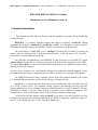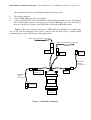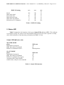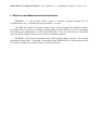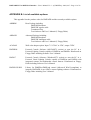
1
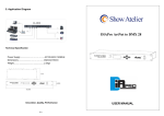
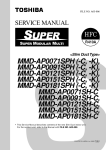
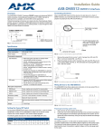
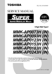
DMXADP LPT to DMX-512 Interface - User’s Manual V1.6 - (C)DMXEasy 1996,1997 - Page 1 of 12
DMXADP
A compact DMX I/F
for PC Parallel Port
Hardware User's Manual
Ver 1.6
(C) DMXEasy - Milan/Bruxelles
http://www.human-interaction.it/lighting
DMXADP LPT to DMX-512 Interface - User’s Manual V1.6 - (C)DMXEasy 1996,1997 - Page 2 of 12
THIS PAGE INTENTIONALLY LEFT BLANK
DMXADP LPT to DMX-512 Interface - User’s Manual V1.6 - (C)DMXEasy 1996,1997 - Page 3 of 12
Contents
1. GENERAL INFORMATION
4
2. UNPACKING AND INSTALLING
5
3. SLAVE MODE OPERATION
7
4. MASTER MODE OPERATION
7
5. STATUS LED
8
6. ELECTRICAL AND MECHANICAL CHARACTERISTICS
9
7. TECHNICAL DATA
10
APPENDIX A: TROUBLESHOOTING
11
APPENDIX B: LIST OF AVAILABLE OPTIONS
12
DMXADP LPT to DMX-512 Interface - User’s Manual V1.6 - (C)DMXEasy 1996,1997 - Page 4 of 12
DMXADP DMX Parallel Port Adapter
Hardware Users's Manual Version 1.6
1. General information
This manual describes the main features and the installation procedure for the DMXADP
product hardware.
DMXADP is a compact miniature adapter that allows to interface a DMX-512 lighting
equipment line through a standard PC parallel port (LPT). It is intended for general purpose
DMX interfacing and is offered with different sofware environments for different tasks.
The main feature of DMXADP is to be intelligent , meaning that all DMX-512 timing and
control tasks are performed by a dedicated microcontroller, to let the main CPU of the PC
concentrate to scene fading and sequencing.
The functions accomplished by the DMXADP are the generation of the DMX-512 signal
(Master Mode) to control a set of devices connected to the line, and the acquisition of the DMX512 signal (Slave Mode) to capture the DMX patterns generated by any traditional console, and let
them be processed by software.
All the device functions are automatically managed by dedicated machine-language drivers
provided with the hardware or integrated with the software packages (see Appendix B for details).
The DMXADP hardware allows complete control of the 512 channels defined by the DMX512 standard. The line interface is short circuit and surge voltage protected.
DMXADP is a compact enclosure that connects to the Parallel Port and is externally powered
by a 5VDC-150mA source. The standard cabling supports pass-through powering from the
Keyboard/Mouse port of the computer letting the keyboard/mouse be usable if required. This lets
DMXADP be usable on any PC (either desktop or portable) with no additional equipment. The
standard cable is able to universally connect to any keyboard connector configuration.
An optional wall-cube adapter called ACADAP is provided in case the keyboard port is not
available or not adequate for powering DMXADP. ACADAP is designed to regulate the output of
any DC or AC adapter into the +5VDC required by DMXADP.
DMXADP LPT to DMX-512 Interface - User’s Manual V1.6 - (C)DMXEasy 1996,1997 - Page 5 of 12
2. Unpacking and Installing
The DMXADP package (code ADPBPK, see Appendix C) contains the following items:
1.
2.
3.
4.
the DMXADP unit;
a DMX-Power cable (shipped already attached to the base unit);
adapters for DIN keyboard connectors;
floppy disk(s) with Test Software and Us er's Manuals.
Before installing DMXADP, verify that all of the items above are present and in good
conditions. For any problem, refer to the DMXADP dealer.
Figure 1 shows the external aspect of the DMXADP unit, outlining the connectors and
indicators accessible by the user.
STS Led
DB-25F
to DMX/PW cable
DB-25M
to PC LPT port
Figure 1 - DMXADP external view
As show, DMXADP is a very compact enclosure using the same packaging of popular RS232 gender-changer adapters. This makes moving across different computers very easy.
The external connections are done to the LPT port with the DB-25M male connector side
and to the DMX/Power cable with the DB-25F side. In the standard shipping configuration, the
DMX/Power cable is already attached at the base unit, and it may be remoded for troubleshooting
if required.
The only user visible indicator is the STS Led used that provides a visual indication of the
DMX line traffic.
DMXADP LPT to DMX-512 Interface - User’s Manual V1.6 - (C)DMXEasy 1996,1997 - Page 6 of 12
The installation process is accomplished through the following steps:
1.
2.
3.
Turn-off the computer.
Connect DMXADP to the LPT port of the PC.
Connect the DMX-PW cable to the DMX line and to the Keyboard-Mouse port. The shipped
PS/2 to DIN adapters may be removed in case of PS/2 KBD/Mouse ports. If removed, save
them in a safe place for future use of DMXADP on DIN-type KBD/Mouse ports.
Figure 2 shows the external connections of DMXADP once installation is complete (the
case of use with the Intelligent Cable option is shown, with the Base Cable a separate DMX
termination plug is required for Master mode applications).
DMX-512 outgoing line (XLR-5M)
DMX-512 incoming line (XLR-5F)
XLR-5F
DMX Out
XLR-5M
DMX In
DIN-5F to
Keyboard
PS/2-DIN
adapter
(if required )
PS/2-6F to
Kbd/Mouse
PS/2-6M to
Kbd/Mouse port
DIN-PS/2
adapter
(if required )
DIN-5M to
Keyboard port
DB-25M
to PC LPT port
Figure 2 - DMXADP connections
DMXADP LPT to DMX-512 Interface - User’s Manual V1.6 - (C)DMXEasy 1996,1997 - Page 7 of 12
3. Slave Mode operation
One of DMXADP functions is to operate as a DMX-512 signal capture device. This mode of
operation is called Slave Mode.
While in Slave Mode, DMXADP is able acquire the signal propagated from the DMX-IN
male connector. When a DMX Capture command is received from the LPT interface, the
microcontroller of DMXADP acquires the channel state from a DMX-512 line locally and then
transfers the acquired DMX frame to the CPU. All 512 channels may be captured with full 8-bit
resolution.
Given the limited dynamical capabilities of the pseudo-bidirectional mode of the PC LPT
interface, this operation is only applicable to static DMX-512 configurations and it is not meant to
acquire cross-fade profiles or one-shot DMX configurations.
In Slave Mode the DMXADP microcontroller automatically identifies the actual number of
channels (up to 512) driven by the external console and then reports back to the CPU the startcode
and the string of the acquired channels with their intensity level.
In Slave Mode the Status LED is flashed every time a valid DMX configuration has been
acquired. If no signal is found (missing signal or DMX-IN unplugged) the LED is not flashed and a
null channel count is returned as a capture timeout condition.
4. Master Mode operation
Master Mode is entered on reception of a DMX Drive command from the software. In this
case DMXADP hardware enables the internal DMX-512 line driver onto the DMX-OUT female
connector. In Master Mode the DMX line is entirely under control of DMXADP.
In Master Mode the Status LED is toggled every four packet transmission, providing a
visual indication of the DMXADP drive activity.
With the Intelligent Cable option, DMXADP has integrated source DMX-512 termination.
The termination is automatically inserted on the line whenever DMXADP is set in Master Mode. In
this case the DMX-IN line is automatically disconnected to avoid conflict on the DMX line when
DMXADP is switched between Master and Slave modes. This feature is ideal for backup
applications: when idle or switched off, DMXADP propagates the input signal from the master
console, and is ready to take control of the line (insulating master console) at any time.
With Regular Cable, an XLR female termination plug must be externally connected to the far
end male connector of the cable when driving DMX line in Master mode, and should not be
connected when operating in Slave mode. DMXADP is capable to identify the cable type and
prompt the user to disconnect DMX_IN signal and insert the termination before driving DMX.
The microcontroller of DMXADP
generates DMX-512 timing following the
recommendation of USITT-1990 standard, guaranteeing 44 frames/sec. The timing characteristics
of the signal driven by DMXADP in Master mode are specified in Table 1, with reference to the
parameters defined in the USITT-1990 standard (April 1990, reprinted June 14, 1990 by United
State Institute of Theatre Technology, Inc.). DMXADP is able to drive any DMX device that
complies with the USITT standard: in case problems are encountered with a particular DMX
device refer to the device manufactorer to investigate incompatibility with USITT-1990 timing
using Table 1 as a reference.
DMXADP LPT to DMX-512 Interface - User’s Manual V1.6 - (C)DMXEasy 1996,1997 - Page 8 of 12
DMX-512 timing
min
max
Break
Mark-after-break
Inter-frame time
Mark-between-frame
Mark-after-last-channel
Refresh rate (512-channels)
100
8
44
0
8
35
300
40
84
40
40
44
unit
us
us
us
us
us
us
Hz
Table 1 - DMX-512 timing
5. Status LED
Table 2 summarizes the functions of the green Status LED indicator (STS). This indicator
is provided to notify the result of the microcontroller Built In Self Test and to provide a steadystate visible indication of the functions performed on the DMX-512 line.
Status LED indicator state
MASTER MODE
phase
initialization in progress
BIST OK ready for command
DMX-512 transmission active
LED state
off
on
flash/4 packets
SLAVE MODE
phase
initialization in progress
BIST OK ready for command
DMX-512 acquisition in progress
acquisition done, frame transfer
transfer done, ready for next command
LED state
off
on
off
on
on
Table 2 - Status LED functions
DMXADP LPT to DMX-512 Interface - User’s Manual V1.6 - (C)DMXEasy 1996,1997 - Page 9 of 12
6. Electrical and Mechanical characteristics
DMXADP is a DC-powered device. Power is normally supplied through the PC
keyboard/mouse port. Maximum current requirement is 150mA.
The DMX line interface is transient voltage and AC short protected. This minimizes chances
to damage the PC in presence of voltage transients induced on the DMX line or of user miscabling
that could result in shorting the AC line on the DMX lines. In any case maximum care should be
put in the DMX cabling to satisfy safety and noise immunity standards.
DMXADP is housed in the standard format DB-25 gender-changer enclosure. The external
dimensions (54mm wide x 17mm high x 63mm deep) make DMXADP very easily connected to all
PC models, including very compact, battery operated notebooks.
DMXADP LPT to DMX-512 Interface - User’s Manual V1.6 - (C)DMXEasy 1996,1997 - Page 10 of 12
7. Technical data
DMXADP V1.0
TECHNICAL DATASHEET
Features
Intelligent microcontroller-based DMX IN/OUT interface
Connectors
LPT: DB-25M Standard Parallel Port
DMX/PW: DB-25F to DMX-in/DMX-out/Power
Indicators
LED: Built-In-Self-Test and DMX line traffic
DMX-512 interface
RS-485 compatible, 250Kbit/s surge and AC-short protected
Power
External 5VDC, 150mA (through provided Keyboard/Mouse port
adapter cables or via optional ACADAP wall-cube adapter)
Dimensions
54mm(W) x 17mm(H) x 63mm(D)
Weight
100g
DMXADP LPT to DMX-512 Interface - User’s Manual V1.6 - (C)DMXEasy 1996,1997 - Page 11 of 12
APPENDIX A: Troubleshooting
This appendix gives instructions on how to resolve some simple situations that the user may
encounter when using DMXADP. For problems that cannot be resolved using this section, refer to
your DMXADP dealer.
T1: Turning on the PC, the STS LED does not turn on
This indicates that either the DC power is not properly applied to DMXADP or the internal
microcontroller has not passed Buil-In-Self-Test. Make sure DMXADP cable is properly
connected to the Keyboard/Mouse port and recheck. Try on a different PC to exclude a
defective Keyboard/Mouse port. If available, try with the external wall-cube adapter
(ACADAP). If after checking power the LED does not turn-on, contact your dealer for
assistance.
T2: The DMXADP software reports "Sense Timeout" errors
Someting is wrong in the communication between the PC and DMXADP. Check the
connection of the LPT connector. Avoid switching power off to DMXADP while PC is still
on: always power on DMXADP while powering on the PC. If the problem persists, contact
your dealer for assistance.
T3: In master mode, no signal is detected by DMX receivers (dimmers, etc.)
If a new DMX appliance (receiving module) is being used, check it for full compliance with
USITT DMX-512/1990. If the module is presumed to conform to the specification, verify the
output of DMXADP in Master Mode with a DMX tester or another DMXADP used in Slave
Mode. If problems are found with the DMX signal, contact your dealer for assistance. There
are no user-replaceable parts inside DMXADP.
DMXADP LPT to DMX-512 Interface - User’s Manual V1.6 - (C)DMXEasy 1996,1997 - Page 12 of 12
APPENDIX B: List of available options
This appendix lists the product codes for DMXADP and the currently available options.
ADPBPK
Base Package including:
DMXADP hardware
DMX/PW regular cable
Terminator Plug
Test Software and User’s Manual (2 Floppy Disks)
ADPAPK
Advanced Package including:
DMXADP hardware
DMX/PW intelligent cable
Test Software and User’s Manual (2 Floppy Disks)
ACADAP
Wall-cube adapter option. Input 7.5-15VAC or VDC, output 5VDC
DMXDOS
Personal Console Software (MS- DOS™ version) to turn the PC in a
Personal Lighting Console capable of DMXOut and DMXIn. Distributed on
Floppy Disks including Software User’s Manual
DMX97
Personal Console Software (Windows95™ version) to turn the PC in a
Personal Visual Lighting Console capable of DMXOut and DMXIn with
integrated scanner and multimedia control features. Distributed on Floppy
Disks including Software User’s Manual
DMXPLUS.DLL
Library for DMXPlus/DMXAdp control (Microsoft Win32-compliant) to
integrate DMXADP in an OEM’s custom lighting software. Distributed on
Floppy Disks including User’s Manual.