1
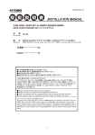
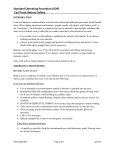
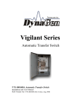
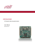
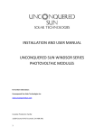
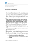
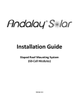
Installation | Safety instructions | Maintenance
Photovoltaic modules user manual
Conergy S 175/180MU/Conergy Q 85MU
Please carefully read the following installation and safety instructions.
Non-compliance with these instructions may void the module warranty.
Purpose of this guide
This guide contains information regarding the installation and safe handling of
Conergy photovoltaic modules (hereafter referred to as "modules"). All
instructions should be read and understood before attempting installation. If there
are any questions, please contact your dealer or Conergy for further information.
The installer should conform to all safety precautions in the guide when installing
modules. Before installing a solar photovoltaic system, the installer should
become familiar with the mechanical and electrical requirements for photovoltaic
systems. Keep this guide in a safe place for future reference.
General
| Installing solar photovoltaic systems requires specialized skills and knowledge.
The installer assumes all risk of injury, including risk of electric shock. Module
installation should be performed only by qualified persons.
| All modules come with a permanently attached junction box and #12 AWG
(4 mm²) wire terminated in Multi Contact PV connectors. Your dealer can
provide additional extension cables to simplify module wiring.
| Each individual module can generate DC voltages greater than 30 volts (V)
when exposed to direct sunlight. Contact with a DC voltage of 30 V or more is
potentially hazardous. Exercise caution when wiring or handling modules
exposed to sunlight.
| When disconnecting wires connected to a photovoltaic module that is exposed
to sunlight, an electric arc may occur. Arcs can cause burns, start fires or
otherwise create safety problems. Exercise caution when disconnecting wiring
on modules exposed to sunlight.
| Photovoltaic solar modules convert light energy to direct-current electrical
energy, and are designed for outdoor use. Proper design of support structures
is the responsibility of the system designer and installer.
| Modules may be ground mounted, pole mounted, or mounted on rooftops.
Do not attempt to disassemble the module, and do
not remove any attached nameplates or components.
Doing so will void the warranty.
| Do not apply paint or adhesive to the module.
Do not use mirrors or other hardware to artificially
concentrate sunlight on the module.
| When installing modules, observe all applicable local, regional and national
codes and regulations. Obtain a building and/or electrical permit where required.
Safety precautions for installing a solar photovoltaic system
| Solar modules produce electrical energy when exposed to sunlight.
DC voltages may exceed 30V on a single exposed module.
| Only connect modules with the same rated output current in series.
If modules are connected in series, the total voltage is equal to the sum of
the individual module voltages.
| Only connect modules or series combinations of modules with the same
voltage in parallel. If modules are connected in parallel, the total current is
equal to the sum of individual module or series combination currents.
| Keep children well away from the system while transporting and installing
mechanical and electrical components.
| Completely cover all modules with an opaque material during installation to
prevent electricity from being generated.
Do not wear metallic rings, watchbands, ear, nose, or
lip rings or other metallic devices while installing or
troubleshooting photovoltaic systems.
| Observe the instructions and safety precautions for all other components
used in the system, including wiring and cables, connectors, DC-breakers,
mounting hardware, inverters, etc.
| Use only equipment, connectors, wiring and mounting hardware suitable for
use in a photovoltaic system.
| Always use the same type of module within a particular photovoltaic system.
| Under normal operating conditions, PV modules will produce currents and
voltages that are different than those listed in the date sheet. Data sheet
values are applicable at standard test data.
| Short-circuit current and open-circuit voltages should be multiplied by a factor
of 1.25 when determining component voltage ratings, conductor ampacity,
fuse sizes and size of controls connected to the module or system output.
Refer to Section 690-8 of the National Electrical Code (NEC) for an additional
multiplying factor of 125 percent (80 percent de-rating) which may be applicable.
General installation notes
| Drainage holes must not be covered with parts of the mounting system. The
junction box has a breather port which must be mounted facing downward and
cannot be exposed to the rain. The junction box should be on the higher side of
the module when it is mounted in order to orient the breather port correctly.
| Do not lift the module by grasping the module's junction box or electrical leads.
| Do not stand or step on module.
| Do not drop the module or allow objects to fall on the module.
| Do not place any heavy objects on the module.
| Inappropriate transport and installation may damage the module glass or frame.
Mechanical Installation
Selecting the location
| Select a suitable location for installation of the module.
| For optimum performance, the module must be facing true south in northern
latitudes and true north in southern latitudes.
| For detailed information on optimal module orientation, refer to standard solar
photovoltaic installation guides or a reputable solar installer or systems integrator.
| The module should not be shaded at any time of the day.
| Do not install the module near equipment or in locations where flammable gases
can be generated or collected.
Selecting the proper mounting structure and hardware
| Observe all instructions and safety precautions included with the mounting
system to be used with the module.
| Do not drill holes in the glass surface of the module. Doing so will void the warranty.
| Do not drill additional mounting holes in the module frame. Doing so will void the
warranty.
| Modules must be securely attached to the mounting structure using four
mounting points for normal installation. If heavy wind or snow loads are
anticipated, additional mounting points should also be used. Please see the
drawing below.
| Load calculations are the responsibility of the system designer or installer.
| The mounting structure and hardware must be made of durable, corrosion- and
UV-resistant material.
Mounting methods
1. Mounting With Bolts
| The module must be attached and supported by at least four bolts through
the indicated mounting holes.
| Most installations will use the four inner mounting holes on the module frame.
| Depending on the local wind and snow loads, additional mounting points may
be required.
Use appropriate safety equipment (insulated tools,
insulating gloves, etc) approved for use on electrical
installations.
Page 1/2
Installation | Safety instructions | Maintenance
Photovoltaic modules user manual
Conergy S 175/180MU/Conergy Q 85MU
150
150
2. Mounting With Clamping Hardware
| If module clamps are used to secure the module, the torque on the clamp bolt
should be around 8–10 Nm.
| A minimum of four module clamps should be used, two on each long frame side,
in the general clamping areas denoted by the wide arrows on the drawing.
| Depending on the local wind and snow loads, additional module clamps may be
required.
485
485
each
900 mm
cable
485
Maintenance
Conergy recommends the following maintenance items to ensure optimum
performance of the module:
| Clean the glass surface of the module as necessary. Use water and a soft
sponge or cloth for cleaning. A mild, non-abrasive cleaning agent can be
used if necessary. Do not use dishwasher detergent.
| Electrical and mechanical connections should be checked periodically by
qualified personnel to verify that they are clean, secure and undamaged.
| Check the electrical and mechanical connections periodically to verify that
they are clean, secure and undamaged.
| Problems should only be investigated by qualified personnel.
| Observe the maintenance instructions for all other components used in the
system.
Shutting down the system
| Completely cover system modules with an opaque material to prevent
electricity from being generated while disconnecting conductors.
| Disconnect system from all power sources in accordance with instructions
for all other components used in the system.
| The system should now be out of operation and can be dismantled. In doing
so, observe the all safety instructions as applicable to installation.
150
150
485
WARNING!
Electrical shock hazard! Do not touch bare conductors
or other potentially energized parts.
Electrical ratings of the concerned modules:
All dimensions in mm
3. Other
| Other mounting methods are acceptable as long as the minimum requirement
as described under 2. Mounting with clamping hardware are met.
MODUL_Installation-UL-IM-ENG-0705
Electrical Installation
Grounding
| All module frames must be properly grounded.
| Observe all local electric codes and regulations.
| A bonding or toothed washer is required to make proper and reliable electrical
grounding connection with the anodized aluminum frame.
| Devices listed and identified for grounding metallic frames of PV modules are
permitted to ground the exposed metallic frames of the module to grounded
mounting structures. Per NEC 250.136, electrical equipment secured to and in
electrical contact with a metal rack or structure provided for its support and
grounded by one of the means indicated in 250.134 shall be considered
effectively grounded.
| Consider using a lay-in lug, rated for outdoor use (Illsco
GBL4 DBT or equivalent), if the module grounding conductor
is to be larger than #10 AWG.
| When using lay-in lugs, the grounding conductor should
be inserted into the opening indicated in the figure, and
secured using the set screw.
General electrical installation
| Do not use modules of different configurations in the same system.
| This module is supplied with Multi Contact connectors for electrical connections.
| Refer to Section 690.31 of the NEC to determine appropriate types and
temperature ratings of conductors. Wiring should be #12 AWG, 4 mm²
(minimum) and must be temperature rated at 90 °C (minimum).
| Completely cover system modules with an opaque material to prevent
electricity from being generated while disconnecting conductors.
| Refer to Sections 690.8 and 310 of the NEC to determine overcurrent,
conductor ampacity and size requirements.
| In Canada, installation shall be in accordance with CSA C22.1, Safety
Standard for Electrical Installations, Canadian Electrical Code, Part 1.
| For best performance, ensure that positive and negative DC wires run
closely together avoiding loops.
www.conergy.com | 2007 © Conergy AG
Maximum Power (PMPP)
Output Tolerance
Rated Voltage (VMPP)
Rated Current (IMPP)
Open Circuit Voltage (VOC)
Short Circuit Current (ISC)
Maximum System Voltage
Maximum Series Fuse Rating
Fire Class
S 180MU
180 W
–2/+ 3 %
35.6 V
5.05 A
44.4 V
5.4 A
600 V
15 A
C
175MU
175 W
–2/+ 3 %
35.2 V
4.95 A
44.2 V
5.2 A
600 V
15 A
C
Q 85MU
85 W
+/- 5 %
17.6 V
4.83 A
21.9 V
5.14 A
600 V
15 A
C
The electrical characteristics are within ±10 % of the indicated values of ISC, VOC, and Pmax under Standard Test
Conditions (irradiance of 1000 W/m2, AM 1.5 spectrum, and a cell temperature of 25°C/77°F)
Disclaimer of liability
Because the use of this manual and the conditions or methods of installation,
operation, use and maintenance of photovoltaic products are beyond Conergy's
control, Conergy does not accept responsibility and expressly disclaims liability
for loss, damage, or expense arising out of or in any way connected with such
installation, operation, use or maintenance. No responsibility is assumed by
Conergy for any infringement of patents or other rights of third parties, which may
result from use of the PV product. No license is granted by implication or otherwise
under any patent or patent rights.
The information in this manual is based on Conergy's knowledge and experience
and is believed to be reliable, but such information including product specification
(without limitations) and suggestions does not constitute a warranty, expressed
or implied. Conergy reserves the right to change the manual, the product, the
specifications, or product information sheets without prior notice.
Information about manufacturer:
Conergy Inc.
1730 Camino Carlos Rey, Suite 103
Santa Fe, NM 87507
USA
www.conergy.us
Please consult your dealer or the manufacturer concerning the warranty of your
modules. If you have any further questions, your dealer will gladly assist you.
Subject to technical modifications without notice. 2007 © Conergy, Inc.
Page 2/2