1
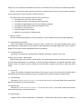
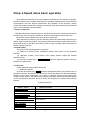
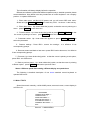
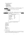
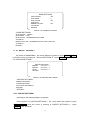
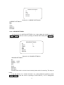
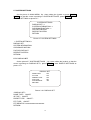
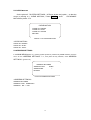
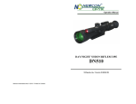
High speed dome camera
User manual
※Please read the user manual carefully before use it;Please keep this manual for easy access when
necessary.
1
Content
Chap.1 Foreword ........................................................................................................................................... 2
Chap.2 Product overview .............................................................................................................................. 4
2.1 Product brief description ................................................................................................................ 4
2.2 Performance characteristics .......................................................................................................... 4
2.3 Function explanation...................................................................................................................... 5
2.4 Technical parameter ...................................................................................................................... 7
Chap.3 Installation ......................................................................................................................................... 7
3.1 Speed dome DIP switch settings ........................................................................................................ 7
3.1.1 Enter DIP switch settings .......................................................................................................... 8
3.1.2 DIP switch settings ................................................................................................................... 8
Chap. 4 Speed dome basic opration ............................................................................................................. 9
Chap. 5 Menu settings+ ................................................................................................................................. 11
5.1 Main menu ...................................................................................................................................... 12
5.2 < CAMERA SETTINGS > ............................................................................................................... 13
5.3 < OTHER SETTINGS >.................................................................................................................. 13
5.4 < CAMERA LENS>......................................................................................................................... 13
5.5 < DOME SETTINGS > ................................................................................................................... 14
5.6 <MOTION SETTINGS> .................................................................................................................. 15
5.6.1<PRESET SETTINGS> .................................................................................................................. 16
5.6.2<CRUISE SETTINGS> ................................................................................................................... 16
5.6.3<SCAN SETTINGS> ....................................................................................................................... 17
5.7 SYSTEM SETTINGS ........................................................................................................................ 18
5.7.1 DISPLAY SET ....................................................................................................................... 18
5.8 CLEAR MOTION ............................................................................................................................. 18
5.9 ADDRESS SETTINGS .................................................................................................................... 19
Chap.6 Simple fault clearing and maintain .................................................................................................... 20
6.1 Simple fault clearing form ................................................................................................................. 20
6.2 Notes ................................................................................................................................................. 20
6.3 After service .......................................................................................................................................... 21
2
Chap.1
Foreword
Before install and use high speed PTZ camera, please read below information carefully.
1.Before installation please read user manual carefully.
2.Please do not test and install the product on unstable flat,make sure the product place on a stable flat
and assembly firmly before operation.
3. Prevent products damage caused by stress, severe vibration and immersion on transportation and
storage.
4. Installation of this product must not be reversed;please handle with care,do not squeeze structural
components,Otherwise, they may cause mechanical failure, affecting the overall performance. The
transparent material on the speed dome iris is advanced optical materials,do not touch it, any scratches
will affect image quality.
5. Prevent any foreign matter or liquid into camera, to avoid damage on camera.
6. When you make connection, please follow up safety standards, use with a dedicated power supply.
RS-485 and video signal adopt TVS grade lightening protection technique, can effectively prevent damage
caused by not more than 500W lighting, surging and other types of pulse signals. Please keep enough
distance away from High-voltage equipment or cables when RS-485and video signals during transmission.
Make lighting and surging protection measures when necessary.
7. Whether in use or non-use, never allow cameras aimed at the sun or other bright objects。Otherwise,
may result in permanent damage of CCD
8.Do not use it exceed the temperature, humidity standards.
9. This product do not have user repair parts。When camera has fault,please do not repair it,should find
out fault refer to user manual,if cannot find out reason, please send the camera to professional
maintenance person. The maintenance person must be authorized by our company.
3
Chap.2 Product overview
2.1 Product introduction
High speed PTZ camera adopt the latest scientific and technological achievements, best manufacturing
technique, successful developed by years of valued experience,it is a high-performance digital signal
processing (DSP) camera which equips with automatic zoom lens;build-in PTZ and digital decoders,
representing a new generation of high-tech monitoring products. It uses all-digital control, simple and
ingenious design, discretional quickly locate and continuous follow-up scan, it has automatic tracking
function,make smart surveillance of all-round, non-blind spot, Can automatically adapt to the environment
and target distance changes in light and dark, High reliability and long-term stable operation, without
maintenance.
High speed PTZ camera is compatible with a variety of control protocols, so it can support a variety of
popular platforms. Match with other system,the connection use methods of different system is not the
same, please contact the system manufacturer or distributors for necessary information.
The various characteristics of the high speed PTZ camera , make it applicable to large-scale industries,
active target object surveillance。Such as power systems, telecommunications sector, banking security,
factories and enterprises, intelligent buildings, intelligent community, urban road monitoring, airports,
stations and other monitoring occasions.
2.
.2
Feature
1. Build-in OSD English menu, through menu to display and change the information and parameter of
camera, can set and CALL presets, pattern scan, area scan and display area etc.
2. Integrated design, compact structure and high reliability.
3. 255 presets
4. Adopt RS485 control
5. Precision motor drive, running smoothly and responsive.
6. Horizontal 360°continuous rotation, no surveilla nce blind area
7. Rotation speed automatic adjust according to lens’ zoom
8. Vertical 90°,auto overturn 180°continuous surveillance.
9. Auto focus, auto white balance
10. Backlight compensation, you can see all the objects in a strong light environment.
11. Auto-identify PELCO-D/P communication protocols, baud rate between 2400bps~19200bps
optical
12.Wide Dynamic Camera Support(SONY1010、SONY490、SONY990)
4
2.
.3
Function
Below is a brief introduction of high speed PTZ camera main function, achievement and operation
principles of each function, does not involve a specific method of operation.
1. Setup address code, baud rate, control protocol
Any operation commands has camera address code, baud rate and control protocol, any single
camera only respond to its own address code, baud rate, control protocol command. The detailed setup
ways of camera address code, baud rate and control protocol please refer to DIP switch settings.
2.Tacking
User can use the keyboard joystick to control the camera turning up, down, left or right, Can be used
to track moving targets or moving horizon, in addition you can change the eyeshot size and image size by
adjusting the focal length. In the auto-focus state, with the lens rotation, the camera will automatically
quickly adjust according to scenery change, instantly get a clear picture.
3.Focal length / rotation speed automatic matching technique
Manual adjustment, in long focal length situation, high speed reflect makes image quickly move
when a slight touch of joystick, resulting a data loss. Based on a humanized design, the PTZ camera can
automatically adjust horizontal and vertical rotation speed according to focal length, so that manual
operation is simple and easy to track targets.
4.Auto Invert
The operator pull the lens to bottom (vertical) and still hold the joystick, lens auto horizontal overturn
180°then downward overturn 90°,direct see the back of scenery, achieve vertical 180°full continuous
monitoring.
5.Setup and CALL presets
Preset function means speed dome can store horizontal and tilt angle of platform as well as camera lens
focal length and other parameters in memory, you can quickly CALL these parameters and adjust platform
and camera to the location. User can easily and quickly control equipment to storage and CALL preset via
keyboard and IP controller, this high speed PTZ has 256 presets.
6.Lens control
1)Focal length control
User can adjust the focal length via keyboard and matrix, in order to receive the necessary panoramic
images or micro-lens image.
2)Focus control
System default auto-focus, zoom, camera lens will automatically focus to the centre of scene, keep
5
image clear; In exceptional circumstances the user can manually focus to achieve the desired image effect.
When in manual focus state, sway the control bar to restore the auto-focus. There are also a dedicated
control commands or CALL a preset to restore auto focus.
The camera lens in the following situations will not auto focus:
a.The object does not in the centre of image;
b.The object in the near and far place at the same time;
c.The object is bright objects, such as neon lighting, spotlights;
d.The object is behind glass which with droplets or dust;
e.The object is moving too fast;
f.Large area object, such as wall;
g.Objectives are too dark or inherently dim.
7.Aperture control
User can manual adjust aperture size via keyboard in order to obtain the required image brightness.
8.Auto backlight compensate
When the backlight compensation function is open, camera lens in the light background can make
auto brightness compensation to dark objective. Make adjustment to bright background, avoid a mass of
brightness and object cannot identifiable because of darkness.
9.Auto white balance
According to the changes in ambient light, automatic adjustment, reproduce true color
10.Night vision function(B/W switch)
Camera with night vision function, at B/W mode, it will automatically switch CCD illumination according
to environment light changes. For example, in the day, the light is adequate, use general illumination keep
images colorful. At night it will auto change to low illumination, display scene clear in black and white
image.
11.Auto Tour
Pre-set Tour presets, arrange some presets to Tour queue in order, only a command can make indoor
intermediate speed dome constant movement in specified time interval according to presets order.
12.A-B Scanning
Through an external command or power-on or call free time Auto-running, it can make speed dome camera A-B
Scanning continually in horizontal direction
13. 360°Scanning
Through an external command or power-on or call free time Auto-running, it can make speed dome camera
360°rotate continually in horizontal direction
14. Wide Dynamic
Support SONY newest FCB-EC490,FCB-EC990,FCB-EC1010 wide dynamic camera, applied in
6
strong cockfighting environments.
2.
.4 Technical parameter
Product
Name
Intelligent High Speed Dome Camera
Product
Model
VT-GV
PTZ
Address
1~255
Communication Baud rate
2400/4800/9600/19200bps
Communication Mode
Communication Protocols
RS485 bus control
Recognize Pelco-P, Pelco-D automatically
Auto flip
System soft restart
Yes
Yes, recover to the status before power off automatically
System power-off protect
Auto-running during free time
360°auto-scanning
Yes
Yes, preset ,A-B scanning, cruise scanning and so on
Auto-adjust the scanning speed du ring zooming
Manual horizontal speed
0.5°~260°/s
Manual vertical speed
0.5°~180°/s
Rotation range
Zoom self-adaption
H: 0~360° V: 0 ~90°
auto-adjust the PTZ control speed during zooming
A-B scanning
4pcs
Presets
255(accuracy ±0.1°)
Preset speed
Max :280°/s
Preset residence time and
preset speed
Preset residence time :0~255s
Preset Speed: 1~63 speed level adjustable
Auto cruise
Anti-surge function
8pcs,each cruise line has 16presets
Three level anti-static, anti-surge, lightning protection
Power supply
DC12V
Work environment
-10℃~+55℃,﹤95%RH
Water-proof level
IP66
Dimension
6inch
Chap.3 Installation
3.1 Speed dome DIP switch settings
High speed dome camera is compatible with a variety of control protocols, baud rate can be adjusted to
make it compatible with more monitoring and control system。Before install the speed dome camera,
please adjust the DIP switch to appropriate code according to your requirements, in order to adjust the
7
baud rate, control protocol, address code. If there are no special requirements, the speed dome factory
default address code is 1, baud rate is 2400BPS corresponding code, and control protocol is PELCO-D
corresponding code.
3.1.1 Enter DIP switch settings
Through DIP switch can change BAUD-RATE, PROTOCOL and ADDRESS. Speed dome core,
housing and DIP switch pictures see picture 1.
Picture1 Dome core and DIP switch
3.1.2 DIP switch settings
SYS:Baud rate and control protocol switch
ADDS:Address code switch
DIP switch “ON” means “1”,DIP switch “OFF”means“0”, DIP switch left is low position ,right is high
position
Baud rate and control protocol setting form:
SYS
Code
point
1
2
Control
protocol
BPS
3
4
OFF
OFF
self-adapting
ON
OFF
PELCO-D
OFF
ON
PELCO-P
ON
ON
Reservation
OFF
OFF
2400
ON
OFF
4800
OFF
ON
9600
ON
ON
19200
2. ADDS is used for setting speed dome address code。Address adopt binary mode, you can set at total
255 different speed dome address code, see address code table. The factory default setting is as below.
8
Address
code
ADDS speed dome address code table
1
2
3
4
5
6
7
8
1- adapting
OFF
OFF
OFF
OFF
OFF
OFF
OFF
OFF
1
ON
OFF
OFF
OFF
OFF
OFF
OFF
OFF
2
OFF
ON
OFF
OFF
OFF
OFF
OFF
OFF
3
ON
ON
OFF
OFF
OFF
OFF
OFF
OFF
4
OFF
OFF
ON
OFF
OFF
OFF
OFF
OFF
5
ON
OFF
ON
OFF
OFF
OFF
OFF
OFF
6
OFF
ON
ON
OFF
OFF
OFF
OFF
OFF
7
ON
ON
ON
OFF
OFF
OFF
OFF
OFF
8
OFF
OFF
OFF
ON
OFF
OFF
OFF
OFF
9
ON
OFF
OFF
ON
OFF
OFF
OFF
OFF
10
OFF
ON
OFF
ON
OFF
OFF
OFF
OFF
11
ON
ON
OFF
ON
OFF
OFF
OFF
OFF
12
OFF
OFF
ON
ON
OFF
OFF
OFF
OFF
13
ON
OFF
ON
ON
OFF
OFF
OFF
OFF
14
OFF
ON
ON
ON
OFF
OFF
OFF
OFF
15
ON
ON
ON
ON
OFF
OFF
OFF
OFF
16
OFF
OFF
OFF
OFF
ON
OFF
OFF
OFF
17
18
ON
OFF
OFF
ON
OFF
OFF
OFF
OFF
ON
ON
OFF
OFF
OFF
OFF
OFF
OFF
19
ON
ON
OFF
OFF
ON
OFF
OFF
OFF
20
OFF
OFF
ON
OFF
ON
OFF
OFF
OFF
21
ON
OFF
ON
OFF
ON
OFF
OFF
OFF
22
OFF
ON
ON
OFF
ON
OFF
OFF
OFF
23
ON
ON
ON
OFF
ON
OFF
OFF
OFF
24
OFF
OFF
OFF
ON
ON
OFF
OFF
OFF
25
ON
OFF
OFF
ON
ON
OFF
OFF
OFF
26
OFF
ON
OFF
ON
ON
OFF
OFF
OFF
27
ON
ON
OFF
ON
ON
OFF
OFF
OFF
28
OFF
OFF
ON
ON
ON
OFF
OFF
OFF
246
OFF
ON
ON
OFF
ON
ON
ON
ON
247
ON
ON
ON
OFF
ON
ON
ON
ON
248
OFF
OFF
OFF
ON
ON
ON
ON
ON
249
ON
OFF
OFF
ON
ON
ON
ON
ON
250
OFF
ON
OFF
ON
ON
ON
ON
ON
251
ON
ON
OFF
ON
ON
ON
ON
ON
252
OFF
OFF
ON
ON
ON
ON
ON
ON
253
ON
OFF
ON
ON
ON
ON
ON
ON
254
OFF
ON
ON
ON
ON
ON
ON
ON
255
ON
ON
ON
ON
ON
ON
ON
ON
9
Chap. 4 Speed dome basic operation
Since different platforms of concrete operation methods are not identical, generally,
should be based on the system manufacturer's operating manual prevail under different
circumstances will have special requirements and methods of the operation, please
contact the dealer to obtain the necessary information. Here only introduced the keyboard
how to control the ball machine method.
1. Power on Self Test
After the speed dome camera power on, the camera process the horizontal and vertical
movement by auto, through the self-test to determine speed dome camera work fine.
Control the camera rotation from top to bottom, right to left:
After selected one camera, you can manually control the speed dome camera top to
bottom, right to left by the joystick .The joystick control the movement of the camera, when
the joystick shake to the right, the camera is also to right. Similarly, when the joystick to
the left, camera same too.
2. Preset setting
According to the following steps to set preset:
(1) Select the camera (more information please read control of the keyboard
manual);
(2) Operation joystick, zoom button, focus button, buttons adjust the camera
aperture screen;
(3) Press the number key ++SHIFT+ CALL (Enter the specified preset), save the
preset scene parameters.
3. Call preset
Follow the below step to watch the preset:
(1)select the camera;
(2) Press the number key +CALL (enter the designated preset), the camera move to
the present position immediately, the lens zoom, focus and aperture is also automatically
change to the preset parameters; if the input is a special function of the preset (see
"Preset function menu"), the speed dome camera will perform with special features preset
of the corresponding functions (such as: Enter the 80 preset, the camera auto-tracking
feature).
Preset function list
Special
preset
Specific of function
CALL 64/95 PRESET
Enter dome camera menu
CALL 57 PRESET
Enter camera menu
CALL 56 PRESET /IRIS-
Mandatory exit menu
CALL 97/99 PRESET
Start Auto scan
CALL 96 PRESET OR OTHER
PTZ CONTROL
Stop auto scan
CALL 49 PRESET
Start Tour function 1
CALL 50 PRESET
Start Tour function 2
CALL 51 PRESET
Start Tour function 3
10
CALL 52 PRESET
Start Tour function 4
SET 54 PRESET
Set left/right scan 1 start
SET 55 PRESET
Set left/right scan 1 end
CALL 54 PRESET
Start left/right scan 1
CALL 55 PRESET
Start left/right scan 2
CALL 61 PRESET
Reboot system
CALL 60 PRESET
Recovery default parameters
SET 64/95 PRESET, CALL 96
PRESET
Set signal system and the protocol of camera module
4.
.Close-up lens and wide-angle lens
Zoom adjustment, or to narrow the disparity between the camera lens, zoom in or
out the scenery to get close-up and wide-angle effect. Hold down the ZOOM+ , the
camera features are closer to the picture of the object is magnified; hold the ZOOM- , the
camera features pulled away, the screen object has been reduced. If you press and
quickly release the zoom button, the camera monitor screen only for small changes. The
camera zoom changes depends on the length of time holding down the zoom button
.
5.
.Lens Focus Control
Focus is adjustable camera images of an object or scene in the clarity of the process.
Hold down the FOCUS+ from the distant objects or scenes clear up near objects become
blurred. Hold down the FOCUS-, proximity to clear up objects or scenes, distant objects
become blurred. Focus button repeatedly until you adjust the monitor screen objects into
clear from the ambiguity. The same as the zoom button, the camera focused vary
depending on the length of time holding down the focus button.
6.
.Manual Iris Function
The camera aperture will change the brightness of the screen. Hold down the IRIS+ ,
the camera picture change to light, hold down the IRIS- , the camera screen change to
dimmed. The same as the zoom button, the camera light dark vary depending on the
length of time holding down the aperture button.
Chap. 5 Menu settings
This chapter will introduce the operation of OSD menu. Plug in power, after speed
dome self-test, you will see below information:
SYSTEM INFOMATIO
Camera ID
1
Protocol
PELCO-D
Baud Rate
2400
Cam Protocol
1
Version
V601
Initializing......
11
The information will always display before the operation.
Different surveillance systems has different operation ways, detailed operation please
contact distributor. Here below is an easy introduction of control keyboard(our company
product)to operate OSD menu.
1.Enter main menu: call No.64/ 95 preset, and you will enter OSD main menu.
Shake left /right FOCUS+ /FOCUS-Is the enter key. IRIS-(iris close)is the exit key.
2.Enter other menu:Up / down shake the joystick, so that the cursor is pointing to a
menu,press FOCUS+ enter the menu.
3.Function select:Up / down shake the joystick or press ZOOM+ / ZOOM-, so that
the cursor is pointing to a menu,press FOCUS+ select this function.
4.Parameter select:Up / down shake the joystick or press FOCUS+/ FOCUS- to
select the parameter
5 . Restore settings : Press IRIS+ ,restore the settings , it is effective if has
corresponding prompt.
6.Does not restore and back to last menu: press IRIS- back to last menu, it is effective
if has corresponding prompt.
7.Exit menu: Up / down shake the joystick,so that the cursor is pointing to exit option,
press IRIS+ exit OSD menu.
8.Back to previous menu:Up / down shake the joystick, so that the cursor is pointing
to Return option,press FOCUS+ and back to previous menu.
Notes:Different speed dome setting, different display on speed dome.
The following is detailed description of use smart standard control keyboard to
operate OSD menu:
5.1 Main
menu
Speed dome work normally, call No.64/95 preset, enter main menu, screen display is
as Picture 3.1
MAIN MENU
CAMERA SETTINGS--->
CAMERA LENS--->
DOME SETTINGS--->
MOTION SETTINGS--->
SYSTEM SETTINGS--->
ADDRESS SETTINGS --->
EXIT
Picture 3.1 <MAIN MENU>
12
Main menu contents description:
< CAMERA SETTINGS>:
< CAMERA LENS >:
< DOME SETTINGS >:
<MOTION SETTINGS >:
< SYSTEM SETTINGS >:
< ADDRESS SETTINGS >:
<EXIT>:
1.On the picture 3.1MAIN MENU,Up / down shake the joystick or press
ZOOM+/ZOOM-,so that the cursor is pointing to a menu item or function option;
2.Press FOCUS+,enter menu or operate a function option.
5.2 < CAMERA SETTINGS >
On the picture 3.1MAIN MENU , Up/down shake the joystick or press
ZOOM+/ZOOM-,so that the cursor is pointing to CAMERA SETTINGS--->,press FOCUS+,
enter picture 3.2 CAMERA SETTINGS.
CAMERA SETTINGS
CAMERA TYPE
ZOOM SPEED
DIGITAL ZOOM
FOCUS MODE
DAY/NIGHT
BLC
FRAME PILE
OTHER SETTINGS
RETURN
AUTO
HIGH
ON
AUTO
AUTO
OFF
OFF
-->
Picture 3.2 < CAMERA SETTINGS >
<CAMERA SETTINGS>
CAMERA TYPE:
ZOOM SPEED:
DIGITAL ZOOM:
FOCUS MODE:
DAY/NIGHT :
BLC :
FRAME PILE :
OTHER SETTINGS :
RETURN:
5.3 <OTHER SETTINGS>
1.
In the MAIN MENU(picture 3.1), rock the joystick up/down or press the key ZOOM+/ZOOM-, move
the arrow to the AMERA SETTINGS--->, then press the key FOCUS+, enter OTHER
SETTINGS to set the other parameter of camera module(picture 3.3 )
13
OTHER SETTINGS
SYSTEM SYNC
M/D MODE
WDR MODE
ANTISHAKE
RETURN
INTERNAL
OFF
OFF
OFF
<OTHER SETTINGS>
SYSTEM SYNC: INTERNAL/LINELOCK
M/D MODE: ON/OFF
WDR MODE: ON/OFF
ANTISHAKE:ON/OFF
RETURN:
5.4 CAMERA LENS
In the MAIN MENU(picture 3.1), rock the joystick up/down or press the key ZOOM+/ZOOM-, move the
arrow to the CAMERA LENS--->, then press the key FOCUS+, enter CAMERA LENS to set the
high parameter of camera module(picture 3.4 )
CAMERA
EXPOSURE
SHUTTER
APERTURE
BRIGHT
WB
BED GAIN
BLUE GAIN
RETURN
LENS
AUTO
AUTO
<CAMERA LENS>
EXPOSURE: AUTO/AE PREFs/AI PREFs/BRIGHT
SHUTTER:
APERTURE:
BRIGHT :
WB: AUTO/INDOOR/OUTDOOR/PUSH/
BED GAIN :
BLUE GAIN:
RETURN:
5.5 <DOME SETTINGS>
On the picture 3.1 MAIN MENU, Up/down shake the joystick or press
ZOOM+/ZOOM-,so that the cursor is pointing to DOME SETTINGS---> ,press FOCUS+,
enter 3.5 DOME SETTINGS
14
DOME SETTINGS
AUTO INVERT
IDLE TIMER
IDLE ACTION
ACTION No.
REBOOT ACTION
ACTION No.
RETURN
ON
0
NO
NO
Picture 3.5 <DOME SETTINGS>
<DOME SETTINGS>
AUTO INVERT: ON/OFF
IDLE TIMER: 0~255,
IDLE ACTION: NO/PRESET/SCAN/ TOUR
ACTION No.:
REBOOT ACTI ON: NO/PRESET/SCAN/ TOUR /LAST STA
ACTION No.:
RETURN:
5.
.6 < MOTION SETTINGS >
On picture 3.1MAIN MENU,Up / down shake the joystick or press ZOOM+/ZOOM-,
so that the cursor is pointing to MOTION SETTINGS- , press FOCUS+,enter picture
3.6 <MOTION SETTINGS>
MOTION SETTINGS
PRESET
SETTINGS --->
CRUISE
SETTINGS --->
SCAN
SETTINGS --->
RETURN
Picture 3.6< MOTION SETTINGS >
<MOTION SETTINGS>
PRESET SETTINGS:
CRUISE SETTINGS:
SCAN SETU SETTINGS P:
RETURN:
RETURN:
5.6.1 <PRESET SETTINGS>
According to the following steps to set preset:
On the picture 3.6< MOTION SETTINGS >,Up / down shake the joystick or press
ZOOM+/ZOOM-,so that the cursor is pointing to PRESET SETTINGS---> ; press
FOCUS+ enter as follows
15
PRESET SETTINGS
No.
SET
CALL
DELETE
RETURN
1
Picture 3.6.1 <PRESET SETTINGS >
< PRESET SETTINGS >
No.:
SET:
CALL:
DELETE:
RETURN:
5.6.2 < CRUISE SETTINGS>
On the picture 3.6 MOTION SETTINGS, Up / down shake the joystick or press
ZOOM+/ZOOM-,so that the cursor is pointing to CRUISE SETTINGS press FOCUS+,
enter picture 3.6.2
CRUISE SETTINGS
No.
DELAY
SPEED
SET
RUN
DELETE
RETURN
1
4
63
Picture 3.6.2< CRUISE SETTINGS >
<CRUISE SETTINGS >
No.:
DELAY: 0~255
SPEED: 0~63
SET:
RUN:
DELETE:
RETURN:
CRUISE RUN used to set lens auto execute preset track for scanning. The step as
below;
1. On the picture 3.6.2< CRUISE SETTINGS >,Up / down shake the joystick or press
ZOOM+/ZOOM-,so that the cursor is pointing to STAY DELAY [(S)0~255S],press
16
ZOOM+/ZOOM-, ,left/right shake joystick. Choose stay time.
2. And then, up/down shake the joystick or press ZOOM+/ZOOM-,so that the cursor
is pointing to SET, press FOCUS+ enter, you will see NO.1~16 presets. left/right
shake choose NO.1 preset, saved by IRIS+ ,back to picture 3.6.2,the same setting
for No 2~16. preset track position can be changed by ZOOM+ ,saved by IRIS+
3. at last, up/down shake the joystick or press ZOOM+/ZOOM-, so that the cursor is
pointing to CRUISE RUN.
5.6.3 <SCAN SETTINGS>
On the picture 3.6 MOTION SETTINGS, Up / down shake the joystick or press
ZOOM+/ZOOM-,so that the cursor is pointing to SCAN SETTINGS, press FOCUS+,
enter picture 3.6.3
SCAN SETTINGS
No.
1
MODE
<180
SPEED
55
START SET
END SET
RUN
DELETE
RETURN
Picture 3.6.3 <SCAN SETTINGS>
< SCAN SETTINGS >
No.:
MODE:>180°<180°
SPEED: 0~63
START SET:
END SET:
RUN:
DELETE:
RETURN:
< SCAN SETTINGS > used to set the left/right scan, functions as follow
1.Choose the left/right scan No.
2.On the picture 3.6.3 left/right scan menu,Up / down shake the joystick, so that the
cursor is pointing to <START POSTION>;
3. Press FOCUS+, enter scan origin, shake the joystick left/right origin position,
press IRIS+ saved.
4. Up / down shake the joystick or press ZOOM+/ZOOM- so that the cursor is pointing
to <END POSTION>;
5. Press FOCUS+, enter scan origin, shake the joystick to enter left/right scan of
origin position. Press IRIS+ saved.
6. Up / down shake the joystick, choose the scan run, start left/right scan.
17
5.7 SYSTEM SETTINGS
On the picture 3.1MAIN MENU, Up down shake the joystick or press ZOOM+/
ZOOM-,so that the cursor is pointing to /SYSTEM SETTINGS,press FOCUS+,enter
SYSTEM SETTINGS as picture 3.7
SYSTEM SETTINGS
DISPLAY SET--->
SYSTEM INFORMATION--->
CLEARANCE MOTION--->
FACTORY DEFAULT
RESTART SYSTEM
RETURN
Picture 3.7 SYSTEM SETTINGS
< SYSTEM SETTINGS >
DISPLAY SET:
SYSTEM INFORMATION:
CLEARANCE MOTION:
FACTORY DEFAULT:
RESTART SYSTEM:
RETURN:
5.7.1 DISPLAY SET
On the picture 3.7 SYSTEM SETTINGS ,Up / down shake the joystick, so that the
cursor is pointing to< DISPLAY SET>,press FOCUS+,enter DISPLAY SETTINGS as
picture 3.7.1
DISPLAY SET
DOME TYPE
ID TYPE
PRESET TYPE
PTZ TYPE
PTZ DESKTOP
RETURN
ON
ON
ON
ON
ON
Picture 3.6.1 DISPLAY SET
<DISPLAY SET>
DOME TYPE: ON/OFF
ID TYPE: ON/OFF
PRESET TYPE: ON/OFF。
PTZ TYPE: ON/OFF
PTZ DESKTOP: ON/OFF/2S/5S/10S/30S/60SRETURN:
18
5.8 CLEAR MOTION
On the picture 3.7 SYSTEM SETTINGS,UP/Down shake the joystick,,so that the
cursor is pointing to < CLEAR MOTION>,Press FOCUS+,enter
CLEARANCE
MOTION as picture 3.7.2
CLEAR MOTION
CLEAR ALL PRESET
CLEAR ALL SCAN
CLEAR ALL CRUISE
RETURN
Picture 3.7.2 CLEAR MOTION
<CLEAR MOTION>
CLEAR ALL PRESET:
CLEAR ALL SCAN:
CLEAR ALL TOUR:
5.9 ADDRESS SETTINGS
In the MAIN MENU(picture 3.1), rock the joystick up/down or press the key ZOOM+/ZOOM-, move the
arrow to the <ADDRESS SETTINGS >--->, then press the key FOCUS+, enter ADDRESS
SETTINGS (picture 3.8 )
ADDRESS SETTINGS
ADDRESS TYPE
ADDRESS NO.
RETURN
HARD
1
Picture3.8 ADDRESS SETTINGS
<ADDRESS SETTINGS>
ADDRESS SETTINGS
ADDRESS TYPE:HARD/SOFT:
ADDRESS NO:1~255
19
Chap.6 Simple fault clearing and maintain
6.1 Simple fault clearing form
Error reports
Problem
Solution
correction
No movement after
power on, no image
Self test and with
image after power
on but cannot
control
The image unstable
Replacement
connect the wrong power
cable
Replacement
Power supply is damaged
Eliminate
the dome camera address
coding, control protocol,
baud rate is wrong
re-set the ball machine address coding,
control protocol, baud rate
RS-485
wrong
cable
connect
Video cable connect not
good
Power is not enough
Can control but not
smoothly
Check RS-485 connect cable
Eliminate
Replacement
RS-485 cable connect not
good
Check RS-485 connect cable
One of the RS-485 cable
broken
Check RS-485 connect cable
6.2 Notes
1. Careful Transport
Transport, storage and installation process, we need to prevent stress, severe vibration
and damage to the product immersion.
2. Do not demolish unauthorized Camera
Do not remove screws or protective cover, there is no repair parts machine. The work
should by qualified maintenance people to do it.
3. Be careful installation of dome camera modules
To be especially careful, light up-light down, do not force squeezing movement and the
structural components, so as to avoid the dome camera trouble. For security reason, do
not cover the housing is not install electricity.
4. Power, video cables and control cables
Power cables, video cables and control cables preferable to use shielded cable and is
independent of routing, can not blend together with other lines.
20
5. Electrical Safety
In use must comply with all electrical safety standards, the ball machine or signal
transmission line should work with high-voltage equipment or cables to maintain a
sufficient distance (at least 50 meters), if necessary, do a good job against lightning, surge
and other protective measures.
6. Cleaning
When cleaning the camera housing, please use the dry soft cloth. Such as severe dirt,
please use neutral cleaner gently wipes. Do not use strong or with abrasive cleaner, so as
not to scratch jacket, affecting image quality.
7. Please strictly sealed to prevent liquid splashing into the ball machine, otherwise
it will result in permanent damage to the device.
8. Do not use the camera when exceed the limits of temperature, humidity. Dome
camera use temperature of -25 ℃ to 70 ℃, humidity less than 90%.
9. Do not install the camera near the air-conditioned outlet.
Under such conditions, the lens would be fogging following the state of hydrometer.
By the opening and closing air-conditioner frequently caused the high and low
temperature changed.
By the opening and closing door frequently caused the high and low temperature
changed.
Make the glasses fogging environment.
In a room filled with smoke or dust.
10. Do not use the camera toward strong light for long time, such as the sun...
Spotlight and other light will cause screen aging. Use the camera toward to strong light for
a long time, may be raised CCD of the color filter damage and loss the true color images.
6.3 After service
Dear users, in order to ensure the full enjoyment of your services, please read the
following products and services charter.
(1) Our company supplies the speed dome camera of limited warranty and lifetime
maintenance services
1. The warranty period from the date of sale for 12 months, in the warranty period, you will
enjoy the product free service, delivered or sent by the user (improper use, man-made
causes of failure or an irresistible fault do not belong to the scope of the warranty).
2. After 12 month limited free repairing duration, the products will absorb life time repair
with payable services.。
21
(2) Speed dome camera repair time.
1. Since the customer send the product to our company, 24-hour service.
2. Please advise the related contact first, and then return the product to our company.
Otherwise, the product wills not timely maintenance.
Product Warranty Cards
Under this product warranty description to repair the goods.
Note that every case of normal use the product itself due to
quality problems caused by failures in the warranty period
will be given free maintenance.
Warranty Description:
1. This product is free of charge warranty period of one year, during the warranty period
any product quality problems occur, so doing the warranty card for free (non-human
damage), life-long maintenance.
2. Resulted of improper use or other reasons as well as the failure of products outside the
warranty period can be so doing card repair, free of maintenance, only charge the
component costs.
3. Product required maintenance should be a copy of this card and the invoice with the
product delivery of the Company or the local special maintenance department.
4. Open the machine by personal, tearing up letters labeling, we need to charge the
components.
5. Do not repair the machine after the modification or installation of other functions to the
product.
The following conditions will not be free:
1. Due to normal wear and tear caused by periodic inspection, maintenance, repair or
replacement parts.
2. as the fall, extrusion, soaking, damp, and other man-made damage.
3. Because of flood, fire, lightning and other natural disasters or force majeure of the
factors that damage.
4. By non-authorized repair centers repair the machine off.
5. Listed above, if changed please follow the related information.
22
Model No.
Manufacturing No.
Delivery Date
Company Name
Customer Name
Company Address
Company Tell No
Maintenance Date
Fault conditions
Maintenance sites
Maintenance
result
remarks
:
_________________________________________
_________________________________________
23