1
EN
Eco-Flot
Use and maintenance instructions
Eco-Flot_0408R02EN
PAGINA BIANCA - BLANK PAGE
EN
Read all the following safety
recommendations very carefully before
undertaking any action whatsoever with your
machine.
FIRST LEARN AND THEN ALWAYS FOLLOW ALL THE SAFETY
RECOMMENDATIONS
Read these safety recommendations very carefully before installing and using the machine.
Also read all the explanatory and warning signs attached to the machine itself. Make sure that they are always easy to read, replacing any damaged
or missing signs without delay.
Read this manual carefully before using the machine to make sure that you are thoroughly familiar with how it works and all the controls.
Never postpone learning this important information until you are already working with the machine.
Never allow any unauthorized persons unfamiliar with the equipment to come into the vicinity or operate the machine.
Always keep this manual readily available so that anyone taking action on the machine can refer to it.
If the machine is sold or transferred to third parties, it is compulsory to hand over all the related technical documentation, use and maintenance
EXPLANATION OF THE SYMBOLS
Several symbols are used in this manual and on the machine itself to accompany hazard warnings and safety recommendations.
These warnings and recommendations serve primarily to ensure the safety of Installers, Technicians and Operators, but also to avoid the machine
being damaged.
THIS SYMBOL IS USED TO DRAW YOUR ATTENTION TO THE RISK OF FATAL ACCIDENTS, SEVERE INJURIES AND EXTENSIVE
DAMAGE IN THE EVENT OF THE SPECIFIED SAFETY MEASURES BEING DISREGARDED.
THIS SYMBOL DRAWS ATTENTION TO RISKS OF A GENERAL NATURE.
THIS SYMBOL IS USED TO DRAW YOUR ATTENTION TO THE RISK OF FATAL ACCIDENTS, SEVERE INJURIES AND EXTENSIVE
DAMAGE IN THE EVENT OF THE SPECIFIED SAFETY MEASURES BEING DISREGARDED.
THIS SYMBOL DRAWS ATTENTION TO RISKS DERIVING FROM THE PRESENCE AND USE OF ELECTRICITY.
IMPORTANT
This word is used to identify paragraphs in the manual containing essential information concerning the machine. Read the related information
DEFINITIONS
The following are definitions of the individual and legal entities involved in handling and using the machine.
OWNWER:
In this user manual, the OWNER is the legal representative of the company or body, or the individual, that purchased the
machine. The Owner is responsible for ensuring compliance with all the safety requirements specified in the present manual
and in the current legislation in the country where the machine is installed. This last aspect is waived if the Owner appoints a
plant MANAGER, who thus takes responsibility for implementing the safety recommendations and for compliance with the
safety standards relating to the use of the machine and relations with the OPERATOR.
INSTALLER:
In this user manual, the INSTALLER is the legal representative of the company appointed by the OWNER to install and connect
the machine to the hydraulic, electrical and compressed air supply networks (etc.) at the plant. The Installer is responsible for
correctly handling and installing the machine in compliance with the recommendations of this manual and with the current legal
requirements in the country where the machine is used.
OPERATOR:
In this user manual, the OPERATOR is the person authorized by the OWNER or MANAGER to take all action on the machine for
its usage, adjustment, control and routine servicing, as detailed in this manual (with which Operators must strictly comply,
limiting their action to the explicitly allowable procedures).
TECHNICIAN:
In this user manual, the TECHNICIAN is the person directly authorized by the Manufacturer or, failing this (and entirely under the
latter's responsibility), by the Manufacturer's Dealer in the various European Community states outside Italy, to carry out all
extraordinary servicing procedures, as well as any adjustments, tests, repairs and replacements of parts proving necessary
during the working life of the machine.
GENERAL SAFETY RECOMMENDATIONS
!
In unloading the machine on arrival, lifting and positioning it at the workplace, and all other handling procedures, comply scrupulously with the
recommendations of the relevant section of this manual.
Pay particular attention when handling wheel-mounted machines, which have to be moved by hand once they are on the ground.
To prevent any risk of crushing, only move the machine by pushing it, never by pulling it, so that nobody can ever come to be in the path of the
machine as it moves. Anyone handling the machine must be supervised by another person uninvolved in the procedure, who shall keep a
constant watch to ensure that no obstacles or persons get in the machine's way and no other hazardous situations occur. This supervisor must
promptly alert the person moving the machine of any hazards so that the machine can be stopped immediately.
!
The surface on which the machine slides, like the surface on which it is used, must meet all the essential safety requirements: it must be perfectly
horizontal and smooth, with nothing to interfere with the machine's movements. Check in advance to ensure that the whole distance to cover with
the machine meets all the above-mentioned requirements. Make sure that the sliding and supporting surfaces have a load-bearing capacity
sufficient to withstand the weight of the machine both empty and in use. Any discontinuity in the floor, e.g. expansion joints, grids and manholes,
must meet the specified requirements.
!
!
!
Never, for any reason whatsoever, lift the machine by any hoisting points other than those indicated.
Before the machine is used, it must always be immobilized using the fixing devices provided.
The machine must be placed in an area accessible only to the OPERATORS and TECHNICIANS; failing this, it must be protected by a barrier
situated at least 2 m away from its outer edge. OPERATORS and TECHNICIANS may access the area where the machine is used providing they
are adequately clothed and equipped with the personal protective equipment specified by law (safety shoes, gloves, helmet, etc.). The
INSTALLER's personnel, or any visitors, must always be accompanied by an OPERATOR. Unauthorized personnel must never be allowed to
remain alone in the vicinity of the machine. The place of installation must be made inaccessible to children.
!
OPERATORS shall restrict themselves to taking action on the machine's controls, so they must not open any of the panels, except for the one for
accessing the controls (if any).
!
The INSTALLER shall restrict himself to taking action on the connections between the plant and the machine, so he must not open any panels, or
operate any controls.
!
In all handling, usage, servicing or repairs on the machine, it is compulsory to comply with all current safety standards in the country where the
machine is used. This applies both to the equipment and to the operating methods adopted.
!
Always disconnect the electric power supply before taking any action to install, service, repair or move the machine. This is of fundamental
importance to prevent the risk of death, severe injury and extensive damage to the plant.
!
In certain stages of normal use, some of the containers comprising the machine are under pressure (e.g. the filter vessel, plenum chamber,
erosion-type dosing units, etc.). Never open such containers or remove any components connected to them before you have completely vented
said pressure. Venting must be done through the valves provided on the machine specifically for this purpose.
!
!
!
!
!
!
!
!
!
!
!
!
!
!
!
Never move the machine during normal working cycles.
Before each new working cycle, make sure that any mobile electric connections (power cords, plugs, etc.) are sound and efficient. If they show
any signs of damage, repairs must be made only by a specialized TECHNICIAN.
Never take any action not mentioned in this manual under your own initiative.
Connect the machine to the mains electric power supply according to the recommendations of this manual.
Before starting the machine, check the efficiency of the earthing for the electric circuitry and machine frame or structure.
Never use power cords of inadequate cross-section or provisional connections, not even briefly, and certainly not in the event of an emergency.
Start the machine only after you have made sure of its perfectly safe connection to the systems providing the energy and anything else it needs to
function properly (mains electricity and water, compressed gas supply, water drainage network, etc.).
Keep a safe distance from any mechanical parts in motion.
Immediately report any alarms or the tripping of any automatic machine safety devices to the TECHNICIAN.
Never manually reset the machine after an alarm or an automatic safety device has been tripped without first identifying and dealing with the
problem that caused them.
Never remove the guards over moving parts while the machine is in operation.
Before starting the machine, make sure all guards are correctly installed.
Routinely perform all the scheduled servicing operations.
Dispose of the packaging material for the machine at a suitable landfill, taking particular care over any film and plastic bags, which can expose
children to the risk of suffocation.
Never release the processing waste deriving from the working process directly into the environment.
REGULATIONS FOR USING THE MACHINE IN THE FOODSTUFFS
SECTOR
The following considerations apply only to machines used with foodstuffs, i.e. destined to come into contact with products for human consumption:
The machine in your possession has been designed and built to make it suitable for contact with foodstuffs, and fluids in particular. If in doubt
about the intended uses of your machine, refer to the relevant chapter in this manual.
!
!
For logistic reasons related to the phases prior to its use (e.g. transport to the user's premises, storage in warehouses, etc.), it is impossible to
guarantee the delivery of the machine in conditions suitable to enable its immediate use without an accurate, preliminary sanitization. This is the
responsibility of the end user, who may have to comply with any established protocols, e.g. HACCP.
DEMOLITION AND DISPOSAL OF THE MACHINE
!
At the end of its working life, the machine must be demolished and disposed of.
! THE MACHINE MUST ONLY BE DEMOLISHED AND DISPOSED OF BY ADEQUATELY-TRAINED AND PROPERLY-EQUIPPED PERSONNEL IN
COMPLIANCE WITH THE FOLLOWING PROCEDURE.
!
1. Divide the machine into its constituent parts, separating the materials it is made of:
!
!
!
!
!
!
!
!
!
mechanical parts (reducers, pump bodies, etc.);
metal parts (structure, piping, etc.)
electrical parts;
rubber parts;
plastic and synthetic parts.
2. All resulting materials must be treated and disposed of in accordance with the legal requirements in the country where the machine is used.
3. All components contaminated by oil and oily residues must be considered as special waste and disposed of by authorized consortiums. The
same applies to the lubricants that periodically have to be changed.
4. In the event of the machine being placed out of commission, even only temporarily, it must be stored in an area inaccessible to children. All
circuit breakers and isolators must be segregated and disconnected.
Make a thorough check and release any built-up residual energy, e.g. liquids or gases under pressure inside containers or piping. The
machine must also be checked from the static standpoint, to eliminate the risk of any single machine parts moving unexpectedly.
THE MANUFACTURER ACCEPTS NO LIABILITY FOR DAMAGE TO PERSONS OR PROPERTY DUE TO THE RE-USE OF SINGLE MACHINE
PARTS FOR ANY OTHER THAN THE ORIGINAL PURPOSES OR IN OTHER ASSEMBLY CONDITIONS.
INSPECTION OF THE GOODS ON RECEIPT
When it is delivered, the machine must be checked by the Customer to identify any signs of damage that it may have suffered in transit and ensure
that the machine is complete in every part, as listed on the order form.
If there are signs of damage, make an immediate note of the anomalies detected on the transport document (delivery note or CMR), adding the
wording “RECEIVED WITH RESERVE DUE TO EVIDENT DAMAGE TO THE MACHINE”. Delivery ex works includes insurance coverage for any
damage in accordance with the Italian law 450 of 22.08.1985 "Compensation limit". In the event of complaints, the Customer must be able to
produce an adequate photographic documentation of the most obvious damage.
GUARANTEE
The Manufacturer guarantees the machine for the period indicated in the order form.
The GUARANTEE consists exclusively in the replacement or repair, free of charge, of any parts acknowledged as being defective.
The GUARANTEE does not cover electrical parts.
The GUARANTEE is valid only if all installation and usage instructions have been followed (not only those stated by the Manufacturer, but also those
suggested by current practice).
The GUARANTEE becomes null and void in the event of any servicing procedures being undertaken by personnel not authorized by the
Manufacturer. If the machine alarm sounds or one of the automatic safety devices is tripped, the machine must not be reset manually until the cause
of the shutdown has been dealt with. Repeated manual resets can be sufficient reason for the Guarantee to become null and void.
The GUARANTEE is valid providing any flaws or defects are reported within eight days of their detection; moreover, the GUARANTEE takes effect
providing the use of the machine was suspended immediately after the fault was discovered.
AFTER-SALES ASSISTANCE
When requesting any information, servicing, or other services, it is essential to specify the SERIAL NUMBER of your machine.
It is impossible to provide accurate instructions or schedule servicing measures unless this information is provided.
RECOMMENDATIONS FOR PROTECTION AGAINST FREEZING
If there is a danger of the ambient temperature dropping to 0°C / 32°F, be sure to empty any liquids (water or product to treat) from all
of the machine's hydraulic circuits to prevent ice forming in the piping and damaging parts of the machine.
NOTES
........................................................................................................................................................................................................................................
........................................................................................................................................................................................................................................
........................................................................................................................................................................................................................................
........................................................................................................................................................................................................................................
........................................................................................................................................................................................................................................
........................................................................................................................................................................................................................................
........................................................................................................................................................................................................................................
........................................................................................................................................................................................................................................
........................................................................................................................................................................................................................................
........................................................................................................................................................................................................................................
........................................................................................................................................................................................................................................
........................................................................................................................................................................................................................................
........................................................................................................................................................................................................................................
........................................................................................................................................................................................................................................
........................................................................................................................................................................................................................................
........................................................................................................................................................................................................................................
........................................................................................................................................................................................................................................
........................................................................................................................................................................................................................................
........................................................................................................................................................................................................................................
........................................................................................................................................................................................................................................
........................................................................................................................................................................................................................................
........................................................................................................................................................................................................................................
........................................................................................................................................................................................................................................
Contents
1.
General information.................................................................................................................3
1.1.
1.2.
1.3.
1.4.
1.5.
1.6.
1.7.
Introduction................................................................................................................................ 3
Considerations on the instructions ........................................................................................... 3
General safety recommendations ............................................................................................. 4
General description ................................................................................................................... 5
Machine identification............................................................................................................... 5
Description of the machine....................................................................................................... 6
Intended use ............................................................................................................................... 7
2.
Technical data table .................................................................................................................8
3.
Installation instructions ..........................................................................................................9
3.1.
3.2.
3.3.
3.4.
3.5.
3.6.
3.7.
4.
Lifting and moving the machine ............................................................................................... 9
Hydraulic connections ............................................................................................................. 10
Preliminaries............................................................................................................................. 11
Electric connections................................................................................................................. 11
Checking the cyclic sense of the power phases...................................................................... 12
Checking the phase balance .................................................................................................... 12
Connection to the pneumatic system ..................................................................................... 13
Use............................................................................................................................................14
4.1.
4.2.
4.3.
4.4.
Start-up ..................................................................................................................................... 14
Gas treatment........................................................................................................................... 15
Lees separation ........................................................................................................................ 16
Transfer..................................................................................................................................... 16
5.
Cleaning and servicing...........................................................................................................17
6.
Troubleshooting......................................................................................................................17
Eco-Flot_0408R02EN
1
This manual is the property of Della Toffola S.p.A. No part of this publication may be reproduced,
circulated, translated into any language, transmitted or copied in any form or by any means,
electronic, mechanical, photocopying, recording or otherwise, without prior permission from Della
Toffola S.p.A.
© ALL RIGHTS RESERVED.
ENQUIRIES AND FURTHER INFORMATION:
For any enquiries or further information concerning the use of the machine or the contents of this
manual, or for any technical support, please contact the Della Toffola S.p.A. Customer Support
Service, using the following references:
Della Toffola S.p.A – Assistance Service
Via Feltrina 72 - 31040, Signoressa di Trevignano (TV) (Italia)
Tel.: +39 0423 6772 Fax: +39 0423 670841
PRESERVATION:
Always keep a copy of this manual near the machine and readily available to the user, and store
the spare copy in a safe place.
If the manual is lost or damaged, contact Della Toffola S.p.A. for a replacement.
This manual reflects the state of the machine as at the time when it was developed.
Bear in mind that, in accordance with current legislation, this instructions manual forms an integral
part of the machine and must accompany the machine at all times.
DOCUMENT IDENTIFICATION:
Title
File code
Rev. No.:
2
Eco-Flot Use and maintenance instructions
Eco-Flot_0408R02EN.doc
02 – 12.08
Eco-Flot_0408R02EN
1. General information
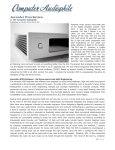
1.1. Introduction
This machine has been designed and manufactured to ensure the best possible
results in achieving the clarification of grape musts as rapidly as possible, while
enhancing the qualities of the end product. The machine is so user-friendly,
practical and versatile that it is suitable for use in any wine cellar and will be
bound to satisfy a variety of needs.
When using and servicing the machine, always comply scrupulously with the
contents of this booklet, which should be read carefully before taking any action
to install, use or service the equipment.
It is essential to complete these procedures properly and to monitor the product
entering and leaving the machine in order for it to satisfy your needs and ensure
an excellent performance.
Before taking any action on the machine, it is essential to make sure that
operators are capable of completing all the procedures described in this
manual and that they know how to repeat them as and when necessary.
Always keep the user manual readily available when taking action on the
machine.
Special attention must be paid to the safety recommendations concerning
the use of the machine. A proper understanding of and compliance with
these recommendations is fundamental to operator safety.
The manufacturer accepts no liability for any damage caused directly or
indirectly to persons or property as a result of failure to comply with the
recommendations in this user manual.
1.2. Considerations on the instructions
Due to the numerous variables that can affect the grape must clarifying process,
it is extremely difficult to provide unequivocal recommendations on the best way
to complete the various procedures. However, once you have gained a little
experience of using the machine, it will soon become evident that its great
potential for satisfying your every need in use with a variety of products.
a) This manual contains instructions for the standard version of the equipment
and it may be that the machine in your possession does not include some of
the components illustrated here, or that said components are arranged
differently from those described in the manual, without this affecting the
efficiency and performance of the equipment in any way
b) When working with the machine, carefully follow the instructions concerning
the operation of the valves and taps.
Operating errors or taking action other than as specified in this manual may
have undesirable effects on the end product.
Eco-Flot_0408R02EN
3
1.3. General safety recommendations
y It is forbidden for any unauthorized personnel to use the machine.
y It is forbidden for any persons under the influence of drugs, alcohol or
medication affecting the speed of their reactions to assemble, commission,
control, service or dismantle the machine.
y Only use the machine in safe operating conditions.
y Only use the machine for its intended purpose. Any other or improper use
cannot assure adequate safety.
y It is strictly forbidden for a person from outside or without authorization to
come into the vicinity of the machine when it is functioning.
y It is forbidden for anyone to take independent action or perform maneuvers
other than those for which they have been authorized, or that may affect their
own or other people's safety.
y It is compulsory for the operator to immediately deal with or report any
damage or changes to machine parts that may influence its safety.
y Never dismantle, modify or disable parts of the machine (functional parts,
control systems or safety devices).
y In the workplace, it is forbidden to use clothes or personal belongings that,
given the nature of the process and the characteristics of the machine, might
constitute a hazard for personal safety. Personal clothing worn at the
workplace must consequently have no loose parts that may be drawn in by
any moving parts.
y Never wear bracelets, necklaces or other objects that may become caught up
in moving parts.
y Always use clothing and personal protective equipment as specified in this
manual and in the safety standards adopted at the plant.
y The personnel authorized to take action on the machine must use only the
equipment provided and appropriate tools (in good working order) for any
servicing work they undertake; the specified methods must be scrupulously
and constantly followed.
y While at work, personnel must remain in the right position and always avoid
exposing themselves to any risk.
y Workstations must be kept clean and tidy; all waste of any kind must be
placed in suitable containers.
y It is forbidden to take any steps other than as specified in this manual or
without first making the machine safe.
y The responsibilities for the assembly, dismantling and reassembly,
commissioning and servicing of the machine must be clearly defined and
scrupulously followed.
y Never aim jets of water at the electrical parts of the machine.
y In the event of fire, use dry extinguishers to avoid spreading the flames
further.
y In the event of an emergency, every worker must contribute - according to
their respective abilities, experience and aptitude – to helping the people
appointed to undertake fire prevention, fire-fighting, evacuation, safety and
first aid measures.
4
Eco-Flot_0408R02EN
y Any work on the electrical equipment must be handled exclusively by a
qualified electrician.
1.4. General description
Clarifying a grape must prior to its fermentation is a fundamental step in order to
obtain wines with the best possible sensory features.
Eliminating the solid particles from the grape must restricts higher alcohol
production during the fermentation process and increases the concentrations of
esters, consequently enhancing the wine’s aroma and generally improving its
quality.
In some cases, clarifying agents (e.g. bentonite, gelatin, silica gel, casein and
activated carbon) are used to facilitate and speed up the separation of the solid
particles from the grape must, and to reduce its colloid content. All these
clarifying adjuvants bind electrically to the solids and colloids, giving rise to a
flocculation process.
Clarifying by flotation involves injecting tiny bubbles of gas into the lower portion
of the grape must to clarify. As the gas spreads through the fluid, it tends to rise
to the surface, entraining the flakes contained in the must.
A compact layer of these solid particles progressively forms on the surface of the
product and the clarified fluid can then simply be drawn off from the lower part of
the tank.
In other words, when the machine receives the must to treat from a feed tank, it
saturates the fluid with tiny gas bubbles - sometimes with an added clarifying
agent - and then returns the must to the same tank where the separation
process can begin.
The Eco-Flot machines are all similar from the functional and structural
standpoint, the only substantial difference between them being the hourly output
of treated product obtainable.
Where necessary, at the customer's request, the machines can be delivered for a
powering at a frequency of 50 or 60 Hz.
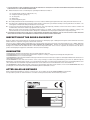
1.5. Machine identification
The machine is identified by means of a nameplate located as shown in the
figure.
Eco-Flot_0408R02EN
5
This nameplate must remain intact and clearly legible because it specifies the
main characteristics of the machine, i.e.
-
the manufacturer's name and address;
the name of the machine;
the serial number;
the year of construction;
the weight.
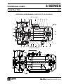
1.6. Description of the machine
The Eco-Flot is a compact trolley-mounted unit comprising a centrifugal pump
for circulating the must, a unit for delivering the gas (air or nitrogen) and
adjusting its flow rate, means for measuring the flow rate of the gas, a valve for
delivering flocculation adjuvant and other valves and pressure gauges for
adjusting and monitoring the working pressures and flow rates (see figure).
6
1)
Intake valve; connect the piping for delivering the product to treat.
2)
Adjuvant intake valve; connect the piping, if any, for delivering a flocculation
adjuvant (liquid or emulsion). By adjusting this valve with the pump running,
you can then add the adjuvant to the product being treated.
3)
Counter pressure gauge
4)
Valve for adjusting the treated product delivery rate; connect the piping for
discharging the treated product into the tank.
Eco-Flot_0408R02EN
5)
Venting tap and sample collector
6)
Saturation pressure gauge
7)
Centrifugal pump
8)
Compressed air or nitrogen delivery and flow adjustment unit; turn the
handle clockwise to increase the pressure or anticlockwise to reduce it.
9)
General on/off switch.
10) Gas flow meter; turn the knob anticlockwise to open the gas flow and adjust
the flow rate, which is indicated by the ball sliding inside a graduated
channel.
11) Trolley complete with wheels
12) Saturation gas tank
13) Check valve on the compressed air or nitrogen supply line
1.7. Intended use
The Eco-Flot is for use in the flotation of white and rosé grape must at ambient
temperatures.
In addition to the flotation of grape must, the Eco-Flot is also suitable for use as
a normal transfer pump for use with wines and liquid foodstuffs.
Eco-Flot_0408R02EN
7
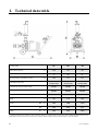
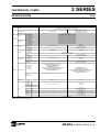
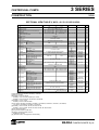
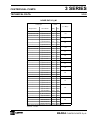
2. Technical data table
Eco-Flot model
S1
S2
S3
Rated capacity at 6 bar
m3/h
13.5
29
42
Mean capacity at 5.5 bar
m3/h
17
33
51
Gas (air/nitrogen) consumption at 7 bar
m3/h
0.8
1.6
2.5
Ebara
32-200/5.5kW
Ebara
40-200/11kW
Ebara
50-200/15kW
Connectors at inlet for product to treat
DN 50
DN 80
DN 80
Connectors at outlet for treated product
DN 50
DN 65
DN 65
dB(A)
75
80
80
kg
80
110
140
Centrifugal pump model
Sound pressure level**
Weight
Length*
A
mm
1215
1330
1370
Width*
B
mm
530
530
530
Height*
C
mm
1215
1215
1220
* Dati indicativi/Indicative data/Änderungen vorbeachten/Données indicatives
** Livello di pressione sonora media ad 1 metro di distanza / Mean sound pressure level at a distance of 1meter / Mittlerer Schalldruckpegel auf einem
Meter Distanz / Niveau de pression sonore moyenne à 1 mètre de distance / Nivel de presión acústica mediana a 1 metro de distancia.
8
Eco-Flot_0408R02EN
3. Installation instructions
Prior to delivery, the machine undergoes careful testing and inspection under
various working conditions in order to guarantee its smooth operation.
The following recommendations should be followed, however, to ensure its
proper, safe installation.
3.1. Lifting and moving the machine
DANGER
Before unloading the machine, make sure that the surface on which it is
to stand is capable of supporting its weight.
The floor where the machine is used should have a load-bearing
capacity corresponding to the combined weight of the machine and its
contents. See the Specifications Table for details.
Also ensure that the means used to unload and move the machine are
of suitable load-bearing capacity.
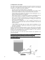
To lift and handle the machine in transit, use belts and a crane.
Take care to ensure that the belts do not come to bear on plastic or other
deformable parts, or electric cables.
To lift the machine, proceed as shown in Figure 1
brake on wheel
Figure 1
Once it is on the floor, the machine is easy to move because it is mounted on
wheels.
IMPORTANT
Once the machine has been positioned in the work place and before it is used,
make absolutely sure that it is perfectly stable and that the blocking device
(brake on wheel) is enabled.
Eco-Flot_0408R02EN
9
3.2. Hydraulic connections
The machine must be suitably connected to the tank from where it receives and
into where it discharges the product being treated, as well as to the optional
connection for a supply of flocculation adjuvant.
-
The pipes used may be flexible (plastic) or rigid (steel).
Rigid connection pipes should be secured separately from the filter in order
to prevent their weight from resting on the inlet and outlet connections.
-
Provide flexible joints between the machine and any rigid pipes so as to
avoid any mutual transmission of vibrations.
-
Pipes should conform to all requirements concerning compatibility with the
product being treated (e.g. suitable for foodstuffs or corrosive liquids).
-
Pipes must be capable of withstanding the mechanical stress produced by
the machine, e.g. they should not be prone to crushing as a result of the
suction force of the feed pump.
-
They should be of suitable size, i.e. with a diameter proportional to the
capacity of the machine and never less than the diameter of the inlet and
outlet connections.
-
If both flexible and rigid pipes are used, check the tightness of the
connections frequently to prevent the machine from sucking in air through
any loose connections.
Connect the piping delivering the product to treat to the Eco-Flot to the partial
drainage valve on its must tank and the piping for discharging the clarified
product to the total drainage valve; the adjuvant supply line, if any, should be
connected to the valve 2 (see figure below).
The sizes and types of the inlet and outlet connectors are specified in the
technical data table.
To ensure the proper operation of the machine, the suction piping should be
kept as short as possible, preferably no more than 3 meters long.
The delivery piping should also be kept as short as possible, and preferably no
more than 3 meters long.
ADJUVANT
10
Eco-Flot_0408R02EN
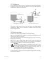
3.3. Preliminaries
For the machine to function properly, it is essential for the level of the product
contained in the tank to be higher than the axis of the pump (FEED UNDER A
HYDROSTATIC HEAD (see figure below).
PUMP AXIS
LEVEL OF PRODUCT
LEVEL OF PRODUCT
FULL PIPE
PUMP AXIS
FEED UNDER HYDRSTATIC HEAD
FEED ABOVE HYDROSTATIC HEAD
If the level of the product is lower than the pump’s axis (FEED ABOVE
HYDROSTATIC HEAD), then it is essential to completely fill the suction piping
before starting the pump.
3.4. Electric connections
All the Eco-Flot machines are powered by a three-phase voltage.
Make sure the power supply available at the plant provides electricity with
characteristics suited to the machine.
The machine is connected to the mains power supply by means of a factoryfitted power cord and plug.
Make sure, or have an expert check, that the power socket from which the
machine is powered is complete with fuses or an automatic thermomagnetic
circuit breaker with a capacity no higher than that of the machine.
DANGER
As in the case of any ordinary or extraordinary action taken on the
machine’s electrical system, the mains connection should be handled
by a qualified TECHNICIAN and the mains line should conform to
current standards (CEI, etc.) and existing legislation.
Bear in mind that it is compulsory to earth the machine.
It is also essential to comply with all safety regulations regarding the room where
the machine is installed.
Eco-Flot_0408R02EN
11
3.5. Checking the cyclic sense of the power phases
After connecting the machine to the mains power supply and before starting to
use it, check whether the wiring of the power supply phases has been done
correctly.
IMPORTANT
The pump must never be allowed to run dry.
The mechanical seal may be damaged if the pump is allowed to
function, even briefly, without any fluid inside it.
Close the valve 2, open the inlet valve 1 and the outlet valve 4 and wait for a few
seconds to allow for the grape must to fill the piping in the circuit and the
centrifugal pump. While the circuit is filling, vent the air from inside the system
through the sample collector tap 5 and only close this tap again when grape
must begins to come out.
Start the centrifugal pump in short pulses by turning the on/off switch 9 briefly to
position 1 and make sure that the motor turns in the right direction, generally
indicated by a red arrow on the pump.
MAIN ON/OFF SWITCH
If the motor is not turning in the right direction, you will need to invert the
position of the wiring connecting the machine to the mains power supply.
3.6. Checking the phase balance
Do not operate electric motors if the voltage unbalance between the phases is
greater than 3%.
Use the following formula to check the balance:
max. voltage shift from mean
% voltage unbalance =
mean voltage
X 100
A
B
Example: rated mains voltage 400V 3 ~ 50 Hz
AB = 409V
BC = 398V
AC = 396V
mean voltage =
12
409 + 398 + 396
3
= 401V
Eco-Flot_0408R02EN
C
How to calculate the percentage of unbalance:
% voltage unbalance =
409 – 401
x 100 = 1.99%
This value is acceptable because it is less than the maximum allowable, i.e. 3%.
IMPORTANT
If the mains voltage has an unbalance greater than 3%, contact the Electricity
Board. Operating the machine with a voltage unbalance between the phases
greater than 3% makes the GUARANTEE NULL AND VOID.
The mains power supply must coincide with the rated value ± 10%.
3.7. Connection to the pneumatic system
The Eco-Flot needs to be connected to a supply of compressed air or nitrogen
at a pressure of approximately 7 bar.
The gas supply, from bottles or generators, is connected to the coupling on the
unit 8.
If you use compressed air coming from your own generators (compressors), it is
always a good idea to install specific air filters (not included in the supply).
DANGER
In some stages of normal use, the machine is under pressure.
Never open the machine or remove any machine components before
this pressure has been completely vented.
Eco-Flot_0408R02EN
13
4. Use
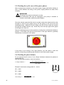
4.1. Start-up
Make sure the level of the product contained inside the tank is sufficient to leave
at least 40-50 cm of empty space above it to allow for the cap of solid particles to
form on the surface of the grape must, otherwise it becomes necessary to
routinely draw off the cap with the aid of a piston pump (not included in the
supply).
Cap suction pump
CAP
MUST
CAP
MUST
Make sure the product has been treated with a pectolytic enzyme preparation,
according to the doses and timing recommended by the manufacturer, so as to
achieve a perfect rupture of the pectins.
Make sure the valve 2 has been closed and the inlet and outlet valves 1 and 4
have been opened properly. Wait a few seconds for the grape must to fill the
piping in the circuit and the centrifugal pump.
During this filling procedure, vent off the air from inside the circuit through the
sample collector tap 5, closing it again as soon as the must begins to come out.
Check the supply of compressed air or nitrogen to the unit 8 and adjust the
pressure to 7 bar.
If you wish to use a flocculation adjuvant, prepare the mixture in a small tank and
immerse a suction pipe connected to the valve 2 in the tank, leaving the valve
closed.
Close the outlet valve 4.
Start the centrifugal pump by turning the main switch to position 1 and slowly
open the outlet valve 4.
If you have chosen to add an adjuvant to the must, slowly open the valve 2 and,
if necessary, slightly close the must inlet valve 1 if you notice any adjuvant
uptake problems. During the suction phase, make sure that the gas supply is
cut off and that the outlet valve 4 is adjusted so as to obtain a pressure of 4 bar
on the pressure gauge 6. The must is mixed with the adjuvant during this
recirculation phase.
When all the adjuvant has been added, you can begin to treat the product with
the gas (air or nitrogen).
14
Eco-Flot_0408R02EN
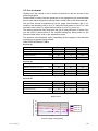
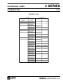
4.2. Gas treatment
Slightly close the valve 4 so as to obtain a pressure of 6 bar (as shown on the
pressure gauge 6).
Double check to ensure that the pressures on the gauges are as recommended
above, then adjust the gas flow rate by means of the knob on the flow meter 10.
The gas flow should be adjusted to suit the grape must saturation rate; if, for
instance, the saturation rate is 10 m3/h, adjust the flow meter to 0.25 m3/h; if the
saturation rate is 20 m3/h, adjust the flow meter to 0,5 m3/h; and so on.
The working pressures may drop while the gas is being delivered, in which case
you will need to restore them to the required settings by taking action on the
inlet and outlet valves, and on the adjustment knobs.
The duration of the treatment varies, depending on the capacity of the machine
and the type of product being treated.
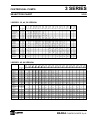
INDICATIVE REFERENCE TABLE
Eco-Flot S1
Example of volume for flotation
hl
100
100
100
Minimum pumping over time
min.
30
35
45
Pressure reading on gauge 6
bar
5.0
5.5
6.0
Product flow rate
3
m /h
20
17
13,5
Gas flow rate
m /h
0,5
0,42
0.34
hl
200
200
200
Minimum pumping over time
min.
30
35
40
Pressure reading on gauge 6
bar
5.0
5.5
6.0
Product flow rate
3
m /h
38
33
29
Gas flow rate
m /h
0,95
0,82
0,72
hl
300
300
300
Minimum pumping over time
min.
32
35
43
Pressure reading on gauge 6
bar
5.0
5.5
6.0
Product flow rate
m3/h
56
51
42
Gas flow rate
m /h
1,4
1,27
1,05
3
Eco-Flot S2
Example of volume for flotation
3
Eco-Flot S3
Example of volume for flotation
3
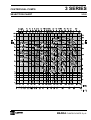
Product flow rate [m3/h]
Output curves
80
70
60
50
40
30
20
10
0
EcoFlot S1
EcoFlot S2
EcoFlot S3
5,0
5,5
6,0
Pressure gauge reading 6 [bar]
Eco-Flot_0408R02EN
15
Monitor the efficiency of the clarification process by collecting a sample of
product in a glass container from the tap 5. If the process is going smoothly,
there should be a visible separation of the lees.
When the treatment has been completed, close the gas supply, switch off the
machine, close the inlet and outlet valves 1 and 4, vent off the residual pressure
through the tap 5 and disconnect the piping.
4.3. Lees separation
The phase in which the lees are separated from the grape must demands no
action or monitoring on the part of the operator. This phase consists of the
interval during which the gas bubbles rise to the surface, carrying the lees with
them and forming the cap on top of the must.
How long this interval lasts depends on the height of the tank. It is generally
assumed that you should allow an hour for each meter of the tank’s height.
You can also wait for less than the above-suggested interval, in which case the
lees will be less concentrated; waiting a longer time will increase the
concentration of the lees without posing any risk of the cap dropping back into
the must (providing the fermentation process has not begun in the meantime).
4.4. Transfer
Once the separation phase has been completed, you can draw off the clarified
mast. To do so, first attach a sight glass on the valve for completely draining the
tank.
Because the flotated solids will have risen to the top of the tank, you simply need
to draw off the clarified must through the total drainage valve up until the sight
glass shows the first signs of the passage of the flotated solids.
Then close the valve, change the piping and discharge the lees into a separate
collection tank.
16
Eco-Flot_0408R02EN
5. Cleaning and servicing
To keep the machine in perfect and efficient working order, you need to perform
a few simple cleaning and servicing procedures.
DANGER
Pay the utmost attention when cleaning the machine manually with the
aid of liquids. Always disconnect the pump from the mains power
supply before aiming jets of water at any part of the machine.
1) At the end of each treatment cycle, or when the machine’s performance
deteriorates, you need to clean the machine, the piping and the tanks
thoroughly with clean water at approximately 30°C/86°F, possibly adding
some citric acid. Run the machine and allow the solution to circulate for 1015 minutes in order to eliminate all traces of solid residues.
2) If the pump becomes severely clogged, run a counterflow washing cycle,
sending water under high pressure through the valve 4.
3) Before setting the machine aside for any lengthy period of time, disconnect
the electric power supply and completely empty any residual liquids from the
machine by unscrewing the knob situated on the underside of the pump.
6. Troubleshooting
This section deals with certain anomalies that may be encountered during the
normal use of the machine.
DANGER
When taking any action on the machine, always comply with the
previously-mentioned safety recommendations.
Do not take any action other than as envisaged in this user manual.
All action must be undertaken exclusively by specialized, suitablyqualified personnel (INSTALLERS, OPERATORS, ENGINEERS, etc).
1. THE WORKING PRESSURE FAILS TO BUILD UP
-
Make sure the pump is turning in the right direction.
-
Make sure there is no air in the circuit and, if necessary, vent off any air
through the tap 5.
-
Clean the piping and the machine as explained in section 4, item 1, because
it may have become clogged.
-
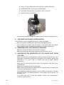
Make sure the filter in the gas supply unit 8 has not become clogged; to do
so:
•
•
Eco-Flot_0408R02EN
disconnect the compressed air supply;
turn the container 1 anticlockwise (see figure below) and remove it;
17
•
•
•
•
-
empty out any condensation and wash the container with water;
dismantle the filter 2 by turning it anticlockwise;
accurately clean the filter 2 or replace it with a new one;
reinstall all the components.
If the problem persists, contact the manufacturer’s customer support service.
2. THE PUMP’S EFFICIENCY DETERIORATES.
The pump has become clogged with skins or other solid matter.
- Run a counterflow washing cycle with water under high pressure.
- Avoid sucking the product from the bottom of the tanks when the product
being treated contains considerable quantities of solids in suspension.
3. PROBLEMS WITH THE UPTAKE OF ADJUVANT
-
Make sure the suction pipe has not become clogged.
Reduce the working pressure by slightly closing the intake valve 1.
4. UNSATISFACTORY SEPARATION OF THE GRAPE MUST FROM
THE LEES
-
-
-
18
Make sure that all the recommended working pressures and gas flow rates
have been scrupulously maintained throughout the treatment (during the
treatment, it is a good idea to monitor and restore these working
parameters).
Make sure the specified treatment times and separation time have been
complied with.
Make sure the grape must is not fermenting.
Make sure the must has been treated with the right quantity of enzymes and
for the time specified by the supplier.
The temperature of the must may be too low, making it necessary to increase
the gas flow rate. The ideal temperature of the grape must is around 1825°C/64.4-77°F.
If all these tests fail to solve the problem, contact the manufacturer’s
customer support service.
Eco-Flot_0408R02EN
ELETTROPOMPE EBARA
Manuale d’uso e manutenzione (Parte 1 di 2) .....................................................................2
EBARA MOTOR-DRIVEN PUMPS
User’s Maintenance Manual (Part 1 of 2) .............................................................................6
ÉLECTROPOMPES EBARA
Manuel d’utilisation et d’entretien (1e partie de 2) ........................................................... 10
EBARA-ELEKTROPUMPEN
Gebrauchs- und Instandhaltungshandbuch (Teil 1 von 2) ................................................ 14
BOMBAS ELÉCTRICAS EBARA
Manual de uso y mantenimiento (Primera parte de dos) ................................................. 18
ELPUMPAR EBARA
Instruktionsbok för drift och underhåll (del 1 av 2) ........................................................... 22
ELEKTROPUMPEN EBARA
Brugs- og vedligeholdelsesanvisninger (Afsnit 1 af 2)....................................................... 26
EBARA-SÄHKÖPUMPUT
Käyttö- ja huolto-ohje (osa 1/2) .......................................................................................... 30
EBARA ELEKTRISCHE POMPEN
Handleiding voor gebruik en onderhoud (Deel 1 van 2) ................................................... 34
ELETROBOMBA EBARA
Manual para o uso e manutenção [parte 1 de 2] ............................................................. 38
(M
1 2) ............................................................ 42
ELEKTROERPADLA EBARA
Návod k použití a údržb (ást 1. z 2) ................................................................................ 46
POVRCHOVÉ ELEKTRICKÉ ERPADLÁ
Návod na použitie a údržbu (as 1. z 2) ........................................................................... 50
ELEKTROPOMPY EBARA
Instrukcja uytkowania i konserwacji (Cz 1 z 2) ........................................................... 54
EBARA
!"#"$%&#" '" *!%'+,&,799 9 &:;"<%+=9#,>9? (@,%&E 1 9F 2) ................................. 58
EBARA ELEKTRO POMPALARI
KullanJm ve bakJm kJlavuzu (2 kJsmJn 1. kJsmJ)................................................................. 62
69
Δ....................................................................................................................................
˯ΰΟ
ΔϧΎϴμϟϭϝΎϤόΘγϼϟΕΎϤϴϠ˰όΘϟΏΎΘϛ
I
GB
F
D
E
S
DK
FIN
NL
P
GR
CZ
SK
PL
RU
T
INSTRUCTION MANUAL REGARDING USE AND MAINTENANCE
PART 1
TO BE KEPT BY THE USER
1. INTRODUCTION
GB
This instruction manual is made up of two parts: PART 1 which
contains general information regarding all our production and
PART 2 which contains speciWc information regarding the motor-driven pump that you have purchased. The two booklets are
complementary to each other, therefore make sure that you
have both of them.
Follow the instructions given in these booklets in order to obtain
optimum return and operation from your motor-driven pump. If
any other information is necessary, please contact the nearest
authorised retailer.
If the booklets contain contrasting information, keep to what is
indicated in PART 2 (product speciWcations).
THE REPRODUCTION, EVEN PARTIAL, OF THE ILLUSTRATIONS
AND/OR TEXT HEREIN IS FORBIDDEN.
The following symbols are used throughout the instruction
booklets:
WARNING!
Risk of damaging the pump or the system
Risk of injuring people or damaging things
Risks of an electrical nature
2. CONTENTS
1.
2.
3.
4.
5.
6.
7.
8.
9.
10.
11.
12.
13.
INTRODUCTION
page 6
CONTENTS
page 6
MANUFACTURER IDENTIFICATION DATA
page 6
GUARANTEE AND TECHNICAL ASSISTANCE
page 6
GENERAL SAFETY WARNINGS
page 6
TECHNICAL-PRODUCTION CHARACTERISTICS
page 7
INSTALLATION, DISMANTLING AND TRANSPORTATION page 7
ELECTRICAL CONNECTION
page 7
USE AND STARTING
page 8
MAINTENANCE AND REPAIRS
page 8
DISPOSAL
page 9
SUPPLIED TECHNICAL DOCUMENTATION
page 9
DECLARATION OF CONFORMITY
page 73
3. MANUFACTURER IDENTIFICATION DATA
3.1. MANUFACTURER DATA
EBARA PUMPS EUROPE S.p.A.
Plant management:
Via Pacinotti, 32 - 36040 BRENDOLA (VI) ITALY
Telephone: 0444/706811 - Telefax: 0444/706950 - Telex: 480536
Registered ofce:
Via Campo Sportivo, 30 - 38023 CLES (TN) ITALY
Telephone: 0463/660411 - Telefax: 0463/422782
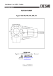
3.2. MOTOR-DRIVEN PUMPS
See plates
in FIG. 6:
6.1 for motor-driven surface pumps
Once you have received the motor-driven pump, make sure that
the packaging is not broken or seriously damaged. If it is, immediately inform the person who delivered it. After extracting
the motor pump from its packaging, make sure that it was not
damaged during transportation. If it has been, inform the retailer within 8 days from delivery. Check the motor-driven pump
plate to ensure that the indicated characteristics are those requested by you.
The following parts, being normally subject to wear, have a limited guarantee:
• bearings
• mechanical seals
• grommets
• capacitors
If a fault that is not listed in the “TROUBLESHOOTING” table
(chapter 10.1.) occurs, please contact the nearest authorised
retailer.
5. GENERAL SAFETY WARNINGS
Before starting the motor-driven pump, the user must follow the
operations indicated in this manual (PART 1 and PART 2), and
apply them each time the motor-driven pump is used or when
maintenance is carried out on it.
5.1. PREVENTIVE MEASURES TO BE TAKEN BY THE USER
Users must observe the accident prevention regulations
that are in force in their countries at the time. They must
also pay attention to the motor-driven pump characteristics
(see “TECHNICAL DATA” in PART 2).
While repairing or carrying out maintenance on the motor-driven pump, disconnect the electric supply. Doing this
avoids accidental starting, which could injure people and/or
cause damage.
Any maintenance, installation or handling carried out on the
motor-driven pump while it is still being powered can seriously injure, or even kill, people.
When starting the motor-driven pump, users must ensure
that their feet are not bare or, worse, immersed in water.
They must also ensure that their hands are not wet.
Users must not operate or carry out any work on the motordriven pump that is not permitted in this manual.
5.2. IMPORTANT PROTECTIONS AND CAUTIONS
All motor-driven pumps are designed in such a way that all
moving parts are made safe by using guards. The manufacturer declines any responsibility in the event of damages
caused by the removal of said protections.
Each conductor or powered part is electrically insulated with
regards to earth. Extra security is also added by connecting
the accessible conducting parts to an earth conductor. This
ensures that accessible parts cannot become dangerous
should the main insulation become faulty.
6.2 for submersible motor-driven pumps
For product type, see PART 2.
4. GUARANTEE AND TECHNICAL ASSISTANCE
THE GUARANTEE IS RENDERED NULL AND VOID IF THE INSTRUCTIONS GIVEN IN THIS BOOKLET ARE NOT ADHERED TO
6
AND/OR IF ANYONE OTHER THAN PERSONNEL FROM OUR
HELP CENTRES INTERVENES ON THE MOTOR-DRIVEN PUMP.
IN THESE CASES, THE MANUFACTURER IS RELIEVED FROM
ALL RESPONSIBILITY REGARDING INJURY TO PEOPLE AND
SUBSEQUENT DAMAGE TO ADJACENT ITEMS AND/OR THE MOTOR-DRIVEN PUMP ITSELF.
5.3. RESIDUAL RISKS FOR SURFACE PUMPS
The only residual risk is the possibility of coming into contact
(even if not accidentally) with the motor cooling fan by inserting thin objects (i.e. screwdrivers, small sticks, etc.) through the
holes of the fan cover.
6. TECHNICAL-PRODUCTION CHARACTERISTICS
The motor-driven pump you have purchased has been designed
and manufactured in compliance with the following directives:
• MECHANICAL RISKS (Enclosure I Machines Directive):
- EN 292-1 and EN 292-2
• ELECTRICAL RISKS (Enclosure I Machines Directive):
- EN 292-1 and EN 292-2
- CEI EN 60204-1
• VARIOUS RISKS (Enclosure I Machines Directive):
- 2006/42/CE – Enclosure I
The electrical components and relative circuits installed on the
motor-driven pumps are in accordance with the CEI EN 602041 Directive.
7.4. TRANSPORTATION
The motor-driven pump is packed in a carton or can be Wxed
to a wooden pallet, if pump weight and dimensions allow it.
Transportation should not, in any case, present any particular
problems.
Verify the total weight stamped on the box.
8. ELECTRICAL CONNECTION
ELECTRICAL CONNECTION MUST BE CARRIED OUT BY A
QUALIFIED ENGINEER.
IT IS ADVISABLE TO INSTALL A HIGH INTENSITY DIFFERENTIAL SWITCH (0.03 A) ON BOTH THE THREEPHASE AND
SINGLE PHASE VERSIONS.
WARNING!
7. INSTALLATION, DISMANTLING AND TRANSPORT
WARNING!
INSTALLATION MUST BE CARRIED OUT BY A
QUALIFIED ENGINEER.
7.1. GENERAL INSTALLATION PRECAUTIONS
a) Use metal or rigid plastic pipes in order to avoid their yielding
because of the depression created at suction;
b) support and align pipes so that they do not put any stress on
the pump;
c) avoid throttlings caused by bending suction and delivery
hoses;
d) seal any piping connections: air inWltration in the suction
pipe negatively affects pump operation;
e) we recommend that a non-return valve and a gate are installed on the delivery pipe at the motor-driven pump outlet;
f) Wx the piping to the reservoir or to any Wxed parts so that it is
not supported by the pump;
g) do not use a lot of bends (goosenecks) and valves;
h) on SURFACE PUMPS installed above head, the suction pipe
should be Wtted with a foot valve and Wlter in order to prevent foreign matter from entering and its end should be immersed at a depth that is at least twice the diameter of the
pipe; its distance from the bottom of the reservoir should
also be one and a half times its diameter.
For suctions longer than 4 metres use an oversized pipe
(1/4” wider at suction for improved efWciency).
7.2. INSTALLATION
a) Position the pump on a |at surface that is as close as possible to the water source. Leave enough space around the
pump to allow safe use and maintenance. A free space of
at least 100 mm must be kept in front of the cooling fan of
surface pumps in all cases;
b) lower submersible pumps using a rope Wxed to the handle
and hooks provided;
c) use pipes of suitable diameters (see PART 2) Wtted with
threaded sleeves that must be screwed onto the pump suction and delivery unions or its threaded counter|anges;
d) SURFACE PUMPS cannot be moved or used in the open except as stated in PART 2;
e) for speciWc instructions, consult the chapter “PREPARING
FOR USE” in PART 2.
7.3. DISMANTLING
The following must be done when moving or dismantling the
motor pump:
a) disconnect the electric supply;
b) remove the delivery and suction pipes (where present) if too
long or bulky;
c) if present, unscrew the screws that secure the motor-driven
pump to its supporting surface;
d) if present, hold the power cable;
e) lift the motor-driven pump using equipment suitable to the
pump weight and dimensions (refer to the plate).
GB
We recommend that power is supplied to the motor-driven pump using an electric panel equipped with switch,
fuses and a thermal switch calibrated to the current absorbed by the motor-driven pump.
The mains must be reliably earthed, according to the
electrical regulations in force in the user’s country: this is
the installer’s responsibility.
If the motor-driven pump is supplied without a power cable, use
a cable that complies with the regulations in force and the necessary section according to length, power and mains voltage.
If present, the plug of the single phase version must be
connected to the mains far from sprays, water jets or rain
and it must be accessible.
The three phase version does not have an internal motor
protector, therefore overload protection must be provided
by the user.
MOTOR-DRIVEN SURFACE PUMPS
WHILE CONNECTING, MAKE SURE THAT BOTH THE TERMINAL
BOARD AND THE MOTOR DO NOT GET WET.
– Connection of the single phase versions must be made on
the basis of whether thermoamperometric protection “P” is
internal (FIG. 1) or external (FIG. 2).
– For threephase versions, after connecting the star (FIG. 3) or
triangle (FIG. 4) cable to the terminal board, looking at the
pump from the motor side, check that the cooling fan turns
in the same way as the arrow on the label applied on the fan
cover. If it is incorrect, swap two of the three wires over on
the motor’s terminal strip.
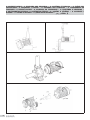
SUBMERSIBLE MOTOR-DRIVEN PUMPS
– In single phase versions, plug the unit into the socket.
– For threephase versions (FIG. 5), check that the motor turns
in a clockwise direction looking at the pump from the top,
proceed as follows: with the motor-driven pump not yet secured to the system, connect the power cable to the terminal board and switch on brie|y; the pump shall start with a
kick in an anti-clockwise direction, seen from the top of the
pump. If the direction is wrong (clockwise), invert two of the
three wires in the terminal board of the electrical panel.
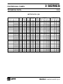
FIG. 7 shows the standard voltages shown on the plate with
their respective tolerances.
8.1. ADJUSTMENTS AND RECORDINGS
In pumps Wtted with a |oat, adjust the length of the |oat cable
with regards to the minimum and maximum value of the water
(see PART 2).
Check that the system automatisms do not require a number
of start-ups higher than the number shown in FIG. 8 for surface
pumps and in PART 2 for submersible pumps.
7
9. USE AND STARTING
NEVER ALLOW THE MOTOR-DRIVEN PUMP TO OPERATE WITHOUT WATER. DOING SO CAN SERIOUSLY DAMAGE THE INTERNAL COMPONENTS.
GB
9.1. GENERAL WARNINGS
a) Our surface pumps are designed to operate at a temperature
no higher than 40°C and a level no higher than 1000 metres;
b) our motor-driven pumps cannot be used in swimming pools or
similar plants;
c) prolonged motor pump operation with the delivery pipe closed
can cause damage;
d) avoid switching the motor pump on and off too frequently
(check the maximum number in FIG. 8);
e) during power cuts, it is advisable to disconnect the power to
the pump.
DISPLAYED FAULT
THE PUMP DOES
NOT WORK
The motor turns
9.2. STARTING
a) Start the pump two or three times to check system conditions;
b) restrict the delivery to cause a rapid pressure increase for a
few times;
c) make sure that the noise, vibration, pressure and electrical
voltage levels are normal.
9.3. STOPPING
a) Gradually interrupt water circulation in the delivery section to
avoid overpressure in the piping and pump caused by water
hammering;
b) switch off the main switch.
10. MAINTENANCE AND REPAIRS
We recommend periodically checking that the pump is working
correctly; pay particular attention to any abnormal noise or vibration and, for surface pumps, any mechanical seal leaks.
The main and most common special maintenance operations
are generally as follows:
} replacement of mechanical seals
} replacement of grommets
} replacement of bearings
} replacement of capacitors.
When the SURFACE pump remains inactive for a long period, it
should be emptied completely, removing the discharge and Wlling
caps, washed carefully with clean water then emptied. Do not
leave water deposits inside.
This operation must always be carried out whenever there is
a chance of frost in order to avoid the breakdown of the pump
components.
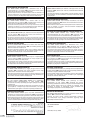
10.1. TROUBLESHOOTING
DISPLAYED FAULT
CAUSE
No electricity
Plug not inserted
THE PUMP DOES
NOT WORK
The motor does
not turn
Incorrect electrical
connection
Automatic switch
triggered or fuses
blown
Float sticking
Thermal protection
activated
(single phase)
8
SOLUTION
Check the
electrical
supply meter
Check the
connection to the
power supply
Check the terminal
board and the electrical panel
Reset the switch or
replace the fuses and
verify the cause
Check that the
|oat reaches the
level ON
It reactivates
automatically
(single phase only)
CAUSE
Decrease in the
line voltage
Wait for voltage to
return to normal
Suction Wlter /
hole blocked
Clean the
Wlter / hole
Foot valve
blocked
Clean the valve and
check its operation
Pump not
primed
Prime the pump
Check any delivery
non-return valves
Check the liquid
level
Pressure
too low
Restrict the
delivery gate
System
undersized
Re-examine
the system
Clean the piping,
valves, Wlters
Switch off the
pump or immerse
the foot valve
System dirty
THE PUMP
WORKS
with a reduced
ow rate
Water level
too low
Incorrect rotational Invert the two
direction
phases
(threephase only)
Supply the pump
Incorrect supply
with the voltage involtage
dicated on the ate
Leaks from piping
Check the joints
Pressure too high
Recheck the
system
THE PUMP STOPS
AFTER WORKING Liquid temperature
too high
FOR BRIEF
PERIODS
Thermal protection
Internal fault
intervention
THE PUMP STOPS
AFTER WORKING
FOR BRIEF PERIODS
Pressure
applications
The temperature
exceeds the
technical limits of
the pump
Contact the nearest
retailer
The difference
Increase the differbetween
ence between the
maximum and
minimum pressure two pressures
is minimal
THE PUMP DOES NOT
Maximum
STOP
pressure too high
Pressure applications
Flow rate too high
Cavitation
THE PUMP
VIBRATES
Or is too noisy
during operation
SOLUTION
Set maximum
pressure at a
lower value
Reduce the
|ow rate
Contact the nearest
retailer
Irregular piping
Fix in a better way
Noisy bearing
Contact the nearest
retailer
Foreign bodies
sliding along the
motor fan
Remove the foreign
bodies
Incorrect priming
Bleed the pump
and/or Wll it again
11. DISPOSAL
12. SUPPLIED TECHNICAL DOCUMENTATION
When disposing of the pump, please comply rigorously with the
regulations in force in your country, making sure that residues of
the treated liquid are not left inside the pump.
Most of our pumps do not contain hazardous polluting material.
SpeciWc cases are, however, indicated in the “DISPOSAL” chapter
in PART 2.
12.1. DRAWING SHOWING THE ELECTRICAL CONNECTIONS OF A
SINGLE PHASE MOTOR-DRIVEN PUMP
See FIG. 1-2
12.2. DRAWINGS SHOWING THE ELECTRICAL CONNECTIONS OF
A THREEPHASE PUMP
See FIG. 3-4-5
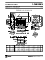
12.3. EXAMPLE OF A PLATE
See FIG. 6.1-6.2 (The manufacturer reserves the right to modify it).
FIG. 1
FIG. 2
GB
FIG. 3
FIG. 4
Y
Δ
FIG. 5
9
FIG. 6.1
FIG. 6.2
1)
“TYPE”
Modello pompa • Pump model • Modèle pompe • Pumpenmodell • Modelo bomba • Pumpens modell • Pumpemodel • Pumpun
malli • Model pomp • Modelo bomba • ~ • Model erpadla • Model erpadla • Model pompy • "$:+E >,%"%, •
Pompa modeli • ΔΨμϤϟϒϨλΝΫϮϤϧ
2)
“DATA
CODE”
Numero di serie • Serial number • Numéro de série • Seriennummer • Número de serie • Serienummer • Serienummer •
Sarjanumero • Serienummer • Numero de série •
•Výrobní íslo • íslo série • Numer fabryczny • :9> >":
• Seri numarasJ • ΔΨπϤϟϞδϠδΗϢϗέ
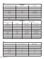
“Q”
Indicazione dei punti di portata minima e massima • Maximum and minimum |ow rate points • Indication des débits MINI et MAXI.
• Angabe des min. und des max. Durchsatzes • Indicación de los puntos de caudal mínimo y máximo • Indikation om punkter för
min. och max. kapacitet • Indikation om minimums- og maksimumskapacitetspunkterne • Minimi- ja maksimivirtausnopeuspisteet
• Indicatie minimum- en maximumdebiet • Indicações dos pontos de capacidade mínima e máxima • • Údaje o minimálním a maximálním dopravovaném množství • Údaje o minimálnom a maximálnom
dopravovanom množstve • Wskazanie punktów minimalnej i minimalnej nonoci • !,F,>9: &":! 9>9,+E>"
9 ,!%9,+E>"
Ϣ
'"9F#"$9&:+E>"%&9 • Minimum ve maksimum kapasite noktalarJ iareti • ΔΨπϤϟϪϴτόΗΔϴϤϛήΜϛϭϞϗϰϠϋϝΪΗ
“H”
Indicazione dei punti di prevalenza corrispondenti alla minima e massima portata • Head points corresponding to maximum and
minimum |ow rate • Indication des H.M.T. correspondant aux débits MINI et MAXI. • Angabe der Förderhöhe, die dem min. und dem
max. Durchsatz entsprechen • Indicación de los puntos de presión correspondientes a los caudales mínimo y máximo • Indikation
om uppfordringshöjdspunkter som motsvarar min. och max. kapacitet • Indikation om prævalenspunkterne, svarende til minimumsog maksimumskapaciteten • Minimi- ja maksimivirtausnopeutta vastaavat painekorkeuspisteet • Indicatie van de opvoerhoogte
overeenkomstig het minimum- en maximumdebiet • Indicações dos pontos de prevalência correspondentes á mínima e á máxima
capacidade • • 1.Údaje o dopravní výšce (výtlaku)
odpovídající minimálnímu a maximálnímu dopravovanému množství • Údaje o dopravnej výške (výtlaku) odpovedajúcej minimálnemu
a maximálnemu dopravovanému množstvu • Wskazanie punktów wysokiego cinienia odpowiadajcych minimalnego i maksymalnej
nonoci • !,F,>9: &":! >,'",, %""&#:&%&#?9; 9>9,+E>" 9 ,!%9,+E>" '"9F#"$9&:+E>"%&9 • Minimum ve
maksimum kapasite için basJnç yükseklii noktalarJ iareti • ΔϴϤϜϟϰϟΔΒδϨϟΎΑΔΨμϤϟϪϴτόΗωΎϔΗέήΜϛϭϞϗϰϠϋϝΪΗ
3)
4)
5)
“Hmax”
Prevalenza massima • Maximum head • Hauteur MAXI • Max. Förderhöhe • Presión máxima • Max. uppfordringshöjd •
Maksimum prævalens • Maksimipainekorkeus • Max. opvoerhoogte • Prevalência máxima • ~ • Maximální
dopravní výška • Maximálna dopravná výška • Cinienie maksymalne • ,!%9,+E> >,'" • Maksimum BasJnç Yükseklii •
ΔΨπϤϟϪϴτόΗωΎϔΗέήΜϛ
͉
6)
“V~”
Tensione/i nominale/i • Rated voltage/s • Tension/s nominale/s • Nennspannung/en • Tensión/es nominal/es • Märkspänning •
Nominalspænding • Nimellisjännite/-jännitteet • Nominale spanning(en) • Tensões / os nominais/ i • () () •
Jmenovité naptí • Menovité napätie • Napicie/a nominalne • ¡"9>,+E>": >,'¢=:>9: (>,'¢=:>9¢) • Nominal gerilim/ler •
VOLTϦ͉ϴόϤϟςγϮΘϤϟΪϬΠϟ
7)
“Hmin”
Prevalenza minima • Minimum head • Hauteur MINI • Min. Förderhöhe • Altura de elevación mínima • Min. uppfordringshöjd
• Minimum prævalens • Minimipainekorkeus • Minimale opvoerhoogte • Prevalência mínima • £ • Minimální
dopravní výška • Minimálna dopravná výška • Cinienie minimalne • 9>9,+E> >,'" • Minimum BasJnç Yükseklii •
ΔΨπϤϟϪϴτόΗωΎϔΗέϞϗ
͉
8)
9)
70
“P2”
Potenza nominale del motore (potenza resa all’asse) • Rated motor power (power delivered at axis) • Puissance nominale du moteur
(puissance rendue à l’axe) • Nennleistung des Motors (Leistungsabgabe an der Achse) • Potencia nominal del motor (potencia en el
eje) • Motorns märkeffekt (axeleffekt) • Motorens nominaleffekt (nytteeffekt på akslen) • Moottorin nimellisteho (akselin antoteho)
• Nominaal vermogen van de motor (vermogen overgebracht op as) • Potência nominal do motor [potência resistência eixo] • I
( ) • Jmenovitý výkon motoru (výkon v ose) • Menovitý výkon motora (meraný na osi) • Nominalna moc
silnika (moc na osi) • ¡"9>,+E>,¢ ">"%&E $#9¤,&:+¢ ("&$,#,:,¢ ">"%&E >, "%9) • Motorun nominal gücü (eksene verilen
güç) • έϮΤϤϟϲϓΔΠΗΎϨϟΓέΪϘϟρϭϮϠϴϜϟΎΑϦ͉ϴόϤϟϙήΤϤϟΓέΪϗ
“HP”
Potenza nominale del motore espressa in HP (horse power) • Rated motor power expressed in HP (horse power) • Puissance
nominale du moteur exprimée en HP (horse power) • Nennleistung des Motors, ausgedrückt in HP • Potencia nominal del motor en
HP (horse power) • Motorns märkeffekt i hästkrafter• Motorens nominaleffekt udtrykt i HP (hestekræfter) • Moottorin nimellisteho
hevosvoimina • Nominaal vermogen van de motor uitgedrukt in HP (“horse power”: paardekracht) • Potência nominal do motor
expressa em HP [ horse power] • ¥
¦ §P ( ) • Jmenovitý výkon motoru
vyjád¨ený v HP (ko©ská síla) • Menovitý výkon motora meraný v HP (horse power=konská sila) • Nominalna moc silnika wyraona
w koniach mechanicznych • ¡"9>,+E>,¢ ">"%&E $#9¤,&:+¢, #,=:>>,¢ # «.. (+"¬,$9>; %9+,;) • HP (beygir gücü) olarak
belirtilmi motorun nominal gücü • ϥΎμΤϟΎΑϙήΤϤϟΓέΪϗ
10) “Hz”
Frequenza • Frequency • Fréquence • Frequenz • Frecuencia • Frekvens • Frekvens • Taajuus • Frequentie • Frequência •
• Kmitoet • Frekvencia • Czstotliwo • @,%&"&, • Frekans • ΩΩήΘϟ
11) “A”
Corrente nominale • Rated current • Courant nominal • Nennstrom • Corriente nominal • Märkström • Nominalstrøm •
Nimellisvirta • Nominale stroom • Corrente nominal • • Jmenovitý elektrický proud • Menovitý prúd • Prd
nominalny • ¡"9>,+E> &"! • Nominal akJm • Ϧ͉ϴόϤϟέΎϴΘϟ
12) “P1”
Potenza assorbita dalla linea elettrica • Power absorbed by the electrical line • Puissance absorbée par la ligne électrique
• Leistungsaufnahme der elektrischen Leitung • Potencia absorbida por la línea eléctrica • Effektförbrukning • El-linjens
absorberede effekt • Ottoteho sähköverkosta • Geabsorbeerd vermogen door het elektriciteitsnet • Potência absorvida da linha
elétrica • ® ¥
• P¨íkon • Moc poch¯onita przez lini elektryczn • ">"%&E,
'"&:<+¢:,¢ "& *+:!&"%:&9 • Elektrik hattJ tarafJndan emilen güç • ˯ΎΑήϬϜϟϦϣΔΑϮΤδϤϟΓέΪϘϟ
13) “Phase”
Tipo di motore (monofase o trifase) • Motor type (single phase or threephase) • Type de moteur (monophasé ou triphasé)
• Motortyp (Einphasig oder Drehstrom) • Tipo de motor (monofásico o trifásico) • Motortyp (enfas eller trefas) • Motortype
(monofase eller trefase) • Moottorin tyyppi (yksi- tai kolmivaihe) • Motortype (éénfasig of driefasig) • Tipo de motor [monofásica ou
trifásica] • £ (¥ ¥) • Typ motoru (jednofázový nebo t¨ífázový) • Druh motora (jednofázový alebo
trojfázový) • Rodzaj silnika (jednofazowa lub trójfazowa) • ±9' $#9¤,&:+¢ ("$>"²,F> 9+9 &:;²,F>) • Motor tipi (mono faz
veya trifaz) • έϮτϟϲΛϼΛϭϱΩΎΣϙ˷ήΤϤϟωϮϧ
14) “min-1”
Velocità di rotazione • Rotational speed • Vitesse de rotation • Rotationsgeschwindigkeit • Velocidad de rotación •
Rotationshastighet • Rotationshastighed • Pyörimisnopeus • Rotatiesnelheid • Velocidade de rotação • T ¥ •
Rychlost otáení • Rýchlos otáok • Prdko obrotowa • !""%&E #,:>9¢ • Rotasyon hJzJ • ϥέϭΪϟΔϋήγ
Ϸ
15) ∇/m
Massima profondità di funzionamento • Maximum operating depth • Profondeur maximale de fonctionnement • Max. Einsatztiefe
• Máxima profundidad de funcionamiento • Maximalt driftdjup • Maksimal driftsdybde • Maksimikäyttösyvyys • Maximumdiepte
voor functionering • Máxima profundidade de funcionamento • ~ ³
• Maximální provozní hloubka •
Maximálna prevádzková h´bka • Maksymalna g¯boko dzia¯ania • ,!%9,+E>,¢ ¤+<9>, ,<"& • Maksimum çalJma derinlii
• ϞϴϐθΘϠϟήΜϛϷϭϰμϗϷϖϤόϟ
16) “F”
Capacità del condensatore (solo per monofase) • Capacitor capacity (single phase only) • Capacité du condensateur (seulement
pour monophasé) • Kapazität des Kondensators (nur für einphasige Version) • Capacidad del condensador (sólo monofásico) •
Kondensatorns kapacitet (endast enfas) • Kondensatorkapacitet (angår kun monofase) • Kondensaattorin kapasitanssin (vain
yksivaihe) • Condensorvermogen (alleen éénfasig) • Capacidade do condensador [somente para monofásica] • µ
( ¥ ) • Kapacita kondenzátoru (pouze u jednofázového erpadla) • Kapacita kondenzátora
(len pre jednofázu) • Pojemno kondensatora (jedynie dla jednofazowej) • ¶!"%&E !">$:>%,&", (&"+E!" $+¢ "$>"²,F>"¤") •
Kondansatör kapasitesi (sadece mono faz) • έϮτϟϱΩΎΣςϘϓϒΜϜϤϟΔόγ
17)
“Vc”
Tensione del condensatore (solo per monofase) • Capacitor voltage (single phase only) • Tension du condensateur (seulement
pour monophasé) • Spannung des Kondensators (nur für einphasige Version) • Tensión del condensador (sólo monofásico) •
Kondensatorns spänning (endast enfas) • Kondensatorspænding (angår kun monofase) • Kondensaattorin jännite (vain yksivaihe)
• Condensorspanning (alleen éénfasig) • Tensão do condensador [somente para monofásica] • ( ¥ ) • Naptí kondenzátoru (pouze u jednofázového erpadla) • Napätie kondenzátora (len pre jednofázu) •
Napicie kondensatora (jedynie dla jednofazowej) • ¡,'¢=:>9: !">$:>%,&", (&"+E!" $+¢ "$>"²,F>"¤") • Kondansatör gerilimi
(sadece mono faz) • έϮτϟϱΩΎΣςϘϓϒΜϜϤϟΪϬΟ
18) “IP”
Grado di protezione della pompa • Pump protection rating • Degré de protection de la pompe • Schutzgrad der Pumpe • Grado de
protección de la bomba • Elpumpens kapslingsklass • Pumpens beskyttelsesgrad • Pumpun suoja-aste • Beschermingsgraad van
de pomp • Grau de proteção da bomba • · • Stupe© ochrany erpadla • Stupe© ochrany erpadla •
Stopie¸ zabezpieczenia • ¹+,%% F,9& >,%"%, • Pompa koruma derecesi • ΔΨπϤϟΔϳΎϤΣϯϮΘδϣ
“Ins. C.
19) F S1”
Classe di isolamento motore e tipo di servizio • Motor insulation class and type of service • Classe d’isolation du moteur et type
de service • Isolierungsklasse des Motors und Betriebsart • Clase de aislamiento motor y tipo de servicio • Motorns isolation och
användningstyp • Motorens isolationsklasse og servicetype • Moottorin eristysluokka ja käyttötyyppi • Klasse motorisolatie en
type werking • Classe de isolamento motor e tipo de serviço •
• Stupe© izolace
motoru a typ použití• Trieda izolácie motora a typ použitia• Klasa izolacji silnika i rodzaju obs¯ugi • ¹+,%% 9F"+¢799 $#9¤,&:+¢ 9
&9' ,<"& • Motor izolasyon sJnJfJ ve hizmet tipi • ϞϤόϟωϮϧϭϙήΤϤϟϝΰϋΔΟέΩ
20) “ kg”
Peso • Weight • Poids • Gewicht • Peso • Vikt • Vægt • Paino • Gewicht • Peso • ·
• Hmotnos • Hmotnos • Ciar •
,%%, • AJrlJk • ϥίϮϟ
21) P/N°
Codice articolo pompa • Pump item code • Code article pompe • Artikelnummer der Pumpe • Código artículo bomba • Elpumpens
art. nr • Pumpeartikelkode • Pumpun tuotekoodi • Artikelcode pomp • Código artigo bomba • º • Kód výrobku
erpadla • Kód typu erpadla • Kod artyku¯u pompy • »&9!+ >,%"%, • Pompa ürün kodu • ΔΨπϤϟϢϗέ
71
FIG. 7
SINGLE PHASE
Voltage indicated in the label
Tolerance
Operative
110 [V]
± 6%
103 - 117 [V]
115 [V]
± 6%
108 - 122 [V]
220 [V]
± 6%
207 - 233 [V]
230 [V]
± 10%
207 - 253 [V]
240 [V]
± 6%
226 - 255 [V]
208-230 [V]
± 6%
196 - 244 [V]
220-230 [V]
± 6%
207 - 244 [V]
230-240 [V]
-10% +6%
207 - 255 [V]
Other [V]
± 5%
–
THREE PHASE
Operative Range
Voltage indicated in the
label
Tolerance
Delta connection “”
Star connection “Y”
220 ¿/ 380 Y [V]
± 6%
207 - 233 ¿
357 - 403 Y [V]
240 ¿/ 415 Y [V]
± 6%
226 - 253 ¿
390 - 440 Y [V]
230 ¿/ 400 Y [V]
± 10%
207 - 253 ¿
360 - 440 Y [V]
220-240 ¿/ 380-415 Y [V]
± 6%
207 - 253 ¿
360 - 440 Y [V]
230-240 ¿/ 400-415 Y [V]
-10% +6%
207 - 253 ¿
360 - 440 Y [V]
230 [V]
± 10%
207 - 253 ¿
not available
400 [V]
± 10%
not available
360 - 440 Y [V]
208 - 230 [V]
± 5%
198 - 242 ¿
not available
460 [V]
-10% +6%
not available
414 - 488 Y [V]
Other [V]
± 5%
–
–
FIG. 8
MAXIMUM NR OF STARTS PER HOUR
72
Nominal motor power (P2) [kW]
Closed couple pumps [N.°]
EVM, 3S, 3P [N.°]
À 1.85
40
35
2.2 ÷ 4
30
30
5.5 – 7.5
20
20
9.2 ÷ 13
15
15
15 – 18.5
12
15
22 – 30
12
12
37 – 45
/
8
55
/
4
PRODUCTS:
JES-JE- JESX-JEX- AGE-AGF-AGA-AGC; CD-2CD; CDX-2CDX-DWO-DWC-CMA-CMB-CMC-CMD-CMR-CDA; PRA; LPS; COMPACT-CVM-MATRIX-MULTIGO-MULTIGO INLINE; EVM; 3SERIES-MD; OPTIMA-BEST-RIGHT-DW; WINNER-BHS-IDROGO; SF6.
DICHIARAZIONE DI CONFORMITÀ
Noi, EBARA PUMPS EUROPE S.p.A., dichiariamo sotto la nostra
responsabilità che i ns. prodotti sono in conformità alla Direttiva
Macchine 2006/42/CE, alla Direttiva Bassa Tensione 73/23/
CEE come modiWcato dalla direttiva 93/68/CEE e alla Direttiva
Compatibilità Elettromagnetica 89/336/CEE come modiWcato
dalla direttiva 93/68 CEE.
ERKLÆRING OEM OVERENSSTEMMELSE
Vi, EBARA PUMPS EUROPE S.p.A., erklarer herved ifølge
vort ansvar, at vore produkter er i overensstemmelse med
Maskindirektiv 2006/42/CE, med Lavspændingsdirektiv
73/23/CEE som modiWcerets fra direktiv 93/68/CEE og med
Direktivet for Elektromagnetisk Kompatibilitat 89/336/CEE som
modiWcerets fra direktiv 93/68/CEE.
DECLARATION OF CONFORMITY
We, EBARA PUMPS EUROPE S.p.A., declare under our own
responsibility that our products conform to the Machinery
Directive 2006/42/EC, to the Low Voltage Directive 73/23/EEC,
as amended by Directive 93/68/EEC and to the Electromagnetic
Compatibility Directive 89/336/EEC as amended by Directive
93/68/EEC.
YHTÄPITÄVYYSLAUSUNTO
Me, EBARA PUMPS EUROPE S.p.A., ilmoitamme vastuunalaisena,
että tuotteemme ovat yhdenmukaisia Kone Ohjeiden 2006/42/
CE, Matalajännite Ohjeiden 73/23/CEE muutettu säännöksillä
93/68/CEE ja Sähkömagneettisuus Yhteensopivuus Ohjeiden
89/336/CEE muutettu säännöksillä 93/68/CEE.
DECLARATION DE CONFORMITE
Nous soussignons, EBARA PUMPS EUROPE S.p.A., déclarons sous
notre responsabilité que nos produits sont conformes à la Directive
sur les Machines 2006/42/CE, à la Directive sur la Tension Basse
73/23/CEE, comme modiWée par la Directive 93/68/CEE et à la
Directive sur la Compatibilité Electromagnétique 89/336/CEE
comme modiWée par la Directive 93/68/CEE.
OVEREENKMSTIGHEIDSVERKLARING
Wij, EBARA PUMPS EUROPE S.p.A., verklaren onder eigen
verantwoordelijkheid dat onze produkten in overeenstemming zijn met
de Richtlijn Betreffende de Machines 2006/42/CE, met de Richtlijn
Lage Spanning 73/23/CEE, zoals die gewijzijd is door de richtlijn
93/68/CEE en met de Richtlijn Elektromagnetsche conformiteit
89/336/CEE zoals die gewijzijd is door de richtlijn 93/68/CEE.
KONFORMITAETSERKLARUNG
Wir, EBARA PUMPS EUROPE S.p.A., erklären unter unserer
Verantwortung, dass unsere Erzeugnisse mit der Maschinenvorschift
2006/42/CE, sowie sie auch mit der Richtlinie über Tiefspannung
73/23/CEE wie von der Richtlinie 93/68/CEE abgeändert und mit
der Vorschrift über elektromagnetische Verträglichkeit 89/336/
CEE wie von der Norm 93/68/CEE abgeändert übereinstimmen.
DECLARAÇAO DE CONFORMIDADE
Nós, EBARA PUMPS EUROPE S.p.A., declaramos sobra nossa
responsabilidade que, os produtos são em conformidades à
Diretriz Macchine 2006/42/CE, à Diretriz Baixa Tensão 73/23/
CEE, sendo modiWcado da Diretriz 93/68/CEE e a Diretriz
de Compatibilidade Electromagnética 89/336/CEE sendo
modiWcada da Diretriz 93/68/CEE.
DECLARACIÓN DE CONFORMIDAD
Nosotros, EBARA PUMPS EUROPE S.p.A., declaramos bajo
nuestra responsabilidad que nuestros productos son conformes
con la Directiva Máquinas 2006/42/CE; con la Directiva Baja
Tensión 73/23/CEE y su modiWcación Directiva 93/68/CEE; y
con la Directiva Compatibilidad Electromagnética 89/336/CEE y
su modiWcación Directiva 93/68/CEE.
£ EBARA PUMPS EUROPE S.p.A,
Á ~ 2006/42/EE £
, µ 73/23 ££ 93/68 ££ §
³
89/336 ££ 93/68 ££.
DECLARATION OEM ÖVERENSSTÄMMANDE
Vi, EBARA PUMPS EUROPE S.p.A., deklarerar i enlighet med
vårt ansvar, att våra produkter är överensstämmande med
Maskindirektiv 2006/42/CE, med Lågspännings Direktiv 73/23/
CEE som modiWerats från direktiv 93/68/CEE och med Direktivet
för Elektromagnetisk Kompatibilitet 89/336/CEE som modiWerats
från direktiv 93/68/CEE.
PROHLÁŠENÍ O SHOD
My, EBARA PUMPS EUROPE S.p.A., prohlašujeme na naši
odpovdnost, že naše výrobky jsou vyrobeny v souladu se Smrnicí
Stroje 2006/42/CEE, se Smrnicí Nízké naptí 73/ 23/ CEE
podle zmny smrnicí 93/ 68/ CEE a Smrnicí Elektromagnetická
kompatibilita 89/ 336/ CEE podle zmny smrnicí 93/ 68/ CEE.
DEKLARACJA ZGODNO"CI Z NORMAMI
My, EBARA PUMPS EUROPE S.p.A., owiadczamy na nasz
odpowiedzialno, e nasze produkty, s zgodnie z Normami
Maszynowymi 2006/42/CE, oraz Dyrektyw Niskonapiciow
73/23/CEE z modyWkacj Dyrektyw nr 93/68/CEE oraz Norm
Elektromagnetyczn EMC 89/336/CEE z modyWkacj Dyrektyw
nr 93/68 CEE.
ESTNÉ PREHLÁSENIE
My, EBARA PUMPS EUROPE S.p.A., prehlasujeme na vlastnú
zodpovednos, že naše výrobky sú v súlade s normamy o
Zariadeniach 2006/42/CE, s normamy Nízkeho Napätia
73/23/CEE, ako bolo zmenené z normy 93/68/CEE, a s normou
Elektromagnetický Súlad 89/336/CEE, ako bolo zmenené z
normy 93/68 CEE.
#$%& ''%%
, EBARA PUMPS EUROPE S.p.A., F,¢#+¢: '"$ +9>"
"&#:&%&#:>>"%&E?, &" &" >,¬9 9F$:+9¢ 9F¤"&"#+:> # %""&#:&%c
% Ã9:!&9#" '" ,¬9>, 2006/42/CE, Ã9:!&9#" '" ¡9F!"
¡,'¢=:>9? 73/23/CEE "$9²979"#,>>": $9:!&9#" 93/68/
CEE 9 Ã9:!&9#" '" Ä+:!&",¤>9&>" "#:%&9"%&9 89/336/
CEE "$9²979"#,>>": $9:!&9#" 93/68 CEE.
UYGUNLUK DEKLERASYONU
EBARA PUMPS EUROPE S.p.A. mallarinin (uretimlerinin),
2006/42/CE Mkineler DirektiW 73/23/CEE Dusuk Voltaj DirektiW,
93/68/CEE taraWndan modiWye dilen 93/68/CEE ve 89/336/CEE
Elektromanyetik Bagdasma DirektiW taraWndan modiWye edilmis
Ve kendisinin sorumlulugu altinda oldugunu deklare eder.
Mr. SASAKI KENICHI
President
Brendola, 19 July 2006
73
ELETTROPOMPE DI SUPERFICIE SERIE 3 - MD
Manuale d’istruzione all’uso e alla manutenzione ...............................................................2
MOTOR-DRIVEN SURFACE PUMPS SERIE 3 - MD
Operating and maintenance manual .....................................................................................4
ÉLECTROPOMPE DE SURFACE SERIE 3 - MD
Manuel d’utilisation et d’entretien ........................................................................................6
OBERFLÄCHEN-ELEKTROPUMPE SERIE 3 - MD
Benutzungs- und wartungshandbuch....................................................................................8
ELECTROBOMBAS DE SUPERFICIE SERIE 3 - MD
Manual de instrucciones de empleo y manutención......................................................... 10
ELPUMPAR FÖR YTOR SERIE 3 - MD
\Instruktionsbok för drift och underhåll ............................................................................. 12
FRITSTÅENDE ELEKTROPUMPE SERIE 3 - MD
\Brugs- og vedligeholdelsesanvisninger............................................................................. 14
PINTA-ASENNETTAVA SÄHKÖPUMPPU SERIE 3 - MD
Käyttö- ja huolto-ohjeosa 2.................................................................................................. 16
ELEKTRISCHE OPPERVLAKTEPOMP SERIE 3 - MD
Instructiehandleiding voor gebruik en onderhoud............................................................. 18
ELECTROBOMBAS DE SUPERFÍCIE SÉRIE 3 - MD
Manual de instruções para o uso e a manutenção ........................................................... 20
SERIE 3 - MD
£
........................................................................ 22
POVRCHOVÁ ELEKTRICKÁ ERPADLA SERIE 3 - MD
P¨íruka k použití a údržb ...................................................................................................24
POVRCHOVÉ ELEKTRICKÉ ERPADLÁ SERIE 3 - MD
Príruka na použitie a údržbu ............................................................................................. 26
ELEKTROPOMPY POWIERZCHNIOWE SERIE 3 - MD
Podrcznik instrukcji uytkowania i konserwacji .............................................................. 28
*'+ SERIE 3 - MD
\Æ>%&!799 '" *!%'+,&,799 9 &:;"<%+=9#,>9? ......................................................... 30
YÜZEY ELEKTRO POMPALARI SERIE 3 - MD
KullanJm ve BakJm kJlavuzu ................................................................................................ 32
SERIE 3 - MD ΡϮτδϠϟ ΔϴΎΑήϬϛ ΕΎ˷Ψπϣ
....................................................................................................................................
34
2 I
GB
F
D
E
S
DK
FIN
NL
P
GR
CZ
SK
PL
RU
T
OPERATING AND MAINTENANCE MANUAL PART 2
THE USER SHOULD KEEP THIS DOCUMENT
1. INTRODUCTION
GB
This instruction manual is split into two booklets: PART 1, containing general information regarding our whole product range;
and PART 2, containing information speciWc to the motor-driven
pump you have purchased. The two publications are complementary to each other, so make sure you have both.
Comply with the instructions contained in them to get the most
out of your motor-driven pump and assure its proper operation.
If you need further information, get in touch with your nearest
authorized dealer.
If information in the two parts contradict each other, take PART
2 containing the product’s speciWc information as valid.
NO PART OF THESE ILLUSTRATIONS AND/OR TEXT MAY BE
REPRODUCED FOR ANY REASON.
The following symbols have been used in the compilation of this
instruction booklet:
WARNING
Risk of damaging the pump or system
Risk of causing injury or damaging property
Electrical hazard
2. CONTENTS
1.
2.
3.
4.
5.
6.
INTRODUCTION
page 4
CONTENTS
page 4
DESCRIPTION AND USE OF MOTOR-DRIVEN PUMP page 4
SPECIFICATIONS
page 4
PREPARING FOR USE
page 5
DIAGRAMS AND DRAWINGS
page 36
3. DESCRIPTION AND USE OF MOTOR-DRIVEN PUMP
3.1. DESCRIPTION
Description
MOTOR-DRIVEN SURFACE PUMPS
MODEL / Type 3M-3LM-3BM Close-coupled steel pump
3S-3LS-3BS
Close-coupled with standard /anged
motors and rigid coupling
3P-3LP-3BP Coupled to motor with /exible
coupling and supporting base
3PF 3LPF-3BPF Free-shaft (with no motor and base)
MD
Close-coupled cast iron pump
The motor-driven pumps are employed to handle cold and hot
water (see chap. 4) and are used in permanent installations.
They are built with materials assuring long life and consistent
performance if used according to the instructions given in Part
1 and 2 of the manual.
Their special construction means they can be disassembled to
service the motor and replace the impeller and mechanical seal
without having to disconnect the pump casing from the suction
and delivery lines. They are designed for medium and high delivery rates in conformity with EN 733 DIN 24255 standards and
other corresponding European standards.
3.2. USE FOR WHICH PUMPS ARE DESIGNED
The motor-driven pumps can be used for the following applications:
RESIDENTIAL AND COMMERCIAL: water lifting, pressure boosting
systems, air-conditioning, cooling.
FARMING: sprinkler or |ood irrigation.
INDUSTRIAL: water handling, washing plants, transfer of moderately aggressive liquids compatible with AISI 304/316 steel for
3/3L-series models.
Use the motor-driven pump based on its technical speciWcations.
4
3.3. USE FOR WHICH PUMPS ARE NOT DESIGNED
Series-3 and MD motor-driven pumps cannot be used to handle
dirty water, water containing acids and corrosive liquids in general,
water with temperatures higher than those mentioned in chap. 4,
saltwater, |ammable liquids and hazardous liquids in general.
The motor-driven pumps must never be made to work without
liquid.
4. SPECIFICATIONS
4.1. SERIES-3 PUMP SPECIFICATIONS
U/M
3S-3LS-3BS3SF
-10 +90
3M-3LM-3BM
-10 +90
Max.
temperature of
liquid pumped
°C
Suction diameter
mm
50-65-80
Delivery diameter
Maximum working
pressure
mm
32-40-50-65
MPa
1
3P-3LP-3BP
3PF-3LPF
-10 +90
-10 +110
-10 +110
-10 +110
(3MH,3MHS,3LM)
(3S,3SHS,3LS)
(3PH,3PHS,3LP)
4.2. MD PUMP SPECIFICATIONS
U/M
MD
Max. temperature of
liquid pumped
°C
90
Suction diameter
mm
50-65-80
Delivery diameter
mm
32-40-50-65
Maximum working
pressure
MPa
1
4.3. SERIES-3, MD MOTOR SPECIFICATIONS
TYPE
TEFC
RATINGS
OVERLOAD
PROTECTION
See motor-driven pump rating plate
SINGLE PHASE: thermal cutout w/ automatic reset
THREE PHASE: by installer
4.4. INFORMATION ON AIRBORNE NOISE
MOTOR
Power
kW
1.1
1.5
2.2
3
4
5.5
7.5
9.2
11
13
15
15
18.5
22
Power
kW
À3
50 Hz
3_M-MD
Shaft
height
3S-3P
Shaft
height
3_M-MD
LpA
[dB] (A)*
90
90
90
100
100
112
112
132
132
132
132
160
160
160
MOTOR
80
90
90
100
112
132
132
132
160
–
160
160
160
180
<70
<70
<70
71
71
75
75
80
80
80 (MD)
80
83-82
83-82
83-82
3_M
Shaft
height
3S-3P
Shaft
height
71-100 71-100
60 Hz
3S-3P**
LpA
[dB] (A)*
3S-3P**
LpA
[dB] (A)*
3_M-MD
LpA
[dB] (A)*
<70
72
<70
72
<70
72
<70
76
73
76
77
80
77
80
77
85
79
85
–
–
79
85
79
88-87
79
88-87
80
88-87
4 poles 50Hz
<70
70
70
74
78
82
82
82
84
–
84
84
84
85
3_M
LpA dB(A)*
3S-3P**
LpA dB(A)*
<70
<70
* Sound pressure level - Mean value of measurements taken 1
m from the pump. Tolerance ± 2.5 dB.
** Sound pressure level of pumps featuring AEG motor.
THE MANUFACTURER RESERVES THE RIGHT TO AMEND TECHNICAL DATA FOR THE PURPOSE OF PRODUCT IMPROVEMENTS AND UPDATING.
5. PREPARING FOR USE
WARNING
TO LIFT OR MOVE THE MOTOR-DRIVEN PUMP, USE A ROPE
STRONG ENOUGH TO TAKE ITS WEIGHT, TAKING CARE NOT
TO TILT THE PUMP TOO MUCH (MAX. 20°) (FIG. 1);
5.1. INSTALLATION SERIES 3, MD
To install the pumps, proceed as directed in PART 1, chapter 7.2
and in the following points:
– use pipes of a suitable diameter, bearing in mind that suction diameter (front side of pump) is different to delivery
diameter (top side of pump), (see chap. 4).
5.1.1. FOR MOTOR-DRIVEN PUMPS 3P-3LP-3BP
Units from series 3P - 3LP – 3BP are mounted on a base. Since
the units to be installed are not particularly heavy, and loads
through the pipes are not expected to be heavy, a base plate
is not essential. However, a raised base plate would make it
easier to insert a container underneath to catch liquid when the
pump casing needs draining, and would double as a safety platform when the |oor is in danger of being |ooded. When units
are placed directly on the |oor, all you need to do is set just the
anchor bolts in the concrete.
Although the pump and motor have been aligned at the factory,
the base plate may be distorted when the locking screws are
fastened during installation. To assure correct alignment, use a
comparator or callipers to make sure the distance between the
two halves of the coupling is the same all the way round. Using
a rule or comparator, also check alignment (concentricity) of
the connector strip where the two halves of the coupling meet.
The coupling’s cover must be removed for alignment. Make
sure you have reWtted it before starting the pump. Checks must
be made at four diametrically opposed points. Errors must be
corrected by loosening or removing the screws if necessary to
move the feet on the base and possibly add calibrated metal
strips (FIG. 4).
– when water is pumped into the tank;
– when two or more pumps are working in parallel;
d) suction system:
1. the suction line should slope upwards (over 1/100) with
respect to the pump to stop air pockets forming. Pipe
couplings must be fastened so that air is not sucked in;
2. the suction line must be as short and straight as possible;
3. install the suction reducer as illustrated in FIG. 2 to stop
air pockets forming.
5.3. FILLING MD PUMPS
WARNING
GB
OPERATION TO BE PERFORMED WITH THE MOTOR’S TERMINAL STRIP FULLY CLOSED.
a) Unscrew the hexagonal cap located on the front of the pump
casing at the top;
b) with the aid of a funnel, Wll the pump with water to over|owing;
c) screw the hexagonal cap back on until it is locked tight to
prevent air getting in.
5.4. DISASSEMBLING MOTOR-DRIVEN PUMPS (FIG.3)
IF ALIGNMENT IS NOT ACCURATE, YOU MAY ENCOUNTER VIBRATIONS, DAMAGE TO BEARINGS AND COUPLINGS AND THE
END OF THE SHAFT MAY BREAK.
The support of the 3M-MD-series pump is designed to allow
maintenance work when needed, so that the motor assembly
can be removed without disconnecting the casing from the pipes.
To remove the 3S - 3LS – 3BS motor-driven pump’s motor, proceed as follows:
– with the aid of a screwdriver, remove the two mesh guards
(44) by pressing towards the middle and pull them out of the
slots in the sleeve (3) (Wg. 3B);
– loosen the two screws (215) securing the coupling (6) on
the end of the motor shaft – remove the screws (206) connecting the motor |ange to the sleeve |ange. For pumps
coupled to motors according to construction method IM 335
(B3/B5 i.e. with |ange and feet) (Wg. C and D), remove the
screws for fastening to the supports.
At this point, you can remove the motor from its housing, moving it axially. Parts are reWtted following the procedure in reverse order.
Apply threadlocker to grub screws (215) to prevent loosing during operation.
5.2. PIPEWORK SERIES 3, MD
To install pipes, proceed as directed in PART 1, chapter 7 and
in the following points:
a) do not Wt the pump on misaligned pipes;
b) use a suitable support for the suction and delivery line so
as not to compromise the motor-driven pump’s alignment;
c) install a nonreturn valve between the pump and delivery
gate valve in the following cases:
– when piping is long;
– when actual head is high;
– when the pump is automatic;
All inside parts can be disassembled and inspected without removing the pump casing and pipes. Once you have isolated the
motor-driven pump from the system (close the gate valves, disconnect all connections, drain the pump casing), disassemble
in the order given below:
– coupling cover
– motor, and mount where applicable
– mount support
– mounting unit complete with impeller and seal holder disc
– parts are reWtted following the procedure in reverse order.
5.5. DISASSEMBLING MOTOR-DRIVEN PUMPS 3P-3LP 3BP (FIG. 4)
5
6. SCHEMI E DISEGNI • 6. DIAGRAMS AND DRAWINGS • 6. SCHÉMAS ET DESSINS • 6. PLÄNE UND
ZEICHNUNGEN • 6. ESQUEMAS Y PLANOS • 6. SCHEMAN OCH RITNINGAR • 6. DIAGRAMMER OG
TEGNINGER • 6. KAAVIOT JA KUVAT • 6. SCHEMA’S EN TEKENINGEN • 6. ESQUEMAS E DESENHOS •
6. < = • 6. SCHÉMATA A VÝKRESY • 6. SCHÉMY A VÝKRESY • 6. SCHEMATY I
RYSUNKI • 6. +> % ?@% • 6. \EMALAR VE RES^MLER •
FIG. 1
FIG. 3A
FIG. 3B
36
FIG. 2
FIG. 3C
FIG. 3D
FIG. 4A
FIG. 4B
37
DICHIARAZIONE DI INCORPORAZIONE
1) Noi, EBARA PUMPS EUROPE S.p.A., dichiariamo sotto la ns.
responsabilità che i ns. prodotti ”3PF” (forniti senza motore) sono in
conformità alla direttiva macchine 2006/42/CE.
2) I prodotti sopra nominati, non devono essere messi in servizio Wno a
quando il macchinario, in cui devono essere incorporati, non sia stato
dichiarato conforme alle disposizioni della direttiva 2006/42/CE.
ERKLÆRING OM INKORPORERING
1) EBARA PUMPS EUROPE S.p.A. erklærer, under eget ansvar, at vores
produkter “3PF” (leveret uden motorer) overholder Maskindirektivet
2006/42/CE.
2) Ovennævnte produkter må aldrig sættes i drift før anlægget, hvori de
skal installeres, er blevet erklæret i overensstemmelse med direktiv
2006/42/CE.
DECLARATION OF INCORPORATION
1) We, EBARA PUMPS EUROPE S.p.A., declare under our own
responsibility that our products “3PF” (supplied without motor) are in
conformity with the Machinery Directive 2006/42/CE.
2) The above-mentioned products must not be put into service until the
machinery into which it is to be incorporated have been declared in
conformity with the provisions of Directive 2006/42/CE.
VAATIMUSTENMUKAISUUSVAKUUTUS
1) EBARA PUMPS EUROPE S.p.A. ilmoittaa vastuullisena, että (ilman
moottoria toimitettavat) 3PF-tuotteet ovat koneita koskevan neuvoston
direktiivin 2006/42/CE.
2) Edellä mainitut tuotteet saadaan ottaa käyttöön vasta kun koneistosta,
johon ne liitetään, on annettu vakuutus direktiivin 2006/42/CE.
vaatimusten mukaisuudesta.
DÉCLARATION D’INCORPORATION
1) Nous, EBARA PUMPS EUROPE S.p.A., déclarons sous notre responsabilité
que nos produits “3PF” (fournis sans moteur) sont conformes à la
Directive Machine Conseil 2006/42/CE.
2) Les produits mentionnés ci-dessus ne peuvent pas fonctionner jusqu’à ce
que les machines dans lesquelles ils doivent être incorporés ne soient pas
déclarées en conformité avec la Directive Machine Conseil 2006/42/CE.
VERKLARING VAN OVEREENSTEMMING VOOR MACHINEDELEN
1) Wij, EBARA PUMPS EUROPE S.p.A., verklaren onder onze
verantwoordelijkheid dat onze producten ”3PF” (geleverd zonder
motor) overeenstemmen met de Machinerichtlijn 2006/42/CE.
2) Bovengenoemde producten mogen niet in werking worden gesteld totdat
er verklaard is dat de machine, waarin zij geïntegreerd moeten worden,
overeenstemt met de bepalingen van de richtlijn 2006/42/CE.
ERKLÄRUNG FÜR DEN EINBAU
1) Die Firma, EBARA PUMPS EUROPE S.p.A., erklärt unter ihrer vollen
Verantowortung, daß die Produkte “3PF” (ohne Motor geliefert) den
Maschinenrichtlinien 2006/42/CE.
2) Die oben genannten Produkte dürfen nicht in Betrieb genommen
werden, solange die Anlage in der sie eingebaut werden nicht den
EU-Richtlinien 2006/42/CE. entsprechend erklärt wurde.
DECLARAÇÃO DE INCORPORAÇÃO
1) Nós, EBARA PUMPS EUROPE S.p.A., declaramos sob a nossa
responsabilidade que os produtos “3PF” (fornecidos sem motor)
estão conformes a Directriz Máquinas Conselho 2006/42/CE.
2) Os produtos acima denominados não devem ser usados, até que a
maquinaria, na qual devem ser incorporados, ainda não foi declarada
conforme a disposição da Directriz da 2006/42/CE.
DECLARACIÓN DE INCORPORACIÓN
1) EBARA PUMPS EUROPE S.p.A., declara bajo su responsabilidad
que sus productos “3PF” (suministrados sin motor) cumplen con la
Directiva CE de Máquinas 2006/42/CE.
2) Los productos antes citados no deben ponerse en servicio hasta que
la maquinaria en la cual deben instalarse sea declarada conforme a
las disposiciones de la directiva 2006/42/CE.
_ `
1) E EBARA PUMPS EUROPE S.p.A. ,
É “3PF” ( ) E.K. 2006/42/CE.
2) T É
, , E.K. 2006/42/CE.
INTYG AVSEENDE ÖVERENSSTÄMMELSE
1) Vi, EBARA PUMPS EUROPE S.p.A., intygar på eget ansvar att våra
produkter “3PF” (levererade utan motor) uppgyller kraven enligt
Rådets direktiv avseende maskiner 2006/42/CE.
2) Ovannämnda produkter kan inte tagas i bruk förrän maskinerna i vilka
de skall installeras har intygats uppfylla kraven enligt föreskrifterna i
EG:s direktiv avseende maskiner 2006/42/CE.
PROHLÁŠENÍ O ZABUDOVÁNÍ
1) Firma EBARA PUMPS EUROPE S.p.A. prohlašuje na vlastní zodpovdnost,
že naše výrobky “3PF” (dodávané bez motorÊ) odpovídají požadavkÊm
smrnice o strojních za¨ízeních 2006/42/CE.
2) Shora uvedené výrobky nesmí být uvedeny do provozu, dokud za¨ízení,
do kterého jsou zabudovány nebylo prohlášeno jako odpovídající
p¨edpisÊm smrnice 2006/42/CE.
DEKLARACJA ZGODNO"CI
1) My, niej podpisani, EBARA PUMPS EUROPE S.p.A., owiadczamy,
wiadomi w¯asnej odpowiedzialnoci, ze nasze produkty ”3PF”
(dostarczane bez silnika) odpowiadaj wymogom dyrektywy maszynowej
2006/42/CE.
2) Produkty wymienione powyej nie powinny by uruchamiane do chwili,
gdy urzdzenia, w których maja zosta zamontowane, nie zostan
zadeklarowane jako zgodne z zaleceniami dyrektywy 2006/42/CE.
PREHLÁSENIE O ZABUDOVANÍ
1) Firma EBARA PUMPS EUROPE S.p.A. prehlasuje na vlastnú
zodpovednos, že naše výrobky “3PF” (dodávané bez motorov)
odpovedajú požiadavkám smernice o strojnom zariadení 2006/42/CE.
2) Hore uvedené výrobky nesmú by uvedené do prevádzky, pokiaË
zariadenie, do ktorého sú zabudované, nebolo prehlásené ako
odpovedajúce predpisom smernice 2006/42/CE.
{&'% '%'%%
1) , EBARA PUMPS EUROPE S.p.A., '"$ %#"? "&#:&%&#:>>"%&E
F,¢#+¢:, &" 9F$:+9¢ >,¬:¤" '"9F#"$%&#, ”3PF” ('"%&,#+¢::
<:F $#9¤,&:+¢) %""&#:&%&#?& $9:!&9#: '" ,¬9>, 2006/42/CE.
2) !,F,>>: #¬: 9F$:+9¢ >: $"+=> F,'%!,&E%¢ # *!%'+,&,79? $" &:;
'", '"!, "<"$"#,>9:, # !"&"": ">9 $"+=> #%&,9#,&E%¢, >: <$:&
'9F>,>" %""&#:&%&#?9 '"+"=:>9¢ $9:!&9# 2006/42/CE.
ENTEGRASYON BEYANNAMESI
1) Biz, EBARA PUMPS EUROPE S.p.A. irketi, (motorsuz olarak tedarik
edilen) ”3PF” ürünlerimizin AET 2006/42/CE.
2) YukarJda adJ geçen ürünler, bunlarJn eklenecekleri makinenin,
AET 2006/42/CE. sayJlJ yönerge hükümlerine uygunluu beyan
edilmedikçe kullanJlmamalJdJr.
Mr. SASAKI KENICHI
President
Brendola, 19 July 2006
38
3 SERIES
CENTRIFUGAL PUMPS
50Hz
SPECIFICATION
Rev. M
Version
3M
Impeller
Construction
Shaft seal type
Bearing
Suction
Pipe
Connection
Discharge
Casing
Impeller
Casing cover
Material
32-125/160/200
40-125/160/200
50-125/160/200
65-125/160/200/250
80-160/200/250
32-125/160/200
40-125/160/200
50-125/160/200
65-125/160/200/250
80-160/200/250
32-125/160/200
40-125/160/200
65-250
80-160/200/250
32-125/160/200
40-125/160/200
50-125/160
3P
3LM
3LS
EN 1.4404
(AISI 316L)
EN 1.4301
(AISI 304)
EN 1.4401 (AISI 316)
Made by precision casting
65-250
80-160/200/250
32-125/160/200
40-125/160/200
50-125/160
65-125/160/200
65-250
80-200/250
/
EN 1.4401 (AISI 316)
Made by precision casting
EN 1.4301 (AISI 304)
EN 1.4404
(AISI 316L)
/
EN 1.4401 (AISI 316)
Made by precision casting
32-125/160/200
40-125/160/200
50-125/160
65-125/160/200
Ceramic/Carbon/NBR [standard version]
Ceramic/Carbon/FPM [H option]
SiC/SiC/FPM [HS option]
Tungsten Carbide/Tungsten Carbide/FPM [HW option]
SiC/Tungsten Carbide/FPM [HSW option]
SiC/Carrbon/EPDM [E option]
65-250
80-160/200/250
/
O-ring
NBR
32, 40, 50
65-125
65-160/11
50-200/15
65-160/15
65-200
3LP
Closed centrifugal type for [32, 40, 50 version]
Reinforced laser welding for [40-200/11, 50-200/15]
Closed centrifugal three dimensional blades for [65 and 80 version]
Mechanical seal with stationary
Mechanical seal
ring secured against rotation.
Mechanical seal for [H-E option]
Sealed ball bearing
Flange DN50 according DIN 2532 standard
Flange DN65 according DIN 2532 standard
Flange DN65 according DIN 2532 standard
Flange DN80 according DIN 2532 standard
Flange DN100 according DIN 2532 standard
Flange DN32 according DIN 2532 standard
Flange DN40 according DIN 2532 standard
Flange DN50 according DIN 2532 standard
Flange DN65 according DIN 2532 standard
Flange DN80 according DIN 2532 standard
EN 1.4404
EN 1.4301 (AISI 304)
(AISI 316L)
EN 1.4401 (AISI 316)
/
Made by precision casting
65-125/160/200
Mechanical seal
Shaft
3S
SiC/SiC/FPM [L version]
Ceramic/Carbon/FPM [H option]
Tungsten Carbide/Tungsten Carbide/FPM [HW option]
SiC/Tungsten Carbide/FPM [HSW option]
SiC/Carrbon/EPDM [E option]
[1]
FPM
d=19
d=22
EN 1.4404
(AISI 316L)
EN 1.4301 (AISI 304)
d=24
65-250
d=24
/
80-160
80-200/22
80-200/
30-37kW
d=24
d=24
/
/
d=24
/
80-250
d=29
/
Bracket
EN 1.4462
(Duplex stainless steel)
EN 1.4404 (AISI 316L)
EN 1.4404
EN 1.4462
(Duplex stainless steel)
EN 1.4462
(Duplex stainless steel)
Cast iron - aluminium
[1] FPM for H-HS-HW-HSW version
EBARA PUMPS EUROPE S.p.A.
3 SERIES
CENTRIFUGAL PUMPS
50Hz
SPECIFICATION
Rev. M
Version
3(.)M
Type
-
No.of Poles
Rotation speed
[min-1]
Insulation class
Protection degree (CEI EN 60034-5)
[kW]
Power rating
[HP]
Frequency
[HZ]
[V]
IE2 from 1.1 kW to 55 kW
IE2 from 1.1 kW to 22 kW
2
~2900
F
F (temperature rise class B)
IP 55
1.1 ÷ 2.2
1.5 ÷ 3.0
1.1 ÷ 55
1.5 ÷ 75
1.1 ÷ 22
1.5 ÷ 30
50
230/400 ±10% (up to 4.0 kW)
400/690 ±10% (5.5 kW and above)
Aluminium / Cast iron
230 ±10%
Casing material
Dimensions of cable entry
3(.)P
Three phase
Single Phase
Efficiency (Reg. 640/2009)
Voltage
3(.)S
Electric-TEFC
-PG 13.5
-PG 16
-PG 21
M20x1.5
- M20x1.5 - M25x1.5 - M32x1.5
- M40x1.5 - M50x1.5 - M63x1.5
IM B5
(up to 2.2 kW)
Flange mount (IEC motor)
/
IM B35
IM B3
(3.0 kw and above)
EBARA PUMPS EUROPE S.p.A.
CENTRIFUGAL PUMPS
SELECTION CHART
3 SERIES
50Hz
Rev. M
EBARA PUMPS EUROPE S.p.A.
3 SERIES
CENTRIFUGAL PUMPS
50Hz
SELECTION CHART
Rev. M
3 SERIES: 32, 40, 50 VERSION
Power
Pump type
[kW] [HP]
32-125/1.1(M)
32-160/1.5(M)
32-160/2.2(M)
32-200/3.0
32-200/4.0
32-200/5.5
32-200/7.5
40-125/1.5(M)
40-125/2.2(M)
40-160/3.0
40-160/4.0
40-200/5.5
40-200/7.5
40-200/11
50-125/2.2(M)
50-125/3.0
50-125/4.0
50-160/5.5
50-160/7.5
50-200/9.2
50-200/11
50-200/15
*
*
*
*
*
*
1.1
1.5
2.2
3
4
5.5
7.5
1.5
2.2
3
4
5.5
7.5
11
2.2
3
4
5.5
7.5
9.2
11
15
l/min
m³/h
1.5
2
3
4
5.5
7.5
10
2
3
4
5.5
7.5
10
15
3
4
5.5
7.5
10
12.5
15
20
0
0
100
6
150
9
200
12
300
18
333
20
360
22
400
24
450
27
500
30
600
36
700
42
800
48
1000
60
1200
72
22.5 21 19.9 18.4
29.5 28 26.5 24.5
37 35.5 34
32
44 42
40 37.5
55 53.5 52 49.5
70.5 69 67.5 65
70.5 69 67.5 65
20
19
26.5
25.5
31
29.5
40
38.5
47
45.5
58
57
72
71
19
22
26.5
33
40
53
59
72
-
14.1
19.2
27
31
43.5
58.5
58.5
17.6
24
27.5
37
44
55.5
70
-
12
17
25
28
40.5
55.5
17
23.5
27
36
43
55
70
-
38
53
16.5
23
26.5
35.5
42.5
54.5
69.5
-
49
15.7
22
25.5
34.5
41
53.5
68.5
17.5
20.5
26
31
38.5
-
44
14.5
21
24
33
39.5
52.5
67.5
17
20
25.5
30.5
38
-
13.2
19.5
22.5
32
38
51
66
16.3
19.6
25
30
37.5
50
56
70
10.3
16.4
20
29
35
47.5
63
14.9
18.4
24
28.5
36
49
55
69
7
13
17
25.5
31
44
59
13.4
17
22.5
27
35
47.5
54
68
11.7
15.4
21.5
25.5
33.5
45.5
52
66
8
11.8
17.9
22
30
40.5
48
62
8
14
18
26
34
42
57
3 SERIES: 65, 80 VERSION
Pump type
Power
l/min
m³/h
0 600
0 36
700
42
900
54
1300
78
1500
90
1700
102
1900
114
2100
126
2200
132
2300
138
2400
144
2500
150
3000
180
3400
204
3600
216
3800
228
4000
240
22.2 19.8
27
32
32
36.5
40.5
48
53.5
60.5
67
78
-
19
24
29.5
30
34.5
38.5
45.5
51
58.5
65.5
-
17.3
22.2
27.8
28.6
32.8
37.1
44
49
56.5
64
77
13.3
18
23.5
24.8
28.8
33.1
40
44
51.5
59.5
73.5
11
15.7
21.1
22.5
26.5
30.9
37.8
41.5
49
57
71
8.6
13.3
18.7
19.9
23.9
28.4
35.3
38.4
46
54
68
6.3
10.8
16.1
17.1
21.1
25.8
32.6
35.3
43
51
64.5
8
13.4
14.2
18.3
23
29.6
31.8
39.7
48
60
12
16.8
21.5
28
30
38
46.5
57.5
20
26.5
36.3
45
55
52
-
-
-
-
-
-
-
-
88
85.5
83
80.5
77.5
74
72
70
67.5
65
-
-
-
-
-
-
-
-
27.3
26.4
25.4
24.2
23
22.4
21.8
21.1
20.4
16.4
12.5
-
-
-
32
-
-
-
30.5
29.7
28.8
27.7
26.5
25.9
25.3
24.6
24
20.1
16.5
14.5
-
-
35
-
-
-
34
33.3
32.5
31.5
30.5
30
29.4
28.8
28.1
24.4
21
19.1
17
20
[kW]
[HP]
4
5.5
7.5
7.5
9.2
11
15
15
18.5
22
30
5.5
7.5
10
10
12.5
15
20
20
25
30
40
65-250/37
37
50
89
80-160/11
11
15
29
80-160/13
13
17.5
15
20
65-125/4.0
65-125/5.5
65-125/7.5
65-160/7.5
65-160/9.2
65-160/11
65-160/15
65-200/15
65-200/18.5
65-200/22
65-250/30
80-160/15R
80-160/15
80-160/18.5
18.5
25
40
-
-
-
39
38.4
37.6
36.7
35.7
35.2
34.7
34.1
33.5
30
26.4
24.4
22.3
80-200/22
22
30
50
-
-
-
48
47
45.5
44.5
43
42
41
40
39
33.2
27.8
25
-
-
80-200/30
30
40
60
-
-
-
58.5
58
57
56
54.5
54
53
52
51
46.5
41.5
39
36.1
33
80-200/37
37
50
66
-
-
-
64
63
62
61
59.5
59
58
57.5
56.5
51.5
47
44.5
41.5
38.5
80-250/37
37
50
73
-
-
-
71.5
70.5
68.5
66.5
64
63
61.5
60
58.5
48.5
38
-
-
-
80-250/45
45
60
84
-
-
-
82.5
81.5
80
78
76
75
73.5
72.5
71
62
53
48
42.5
-
80-250/55
55
75
95
-
-
-
93.5
92.5
91.5
90
88.5
87.5
86.5
85.5
84
76.5
68.5
64.5
60
55
EBARA PUMPS EUROPE S.p.A.
3 SERIES
CENTRIFUGAL PUMPS
50Hz
CONSTRUCTION
Rev. M
SECTIONAL VIEW DRAWING 3(.)M 32, 40, 50, 65-125/160/200
UP TO 11 kW
15 kW AND ABOVE
EBARA PUMPS EUROPE S.p.A.
3 SERIES
CENTRIFUGAL PUMPS
50Hz
CONSTRUCTION
Rev. M
SECTIONAL VIEW TABLE 3(.)M 32, 40, 50, 65-125/160/200
N°
001
003
004
006
007
011
012
013
014
015
016
017
018
019
020
021
022
25
026
032
034
042
056
058
072
073
092
093
101
200
235
206
244
PART NAME
Casing
Motor bracket
Casing cover
Shaft with rotor-Part in contact with liquid
Impeller
Mechanical seal
[9]
Motor frame with stator
Motor cover
Fan
Fan cover
Terminal
Terminal box cover
Up to 11 kW
Splash ring
15 kW and above
Bearing
Bearing
Adjusting ring
Up to 3 kW
Tie rod
For 4 - 5.5 - 7.5 kW
9.2 e 11kW
Screw
15 kW and above
Draing plug
32-125, 40-125
32-160, 40-160, 50-125, 65-160
"O" ring
32-200, 40-200,50-160,
50-200, 65-160, 65-200
Up to 11 kW
Key
15 kW and above
Up to 11kW
Impeller nut 50-200/15
15 kW and above
Foot
Box gasket
Fasting nut
Casing ring [4]
Casing ring
Up to 3kW
From 4 to 7.5 kW
Lip seal
From 9.2 kW to 11 kW
From 15 kW to 22 kW
Up to 4 kW
From 5.5 kW to 7.5 kW
Lip seal
From 9.2 kW to 11 kW
From 15 kW to 22 kW
Snap ring (only 9.2 and 11kW)
32-125, 40-125
Screw
40-160, 40-200, 50-125, 50-160,
50-200, 65-125, 65-160, 65-200
32-125, 40-125
Washer
40-160, 40-200, 50-125, 50-160,
50-200, 65-125, 65-160, 65-201
Screw for bracket [6]
Pin [7]
MATERIAL
3M
3LM
EN 1.4301 (AISI 304)
EN 1.4404 (AISI 316L)
Cast iron EN-GJL-200-EN 1561
EN 1.4301 (AISI 304)
EN 1.4404 (AISI 316L)
EN 1.4301 (AISI 304)
EN 1.4404 (AISI 316L)
EN 1.4301 (AISI 304)
EN 1.4404 (AISI 316L)
Carbon/Ceramic/NBR
SiC/SiC/FPM
Aluminium
PA
Fe P04 Zinc-coated
Aluminium (three phase version)
NBR
Steel C70
Fe 42 Zinc-coated
Zn. Steel 8.8 strenght class ISO 898-1
EN 1.4401 (AISI 316) / PTFE
See p. 321-326
FPM
M5
M6
M8
M10x40
R 1/8" L=8
158.11x5.34
183.52x5.34
227.96x5.34
EN 1.4401 (AISI 316)
EN 1.4301 (AISI 304)
EN 1.4404 (AISI 316L)
A 6x6x25
A 8x7x30
M16x1.5
M18x1.5
M20x1.5
Aluminium / Zinc-coated steel
NBR
EN 1.4301 (AISI 304)
EN 1.4404 (AISI 316L)
EN 1.4301 (AISI 304)
EN 1.4404 (AISI 316L)
-
-
-
-
STANDARD
40x21.5x3
EBARA DRAWING
50x29.5x3
See table p.319
See table p.319
/
NBR [8]
DIMENSIONS
25x40x7
30x47X7
40x55x7
45x60x7
25x40x7
30x47X7
40x55x7
45x60x7
Ø 40
M 8x30
Carbon tool steels TC 80
Stainless steel A2 70 class ISO 3506/1
M 10x35
EBARA DRAWING
UNI 5739
DIN 906
OR 6625
OR 6720
10.5x21
Zn. Steel 8.8 strenght class ISO 898-1
EN 1.4301 (AISI 304)
M 10x40
4x15
[1]
1
1
1
4
1
1
OR 6895
UNI 6604
1
UNI 7474
1
EBARA DRAWING
[2]
1
[3]
1
1
DIN 3760
without spring
1
DIN 3760
without spring
1
UNI 7435
UNI 5739
8.4x17
EN 1.4301 (AISI 304)
N.
FOR
1
1
1
1
1
1
1
1
1
1
1
1
1
8
[5]
8
UNI 6592
UNI 5739
[5]
4
1
Counterflange kit on request, see table p. 328-329
[1] Not for L version
[2] Quantity =0 for 65-160/15
Quantity =1 for 32-40-50 and 65 up to 11kW
Quantity =2 for 65-200/15, 65-200/18.5, 65-200/22
[3] Quantity =1 up to 11kW
Quantity =2 from 15kW to 22kW
[4] For version 32-200/3, 32-200/4, 32-200/5.5, 40-200/5.5, 40-200/7.5, 40-200/11, 50-160/5.5,
50-160/7.5, 50-200/9.2, 50-200/11, 50-200/15
[5] Quantity =10 for 32-160, 40-160, 50-125, 65-125
Quantity =12 for 32-200, 40-200, 50-160, 50-200, 65-160, 65-200
[6] For 15kW and above
[7] Only for 65-160/15 and 65-200
[8] FPM for H-HS-HW-HSW version
EPDM for E version
[9] ] Special version: see page 321 and following
EBARA PUMPS EUROPE S.p.A.
3 SERIES
CENTRIFUGAL PUMPS
50Hz
CONSTRUCTION
Rev. M
BEARINGS 3(.)M
Pump type
Single Phase
Three Phase
50 Hz
50 Hz
3(.)M 32-125/1.1 M 3(.)M 32-125/1.1
3(.)M 32-160/1.5 M 3(.)M 32-160/1.5
3(.)M 32-160/2.2 M 3(.)M 32-160/2.2
3(.)M 32-200/3
3(.)M 32-200/4
3(.)M 32-200/5.5
3(.)M 32-200/7.5
3(.)M 40-125/1.5 M 3(.)M 40-125/1.5
3(.)M 40-125/2.2 M 3(.)M 40-125/2.2
3(.)M 40-160/3
3(.)M 40-160/4
3(.)M 40-200/5.5
3(.)M 40-200/7.5
3(.)M 40-200/11
3(.)M 50-125/2.2 M 3(.)M 50-125/2.2
3(.)M 50-125/3
3(.)M 50-125/4
3(.)M 50-160/5.5
3(.)M 50-160/7.5
3(.)M 50-200/9.2
3(.)M 50-200/11
3(.)M 50-200/15
3(.)M 65-125/4
3(.)M 65-125/5.5
3(.)M 65-125/7.5
3(.)M 65-160/7.5
3(.)M 65-160/9.2
3(.)M 65-160/11
3(.)M 65-160/15
3(.)M 65-200/15
3(.)M 65-200/18.5
3(.)M 65-200/22
3LM 80-160/11
3LM 80-160/13
3LM 80-160/15
3LM 80-160/18.5
Ball bearing
Pump side
Fan side
6205-SRSH
6205-SRSH
6206-2RS1
6306-2RS1
6205-SRSH
6206-2RS1
6205-SRSH
6206-2RS1
6306 2RS1
6206-2RS1
6308-2RS1
6208-2RS1
6205-SRSH
6205-SRSH
6206-2RS1
6306-2RS1
6206-2RS1
6308-2RS1
6208-2RS1
6309-2RS1
6206-2RS1
6309-2RS1
6205-SRSH
6306-2RS1
6206-2RS1
6308-2RS1
6208-2RS1
6309-2RS1
6309-2RS1
6308-2RS1
6208-2RS1
6309-2RS1
6309-2RS1
EBARA PUMPS EUROPE S.p.A.
3 SERIES
CENTRIFUGAL PUMPS
50Hz
CONSTRUCTION
Rev. M
MECHANICAL SEAL STANDARD AND H VERSION
Dimensions
Version
Pump
type
32-125/160/200
40-125/160/200
50-125/160/200
65-125
Standard 65-160/7.5
65-160/9.2
65-160/11
65-160/15
65-200
32-125/160/200
40-125/160/200
50-125/160/200
65-125
65-160/7.5
65-160/9.2
H
65-160/11
65-160/15
65-200
65-250
80-160/200
80-250
d1
d2
d3
d4
d5
22
19
38
31
37
L
L1
37.5 27.5
L2
Material
1
2
3
Stationary Rotary
seal ring seal ring
rubber
10
30
24
46
39
45
42.5 32.5
10
22
19
38
31
37
37.5 27.5
10
30
24
46
39
45
42.5 32.5
10
35
29
50
44
50
42.5 32.5
10
4
Frame
+ spring
Carbon
Ceramic
NBR
EN 1.4401
(AISI 316)
Carbon
Ceramic
FPM
EN 1.4401
(AISI 316)
EBARA PUMPS EUROPE S.p.A.
3 SERIES
CENTRIFUGAL PUMPS
50Hz
DIMENSIONS AND WEIGHT
Rev. M
PUMP 3(.)M 32, 40, 50, 65-125/160
Dimensions (mm)
Model
Ø
Ø
Ø
Ø
32-125/1.1 (M)
DN1
50
P1
95
K1
125
D1
165
S1
16
[1]
4
32-160/1.5 (M)
50
95
125
165
16
32-160/2.2 (M)
50
95
125
165
32-200/3.0
50
95
125
32-200/4.0
50
95
125
32-200/5.5
50
95
32-200/7.5
50
95
40-125/1.5 (M)
65
40-125/2.2 (M)
65
40-160/3.0
40-160/4.0
40-200/5.5
Weight
[kgf]
Ø
Ø
Ø
Ø
[2]
-
DN2
32
P2
75
K2
100
D2
140
S2 Fig.
14
1
H
252
H1
112
H2
140
[3~]
124
[1~]
141
R
80
W
70
M
114
N1
140
N2
190
A
213
[1~]
408
[3~]
407
[1~]
219÷230
4
-
32
75
100
140
14
1
292
132
160
124
141
80
70
118
190
240
254
408
407
219÷230
16
4
-
32
75
100
140
14
1
292
132
160
124
141
80
70
118
190
240
254
408
432
165
16
4
-
32
75
100
140
14
1
340
160
180
124
-
80
70
119
190
240
296
-
165
16
4
-
32
75
100
140
14
1
340
160
180
141
-
80
70
119
190
240
296
-
125
165
16
4
-
32
75
100
140
14
1
340
160
180
150
-
80
70
119
190
240
296
125
165
16
4
-
32
75
100
140
14
1
340
160
180
150
-
80
70
119
190
240
296
115
145
185
16
4
-
40
80
110
150
14
1
252
112
140
124
141
80
70
114
160
210
115
145
185
16
4
-
40
80
110
150
14
1
252
112
140
124
141
80
70
114
160
210
65
115
145
185
16
4
-
40
80
110
150
14
1
292
132
160
124
-
65
115
145
185
16
4
-
40
80
110
150
14
1
292
132
160
141
-
80
70
118
190
240
254
-
494
-
253
-
PG 16
65
115
145
185
16
4
-
40
80
110
150
14
2
340
160
180
150
-
100
70
115
212
265
296
-
539
-
275
PG 13.5
PG 16
40-200/7.5
65
115
145
185
16
4
-
40
80
110
150
14
2
340
160
180
150
-
100
70
115
212
265
296
-
539
-
275
PG 13.5
PG 16
-
40-200/11
65
115
145
185
16
4
-
40
80
110
150
14
2
340
160
180
178
-
100
70
115
212
265
296
-
595
-
359
PG 13.5
PG 21
-
Z
V1
V2
[3~]
[1~]
PG 13.5 M20x1.5
[1~]
[3~]
219÷230
[3~]
-
19.6
24.1
219÷230
-
PG 13.5 M20x1.5
22.5
27
219÷230
244÷255
-
PG 13.5 M20x1.5
27.7
28
471
-
244÷255
-
PG 13.5
-
-
35.1
494
-
253
-
PG 16
-
-
38.2
-
519
-
275
PG 13.5
PG 16
-
-
52.2
-
519
-
275
PG 13.5
PG 16
-
-
57
213
408
407
219÷230
219÷230
-
PG 13.5 M20x1.5
20,1
24.6
213
408
432
219÷230
244÷255
-
PG 13.5 M20x1.5
25,8
26.1
-
244÷255
-
PG 13.5
-
-
26.6
-
-
40.8
-
-
52.5
-
56.2
-
67.2
H3
B
80
70
118
190
240
254
-
C
471
[3~]
50-125/2.2 (M)
65
115
145
185
16
4
-
50
95
125
165
16
2
292
132
160
124
141
100
70
114
190
240
254
428
452
219÷230
244÷255
-
PG 13.5 M20x1.5
29,4
32
50-125/3.0
65
115
145
185
16
4
-
50
95
125
165
16
2
292
132
160
124
-
100
70
114
190
240
254
-
491
-
244÷255
-
PG 13.5
-
-
30.9
50-125/4.0
65
115
145
185
16
4
-
50
95
125
165
16
2
292
132
160
141
-
100
70
114
190
240
254
-
514
-
253
-
PG 16
-
-
40.9
50-160/5.5
65
115
145
185
16
4
-
50
95
125
165
16
2
340
160
180
150
-
100
70
115
212
265
296
-
539
-
275
PG 13.5
PG 16
-
-
46.5
50-160/7.5
65
115
145
185
16
4
-
50
95
125
165
16
2
340
160
180
150
-
100
70
115
212
265
296
-
539
-
275
PG 13.5
PG 16
-
-
55.5
50-200/9.2
65
115
145
185
16
4
-
50
95
125
165
16
2
360
160
200
178
-
100
70
115
212
265
296
-
595
-
359
PG 13.5
PG 21
-
-
63.9
50-200/11
65
115
145
185
16
4
-
50
95
125
165
16
2
360
160
200
178
-
100
70
115
212
265
296
-
595
-
359
PG 13.5
PG 21
-
-
67.2
65-125/4
80
134
160
200
18
8
4
65
115
145
185
16
2
340
160
180
-
100
95
140
212
280
254
-
514
-
253
-
PG 16
-
-
37.7
65-125/5,5
80
134
160
200
18
8
4
65
115
145
185
16
2
340
160
180
141
150
-
100
95
140
212
280
254
-
PG 16
-
-
48,7
134
160
200
18
8
4
65
115
145
185
16
2
340
160
180
150
-
100
95
140
212
280
254
-
-
PG 13.5
80
539
539
275
65-125/7,5
275
PG 13.5
PG 16
-
-
49
65-160/7,5
80
134
160
200
18
8
4
65
115
145
185
16
2
360
160
200
150
-
100
95
140
212
280
296
-
539
-
275
PG 13.5
PG 16
-
-
52.2
65-160/9,2
80
134
160
200
18
8
4
65
115
145
185
16
2
360
160
200
178
-
100
95
140
212
280
296
-
595
-
359
PG 13.5
PG 21
-
-
61
65-160/11
80
134
160
200
18
8
4
65
115
145
185
16
2
360
160
200
178
-
100
95
140
212
280
296
-
595
-
359
PG 13.5
PG 21
-
-
65
[1] Standard
[2] On request
[1~] Only for single phase
[3~] Only for three phase
EBARA PUMPS EUROPE S.p.A.
3 SERIES
CENTRIFUGAL PUMPS
50Hz
DIMENSIONS AND WEIGHT
Rev. M
PUMP 3(.)M 50-200, 65-160/15, 65-200
Dimensions [mm]
Model
Ø
DN1
Ø
P1
Ø
K1
Z
Ø
D1
S1
[1]
[2]
Ø
DN2
Ø
P2
Ø
K2
Ø
D2
Fig.
H
H1
H2
W
M
N1
N2
B
C
L1
L2
L3
L4
Weight
[ kgf ]
50-200/15
65
115 145 185
16
4
-
50
95 125 165
2
360 160 200
70
115 212 265 723 190.5 254 318
65 304
102
65-160/15
80
134 160 200
18
8
4
65
115 145 185
2
360 160 200
95
140 212 280 732 199.5 254 318
65 304
104
65-200/15
80
134 160 200
18
8
4
65
115 145 185
1
405 180 225
95
140 250 320 732
-
254 314
60 345
107
65-200/18.5
80
134 160 200
18
8
4
65
115 145 185
1
405 180 225
95
140 250 320 732
-
254 314
60 345
119
65-200/22
80
134 160 200
18
8
4
65
115 145 185
1
405 180 225
95
140 250 320 732
-
254 314
60 345
130
[1] Standard
[2] On request
EBARA PUMPS EUROPE S.p.A.
3 SERIES
CENTRIFUGAL PUMPS
50Hz
TECHNICAL DATA
Rev. M
MOTOR DATA 3(.)M
Pump type
Power
Efficiency
Single
Capacitor
Efficiency (% load)
Input
Full load current
Three phase
[kW]
[A]
Three Single Phase
Phase F] [V] 50%
[A]
Single
Three
Single Phase
Three Phase
Single Phase
Three Phase
79.5
75% 100% Phase
82.0 82.5
1.51
Phase
1.82
230 V
6.7
230 V 400 V 690 V
5.5
3.2
-
230 V
23.5
230 V 400 V 690 V
57.0 33.0
-
79.5
82.0
82.5
2.10
1.82
9.6
5.5
3.2
-
47
57.0
33.0
83.1
85.7
86.2
2.95
2.55
13.3
7.8
4.5
-
63.8
75.0
43.5
-
85.0
86.7
86.3
-
3.48
-
10.6
6.1
-
-
100.0
57.7
-
4.56
-
15.1
8.7
-
-
151.0
87.0
-
6.29
-
-
10.4
6.0
-
-
116.0
67.0
81.0
Single Phase
Three Phase
3(.)M 32-125/1.1 M
3(.)M 32-125/1.1
1.1
1.5
Phase
-
IE2
31.5
450
3(.)M 32-160/1.5 M
3(.)M 32-160/1.5
1.5
2.0
-
IE2
40
450
3(.)M 32-160/2.2 M
3(.)M 32-160/2.2
2.2
3.0
-
IE2
50
450
-
3(.)M 32-200/3.0
3.0
4.0
-
IE2
-
-
-
3(.)M 32-200/4.0
4.0
5.5
-
IE2
-
-
84.3
87.2
87.8
-
-
3(.)M 32-200/5.5
5.5
7.5
-
IE2
-
-
82.9
86.0
87.4
-
[kW] [HP]
Locked rotor current
-
-
3(.)M 32-200/7.5
7.5
10.0
-
IE2
-
-
86.1
88.2
88.8
-
8.45
-
-
13.7
7.9
-
-
140.0
3(.)M 40-125/1,5 M
3(.)M 40-125/1.5
1.5
2.0
-
IE2
40
450
79.5
82.0
82.5
2.10
1.82
9.6
5.5
3.2
-
47
57.0
33.0
-
3(.)M 40-125/2.2 M
3(.)M 40-125/2.2
2.2
3.0
-
IE2
50
450
83.1
85.7
86.2
2.95
2.55
13.3
7.8
4.5
-
63.8
75.0
43.5
-
-
3(.)M 40-160/3.0
3.0
4.0
-
IE2
-
-
85.0
86.7
86.3
-
3.48
-
10.6
6.1
-
-
100.0
57.7
-
-
3(.)M 40-160/4.0
4.0
5.5
-
IE2
-
-
84.3
87.2
87.8
-
4.56
-
15.1
8.7
-
-
151.0
87.0
-
-
3(.)M 40-200/5.5
5.5
7.5
-
IE2
-
-
82.9
86.0
87.4
-
6.29
-
-
10.4
6.0
-
-
116.0
67.0
-
3(.)M 40-200/7.5
7.5
10.0
-
IE2
-
-
86.1
88.2
88.8
-
8.45
-
-
13.7
7.9
-
-
140.0
81.0
-
3(.)M 40-200/11
11.0 15.0
-
IE2
-
-
88.9
90.3
90.2
-
12.20
-
38.0
21.9
-
-
3(.)M 50-125/2.2 M
3(.)M 50-125/2.2
2.2
3.0
-
IE2
50
450
83.1
85.7
86.2
2.95
2.55
13.3
7.8
4.5
-
-
3(.)M 50-125/3.0
3.0
4.0
-
IE2
-
-
85.0
86.7
86.3
-
3.48
-
10.6
6.1
-
3(.)M 50-125/4.0
4.0
5.5
-
IE2
-
-
84.3
87.2
87.8
-
4.56
-
15.1
-
3(.)M 50-160/5.5
5.5
7.5
-
IE2
-
-
82.9
86.0
87.4
-
6.29
-
-
-
3(.)M 50-160/7.5
7.5
10.0
-
IE2
-
-
86.1
88.2
88.8
-
8.45
-
-
13.7
7.9
-
-
140.0
81.0
-
3(.)M 50-200/9.2
9.2
12.5
-
IE2
-
-
88.6
90.0
89.9
-
10.23
-
-
16.8
9.7
-
-
166.0
96.0
-
3(.)M 50-200/11
11.0 15.0
-
IE2
-
-
88.9
90.3
90.2
-
12.20
-
-
21.9
12.7
-
-
186.0 108.0
-
3(.)M 50-200/15
15.0 20.0
-
IE2
-
-
89.3
91.0
91.1
-
16.47
-
-
28.3
16.4
-
-
246.0 143.0
-
3(.)M 65-125/4
4.0
5.5
-
IE2
-
-
84.3
87.2
87.8
-
4.56
-
15.1
8.7
-
-
151.0
87.0
-
-
3(.)M 65-125/5.5
5.5
7.5
-
IE2
-
-
82.9
86.0
87.4
-
6.29
-
-
10.4
6.0
-
-
116.0
67.0
-
3(.)M 65-125/7.5
7.5
10.0
-
IE2
-
-
86.1
88.2
88.8
-
8.45
-
-
13.7
7.9
-
-
140.0
81.0
-
3(.)M 65-160/7.5
7.5
10.0
-
IE2
-
-
86.1
88.2
88.8
-
8.45
-
-
13.7
7.9
-
-
140.0
81.0
-
3(.)M 65-160/9.2
9.2
12.5
-
IE2
-
-
88.6
90.0
89.9
-
10.23
-
-
16.8
9.7
-
-
166.0
96.0
-
3(.)M 65-160/11
11.0 15.0
-
IE2
-
-
88.9
90.3
90.2
-
12.20
-
-
21.9
12.7
-
-
186.0 108.0
-
3(.)M 65-160/15
15.0 20.0
-
IE2
-
-
89.3
91.0
91.1
-
16.47
-
-
28.3
16.4
-
-
246.0 143.0
-
3(.)M 65-200/15
15.0 20.0
-
IE2
-
-
89.3
91.0
91.1
-
16.47
-
-
28.3
16.4
-
-
246.0 143.0
-
3(.)M 65-200/18.5
18.5 25.0
-
IE2
-
-
89.8
91.2
91.7
-
20.17
-
-
36.3
21.0
-
-
325.0 188.0
-
3(.)M 65-200/22
22.0 30.0
-
IE2
-
-
89.9
91.9
92.4
-
23.80
-
-
40.8
23.7
-
-
383.0 222.0
-
3LM 80-160/11
11.0 15.0
-
IE2
-
-
88.9
90.3
90.2
-
12.20
-
-
21.9
12.7
-
-
186.0 108.0
-
3LM 80-160/13
13.0 17.5
-
IE2
-
-
89.3
91.0
91.1
-
16.47
-
-
28.3
16.4
-
-
246.0 143.0
-
3LM 80-160/15
15.0 20.0
-
IE2
-
-
89.3
91.0
91.1
-
16.47
-
-
28.3
16.4
-
-
246.0 143.0
-
3LM 80-160/18.5
18.5 25.0
-
IE2
-
-
89.8
91.2
91.7
-
20.17
-
36.3
21.0
-
-
325.0 188.0
322.0 186.0
-
63.8
75.0
43.5
-
-
-
100.0
57.7
-
8.7
-
-
151.0
87.0
-
10.4
6.0
-
-
116.0
67.0
EBARA PUMPS EUROPE S.p.A.
3 SERIES
CENTRIFUGAL PUMPS
50Hz
TECHNICAL DATA
Rev. M
NOISE DATA 3(.)M
Pump type
Power
LpA - dB(A) *
Single Phase
Three Phase
[kW]
[HP]
3(.)M 32-125/1.1 M
3(.)M 32-125/1.1
1.1
1.5
3(.)M 32-160/1.5 M
3(.)M 32-160/1.5
1.5
2.0
3(.)M 32-160/2.2 M
3(.)M 32-160/2.2
2.2
3.0
-
3(.)M 32-200/3.0
3.0
4.0
-
3(.)M 32-200/4.0
4.0
5.5
<70
71
-
3(.)M 32-200/5.5
5.5
7.5
-
3(.)M 32-200/7.5
7.5
10.0
3(.)M 40-125/1,5 M
3(.)M 40-125/1.5
1.5
2.0
3(.)M 40-125/2.2 M
3(.)M 40-125/2.2
2.2
3.0
-
3(.)M 40-160/3.0
3.0
4.0
-
3(.)M 40-160/4.0
4.0
5.5
-
3(.)M 40-200/5.5
5.5
7.5
-
3(.)M 40-200/7.5
7.5
10.0
-
3(.)M 40-200/11
11.0
15.0
80
3(.)M 50-125/2.2 M
3(.)M 50-125/2.2
2.2
3.0
<70
-
3(.)M 50-125/3.0
3.0
4.0
-
3(.)M 50-125/4.0
4.0
5.5
-
3(.)M 50-160/5.5
5.5
7.5
-
3(.)M 50-160/7.5
7.5
10.0
-
3(.)M 50-200/9.2
9.2
12.5
-
3(.)M 50-200/11
11.0
15.0
-
3(.)M 50-200/15
15.0
20.0
-
3(.)M 65-125/4
4.0
5.5
-
3(.)M 65-125/5.5
5.5
7.5
-
3(.)M 65-125/7.5
7.5
10.0
-
3(.)M 65-160/7.5
7.5
10.0
-
3(.)M 65-160/9.2
9.2
12.5
-
3(.)M 65-160/11
11.0
15.0
-
3(.)M 65-160/15
15.0
20.0
-
3(.)M 65-200/15
15.0
20.0
-
3(.)M 65-200/18.5
18.5
25.0
-
3(.)M 65-200/22
22.0
30.0
-
3LM 80-160/11
11.0
15.0
-
3LM 80-160/13
13.0
17.5
-
3LM 80-160/15
15.0
20.0
75
<70
71
75
71
75
80
71
75
80
83-82
80
3LM 80-160/18.5
18.5
25.0
83-82
* Mean value of several measures at 1m distance around the pump.
Tolerance ± 2.5 dB.
EBARA PUMPS EUROPE S.p.A.
IT
I dati contenuti in questa pubblicazione sono forniti a titolo indicativo ed espressi in forma
sintetica.
La Della Toffola S.p.A potrà apportarvi in qualunque momento eventuali modifiche motivate dalle
normali pratiche di sviluppo tecnologico e commerciale, senza peraltro alterare le caratteristiche
essenziali del prodotto.
Le istruzioni vengono redatte in lingua Italiana e quindi tradotte nella lingua richiesta dal Cliente.
Tali traduzioni vengono eseguite con la dovuta diligenza, e fornite poi al Cliente con le riserve di
prassi.
La Della Toffola S.p.A. non fornisce alcuna garanzia sulle traduzioni realizzate da essa stessa o per
suo conto.
Viene riconosciuta come ufficiale la versione aggiornata della pubblicazione in lingua Italiana.
Per eventuali informazioni il Cliente può contattare la Rete di Assistenza o direttamente la Della
Toffola S.p.A.
© Della Toffola S.p.A. - Tutti i diritti sono riservati
EN
The information contained in this publication is provided for use solely as a guideline, and is
intended as a brief summary. Della Toffola S.p.A. may make changes at any time based on normal
technological and commercial development, without thereby altering the essential features of the
product.
The instructions are originally written in Italia and then translated into the language requested by
the customer. These translations are carried out with due diligence and supplied to the customer
with all due reservations.
Della Toffola S.p.A. does not offer any guarantee on the translations performed in-house or on its
behalf.
The updated version of the publication in Italian shall be considered the official document.
For any further information, the customer may contact the Service network or Della Toffola S.p.A.
Directly.
© Della Toffola S.p.A. - All rights reserved
DE
Die in der vorliegenden Veröffentlichung enthaltenen Daten sind unverbindlich und in gekürzter
Form wiedergegeben. Die Firma Della Toffola S.p.A. behält sich das Recht vor, diese Daten
jederzeit im Zuge der technischen Weiterentwicklung oder aus kommerziellen Gründen zu
modifizieren, ohne allerdings die wesentlichen Eigenschaften des Produkts zu verändern.
Die Anleitungen werden in italienischer Sprache verfaßt und anschließend in die vom Kunden
gewünschte Sprache übersetzt. Diese Übersetzungen werden mit der gebührenden Sorgfalt
ausgeführt und dem Kunden mit den üblichen Vorbehalten zur Verfügung gestellt.
Die Firma Della Toffola S.p.A. haftet nicht für die im eigenen Haus oder in ihrem Auftrag
ausgeführten Übersetzungen.
Offizielle Gültigkeit hat die überarbeitete Version der Veröffentlichung in italienischer Sprache.
Für weitere Informationen wenden Sie sich bitte an eine Kundendienststelle oder direkt an Della
Toffola S.p.A.
© Della Toffola S.p.A. - Alle Rechte vorbehalten.
FR
Les données figurant dans cette publication sont fournies à titre indicatif et exprimé es en forme
synthétique. Della Toffola S.p.A. pourra en tout moment apporter des modifications éventuelles
suite au développement technologique et commercial, sans pour cela altérer les
caractéristiques essentielles du produit.
Les instructions sont rédigées en langue italienne et ensuite traduites dans la langue demandée
par le Client. Les traductions sont effectuées avec diligence et fournies au Client sous toutes
réserves.
Della Toffola S.p.A. ne fournit aucune garantie sur les traductions effectuées à son intérieur ou
pour son compte.
La version mise à jour de la publication en langue italienne est considérée la version officielle.
Pour tout renseignement, le Client peut contacter le Réseau de Service après-vente ou
directement la société Della Toffola S.p.A.
© Della Toffola S.p.A. - Tous droits réservés.
ES
Los datos contenidos en esta publicación son sólo indicativos y están expresados de una forma
sintética, Della Toffola S.p.A. podrá modificarlos en cualquier momento, debido a normales
prácticas de desarrollo tecnológico y comercial, sin que ello altere las características esenciales
del producto.
Las instrucciones se redactan en italiano y luego se traducen al idioma pedido por el Cliente.
Las traducciones se efectúan con el máximo esmero, pero son entregadas al Cliente con las
normales reservas de estos casos.
Della Toffola S.p.A. no presta ninguna garantía sobre las traducciones realizadas por la empresa
misma o por su cuenta.
Se reconoce como oficial la versión actualizada de la publicación en italiano.
Para más información, el Cliente puede dirigirse a la Red de Asistencia o directamente a Della
Toffola S.pA.
© Della Toffola S.p.A. - Reservados todos los derechos
N° di Matricola - Serial Number
Seriennummer - N° de Matricule
N° de Matrícula
SERVIZIO ASSISTENZA
Per qualunque richiesta di informazioni, interventi etc. è sempre necessario comunicare il NUMERO DI MATRICOLA della macchina.
Non è possibile fornire istruzioni precise o programmare interventi senza che sia fornito questo dato.
Il numero di matricola è anche stampigliato su una apposita targhetta fissata sulla macchina.
ASSISTANCE SERVICE
For any request regarding information, service, etc., it is always necessary to indicate the SERIAL NUMBER of the machine.
It is not possible to provide precise instructions or schedule servicing unless this information is communicated.
The serial number is printed on the plate fixed to the machine, too.
KUNDENDIENST
Bei allen Anfragen um Informationen, Eingriffe usw. stets die SERIENNUMMER der Maschine angeben.
Ohne diese Angabe können keine exakten Informationen geliefert und keine Eingriffe geplant werden.
Die Seriennummer ist auch dem Typenschild auf der Maschine zu entnehmen.
SERVICE ASSISTANCE
Pour toute demande d'informations, d'interventions, etc., il faut toujours indiquer le NUMERO DE MATRICULE de la machine.
Il est impossible de fournir des instructions précises ou de programmer des interventions sans cette donnée.
Le numéro de matricule est estampillé aussi sur la plaquette fixée sur la machine.
SERVICIO DE ASISTENCIA
Para cualquier solicitud de información, de intervenciones u otros servicios, indicar siempre el NÚMERO DE MATRÍCULA de la
máquina.
Es imposible suministrar indicaciones precisas o programar intervenciones sin este dato.
El número de matrícula se encuentra impreso también en una placa especial aplicada a la máquina.
DELLA TOFFOLA S.p.A.
Via Feltrina, 72
31040 SIGNORESSA DI TREVIGNANO
(TREVISO) ITALY
800-803276
Tel. +39 0423 6772
Internet: www.dellatoffola.it
e-mail: [email protected]
Fax
+39 0423 670 841
Direzione - Uffici Commerciali
Ufficio Amministrazione
+39 0423 679 196
Ufficio Tecnico
+39 0423 670 491
Ufficio Acquisti