1
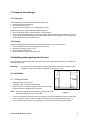
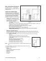
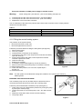
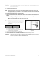
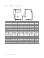
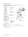
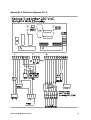
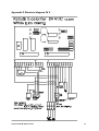
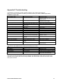
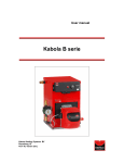
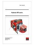
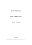
Preface
This user-manual is written to enable the safe operation of the B-series central heating boilers with
integrated calorifier control. The user must read this manual before installation of the boiler and must
follow the instructions within this manual.
Therefore, this manual must be kept with the boiler.
In chapter 2, the safety instructions are detailed, which have to be complied with when installing and
using the boiler. In othe chapters you will fiind safety instructions, that can be identified in the following
way.
Hint: This gives the user suggestions and advise to facilitate the executioon of certain tasks.
Attention:
Additional information is supplied to the user, and possible problems are indicated.
Warning:
Watch out for possible (life-threatening) injuries.
For any remarks, wishes or omissions you can contact your supplier of Kabola Heating Systems. We
also welcome any remarks to improve this manual. We wish you a lot of pleasure from your purchase.
Kabola Heating Systems
Populierenweg 41
NL 3421 TX Oudewater
The Netherlands
Tel:
+31(0)348-561277
Fax:
+31(0)348-562484
Site:
www.kabola.nl
E-mail: [email protected]
© 2005 Kabola Heating Systems
Copying of (parts of) this manual, is only allowed with written consent Kabola Heating Systems.
User manual B–boiler series
2
Table of contents
Preface
Table of contents
1 Introduction
1.1 General
1.2 Range of application
1.3 Product description
1.4 Technical specifications
2 Safety
2.1 General safety
2.2 Safety instructions
3 Transport and storage
3.1 Transport
3.2 Storage
4 Installing and preparing for first use
4.1 Installation
4.1.1 Fitting the boiler
4.1.2 Connection to the central heating system
4.1.3 Connection of domestic hot water supply
4.1.4 Flue gas outlet
4.1.5 Electrical connection
4.1.6 Filling the central heating system
4.1.7 Mounting the oil burner
4.1.8 Connecting the oil filter and oil burner
4.2 Starting your system
5 Operating the boiler
5.1 Explanation of the dashboard
5.2 Operation of the frost guard
5.3 Function of the domestic hot water supply
6 Cleaning and maintenance
6.1 Points for attention
6.2 Cleaning and maintenance
7 End of life of the boiler
Appendix
Appendix A Technical specifications
Appendix B Spare parts
Appendix C Electrical diagram 230 V
Appendix D Electrical diagram 24 V
Appendix E Troubleshooting
Appendix F CE declaration
2
3
4
4
4
4
4
5
5
5
6
6
6
6
6
6
7
7
7
9
10
11
12
12
13
13
14
14
14
14
14
15
16
17
18
19
20
21
22
User manual B–boiler series
3
1 Introduction
1.1 General
Congatulations with your purchase of this Kabola boiler. This user-manual covers the B-series with
intgrated calorifier control. The B-series with integrated calorifier control cover a wide range of boilers
with a broad range of applications. By purchasing this boiler, you have acquired a product, which is of
high quality through the application of the latest European standards and directives.
1.2 Range of application
The B-series boilers with integrated calorifier control are designed to generate heat for the heating of
water for a central heating system. By means of the integrated calorifier control the boilers can also be
used for the generation of domestic hot water through an external calorifier. This calorifier is not
included in the standard boiler set. The dimensions of the rooms to be heated, have to be taken into
consideration.
These boilers are not designed for direct heating of the rooms in which they are installed.
1.3 Product description
The boilers of the B-calorifier series heat the boiler water by means of a pressure jet burner which is
installed on front of the boiler. The boilers are available in both 230 VAC and 24 VDC versions. The
230 VAC model requires a small 24 VDC power supply for control purposes. All B-calorifier series
boilers work in the same way, they only differ in the dimensions and the capacities of the boilers (see
also technical specifications in Appendix A)
For fuel, diesel oil has to be used.
1.4 Technical specifications
The most important technical specifications are listed on the plate on the front of the boiler. More
technical details are listed in Appendix A.
User manual B–boiler series
4
2 Safety
In this chapter we emphasise the safety-related points for operating the boiler.
2.1 General safety
Warning:
Although Kabola Heating Systems designs and producees its products according to
the current safaty standards, it is possible that dangers may present themselves, which
could lead to injuries or damage to the boiler, if the safety instructions in this manual
are not complied with.
The user must:
• Have read and understood the chapter "safety";
• Avoid any actions which may lead to dangers to his health or others;
• Avoid any actions which may lead to damage to the boiler;
• Ensure that the boiler is only used when the boiler is in sound technical condition;
• Ensure that the safety regulations are observed whilst operating the boiler.
Attention:
No alterations to the boilers may be done, without the explicit written consent of Kabola
Heating Systems!
2.2 Safety instructions
In this chapter we emphasise the safety-related points for operating the boiler.
MEASURES FOR A SAFE INSTALLATION
• Don't store any flammable and/or gaseous products in the room where the boiler is installed to
avoid explosions and fires.
• Install the boiler iin a non-humid environment on a firm horizontal base.
• Ensure that there is sufficient ventilation in the room where the boiler is installed (See also § 4.1.1).
• Make sure, before you start connecting the boiler, that the system is disconnected from the power
supply.
• Only use multi-stranded wire for electrical connections.
• Do not change the + pole with the – pole of the battery (for the 24 Volt DC power supply)
MEASURES FOR A SAFE OPERATION
•
•
•
•
•
•
Never change the settings of the burner.
Don't use any aggressive solvents which may affect the boiler (like petrol or turpentine).
Insulate the chimney, when it can be touched by body parts.
Don't damage the fire bricks.
Make sure that the boiler and burner are checked annually by a skilled expert.
Make sure that before you start any work on the boiler that the system is disconnected form the
power supply.
• Make sure that any surplus oil is collected in case of oil spillage.
• We advise you to have any maintenance or repairs carried out by skilled experts.
User manual B–boiler series
5
3 Transport and storage
3.1 Transport
Take following precautions before transporting the boiler:
• Drain the water from the boiler;
• Uncouple the fuel system;
• Remove the burner (see § 4.1.5, replacing the burner).
While transporting the boiler take following precautions:
• Don't damage the boiler, use a blanket to cover the boiler;
• Transport the boiler standing up, is this not possible transport the boiler lying down on its back;
• For the boiler models B-25 onwards use the hoisting eye to move the boiler. This hoisting eye is
located below the top of the boiler cover.
3.2 Storage
Take the following precautions when the boiler is stored for a longer period of time:
• Store the boiler and accompanying parts in a dry place;
• Dismount the burner (see § 4.1.5)
• Store the boiler standing up;
• Store the boiler on a firm horizontal base.
4 Installing and preparing for first use
In this chapter you will find directions and hints for a correct placement and fitting of the boiler and
accompanying parts.
Warning:
Do not storee any flammable or gaseous substances in the room where the boiler
installed. This is to ensure that no explosions or fires can occur.
4.1 Installation
4.1.1 Fitting the boiler
• Install the boiler in a dry place.
• Install the boiler on a firm horizontal base.
• Make sure there is sufficient supply of fresh air in the room
where the boiler is installed (see hint below).
Hint: As a rule of thumb for the ventilation openings, take 2,5
times the diameter of the flue gas outlet.
Figure 1
• To avoid movement secure the base of the boiler by means of spotwelds or with nuts and bolts..
• Keep a minimum distance of 250 mm behind the boiler for the flue-gas outlet (see figure 1).
• Use an earthed plug socket for connecting the 230 Volt AC versions to the power supply.
User manual B–boiler series
6
4.1.2 Connection to the central heating system
PIPING
Take note of the following points, when installing the piping:
• Install the piping in such a way, that the boiler (cover and dashboard) remains accessible;
• Provide enough bleeding points in places where air may collect, especially near the boiler.
Attention:
Install a bleeding point near the boiler, especially when the piping does not go up.
Connect the piping to the boiler as follows (see figure 2):
1. Install the feed to the CH at outlet B of the 3-way valve;
2. Install the return of the CH on the circulation pump
Hint: You may install a shunt with pressure equaliser, when
thermostatic radiator valved are applied.
Attention:
The couplings in the 3-way valve are not sealed at
the factory. Make sure that the couplings are
sealed, preferably with hemp and fitters kit, when
the system is installed.
Figure 2
4.1.3 Connection of domestic hot water supply
Connect the domestic water supply as follows (figure 2):
1. Install the hot water feed to the calorifier to outlet A of the 3-way valve;
2. Install the return from the calorifier on the return of the CH-circuit using a T-connection.
3. Connect the calorifier thermostat according to 4.1.5.
DESCRIPTION OF THE DOMESTIC HOT WATER SUPPLY
When the calorifier drops below its set temperature, the boiler will switch on the heat up the calorifier.
The calorifier has preference over the central heating. When the calorifier is heated, the boiler will be
run at 90°C, whatever the setting of the boiler thermostat is. Once the calorifier has reached the
required temperature, the boiler will continue to heat the calorifier for another 3 minutes. When the
after purge time is finished, the rest of the heat will be dumped in the CH-circuit. The time for the heat
dump is set by the pump timer on the dashboard.
Attention:
The calorifier thermostat must be set to 70°C.
4.1.4 Flue gas outlet
GENERAL
The flue gas outlet is an essential part of your heating installation. An incorrect flue gas outlet reduces
the lifespan of your boiler considerably and has a negative impact on the efficiency. Remember when
installing the flue, that even the best boiler won't work properly unless the flue is properly installed.
Warning:
Because the flue gas temperature lies between 180-240°C, it is advisable to insulate
the flue with heat-resistant material on those parts where contact with human body
parts is possible.
For a correct flue gas outlet the following points need to be observed:
• Use the proper diameter, use a diameter equal to the diameter of the flue gas outlet on the boiler
(see also technical specification).
• Use double-walled chimney pipe outside to prevent a rapid cooling of the dlue gasses, which may
result in condensation in the chimney.
User manual B–boiler series
7
Hint: When using an existing chimney
of a larger diameter than the diameter on
the boiler, you can
install flexible
piping of the correct diameter insides the
existing chimney.
The flue can be installed in several
different ways. You must carefully
coonsider under which circumstances the
boiler will be used. For sea going boats
and sail boats we advise the installation of
a vertical fllue where the heel angles of
the boat may be larger. The following
installationn examples are most common.
− HORIZONTAL FLUE GAS OUTLET
It is possible to fit a horizontal flue gas
outlet to the boiler. The following
points need to be observed:
− The maximum allowed length
Figure 3
is 5 metres.
− Make sure that the outlet is positioned at a sufficient height above the waterline. If this is not
possible use a swan neck bend in the pipe as in figure 3.
− Use the correct hull fittings for installing the flue through a hullside
− Don''t use more than 5 elbows of 90°.
− Every elbow of 90° is equivalent to 1 metre straight pipe
− When a 80x60 silencer is installed, only the last meter of the chimney may be
installed using 60 mm pipe
− VERTICAL FLUE GAS OUTLET
This way if installation is preferable for seagoing boats and sailing boats, because these boats
encounter large angles of heel through waves and under sail. For this kind of flue gas outlet, the
following points are important:
− Install a proper storm cowl oon top of the chimney (thismust stop rain from entering)
(figure 3).
− Install deck fittings for installing the flue through a deck.
− Install a water trap (figure 4), to trap possible water caused by
condensation
− Keep the chimney as vertical as possible.
− Don't use more than 5 elbows 90°.
− The maximum allowed lenght is 10 metres.
− Every elbow of 90° counts as 1 metre.
− Use outside double walled chimney pipe
Hint: To reduce the noise from flames, it is wise to install a silencer in the
flue
Your Kabola supplier can provide you with all components which may be
required for installation such as:
− Cowls;
− Flexible piping;
− Single and double walled chimney pipes;
− Hull and deck fittings;
− Silencers;
− Water traps;
− Insulation.
User manual B–boiler series
Figure 4
8
4.1.5 Electrical connection
Warning:
Disconnect the power supply from the
boiler before you start the installation. The quality of
230 VAC power supply to the boiler should be as
good as the power supply from a land line.
ELECTRICAL CONNECTION
The supplied room thermostat should be installed as
listed below:
− Connecting the room thermostat (see figure 5 and
electrical diagram in Appendix C)
1. Remove the cover of the main connector
situated below the dashboard;
2. Remove, if present, the wire between point 1
and 2;
3. Connect point 1 of the connector to point L
of the room thermostat;
4. Connect point 2 of the connector ro point
L1 of the room thermostat;
Attention:
Figure 5
The core diameter of the connections mentioned above must be 0,75 mm² maximum.
The wires should be suitable for the voltage used.
− Connection of the frost guard
1. Connect the switch to points 3 and 4 of the main connector. (Operation of the frost guard is
explained in chapter 5)
-
Connection of the calorifier thermostat
Connect the calorifier thermostat to the dedicated connections (see Appendix C)
- Electrical installatioon 24 VDC poweer supply for 230 VAC version
Warning:
Never change the + pole with the - pole on the battery (see figure 5).
1. Connect point 5 of the main connector to the + pole of the battery.
2. Connect point 6 of the main connector to the - pole of the battery.
3. Replace the cover on the main connector.
When no 24 VDC power supply is available, an adapter 230 x 24 Volt may be used (Ordernr 9-I051).
When a 12 VDC power supply is available a DC-converter 12 V in 24 V out may be used (Ordernr 15P001).
The wire diameter for the supply mentioned above has to be 1 mm² for the 230 VAC version.
Attention:
The calorifier and room thermostat both switch 24 VDC.
User manual B–boiler series
9
-
Electrical installation 24 VDC power supply for 24 VDC version
Warning:
Never change the+ pole with the – pole on the battery (see figure 5).
1. Connect point 5 of the main connector to the + pole of the battery.
2. Connect point 6 of the main connector to the - pole of the battery.
3. Replace the cover of the main connector.
The core diameter of the wires form points 5 and 6 of the main connector have to comply with the
values from the table below.
Table 1
Distance to the battery
± 6 metres
± 10 metres
± 20 metres
Core diameter
6 mm²
10 mm²
16 mm²
4.1.6 Filling the central heating system
The pressure in the system should:
• Never be lower than 0,5 bar cold;
• Never be higher than 2,5 bar hot.
Follow the procedure below for filling the CH-system (see figure 6):
1. Switch off the boiler;
2. Turn nut (1) loose;
3. Install the hose connection on the opening;
4. Connect the hose with a hose clamp to the connection and slowly
open the valve (2);
5. Fill the system slowly with water, until the pressure indicator
indicates a pressure of 2 bar;
6. Close the valve (2);
7. Bleed the CH-system;
8. If necessary, fill with water again up to 2 bar of pressure;
9. Switch on the boiler and let the pump run for about 5 minutes;
10. Switch off the boiler;
11. Check the water pressure, if it is too low, repeat steps 5
through 10;
12. Remove the hose.
Figure 6
Hint: The CH-system can be filled with cooling fluid, suited for CH-systems (pH-value 8.5)
worden gevuld.
BLEEDING THE CIRCULATION PUMP
The circulation pump can only be bled when the electrical circuit is
connected, because this has to be done with a running pump
Follow the points listed below to bleed the pump (see figure 7):
1. Check if the rotor can rotate without problems by turning the pump
by hand (see manual pump);
2. Loosen the screw on front of the pump 1/2 to 1 turn with a screwdriver;
3. Fasten the srew when water comes out of the opening;
4. The pump is bled.
Figure 7
User manual B–boiler series
10
Attention:
When locking pump couplings are supplief with the boiler, the adjusting grooves must
point towards the pump.
4.1.7 Mounting the oil burner
Hint: Check if the inspection opening on the mounting plate can be reached. If this is not the case
the mounting plate can be turned 180° to reach the opening easier. For a B12 you need to saw
an extra piece off the flance.
The mounting of the burner is done in the following way:
1. Place the nut for the flange bolt in the dedicated position, screw the bolt into the nut and place the
gasket;
2. Mount the flange with 4 supplied M*-bolts and hand tighten these on the mounting plate. The
arrow on the flange should point upward.
Hint: Smear some sealant in the crack in the flange to seal.
3.
3.1. Measure and set the distance from the back of
the gasket mounted behind the mounting plate,
to the front of the flange using the table below
and figure 8;
Boiler type
B12-B17
B25-B35-B45
Distance in mm
60
155
3.2. Scribe the distance on the burner;
3.3. Push the flame tube gently in place up to the
scribed position (see figure 8).
Figure 8
4. Lift de burner a little according to 7A (figure 9);
5. Fasten bolt 7 (Figure 9) on the flange to clamp the burner;
6. The bolts which have been hand tigthened should now be fastened using a spanner.
Attention:
Take care that the flame tube is not damaged during installation. Repairs to the flame
tube are very expensive and don't fall under warranty.
User manual B–boiler series
11
4.1.8 Connecting the oil filter and oil burner
To connect the filter to the burner follow the procedure below (see also figure 9):
Figure 9
1. Remove the burner cover (1);
2. Connect the oil pump (2) to the oil filter (3), using the included fuel hoses. Make sure that the flow
directions on the pump comply with those on the filter;
3. Connect the fuel line from the tank to the filter (5A). The fuel line must have an outer diameter of 8
mm and must be made from copper or steel. The fuel line has to be connected directly to the oil
tank. Correct functioning of the burner can not be guaranteed when a fuel manifol or T connection
is installed;
4. Connect the plug (4) from the boiler to the burner.
Hint: When the oil tank is situated below the boiler or when the oil supply line comes from below the
boiler, it is advisable to use a self bleeding oil filter. This prevents unnecessary
malfunctioning of the burner. In the manual of the burner you will find an overview with the
allowed dimensions
of the oil supply line.
4.2 Starting your system
When everything is connected follow the procedure below:
1. Connect the boiler to the power supply,
Both the 230 VAC and the 24 VDC will need to be connected for the 230 VAC version and only the
24 VDC for the 24 VDC version.
2. Switch the boiler on with the on/off switch on the dashboard. The lamp in the switch will indicate
that the system is active. This lamp is not present in the 24 VDC version. The LED on the top left
of the dashboard should be lighted for both versions.
3. Set the required boiler temperature between 55 and 90°C using the boiler thermostat.
4. Set the room thermostat so that it is switched on (see manual of the room thermostat)
5. Starting of the oilburner (see figure 9):
5.1. Open the valve in fuel line (5);
5.2. Install the bleed hose (3C) on the bleed opening of the oil filter;
User manual B–boiler series
12
5.3. Open the valve on the oil filter (5A);
5.4. Start the oil burner;
5.5. The burner switches on, this wull take approximately 1,5 minutes because of the oil preheating element;
5.6. Open the bleed valve on the oil filter (3B);
5.7. Check if oil is coming out of the hose(3C);
5.8. Check all oil connections for leaks;
5.8.1. If the burner does not start, the control light (8) will light;
5.8.2. Close the bleed valve (3B) on the oil filter;
5.8.3. Wait approximately 3 minutes;
5.8.4. Reset the burner by pushing button (8) and return to 5.4 (repeat if necessary).
5.9. Close the bleed valve(3B) when only oil and no bubbles come out of the hose;
Attention:
The oil burner is tested by the manufacturer, not adjusted. The adjustment of the
burner has to be done by an experienced installer, because this requires expert
knowledge. To be eligible for warranty, the boiler has to be adjusted by an approved
installer. Contact your Kabola supplier to make an appointment.
Never adjust the burner using your own initiative.
5 Operating the boiler
When the boiler has been started and adjusted according to 4.2, operation fo the boiler is very simple.
1. The required temperature is set using the lower knob 8 (figure 10).
2. The after purge cycle of the circulation pump is set with the upper knob 7 (figure 10). This cycle
can be set from 3 to 10 minutes.
The required temperature is set with the room thermostat, which controls the boiler. The calorifier
thermostat controls the 3-way valve on the boiler. The operation of the room thermostat is explained in
the manual of the room thermostat.
If problems arise with the operation of the boiler, you will find a list of possible problems and solutions
in Appendix D.
5.1 Explanation of the dashboard
The LED’s on the dashboard display the active
functions of the boiler
1. This LED indicates if the control panel is
connected to the 24 VDC power supply.
2. This LED indicates if the room thermostat is
switched on.
3. This LED indicates if the frost guard is active.
4. This LED if the burner is active.
5. This LED indicates if the circulation pump is
active.
6. This LED indicates if the 3-way valve is active,
this indicates that the calorifier is heated.
Figure 10
User manual B–boiler series
13
5.2 Operation of the frost guard
The switch which is mounted on the room thermostat is used when you leave the boat and wish to
switch off the central heating system. The central heating system will then only switch on when the
ambient temperature falls + 5°C.
To activate the frost guard follow the procedure below
(figure 11)
1. Switch the frost guard switch (1) on the side of the
room thermostat to the off-position (up);
2. LED 3 on the dashboard is ligthing.
If you only want to use the domestic water supply, follow
the procedure below:
1. Switch the frost guard switch on the side (1) of the
thermostat to the on-position (down);
2. LED 3 on the dashboard is now off.
5.3 Function of the domestic hot water supply
When the calorifier drops below the set temperature, the boiler will switch on to heat the calorifier. The
calorifier has priority over the central heating. When the calorifier is heated the boiler will be run at
90°C, independent of the set boiler temperature. Has the calorifier reached its set temperature, the
pump will continue to run for 3 minutes to provide heat to the calorifier, after which the rest heat will be
diverted to the central heating circuit. Using the pump timer you can determine, how long the pump will
keep pumping water through the central heating.
Attention:
The calorifier thermostat must be set to 70°C.
6 Cleaning and maintenance
6.1 Points for attention
Spare parts must be ordered through your Kabola supplier. For warranty purposes only original spare
parts must be used. When ordering spare parts, state the type of boiler and its serial number. Your
Kabola supplier will then be able to supply the correct parts. In Appendix B, the main spare parts are
listed.
6.2 Cleaning and maintenance
Warning:
Maintenance and repairs should only take place when the boiler is switched ff, this is
because the boiler may start unexpectedly. Take the plug form the wall socket for the
230 VAC versions. Disconnect the power supply for the 24 VDC version.
Warning:
Maintenance and reppairs may only be performed by personnel, who have read and
understood the information in this manual, preferably an expert installer or mechanic
Every week
• Drain the water from the water trap if installed
User manual B–boiler series
14
Every year
1. Clean the boiler;
1.1. Remove the burner (see § 4.1.7);
1.2. Remove the burner mounting plate from the boiler;
1.3. Remove the top cover, be careful not to damge the earthing wire for the 230 VAC
version;
1.4. Remove the top insulation;
1.5. Remove the 4 bolts on the boiler top;
1.6. Remove the boiler top;
Hint: With a B-8 boiler you can remove the upper fire brick to facilitate the cleaning of the
heat exchanger. When replacing the fire brick you have to be careful to fit the fire brick
to the back of boiler..
1.7. Clean the inside of the boiler, using a stiff brush;
1.8. Clean the space between the heat exchanger with a thin metal strip
Attention:
2.
3.
4.
5.
Do not use any aggressive solvents like thinner or gasoline.
1.9. Clean the boiler with a vacuum cleaner;
1.10. Replace the boiler top, if necessary use a new gasket;
1.11. Replace the 4 bolts and fasten these;
1.12. Replace the insulation;
1.13. Replace the top cover of the boiler, make sure the earthing wire is fitted correctly;
1.14. Replace the burner mounting plate and remount the burner (see § 4.1.5).
Clean the chimney;
Clean the watertrap if installed;
Change the oil filter element
Clean the burner (see manual of the burner)
Hint: Kabola Heating Systems has a standard set of replacement parts for the yearly maintenance
(see Appendix B).
Attention:
The old oil filter element has to be processed as chemical waste.
7 End of life of the boiler
When the boiler is scrapped, take note of the points listed below:
• Process the oil filter and the oil hose as chemical waste;
• Separate the metal from the plastic parts and dispose off them separately.
• Process any excess oil in an environmentally freindly way.
• Transport the boiler according to the instructions in chapter 3
• Recycle this manual.
User manual B–boiler series
15
Appendix
User manual B–boiler series
16
Appendix A Technical specifications
Type
A
B
C
D
E
F
G
H
I
J
Chimney ø
Flue gas temp °C
C.H.-connection
IP-value
Burner
230 V
24 V
Nozzle 60°
Nom. Capacity kW min
max
Max oil consumption kg/h
Test pressure in bar
Working pressure in bar
Weight
Water volume
Control range temperature
Insulation thickness in mm
Fuel
Efficiency in %
Waterside efficiency %
Relative standby loss
B-8
B-12
B-17
505
343
356
235
320
70
310
336
400
80
80
170-190
1”
600
347
115
361
243
343
70
325
361
480
80
80
180-240
1”
670
411
115
416
364
408
70
325
416
548
80
80
180-240
1”
2-B009
3-C012
0.40
8.0
11.0
1.2
5
3
50
20
65-90
30
2-B010
3-C013
0.40
11.2
14
1.4
5
3
65
30
65-90
30
97
94
91
88
User manual B–boiler series
B-25
970
455
115
466
283
388
70
385
396
753
100
100
180-220
5/4”
50-11
2-B011
2-B012
3-C014
3-C015
0.50
0.75
14
19.7
19.7
29
1.9
3.3
5
5
3
3
94
118
36
47
65-90
65-90
30
50
HBO 1, HBO 2, diesel of gasolie
91
92
88
89
3%
B-35
B-45
970
455
115
468
284
491
70
385
503
754
130
125
180-230
5/4”
970
445
125
488
284
580
70
385
593
754
150
150
180-230
1½”
2-B013
3-C016
1.00
29
40.7
3.7
5
3
140
64
65-90
50
2-B014
3-C017
1.25
40.7
52.3
5.2
5
3
155
98
65-90
50
92
90
92
90
17
Appendix B Spare parts
Listed below you will find the most important parts for the boilers. These parts can be ordered from
your Kabola supplier, please state type and serial number.
The numbers refer to the image.
1 Boiler top cover
2 Insulation
3
4
5
6
7
8
9
10
Boiler cover
Boiler gasker
Maximum thermostat
3-way valve
Dashboard
NTC-probe
Control PCB
On/Off switch
11
12
13
14
Pump coupling
Circulation pump
Seal 5/4"
Elbow
15 Pressure valve/ pressure
gauge fill/drain cock
16 Main connector
17 Fire inspection opening
18 Oil burner
19 Burner mounting plate
20 Gasket burner mounting
plate
21 Boiler cover side/front
22 Boiler cover back
23 Oil filter (not shown in
picture)
24 Room thermostat (not
shown in picture)
Mineral wool thickness
Appendix A
For B8 a plate
24 VAC!
KBC specification
No light in 24 VDC
version
Two
Dependent on type
(1x1", 5/4x1" or 1½x1")
Wavicom
See specification
max. 25µm, Pmax 6 bar
max. capacity 200 l/h,
total ± 6000 l.
max. vacuum -0,5 bar
L&G REV 11
The following spare parts are available.
25 Nozzle
See technical specifications
For the yearly maintenance Kabola Heating Systems have compiled a set of spare parts often used
during maintenance.
26 Service set consisting of 4+23+25
User manual B–boiler series
18
Appendix C Electrical diagram 230 V
User manual B–boiler series
19
Appendix D Electrical diagram 24 V
User manual B–boiler series
20
Appendix E Troubleshooting
Listed below you will find a list with possible problems, their reasons and solutions.
When you encounter problems not listed, you should contact your dealer. Never try to solve
problems on your own.
Problem
Burner will not start
Possible reason
Oil supply interrupted
Power supply interrupted
Burner stops
Burner starts pulsing
Flame protection dirty (photo cell)
Flame protection defect
(photo cell)
Flue gas flow interrupted
Boiler dirty
Oil supply interrupted
Nozzle defective
Burner shows error
Boiler does not react to thermostat
Water is not circulating
Low voltage
Oil supply interrupted
Wire in main connector has not
been removed (room thermostat)
Boiler thermostat incorrectly
adjusted
Battery of room thermostat flat
Pump couplings are closed
Pump not connected to electricity
supply
Rotor of pump is stuck
Possible solution
Bleed the oil filter
Change contaminated filter element
Fill the oil tank
Check the fuses
Check the power supply
Reset burner (once)
Clean glass of flame protection
Replace flame protection
Clear chimney opening
Clean boiler
See above
Replace nozzle
Reset burner (once)
Check voltage level
See above
Remove wire from main connector
between 1 and 2
Adjust boiler thermostat
Replace battery
Open pump couplings
Connect pump
Turn pump with your hand (see
pump manual)
The LED’s on the dashboard can display the following error codes
LED
Voltage (1)
Fast flashing
Slowly flashing
Slowly flashing
Out
3-way valve (6)
Out
Out
Slowly flashing
Flashing
Reason
Voltage too high
Voltage too low
Probe incorrectly installed or defect
Current too high
3-way valve motor defective
The boiler will reset automatically when the problem has disappeared. Action from the user is only
required when the NTC-probe is incorrectly installed, the user needs to have the connection of the
NTC-probe checked.
User manual B–boiler series
21
Appendix F CE declaration
User manual B–boiler series
22