1
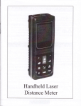
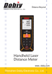
Laser Distance Meter
Operation lnstruction
Congratulations on tbe
prrc:e-- of
our product.
A A frffiH,.#-*t'i"::XHffil]}Tffi
:.
The person responsible for the instrument must ensure
that all users understand these directions and adheie to
them.
Si::bols used
1*::t si-=:bo1s used in the Salety
l::s--:-.:c:o::s :al-e lhe f olion'ing
_ru-E5.
Ar,,--.rirxc,
lndicates a potentially hazardous
situation or an unintended use which, if
not avoided, will result serious injury.
Acaurrou,
Indicates a potentially hazardous
situation or an unintended use which, if
not avoided, may resu-lt in minor injury
and/or in appreciable material,
financial and environmental damage.
€Important paragraphs which must
be adhered to in practice as they enable
the product to be used in a technically
correct and efficient manner.
Use of the instrument
Permitted use
. Measuring distances
.
Computing functions, e.g. areas and
volumes.
Indirect measurement(ftrthagoras
proposition ) .
Plus or minus measurement .
Tilt measuremerrt Prohibited use'
Using the instrument without
instrumerrt.
Using outside the stated limits .
Deactivation of safety systems and
removal of o<planatory and hazard
labels'
Opening of the equipment byusing
tools (screw-drivers,etc.), as far as
not specifically permitted for
certaincases.
t-
. Carqtrng ort modificationor
cwersimof the Product'
. Use afur misaPProPriation'
. Use of acc-essries from other
marnrfactures without
the
'
expre ss
approval.
. Deliberate orirresponsible beha
viouron scaffolding , when using
ladders, when measuring near
machines which are running, or near
parts of machines or in stallations
which are unprotected, aiming
directly intothe sun.
Ddiberate dazzling of third parties;
also in tire dark-
.
,,
F . Inadeguatesafeguards atthe
H survtying site (e.g. when measuring
':' :
I.imits of use .
(F See section "Technical Date"
This product is designed for use in areas
permanently habitable by humans, do
not use the product in explosion
hazardous areas or in aggressive
environments.
3
Areas of responsibility
Responsibilities of the manufacturer of
the original equipment:
It is responsible for supplying the
product, including the User Manual and
original accessories, in a completely safe
condition.
Responsibilities of the malufacturer of
non-original equipment:
€ tfr" manufacturers of non-original
equipment for the product are
responsible for developing,
implementing and communicating safety
concepts for their products. They are se
safetalso responsible for the
effectiveness of they concepts in
combination with the equipment.
Responsibilities of the person in charge
of the instrument:
A
wenuruo
The person responsible for the
instrument must ensure that the
equipment is used in accordance with
the instructions. This person is also
4
accountable for the deployment of
personnel and for their training and for
the salety of the equipment when in use.
The person in charge of the instrument
has the following duties:
. To understand the safety instructions
on the product and the instructions
in the User Manual.
. To be familiar with local salety
regulations relating to accident
prevention.
. To inlorm local dealer immediately if
the equipment becomes unsaJe.
that there is no mechanical damage to
the bumpers.
A
cRurrox'
In using the instrument for distance
measurements or for positioning moving
objects ( e.g. cranes, building
equipment, platforms, etc. ) unforeseen
events may cause erroneous
measurements.
Precautions:
Only use this product as a measuring
sensor, not as a controlling device. Your
system must be configrrred and operated
A
Hazards in use
m€asur€m€xrts if the instrument is
defective or if it has been dropped or has
been misused or modified.
Precautions:
Carry out test measurements
periodically. Particularly alter the
instrument has been subject to
abnormal use, and before, during or
alter important measurements.
Make sure the optics is kept clean and
5
CAUTIoN:
Watch out for erroneous distance
in such a way, that in case of an
erroneous measurement, malfunction of
the device or power failure due to
installed safety measures ( e.g. safety
limit switch ), it is assured that no
damage will occur.
A
wenwINc,
Flat batteries must not be disposed of
6
with household waste.Care for the
environment and take them to the
collecting points provided in accordance
\E
/
...
Ef with national or local regulations.
,,,lftfrn. product must not be disposed
of with household waste.
Dispose of the product appropriately in
accordance with the national .
regulations in force in your country.
Always prevent access to the product by
unauthorized personnel.
Technical Support:
1
llocal dealer.
Electromagnetic Compatibility
{EMc)
The term "electromagnetic
compatibility" is taken to mean the
capability of tJre product.
to function smoothly in an environment
where electromagnetic radiation and
electrostatic discharges are present, and
without causing electromagnetic.
interference to other equipment.
A
WARNING:
The product conforms to the mbst
stringent requirements of the relevant
standards and regulations. Yet, the
possibility of it causing interference in
other devices cannot be totally excluded.
A
ceutror.r:
Never attempt to repair the product
yourself. In case of damage, contact the
local dealership.
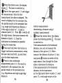
Laser classification
aa@
Integrated distance meter
The distance.meter produces a visible
laser beam which emerges from the front
of the instrument.
8
It is a Class 2 laser product in
accordance with:
IEC6o825-1:2007 "Radiation salety of
laser products"
Laser Class 2 products:
Do not stare into the laser beam or direct
it towards other people unnecessarily.
Eye protection is normally afforded by
aversion responses including the blink
reflex.
A
2 Insert batteries, observing correct E
polarity.
3 Close the battery compartment again.
Replace the batteries when the symbol
flashes permanently in the display.
€
Orrty use alkaline batteries.
€
R"-olre the batteries before any
long period of non-use to avoid the.
danger of corrosion.
weRNIwc'
Looking directly into the beam with
optical lens ( e.g. binoculars, telescopes
can be hazardous.
Precautions:
Do not look directly into the beam with
optical lens.
A ceutloll'
into the laser beam may be
)
Setting the unit for distance
measurements
Press ffi for long time
The following units are available: m
( meter ) , ft ( feet ),in ( inch ),lt +/ in
( feet - inch- 1/ 16)
Beep
press
ffi
for long time to choose BEEP' s
on or off.
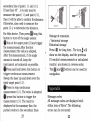
Inserting
1
f
replacing batteries
Remove battery compartment lid and
attach hand strap.
10
continuous (
-X-)the key when
Pr.""
and hold down
I
switching on the device until the
character t"ppear" permanently in the
Laser
display with
b_eep
press of rhe
!
sounds.Every further
i<ey reieases a distance
Press *re kry and hold to
measurement a
switch the device and Laser continuous
operation off.
The correction of tilt sensor
Press long this button !-you are in
the tilt measurement. $ press five times
wherr the bottom of display shows 0.0;
press button 3
the display shows
"rrdl then rotate the
O.1. Wait for 5 sends
instrumerrt by 180 degree. Press the
buttonf , and it shows 0.2; wait till
it shows O.O for finishing the correction.
Press the button {$ tor exiting.
IlluminatingDisplay (+)
!
oroo.rllrresseo snort,,the rnummatrng
display can be turned on or off.
11
Switching on or off
on the instrument and
laser. The display shows the battery
sJmbol until the nort button is pressed.
$Pressing this button lor longer
switches the instrument off.
The instrument switches off
automatically after 3 minutes of
$S*it.tr""
inactivity.
CLEAR button
{&fn.
last action is canceled. While
making area or volume measurements,
each single measurement can be deleted
and remeasured in series.
Reference setting
The default reference setting is from the
rear of the instrument.It will show E..
on the display. {& P."*" long this button
to take the next measurement from the
front edge. The display will show E
& Press thid button, the rear reference
is set again.
12
Level Gauge (6Om instrument)
Press$for long time to choose the level
gauge on or off.
Single distance measurement
$P."". to activate the laser. $ Pr"""
again to trigger the distance measurement.
The result is displayed immediately.
Tilt measurement
measurement ( up to max. +f - 45" and
gp to max. a transverse tilt of +/-10' ).
$er""" the button to collect the
measurement data, and ttre data will be
on the display. And hypotenuse
distance and angle will be on the
auxiliary display.
Minimum / maximum
measurement
(FThe tilt sensor measures tilts
+ 45'
between
(FDuring the measurement of tilt, the
instrument should be held without
transverse tilt, as far as possible,
( + lO' ). (NotincludingTypeDMl )
Horizontal measurement
IPress short button to activate horizontal
measurement in the instrument. The
following syrnbol appears in the
display .dlf tl:e button is active, the
horizontal distance is displayed in the
sunmary line for each distance
13
14
This function ellows the user to measure
the minimum or maximum distance lrom
Addition
a fixed measuring point.It can also be
used as to determine spacings.
It is commonly used to measure room
( maximum values ) or
horizontal distances ( minimum values )
or the difference of maximum and
minimum.
I Pr"*" and hold down this button until
you hear a beep. Then slowly sweep the
laser back and Iorth, up and down over
the desired target point - ( e.g. into the
diagonals
corner of a room ).
! e.""" to stop continuous
measurement. The values for maximum
and minimum distances are shown in
the display as well as the last measured
value in
,'TX
15
I
I
/
subtraction
Distance measuring.
$ tn. nort rneasurement is added to
the previous one.
$ tt e next measurement is subtracted
from the previous one.
This process can be repeated as
required, the measurement will be
displayed in ttre summary line while the
previous one displayed in the secondary
line.
$ tfr"
last step will be reverted.
This function is also available for area
and volume measurement.
Area
{X e."""
once.The
the display.
tz
symbolappears in
e.."" this button to take the first
length measurement ( e.S. length ).
the second
I e.""" it again to take
length measurement (e.S. width ).
The result is displayed in the summary line.
!
16
Volume
]
eress this button twice.The
appears in the display.
,- lsymbol
-7
Rress this button.to take the first
length measurement ( e.g. length ).
take the second
ffress this button to(e.g.
l{ngth measurement
width ).
I e.."" this button ro take the thirci
length measurement ( e.g. height ).
?he volume then appears in the
summary line.
Tilt measurement
&&P.""" this button once to activate the
tilt sensor.The symbol appears in the
display.The -.{ ttlt is continuously
shown
or " %o" depending on the
setting.
I
to measure the inclination and
the distance. (Not including Tupe 4Om
Jer"""
instrument)
Indirect measurement
(
Bzthagoras proposition
)
,,
The instrument can calculate distances
using ftrthagoras proposition.
rvl"t sure you adhere to the
€
prescribed" sequence of measurement:
target points must be in a horizontal
or vertical plane.
The best results are achieved when the
instrument is rotated about a fixed point
( e.g. with the positioning bracket fully
folded out and the instrument placed on
A11
awall).
Make sure that the first measurement
and the distance to be measured are at
right angle.Use the Minimum /
maximum ftinction, as e<plained in
"Measuring -> Minimum / maximum
measurement".
Indirect measurement determining a distance using 2
auxiliary measurements
e.g. for meaduring building heights. It is
helpful to use a tripod.
18
lPr.ss rhis butron once, rhe ciispiay
shows./1 . The laser is switched on.
! eifr-"t rhe upper poinr t i j anci trigger
the measurement. After the first
measurement the value is adopted. The
result is displayed in the summar5z line,
the partial results in the secondary line.
( e.g. Angle and Hypotenuse distance )
If the angle is above 45' , it need to
measure point ( 2 ) . Press $ to switch off
the angle sensor, then must measure the
distance of point ( 1 ). Keep the
instrument as horizontal as possible
durins the measurins.
!e.."" and hold down this button to
trigger continuous measurement, sweep
the laser back and forth, up and down
over the ideal tareet point.
J r.""" ro srop "orrirrro.r"
( 2 ). The result is
measurement point
displayed in the summary line, the
partial results in the secondary line.
( e.g. Hypotenuse and right angle edge
distance )
19
Indirect measurement determining a distance using 3
ar:xiliary measurements
lf Pr""" this button twice; the display
shows the following symbol6l . The laser
xl
is sw'itched on.
If the measurement is the horizontal
distance, you can not measure the
distance of the picture ( 2 ) .When
measure the distance of picture ( 1 )you
need press $ button to switch off the
angle sensor, then through the three
sides to determine the distance.
If the measurement is the horizontal
distance, fix the instrument.
Let the light point direct to point ( 1 ) and
point ( 3 ), read angle values on the
20
secondaryline of point ( 1 ) ard ( 3 ).
If less than 45' , it is only need to
measure the point ( 1 ) and point ( 3 ),
then it will be able to confirm the distance.
Otherwise, also need to measure the
point ( 2 ), to determine the distance.
For 6Om device, Then pressffilong this
bqtton to turn off the angle sensor.
at the upper point (1) and trigger
3*the measurement.AJter the first
measurement the value is adopted.
AJter the measurement, if the angle
sensor is turned off, keep the
i4strument as horizontal as possible.
Qer""" and hold down this button to
trigger continuous measurement.
Sweep the laser up and down over the
ideal target point ( 2 ).
!r.."" .o ".op continuous
measurement ( 2 The value is adopted.
re
Storage of constants
/ historical storage
Historical storage
Press & for long time , The icon S wi[
show on the display, and the previous
10 results ( measurements or calculated
results ) are shown in reverse order.
The ffi and K3buttons can be used for
navigation.
).
rnrs ouTton f,o rngger rne
measurement ( 3 ). The result is
displayed in the summary line, the
partial results in the secondary lines.
!p..""
21
Message codes
All message codes are displayed with
either icon or"Error".The following
errors can be corrected:
22
Icon
+
#
Cause
Calculation
Rmedy
ITEM
ffior,
0.05b@ M.
R@eiving the
2nn
reflrcted light
too weak or too
strong,
Mqaum@t time
too long
R@p6ation, chege a
betts surface refleting or
using tsget pLate.
m6 moasuEmentaruEcy
E, Volum€ measudnq
mbimt
Chmge the light loi
ight is too strong
m€suring.
too high ( +40f ) or
too low ( Ot )
e0-690nm< 1mw
tuElrees0|maht
lhe goal of the
T@peratue
$
Technical Data
dnudsmesurcmsil
Hddwse trror
times.
f the symbol still appeds,
hm you instment may
re defective. Pl@se call
rcu dealer for assistmce-
sDlash*
a
a
a
a
a
a
a
a
a
a
a
a
a
o
and du!
tPa
l0
t0
0c b +4G
F€tuE EngebSbEge
0c b
-4c b +7rc
S@ b 8m0 heasumr
ll3
bSht
23
45.
o
@on eain$
nstment swtral
2800
0.3'
a
a
c.
lwitch on / ofI the
a
o
o
a
"
Cool dom or Wm up
the instrumdt, Extemal
Temperatue will be
available from OC to +40
o
+4(
.201 lo +7rc
5@0
b
8000 measureme.t
x45 x25mm
a5g
24
859
*Use a target plate to increase the
measurement range during daylight
or if the target has poor reflection
properties.
**Measurement could reach 1O m in
good conditions ( good measurement
surface, room temperature ).Under
adverse measuring conditions, such
as the light is too strong, the
measured surface reflective weakly '
or the temperature difference is too
large, or the deviation over distance ,
above 1Om will increase on
+O.2 mm/m.
25
Measuring conditions
Measuring range
The range of 4Om instmment is
limitd to 4O m; and 6Om instrument
is limited to 6Om. At night or dusk and
if the target is in shadow the
measuring range without target plate
is increased.
Use a target plate to increase the
*o"rrorr.€rrt range during daylight
or if the target has poor reflection
properties.
26
Target surfaces
Measuring errors can occur when
measuring toward colourless liquids
( e.g. water )or dust free glass,
styrofoam or similar semi-permeable
surfaces.Aiming at high gloss surfaces
may deflect the laser beam and lead
to measurement errors.Against nonreflective and dark surfaces the
measuring time may increase.
Care
Do not immerse the instrument in
water.Wipe off dirt with a damp,
soft cloth. Do not use aggressive
cleaning agents or solutions.
Handle the instrument as a camera
or telescope.
27
WarrantSz
The instrument comes with one year
warranty.This effective
prerequisite of the warranty is as
follows: You should operating
instructions, handling,
processing, cleaning and maintaining
this instrument, according with our
company's use of instrument, and
maintaining it at good technical
condition. This means that the tools
can only use the original parts
and spare parts from our company.
This warranty only provides free
repair or replacement of defective
parts in the entire expected lifetime
of the tool. If the parts need repair
or replacement due to normal wear
and tear is not in the warrant5r.
28
All illustrations, descriptions and
technical specifications may be
subject to change withoutprior notice.
hdtrmh:
MEttyp6:_
ofNhe:
&ss:_
Nme
Mffi€:k&tucetu6r
D@ofpwlss _
_
Zip
aoel
hdhdon l,"re: _
.fre
whole of
B,@y,
k
dMe me.
fe, eff F&Sc FrAiA de
b4s b@4 H
4iffiedhtutu#ry
29
diry