1
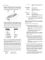
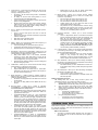
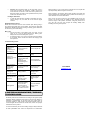
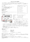
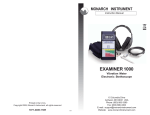
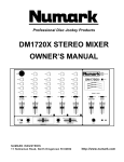
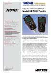
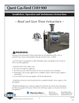
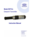
DRIFT EDITION User Manual V 1.0 Thank you for choosing ORCA Products, and welcome to the power and convenience of Brushless RC. By purchasing the Vritra Drift Edition brushless Electronic Speed Control (“ESC”), you have chosen one of the most advanced speed controls designed for all competition. This speed control features ultra smooth torque curve, automatic setup, and multiple programmable parameters (using the included ESC Setting Card). Please read this manual thoroughly to familiarize yourself with the installation, setup, operation, and limitations of this unit. By operating this product, you accept the ORCA Warranty Terms. SPECIFICATIONS System: Forward/Brake/Reverse: Dimensions: Weight: Voltage Input: Peak Current: Typical Voltage drop at 20A High Frequency: Motor Limit: Motor Type: B.E.C.: Multi Protection System: 12 Adjustable Modes (Using included setting card): Brushless Yes (Factory preset at Forward/Brake) 42(L) x 33.5(W) x 33.5(H) mm including fan; 19.5(H) mm excluding fan 65g (excluding wires) (4.8 – 9.9V DC) 4 – 6 Cells NiCD/NiMH 2-Cell LiPO / 2-3 Cell LiFe 360A 0.00864V Yes Over 5.5 Turns Sensored 540 sized brushless motors 6V / 2.0A Yes 1. Timing 2. Turbo Delay 3. Turbo Timing 4. Turbo Interval 5. Punch 6. PWM 7. Drag Brake 8. Initial Brake 9. Brake Frequency 10. Running Mode 11. Battery Mode 12. Overheat Protection To avoid radio glitches, arrange for the placement of the ESC such that the power wires and the receiver antenna wires do not cross over each other. Try to arrange for the receiver placement such that the receiver plugs are easily accessible. Use supplied extension cable if plugs are not accessible (for ESC setup purposes). Position the ESC where it is protected in the event of a crash; and use the supplied double sided tape to secure the ESC onto the chassis. Install/Solder your favorite battery connector to the battery wires if you do not plan to direct solder your battery. RED to +ve and BLACK to –ve. (Warning! Reversing the battery polarity will destroy your ESC and void the warranty) Connect the 3 motor wires to the motor; you can either solder the wires directly to the motor or use your favorite connectors. Match the label of the wires (A, B, C) to the labels of the taps on the motor when soldering. Avoid soldering longer than 5 seconds per solder joint and avoid shorting the motor by creating a wire bridge or a solder bridge on the solder tabs on the motor. (Warning! Improper wiring may damage the ESC and void the warranty.) Connect the sensor cable between the ESC sensor plug and the motor sensor plug Connect the receiver plug to the CH2/throttle pin of the receiver. Secure the on/off switch in a place where it will not be accidentally knocked to the “off” position during a crash. RADIO & ESC SET-UP INSTALLATION & CONNECTORS ON CH1 CH2 Solder the supplied wires to the soldering posts on the ESC according to the following scheme: Red wire “+” post (Battery +ve) Black wire “-“ post (Battery -ve) Blue wire “A” post (Motor A) Blue wire “B” post (Motor B) Blue wire “C” post (Motor C) (Warning! Use good quality solder and avoid soldering longer than 5 seconds per solder joint) OFF Transmitter Settings: Throttle Travel Brake Travel Throttle Exponential Throttle Neutral Trim Throttle Servo Reverse Maximum / 100% Maximum / 100% Start with 0% Center / 0 Reverse (Futaba, KO, Sanwa) Initial set-up of the throttle end-points of the ESC: Connect the power wires of the ESC to a fully charged battery set; making sure the polarity is correct. Bind your receiver and transmitter first if your radio requires you to do so. Turn on the transmitter and hold the throttle at full brake position. Turn on ESC and listen for 2 beeps. After you hear the 2 beeps, apply full throttle and listen for another 2 beeps. Once you hear the 2 beeps, release the throttle to neutral position. A series of beeps will then sound, signifying that the ESC endpoints have been successfully set. Note! If you do not hear the beeping sound as described above, try reversing the throttle reverse setting in the transmitter. RED + BLACK - BLUE . C BLUE . B BLUE . A SENSOR CABLE A B C “Enter” button Customizing the ESC: Due to the different requirements of each type of racing, it is important to customize your ESC for a particular usage. Customization of the ESC is done using the supplied setting card. To start, simply unplug the ESC receiver wire from the receiver and plug it into the receptacle on the side of the setting card (as shown below), making sure that you plug it in correctly: s (signal) White + (+ve) Red - (-ve) Black - Go directly to Menu 15 Screen (Ready to send the changed parameters to the ESC) Menu 13 and 14: “Select” button “” button “” button “Enter” button - Menu 15: “Select” button “” button “” button “Enter” button - Scroll down the menu Scroll up the choices Scroll down the choices Execute (load or save Parameter) and go directly to Menu 15 Screen. Note! Scroll down the menu Scroll up the choices Scroll down the choices Copy current display Parameter on the setting card to the ESC and overwrite old data in the ESC Note! The setting card will compare the Parameters before writing. If no changes are made, the setting card will display “unUpdata”. If changes are made, you will hear a series of beeps and the setting card will display “Send OK”. Connect the battery wires to a charged pack of battery. Turn on the ESC and the setting card will activate automatically. Note that the screen will show “Loading…” during initialization – indicating that the ESC is copying the current setup in the ESC to the setting card. Once loading is completed, the screen will show “ORCA VRITRA-VTC - Program”. You can now start to program your ESC. Press “Enter” to enter the Program Mode. The screen will show the first menu to be programmed – “Timing”. There are 15 menus in the Program Mode and they are listed as follows: Program Menu Factory Preload 1. Timing 0 deg 2. Turbo Delay Off 3. Turbo Timing Off 4. Turbo Interval 0 5. Punch Level 5 6. PWM 8K 7. Drag Brake Off 8. Initial Brake Off 9. Brake Frequency 1.1 KHz 10. Running Mode Forward/Brake 11. Battery Mode Li-xx 2 Cells 12. Overheat Protection 105 degree C 13. Load Parameter Default 14. Save Parameter Parameter 1 15. Send Parameter Yes Menus 1 to 12 are operational settings of the ESC. Each menu consists of its own set of Parameters. Detailed explanation of each menu and its parameter set is found later in this document. It is important that you familiarize yourself with these menu items in order to get the most out of your ESC. Menu 14 allows you to save the current displayed Parameter in the setting card. Maximum of 5 sets of Parameters can be stored. Menu 13 allows you to load either the factory default Parameter or any previously saved Parameters back to the setting card memory. Menu 15 allows you to send the current displayed Parameter on the setting card to the ESC - overwriting whatever is in the ESC. Tips! Whenever in doubt, double check your ESC setting by initializing the setting card again and check each menu setting. Navigation around the Program Menu is done using the 4 buttons on the right hand side of the setting card. The function of each button varies depending on which screen the display is showing: Menu 1 to 12: “Select” button “” button “” button - Scroll down the menu - Scroll up the choices - Scroll down the choices Tips! Do not worry about making mistakes. You will not damage the ESC during setting. If in doubt, you can always reload the default set up and start over again (Load Menu 13 Default and confirm Send on Menu 15). Detailed Explanation of each ESC Menu items: 1. Timing – Allows you to adjust the timing of the motor (14 settings from 0º to 30º in 3º increments): Generally speaking, in brushless systems, increase in timing will result in increase of performance of the motor. However, increase in timing also decrease the efficiency of the system, thus generating heat on the ESC and motor. 0º timing has the most torque and the lowest RPM; 30º timing has the least torque and the highest RPM. With Stock motor start from Timing15 With Mod motor start from Timing 0 Caution! Always monitor motor and ESC temperature closely when applying timing to ESC or motor. Heat may build up very fast in both ESC and motor and cost permanent damage to equipment. 2. Turbo Delay – Allows you to adjust the time gap between the regular Timing (Menu 1) and the Turbo Timing (Menu 3) (16 settings from 0 sec to 0.75 sec in 0.05 sec increments): Turbo Delay is needed because when the ESC is operating under the Turbo Timing mode, it drives the motor to very high RPM - however, with very low torque. With Turbo Delay, the motor has a chance to rev up before the Turbo Timing kicks in. Thus achieving higher top speed. Proper adjustment of the Turbo Delay will result in smooth transition and continuous power band from regular Timing to Turbo Timing. 3. Turbo Timing – Turbo Timing is unique to brushless systems because the ESC can simulate motor timing advance. While mechanical timing advance in brush motor system is limited by the physical phasing of the motor, brushless ESC timing advance can push beyond that physical limit. As a result, motors can run at a super-high RPM in the Turbo Timing nd mode, resulting in a sensation of having a 2 gear/Turbo for top speed. This menu allows you to adjust the amount of Turbo Timing in your ESC Forward/Brake for “STOCK” in 2º increments, Mod Motor for “MOD” in 1º increments (16 settings from 12º to 26º – including “off”): Turbo Timing is applied at full throttle. Higher Turbo Timing settings will increase top speed, but will drive motor and ESC temperatures up as well. Caution! Heat is your biggest enemy! Monitor your ESC and motor temperature to avoid equipment damage. 4. 5. Turbo Interval – Turbo Interval is effective only when Turbo Timing is in operation. It acts as a “ramp-up” for the Turbo Timing (11 settings from 0 to 10): At setting 0, the set Turbo Timing kicks in immediately at full throttle. At setting 10, the set Turbo Timing takes 1.5 sec to reach the preset value after full throttle. Turbo Interval setup is important to ensure high top-end speed on long straightaway. Shorter tracks will favor lower turbo smooth settings, making the turbo very aggressive for more power right away. Longer tracks favor higher settings making it smoother and generate less heat. Punch – Allows you to change the punch of the ESC (Level 1 to Level 10): Level 1 has the least punch and Level 10 has the highest punch. Adjust punch level to maximize acceleration speed with minimum wheel spin. With stock motor, start with Level 7 With mod motor, start with Level 4 6. PWM – Allows you to change the forward drive frequency of the ESC (2K, 4K, 8K, 32K and 64K) A 2K setup will give you good punch at the low end. A 32K setup will result in strong mid to top end. Experiment to find out what suits your driving style best. 7. Drag Brake – Also known as trail braking - allows you to set the automatic brake force applied when the throttle returns to neutral position (16 steps from 0% to 15%): Drag brake affects how a car handles off-throttle (entering a corner). With drag brake on, there will be more weight shift to the front tires thus increasing the front end grip when you let go the throttle. Experiment with different settings to find the setting that fits your driving style most. 8. 9. Initial Brake – Allows you to set the amount of brake during manual braking (11 steps from OFF to 20%): OFF – Brake linear base on transmitter Adjust initial brake to set certain level of “hard brake” effect.(also can adjust your transmitter brake hi-point to get your need the brake force) Brake Frequency – Brake Frequency operates similar to PWM except it affects the braking instead of the throttle (16 steps from 500Hz to 2KHz). At 500Hz, the Drag brake and the Brake force will feel the punchiest. At 2 KHz, the Drag brake and the Brake will feel very smooth. 10. Running Mode – there are 5 modes of operation (Forward/Brake, Forward/Brake/Reverse, Forward/Reverse, Forward/Hold/Reverse, Modify Motor): Forward/Brake is the required for racing situation where reverse is not allowed. Both forward and brake are proportional to radio input. Forward/Brake/Reverse gives you 1 time proportional braking – i.e. when the throttle position goes from forward to brake, the ESC will apply proportional brake to the motor. Once the throttle returns to neutral from the brake position, braking again will be considered as reverse. If the motor is still moving forward at that time, an ESC preset brake force will be applied to the motor until the motor stops and reverse will be applied. Forward/Reverse does not give you control of brake force. When the throttle position goes from forward to reverse, the ESC will apply reverse to the motor. If the motor is still moving forward at that time, an ESC preset brake force will be applied to the motor until the motor stops and reverse will be applied. Forward/Hold/Reverse is similar to Forward/Brake/ Reverse. The difference is that you can brake as many times as you need. Reverse will not be applied until the motor stops. Modify Motor is let you race for modify motor safety auto change to the turbo level from 22º to 36º. 11. Battery Mode – Allows you to change the low voltage protection of the ESC (Ni-xx 5 or 6 cells; Li-xx 2 Cells; LiFe 2-3Cell; or no protection): For Ni-xx cells, the cutoff is set at 0.9V per cell For Li-xx cells, the cutoff is set at 2.8V per cell For LiFe Cells, the cutoff is set at 2.3V per Cell Voltage protect will not shut down the ESC but the output will be limited to 50% power. No protection is only recommended for serious racing application that requires every second of run time. Do NOT use this setting unless you are absolutely sure. You may ruin your battery packs in one run. 12. Overheat Protection – Allows you to cancel overheat protection: There’s a temperature sensor on the ESC circuit board and the overheat protection is set at 105ºC (220ºF). The ESC will not shut down when the temperature is reached but the output will be limited to 50% power. No protection is only recommended for extreme racing conditions when you are prepared to destroy your ESC trying to finish a race. ESC damaged due to this setting will not be covered under warranty. Do NOT use this setting unless absolutely necessary. 13. Load Parameter – Allows you to load the saved Parameters in the setting card memory to the setting card display menu (6) with user defined Parameters: Loading saved Parameter does not change the ESC setting. It only changes the setting card display Parameter. In order to change the ESC setting, you still need to “Send” the Parameter to the ESC (Menu 14). 14. Save Parameter – Allow you to save the setting card display Parameter to the selected memory Parameters in the setting card (5 user defined Parameters): This feature allows you save Parameters for future use. It also allows easy sharing of ESC setup amongst team members. 15. Send Parameter – Allow you to send the setting card display Parameter to the ESC (Yes / No): Yes to confirm or No to cancel sending Note that the original parameter in the ESC will be lost after this operation. Setting Card Utility Functions: The Setting Card has 2 other utility functions (Timer and Temperature Gauge). To access these utility functions: 1. Power-up the setting card using a LiPO transmitter pack Caution! Make sure that the polarity of the plug is correct. 2. Once the setting card power-up and show “VTC PRO SPEC- Program”, press the “” button or the “” button to choose timer or temperature gauge. Press Enter to select. 3. Using the Timer: Press Enter to start/stop timing Press the “” button to reset Press Select to return to initial screen 4. Using the Temperature Gauge: Press Enter to show the temperature Press Select to return to initial screen OPERATING TIPS Multi Protection System – Other than the Low Voltage Protection and the Overheat Protection that were described above, the ESC has 2 more build-in protections: Motor Lock Protection: The ESC is protected against damage when the motor is stuck and does not turn at all. Power will not be applied in this situation. Caution! Since the ESC relies on the feed back of the 3 motor wires to deploy this protection, it ONLY works if the motor does not turn AT ALL. If the rotor has any rotation, the ESC will consider the motor to be operational and the power to the motor will not be cut off. Fail Signal Protection: In case the radio signal to the ESC is interrupted for over 1 second during a run, the ESC will cut off until the signal resumes. ROAR Stock Spec Racing: ROAR has announced the new class of Stock Spec Racing using a zero degree timing ESC and 17.5 turn Motor. The Vritra Pro Spec ESC satisfies the ROAR requirement showing a blinking green LED when set at 0 timing and 0 turbo timing. before sending in your unit for repair. Products sent in for repair that operate perfectly will be charged a service fee. When sending in the product, always pack carefully and include the original sales receipt, a description of the problem encountered, your return address and contact information. Since we do not have control over the installation and use of this product, we cannot accept any liability for any damages resulting from the usage of this product. Therefore, using this product is at your own risk, and the user accepts all resulting liability from installing and using of the product. Misc. Tips: Connect the ESC to the battery pack only when you are ready to run. This will avoid draining the battery pack. Always disconnect the battery after your run. A small spark may occur at the connection when the battery is connected. This is normal and is due to the charging up of the capacitors. Troubleshooting Guide: SYMPTOM POSSIBLE CAUSE REMEDY Continuous beeping once battery is connected (unit not turned on) Broken signal wire to receiver Replace signal wire Throttle setting reversed Reverse throttle setting Transmitter setting changed after initial set-up; or steering/throttle moved during turnon of ESC Reset transmitter and recalibrate ESC Motor running in reverse when accelerating forward Incorrect motor-wire connection Reconnect motorwires correctly Steering servo working, but motor not running Wiring problem Check for wiring shortage at the motor tabs ESC switches off frequently Overheating due to wrong motor selection or gearmesh problem Change motor or check out gearmesh Radio glitches Transmitter battery too low; broken receiver antenna wire; or power wires too close to receiver Check for different causes and fix problem Continuous Beeping once unit is turned on LIMITED WARRANTIES / REPAIR PROCEDURES All ORCA products are manufactured according to the highest quality standards. ORCA guarantees this product to be free from defects in materials or workmanship for 60 days from the original date of purchase verified by sales receipt. This limited warranty does not cover damages that are results of normal wear, misuse or improper maintenance of the product. To avoid unnecessary service and mailing charges, always eliminate all other possibilities and check all components for malfunctions Team ORCA [email protected]