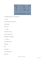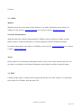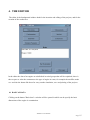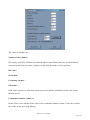
1
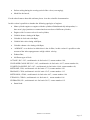
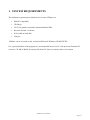
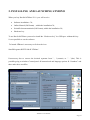
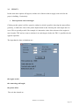
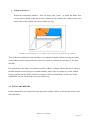
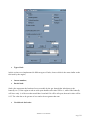
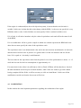
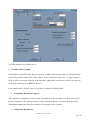
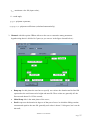
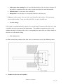
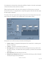
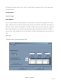
4TMono V1.0
User Manual
16/12/2004
Written by: Eng. Fernando Ortenzi
4TMono User Manual
Page
1
INDEX
SOFTWARE FEATURES
pag.3
1. SYSTEM REQUIREMENT
pag.3
2. INSTALLING AND LAUNCHING 4TMono
pag.3
3. 4TMono MENU'
pag.3
3.1 FILE
pag.3
3.2 UTILITY
pag.3
3.3 RESULTS
pag.3
3.4 HELP
pag.3
3.5 EXIT
pag.3
4. THE EDITOR
pag.3
4.1
BASIC DATA
pag.3
4.2
FUEL PARAMETERS
pag.3
4.3
COMBUSTION
pag.3
4.4
SIMULATION PARAMETERS
pag.3
4.5
VALVES GEOMETRY
pag.3
4.6
INLET DUCT
pag.3
4.7
EXAUST DUCT
pag.3
4.8
RUNNING THE SIMULATION
pag.3
4.9
SAVING THE PROJECT
pag.3
4.10 MAIN MENU'
pag.3
4.11 PRINT THE PROJECT
pag.3
5. RESULTS
pag.3
6. GLOSSARY
pag.3
4TMono User Manual
Page
2
SOFTWARE FEATURES
4TMono is a four stroke spark ignition simulation software; it's capable to estimate the
performances of such engines and it’s therefore an excellent tool both in design and tuning phase.
The software utilization is very simple and allows the visualization of many motoristic variables
useful in the field of internal combustion engines. 4TMono can visualize more than 60 graphs for
every simulation, in such manner, every part of the engine can be observed adequately: the
advantages of 4TMono are then, the possibility to study and optimize "4 stroke engines" with the
possibility to get information that can't be easily obtained in experimental way.
Such results can be printed like 'Files', so they can be used as input data for other programs and also
in text format '.txt' ,easily printable.
The technical features of 4TMono are:
•
"Two zones" combustion model; during the combustion phase, the gas in the cylinder is
divided in two components: the "mixture" and the "combustion products". Such combustion
products are in chemical equilibrium, while the mixture is retained to be at constant
composition. The combustion model utilized is the “Blizard-Keck”;
•
Zero-dimensional turbulence model over all the thermodinamic cycle; such model supply
the initial values for the combustion and for the heat transfer between gas present in the
cylinder and its walls; also heat transfer is divided in “two zones”;
•
Blowby: model for the calculation of the mass lost of mass across the piston rings;
•
Calculation of the chemical equilibrium of the combustion products; it take in consideration
13 chemical elements: N 2 , N , NO, NO2 , O2, O, OH , H ,H 2H 2O , CO, CO2 , Ar , while the
mixture is composed by: N 2 , O 2, H 2O, Ar ;
•
Monodimensional model for inlet and exhaust ducts: the model used is “Two Step LaxWendroff “ + TVD, in which it takes account of the variation of cross sectional area, friction
losses, heat transfer, variation of the thermodynamic properties of the gas and of its
composition;
•
Monodimensional model for the boundaries of the ducts; the method used is the "CIR", and
the solution is calculated every instant in non linear systems of equations instead of load
solutions from disk;
•
Three-dimensional discharge coefficients maps for inlet and exhaust valves; such
coefficients, it’s known, depend both from the valve lifting, and from the pressures ratio
upstream and downstream of it;
4TMono User Manual
Page
3
•
Perfect mixing during the overlap period of the valves (scavenging);
•
Model for the knock;
For the other features about this software please view the scientific documentation.
In this version is possible to simulate the following typologies of engines:
•
Mono-cylinder engines or engines with the cylinders fluidodinamically independent, i.e.
there aren’t pipe junctions or connections between ducts of different cylinders;
•
Engines with 2 or more valves for each cylinder;
•
Variable advanc e timing with Rpm;
•
Variable air- fuel ratio with Rpm;
•
Variable inlet valve timing with Rpm;
•
Variable exhaust valve timing with Rpm;
•
“AIR BOX”: or to the box in which there is the air filter; in this version it’s possible to take
account of the inlet soprappressure at high vehicle velocity;
•
Exhaust Box;
•
8 different type of fuels:
OCTANE; H/C=2.25 ; stechiometric air-fuel ratio=15; octane number=100;
UNLEADED GASOLINE; H/C=1.65 ; stechiometric air- fuel ratio=14.37; octane number=96;
LEADED GASOLINE; H/C=1.87 ; stechiometric air-fuel ratio=14.64; octane number=98;
METHANE; CH4; stechiometric air-fuel ratio=17.23; octane number=120
PROPANE; C3H8; stechiometric air- fuel ratio=15.67; octane number=112
METHANOL; CH4O ; stechiometric air-fuel ratio=6.47; octane number=106
ETHANOL; C2H6O ; stechiometric air- fuel ratio=9 ; octane number=106
HYDROGEN; H2 ; stechiometric air- fuel ratio=34.07; octane number=112
•
Partial load.
4TMono User Manual
Page
4
1. SYSTEM REQUIREMENTS
The minimum requirements to install and to execute 4TMono are:
•
IBM PC compatible;
•
CD Player;
•
256 VGA graphic card with resolution 800x600 DPI ;
•
Browser Internet 4 or better;
•
20 free Mb on hard disk;
•
Usb port
4TMono can be executed on the versions of Microsoft Windows 9X/ME/NT/XP.
For a good utilization of the program it is recommended however a PC with processor Pentium III
or better, 128 Mb of RAM, obviously with faster PC there are shorter times of execution.
4TMono User Manual
Page
5
2. INSTALLING AND LAUNCHING 4TMONO
When you buy Rtz-Soft 4TMono V1.0 yo u will receive:
•
Software installation Cd;
•
Online Manual (Pdf format) , within the installation Cd;
•
Scientific documentationin (Pdf format), within the installation Cd;
•
Hardware key.
To use Rtz-Soft 4TMono you need to install the “Hardware key” in a USB port: without this key
it’s not possibile to use the software.
To launch 4TMono is necessary to click on the icon
StartàProgramsàRTZ-Softà’4TMono’.
It’snecessary also to convert the decimal separator from '' , ''(comma) to " . "(dot). This is
possibile going to windows Control panel à internazional and language options à “N umbers” and
there make these modifies.
4TMono User Manual
Page
6
3. 4TMONO MENU'
The menu bar, located on the top left of the main window has 4 options: File, Utility, Results, Exit,
that will be explained.
3.1
FILE
Clicking on the menu FILE it's possible to choose the following options:
3.1.1
New Project:
With this option an empty project will be opened in which it’s possible to specify all the dimensions
of the engine: many windows will be opened and inside of them the necessary values will be
introduced to make a simulation. If all of the values weren’t introduced or if reasonable values were
not introduced, the program will inform the user at the moment of the closing of the window; in the
same way, when when you decide to start a simulation the program will advice of any omitted or
wrong values.
3.1.2
Open existing Project:
Clicking on this option a window will be opened in which it will be necessary to specify an existing
project previously created from 4TMono ; such file has an extension “. dat”.
3.1.3
Exit from the program:
Clicking on this option it will be ask subsequently to Exit from the program and, if this is the action
wanted, it will be necessary to click on “O K” to exit definitively.
4TMono User Manual
Page
7
3.2
UTILITY
In this menu three options will appear, and the role of them is that to supply some tools for the
project’s building. Particularly:
•
Piston position and crank angle:
Clicking on this option it will be opened a window in which is possible, knowing the manovellism
geometry, to obtain the value of the piston displacement in mm. knowing the crank angle and vice
versa. This is specially useful if for example it is known the value of the advance of the engine in
mm. from the TDC and we want to calculate it in crank degrees before the TDC; is possible also the
opposite operation.
The input data for these calculations are:
the engine stroke;
the connecting rod length;
the piston offset.
The exit data instead are:
4TMono User Manual
Page
8
The piston displacement in mm. : (if the crank angle is known) or the crank angle in function to
the piston displacement;
The crank radius : if the offset is different from zero the crank radius is not more the half of the
stroke, therefore also this is useful information;
TDC crank Angle relative to the vertical line : if the offset is not zero the TDC will be not relative
zero;
Angle of BTC relative to the vertical line: In the same way like above.
•
Create valve lift profile file:
4TMono has a sufficiently comprehensive method of a lot of the most spread valve lift
profiles. If however there is particular profile to test, it is possible to create it in the window
that it will be opened after clicking on "Create valve lift profile file".
In this window the profile of valve lift will be specified for points, i.e. for every degree (or
fraction of degree) of crank the value of the valve lift will be introduced in mm.
The profile is begun to write from the angle zero, i.e. the moment in which the valve begins
to lift coincides with the zero.
4TMono User Manual
Page
9
Before beginning to write such values it is necessary to specify how many points will be
writed.
There are then two tools that try to facilitate the creation of a valve lift file:
the first one produces, knowing the number of points that the user will specify and from the
angular increment chosen, all the column that represents the angles;
the second, starting from an existent profile, allows to change max valve lift.
The project has to be saved to be used subsequently from the simulator, clicking on the
button 'Save file'.
It is possible also to open an existing file to modify it, clicking on the button "Open file".
To close the utility it is sufficient to click on "Main Menu".
It is possible then also to visualize a graph with the created profile and to see if it was
written correctly or if the profile corresponds to that desired.
•
Create discharge coefficients file:
4TMono User Manual
Page
10
4TMono has a lot of configuration files for discharge coefficients; nevertheless if the user has
specific maps of an engine, it is possible to create the files and then introduce them in the simulator
with the utility 'Creates file discharge coefficients'.
Within the window, there are:
•
a grid in which the user introduces the discharge coefficients for the flow "from duct to
cylinder" (inflow);
•
a grid in which the user introduces the discharge coefficients for the flow "from cylinder to
duct" (ouftlow);
•
a field in which is necessary to introduce the number of points in which the user must
specify the 'Lift valve/Max valve lift';
•
a field in which is necessary to introduce the number of points in which the user must
specify the 'upstream/downstream Pressure ratio'.
With these tools is possible to create easily the map of the discharge coefficients.
4TMono User Manual
Page
11
To change only some values of an existing map (loaded with the button 'Open file') it is sufficient to
click on the field wanted and, below the grid, change the value contained in the box, after that to
click on 'Modify'.
To close the utility it is sufficient to click on 'main Menu'.
3.3
RESULTS
In this menu we have the following options:
View graphic results:
Clicking on this option it will be possible to view the results of the simulation in graphic format: at
the conclusion of each simulation, 4TMono will create a file '. out', i.e. a file that contains the
results that can be visualized like graphs.
First it will asked what file '.out' to be opened and, then, will appear a series of graphs on the main
window of 4TMono and a series of button that will allow to change the pages, each with a different
set of graphs. For further details look at the chapter. 5.
View the results in text mode:
Clicking on this option it will be possible to view the results of the simulation in text mode. In the
same way of the results in graphic mode, 4TMono will create some files'. txt' that contain the results
of the simulation in text mode and that are then visualized in the main window of the program.
After having specified the file '.txt' to open, on the screen will appear a window that contains in text
mode all the information results of a simulation. Easily consultable and printable through a button
situated on the right top in the main window
Unity of measure:
In 4TMono is possible also to change the measure unity of the results; allowing to choose, by the
user, the measure unity desired.
4TMono User Manual
Page
12
The parameters that can be customized are:
•
Power:
The possible measure unities are :
Kilowatt (Kw);
Horses (Cv);
•
Torque:
The measure unity is:
Newton x meter (Nm);
Kilograms x meter (Kgm)
•
Pressure:
The measure unity is:
Pascal (Pa);
Bar;
Temperature:
The measure unity is:
Kelvin (K);
4TMono User Manual
Page
13
Celsius C.
3.4
HELP
Manual:
With this option the present help will be visualized. For further information on the features of
4TMono see the web site www.rtz-soft.com or to send an e- mail to [email protected] .
Scientifica documentation
With this option the scientific documentation of 4TMono will be opened in an Adobe Acrobat
Reader window: in this document there are all the equations ut ilized to build this simulator.
For further information on the features of 4TMono see the web site www.rtz-soft.com or to send an
e-mail to [email protected]
About:
In this window are visualized the information relative to the version of the software and to the site
web where it's possible to find further information on the software and how contact the author.
3.5 EXIT
Clicking on this option, a window will be opened that will ask to exit the software; it is equivalent
to the option 'Exit 4TMono' from the menu 'File.
4TMono User Manual
Page
14
4. THE EDITOR
The editor is the fundamental window both for the insertion and editing of the projects, and for the
creation of the results files.
In the editor the data of an engine are subdivided in varied groups that will be explained; there is
then a space to write the comments to the type of engine in exam, for example the modifies made
ecc. and also the button like those for carry out the simulation, save and printing of the projects.
4.1 BASICAL DATA
Clicking on the button "Basic data" a window will be opened in which can be specify the basic
dimensions of the engine in examination.
4TMono User Manual
Page
15
The values to introduce are:
Number of the cylinders:
like already said before, 4TMono can simulate engines multicilinder that have not fluidodinamic
connections and if there are more cylinders, in this field the number can be specified:
Bore mm.:
Stroke mm. :
Connecting rod mm. :
Offset mm. :
If the engine presents an offset between the piston axis and the crankshaft axis,this value can be
introduced here;
Combustion chamber Volume cc. :
In this field it can be introduced the value of the combustion chamber volume. It does not consider
the volume of the spark plug filleting;
4TMono User Manual
Page
16
•
Volume interstizi cc.:
Within the combustion chamber , there are many little “zones”, in which the flame front
can’t penetrate (during combustion). Such volumes are for example the volume between the
lateral walls of the cylinder, the piston and the top ring.
Schematic representation of the cervices within an engine considered in the software during simulation.
There is then an useful tool for the calculation of combustion chamer volume knowing the unitary
swept volume and the compression ratio; this tool is made to facilitate the operation of the data
insertion;
For return back in the editor it is sufficient to click on 'Back', 4TMono will do therefore a check of
the data introduced and will report eventual mistakes, while if the user wants to go back without
having completed all the fields, it will be necessary to click on 'main Menu'. In this case all the
modification carried out from the last rescue will be lost
4.2 FUEL PARAMETERS
In this window there are reported the most important variables relative to the fuel that will be used
and particularly:
4TMono User Manual
Page
17
•
Type of fuel:
in this version were implemented 8 different types of fuels; choose which is the most similar to the
fuel used by the engine;
•
Octane number;
•
Partial load:
Such value represents the fraction of area crossable by the gas through the inlet throat (carb,
butterfly ecc.). If the engine works at wide open throttle such value will be 1, while if the butterfly
will leave only ¼ of the area that would have been had if it will be all open, then such value will be
0.25. The value has to be greater of zero and to be not greater than one.
•
Variable air-fuel ratio:
4TMono User Manual
Page
18
If the engine is carburetted (but also with injection system), is known that the air- fuel ratio is
variable. In this case is taken that this value change with the RPM, i.e. the user can specify for every
RPM the relative value. In this field the user must specify if this is retained variable or not:
If it is fixed, it will ask to introduce only the value of equivalence ratio and will be the same for all
of the RPM;
If it is variable there will be a grid to compile in which one column represents the RPM and in the
other the user must specify the value of the equivalence ratio.
The equivalence ratio is an adimensional value and is the ratio between stoichiometric air- fuel ratio
and the desired air fuel ratio: in practice it is greater than 1 for the rich mixtures and less for the
lean; if it is equal to 1 obviously is stoichiometric.
The best value for the equivalence ratio from the point of view of the performances is about 1.1-1.2
while the best one for the low consumptions is approximately 0.9.
For return back in the editor it is sufficient to click on 'Back', 4TMono will do therefore a check of
the data introduced and will report eventual mistakes, while if the user wants to go back without
having completed all the fields, it will be necessary to click on 'main Menu'. In this case all the
modification carried out from the last rescue will be lost.
4.3 COMBUSTION
In this window the most important parameters regarding the combustion of the engine.
4TMono User Manual
Page
19
The fields that have to be filled up are:
•
Variable advance timing:
in this field it is specified if the advance timing is variable or not; this procedure is conceptually the
same to that for the setting of the values relative to the "Variabe air- fuel ratio", i.e. if the advance is
fixed, it will be necessary to specify only that value, while in the second case it will be necessary to
edit a grill associating to an RPM its advance.
If the model used is “Wiebe” then it’s necessary to input the following data:
•
Combustion duration in degrees:
After which the combustion is started, (time of incubation or ignition delay) it will be necessary to
specify its duration. This value generally is about 40-60 and depends a lot from the shape of the
combustion chamber and from the turbulence level present in the cylinder.
•
Combustion parameters:
4TMono User Manual
Page
20
In this field the user has to introduce all of the values relative to the combustion; that are:
1. Time of incubation of the combustion in degrees:
from the moment of the ignition of the spark, there a little time in which the combustion is not
appreciable, such value generally is about 10-20 degrees, and generally the higher values
correspond for higher RPM..
•
AWiebe: is a representative value of the quantity of mixture that burns during the combustion:
for Awiebe=6.906 the mixture that burns is 99.999% of the present one in the cylinder;
generally is a values of experimental nature;
•
MWiebe: is a representative value of the quality of the combustion, named also “shape factor”.
For low values of MWiebe, most of the combustion happens in the first degrees, while for high
values in the end. Such value is about 1-2 (for a 4 stroke engine about 1.5) and is a value of
experimental nature; .
If the user haven't experimental data, it's possible to define some common values that are sufficient
for most of the applications:.
The user could define:
Time of incubation in degrees: 0
Combustion duration: 50-60 degrees (or however a value that try to take the advance nearest
possible to the real one; if the anticipation is high, generally means that the combustion duration is
long);
AWiebe: 6.9;
MWiebe: 2.
If the model used is “Turbulent ” then it’s necessary to input the following data:
•
Combustion chamber type : “disc” o “emispheric”;
For the disc shaped chamber it’s necessary to insert also:
•
Spark plug position;
4TMono User Manual
Page
21
This value is representative of the distance of the spark plug from the extremity of the
combustion chamber: if it’s ‘0’ then the spark plug is completely offset, while if it’s 0.5 it’s
centred.
Generally it’s convenient to use the Disc shaped chamber and set this value to 0.3, and make the
calibration with the experimental data.
•
Plug electrodes distance mm.;
•
Turbolence parameter;
This value is about unity and if sperimental data are not available, leave this value to 1.5
However for higher values we have higher turbulence levels, vice versa for the lower ones: the
range of this value is between 0.5 and 3.
•
Cylinder walls temperature : in this field it will be necessary to introduce the temperature
of the cylinder liner: generally such value should not exceed 180 °C (indicating value
150°C);
•
Piston temperature: such values generally fluctuates around 200-250 °C;
•
Head temperature: such value generally fluctuates around 250-300 °C;
•
Heat transfer coefficients: to evaluate the heat transfer between cylinder and its walls it’s
necessary put in 3 coefficients of the following: Nu = a ⋅ Reb ⋅ Pr c .
These three parameters are generally evaluated experimentally and, if experimental data are
not available , use the following values:
a=0.07;
b=0.8;
c=0.33.
For return back in the editor it is sufficient to click on 'Back', 4TMono will do therefore a
check of the data introduced and will report eventual mistakes, while if the user wants to go
back without having completed all the fields, it will be necessary to click on 'main Menu'. In
this case all the modification carried out from the last rescue will be lost.
4TMono User Manual
Page
22
4.4 SIMULATION PARAMETERS
In this window there are all of the parameters necessary to lead the simulation of a specific project.
These parameters are:
•
Initial RPM;
•
Final RPM;
•
RPM for graphic output;
•
RPM step;
With these four parameters the user must specify the initial RPM and final RPM of the simulation,
while in this interval with the parameter "RPM step" can specify the step; the "RPM for graphic
output" is that in which 4TMono gives better informations, because it creates a number of graphs,
not only with the RPM, but also with the crank angle.
•
Simulation parameters:
In this case there are two options:
1. "Auto": 4TMono will determine automatically the better configurations to lead the
simulation;
4TMono User Manual
Page
23
2.
"
Manual" : the user must specify some parameters to define, that are:
a) Pipe step factor of inlet duct mm.;
b) Pipe step factor of exhaust duct mm.;
The simulation models of the internal combustion engines, divide the ducts in many little segments
(that have the lenght of the "pipe step factor”) for study the behaviour of the gas and therefore for
supply the necessary values for the study of the cylinder thermodynamics: every duct is divided in
many small segments, and the two values above formulated are them length.
These variables influence strongly the accuracy of the results, but also the times of computation,
because with smaller values of pipe step factor the results are more accurate, but the computation
time is longer. Generally for the inlet duct, a value of 10 mm. is more than sufficient while for the
exhaust it can be used a value of 20 mm.
In the definition of these values, it's important to keep in mind that the pipe step factor have to be
always sufficiently smaller of the smallest segment of duct, otherwise the information of them can
be lost during the simulation.
c)
Minimum number of iteration;
during a simulation, 4TMono, for each RPM, carries out a certain number of iteration (or
revolutions of crankshaft) before passing to the successive one: generally are sufficient not much
iterations to have good results. In this field it will be introduced its lower value, i.e. even if the
simulator arrives to sufficiently small error before this value, it will still continue in that RPM, until
it will exceed it.
d) Maximum number of iteration;
It is not sure that however that in every configuration the program reach a sufficiently small value
of the error for each Rpm, i.e. it doesn’t arrive at convergence and therefore it’s well to specify also
the maximum number of iteration beyond which the simulator doesn’t go, to pass then to the
successive Rpm. In the hypothesis above described, 4TMono makes however a media of the all the
variables on more iteration to make the error however low.
•
Ambient temperature °C;
4TMono User Manual
Page
24
•
Ambient Pressure Bar;
•
Humidity %Vol.
These instead are the ambient conditions in which the engine is simulated.
Regarding the inlet conditions, the vehicle velocity could influence the engine performance.
The valued to be added, to take account of this phenomenon are::
•
Global gear-ratio;
This is the ratio between the engine Rpm and the traction wheels rpm.
•
Traction wheels radius mm.
For return back in the editor it is sufficient to click on 'Back', 4TMono will do therefore a check of
the data introduced and will report eventual mistakes, while if the user wants to go back without
having completed all the fields, it will be necessary to click on 'main Menu'. In this case all the
modification carried out from the last rescue will be lost.
4.5 VALVES GEOMETRY
In this window there are all the values relative to the inlet and exhaust valves: the approach is
precisely the same both type of valves and in this section will be explained only the inlet one.
4TMono User Manual
Page
25
The parameters that have to be set are:
•
Inlet cam profile:
The law of the valve movement, and therefore indirectly the profile of the cam that moves it, have
to be known to carry out a simulation. In 4TMono there are 3 different ways to define such
problem, that are:
1. Polinomial:
The valve profile is treated as a polynom of the following manner:
(
y = Lmax − a ⋅θ 2 + cp ⋅θ p + cq⋅ θ q + cr⋅ θ r + cs⋅ θ s
)
where
y: valve lift;
4TMono User Manual
Page
26
Lmax : maximum valve lift (input value);
θ : crank angle;
p,q,r,s: polynom exponents;
a,cp,cq,cr,cs: polynom coefficients (calculated automatically).
2. Manual: with this option 4TMono allows to the user to customize many parameters
hypothesizing that it is divided in 5 parts (as you can see in the figure located below) :
•
Ramp up: for this phase the user have to specify two values: the duration and its final lift
expressed as the ratio between its height and max lift. These values are generally 40° the
first one and about 0.2-0.25 the second;
•
Main lift up: this is the main phase of the curve;
•
Dwell: expresses the duration in degrees of that part of curve in which the lifting remains
constant and equal to the max lift: generally such value is about 5-10 degrees, but it can be
also null;
4TMono User Manual
Page
27
•
Lobe center after opening: Here it is specified the duration of the rise phase in degrees. If
the profile is symmetrical, then this value is equal to the half of the total inlet duration.
•
Main lift down: it is the same of the main lift up.
•
Ramp down: also this phase is conceptually identical to the Ramp up.
3.) Discrete: in this manner, if the user had a own lift profile, and therefore a file opportunely
created with the utility "Create valve lift profile file", it can be specified here.
•
Variable timing:
If the engine in examination has the capacity of to vary the angle of opening of the inlet valve, then
is possible also to keep account of this phenomenon. The method to compose the grid, or of to
introduce the angle of opening of the valve, is conceptually the same of the case of the variable airfuel ratio or of the advance timing.
•
Valve dimensions:
to define correctly the geometry of the inlet valves, is necessary to specify the following values:
1. Number of valves for each cylinder:
4TMono User Manual
Page
28
2. outer valve diameter mm. :
3. inner valve diameter mm. :
4. Port diameter mm. :
5. valve steam diameter mm.
The graph of the figure quoted above gives an idea of them.
Discharge coefficients file:
in this field it will be necessary to specify the file that contains the information regarding valve
discharge coefficients. Such file can be built with the utility "Create discharge coefficients file ", or
can be chosen between those defaults of 4TMono.
For return back in the editor it is sufficient to click on 'Back', 4TMono will do therefore a check of
the data introduced and will report eventual mistakes, while if the user wants to go back without
having completed all the fields, it will be necessary to click on 'main Menu'. In this case all the
modification carried out from the last rescue will be lost.
4.6 INLET DUCT
The maximum configuration of this version of 4TMono is that reported in the figure below:
4TMono User Manual
Page
29
It is had therefore in inlet and in the exhaust the possibility to introduce a box and a certain number
of ducts before them (in inlet) and after (in exhaust).
When the grid representative of the ducts will be composed, it will be necessary to respect the
direction of the arrows: it is begun therefore to compile the segments of the ducts from left to right;
the upper graph is explanatory.
The window "Inlet duct" begins with the request of the presence of an inlet box and, in base to the
answer of the user, will appear a series of fields relative to such volume to fill up.
In the positive case it will be necessary to introduce the following data:
•
Number of ducts: it is hypothesized that upstream of the volume there is a number greater
than one of equal ducts.
•
Volume cc. : Here have to specify the box volume in cc.
•
Box temperature °C; to keep account of the heat exchange between the gas and his walls
this value is necessary. Nevertheless this value is generally very similar to the environment
temperature;
•
Duct temperature: The same of the previous value ;
•
Belmouth entry /Belmouth exit: here have to specify the end duct type, plain or belmouth:
obviously the last gives better performances;
4TMono User Manual
Page
30
To introduce the data relative to the duct, it is subdivided in segments and for every segment the
user must insert:
Initial diameter,
Segment length,
Final diameter.
The convention, like previously explained, is to introduce the values of the segments from left to
right: in the previous case the first segment (and therefore the first line of the grid) will be that on
the left at contact with the atmosphere (or with the volume if is present). It is necessary however to
add a further length for every end with the atmosphere about the half of the diameter (0.5*D) to
keep account of the end effects (the part sketched in the figure submitting represents only the left
end).
Main duct
The figure below represents the main duct:
4TMono User Manual
Page
31
•
Belmouth entry:
Like for the previous case it is specified the type of end (that on the left in the figure), while for the
opposite one, there will be the valve;
•
Inlet duct temperature :
Here it is introduced the value of the main inlet duct temperature; in this case the value would be
greater than the environmental temperature and if it is not known, a value included between 6080°C would be sufficiently reasonable;
•
Duct composition grid:
to introduce the data relative to the duct, it is subdivided in segments and for every segment are
introduced:
Initial diameter,
Segment length,
Final diameter.
The convention, like previously explained, is to introduce the values of the segments from left to
right: in the previous case the first segment (and therefore the first line of the grdl) will be that on
the left at contact with the atmosphere (or with the volume if is present). It is necessary however to
add a further length for every end in contact with the atmosphere about the half of the diameter
(0.5*D) to keep account of the end effects of end (the part sketched in the figure represents only the
left end).
4TMono User Manual
Page
32
•
Distance collettor-valve mm. :
to introduce this value is necessary to have special caution. To introduce a value sufficiently
precise, is necessary to introduce besides the mean value of such segment, (as it can be seen in the
figure) a further length of the order of the half of the valve diameter.
•
Visualize duct profile:
to have an idea of the duct introduced, clicking on this button will appear a graph that will visualize
it.
For return back in the editor it is sufficient to click on 'Back', 4TMono will do therefore a check of
the data introduced and will report eventual mistakes, while if the user wants to go back without
having completed all the fields, it will be necessary to click on 'main Menu'. In this case all the
modification carried out from the last rescue will be lost.
4.7 EXHAUST DUCT
This is the same of the inlet case and therefore for every information return to the previous section.
4TMono User Manual
Page
33
4.8 RUNNING THE SIMULATION
If the user has chosen to run the simulation, will appear a window in which will be visualized in real
time the results. For all of the time of the simulation it will be not more possible to perform other
operations on 4TMono, and is dissuaded from use other programs, in fact the simulation will use all
the resources of the PC, and less operations there are in course, more rapid will be the simulation.
4.9 SAVING THE PROJECT
To save the current project, there is the button 'Save project'. All the files are saved with an
extension '.dat', so that can be re-used subsequently.
4.10 MAIN MENU'
If it is wanted to return to the main menu, is sufficient to click on this button, but is necessary to
remember always to save the modifies, otherwise they will be lost.
4TMono User Manual
Page
34
4.11 PRINTING THE PROJECT
If the user wants to print a copy of the current project, is sufficient to click on 'Print the project'.
4TMono will create a document with all of the input parameters.
4TMono User Manual
Page
35
5. RESULTS
The results of a simulation can be presented both in graphic form and in text form.
When it is chosen the option "View simulation graphs" from the menu "Results" will appear a
screen for the selection of the results file: such file have an extension '.out' and preserve the name of
the initial project. For example if the project simulated it is called 'G50.dat', the results file will be
'G50.out'.
After to have chosen the results file will appear a screen like this:
In the centre of the page there are 4 graphs and to the right there are a certain number of buttons that
serve to choose the type of graphs that has to be visualized and some operations that can be
accomplished over them.
4TMono User Manual
Page
36
Clicking two times on a graph it will appear an enlargement of that which will carry it to have
dimensions larger than the original ; to restore then the initial dimensions is necessary again to click
two times on the graph.
The graphs are divided in two groups:
•
RPM: here are grouped all of the graphs presented with X axis as RPM and every button
will present 4 graphs:
1. Cilinder pag.1: here are reported the graphs of Power, Torque, specific Consumption and
thermal efficiency.
2. Cilinder pag. 2: here are reported the graphs of BMEP, Max pressure in the cylinder, MAx
Temperature in the cylinder and knock index. If knock index is greater than one, there is
detonation.
3. Cilinder pag.3: here are reported the graphs relatives to the engine scavenging, that are:
scavenging efficiency, delivery ratio, Volumetric Efficiency, trapping efficiency.
4. Duct before the inlet box: here are reported the graphs of mean Temperature, mean Pressure,
mean Speed and mean Purity of such duct;
5. Inlet box: here are reported the graphs of mean Temperature, mean Pressure and mean Purity
of such box;
6. Main inlet duct: here are reported the graphs of mean Temperature, mean Pressure, mean
Speed and mean Purity of such duct;
7. Main exhaust duct: here are reported the graphs of mean Temperature, mean Pressure, mean
Speed and mean Purity of such duct;
8. Exhaust box: here are reported the graphs of mean Temperature, mean Pressure and mean
Purity of such box;
9. Duct after the exhaust box: here are reported the graphs of mean Temperature, mean Pressure,
mean Speed and mean Purity of such duct;
4TMono User Manual
Page
37
•
Crank angle: When it is specified the "RPM for graphic output"', it is established on what
regime are wanted further output informations. In fact, at that RPM, will be visualized
graphics with X axys as crank angle:
1. Cylinder pag.1: In this page there are the graphs of Pressure, Temperature,the combustion
curve and the graphs relatives to the temperatures of the mixture, of the combustion products
and of the mean between the two;
2. Cylinder pag.2: In this page there are the graphs of the pressure in the cylinder, the inlet and
exhaust valve lift, the pressure-volume diagram and of the Work;
3. Duct before the inlet box: here are reported the graphs of Temperature, Pressure, Speed and
Purity of such duct;
4. Inlet box: here are reported the graphs of Temperature, Pressure and Purity of such Volume;
5. Main inlet duct: here are reported the graphs, Pressure, Speed and Purity of such duct;
4TMono User Manual
Page
38
6. Main exhaust duct: here are reported the graphs of Temperature, Pressure, Speed and Purity of
such duct.
7. Exhaust Box: here are reported the graphs of Temperature, Pressure and Purity of such box;
8. Duct after the exhaust box: here are reported the graphs of Temperature, Pressure, Speed and
Purity of such duct.
•
Load other results: if the user wants to compare more results it is sufficient to click on this
button and will appear a window for the selection of other projects; it does not exist a
superior limit to the maximum number of results that can be visualized, obviously with a lot
of curves visualized the graphic will be more muddled.
•
Enlarge graph: If the graph was already enlarged is possible to enlarge further a part of it
specifing the inferior and superior limit of it. Clicking on this button will appear a window
in which it'possible to specify such limits in base to the part of graph that the user wants to
visualize.
•
Print: If the user wants to print the graphs visualized in the main window, is necessary to
click on this button. The graphs visualized in that moment will be printed, i.e. if in the main
window are visualized 4 graphs, will be printed 4 graphs, in the case instead that a graph is
enlarged, then it will be printed alone in foreground.
•
Save graph as image: is simile to the previous case, with the difference that the graph or
the graphs will be saved as ". bmp" image.
•
Create file results: If the user wants to use the results of 4TMono as input data for other
programs is possible to create some files with all of the results: in the directory "Results" it
will be created a file for every variable. Every file will be constituted by two columns of
numbers: one will be the RPM (or the crank angle) and the other will be the variable of
interest (power, torque or the pressure with the crank angle).
•
Exit from the graphs: exit out from the graphs page.
4TMono User Manual
Page
39
6. GLOSSARY
In this chapter are reported the definitions of the main motoristic parameters presented in this
software: it will be neglected those simpler (Power, Torque etc.)
BMEP: Breake mean Pressure;
IMEP: Indicated mean Pressure;
FMEP: Friction mean Pressure (represents the mechanical losses of the engine);
Scavenging efficiency: it is the ratio between the mass of mixture and the total mass present in the
cylinder at the end of the inlet phase; it is remembered that generally in the cylinder are always
present the products of the combustion of the previous cycle. It is practically an index of the
"Quality" of the fluid substitution phase.
Delivery ratio: it is the ratio between the total mixture sent in the engine from the inlet valve and a
reference mass; the last is the product between a reference density (at the temperature of 20°C and
pressure of 1 atm) and engine swept volume. It is an index of the quantity of air aspirated from the
engine.
Charging efficiency: is the ratio between the mixture really retained at the end of the inlet phase
and the reference mass definite before. It is also the relation between the scavenging efficiency and
the delivery ratio.
Trapping efficiency: is the ratio between the mixture really retained at the end of the inlet phase
and the total mixture sent from the inlet valve. It is also this an index of the quality of the fluid
substitution.
Purity: represents the fraction of mixture present in the fluid inside a duct; if such value is 1 then
the gas is constituted only by mixture, while if equal to 0 is composed only by combustion
products.
Detonation index: This index supplies information on the mixture and precisely if during the phase
of combustion arrives at knock. If such value is greater than 1 it can be retained that there is knock,
the opposite if is smaller than 1.
4TMono User Manual
Page
40