1
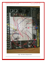
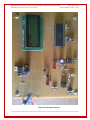
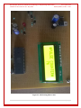
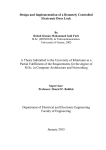
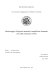
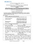
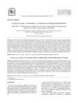
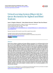
International Journal of Advanced Technology in Engineering and Science www.ijates.com Volume No.02, Issue No. 07, July 2014 ISSN (online): 2348 – 7550 DESIGN OF A LOW COST PULSE COUNTER Dinesh Sharma1, Dinesh K. Atal2 1,2 Department of Biomedical Engineering, Deenbandhu Chhotu Ram University of Science and Technology,Murthal, Sonepat, (India) ABSTRACT The pulse counter is designed using red light detection from light that passes through a patient’s finger from an emitter. The absorption of this red light will tell when blood is moving through the finger and how much compression is there by the artery against bone. Heart rate exhibiting direct proportional characteristics with change in blood volume during heart beats can be measured by modeling an analog amplification and analog to digital conversion scheme. The output of this analog circuit will be fed into an Atmel ATmegaS52 microcontroller, which will compute the pulse from this analog signal. The microcontroller will output a count to a general purpose LCD so that the patient’s signals can be monitored. Keywords: Atmel ATmegaS52 microcontroller, LCD, Analog Amplification, Analog to Digital Conversion I INTRODUCTION 1.1 Heart Rate Measurement Heart rate is the speed of the heartbeat, specifically the number of heartbeats per unit of time. The heart rate is typically expressed as beats per minute (bpm). Heart rate is measured by finding the pulse of the heart. This pulse rate can be found at any point on the body where the artery's pulsation is transmitted to the surface by pressuring it with the index and middle fingers; often when the heart is not beating in a regular pattern, this is referred to as an arrhythmia. These abnormalities of heart rate sometimes, but not always, indicate disease. It is compressed against an underlying structure like bone. (A good area is on the neck, under the corner of the jaw.) The thumb should not be used for measuring another person's heart rate, as its strong pulse may interfere with the correct perception of the target pulse. The radial artery is the easiest to use to check the heart rate. However, in emergency situations the most reliable arteries to measure heart rate are carotid arteries. This is important mainly in patients with atrial fibrillation, in whom heart beats are irregular and stroke volume is largely different from one beat to another. 1.2 Pulse Counter Heart rate can be measured either by the ECG waveform or by the blood flow into the finger (pulse method). The pulse method is simple and convenient. When blood flows during the systolic stroke of the heart into the body parts, the finger gets its blood via the radial artery on the arm. The blood flow into the finger can be sensed 345 | P a g e International Journal of Advanced Technology in Engineering and Science www.ijates.com Volume No.02, Issue No. 07, July 2014 ISSN (online): 2348 – 7550 photo electrically. To count the heart beats, here we use a small light source on one side of the finger (thumb) and observe the p change in light intensity on the other side. The blood flow causes variation in light intensity reaching the light- dependent resistor (LDR), which results in change in signal strength due to change in the resistance of the LDR. 1.3 Atmel AT89C51 Microcontroller The AT89C51 is a low-voltage, high-performance CMOS 8-bit microcontroller with 4K bytes of Flash programmable and erasable read only memory (PEROM). The device is manufactured using Atmel‟s highdensity nonvolatile memory technology and is compatible with the industry-standard MCS-51 instruction set. By combining a versatile 8-bit CPU with Flash on a monolithic chip, the Atmel AT89C2051 is a powerful microcomputer which provides a highly-flexible and cost-effective solution to many embedded control applications. The AT89C2051 provides the following standard features: 2K bytes of Flash, 128 bytes of RAM, 15 I/O lines, two 16-bit timer/counters, a five vector two-level interrupt architecture, a full duplex serial port, a precision analog comparator, on-chip oscillator and clock circuitry. In addition, the AT89C2051 is designed with static logic for operation down to zero frequency and supports two software selectable power saving modes. The Idle Mode stops the CPU while allowing the RAM, timer/counters, serial port and interrupt system to continue functioning. The power-down mode saves the RAM contents but freezes the oscillator disabling all other chip functions until the next hardware reset. 1.4 Literature Review 1.4.1 Microcontroller Based Heart Rate Monitor This paper describes the development of a heart rate monitor system based on a microcontroller. It offers the advantage of portability over tape-based recording systems. The paper explains how a single-chip microcontroller can be used to analyse heart beat rate signals in real-time. In addition, it allows doctors to get the heart beat rate file of the patient by email every twenty four hours. It can also be used to control patients or athletic person over a long period. The system reads, stores and analyses the heart beat rate signals repetitively in real-time. The hardware and software design are oriented towards a single-chip microcontroller-based system, hence minimizing the size. The important feature of this paper is the use of zero crossing algorithm to compute heart rate. It then processes on real-time the information to determine some heart diseases. [4] 346 | P a g e International Journal of Advanced Technology in Engineering and Science www.ijates.com Volume No.02, Issue No. 07, July 2014 ISSN (online): 2348 – 7550 1.4.2 A low cost optical sensor based heart rate monitoring system Heart rate exhibiting direct proportional characteristics with change in blood volume during heart beats can be measured by modeling an analog and digital manipulation scheme. A model of a single Microcontroller chip based heart beat counter, capable of data storage and suitable for remote communication via Bluetooth, would be designed and implemented and checked for contrast with a commercial heart beat per minute (BPM) counter. [5] 1.4.3 All-Digital On-Chip Monitor for PMOS and NMOS Process Variability Utilizing Buffer Ring with Pulse Counter This paper proposes an all-digital process variability monitor which utilizes a simple buffer ring with a pulse counter. The proposed circuit monitors the process variability according to a count number of a single pulse which propagates on the buffer ring and a fixed logic level after the pulse vanishes. The proposed circuit has been fabricated in 65 nm CMOS process and the measurement results demonstrate that we can monitor the PMOS and NMOS variabilities independently using the proposed monitoring circuit. The proposed monitoring technique is suitable not only for the on-chip process variability monitoring but also for the in-field monitoring of aging effects such as negative/positive bias instability (NBTI/PBTI). [6] 1.4.4 Real-time physiological signal measurement and feedback system A real-time physiological signal measurement and feedback system is suitable to be worn on a body part of an user for decreasing the noise of motion, and includes a sensor module, a signal processing module and a feedback platform. The sensor module includes a first magnetic unit having a light emitting diode and a second magnetic unit having a photo-detector. The light emitting diode illuminates a light beam passing through the body part and being received by the photo-detector so as to generate an electric signal when both of the first and the second magnetic units attract mutually to sandwich the body part. The signal processing module converts the electrical signal into a digital signal. The feedback platform processes the digital signal to generate a physiological parameter, and is used as a multi-function driving recorder. An alarm is triggered or not by the feedback platform according to the physiological parameter. [7] 1.4.5 Microcontroller based heart rate monitor using fingertip sensors This paper presents the design and development of a microcontroller based heart rate monitor using fingertip sensor. The device uses the optical technology to detect the flow of blood through the finger and offers the advantage of portability over tape-based recording systems. The important feature of this research is the use of Discrete Fourier Transforms to analyze the ECG signal in order to measure the heart rate. Evaluation of the device on real signals shows accuracy in heart rate estimation, even under intense physical activity. The performance of HRM device was compared with ECG signal represented on an oscilloscope and manual pulse measurement of heartbeat, giving excellent results. Our proposed Heart Rate Measuring (HRM) device is economical and user friendly. [8] 347 | P a g e International Journal of Advanced Technology in Engineering and Science www.ijates.com Volume No.02, Issue No. 07, July 2014 ISSN (online): 2348 – 7550 II COMPONENTS OF CIRCUIT 2.1 Components List ICl LM358 operational amplifier IC2 AT 89C51 microcontroller LCD 16mm LCD LED1 LED2 5mm LED Resistors (all ¼-watt, ±5%carbon) 10kilo-ohm, 47-kilo-ohm, 100-kilo-ohm, 1-kilo-ohm, 330ohm, 1.2 kilo-ohm, 10 kilo-ohm resistor network Capacitors: 470nF ceramic disk, 0.1µF ceramic disk, 470µF, 16V electrolytic, 10µF, 16V electrolytic, 22pF ceramic disk Miscellaneous: On/Off switch X - 11.0592MHz crystal 6V battery 2.2 IC LM358 These amplifiers have several distinct advantages over standard operational amplifier types in single supply applications. They can operate at supply voltages as low as 3.0 V or as high as 32 V, with quiescent currents about one−fifth of those associated with the MC1741 (on a per amplifier basis). The common mode input range includes the negative supply, thereby eliminating the necessity for external biasing components in many applications. The output voltage range also includes the negative power supply voltage. 2.2.1 Features Short Circuit Protected Outputs True Differential Input Stage Single Supply Operation: 3.0 V to 32 V Low Input Bias Currents Internally Compensated Common Mode Range Extends to Negative Supply Single and Split Supply Operation ESD Clamps on the Inputs Increase Ruggedness of the Device without Affecting Operation NCV Prefix for Automotive and Other Applications Requiring Unique Site and Control Change These Devices are Pb−Free, Halogen Free/BFR Free and are RoHS(Restriction of Hazardous Substances) Compliant 2.3 Capacitors It is an electronic component whose function is to accumulate charges and then release it. To understand the concept of capacitance, consider a pair of metal plates which all are placed near to each other without touching. If a battery is connected to these plates the positive pole to one and the negative pole to the other, electrons from the battery will be attracted from the plate connected to the positive terminal of the battery. If the battery is then disconnected, one plate will be left with an excess of electrons, the other with a shortage, and a potential or voltage difference will exists between them. These plates will be acting as capacitors. Capacitors are of two 348 | P a g e International Journal of Advanced Technology in Engineering and Science www.ijates.com Volume No.02, Issue No. 07, July 2014 ISSN (online): 2348 – 7550 types: - (1) fixed type like ceramic, polyester, electrolytic capacitors-these names refer to the material they are made of aluminum foil. (2) Variable type like gang condenser in radio or trimmer. In fixed type capacitors, it has two leads and its value is written over its body and variable type has three leads. Unit of measurement of a capacitor is farad denoted by the symbol F. It is a very big unit of capacitance. Small unit of capacitor is picofarad denoted by pf. 2.4 Liquid Crystal Displays (LCD) Certain organic large size molecule types of liquids possess properties, which cause them to interfere with light passage in them. One type, called the twisted nematic type, is becoming more useful in today‟s LCDs. In this, the liquid crystals have thread-like shapes: the units join head to tail for million molecules to form lengthy chains. Moreover each plane is twisted a few degrees from the next. Some of the recent chemicals of this variety are made of pyrimidines, phenyl cyclohexanes, bicyclohexane and 4-(4‟ methoxy benzylidine) -n-butylaniline. They exhibit a crystalline structure even in liquid form at ordinary temperatures. The property of the liquid is anisotropic in the two perpendicular directions. The cell thickness is so designed that there is a 900 turn of the molecules between the top and the bottom faces. The twisted nematic has the property that twists light, which passes through it. Polaroid filters are fitted above and below the cell so that light is polarized as it enters, and is twisted through 900, exiting through a filter kept at 900 to the one at top. The light is then reflected via a mirror at the back and returns via the same pathway. One glass plate has the 7 segment electrodes etched on it and a conductive coating of tin oxide or Tin cum Indium oxide. The other plate has the common electrode. The conductive coat is treated further for good surface contact to liquid. The cell when assembled appears as clear glass: the segments are not visible. When a voltage is applied between the plates, the molecules move with the dipoles aligned in the cell axis. Thus those regions under the segments, which have the electric field, have a contrasty appearance when viewed in light, while other unexcite segments are invisible.The voltage needed is preferable 2-20 V A.C. The cathode (or front plane) voltage input to the LCD goes through an „analog switch‟ that is on at any time so that a.c. voltage is applied to the appropriate segment. The anode (back plane) receives the a.c. supply. The frequency is 30-32 Hz. 2.5 Crystal Oscillators Crystal oscillators are oscillators where the primary frequency determining element is a quartz crystal. Because of the inherent characteristics of the quartz crystal the crystal oscillator may be held to extreme accuracy of frequency stability. Temperature compensation may be applied to crystal oscillators to improve thermal stability of the crystal oscillator. Crystal oscillators are usually, fixed frequency oscillators where stability and accuracy are the primary considerations. For example it is almost impossible to design a stable and accurate LC oscillator for the upper HF and higher frequencies without resorting to some sort of crystal control. 2.6 Light-Dependent Resistor (LDR) A light-dependent resistor (LDR) or photocell is a light-controlled variable resistor. The resistance of a photoresistor decreases with increasing incident light intensity; in other words, it exhibits photoconductivity. A 349 | P a g e International Journal of Advanced Technology in Engineering and Science www.ijates.com Volume No.02, Issue No. 07, July 2014 ISSN (online): 2348 – 7550 photoresistor can be applied in light-sensitive detector circuits, and light- and dark-activated switching circuits.A photoresistor is made of a high resistance semiconductor. In the dark, a photoresistor can have a resistance as high as a few mega ohms (MΩ), while in the light, a photoresistor can have a resistance as low as a few hundred ohms. If incident light on a photoresistor exceeds a certain frequency, photons absorbed by the semiconductor give bound electrons enough energy to jump into the conduction band. The resulting free electrons (and their hole partners) conduct electricity, thereby lowering resistance. The resistance range and sensitivity of a photoresistor can substantially differ among dissimilar devices. Moreover, unique photoresistors may react substantially differently to photons within certain wavelength bands. 2.7 Circuit Description The setup uses an LED for light illumination of flesh on the thumb behind the nail and the LDR as detector of change in the light intensity due to the flow of blood, The photo-current is converted into voltage and amplified by operational amplifier IC LM358 (Id). The detected signal is given to the non-inverting input (pin 3) and its output is fed to another non-inverting input (pin 5) for squaring and amplification. Output pin 7 provides detected heartbeats to pin 12 of the microcontroller. Preset VRI is used for sensitivity and preset VR2 for trigger- level settings. Microcontroller IC AT89C51 is at the heart of the circuit. Port-1 pins P1.7 through P1.2, and port-3 pin P3.7 are connected to input. These pins are pulled-up with 10-kilo-ohm resistor network RNW1. They drive all the segments of the 7-segment display with the help of inverting buffer IC3. The display is selected through port pins P3.0, P3.1 and P3.2 of the Microcontroller (IC2). Port pins P3.0 down through P3.2 are connected to the base of transistors T3 through T1, respectively. Pin 6 of IC goes low to drive transistor T1 into saturation and provide supply to the common-anode pin (either pin 3 or pin 8) of DIS1.Similarly, transistors T2 and T3 drive common-anode pin 3 or 8 of7-segment displays DIS2 and DIS3, respectively. Only three 7segment displays are used. 1C2 provides segment-data and display-enable signals simultaneously in timedivision-multiplexed mode for displaying a particular number on tie 7-segment display unit. Segment-data and display-enable pulses for the display are refreshed every 5‟ ms. Thus the display appears to the continuous, even though it one by one. Switch S2 is used to manually reset the microcontroller, while the power on reset signal for the microcontroller is derived from the combination of capacitor C4 and resistor R8. An 11.0592MHz crystal is used to generate the basic clock frequency for the microcontroller. The circuit is powered by a 6V battery. Port pin P3.6 of the microcontroller is internally for software checking. This pin is actually the output of the internal analogue comparator, which is available internally for comparing the two analogue levels at pins i2 and 13. As pins 12 and, 13 of IC2 can work as an analogue comparator, these are used for sensing the rise and fall of the pulse waveform and there by evaluate the time between two peaks and hence the beat rate. The output of the pulse preamplifier is fed to pin 12 of microcontroller. Pin 13 of the microcontroller is connected to the preset for reference-level setting of the comparator. Thus voltages at pins 12 and 13 are always compared. The rise and the fall at pin 12 are sensed by the program. The internal timer of the microcontroller is used to find the time taken for one wavelength. This time is converted into the heart beat rate in beats per minute 350 | P a g e International Journal of Advanced Technology in Engineering and Science www.ijates.com Volume No.02, Issue No. 07, July 2014 ISSN (online): 2348 – 7550 by a pre-calculated look-up table. The program notes the time between the high-to- low and low-to-high transitions of the wave. This time in microseconds is converted in steps of 4 ms for comparison with the values already stored in the look-up table. This number is used to find (from the look-up table) the heart rate in beats per minute. The number so obtained is converted into a 3-digit number in binary-coded decimal (BCD) form. The same is output to the 7-segment LED displays in a multiplexed manner. The display shows the rate for a while and proceeds to another measurement. Thus beat rates obtained from time to time are visible on the display. Figure 1 Circuit Diagram 351 | P a g e International Journal of Advanced Technology in Engineering and Science www.ijates.com Volume No.02, Issue No. 07, July 2014 ISSN (online): 2348 – 7550 Figure 3 Breadboard Implementation 352 | P a g e International Journal of Advanced Technology in Engineering and Science www.ijates.com Volume No.02, Issue No. 07, July 2014 ISSN (online): 2348 – 7550 Figure 4 PCB Implementation 353 | P a g e International Journal of Advanced Technology in Engineering and Science www.ijates.com Volume No.02, Issue No. 07, July 2014 ISSN (online): 2348 – 7550 Figure 5 LCD Showing Pulse Count 354 | P a g e International Journal of Advanced Technology in Engineering and Science www.ijates.com Volume No.02, Issue No. 07, July 2014 ISSN (online): 2348 – 7550 III RESULTS The setup uses an LED for light illumination of flesh on the thumb behind the nail and the LDR as detector of change in the light intensity due to the flow of blood; the photo-current is converted into voltage and amplified by operational amplifier IC LM358. The first phase of the device, the optical receiver and transmitter, is constructed and tested. The output of the receiver is connected to an O-scope to obtain the heartbeat signal. The IC LM358 is used to properly amplify the signal. The measured voltage level does not differ much for different ages except for kids under the age of three. Kids under the age of three have significant low voltage level compared to adults while counting a beat. After the amplification stage, measured voltage for a beat in case of adults is more than 1.2 V, while for infants the voltage is around 0.5 V. Therefore the generation of peaks may vary and results from the microcontroller may also vary.The microcontroller is programmed to count the number of peaks of the input signal in 1 minute. The LCD is connected to the microcontroller and a known frequency pulse signal is fed into it. The correct number of peaks per minute value is showed on the LCD. When the microcontroller is integrated into the entire design circuitry, it is able to count the number heartbeats per minute and drive the LCD to display the counted value. IV CONCLUSION & FUTURE SCOPE 4.1 Conclusion The project low cost pulse counter has been accomplished successfully. This can detect the pulse of person according to the compression of radial or dorsalis pedis artery against the hand or foot finger respectively. The detection process takes one minute because the counter increases the count for one minute and LED keeps glowing for one minute as well. This model is demonstration of the pulse counters currently used in the world. But it is designed using the low cost components, so that it can reach to the masses and poor people. This project has its application in the developing countries like India, because of the more people below poverty level are there. 4.2 Future Scope A graphical LCD can be used to display a graph of the change of heart rate over time. Sound can be added to the device so that a sound is output each time a pulse is received. The maximum and minimum heart rates over a period of time can be displayed. Serial output can be attached to the device so that the heart rates can be sent to a PC for further online or offline analysis. Warning for abnormalities (such as very high or very low heart rates) can be displayed on the LCD or indicated by an LED or a buzzer. 355 | P a g e International Journal of Advanced Technology in Engineering and Science www.ijates.com Volume No.02, Issue No. 07, July 2014 ISSN (online): 2348 – 7550 REFERENCES [1] HeonGyu Lee; Ki Yong Noh; Hong Kyu Park; Keun Ho Ryu; , “Predicting Coronary Artery Disease from Heart Rate Variability Using Classification and Statistical Analysis,” Computer and Information Technology, 2007. CIT 2007. 7th IEEE International Conference on Computer and Information Technology, vol., no., pp.59-64,16-19;Oct.2007 [2] Heitmann, A.; Huebner, T.; Schroeder, R.; Perz, S.; Voss, A.; , “Ability of heart rate variability as screening tool for heart diseases in men,” Computers in Cardiology, 2009 , vol., no., pp.825-828, 1316,Sept..2009 [3] Hashem, M. M A; Shams, R.; Kader, M.A.; Sayed, M.A., “Design and development of a heart rate measuring device using fingertip,” Computer and Communication Engineering (ICCCE), 2010 International Conference on , vol., no., pp.1,5, 11-12 May 2010 [4] Mohamed Fezari, Mounir Bousbia-Salah, and Mouldi Bedda, Department of electronics, University of Badji Mokhtar, Annaba ”Microcontroller Based Heart Rate Monitor”, The International Arab Journal of Information Technology, Vol. 5, No. 4, October 2008 [5] Khan, M.N.I. Dept. of Electr. & Electron. Eng., Bangladesh Univ. of Eng. & Technol., Dhaka, Bangladesh “A low cost optical sensor based heart rate monitoring system”, Informatics, Electronics & Vision (ICIEV), 2013 International Conference, Date 17-18 May 2013 [6] Tetsuya IIZUKA, Jaehyun JEONG, Toru NAKURA, Makoto IKEDA, Kunihiro ASADA “All-Digital On-Chip Monitor for PMOS and NMOS Process Variability Utilizing Buffer Ring with Pulse Counter”, IEICE Transactions on Electronics Vol.E94-C No.4 pp.487-494, 1 April, 2011 [7] Yuan-Hsiang LIN, Chih-Fong Lin, He-Zhong You” Real-time physiological signal measurement and feedback system”, National Taiwan University Of Science And Technology, Publication number US20130085346 A1, Apr 4, 2013 [8] Sharief F. Babiker, Liena Elrayah Abdel-Khair, Samah M. Elb “Microcontroller based heart rate monitor using fingertip sensors”, University of Khartoum Engineering Journal Volume 1, No 2, October 2011 [9] Information on http://www.ti.com/lit/ds/symlink/lm158-n.pdf [10] Information on http://www.atmel.in/Images/doc1919.pdf [11] Ramos-Castro, J.; Moreno, J.; Miranda-Vidal, H.; Garcia-Gonzalez, M.A.; Fernandez-Chimeno, M.; Rodas, G.; Capdevila, L.; , “Heart rate variability analysis using a seismocardiogram signal,” Engineering in Medicine and Biology Society (EMBC), 2012 Annual International Conference of the IEEE , vol., no., pp.5642-5645, Aug. 28 2012-Sept. 1 2012 [12] Information from http://www.winhealth.com/sites/default/files/wproshared/docs/Win-Health- General/instantcheck-user-manual.pdf [13] Information from http://www.winhealth.com/actinic/acatalog/innovativetrainingaid.html [14] Robert F.Coughlin & fredeeick F.Driscoll. Operational Amplifier and Linear Integrated Circuits, Sixth Edition.Prentice-Hall of India private Limited, New Delhi-110001, 2003. [15] Information from http://embedded-lab.com/blog/?p=1671 356 | P a g e International Journal of Advanced Technology in Engineering and Science www.ijates.com Volume No.02, Issue No. 07, July 2014 ISSN (online): 2348 – 7550 [16] Robert L.Boylestad & Louis nashesky. Electronic Devices and Circuit Theory, Ninth Edition. PrenticeHall of India Private Limited, New Delhi-110001, 2007. [17] Dhananjay V. Gadre & Nehil Malhotra. tinyAVR Microcontroller Projects for the Evil Genius. Copyright c2011 by The McGraw-Hill Companies. [18] Information from http://www.win-health.com/instantcheck-ecg.html [19] Information from http://www.winhealth.com/sites/default/files/wproshared/docs/Win-Health- General/instantcheck-user-manual.pdf [20] Information on http://www.heartratemonitor.co.uk [21] R.G. Landaeta, O. Casas, and R.P. Areny, “Heart rate detection from plantar bioimpedance measurements”, 28th IEEE EMBS Annual International Conference, USA, 2006, pp. 5113-5116 [22] Information on http://www.picotech.com/experiments/calculating_heart_rate/index.html 357 | P a g e