1
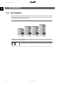
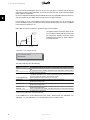
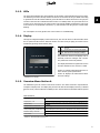
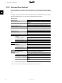
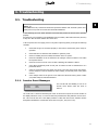
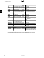
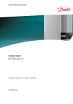
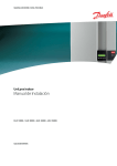
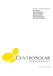
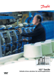
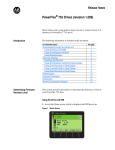
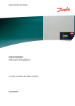
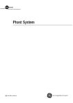
MAKING MODERN LIVING POSSIBLE
UniLynx Indoor
User Manual
ULX 1800i • ULX 3000i • ULX 3600i • ULX 5400i
SOLAR INVERTERS
Contents
Contents
1. Introduction
2
Introduction
2
2. Function Description
3
Definition of Operation Modes
3
PV Configuration
3
LEDs
5
Display
5
Overview Menu Section A
5
Overview Menu Section B
6
3. Troubleshooting
9
Troubleshooting
9
Inverter Event Messages
9
4. Maintenance
11
Maintenance
11
Cleaning the Cabinet
11
Cleaning the Heatsink
11
L00410292-05_02
1
1. Introduction
1
1. Introduction
1.1. Introduction
This manual describes Danfoss photovoltaic inverters. These products are among the most technologically advanced and efficient inverters on the market and are designed to supply the owner
with reliable solar energy for many years.
Illustration 1.1: ULX Indoor Range
CE marking - This certifies the conformity of the equipment with the regulations which apply in accordance with the directives 2004/108/EC and 2006/95/
EC.
2
L00410292-05_02
2. Function Description
2. Function Description
2
2.1. Definition of Operation Modes
The inverter has four modes:
Standby mode:
In standby mode, the inverter is ready to switch into connecting mode. As decision variable the
input voltage of the PV generator is used. If the input voltage exceeds a preset nominal value,
the inverter shifts from “standby” to “connecting”, or continues into the operation mode “OFF” if
the PV voltage drops.
Connecting mode:
After performing the system tests, which check whether all connection conditions are met, the
inverter goes from standby mode to connecting mode. During the specified cut-in time, the inverter continues testing the system values and connects the inverter to the grid if the system tests
are okay. The minimum cut-in time is specified by the supplier and authorities and can vary from
region to region.
Grid mode:
In this mode, the inverter is connected to the grid and supplies power to the grid. The inverter is
only uncoupled from the grid in case of abnormal grid conditions or when PV power is not available.
PV configuration mode
Having completed the connecting mode the PV module wiring is automatically tested to detect
whether any of the DC inputs are wired in parallel string configuration. If so, the DC modules are
automatically run in parallel string configuration mode (Master/Slave).
Derating temperature
If the display shows (DRT. TEMP), the inverter is derating due to high temperatures.
Derating grid
If the display shows (DRT GRID), the inverter is derating due to high voltage on the grid.
Off:
If there is no PV power available, the inverter waits ten minutes (specified value) before it disengages. In this mode, the power supply to all processors is switched off to conserve energy. This
is the normal night mode.
2.1.1. Grid Surveillance
In order to safeguard the people working on AC power lines and the inverter, the inverter shuts
down in the event of abnormal grid conditions or failures. The inverter continuously monitors grid
voltage and frequency by means of an internal control circuit. Subsequently, the inverter will reconnect as soon as the grid is within limits.
2.1.2. PV Configuration
Upon connecting to grid an automatic test of the PV module wiring is performed by the inverter.
This test is made in order to determine the wiring configuration of the modules. It is established
whether the modules are connected in individual string configuration or in parallel string configuration and the inverter is automatically configured accordingly.
L00410292-05_02
3
2. Function Description
The test works by activating the input one by one. The test takes 1-2 minutes and the inverter
continues to produce energy meanwhile. In menu B the result of the test can be read in the display
menu called PV configuration.
Upon test completion the display will automatically show the PV configuration detected; however,
only if the buttons on the display have not been used in the past 3 minutes.
2
For ULX 5400i, 2 out of 3 DC modules must be powered for the test to run. If not enough PV
power is available to power 2 modules, the test is postponed until sufficient PV power is available
for the second DC module to run.
Notice that the inverter continues to produce energy in the meantime.
The display readout shows the status of the
test. The first line shows that this concerns the
PV configuration and the second line shows
which status the test is in or which configuration it has detected.
DC3
+
DC1
DC2
DC2
+
+
DC1
DC1
t
On Grid
Test end
Illustration 2.1: PV configuration test
PV configuration
INDIVIDUAL
The status field may show the following:
Display Text
IDLE
OFF
WAITING
PV-AUTODETECTING
INDIVIDUAL
PARALLEL 1-2*
PARALLEL 1-3*
PARALLEL 2-3*
PARALLEL 1-2-3
Description
PV configuration test has not yet been run. Shown before the inverter connects to
grid.
PV configuration test is disabled. Applicable to ULX 1800i and to inverters where
the test is otherwise disabled.
The PV configuration test is ready to run, but only solar radiation for one PV input
is available. (Applicable to ULX 5400i). The inverter can only determine the configuration of all three modules, when two are running.
The PV configuration test is running. No result yet.
The PV modules are connected in individual string configuration
The PV configuration has ended, concluding that inputs 1 and 2 are connected in
parallel string configuration.
The PV configuration has ended, concluding that inputs 1 and 3 are connected in
parallel string configuration.
The PV configuration has ended, concluding that inputs 2 and 3 are connected in
parallel string configuration.
The PV configuration has ended, concluding that inputs 1, 2 and 3 are connected
in parallel string configuration.
Table 2.1: PV Configuration Test Status Field Text
*) The “PARALLEL 1-2” is only allowed for the ULX 3000i / 3600i inverter. The “PARALLEL 1-2”,
“PARALLEL 1-3”, and “PARALLEL 2-3” is not allowed for the ULX 5400i inverter.
4
L00410292-05_02
2. Function Description
2.1.3. LEDs
The green LED indicators show the production in percentage of the nominal inverter power rating.
The leftmost green LED is always lit when the inverter is connected to the grid. While connecting
to grid both the red LED and the leftmost green LED will be on. When the inverter is off grid, the
red LED to the left is lit to indicate that the inverter is in standby mode. No green LEDs are lit. If
no LED’s are on the inverter is off. If the inverter is forced into standby mode because of an event
in the inverter or the peripheral connections, e.g. disconnection from the grid, the red LED starts
flashing.
2
For a description of events, please refer to the section on Troubleshooting.
2.1.4. Display
Through the integrated display on the inverter front, the user has access to all information about
the PV system and the inverter. When the inverter is in OFF mode (at night), the inverter can be
activated by pressing the left button (ESC).
Goes one step backwards/up in the menu
structure
▲ Up
Scrolls back to the previous menu display
▼ Down Scrolls forward to the next menu display
OK Enter New menu level or changing of settings
θ
ESC
The parameters shown in the display refer to
internally measured voltages and currents.
The parameters shown may deviate.
The display information is organised in a menu
structure divided into two sections: A and B
Section A: Contains information about the inverter and PV system performance.
Section B: Displays all measurement values
and user settings.
Illustration 2.2: Display
2.1.5. Overview Menu Section A
The table below gives an overview of the menu structure. The values shown are only intended as
examples of display texts. The display text (shown in the first column Display Functions ) is divided
between 2 lines, with 16 characters available per line. The line division is illustrated with the symbol
|.
Menu Structure A
Display Functions
Description
Output power | 0 W
Current output power in watt.
Inverter name |
Use Service Tool to enter inverter name. If the inverter name is undefined this menu
is skipped.
Total production | 22.991 kWh
Total energy production in kWh since first inverter start-up.
Total operating time | 00028h 57m 02s Total operating time (time with power on) displayed in hours, minutes and seconds.
Production today | 19637 Wh
Energy production today in Wh.
Go to menu B
Jumps to menu level B when OK is pressed.
Table 2.2: Overview Menu Structure A
L00410292-05_02
5
2. Function Description
2.1.6. Overview Menu Section B
The table below gives an overview of the menu structure. The two menu levels are clearly indicated
by an arrow followed by a submenu. The values shown are only intended as examples of display
texts.
2
The display text (shown in the first column Display Functions ) is divided between 2 lines, with 16
characters available per line. The line division is illustrated with the symbol |.
Menu Structure B
Display Functions
Operation mode | STANDBY
PV configuration | IDLE
Event: Mod. | ENS FL. CH DCAC
Description
Displays present inverter operation mode. See operation mode definitions
in chapter 2.
Shows the status of the automatic PV configuration test and the results
found.
If the inverter is not connected to the grid because of a failure, the red
LED starts flashing, and the reason for the failure is shown here.
Language | ENGLISH
View and choose display language. Does not affect any other settings.
Grid voltage | 0 V
Displays the present grid AC voltage.
Grid current | 0.00 A
Displays the present current flow to the grid.
Grid frequency | 0.00 Hz
Displays the present grid frequency.
Grid impedance | 0.0 ohm
Displays the present grid impedance.
PV voltage | Press OK to view
Press OK to access submenu for recorded values.
↳
Submenu
PV voltage no. 1 | 303.0 V
Present voltage at PV input 1 (upper position in inverter).
PV voltage no. 2 | 303.0 V
Present voltage at PV input 2 (second position in inverter)*.
PV voltage no. 3 | 303.0 V
Present voltage at PV input 3 (third position in inverter)*.
PV current | PRESS OK to view
↳
Submenu
PV current no. 1 | 0.0 A
Present current at PV input 1 (upper position in inverter).
PV current no. 2 | 0.0 A
Present current at PV input 2 (second position in inverter)*.
PV current no. 3 | 0.0 A
Present current at PV input 3 (third position in inverter)*.
Maximum values | Press OK to view
↳
Press OK to access submenu for recorded values.
Press OK to access submenu for recorded values.
Submenu
Maximum values recorded at AC output since last resetting of max. value
memory.
Maximum values recorded at DC1 input since last resetting of max. value
DC1 in: 2220 W** | 8.004 A 509 V
memory.
Maximum values recorded at DC2* input since last resetting of max. value
DC2 in: 2220 W** | 8.004 A 509 V
memory.
Maximum values recorded at DC3* input since last resetting of max. value
DC3 in: 2220 W** | 8.004 A 509 V
memory.
AC out: 1844 W | 8.356 A 263 V
Table 2.3: Overview Menu Structure B
*) The PV2 and PV3 menus are only displayed in inverters equipped with two or three inputs.
6
L00410292-05_02
2. Function Description
Menu Structure B- Continued
Display Functions
Description
Maximum values | Press OK to view
Press OK to access submenu for recorded values.
↳
2
Submenu
Maximum values recorded at AC output since last resetting of max. value
memory.
Maximum values recorded at DC1 input since last resetting of max. value
DC1 in: 2220 W** | 8.004 A 509 V
memory.
Maximum values recorded at DC2* input since last resetting of max. value
DC2 in: 2220 W** | 8.004 A 509 V
memory.
Maximum values recorded at DC3* input since last resetting of max. value
DC3 in: 2220 W** | 8.004 A 509 V
memory.
AC out: 1844 W | 8.356 A 263 V
Total Derating Temperature. Shows the total amount of time the inverter
has derated due to high temperature.
Total drt. Temp. - Press OK to view
↳
Submenu
DC1 Derating Temperature. Shows the amount of time the inverter has
derated due to high temperature.
DC2* Derating Temperature. Shows the amount of time the inverter has
derated due to high temperature.
DC3* Derating Temperature. Shows the amount of time the inverter has
derated due to high temperature.
DC1 derate temp. | 3h 35m
DC2 derate temp. | 3h 35m
DC3 derate temp. | 3h 35m
Total Derating Grid. Shows the amount of time the inverter has derated
due to unstable grid conditions.
Time before inverter goes into ‘OFF’ mode when no solar power is available.
Total drt. Grid | 0h 00 min
Power-down time | 00600 seconds
Code numbers | PRESS OK to view
↳
Press OK to access submenu for recorded values.
Submenu
Inverter code no. |
Indicates inverter product code.
AC code number | C0070105602
Indicates AC module product code.
DC1 code number | C0070105402 Indicates DC1 module product code.
DC2 code number | C0070105402 Indicates DC2* module product code.
DC3 code number | C0070105402 Indicates DC3* module product code.
Serial numbers | Press OK to view
↳
Press OK to go to submenu for recorded values.
Submenu
Inverter SN: |
Indicates inverter serial number.
AC SN: | 117500C0408
Indicates AC module serial number.
DC1 SN: | 642800C0808
Indicates DC1 module serial number.
DC2 SN: | 642800C0808
Indicates DC2* module serial number.
DC3 SN: | 642800C0808
Indicates DC3* module serial number.
Table 2.4: Overview Menu Structure B
*) The DC2 and DC3 menus are only displayed in inverters equipped with two or three inputs.
**) The maximum values for PV power may reach more than 2000 W in inverters where the inputs are connected in parallel.
This is normal.
In menu section A the display will continue to show the menu point last chosen by the user.
In menu B the display automatically switches to menu A when there has been no keyboard activity
for 3 minutes.
L00410292-05_02
7
2. Function Description
If the inverter is off grid and no keys have been pressed for a certain number of seconds, the
display will automatically switch to the operation mode display.
If the inverter is on grid and there has been no keyboard activity for 3 minutes, the display automatically switches to the display Production today. When the PV configuration test initiates and
terminates the display temporarily changes to menu B to show the state of the PV configuration
test.
2
If the inverter is disconnected from the grid because of a failure, the red LED will start flashing,
and the display automatically switches to menu B, where the event is shown.
If an earthing fault occurs, the display will indicate this by a flash of the lit green LEDs. The display
will change to “current event”, if it has not been operated in the past 10 minutes. The inverter
will continue to produce energy. In case an earth fault occurs, this does not indicate an inverter
error and technical assistance must be called to check the PV panel connection.
Only applicable if earth fault detection is enabled. By default, earth fault detection is enabled for
the following countries: Austria, France and Spain.
8
L00410292-05_02
3. Troubleshooting
3. Troubleshooting
3.1. Troubleshooting
3
Note:
Remember that only trained and authorised personnel familiar with electrical systems and
safety issues may work on inverters and electrical installations.
In the following, the term 'Event' describes all events that prevent the inverter from operating
properly.
An event may occur anywhere in the installation (grid, PV module, cable and connections, inverter)
at any time. Not all events indicate an inverter error.
If the PV system does not supply power to the grid as expected, please go through the following
checklist:
1.
Check that the grid is connected properly to the inverter and that the grid is ready for
operation.
2.
Check that there is sufficient solar radiation to generate power.
3.
Check for shading and loose cables/connections in the PV system.
4.
Check the installation of the PV modules if the voltages of the PV modules is not within
the expected values.
5.
Check the event in menu B. If the red LED is flashing, this indicates a failure.
6.
If the above-mentioned points are OK, wait 15 minutes to find out whether there is a
permanent failure.
7.
If the PV system still does not supply any power to the grid, please check the voltage,
current and power of the PV module as well as voltage, current and power of the grid in
menu B.
8.
If the voltage values of the grid do not lie within the threshold values, please contact
your public utility for technical assistance.
3.1.1. Inverter Event Messages
Event:
U-GRID
The red LED will start flashing in case of an
inverter event. Please check the event in
menu B.
Mod.
DCAC
The event text is a short text describing the event. If the inverter reports an event ID number to
the display instead of a text, no event text has been predefined for that particular event ID number. This could be the case if the display software is older than the inverter software. Module
designation identifies the module that caused the event (DC1, DC2, DC3 or AC).
L00410292-05_02
9
3. Troubleshooting
3
Event text
Description
U 3.3
U 5.0
U 15.0
U PV
Internal power supply outside limits
Internal power supply outside limits
Internal power supply outside limits
Input voltage from PV string too high
U-SNUBBER
U DC-BUS
U-GRID
Snubber voltage too high
DC bus voltage too high
AC grid voltage outside the threshold
values (higher or lower than setting)
Grid frequency outside limits (outside
settings)
The DC content in the AC current is too
high
ENS error
Inverter
Inverter
AC grid
ENS RAM
ENS FL. CHKSM
ENS EP. CHKSM
HW TRIP
TEMP HIGH
ENS memory error
Flash memory error after self-test
EPROM memory error after self-test
Hardware trip – current too high
Temperature in integrated power module too high
Inverter
Inverter
Inverter
Inverter
Environment
EPRM PAR. LIM
ENS COM ERR
ENS impedance
Validity check of grid voltage and fre- Inverter
quency settings. Settings too far away
from actual grid voltage and frequency
values.
Error in communication with ENS board Inverter
Grid impedance step higher than limit AC grid
PV—CONFIG—ERR
Error detected by PV configuration test PV system
F-GRID
IPM CURRENT
ENS
Not recorded in the event log - red LED does not flash
Event text
Description
EARTHFAULT
Current event shown in grid mode
Fault
origin
Inverter
Inverter
Inverter
PV system
AC grid
Inverter
AC grid
Fault
origin
PV system
Action in the event of a permanent failure
Service inverter
Service inverter
Service inverter
Request technical service from PV system
supplier
Service inverter
Service inverter
In case of repeated occurrence: Request
technical service from utility
In case of repeated occurrence: Request
technical service from utility
Service inverter
In case of repeated occurrence: Request
technical service from utility
Service inverter
Service inverter
Service inverter
Service inverter
Check whether inverter is covered.
Check inverter for free air flow through heat
sink. Clean heat sink.
Check that ambient temperature is within
limits.
Request service to check inverter settings
Service inverter
In case of repeated occurrence: Request
technical service from utility
Check the cabling of the PV panels. Two DC
inputs are wired in parallel string configuration, one is not
Action in the event of a permanent failure
Earth fault, check PV system for earthing to
avoid damage to PV panels. Request technical service from the PV system supplier or installer.
Table 3.1: Inverter Event Log
A “permanent failure” is defined by an event having been present for more than 15 minutes.
10
L00410292-05_02
4. Maintenance
4. Maintenance
4.1. Maintenance
4.1.1. Maintenance
Normally, the ULX indoor inverters need no maintenance or calibration. It should be ensured,
however, that the cooling is not obstructed and that the inverter is kept dry at all times.
4
To ensure the functionality of the DC-switch, all switches should be switched on and off (by turning
the switch to on and off positions ten times) once a year, to clean the contacts.
If it becomes wet, wipe it dry immediately. Liquids may contain substances that corrode the electronics.
4.1.2. Cleaning the Cabinet
Clean inverter and integrated display with a soft cloth. Do not use aggressive chemicals, cleaning
solvents or strong detergents to clean the inverter.
4.1.3. Cleaning the Heatsink
In order to secure proper function and long inverter life, it is essential that the free air circulation
around the heat sink at the back of the inverter is not obstructed.
If the free air circulation is obstructed, e.g. by dust, this has to be removed. Clean the heatsink
by means of a soft cloth or a brush. Do not use aggressive chemicals, cleaning solvents or strong
detergents to clean the inverter.
The heatsink can reach a temperature of more than 70 °C during operation. Touching components of this temperature may result in serious injuries!
Note:
Do not cover the inverter.
L00410292-05_02
11
Danfoss Solar Inverters A/S
Ulsnaes 1
DK-6300 Graasten
Denmark
Tel: +45 7488 1300
Fax: +45 7488 1301
E-mail: [email protected]
www.solar-inverters.danfoss.com
Danfoss can accept no responsibility for possible errors in catalogues, brochures and other printed material. Danfoss reserves the right to alter its products without notice. This also applies to products
already on order provided that such alterations can be made without subsequential changes being necessary in specifications already agreed.
All trademarks in this material are property of the respective companies. Danfoss and the Danfoss logotype are trademarks of Danfoss A/S. All rights reserved.
Rev. date 2010-03-24 Lit. No. L004100292-05_02