1
Emotron TSA
Softstarter
Instruction manual
English
Software version 1.0X
Emotron TSA softstarter
INSTRUCTION MANUAL - ENGLISH
Software version 1.0X
Document number: 01-5980-01
Edition: R0
Date of release: 13-05-2013
© Copyright CG Drives & Automation Sweden AB 2013
CG Drives & Automation Sweden AB retains the right to change
specifications and illustrations in the text, without prior notification.
The contents of this document may not be copied without the explicit
permission of CG Drives & Automation Sweden AB.
Safety instructions
Congratulations for choosing a product from CG Drives &
Automation!
Before you begin with the installation, commissioning or
powering up the unit for the first time it is very important
that you carefully study this instruction manual.
The following symbols can appear in this manual or on the
product itself. Always read these first before continuing.
NOTE: Additional information as an aid to avoid
problems.
!
CAUTION!
Failure to follow these instructions can result
in malfunction or damage to the softstarter.
WARNING!
Failure to follow these instructions can result
in serious injury to the user in addition to
serious damage to the softstarter.
Phase compensation capacitor
If a phase compensation capacitor is to be used, it must be
connected at the inlet of the softstarter, not between the
motor and the softstarter.
Installation of spare parts
We expressly point out that any spare parts and accessories
not supplied by us have also not been tested or approved by
us.
Installing and/or using such products can have a negative
effect on the characteristics designed for your device. The
manufacturer is not liable for damage arising as a result of
using non-original parts and accessories.
Emergency
You can switch the device off at any time with the mains
switch connected before the softstarter (both motor and
control supply voltage must be switched off ).
General warnings
Safety
WARNING!
Make sure that all safety measures have
been taken before starting the motor in order
to avoid personal injury.
The softstarter should be installed in a cabinet or in an
electrical control room.
• The device must be installed by trained personnel.
•
Disconnect all power sources before servicing.
•
Always use standard commercial fuses, slow blow e.g.
gl, gG types, to protect the wiring and prevent short
circuiting. To protect the thyristors against short-circuit
currents, superfast semiconductor fuses can be used if
preferred. The normal guarantee is valid even if superfast
semiconductor fuses are not used.
Operating and maintenance
personnel
1. Read the whole instruction manual before installing and
putting the equipment into operation.
2. During all work (operation, maintenance, repairs, etc.)
observe the switch-off procedures given in this
instruction as well as any other operating instruction for
the driven machine or system. See Emergency below.
3. The operator must avoid any working methods which
reduce the safety of the device.
4. The operator must do what he can to ensure that no
unauthorised person is working on the device.
5. The operator must immediately report any changes to
the device which reduce its safety to the user.
6. The user must undertake all necessary measures to
operate the device in perfect condition only.
CG Drives & Automation 01-5980-01r0
WARNING!
Never operate the softstarter with the front
cover removed.
WARNING!
Make sure that all safety measures have
been taken before switching on the power
supply.
Alarms
Never disregard an alarm. Always check and remedy the
cause of an alarm.
1
2
CG Drives & Automation 01-5980-01r0
Contents
Safety instructions ......................................... 1
Contents .......................................................... 3
5.3
5.4
5.5
Default toggle loop.................................................. 30
Remote I/O operation ............................................. 30
Control panel operation .......................................... 31
1.
Introduction..................................................... 5
6.
Operation via the control panel .................. 33
1.1
1.2
1.3
1.4
1.5
1.5.1
1.6
1.6.1
1.7
1.7.1
1.7.2
Delivery and unpacking ............................................
Using of the instruction manual...............................
Warranty ....................................................................
Type code number.....................................................
Standards ..................................................................
Product standard for EMC ........................................
Dismantling and scrapping.......................................
Disposal of old electrical and electronic
equipment .................................................................
Glossary .....................................................................
Abbreviations and symbols.......................................
Definitions..................................................................
6.1
6.2
6.3
6.4
6.4.1
6.4.2
6.5
6.5.1
6.5.2
6.6
6.6.1
Display .....................................................................
LED indicators .........................................................
Control keys.............................................................
Function keys ..........................................................
+/- key function.......................................................
Jog key function.......................................................
Toggle and Loc/Rem Key .......................................
Toggle function........................................................
Loc/Rem function ...................................................
The menu structure ................................................
The main menu .......................................................
2.
Mounting ......................................................... 9
2.1
2.1.1
2.1.2
Installation in a cabinet ............................................ 9
Cooling ....................................................................... 9
Mechanical specifications and drawings .............. 10
3.
Connections ................................................. 11
3.1
3.2
3.3
3.4
Mains and motor connections ...............................
Board layout and connectors .................................
Control signal connections .....................................
Wiring examples ......................................................
4.
Application guidelines ................................ 21
4.1
4.2
4.3
4.4
4.4.1
4.4.2
4.4.3
4.4.5
4.4.6
4.4.7
4.4.8
4.4.9
4.4.10
4.4.11
4.4.12
4.4.13
Softstarter dimensioning according to AC-53b .....
Applications rating ..................................................
The Application Functions List ...............................
Special conditions...................................................
Small motor or low load..........................................
Ambient temperature below 0°C...........................
Pump control with softstarter and AC drive
together ...................................................................
Starting with counter-clockwise (reverse) rotating
loads.........................................................................
Running motors connected in parallel...................
Running motors linked together ............................
Heat dissipation in cabinets...................................
Insulation test on motor .........................................
Operation above 1,000 m ......................................
Aggressive environment conditions .......................
IT earthing system...................................................
Earth fault relay.......................................................
Other control voltage ..............................................
5.
Getting started............................................. 29
5.1
5.2
5.2.1
5.2.2
5.2.3
Check list .................................................................
Mains and motor connection .................................
Connect the mains cables ......................................
Connect the motor cables ......................................
Connect the control supply voltage........................
4.4.4
CG Drives & Automation 01-5980-01r0
5
5
5
5
6
6
6
6
7
7
7
12
14
15
16
21
21
23
26
26
26
26
26
26
26
26
26
26
26
26
27
27
29
29
29
29
29
33
34
34
34
35
35
35
35
36
37
37
7.
Main features ............................................... 39
7.1
7.1.1
7.1.2
7.1.3
7.1.4
7.1.5
7.1.6
7.2
7.2.1
7.2.2
7.2.3
7.2.4
7.3
7.3.1
7.3.2
7.3.3
7.3.4
7.3.5
7.4
7.5
7.6
7.6.1
7.6.2
7.6.3
Setting Start, Stop and Run functions ...................
Start and stop control .............................................
Start and stop methods..........................................
Jog functions ...........................................................
Start/Stop signal priority ........................................
Setting motor data ..................................................
Process information................................................
Working with parameter sets .................................
Control of parameter sets ......................................
Configuration of parameter sets ............................
Handling motor data in parameter sets ................
Using the control panel memory ............................
Applying limitations, alarms and autoreset...........
Alarm types and actions .........................................
Alarm settings..........................................................
Alarm indications ....................................................
Load monitor function ............................................
Reset and autoreset ...............................................
Programmable I/O ..................................................
Logical functions .....................................................
Remote control functions .......................................
Default settings of the Run/Stop/Reset
functions ..................................................................
Enable and Stop functions .....................................
Reset and Autoreset operation ..............................
8.
Functionality................................................. 55
8.1
8.1.1
8.1.2
8.2
8.2.1
8.2.2
8.2.3
8.2.4
8.2.5
8.2.6
Preferred View [100]...............................................
1st Line [110]..........................................................
2nd Line [120] ........................................................
Main Setup [200]....................................................
Operation setup [210] ............................................
Remote signal Level/Edge [21A] ...........................
Motor Data [220] ....................................................
Motor protection [230] ...........................................
Parameter set handling [240]................................
Autoreset [250] .......................................................
39
39
39
40
40
40
40
41
41
42
42
42
45
45
45
45
46
50
51
51
51
51
52
52
56
57
57
57
57
60
60
62
66
69
3
8.2.7
8.3
8.3.1
8.3.2
8.3.3
8.3.4
8.3.5
8.4
8.4.1
8.4.2
8.4.3
8.5
8.5.1
8.5.2
8.5.3
8.5.4
8.5.5
8.6
8.6.1
8.6.2
8.6.3
8.6.4
8.6.5
8.6.6
8.7
8.7.1
8.7.2
8.7.3
8.7.4
8.8
8.8.1
8.8.2
8.8.3
8.9
8.9.1
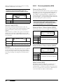
Serial Communication [260] .................................. 73
Process [300] .......................................................... 76
View Process Value [310]....................................... 76
Process Settings [320] ........................................... 76
Start setting [330]................................................... 78
Stop Setting [340]................................................... 80
Jog [350].................................................................. 83
Load Monitor and Process Protection [400] ......... 84
Load Monitor [410]................................................. 84
Process protection [420]........................................ 88
Mains Protection [430]........................................... 89
I/O [500].................................................................. 91
Analogue Input [510] .............................................. 91
Digital Inputs [520] ................................................. 94
Analogue Output [530] ........................................... 95
Relays [550] ............................................................ 97
Virtual I/Os [560] .................................................... 99
Logical Functions and Timers [600] .................... 100
Comparators [610] ............................................... 100
Logic outputs [620]............................................... 105
Timers [630].......................................................... 109
SR Flip-flops [640] ................................................ 110
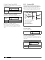
Counters [650] ...................................................... 112
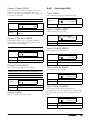
Clock Logic [660] .................................................. 113
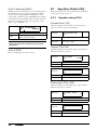
Operation/Status [700] ........................................ 114
Operation values [710]......................................... 114
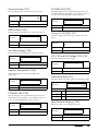
Status [720] .......................................................... 116
Stored Values [730].............................................. 119
Real time clock settings [740] ............................. 119
View Trip Log [800] ............................................... 120
Trip Message Log [810]........................................ 120
Trip Messages [820] - [890]................................. 121
Reset Trip Log [8A0] ............................................. 121
System Data [900]................................................ 121
TSA Data [920]...................................................... 121
9.
Serial communication ............................... 123
9.1
9.2
9.3
9.4
9.5
9.6
Modbus RTU .......................................................... 123
Parameter sets...................................................... 123
Motor data ............................................................. 124
Start and stop commands .................................... 124
Process value ........................................................ 124
Description of the EInt formats ............................ 125
10.
Softstarter theory ...................................... 127
10.1
10.2
10.3
10.4
Background theory................................................ 127
Reduced voltage starting...................................... 128
Other starting methods......................................... 130
Use of softstarters with torque control ................ 132
11.
Troubleshooting, Diagnoses and
Maintenance.............................................. 133
11.1
11.1.1
11.1.2
11.2
11.3
Trip conditions, causes and remedial action ...... 133
Technically qualified personnel............................ 133
Opening the softstarter......................................... 133
Maintenance ......................................................... 133
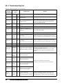
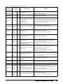
Troubleshooting list............................................... 134
4
12.
Options........................................................ 137
12.1
12.2
12.3
12.4
12.5
External control panel........................................... 137
EmoSoftCom.......................................................... 137
I/O Board ............................................................... 137
PTC/PT100 ............................................................ 137
Serial communication and fieldbus ..................... 137
13.
Technical data............................................ 139
13.1
13.2
13.3
13.3.1
13.3.2
13.4
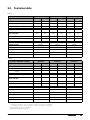
General electrical specifications.......................... 141
Semi-conductor fuses ........................................... 141
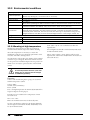
Environmental conditions..................................... 142
Derating at high temperature............................... 142
Derating at high altitude....................................... 143
Control power- and I/O signal connectors........... 144
Index ........................................................... 145
Appendix 1: Menu List ............................... 147
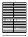
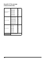
Appendix 2: Trip message communication data 164
CG Drives & Automation 01-5980-01r0
1.
Introduction
The Emotron TSA softstarter is intended for controlling the
start and stop of standard three phase asynchronous motors.
A built-in powerful digital signal processor (DSP) gives the
softstarter high performance and very good control of the
starting and stopping of the application.
Several options are available, listed in chapter 12. page 137,
that enable you to customize the softstarter for your specific
needs.
NOTE: Read this instruction manual carefully before
installing, connecting or working with the softstarter.
1.3
Warranty
The warranty applies when the equipment is installed,
operated and maintained according to instructions in this
instruction manual. Duration of warranty is as per contract.
Faults that arise due to faulty installation or operation are
not covered by the warranty.
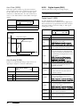
1.4
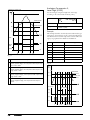
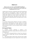
Type code number
Fig. 1 gives an example of the type code numbering used for
the Emotron TSA softstarter. This identification will be
required for type specific information when mounting and
installing. The code number is located on the product label,
on the right side of the unit (when viewed from the front).
TSA 52 -016 -23 N N N — A A —
Users
This instruction manual is intended for:
•
installation engineers
•
maintenance engineers
•
operators
•
service engineers
Position number:
1
2
Fig. 1
3
4
5
6
7
8
9 10 11
Type code number
Table 1
Position Configuration
Description
Motors
1
Type
TSA
The softstarter is suitable for use with standard 3-phase
asynchronous motors. Contact your supplier for details.
2
Main supply voltage
52 = Max 525 V mains
69 = Max 690 V mains
1.1
3
Current rating
016 = 16 A
- 1K8 = 1800 A
4
Control voltage
23=230 V
Check that all items are present and that the type number is
correct.
5
Option position 1
N=No option
P=PTC/PT100
I=I/O board
1.2
6
Option position 2
N=No option
P=PTC/PT100
I=I/O board
7
Communication
option
N=No option
A=Profinet IO 1-port
B=Profinet IO 2-port
D=DeviceNet
M=Modbus/TCP
P=Profibus
R=RS485
U=USB
8
IT-net option
9
Brand label
A=Standard
10
Software
A=Standard software
11
Standard
— =CE approved
Delivery and unpacking
Check for any visible signs of damage. Inform your supplier
immediately of any damage found. Do not install the
softstarter if damaged.
Using of the instruction
manual
Check that the software version number on the first page of
this manual matches the software version in the softstarter.
See chapter 8.9.1 page 121.
With help of the index and the table of contents it is easy to
track individual functions and find out how to use and set
them.
The Quick Start Guide can be put in a cabinet so that it is
always easy to access in case of an emergency.
CG Drives & Automation 01-5980-01r0
— =No option
I=IT-net
Introduction
5
1.5
Standards
1.5.1 Product standard for EMC
The softstarters described in this instruction manual comply
with the standards listed in Table 2. For the declarations of
conformity and manufacturer’s certificate, contact your
supplier for more information or visit www.emotron.com or
www.cgglobal.com.
Table 2
Standards
Market
European
All
USA
1.6
Standard
Description
EMC Directive
2004/108/EC
Low Voltage Directive
2006/95/EC
WEEE Directive
2002/96/EC
EN 60204-1
Safety of machinery - Electrical equipment of machines
Part 1: General requirements.
EN(IEC)60947-4-2:
2007
Contactors and motor starters
Part 3: EMC requirements and specific test methods.
EMC Directive: Declaration of Conformity and CE marking
EN(IEC)60947-4-2:
2007
Contactors and motor starters
Safety requirements - Electrical, thermal and energy.
Low Voltage Directive: Declaration of Conformity and CE marking
IEC 60721-3-3
Classification of environmental conditions. Air quality chemical vapours, unit in
operation. Chemical gases 3C3, Solid particles 3S1.
UL508C
UL Safety standard for Power Conversion Equipment. Pending.
UL 840
UL Safety standard for Power Conversion Equipment. Pending.
Dismantling and scrapping
The enclosures of the Emotron TSA softstarters are made
from recyclable material such as aluminium, iron and
plastic. Each softstarter contains a number of components
demanding special treatment. The circuit boards contain
small amounts of tin and lead. Any local or national
regulations in force for the disposal and recycling of these
materials must be complied with.
6
The Emotron TSA softstarter complies with the product
standard EN(IEC) 60947-4-2: 2007. The standard
Emotron TSA softstarter is designed to meet the EMC
requirements according to category C1.
Introduction
1.6.1 Disposal of old electrical and
electronic equipment
This symbol on the product or on its packaging indicates
that this product shall be taken to the applicable collection
point for the recycling of electrical and electronic
equipment. By ensuring this product is disposed of correctly,
you will help prevent potentially negative consequences for
the environment and human health, which could otherwise
be caused by inappropriate waste handling of this product.
The recycling of materials will help to conserve natural
resources. For more detailed information about recycling
this product, please contact the local distributor of the
product.
CG Drives & Automation 01-5980-01r0
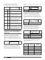
1.7
Glossary
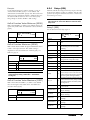
1.7.2 Definitions
In this manual the following definitions are used:
1.7.1 Abbreviations and symbols
Table 4
In this manual the following abbreviations are used:
Table 3
Abbreviations
Abbreviation/
symbol
Description
CP
Control panel, the programming and
presentation unit on the softstarter
CB
Control board
I2
The amount of energy losses, heating up the
motor.
PTC
Positive Temperature Coefficient
(temperature sensor, also known as
thermistor)
PB-PTC
Power board PTC input
RMS
Root Mean Square value
FLC
Full Load Current
DOL
Direct On-Line
EInt
Communication format
UInt
Communication format (Unsigned Integer)
Int
Communication format (Integer)
Long
Communication format (Integer Long)
t
Name
Definitions
Description
Unit
In_soft
Nominal softstarter current
[Arms]
In_mot
Nominal motor current
[Arms]
Pn_soft
Nominal softstarter power
[kW] or [hp]
Pn_mot
Nominal motor power
[kW] or [hp]
Tn
Nominal motor torque*
[Nm] or [lb.ft]
nn_mot
Nominal speed of motor
[rpm]
cosn
Nominal motor power factor
(dimensionless)
U
3-phase mains supply voltage
[Vrms]
Un_mot
Nominal motor voltage
[V]
*) Calculation of nominal motor torque:
9550 P n mot kW
T n Nm = ----------------------------------------------n n mot rpm
5252 P n mot hp
T n lb ft = ---------------------------------------------n n mot rpm
The function cannot be changed in run mode
CG Drives & Automation 01-5980-01r0
Introduction
7
8
Introduction
CG Drives & Automation 01-5980-01r0
2.
Mounting
This chapter describes how to mount the Emotron TSA
softstarter. Before mounting it is recommended that the
installation is planned out:
•
Be sure that the softstarter suits the mounting location.
•
The mounting site must support the weight of the
softstarter.
•
Will the softstarter continuously withstand vibrations
and/or shocks?
•
Consider using a vibration damper.
•
Check ambient conditions, ratings, required cooling air
flow, compatibility of the motor, etc.
•
Do you know how the softstarter will be lifted and
transported?
Make sure that the installation is performed in accordance
with the local safety regulations, and in accordance with
DIN VDE 0100 for setting up power installations.
Care must be taken to ensure that personnel do not come
into contact with live circuit components.
WARNING!
Never operate the softstarter with the front
cover removed.
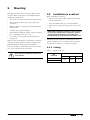
2.1
Installation in a cabinet
When installing the softstarter:
•
Ensure that the cabinet will be sufficiently ventilated
after the installation.
•
Keep the minimum free space, as listed inTable 5.
•
Ensure that air can flow freely from the bottom to the
top.
NOTE: When installing the softstarter, make sure it does
not come into contact with live components. The heat
generated must be dispersed via the cooling fins to
prevent damage to the thyristors (free circulation of air).
The Emotron TSA softstarters are delivered as enclosed
versions with front access cover. The units have top and
bottom entry for cables etc., see Chapter 3. page 11.
2.1.1 Cooling
Table 5
Minimum free space
TSA
Frame size
1
2
Minimum free space (mm):
above*
below
at side
100
100
0
*) Above: Cabinet roof to softstarter or softstarter to softstarter
CG Drives & Automation 01-5980-01r0
Mounting
9
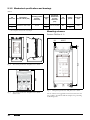
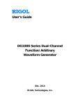
2.1.2 Mechanical specifications and drawings
Table 6
TSA
Frame size
1
2
Dimensions*
H1/H2 x W x D [mm]
Mounting position
[Vertical/
Horizontal]
246/296 x 126 x 188
Vertical
Connection
busbars and
pressnut
dimension
[mm]
PE
screw
15 x 4, Cu (M6)
M5
Weight
[kg]
5.5
5.7
Cooling
system
Convection
Fan
Protection
class
IP20
Mounting schemes
*) H1 = Height of enclosure, H2 = Total height
Emotron TSA Size 1 - 2
11
104.5
11
H1
H2
Ø 6,5 (x 4)
126
273
Fig. 2
188
Dimensions for Emotron TSA frame size 1 and 2.
188
Fig. 4
Fig. 3
10
Dimensions for Emotron TSA frame size 1 and 2,
bottom view.
Mounting
Hole pattern for Emotron TSA frame size 1 and 2.
On our websites www.cgglobal.com and www.emotron.com
it is possible to download a full-size template for positioning
of the fixing holes.
CG Drives & Automation 01-5980-01r0
3.
Connections
The installation description in this chapter follows the EMC
standards and the Machinery Directive.
If the softstarter is temporarily stored before being
connected, please check the technical data for environmental
conditions section 13.3, page 142. If the softstarter is moved
from a cold storage room to the location where it is to be
installed, condensation could appear on the unit. Allow the
softstarter to become fully acclimatised and wait until any
visible condensation has evaporated before connecting any
supply voltages.
Cables
Dimension the mains and motor cables according to local
regulations and the nominal current of the motor.
It is not necessary to use shielded motor cables together with
the Emotron TSA softstarter. This is due to its very low
radiated emissions.
Neither is it necessary to use shielded mains supply cables
for the Emotron TSA softstarter.
For the control connections, it is not necessary to use
shielded control cables, however with the exception of the
option board connections (see section 3.2, page 14) for
which it is recommended to use flexible wire with a braided
type of shield.
NOTE: For the Emotron TSA softstarter it is not
mandatory to use shielded cables to fulfil the EMC
regulations (section 1.5, page 6). The only exception is
when connecting option board cables, for which there is
an earthing plate that serves as an attachment for the
shielded control cables (see Fig. 9 on page 14).
NOTE: For UL-approval use 75°C copper wire only.
CG Drives & Automation 01-5980-01r0
Connections
11
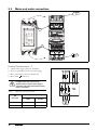
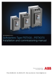
3.1
Mains and motor connections
PE 2
L1
L2
L3
L1
L2
L3
T1
T2
T3
1
3
T1
Fig. 5
T2
T3
4
Mains and motor connections for Emotron TSA Size 1-2.
Emotron TSA frame size 1 - 2
1. 3-phase mains supply connection, L1, L2, L3
100 - 240 VAC
2. Protective earth (PE) connection for mains supply
3. Motor power supply connection T1, T2, T3
4. Motor earth,
connection
WARNING!
Leakage current may occur from the
thyristors when a 3-phase mains supply is
connected. Full voltage can be detected if no
motor is connected.
Table 7
Tightening torque for bolts [Nm].
Tightening torque for bolts [Nm]
TSA
Frame size
Motor or mains
cables
PE cable
1
8
5
2
8
5
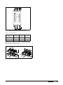
Fig. 6
12
Connections
Mains, motor and control supply voltage connection
CG Drives & Automation 01-5980-01r0
W3 W2 W1
W3 W2 W1
Fig. 7
Table 8
Busbar distances Emotron TSA Size 1 and 2
Busbar distances.
TSA
frame size
Dist. W1
[mm]
Dist.W2
[mm]
Dist.W3
[mm]
1
23
40
40
2
23
40
40
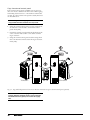
When the Mains and motor cables are connected, mount
the cable covers according to Fig. 8.
Fig. 8
Mount the cable covers.
CG Drives & Automation 01-5980-01r0
Connections
13
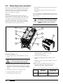
3.2
Board layout and connectors
This section contains general information about the power
board and control board for each Emotron TSA size. For
additional information about special conditions refer to
section 4.4, page 26. For a description of the available
options, go to chapter 12. page 137.
Isolation
The control board in the Emotron TSA product is a
Separated Extra Low Voltage (SELV) circuit. This means
that this board is safely separated from other circuits that
carry higher voltages and is isolated from earth and
protective earth conductors of other circuits. The PTC
circuit on the power board is separated from the control
board SELV circuit with a separation rated for:
•
Double insulation when used in softstarters rated up to
525 VAC.
•
Basic insulation when used in softstarters rated up to
690 VAC.
It is recommended that the PTC/PT100 sensors are always
separated from live parts with at least basic insulation for the
relevant voltage.
WARNING!
For softstarters rated higher than 525 VAC, it
is mandatory to have at least basic insulation
from the temperature sensor towards live
voltage.
5
6
4
7
3
10
8
2
1
Fig. 9
Board layout for Emotron TSA Size 1-2.
Emotron TSA Size 1 - 2
1. Control supply voltage connection PE, N, L (power
board).
WARNING!
For safety reasons the protective earth (PE)
for the control supply must be connected.
2. Earthing plate with slots for tie wraps for fixation and
securing of control signal cables and option board cables.
This plate is connected to earth for earthing of shielded
cables.
3. S1 jumper for U/I selection of analogue input
9
6. LED indicators (visible through perforation):
- Red and blue for communication signals
- Green indicating power on
7. Clock battery, type CR 2032, 3 V
8. Terminals for DigIn/AnIn/AnOut signals (control
board)
9. Terminals for relay output signals and PTC connection
(power board)
10. RS232, using 9-pin female D-sub connector. For
temporary connection of a personal computer or
connection of external control panel (option)
Table 9
TSA size
4. Option board ribbon cable connector
5. Communication module (option)
Control signal cable dimension and stripping lenght
1-2
Max. Cable
dimension
Recommended
stripping length
Flexible: 1.5 mm2
Solid: 2.5 mm2
6 mm*
* When using Ferrules, suitable Ferrule length is 10-12 mm.
14
Connections
CG Drives & Automation 01-5980-01r0
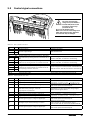
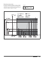
3.3
Control signal connections
WARNING!
The same external supply
voltage level (max 24 VDC or
max 250 VAC) must be used
for all three output relays
(terminals 21-33).
Do not mix AC and DC voltage.
Make sure to use the same voltage level
within this terminal section, otherwise
the softstarter may be damaged.
Fig. 10 Control board and power board connections.
Table 10
Power board connections
Terminal
PE
N
L
Protective Earth
Function
Electrical characteristics
Protective grounding
Control supply voltage
100-240 VAC ±10%
1-pole closing contact (NO), 250 VAC 8 A or 24 VDC 8 A
resistive, 250 VAC, 3 A inductive. See Warning.
21
NO
22
C
23
24
NO
C
Programmable relay 1. Factory setting is “Operation”
with indication by closing contact on terminals 21 to
22.
Programmable relay 2. Factory setting is “Off” with
indication by closing contact on terminals 23 to 24.
31
32
33
NO
C
NC
Programmable relay 3. Factory setting is “Trip”.
Indication by closing contact on terminals 31 to 33
and opening contact on 32 to 33.
1-pole change-over contact (NO/NC), 250 VAC 8A or 24
VDC 8A resistive, 250 VAC, 3A inductive. See Warning.
PTC Thermistor input
Alarm level 2.4 k. Switch back level 2.2 k.
69-70
Table 11
Control board connections
Terminal
11
12
Function
Digital input 1. Factory setting is “Run FWD”
Digital input 2. Factory setting is “Stop”.
13
Control signal supply voltage to analogue input.
15
16
17
Analogue input, 0-10 V, 2-10 V, 0-20 mA and
4-20 mA. Factory setting is “4-20 mA”.
S1 jumper for U/I selection.
GND (common)
Digital input 3. Factory setting is “Set Ctrl 1”
Digital input 4. Factory setting is “Reset”
18
Control signal supply 1, voltage to digital input.
19
Analogue output. Factory setting is “Current”.
20
Control signal supply 2, voltage to digital input.
14
1-pole closing contact (NO), 250 VAC 8 A or 24 VDC 8 A
resistive, 250 VAC, 3 A inductive. See Warning.
CG Drives & Automation 01-5980-01r0
Electrical characteristics
0-4 V --> 0; 8-27 V--> 1. Max. 37 V for 10 sec.
Impedance: <3.3 VDC: 4.7 k. - >3.3 VDC: 3.6 k
+10 VDC ±5%. Max. current from +10 VDC: 10 mA.
Short circuit-proof and overload-proof.
Impedance to terminal 15 (0 VDC) voltage signal:
20 k, current signal: 250 .
0 VDC signal ground
0-4 V --> 0; 8-27 V--> 1. Max. 37 V for 10 sec.
Impedance: <3.3 VDC: 4.7 k. - >3.3 VDC: 3.6 k
+24 VDC ±5%. Max. current from +24 VDC = 50 mA.
Short circuit-proof and overload-proof.
Analogue output contact:
0-10 V, 2-10 V; min load impedance 700
0-20 mA and 4-20 mA; max load impedance 500
+24 VDC ±5%. Max. current from +24 VDC = 50 mA.
Short circuit-proof and overload-proof.
Connections
15
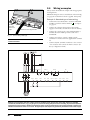
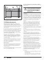
3.4
Wiring examples
Always ensure the installation complies with the appropriate
local regulations.
Minimum wiring for remote controlled start is shown in Fig.
19, page 30, in which level control is applied, menu [21A].
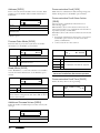
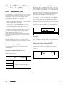
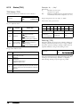
Example 1: Standard type of start wiring
Earthing
plate with
slots for tie
wraps
U
•
Connect Protective Earth (PE) to earth bar marked PE
and Motor earth the earth bar marked
see chapter
3.1 page 12.
•
Connect the softstarter between the 3-phase mains
supply (L1, L2 and L3) and the motor (T1, T2 and T3).
•
Connect the control supply voltage (100-240 VAC) to
terminals N and L and the protective earth wire to
terminal PE.
•
Connect start and stop control to DigIn 1 and 2
(terminals 11 and 12) with 24 V supplied from terminal
18.
•
Connect relay R1 (terminals 21 and 22) to the contactor
– the softstarter then controls the mains contactor (for
factory configuration of R1).
I
Shielded control signal cable
Fig. 11 Control cable feedthrough.
NOTE: Shielded control cable must be used for option
board connections.
.
Relay 1
DigIn 1
Run FWD
DigIn 2
+10 V
Relay 2
AnIn
GND
PTC
Relay 3
DigIn 3
DigIn 4
+24 V
AnOut
+24 V
Stop
Fig. 12 Standard wiring example.
NOTE: If local regulations state that a mains contactor should be used, relay R1 can control this. Always use standard
commercial, slow blow fuses, e.g. gl or gG types, to protect the wiring and prevent short circuiting. To protect the thyristors
against short-circuit currents, ultrafast semiconductor fuses can be used if preferred. The normal guarantee is valid even if
ultrafast semiconductor fuses are not used. All signal inputs and outputs are galvanically insulated from the mains supply.
16
Connections
CG Drives & Automation 01-5980-01r0
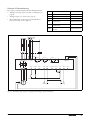
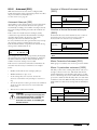
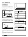
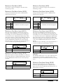
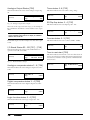
Example 2: Extended wiring
Fig. 13 gives a wiring example with the following functions:
•
•
•
Menu
Analogue start/stop via process value, see description on
page 91.
Analogue output, see section 8.5.3, page 95
Motor PTC input, see description of Thermal motor
protection in section 8.2.4, page 62.
Relay 1
Description
Setting
521
Digital input 1 (terminal 11)
Run FWD (default)
522
Digital input 2 (terminal 12)
Stop (default)
524
Digital input 4 (terminal 17)
Reset (default)
511
Analogue input function
(terminal 14)
Process Val (default)
531
Analogue output function
(terminal 19)
Current (default)
2331
PTC alarm action (terminal 69
Hard trip/Soft trip
and 70)
Relay 2
Relay 3
PTC
DigIn 1
DigIn 2
+10 V
AnIn
GND
DigIn 3
DigIn 4
+24 V
AnOut
+24 V
Reset
Run FWD
Stop
Process value
Measuring
Fig. 13 Extended wiring example, using digital and analogue inputs and outputs.
CG Drives & Automation 01-5980-01r0
Connections
17
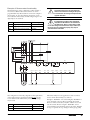
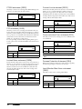
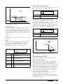
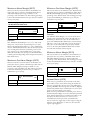
Example 3: Reverse current brake wiring
operation the first contactor (K1) will be activated (Fig. 14,
page 18). For braking R1 will open and the second contactor
(K2) will be activated via R2 to change the phase sequence.
The example in Fig. 14 shows the wiring for a reverse
current brake functionality. For further settings, see the
description for “Dynamic Vector Brake” on page 81.
Menu
The contactors have to be controlled by the relay outputs of
the softstarter. For relay settings, see menu [550] and Fig. 54,
page 99. The relay (R1) for the first mains contactor (K1) is
set to “RunSignalFWD” in menu [551], and will control the
mains contactor (K1). The second mains contactor (K2) is
controlled by another relay (R2), that is set to
“RevCurrBrake” in menu [552]. During start and full voltage
Relay 1
DigIn 1
DigIn 2
Run FWD
+10 V
521
Setting
Digital input 1 (terminal 11)
Run FWD (default)
522
Digital input 2 (terminal 12)
Stop (default)
551
Relay 1 (terminals 21 and 22) RunSignalFWD
552
Relay 2 (terminals 23 and 24) RevCurrBrake
Relay 2
AnIn
Description
GND
Relay 3
DigIn 3
PTC
DigIn 4
+24 V
AnOut
+24 V
Stop
Fig. 14 Reverse current brake wiring example.
18
Connections
CG Drives & Automation 01-5980-01r0
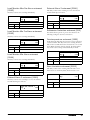
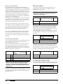
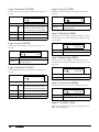
Example 4: Reverse start functionality
The digital inputs can be configured to enable starting a
motor in two different directions with the use of the
programmable relays R1 and R2. A connection example is
shown in Fig. 15. For the following description of start
forward/reverse functionality, the following settings for the
digital inputs are assumed.
Menu
Description
!
WARNING!
If configured according to the description,
relays R1 and R2 will never be activated at
the same time. There is a time delay of 100
ms for the change-over between the relays. However, if
the relays are not configured properly, they may be
activated at the same time.
Setting
521
Digital input 1 (terminal 11)
Run FWD (default)
522
Digital input 2 (terminal 12)
Stop (default)
523
Digital input 3 (terminal 16)
Run REV
CAUTION!
Very high torque/force can arise when the
motor is reversed from running at full speed
in one direction to running at full speed in the
opposite direction.
.
Relay 1
DigIn 1
Run FWD
DigIn 2
+10 V
Stop
PTC
Relay 2
AnIn
GND
DigIn 3
DigIn 4
+24 V
AnOut
+24 V
Run REV
Fig. 15 Connection for start forward/reverse.
The configuration of the relays depends on the requirements
of the application. For applications which do not use the
reverse current brake functionality, the following settings
may be used.
Menu
Description
Setting
551
Relay 1 (terminals 21 and 22)
Operation FWD
552
Relay 2 (terminals 23 and 24)
Operation REV
CG Drives & Automation 01-5980-01r0
The functionality for both applications (with or without
reverse current functionality) is as follows:
If DigIn 1 “RunFWD” is closed and DigIn 3 “RunREV” is
open, the mains contactor (K1) for running in forward
direction will be activated by relay R1, and the motor will
start in forward direction. DigIn 1 “RunFWD” can be
opened during forward running without any effect. If DigIn
2 “Stop” is opened, the stop settings in menu group [340]
Connections
19
will be performed. When the stop is finished, the mains
contactor for running forward (K1) will be deactivated by
relay R1.
If both DigIn 1 “Stop” and DigIn 3 “RunREV” are closed
while DigIn 1 “RunFWD” is open, the mains contactor for
running in reverse direction (K2) will be activated by relay
R2 and the motor will start in reverse direction. DigIn 3
“RunREV” can be opened during reverse running without
any effect. If DigIn 2 “Stop” is opened, a stop according to
the stop settings in menu group [340] will be performed.
When the stop is finished, the mains contactor for reverse
running (K2) will be deactivated by relay R2.
If both DigIn 1 “RunFWD” and DigIn 3 “RunREV” are
closed at the same time, a stop is performed according to the
stop settings in menu group [340]. In this case no start will
be allowed.
A motor can switch from forward to reverse direction as
follows: Open DigIn 1 “RunFWD” while the motor is
running in forward direction. Then close DigIn 3
“RunREV”. As a result the voltage to the motor is switched
off and the mains contactor for forward running (K1) is
deactivated by relay R1. After a time delay of 100
milliseconds, the mains contactor for reverse running (K2)
will be activated by relay R2, and a start in reverse direction
will be performed. The motor can switch from reverse to
forward running in the same way by opening DigIn 3
“RunREV” while running in reversed direction and then
closing DigIn 1 “RunFWD”.
20
Connections
CG Drives & Automation 01-5980-01r0
4.
Application guidelines
This chapter is a guide to selecting the correct softstarter
rating and softstarter functionality for different applications.
Current
To make the right choice the following tools are used:
The AC-53 norms
Start current
The AC-53 norms are defined in the EN(IEC) 60947-42:2007 standard for electronic softstarters. The purpose of
these norms is to aid in selecting a softstarter with regards to
duty cycle, starts per hour and maximum starting current.
The Applications Rating List
Time
With this list the Emotron TSA softstarter rating type can be
selected depending on the type of application uses, see Table
12, page 22.
Start
The Applications Function List
This table gives an overview of the most common
applications and their challenges. For each application
Emotron TSA softstarter settings are proposed, with
references to the menus used. See Table 13, page 24.
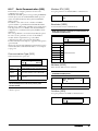
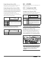
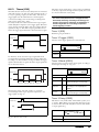
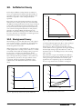
4.1
Softstarter dimensioning
according to AC-53b
The EN(IEC) 60947-4-2:2007 standard defines AC-53b as
a norm for dimensioning of softstarters for continuous
running with a bypass contactor. This is the norm for which
the Emotron TSA is designed.
Bypass
operation
Fig. 16 Duty cycle.
4.2
Applications rating
According to the AC-53b norm a softstarter can have several
current ratings. The Applications Rating List in Table 12,
page 22 shows which rating that is recommended for the
application.
The Emotron TSA model is selected depending on its model
size and on the duty cycle of the application:
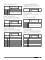
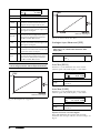
AC-53b ratings for Emotron TSA size 1:
AC-53b rating example
•
AC-53b 3.0-15:345 (normal duty with bypass)
Explanation of the rating designation (see also Fig. 16):
•
AC-53b 5.0-15:345 (heavy duty with bypass)
56 A: AC-53b 3.0 - 30 : 330
1. Rated current (FLC) of softstarter, [Ampere]
2. Classification (AC-53b for all Emotron TSA models)
3. Start current expressed as a multiple of FLC
AC-53b ratings for Emotron TSA size 2 - 6:
•
AC-53b 3.0-30:330 (normal duty with bypass)
•
AC-53b 5.0-30:330 (heavy duty with bypass)
NOTE: To select softstarter size it is important to ensure
that not only FLC (Full Load Current) is checked but also
the starting requirements.
4. Start time, [seconds]
Example:
5. Bypass time, [seconds]
In the previous example, in which the Emotron TSA 52-056
is used for a pump application, the recommended rating is
“normal duty” according to the Applications Rating List.
The example concerns Emotron TSA model 52-056, used
for a pump application. The rating designation indicates a
current rating of 56 A with a start current ratio of 3.0 x FLC
(168 A) for 30 seconds, and with a 330 seconds (5.5
minutes) interval between starts (current via bypass
contactors).
CG Drives & Automation 01-5924-01r0
Application guidelines
21
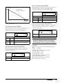
Applications Rating List
This list gives the typical rating type for the machine or
application, divided in “normal duty” and “heavy duty”
applications (both with bypass). If the machine or
application is not in this list, try to identify a similar
machine or application. If in doubt please contact your
Emotron TSA supplier.
Example:
rated differently according to the Applications Rating List.
Due to high starting current a roller mill is considered a
heavy duty application, which places greater demands on the
softstarter. The technical data (page 139) indicates that the
TSA 52-056 is downrated to 33 A FLC for heavy duty
applications. If an FLC current of about 56 A is required for
the roller mill, it would be recommended to choose TSA
model 52-100, for which the rated heavy duty current is 60
A.
If the Emotron TSA 52-056 from the previous example is
used in e.g. a roller mill application instead, it would be
Table 12 Applications Rating List
Applications rating for Emotron TSA softstarter
Industry
General & Water
Normal duty cycle AC53b-3.0
Centrifugal pump
Submersible pump
Compressor, screw
Compressor, reciprocating
Fan
Blower
Dust collector
Grinder
Metals & Mining
Food processing
Bottle washer
Slicer
Pulp & Paper
Lumber & Wood
Petrochemical
Transport & Machine
22
Application guidelines
Heavy duty cycle AC53b-5.0
Conveyor
Mixer
Agitator
Belt conveyor
Hammer mill
Rock crusher
Roller conveyor
Roller mill
Tumbler
Wire draw machine
Centrifuge
Dryer
Mill
Palletiser
Repulper
Shredder
Trolley
Bandsaw
Chipper
Circular saw
Debarker
Planer
Sander
Ball mill
Centrifuge
Extruder
Screw conveyor
Ball mill
Grinder
Material conveyor
Palletiser
Press
Roller mill
Rotary table
Trolley
Escalator
CG Drives & Automation 01-5924-01r0
4.3
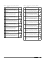
The Application Functions List
This list gives an overview of many different applications
with their challenges and a possible solution within the
functions of the Emotron TSA.
Example: Hammer mill
•
Linear torque control (menu [331], selection ”Lin Torq
Ctr”) will give the best results.
Description and use of the table:
•
Torque boost to overcome high breakaway torque (menu
[337], submenus [3371]and [3372]).
“Application”
•
Overload alarm function for jamming protection (menu
[410] “Load Monitor”, with submenus for maximum
alarm)
This column gives the various applications. If the machine
or application is not found in this list, try to identify a
similar machine or application. If in doubt please contact
your supplier.
“Challenge”
Stop function reverse current brake (set “Stop Method”
[341] to “Brake”, and menu [344] to “Rev Curr Brk”). It is
possible to set a “Reversed Current Braking Delay” in menu
[346].
This column describes possible challenges that are familiar
for this kind of application.
“Emotron TSA Solution”
This column gives the possible solution for the challenge
using one of the functions of the Emotron TSA.
“Menu/Chapter”
This column guides you to the menu, menu group, or
manual section where you find a description of the settings
for the function.
For instance "331=Sqr Torq Ctr", means: set parameter
[331] to “Sqr Torq Ctr.”
CG Drives & Automation 01-5924-01r0
Application guidelines
23
.
Table 13 Application Functions List
Application
PUMP
Challenge
BLOWER
Square torque control for square loads
Water hammer
High current and peaks during starts
Pump is going in wrong direction
Dry running
High load due to dirt in pump
Mechanical shock for compressor, motor and
transmissions
Square torque control
Square torque control
Phase reversal alarm
Use load monitor minimum alarm
Use load monitor maximum alarm
331=Sqr Torq Ctr
341=Sqr Torq Ctr
340
330
444
410
410
Linear torque control
330
Screw compressor going in wrong direction
Damaged compressor if liquid ammonia
enters the compressor screw.
Energy consumption due to compressor
running unloaded
FAN
PLANER
24
Linear torque control and current limit 331=Lin Torq Ctr
at start.
335
Phase reversal alarm
444
Use load monitor maximum alarm
410
Use load monitor minimum alarm
410
Mechanical shock for blower, motor and
transmissions. High start current requires
large cables and fuses.
Torque control ensures smooth starts
that minimise mechanical stress.
Start current is minimised by torquecontrolled start.
331=Lin Torq Ctr
Mechanical shocks for transmissions and
transported goods.
Linear torque control
330
Slow speed and accurate position
control.
Use load monitor maximum alarm
350
600
410
Use load monitor minimum alarm
410
Loading or unloading conveyors
CONVEYOR
Menu/Chapter
Non-linear ramps
Small fuses and low current available.
COMPRESSOR
Emotron TSA Solution
Conveyor jammed
Conveyor belt or chain is off but the motor is
still running
Starting after screw conveyor has stopped
due to overload.
Conveyor blocked when starting
High starting current in end of ramps
Slivering belts.
JOG in reverse direction and then
starting in forward.
Locked rotor function
Square torque control for square load
characteristics
Catching the motor and stopping
Fan is going in wrong direction when starting. smoothly to zero speed and then
starting in right direction.
Belt or coupling broken
Use load monitor minimum alarm
Blocked filter or closed damper.
High inertia load with high demands on
Linear torque control gives linear
torque and current control.
acceleration and low starting current.
7.1, p. 39
422
330
331=Sqr Torq Ctr
410
330
341=Brake
Dynamic vector brake without contactor
344=Dyn Vect Brk
Need to stop quickly both for emergency and for medium loads.
347
production efficiency reasons.
Reverse current brake with external
341=Brake
contactor for heavy loads.
344=Rev Curr Brk
Conveyor speed set from planer shaft
High speed lines
530
power analogue output.
Worn out tool
Use load monitor maximum alarm
410
Broken coupling
Use load monitor minimum alarm
410
Application guidelines
CG Drives & Automation 01-5924-01r0
Table 13 Application Functions List
Application
Challenge
High inertia
Heavy load when starting with material
Low power if a diesel powered generator is
ROCK CRUSHER used.
Wrong material in crusher
BANDSAW
CENTRIFUGE
MIXER
HAMMER MILL
Emotron TSA Solution
Menu/Chapter
Linear torque control gives linear
acceleration and low starting current.
Torque boost
337
Current limit at start
335
330
410
341=Brake
Vibrations during stop
Dynamic vector brake without contactor 344=Dyn Vect Brk
347
High inertia load with high demands on
Linear torque ramp gives linear
330
torque and current control.
acceleration and low starting current.
341=Brake
Dynamic vector brake without contactor
344=Dyn Vect Brk
for medium loads.
347
Need to stop quickly.
Reverse current brake with external
341=Brake
contactor for heavy loads.
344=RevCurr Brk
Conveyor speed set from bandsaw
High speed lines
530
shaft power analogue output.
Worn out saw blade
Use load monitor maximum alarm
410
Broken coupling, saw blade or belt
Use load monitor minimum alarm
410
Linear torque control gives linear
High inertia load
330
acceleration and low starting current.
Too high load or unbalanced centrifuge
Use load monitor maximum alarm
410
341=Brake
Dynamic vector brake without contactor
344=Dyn Vect Brk
for medium loads.
347
Controlled stop
Reverse current brake with external
341=Brake
contactor for heavy loads.
344=Rev Curr Brk
Braking down to slow speed and then 340, 350
Need to open centrifuge in a certain position.
positioning control.
600, 650
Linear torque control gives linear
Different materials
330
acceleration and low starting current
Need to control material viscosity
Shaft power analogue output
530
Broken or damaged blades
Use load monitor maximum alarm
410
Use load monitor minimum alarm
410
Linear torque control gives linear
331=Lin Torq Ctr
acceleration and low starting current.
Heavy load with high breakaway torque
Torque boost in beginning of ramp.
337
Jamming
Use load monitor maximum alarm
410
Reverse current brake with reversing 341=Brake
Fast stop
contactor for heavy loads.
344=Rev Curr Brk
Motor blocked
Locked rotor function
422
CG Drives & Automation 01-5924-01r0
Use load monitor maximum alarm
Application guidelines
25
4.4
Special conditions
4.4.1 Small motor or low load
The minimum load current for the Emotron TSA softstarter
is 10% of the rated current for the softstarter. An exception
is the TSA52-016 for which the minimum load current is
2 A.
Example: TSA52-056 with rated current of 56 A has a
minimum current of 5.6 A.
Please note that this is “minimum load current” and not
minimum rated motor current.
4.4.2 Ambient temperature below
0°C
For ambient temperatures below 0 °C an electric heater or
similar must be installed in the cabinet. The softstarter can
be mounted remotely from the motor since the distance
between the motor and the softstarter is not critical.
4.4.3 Pump control with softstarter
and AC drive together
It is possible, e.g. in a pump station with two or more
pumps, to use one Emotron FDU AC drive on one pump
and softstarters on each of the other pumps. The flow of the
pumps is then controlled by the pump control function in
the Emotron FDU.
4.4.4 Starting with counterclockwise (reverse) rotating
loads
It is possible to start a motor clockwise (forward direction),
even if the load and motor are rotating counterclockwise
(reverse direction), e.g. fans. Depending on the speed and
the load “in the wrong direction”. Pleas note that the current
can be quite high.
4.4.5 Running motors connected in
parallel
When starting and running motors connected in parallel,
the total amount of the motor current must be equal or
lower than the rating of the connected softstarter. Please
note that it is not possible to use the internal thermal motor
protection or use other individual settings for each motor.
For instance, the start ramp can only be set for an average
starting ramp for all the connected motors. This means that
the start time may differ from motor to motor. Similarly, the
load monitor alarm levels/margins are applied for the
average shaft power value of the connected motors. In order
to work around this kind of problem, it could be necessary
to deactivate a number of functions and alarms.
motors. Voltage control with or without current limit is
recommended instead. The use of the braking functionality
is not recommended for motors connected in parallel.
4.4.6 Running motors linked
together
When starting and running motors mechanically linked
together but with one softstarter connected to each motor,
there are two kinds of operations available. The first is to
start the motors at the same time using voltage control with
or without current limit. The second is to start one motor
first with torque or voltage control and after the motor has
reached full speed, the voltage to the other motors is ramped
up using voltage control.
4.4.7 Heat dissipation in cabinets
For guidelines regarding calculation of heat dissipation in
cabinets, please contact your cabinet supplier. The required
data is found in “Technical Data”, Chapter 13. page 139.
4.4.8 Insulation test on motor
When testing the motor with high voltage e.g. insulation
test, the softstarter must be disconnected from the motor.
This is due to the fact that the softstarter will be seriously
damaged by the high test voltage.
4.4.9 Operation above 1,000 m
All ratings are stated for operation at maximum 1,000 m
over sea level.
If the softstarter is operated at 3,000 m for example, it must
be derated, and it is likely that a higher rated model than
normal is required to fulfil the task. See further information
in section 13.3.2, page 143.
4.4.10 Aggressive environment
conditions
As standard the Emotron TSA is equipped with coated
boards in order to reduce the risk for corrosion. For
specification, see section 13.3, page 142.
4.4.11 IT earthing system
Distribution systems may be equipped with an IT isolated
earthing system, which allows for one earth fault to occur
without interruption of operation. For use in these systems,
the Emotron TSA should be ordered with IT-net option.
If you have a softstarter without IT net option, the
softstarter can be rebuilt. Contact your local CG Drives &
Automation service partner.
For motors connected in parallel, torque control is not
recommended because of the risk of oscillation between the
26
Application guidelines
CG Drives & Automation 01-5924-01r0
4.4.12 Earth fault relay
It is possible to use an earth fault relay to protect motor and
cables (not for human safety). To avoid undesired tripping
due to filter capacitor charging currents, choose a short-time
delayed residual current device rated for 30 mA leakage
current.
4.4.13 Other control voltage
The power board must be connected to 100-240 VAC single
phase control supply. If this is not available a transformer
must be used. This transformer should be connected as in
Fig. 17.
The transformer should be capable of supplying a power of
50 VA or more. This item is not included in the range of
CG options.
Transformer
Emotron TSA
Fig. 17 Example of wiring when using transformer for 380 - 500 VAC
CG Drives & Automation 01-5924-01r0
Application guidelines
27
28
Application guidelines
CG Drives & Automation 01-5924-01r0
5.
Getting started
This chapter is a step by step guide that will show you the
quickest way to get the motor shaft turning. We will show
you two examples: with remote control and control panel
operation.
WARNING!
Mounting, wiring and setting the device into
operation must be carried out by properly
trained and qualified personnel.
5.1
Check list
•
Check that the motor and supply voltage corresponds to
the values on the rating plate of the softstarter.
•
Mount the softstarter (Chapter 2. page 9 ).
•
Connect the 3-phase mains supply cables to the connections on top of the softstarter (section 3.1, page 12).
•
Connect the motor cables to the connections in the
bottom of the softstarter (section 3.1, page 12).
•
Connect control supply voltage (section 3.1, page 12).
•
Ensure that the installation complies with the
appropriate local regulations.
Remote (I/O) operation:
•
Connect the I/O control cables (section 3.3, page 15).
•
Switch on the 3-phase mains supply voltage and control
supply voltage.
•
Select language (menu [211], section 8.2.1, page 57).
•
Set the motor data (menu [220] - [227], section 8.2.3,
page 60).
•
Set real time clock (menu [740], section 8.7.4, page 119)
•
Perform a test run with external I/O start command.
Control panel operation:
•
Switch on the 3-phase mains supply voltage and control
supply voltage.
•
Select language (menu [211], section 8.2.1, page 57).
•
Set the motor data (menu [220] - [227], section 8.2.3,
page 60).
•
Set real time clock (menu [740], section 8.7.4, page 119)
•
Select keyboard control (menu [2151], section 7.1.1,
page 39).
•
Perform a test run from the control panel.
CG Drives & Automation 01-5980-01r0
5.2
Mains and motor
connection
Connect the softstarter between the 3-phase mains supply
and the motor. For the respective connections, see the table
below).
Dimension the mains and motor cables according to local
regulations. The cables must be able to carry the softstarter
load current (see “Technical data” on page 139).
Table 14
Mains and motor connection
L1, L2, L3
PE
Mains supply, 3-phase
Protective earth
T1, T2, T3
Motor output, 3-phase
Motor earth
WARNING!
In order to work safely the mains earth must
be connected to PE and the motor earth to
.
5.2.1 Connect the mains cables
The connection of the mains cables is shown in section 3.1,
page 12. As standard the Emotron TSA softstarter has a
built-in RFI mains filter that complies with category C1
which is suited for environment B.
5.2.2 Connect the motor cables
The connection of the motor cables is shown in section 3.1,
page 12.
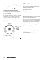
5.2.3 Connect the control supply
voltage
The control supply voltage is connected to the terminals
marked N and L on the power board (Fig. 19).
Getting started
29
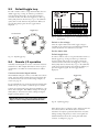
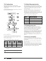
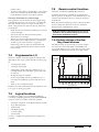
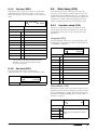
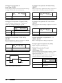
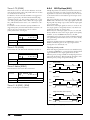
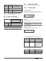
5.3
Default toggle loop
In order to make it easier to setup the initial data, there is a
default toggle loop, see Fig. 18. This loop contains the
necessary menus that need to be set before starting the
softstarter the first time. Press the Toggle key to enter e.g.
menu [740], then use the next keys to go to the submenus
([741] and so forth) and enter the parameters. When you
press the Toggle key again, the next toggle menu is
displayed.
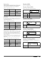
Start /Stop
100-240V
PE
Control board
Power board
Toggle loop
To submenus
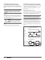
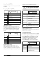
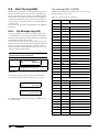
Fig. 19 Minimum wiring for remote controlled start using
level control.
Switch on the voltage
Once the 3-phase mains and control supply voltage is
switched on, the softstarter is started and the internal fan
(only in model sizes 2-6) will run for 5 seconds.
Set the basic data
Default toggle loop
Fig. 18 Default toggle loop
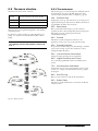
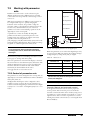
5.4
Remote I/O operation
Generally, external signals are used to control the softstarter
and the motor. This example demonstrates the set-up for a
standard motor for which an external start button will be
used.
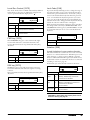
In order to make it easier to setup the initial data, there is a
default toggle loop, see Fig. 18. This loop contains the
necessary menus that need to be set before starting the
softstarter the first time. Press the Toggle key to enter e.g.
menu [740], then use the next keys to go to the submenus
([741] and so forth) and enter the parameters. When you
press the Toggle key again, the next toggle menu is
displayed.
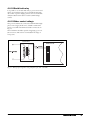
Connect the control signal cables
The minimum wiring for a remote controlled start is shown
in Fig. 19 below. In this example the motor/softstarter will
run with forward rotation. For other wiring examples, see
section 3.4, page 16.
Toggle loop
To submenus
It is recommended to use screened control signal cables with
flexible wire up to 1.5 mm2, or solid wire up to 2.5 mm2.
Connect an external start button between terminal 18 (+24
VDC) and 11 (DigIn 1, Run FWD). Change the setting in
menu [21A] to “Level” (level control). Change setting for
DigIn 2 in menu [522] to “Off ”.
NOTE: Default setting is edge control (menu [21A] set to
“Edge”) in order to comply with the Machine directive.
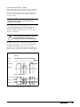
Fig. 20 Default toggle loop
Enter the basic data, i.e. language, time, and motor data for
the connected motor. The motor data is used in the
calculation of complete operational data in the softstarter.
Change settings using the keys on the control panel. For
further information about the control panel and menu
structure, see Chapter 6. page 33.
30
Getting started
CG Drives & Automation 01-5980-01r0
Menu [100], “Preferred View” is displayed at start.
5.5
1. Press
A manual test run can be executed via the control panel.
This example demonstrates the set-up to carry out for a
standard motor.
NQE1
TGO
to display menu [211] “Language”.
Select Language using the
Confirm with
2. Press
NQE1
TGO
and
keys.
.
to display menu [221] “Motor Volts” and set
nominal motor voltage. Change the value using the
and
keys. Confirm with
.
Control panel operation
Switch on the voltage
Once the 3-phase mains and control supply voltage is
switched on, the softstarter is started and the internal fan
(only in sizes 2-6) will run for 5 seconds.
Perform in a similar way the following settings:
Set the basic data
3. Set motor frequency [222].
Enter the basic data, i.e. language, time, and motor data for
the connected motor. Perform this the same way as for
“Remote I/O operation” on page 30.
Follow the steps 1 - 10.
4. Set motor power [223].
5. Set motor current [224].
6. Set motor speed [225].
Then press
View”.
7. Set power factor (cos φ) [227].
8. Press
9. Press
NQE1
TGO
to display menu [740]”Clock setting”.
Select manual control
to display menu [741]” Time”. Change the
1. Press
to display menu [200], “Main Setup”.
2. Press
to display menu [210], “Operation”.
3. Press
until you get to menu [215] “Action Control”,
time using the
and
keys. To activate setting of
hh.mm.ss respectively, use the
Confirm with
10. Press
until you return to menu [100],”Preferred
or
keys.
.
to display menu [742]” Date” and set date.
Confirm with
.
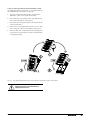
11. Switch off power supply.
12. Connect digital and analogue inputs/outputs as in
Fig. 19.
13. Switch on power supply.
NOTE: For selection of other start method than the
default “linear torque control”, see section 7.1.2, page
35
Test run with external start command
Now the installation is finished, press the external start
button (contact closed) to start the motor.
NOTE: When the internal bypass contactor is activated,
three distinct clicks are heard.
then press
to go to submenu [2151] “Run/Stop
Control”.
4. Select “Int keyb” using the key
Press
.
to confirm.
Test run from control panel
Press the
forward.
key on the control panel to run the motor
NOTE: When the internal bypass contactor is activated,
three distinct clicks are heard.
To stop the motor, press the
key on the control panel.
NOTE: For selection of other stop method than the
default “Coast”, see section 7.1.2, page 35 and menu
[341].
To stop the motor, disconnect the start command (contact
open).
NOTE: For selection of other stop method than the
default “Coast”, see section 7.1.2, page 35 and menu
[341].
CG Drives & Automation 01-5980-01r0
Getting started
31
32
Getting started
CG Drives & Automation 01-5980-01r0
6.
Operation via the control panel
The control panel displays the status of the softstarter and is
used to set all the parameters. It is also possible to control
the motor directly from the control panel.
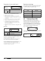
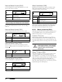
6.1 Display
The display is back lit and consists of 2 rows, each with
space for 16 characters. The display is divided into six areas.
The different areas in the display are described below:
221 T
Stp A M1
Motor Volt
400V
LCD display
LEDs
Fig. 22 LC display
Control keys
Area A:
Shows the actual menu number (3 or 4 digits).
Area B:
Shows if the menu is in the Toggle loop
(page 35), indicated with , and/or if the softstarter is set for “Local” operation (page 36),
indicated with .
Area C:
Shows the abbreviated name of the active menu,
e.g. parameter or description of the contents.
Area D:
Shows the status of the softstarter (3 characters).
The following status indications are possible:
Toggle key
Function keys
Acc: Motor starting
Fig. 21 Control panel
Dec: Motor stopping
I2t: Active I2t motor protection
Run: Motor runs at full speed
Jog: Motor runs at jog speed
Trp: Tripped
Stp: Motor is stopped
CG Drives & Automation, 01-5980-01r0
Area E:
Shows active parameter set:
, , , or
;
and if it is a motor parameter: M1, M2, M3, or
M4.
Shows a flashing cursor when a change is being
done to the actual menu parameter.
Also shows “S” to indicate soft trip, and “A” if
max number of autoreset attempts is exceeded.
Area F:
Shows the setting or selection in the active
menu (empty at 1st level and 2nd level menus).
Shows warnings and alarm messages.
Operation via the control panel
33
6.2 LED indicators
The three light emitting diodes below the display indicate
the operation status of the softstarter and motor/machine
(see Fig. 23). Depending on the operating mode the TRIP
and RUN indicators will also flash to alert the user about a
coming event or action. A description of the different LED
signals is given in Table 15 below.
RUN
(green)
TRIP
(red)
POWER
(green)
Fig. 23 LED indicators
Table 15
LED indication
Status:
LED symbol:
POWER
(green)
ON
NORMAL FLASHING (2 Hz)*
SLOW FLASHING (1 Hz)*
----------------
---------------
Mains supply
power on
TRIP
(red)
RUN (green)
Softstarter tripped
Warning
Running at full speed
Start and stop ramp
OFF
Power off
Awaiting autoreset of trip
(simultaneously flashing
RUN and TRIP LEDs)
No trip
Softstarter not active
*) Frequency: 1 Hz=1 flash per second; 2 Hz=2 flashes per second
6.3 Control keys
6.4 Function keys
The control keys are used to give the START, STOP or
RESET commands directly. As default the START and
STOP keys are disabled and the commands are set remotely
(from digital input).
The function keys operate the menus and are also used for
programming and read-outs of all the menu settings.
To enable START commands (reverse and forward run)
from the control keys, go to the description in section 7.1.1,
page 39, menu [2151].
Function key commands.
ENTER
Step to lower menu level.
Confirm a changed setting.
ESCAPE
Step to higher menu level.
Ignore a changed setting (without confirming).
PREVIOUS
Step to previous menu within
the same level.
Move cursor one position to the
left.
START REVERSE RUN
Start with reversed
(left) rotation.
(Requires reversing
contactor).
NEXT
Step to next menu within the
same level.
Move cursor one position to the
right.
STOP/RESET
Stop motor.
Reset softstarter (after
a trip).
- (MINUS)
or
JOG REV
Decrease a value.
Change a selection.
Or:
Start reverse jog function.
START FORWARD RUN
Start with forward
(right) rotation.
+ (PLUS)
or
JOG FWD
Increase a value.
Change a selection.
Or:
Start forward jog function.
The RESET key is activated by default. It will remain active
as long as one of the keyboard alternatives is selected in
menu [216]).
If the “Enable” function is programmed on one of the digital
inputs, this input must be active to allow START/STOP
commands from the control panel.
Table 16
Table 17
Control key commands.
NOTE: It is not possible to simultaneously activate the
Run/Stop commands from the keyboard and remotely
from the terminal strip. Exception is the Jog-function
which can give a start command, see “Jog functions” on
page 40.
34
Operation via the control panel
CG Drives & Automation, 01-5980-01r0
6.4.1 +/- key function
6.4.2 Jog key function
To manually change a value or a selection, or to enter a new
value, the “+” and “-” keys are used. For this function to be
active, the keyboard must be unlocked (as it is by default),
menu [218].
The “+” and “-” keys can be programmed for jogging,
enabling a manual jog start to be done from the control
panel by pressing and holding the key.
Changing parameter selection
To change selection in a menu, press the “+” or “-” keys to
scroll between the available alternatives. The cursor to the
left (area E) is flashing while doing so. To confirm a
selection, press ENTER, and the cursor will stop flashing.
To activate the jog key function, see instructions in “Jog
functions” on page 40.
To deactivate the jog key function, unlock the keyboard in
menu [218].
6.5 Toggle and Loc/Rem Key
This key has two functions: toggling between
selected menus, and switching between local
and remote operation control.
Editing parameter values
Most of the parameters can be changed during operation
without stopping the softstarter.
The parameters that can not be changed during operation
are in this manual marked with a lock symbol: .
NOTE: If you try to change a function during operation
that only can be changed when the motor is stopped, the
message “Stop First” is displayed.
•
•
•
To change a parameter value, press the “+” or “-” keys.
The cursor to the left is flashing while the value is
increased or decreased. If you keep the “+” or “-” keys
pressed, the value will increase or decrease continuously.
For bigger changes you can also directly select a digit
with the cursor using the PREV and NEXT keys, and
change this with the “+” or “-” keys.
Press the Toggle key to change the sign of the entered
value (only valid for certain parameters). The sign of the
value will also change when zero is passed.
•
Press ENTER to confirm the value. The cursor to the
left will stop flashing.
•
Press ESC to leave the edit mode.
Entering lock code
The lock code in menu [218] is inserted from the right to
the left, the position indicated with a cursor. The digit is set
by scrolling with the +/- keys, and the cursor is moved with
the PREV key to the left, in order to enter the next symbol.
Then the NEXT key can be used to go to the right and
change something if needed. When finished this is
confirmed with ENTER.
NOTE: When the control panel is locked, the only menu
in which it still is possible to use the +/- keys, is [218]
“Lock Code”.
This method is also used for new entries in e.g. User Unit, or
Unit Name. Digits or characters are added from right to left
in the same way as described above.
CG Drives & Automation, 01-5980-01r0
If the key is programmed for “Toggle”
(default in menu [2171]), it will only have
the toggle function.
If the key is programmed for “Loc/Rem” in menu [2171], it
can only be used to switch between local and remote control
of the softstarter.
If the key is programmed for “Combined” in menu [2171],
the key can be used for both functions in the following
manner:
•
Press one second to use the toggle function.
•
Press and hold the toggle key for more than five seconds
to enable the choice between Local or Remote function,
see section “Loc/Rem function” on page 36.
When editing parameter values, the toggle key can be used
to change the sign of the value.
6.5.1 Toggle function
Using the toggle function makes it possible to easily step
through selected menus in a loop. The toggle loop can
contain a maximum of ten menus. As default the toggle loop
contains the menus needed for Getting Started. You can also
use the toggle loop to create a quick-menu for the
parameters that are most important to your specific
application.
NOTE: Do not keep the Toggle key pressed for more than
five seconds without pressing either the “+”, “-”, or ESC
key, as this may activate the Loc/Rem function of this
key instead. See menu [2171].
Add a menu to the toggle loop
1. Go to the menu you want to add to the loop.
2. Press the Toggle key and keep it pressed while also pressing the “+” key.
3. Check that a “ ” is shown to the right of the menu
number (area B).
Operation via the control panel
35
Delete a menu from the toggle loop
6.5.2 Loc/Rem function
1. Go to the menu you want to delete using the toggle key.
With the Loc/Rem function you can change between local
and remote control of the softstarter from the control panel.
The Loc/Rem function of the key is disabled as default.
Enable the function in menu [2171].
2. Press the Toggle key and keep it pressed while pressing
the “-” key.
3. Check that there is no longer a “
of the menu number.
” symbol to the right
Delete all menus from the toggle loop
1. Press the Toggle key and keep it pressed while pressing
the ESC key.
2. Confirm with ENTER.
The function Loc/Rem can also be changed via DigIn, see
menu “Digital inputs [520]”.
Change control mode
1. Press the Loc/Rem key for five seconds, until “Local?” or
“Remote?” is displayed,
2. then confirm with ENTER,
Default toggle loop
Fig. 24 shows the default toggle loop. This loop contains the
necessary menus that need to be set before starting the
softstarter the first time. Press the Toggle key to enter e.g.
menu [211], then use the NEXT key to go to the submenus
([212] and so forth) and enter the parameters. When you
press the Toggle key again, the next toggle menu is
displayed.
Toggle loop
To submenus
212
3. or cancel with ESC.
When using the LOC/REM key it is important to define
what “LOCAL” and “REMOTE” will mean:
Local mode
The “LOCAL” function is set up in the menu “Local Run
Control” [2173], for which the factory default selection is
“Keyboard”. The actual status of the softstarter will not
change, e.g. Run/Stop conditions will remain exactly the
same. When the softstarter is set to Local operation, the
display will show “ “ in area B of the display (alternating
with “ ” if it is also a toggle loop menu).
Remote mode
The “REMOTE” function is defined in menu [2151]
“Run/Stop Control”, where default is “Remote”.
To monitor the actual Local or Remote status of the
softstarter control, a “Loc/Rem” signal is available for the
Relays [550]. When the softstarter is set to “LOCAL”, the
signal on the relay will be active/high. In “REMOTE” the
signal will be inactive/low.
Fig. 24 Default toggle loop
Indication of menus in toggle loop
Menus included in the toggle loop are indicated with a
in area B of the display.
36
Operation via the control panel
CG Drives & Automation, 01-5980-01r0
6.6 The menu structure
6.6.1 The main menu
The menu structure consists of 4 levels:
This section gives you a short description of the functions in
the main menu. For a more detailed description of the
contents under each main menu, see chapter 8. page 55.
Main Menu
1st level
The first character in the menu number.
2nd level
The second character in the menu number.
3rd level
The third character in the menu number.
4th level
The fourth character in the menu number.
This structure is consequently independent of the number
of menus per level.
For instance, a menu can have two selectable menus (Jog
[350]), or it can have 12 selectable menus (Motor Data
[220]).
NOTE: If there are more than 9 menus within one level,
the numbering continues with alphabetic characters (A,
B, C, ...).
100
Preferred View
Displayed at power-up, this menu shows two actual process
signals (electrical power and current as default). The menu is
programmable for many other read-outs.
200
Main Setup
Here you find the main settings to get the softstarter
operable, the motor data settings being the most important.
The menu group also contains protection and
communication settings.
300
Process
This menu contains settings more relevant to the
application, such as start, stop, and jog mode settings.
400
Process Protection
To protect the machine and process from damage, a number
of protection settings, such as the load monitor, can be
configured under this menu.
500
I/Os and Virtual Connections
Settings for inputs and outputs are entered here.
600
Main Menu
Logical Functions and Timers
A set of freely programmable blocks are available in this
section.
700
2nd level
View Operation and Status
In this menu you can view operational data (power, torque,
current, etc.), and get status information about e.g. inputs
and outputs.
800
View Trip Log
Here you can see the last 9 trips in the trip memory.
900
3rd level
System Data
This menu contains information on softstarter model and
software version.
4th level
Fig. 25 Menu structure
CG Drives & Automation, 01-5980-01r0
Operation via the control panel
37
38
Operation via the control panel
CG Drives & Automation, 01-5980-01r0
7.
Main features
This chapter contains descriptions of the main features of
the Emotron TSA softstarter.
For configuration of programmable I/O, see the description
for the respective input/output. For a list of the different
possibilities, see section 7.4, page 51.
7.1
Local and remote control mode
Setting Start, Stop and
Run functions
7.1.1 Start and stop control
The start and stop control signals can be given from the
control panel using the control keys, via remote control (i.e.
programmable I/O), or via serial communication. The start
commands from the respective control sources depend on
which motor rotation direction that has been selected for the
motor (see Fig. 26). Follow the procedure in Fig. 27 for
setting of the start and stop signals.
An additional possibility for start and stop control is given
with the LOC/REM function of the toggle key (setting
“LOC/REM” in “Function Key” menu [2171]). It is up to
the user to define the “REMOTE” and “LOCAL” functions
in the menus for “Run/Stop Control” [2151] and “Local
Run Control” [2173]. In that respect the LOC/REM key
becomes a tool not just to alternate between the control
panel and I/O control, but actually to quickly change
between any two start and stop control locations. See
description in section 6.5.2, page 36.
7.1.2 Start and stop methods
The methods for starting and stopping the motor can be
configured in the menus [330] “Start Setting” and [340]
“Stop Setting”. See descriptions in section 8.3.3, page 78.
FWD (right)
REV (left)
Fig. 26 Rotation direction.
It is also possible to apply a “Start Limitation” [235] as part
of the actions used for protecting the softstarter. The
functions for doing this are mainly related to time settings,
e.g. limiting the numbers of starts per hour or securing a
minimum time delay between starts. For guidelines
regarding specific applications, refer to “The Application
Functions List” on page 23.
If the load monitor function [410] is activated (page 46), it
could be necessary to apply a load monitor start delay time
[417] in order to avoid faulty alarms during start-up due to
the high start current.
Spinbrake
Spinbrake can be selected as a digital input [520], see section
8.5.2, page 94. Braking is then initiated from an inactive or
active state (when running), by activating input. This means
the softstarter can catch a freewheeling motor and brake it
down to standstill.
Fig. 27 Run/Stop decision tree
CG Drives & Automation, 01-5980-01r0
Main features
39
7.1.3 Jog functions
7.1.4 Start/Stop signal priority
The jog (slow speed) function can be activated
independently from a start or stop, via the control panel
using the jog keys, via remote I/O control, or via serial
communication.
A jog command has lower priority than a normal start
command, meaning that if the softstarter is already running,
the jog command is ignored. If the softstarter is in jog mode,
a normal start command will override this and start the
motor to full speed.
To select the method to activate the jog function, follow the
procedure described in Fig. 28.
An “Enable” command (setting via Digin [520]) has the
highest priority and overrides both a normal start/stop
command and a jog command. If “Enable” is inactive it will
not be possible to execute a normal start or a jog start. The
total priority order is listed in Table 19 below.
Table 19
Signal priority for digital inputs
Priority
Digital Input selection
1
Enable
2
Spinbrake
3
Stop
4
Run FWD and Run REV
5
Jog FWD and Jog REV
7.1.5 Setting motor data
For optimal performance the Emotron TSA softstarter
should be configured according to the motor’s rating plate.
The menus for this are found in section 8.2.3, page 60;
menu group [220]. The motor data is handled as a
parameter set (one of four: M1- M4). Motor M1 is selected
as default and the motor data entered will be valid for motor
M1. If different motors are used, the motor data must be
saved under different motor data sets, selected in menu
[212]. See also “Handling motor data in parameter sets” on
page 42.
Fig. 28 Jog decision tree
It is necessary that the rotation direction settings for all
parameters involved in the jog function correlate to each
other. See Table 18 below.
Table 18
Menu
Jog settings depending on rotation direction
Forward
Jog
Reverse
Jog
Forward and
reverse jog
219
FWD
REV
FWD+REV
351
10% 1)
Off
10% 1)
352
Off
10% (1)
10% 1)
7.1.6 Process information
To set up the softstarter for a process value, menu group
[320] is used, under which a process signal and its limits can
be configured.
This can be used to create start and stop commands from
process value levels.
All the actual operational data can be viewed in the menu
group [700] Operation Status. The softstarter is by default
set to present the operational data using SI units. If needed,
this could be changed to US units in menu [21C].
1) Default value that can be changed in the respective menu.
NOTE: To jog with the control panel jog keys, press and
hold.
40
Main features
CG Drives & Automation, 01-5980-01r0
7.2
Working with parameter
sets
Parameter Set A
Parameter sets can be used to set the softstarter up for
different applications such as different motors used and
connected, start and stop methods, alarm settings, control
sources, etc.
C
Jog Control
Motor Protection
Load Monitor
A parameter set consists of virtually all changeable
parameters in the menu system. Exceptions are some
parameters that can only have one and the same value,
regardless of the selected parameter set:
[211] Language, [217] Key Functionality, [218] Lock Code,
and [260] Serial Communication. These parameter settings
are global, i.e. valid throughout the menu system.
The menus for parameter set handling are found in section
8.2.5, page 66, starting with menu [240].
The active parameter set is shown in the display to the lower
left, and can also be viewed in menu [721] TSA Status. The
detailed configuration for each set can be recorded in the
menu list that can be found in the end of this manual
alternatively be downloaded from the web at
www.cgglobal.com or www.emotron.com.
D
Braking Method
With the four parameter sets different control options can
be configured with respect to quickly changing the
behaviour of the softstarter. It is possible to adapt the
softstarter online to altered behaviour. This is based on the
fact that at any desired moment any one of the four
parameter sets can be activated during operation; via the
digital inputs or the control panel.
NOTE: Actual timer values are common for all sets. When
a set is changed the timer functionality will change
according to the new set, but the timer value will stay
unchanged.
B
Run/Stop
+24 V
DI3 Set Ctrl1
DI4 Set Ctrl2
{
Fig. 29 Selecting the parameter sets via digital input
When the parameter sets are selected via digital inputs, they
are activated as in Table 20. Activate the parameter changes
via digital input by setting menu [241] to “DigIn”.
Table 20
Parameter set
Parameter set
Set Ctrl 1
Set Ctrl 2
A
0
0
B
1
0
C
0
1
D
1
1
7.2.1 Control of parameter sets
The parameter sets can be changed via the control panel, via
digital inputs or via serial communication. This is decided in
menu [241] Select Set.
All digital and virtual inputs can be configured to select
parameter sets. Fig. 29 shows the way the parameter sets
could be activated via digital input, where for instance DigIn
3 [523] is set to “Set Ctrl 1” and DigIn 4 [524] is set to “Set
Ctrl 2”.
CG Drives & Automation, 01-5980-01r0
NOTE: The selection via the digital inputs is immediately
activated. The new parameter settings will be activated
on-line, also during Run.
NOTE: The default parameter set is parameter set A.
Example: Manual and automatic control
In an application manual control is used to prepare for
service position. After service the process is switched to
automaic control mode. This can be solved by using one set
of parameters to activate manual control mode (i.e. control
signals via I/O), and a second set of parameters to activate
running in automatic control mode (i.e. control signals from
PLC via fieldbus) .
Main features
41
7.2.2 Configuration of parameter sets
7.2.4 Using the control panel memory
When the parameter set selection is done in menu [241], the
settings for the particular application or control mode can be
done. Parameter set A is default, which means that all
changes done to the default settings in the menu system are
saved under parameter set A.
The control panel memory could come in handy when more
than one Emotron TSA unit is used. The copy/load
functions allows for transfer of data between the internal
control board of the softstarter and the control panel,
offering a quick solution for copying parameter sets and
motor data to other softstarter units. The control panel can
also be used for temporary storage or back-up copy of
settings. For description of the menu selections and the
copy/load function, see menus [244] and [245], page 67.
To reset a parameter set to the default values, go to menu
[243] Default>Set and choose the extent of the reset.
When working with several parameter sets it saves a lot of
work if menu [242] Copy Set is used for copying sets, e.g.
“A>B”, “C>D”, etc. This will copy the entire contents of a
single parameter set to another parameter set, and you only
need to change the differences in the new set.
7.2.3 Handling motor data in
parameter sets
In order to enable transfer of data between Emotron TSA
units, there are two different set-ups.
NOTE: The two softstarters must have the same software
version. Check software version in menu [922].
“Motor Data” (M1-M4) is a kind of parameter set in itself,
see section 7.1.5, page 40. The motor data settings are
gathered under a designated motor and belong to this.
To change the parameter set to one that includes changes in
motor data it is therefore necessary to also change motor in
Select Motor [212]. The following cases may exist:
One motor and one parameter set
This is the most common case. As default, all entered data
will be saved under parameter set A and the motor data
under motor data M1.
One motor and two parameter sets
This case is useful if you want to alternate between for
instance two control sources, or two different starting or
braking requirements.
Once default motor M1 is selected:
1. Select parameter set A in menu [241].
2. Enter motor data in menu [220].
3. Enter the settings for other parameters in set A.
4. If there are only minor differences between the
parameter sets, you can copy parameter set A to
parameter set B, menu [242].
5. Enter or change the settings for parameters, other than
motor data, in set B.
Two motors and two parameter sets
This is useful if you have two different motors that are not
intended to run at the same time. One motor must stop
before changing to another motor.
1. Select parameter set A in menu [241].
2. Select motor M1 in menu [212].
3. Enter motor data and settings for other parameters.
4. Select parameter set B in menu [241].
5. Select M2 in menu [212].
6. Enter motor data and settings for other parameters.
42
Main features
CG Drives & Automation, 01-5980-01r0
Copy by moving control panel between units
To transfer data from one TSA unit to a second TSA unit via
the standard TSA control panel (see Fig. 30):
1. Copy the settings from the internal control board of
TSA unit 1 to the control panel, menu [244].
2. Switch off power for both TSA units, and dismount the
front covers with built in control panel.
3. Disconnect the control panel cable connections from the
control board sockets.
4. Connect the control panel cable of front cover 1 to TSA
unit 2, using the socket for the internal control panel.
5. Switch on TSA unit 2 and load the desired settings from
control panel 1 to the internal control board of TSA unit
2, using menu [245].
TSA uni
t
1
TSA un
it
2
Fig. 30 Copy and load parameters between two Emotron TSA units via the control panel.
WARNING!
Switch off all power connections before
opening the front cover.
CG Drives & Automation, 01-5980-01r0
Main features
43
Copy via external control panel
If an external control panel is available (option, page 137)
there is no need to dismount the front covers when copying
and loading data between two or more Emotron TSA units
(see Fig. 31). The external control panel is usually mounted
on the cabinet door.
NOTE: Loading from and copying to the softstarter is
only possible when the softstarter is in stop mode.
1. Using the external control panel, copy the settings from
the softstarter control board to the external control
panel, menu [244].
2. Detach the external control panel from the cabinet of the
source softstarter and attach it to the cabinet with the
target softstarter.
3. Using the external control panel, load the settings from
this to the internal control board of the target softstarter,
menu [245].
TSA unit 1
Ext CP
TSA unit 2
Fig. 31 Copy and load parameters between two Emotron TSA units using an external control panel (optional).
NOTE: Another solution for copying settings and data
between different softstarter units is via PC, using the
EmoSoftCom PC tool (option). See section 12.2, page
137.
44
Main features
CG Drives & Automation, 01-5980-01r0
7.3
Applying limitations,
alarms and autoreset
In order to protect the softstarter and the connected devices,
the principal operating variables are continuously monitored
by the system. If one of these variables exceeds the safety
limit an error/warning message is displayed. In order to
avoid any possibly dangerous situations, the softstarter sets
itself into a mode called “Trip” and the cause of the trip is
shown in the display. Trips will always stop the softstarter.
7.3.1 Alarm types and actions
“Alarm”
Any faulty condition
“Trip”
Any action on a fault condition which
leads to interruption of operation.
Trips can be divided into hard and soft
trips, see Table 21
“Warning”
Any action on a fault condition which
does not lead to interruption of
operation
In general, an alarm may only be triggered when the
softstarter is active (e.g. during ramping or full speed
operation or during jogging slow speed at stop). Exceptions
are the external alarm and the communications alarm, which
are always active.
For most alarms, different alarm actions can be chosen.
Common for all alarm actions is that the alarm condition is
shown in the display, via serial communication and at any
relay programmed for the appropriate alarm functionality.
An alarm condition is indicated on the LEDs as appropriate
(see Chapter 6.2, page 34). The alarm actions are:
Table 21
Alarm actions
No action
The alarm condition is ignored.
Warning
A warning message is shown. Operation
continues as usual if no further measures
are taken.
Hard Trip
Softstarter is tripped. Operation is
interrupted and restart is inhibited:
- if the softstarter is inactive:
Activation will not be allowed
- if the softstarter is in operation:
The motor coasts to a stop.
Soft Trip
Softstarter is tripped. A stop is executed in
the same way as for normal operation i.e.
using the same stop method. Restart is
inhibited.
CG Drives & Automation, 01-5980-01r0
7.3.2 Alarm settings
To protect the motor, use the alarm settings and operation
limitations in menu [230] “Motor Protection” with
submenus. See section 8.2.4, page 62.
For protection of process, mains, and other external devices,
you find load monitor functions and alarm settings in menu
group [400]. See section 8.3, page 76.
Alarm actions for communication faults are set in menu
[264].
7.3.3 Alarm indications
Depending on which alarm condition that is active, the
following indications are given:
Warning
•
The Trip LED indicator (red triangle) on the control
panel is flashing with 2 Hz (see Table 15, page 34).
•
One of the status indications is displayed (area D of the
display).
•
The accompanying warning message is displayed (area
F). See a list of possible warning messages in Table 32,
page 117. The most recent warning message is also
displayed in menu [722] “Warning”.
•
The Warning relay or output is active (if selected).
Hard Trip
•
The softstarter is in a tripped condition and the motor
coasts down to a standstill.
•
The Trip LED indicator (red triangle) is lit.
•
The “TRP” status indication is displayed (area D of the
display).
•
The accompanying trip message is displayed.
•
The Trip relay or output is active (if selected).
Soft Trip
•
The softstarter is in a tripped condition and the motor
stops according to the set stop method for normal
operation.
The softstarter is making a controlled stop. During the
stopping:
•
The accompanying trip message is displayed, including
an additional soft trip indicator “S” in area E of the
display.
•
The Trip LED indicator (red triangle) is flashing with 2
Hz.
•
The Warning relay or output is active (if selected).
After standstill is reached:
•
The Trip LED indicator (red triangle) is lit.
•
The “TRP” status indication is displayed (area D of the
display).
•
The Trip relay or output is active (if selected).
Main features
45
Trip message
7.3.4 Load monitor function
The trip message can be viewed in the menu “View Trip
Log” [800], in which the nine most recent trip messages are
stored ([810] to [890]). For every logged trip the date and
time - from real time clock [740] - is displayed, along with
the actual trip message according to the denotations in Table
32, page 117. The cause of the most recent or actual trip is
indicated in menu [810].
The load monitor settings in menu [410] can be used to
protect machines and processes against mechanical overload
and underload, such as a conveyor belt or screw conveyor
jamming, a belt failure on a fan, or a pump running dry.
The load is determined by calculating the motor shaft
power, while running.
There are two overload alarms, “Max Alarm” and “Max PreAlarm”, and two underload alarms, “Min Alarm” and “Min
Pre-Alarm”. The load monitor function is not active during
stop ramps, jogging or braking. For the start ramp you can
choose to delay the activation of the load monitor by using
start delay, menu [416].
To facilitate troubleshooting, data is copied from the
operation and status menu groups [710] - [730] when a trip
occurs. See a list of the stored parameters in Table 33, page
120. The stored parameters and their values are shown
under menus [8X1] “Operation”, [8X2] “Status”, and [8X3]
“Stored Values”. To view the value, go down to menu level 4,
i.e. 8XXX.
NOTE: When the trip is reset the trip message will be
removed from the control panel display, but remains in
the trip message log [800].
It is common that the minimum and maximum alarms are
set to give a soft or hard trip, while the pre-alarms are used
to give an indication that an over- or underload situation
may be close by displaying a warning message (e.g. “Mon
MinPreAl”).
If the operation has been interrupted due to a load monitor
alarm, a reset and a new start signal is needed to continue
operation. Autoreset for the load monitor alarms can be
activated under menu [254]. For manual reset see “Manual
reset” on page 50.
Load monitor alarm levels
There are two alternative ways to set the load monitor alarm
levels:
1. Manual configuration, in which up to four “Alarm
Levels” are set directly (Fig. ).
“Autoset” configuration, for which the alarm levels are
automatically set, based on “Normal Load” four “Alarm
Margins” (Fig. 33).
Common for both methods is that the resulting alarm levels
are given as a percentage that refers to the nominal motor
power [223] (being 100%). However, the way to set the
levels differs between the two methods:
NOTE: When using the load monitor, check that the
nominal motor power is set properly in menu [223].
46
Main features
CG Drives & Automation, 01-5980-01r0
Manually set alarm levels
See Fig. . For the manual load monitor settings, the “Alarm
Levels” [411] - [414] are set directly as a percentage of the
nominal motor power (menu [223]). The actual shaft power
signal value is displayed together with the Alarm Level value
to facilitate setting. See example on the right.
Example:
4112 MaxAlarmLev
Run (104%) 116%
Fig. 32 Manually set load monitor alarm levels.
CG Drives & Automation, 01-5980-01r0
Main features
47
Autoset function with alarm margins
See Fig. 33. The quickest way to adapt the monitor to
different load situations is to use the “Autoset” function,
which automatically applies four “Alarm Margins” to a
registered “Normal Load” level whilst the motor is running.
The “Alarm Margins” are set as a percentage added to or
subtracted from the “Normal Load”, which is the shaft
power during normal operation conditions. See calculations
in Table 24, page 86. The “Normal Load” is expressed as a
percentage of the nominal motor power (i.e. 100% normal
load equals the motor power set in menu [223]).
Every time a new “Autoset Alarm” command is executed, the
actual shaft power value will be updated as the “Normal
Load” value, with the alarm levels following this.
Autoset can also be activated using a remote signal (edgetriggered) by setting the function of any digital input to
“Autoset”.
NOTE: A manual change of any of the “Alarm Levels” in
[411] - [414] will override the “Autoset” monitor
settings, and the “Normal Load” will be reset to “Off”.
The “Alarm Margins” are set under menu [417], and
“Normal Load” is automatically registered when activating
the autoset function in menu [4175] AutoSet Alarm. The
actual “Normal Load” value can then be viewed in menu
[4176].
Fig. 33 Autoset load monitor alarm margins.
48
Main features
CG Drives & Automation, 01-5980-01r0
Load monitor alarm actions
All the alarms and pre-alarms can be independently
configured to affect operation by applying an alarm action,
e.g. a trip or a warning. See section 7.3.1, page 45. The
alarm or pre-alarm status is available on one of the
programmable relays if so configured (see menu [550] for
more information).
Pload
Max
The alarm actions for both the autoset alarm margins and
the manually set alarm levels are configured in menu [4111],
[4121], [4131] and [4141].
Normal
The corresponding “Alarm Delays”, which will affect the
alarm response time, are set in menu [4113], [4123], [4133]
and [4143].
Min
Load monitor during start-up
To avoid faulty alarms due to initial over- or underload
situations at start, a “Start Delay” time can be applied for the
load monitor. See menu [416], page 86.
Time
30 s.
10 s.
Fig. 34 Example 1: Manually set load monitor function.
NOTE: The load monitor alarms are disabled during
jogging, braking, and stop ramp.
Example 1: Configuring alarm levels manually
Assume that the load monitor is intended to be blocked
during the start-up procedure. A start delay of 30 seconds is
therefore selected in menu [416], in order to allow the
process to settle before the load monitoring becomes active.
In this case a pump must be protected from both overload
and underload (e.g. cavitation) conditions, but no prealarms are needed. The alarm action for the pre-alarms
([4121] and [4131]) is therefore set to “No action”.
Furthermore, the alarm actions for Max alarm [4111] and
Min alarm [4141] are set to “Soft Trip”, with the
corresponding alarm delays; 10 seconds in menu [4113]
Max Alarm Delay, and 5 seconds in [4143] Min Alarm
Delay.
Since the normal load condition (shaft power) for the pump
is 50% of the nominal motor power [223], the Max Alarm
Level [4112] is set to 70%. Finally the Min Alarm Level
[4142] is set to 10%, which is reached during e.g. pump
cavitation conditions.
This configuration results in the following sequence of
events (as illustrated in Fig. 34):
A. The load monitor function is activated when the set start
delay time (30 seconds) has expired.
Example 2: Auto-setting alarm margins
To block the load monitor during the start-up, a start delay
of 30 seconds is selected in menu [416].
In this case a motor used in a conveyor application must be
protected. It is only of interest to apply a maximum alarm
and maximum pre-alarm, therefore the alarm actions for the
minimum alarm [4141] and the minimum pre-alarm [4131]
are set to “No action” (default). The Max Pre-Alarm Action
[4122] is set to “Warning” and the Max Alarm Action
[4111] is set to “Hard Trip”. Then the Max Alarm Delay
[4113] is set to 3 seconds, and the Max Pre-Alarm Delay
[4123] to 0 seconds to get an instant warning when the load
is increased. Menu [4171] Max Alarm Margin is set to 10%,
and menu [4172] Max Pre-Alarm Margin is set to 5%, to
indicate that an overload condition is close.
The motor is started and the actual shaft power is viewed to
the left in menu [4175] Autoset Alarm. When the process
has stabilised, this indicates that the normal load conditions
take place at 60% of the nominal motor power [223]. The
autoset of the alarms is done by selecting “Yes”, followed by
pressing “ENTER”. “Autoset OK!” is displayed. The motor
is now fully protected with a maximum alarm set to 70%
(Normal Load + Max Alarm Margin, 60% + 10%) and a
pre-alarm at 65% (Normal Load + Max Pre-Alarm Margin,
60% + 5%). The “Normal Load” value is viewed in menu
[4176], along with the actual shaft power value.
B. A maximum alarm condition is triggered, but since the
load returns to a safe level within the set alarm delay
time (i.e. <10 seconds) no alarm action is performed.
The following events are noted (see Fig. 35):
C. A new maximum alarm condition is triggered.
B. A maximum pre-alarm condition is triggered, and
immediately results in a warning message: ”Mon
MaxPreAl”, as there is no alarm delay in this case.
D. When the set alarm delay time (10 seconds) has expired,
the maximum alarm action is executed (in this case a soft
trip).
A. The load monitor function is activated when the set start
delay time (30 seconds) has expired.
C. A maximum alarm condition is triggered.
D. When the set maximum alarm delay time (3 seconds)
has passed, the set maximum alarm action, a hard trip, is
executed.
CG Drives & Automation, 01-5980-01r0
Main features
49
An output signal can be set by a relay [550] to “ManRst
Trip” which is defined as any active trip condition that needs
a manual reset.
Pload
WARNING!
If the “Run” input signal is active (high) and
level-controlled start mode is selected, the
motor will start at the reset command.
Note that “level control” is not fulfilling the
Machine directive
Max
Pre-Max
Normal
Autoreset
Time
30 s.
3 s.
Fig. 35 Example 2: Autoset load monitor function.
7.3.5 Reset and autoreset
When the softstarter is tripped due to a failure, a reset
command is required to make it possible to restart the
softstarter. The reset command can come from any of the
selected sources in menu [216] “Reset Control”, or it can be
automatically generated through settings in menu group
[250] “Autoreset”.
For the following explanations it is important to distinguish
between “reset” and “restart”. “Reset” means that the
softstarter no longer is in a tripped condition, as confirmed
by a removal of the alarm message in the display. If the
operation has been interrupted due to a tripped condition,
the softstarter is prepared for a restart.
If an alarm occurs whose alarm action is configured for
“Warning” (see description of alarm actions in Table 21,
page 45), the indication will automatically be removed as
soon as the warning condition disappears, i.e. no reset
command is needed.
For several alarms it is possible to automatically generate a
reset command to overcome the fault condition. Providing
that all other conditions are normal, the softstarter will then
attempt to restart the operation. Only when the failure keeps
on coming back, recurring at a defined number of times and
therefore cannot be solved by the softstarter, will the unit
give an alarm to inform the operator that attention is
required.
The autoreset configuration can be done in menu group
[250] Autoreset, with submenus for Motor Protection
Autoreset [252], Communication Error Autoreset [253],
Process Protection Autoreset [254], Softstarter Protection
Autoreset [255], and Mains Failure Autoreset [256].
To enable the Autoreset function, “Reset” is selected on one
of [520] Digital Inputs. The reset input must be constantly
activated.
To activate the autoreset function via Virtual I/O [560],
“Reset” is selected in the destination menu for the internal
connection.
In the menus for Relays [550] an output signal of the
autoreset trip can be set, “AutoRst Trip”. Relay is activated
when the maximum number of autoresets is reached.
See more about remote reset control in “Reset and Autoreset
operation” on page 52.
If the operation has been interrupted due to a trip, a reset
signal and a new start signal may be needed to restart the
motor. However, some alarms can be automatically reset
when a new start signal is given.
To activate the autoreset function, Allowed Autoreset
Attempts are set in [2511]. Once the maximum number of
autoresets is reached, the softstarter will stay in fault
condition, indicating that external assistance is required.
The details of the autoreset counter can be found in
“Autoreset Attempts [251]” on page 69.
Manual reset
Example: Autoreset for thermal overload
The control source for the reset signal is selected in [216]
“Reset Control”. The RESET key on the control panel is
activated by selecting one of the keyboard alternatives
(enabled as default).
A motor is protected by an internal protection for thermal
overload. When the protection is activated, the softstarter
should wait until the motor has cooled down enough before
resuming normal operation. In this case the estimated time
for cooling down is 300 seconds. When the problem has
occurred three times in a short period of time, a call for
external assistance should be required.
If controlled by digital input [520], or by virtual I/O [560],
this is set by selecting “Reset” signal.
To do this:
50
Main features
•
Enable the Autoreset function by making the reset input
continuously high.
•
Set maximum number of restarts to 3 in menu [2511].
•
Activate Motor I2t to be automatically reset; set menu
CG Drives & Automation, 01-5980-01r0
7.6
Set relay 1, menu [551] to “AutoRst Trip”; output signal
will be active when the maximum number of restarts is
reached and the softstarter stays in fault condition.
Operation of the Run/Stop/Enable/Reset functions
Example: Autoreset for undervoltage
In an application it is known that the main supply voltage
sometimes disappears for a very short time, a so-called “dip”.
That will cause the softstarter to trip an “Undervoltage
alarm”. Using the Autoreset function, this trip will be reset
automatically.
•
Enable the Autoreset function by making the reset input
continuously high.
•
Activate the Autoreset function in menu [2511],
Allowed Autoreset Attempts.
•
The autoreset for the undervoltage alarm is activated in
menu [2564]. The set delay time starts counting when
the fault is gone. If the softstarter is stopped an
undervoltage cannot be detected, and the delay time
starts counting immediately after the alarm action has
been executed.
With the parameter “Run/Stop Control” [2151] and “Reset
Control” [216], these functions can also be selected for
keyboard or bus communication control.
NOTE: The examples in this paragraph do not cover all
possibilities. Only the default settings (factory) and the
most relevant combinations are given.
7.6.1 Default settings of the Run/
Stop/Reset functions
The default settings are shown in Fig. 36. In this example
the softstarter is started with DigIn 1 (Run FWD) and
stopped with DigIn 2 (Stop). A reset after trip can be given
with DigIn 4. The inputs are default set for edge control.
Programmable I/O
•
1 analogue output [530]
•
4 digital inputs [520], with the possibility for up to 6
extra digital inputs if extended I/O option boards (max
2) are fitted.
•
No digital outputs are available.
•
3 relay outputs [550], with the possibility for up to 6
extra relays if extended I/O option boards (max 2) are
fitted.
•
There are also 8 virtual I/Os [560]
Parameters for serial communication are described in section
8.2.7, page 73, menu group [260].
Reset
+24 V
1 analogue input [510]
Stop
+24 V
•
Run FWD
(pulse)
DigIn 4
There are a number of selectable signals for analogue and
digital inputs and outputs, gathered under section 8.5, page
91.
7.5
As default, the run/stop commands are programmed for
remote operation via the inputs on the terminal strip on the
control board. Default for the reset control is both remote
and keyboard.
DigIn 2
7.4
Remote control functions
DigIn 1
•
[2521]to 300 s.
Control board
Fig. 36 Default setting Run/Reset commands
Logical functions
To enable logic signals to be programmed for different
controlling or signalling functions (using AND/OR/EXOR
operators), there are a number of functions available:
•
4 analogue comparators and 4 digital comparators [610]
•
4 logic functions [620]
•
4 timers [630]
•
4 SR flip-flops [640}
•
2 counters [650]
•
2 clocks [660]
See how to configure the logical functions in Chapter 8.6,
page 100.
CG Drives & Automation, 01-5980-01r0
Main features
51
7.6.2 Enable and Stop functions
7.6.3 Reset and Autoreset operation
Both functions can be used separately or simultaneously.
The choice of which function is to be used depends on the
application and the control mode of the inputs (Level/Edge
[21A]).
If the softstarter is in stop mode due to a trip condition, the
softstarter can be remotely reset by a pulse (“low” to “high”
transition) on the “Reset” input on DigIn 4.
Depending on the selected control method, a restart takes
place as follows:
NOTE: In edge control mode, at least one digital input
must be programmed to “Stop”, because the “RunFWD”
and “RunREV” commands are only able to start the
softstarter.
Enable
The enable function is used as a start interlock. This means
that if any input is set to “Enable”, this input must be set to
active (high) to allow any run command. When the input is
low, the motor will coast to stop.
!
CAUTION!
If the Enable function is not programmed to
a digital input, it is considered to be active
internally.
Stop
If the input is set low (open), the softstarter will stop
according to the selected stop method in menu [341].
Edge controlled “Run” inputs
After the “Reset” command is given a new “Run” command
must be applied to start the softstarter again. The inputs are
set for edge control as default. This means that an input is
activated by a “low” to “high” transition or vice versa.
NOTE: Edge controlled inputs comply with the Machine
Directive (see Chapter 1.5.1, page 6), if the inputs are
directly used for starting and stopping the machine.
The “Enable” and “Stop” inputs must be closed
continuously in order to accept any run forward or run
reverse command. The last edge (RunFWD or RunREV) is
valid. If an edge-controlled start is activated it is also
necessary to use an input for the stop command according to
Fig. 36, page 51. Fig. 37 gives an example of a possible
sequence.
Edge control [21A]
INPUTS
Enable
Stop
Run FWD
Run REV
MOTOR OPERATION
Forward rotation
Reversed rotation
Standstill
Fig. 37 Input and output status for edge control
52
Main features
CG Drives & Automation, 01-5980-01r0
Level controlled “Run” inputs
If the “Run” inputs remain in their position the softstarter
will start immediately after the “Reset” command is given.
Autoreset is enabled if the “Reset” input is continuously
active. The autoreset functions are programmed in menu
“Autoreset” [240].
NOTE: If the control commands are programmed for
keyboard control or serial communication control,
autoreset is not possible.
Menu “[21A] Start signal” Level/Edge must be set to “Level”
to activate level control. This means that an input is
activated by making the input continuously high. This
method should be applied if a PLC is used to operate the
softstarter, for instance.
!
CAUTION!
Level-controlled inputs DO NOT comply with
the Machine Directive, if the inputs are
directly used to start and stop the machine.
The Enable input must be continuously active in order to
accept any run forward or run reverse command. If both
RunFWD and RunREV inputs are active, then the
softstarter stops according to the selected stop method in
menu [341]. Fig. 38 gives an example of a possible sequence.
Level control [21A]
INPUTS
Enable
Stop
Run FWD
Run REV
MOTOR OPERATION
Forward rotation
Reversed rotation
Standstill
Fig. 38 Input and output status for level control
CG Drives & Automation, 01-5980-01r0
Main features
53
54
Main features
CG Drives & Automation, 01-5980-01r0
8.
Functionality
This chapter describes the menus and parameters in the
software. You will find a short description of each function
and information about default values, ranges, etc.
A menu list with default values and the most important
communication settings is found in Appendix 1 at the end of
this manual.
At www.emotron.com or www.cgglobal.com, in the
download area, you can also find a complete communication
information list and a menu list with space for parameter set
notes.
Function
Menu number
Description
See section
Preferred view
100
Menu display settings.
Operation setup
210
Basic settings for language, key functionality, control source.
8.2.1
Motor data
220
Setting of electrical data for the used motor.
8.2.3
Motor protection
230
Motor and softstarter thermal protections.
8.2.4
Parameter set handling
240
Selection and configuration of parameter sets.
8.2.5
Autoreset
250
Automatic reset of active alarms and restart of the softstarter.
8.2.6
Serial communication
260
Serial communication settings for the data transfer.
8.2.7
Process settings
300
Process value settings for analogue signal start/stop functions.
8.3
Process protection
400
Protection associated with the process and mains.
Load monitor settings.
8.4
I/O settings
500
Input and output settings for control and monitoring.
8.5
Analogue input
510
8.5.1
Digital inputs
520
8.5.2
Analogue output
530
8.5.3
Relays
550
8.5.4
Virtual I/Os
560
8.5.5
Logic and timers
600
Settings for logical functions and timers.
8.6
Operation status
700
Viewing of operation parameter values.
8.7
Trip log
800
Viewing of trip messages and trip data.
8.8
System data
900
Emotron TSA model, software and hardware version. Service
information.
8.9
CG Drives & Automation, 01-5980-01r0
8.1
Functionality
55
Description of menu table layout
Read-only
332
Stp
Init Torque
10%
The resolution for all range settings described in this chapter
is 3 significant digits (unless stated otherwise). Table 22
shows the resolutions for 3 significant digits.
Table 22
Default:
Resolution of settings
3 Digit
1. Parameter cannot be changed during operation.
2. Parameter only for viewing.
3. Menu information as displayed on control panel.
For explanation of display text and symbols, see section
6.1, page 33.
Resolution
0.01-9.99
0.01
10.0-99.9
0.1
100-999
1
1,000-9,990
10
10,000-99,900
100
4. Factory setting of parameter (also showed on display).
8.1
5. Available settings for the menu, listed selections.
7. Description of selection alternative or range (min - max
value).
This menu is displayed at every power-up. During
operation, the menu [100] will automatically be displayed
when the keyboard is not operated for 5 minutes. The
automatic return function will be switched off when the
Toggle and STOP/RESET keys are pressed simultaneously
for 5 seconds. As default the electrical power and current
values are displayed (example in the figure below):
Example:
Fig. 39 Default initial display.
6. Communication integer value for the selection.
For use with communication bus interface (only if
selection type parameters).
2175 REV key
Stp
Default:
100
Stp
0
REV key deactivated
REV
1
REV key activated
0kW
0.0A
Off
Off
Off
Preferred View [100]
Menu [100], “Preferred View” displays the settings made in
menu [110], “1st Line”, and [120], “2nd Line”.
Read-only
100
Stp
(1st Line)
(2nd Line)
Menu [2175] “REV key” has two available selections, “Off ”
and “REV”, that indicate if the REV key is activated or not.
The factory (default) setting is “Off ”.
To change selection or value via the control panel, the “+”
and “-” keys are used (see section 6.4.1, page 35).
For bus communication, the integer value 0 is used to select
“Off ” in the example. Integer 1 represents “REV”.
To change selection by bus communication refer to the
description in Chapter 9. page 123.
56
Functionality
CG Drives & Automation, 01-5980-01r0
8.1.1
1st Line [110]
This menu sets the content of the upper row in the menu
[100] “Preferred View. If “Process Value” is selected, the
menu shows the value of the selected process source in menu
[321].”
110 1st Line
Stp
El Power
Default:
El Power
Dependent on menu
Process Val
0
Process value
Torque
2
Torque
Shaft Power
4
Shaft power
El Power
5
Electrical power
Current
6
Current
Heatsink Tmp
10
Heatsink temperature
Motor Temp *
11
Motor temperature
SoftstStatus
12
Softstarter status
Run Time
13
Run Time
Energy
14
Energy
*
“Motor temp” is only visible if you have the option
PTC/PT100 board installed and a PT100 input is
selected in menu [2323].
8.1.2
2nd Line [120]
Sets the content of the lower row in the menu
[100] “Preferred View”. Same selection as in menu [110].
120 2nd Line
Stp
Current
Default:
8.2
Main Setup [200]
The “Main Setup” menu contains the most important
settings to get the softstarter operational and set up for the
application. It includes different sub menus concerning the
control of the unit, motor data and protection, utilities and
automatic reset of faults. This menu will instantaneously
adapt to installed options and show the required settings.
8.2.1
Operation setup [210]
Selections concerning the used motor, softstarter mode,
control signals and serial communication are described in
this submenu and is used to set the softstarter up for the
application.
Language [211]
Select the language used in the control panel display. Once
the language is set, this selection will not be affected by the
“Load Default” command.
211 Language
Stp
English
Default:
English
English
0
English selected
Svenska
1
Swedish selected
Nederlands 2
Dutch selected
Deutsch
3
German selected
Français
4
French selected
Español
5
Spanish selected
Ρусский
6
Russian selected
Italiano
7
Italian selected
Česky
8
Czech selected
Türkçe
9
Turkish selected
Current
Select Motor [212]
This menu is used if you have more than one motor in your
application. Select the motor to define. It is possible to define
up to four different motors, M1 to M4, in the softstarter. For
parameter set handling including motor sets M1 - M4, see
section 8.2.5, page 66.
212 Select Motor
Stp
Default:
CG Drives & Automation, 01-5980-01r0
M1
M1
M1
0
M2
1
M3
2
M4
3
Motor Data is connected to selected
motor.
Functionality
57
Action Control [215]
This function is used to select the source for run and stop
commands and for jog control. This is described in section
7.1, page 39.
settings, see menu group [250] “Autoreset”. See also section
7.3.5, page 50 about reset and autoreset functions.
WARNING!
If the “Run” input signal is active (high) and
level-controlled, the motor will start at the
reset command.
Run/Stop Control [2151]
2151 Run/Stp Ctrl
Stp
Remote
Default:
216 Reset Ctrl
Stp
Remote+Keyb
Remote
Default:
0
Start/stop command via digital input.
Remote
0
Reset command via digital input.
Int+Ext
keyb
1
Start/stop command via internal or external
control panel.
Keyboard
1
Reset command via internal or external
control panel (RESET key).
Com
2
Start/stop command via serial
communication.
Com
2
Spare
3
(Reserved for future use)
Reset command via serial
communication.
5
Start/stop command via internal control
panel.
Remote+
keyb
3
Reset command via digital input or
control panel (internal or external).
6
Start/stop command via external control
panel.
Remote
Int keyb
Ext keyb
Jog Control [2152]
In this menu the control source for the jog function is
selected. If the Jog FWD and Jog REV keys are to be used,
one of the keyboard alternatives must be selected in this
menu, and the keyboard must be locked in menu [218].
See section 7.1.3, page 40 for settings regarding the jog
functions.
2152 Jog Ctrl
Stp
Remote
Default:
Remote
Remote
0
Jog command via digital input.
Int+Ext
keyb
1
Jog command via internal or external
control panel.
Com
2
Jog command via serial communication.
Spare
3
(Reserved for future use)
Int keyb
5
Jog command via internal control panel.
Ext keyb
6
Jog command via external control panel.
Remote+Keyb
Com+keyb 4
Reset command via serial
communication or control panel (internal
or external).
Rem+keyb
5
+com
Reset command via digital input, control
panel (internal or external), or serial
communication.
Key functionality [217]
Menu group that sets the functions of the keys on the control
panel. See section 6.4, page 34.
Function Key [2171]
The Toggle key on the keyboard (see section 6.5, page 35) has
two functions that can be activated in this menu. As default
the key is set to operate as a toggle key that moves you easily
through the selected menus in the toggle loop.
The “Loc/Rem” function of the key allows you to easily
switch between local and normal operation mode (see
page 36). If set to “Off ”, the function is disabled.
The “Loc/Rem” function can also be changed via digital
input. See menu [520].
2171 FunctionKey
Stp
Toggle
Reset Control [216]
Default:
When the softstarter is in alarm condition, a reset
command is required to make it possible to restart the
softstarter. Use this function to select the source of the reset
signal. The keyboard alternatives in this menu enable both
external and internal control panels to be used. For autoreset
Off
0
No function
Toggle
1
Toggle function
Loc/Rem
2
Local/Remote control mode function
Combined
3
Both Toggle function and
Local/Remote control mode function.
See explanation in 6.5.1.
58
Functionality
Toggle
CG Drives & Automation, 01-5980-01r0
Local Run Control [2173]
Lock Code [218]
The “Local” mode of the “Loc/Rem” functionality is defined
in this menu (see also page 36). When the softstarter is in
“Local” operation mode, the display shows “ “.
To prevent the keyboard being used or to change the setup of
the softstarter and/or process control, the keyboard can be
locked with a password. This menu, “Lock Code” [218], is
used to lock and unlock the keyboard. Enter the password
“291” to lock/unlock the keyboard operation (see section
6.4.1, page 35). If the keyboard is not locked (default) the
selection “Lock Code?” will appear. If the keyboard is already
locked, the selection “Unlock Code?” will appear.
When the keyboard is locked, parameters can be viewed but
not changed. The control keys (START REV/FWD, and
STOP/RESET) and the jog keys (JOG REV/FWD) can still
be used if their functions are set to be controlled from the
keyboard.
2173 LocRunCtrl
Stp
Keyboard
Default:
Keyboard
Remote
1
Local start/stop command via digital input.
Keyboard
2
Local start/stop command via control
panel (internal or external).
Com
3
Local start/stop command via serial
communication.
218 Lock Code?
Stp
FWD key [2174]
The START/FWD key gives a start with forward (right)
rotation if the function is activated in this menu. The
rotation direction must also be permitted in menu [219]
“Rotation”
2174 FWD key
Stp
Default:
FWD
FWD
Off
0
FWD key deactivated
FWD
1
FWD key activated
REV key [2175]
The REV key gives a start with reverse (left) rotation if
activated in this menu. The function requires a reversing
contactor.
The rotation direction must also be permitted in menu [219]
“Rotation”.
Default:
0
Range:
0–9999
Rotation [219]
Overall limitation of motor rotation direction
This function limits the overall rotation to reverse or forward
direction, or to allow both directions. This limit is prior to all
other selections, e.g. if the rotation is limited to forward
direction, a REV command will be ignored. To define reverse
and forward rotation we assume that the motor is connected
according to section 3.1, page 12.
In this menu you set the allowed rotation for the motor.
219 Rotation
Stp
Default:
Default:
Off
Off
0
REV key deactivated
REV
1
REV key activated
FWD
FWD
1
Limited to forward (right) rotation.
REV key, JOG REV key, and reverse
commands are disabled.
REV
2
Limited to reverse (left) rotation.
FWD key, JOG FWD key, and forward
commands are disabled.
See note below.
FWD+REV
3
Both rotation directions allowed.
See note below.
FWD
2175 REV key
Stp
0
Off
NOTE: When reversed rotation is selected (“REV” or
“FWD+REV” in menu [219]), this requires phase reversal
contactors. See Fig. 15, page 19.
CG Drives & Automation, 01-5980-01r0
Functionality
59
8.2.2
Remote signal Level/Edge
[21A]
In this menu you select the type of control used for the input
signals for RunFWD, RunREV and RESET that are
operated via the digital inputs on the terminal strip. The
input signals are default set for edge-control, and the input
signals will be activated by the “low to high” or “high to low”
transition of the input. When level-control is selected, the
input signals will be active as long as the input is kept high or
low. See section 7.6, page 51.
NOTE: In edge control mode, at least one digital input
must be programmed to “Stop”, because the “RunFWD”
and “RunREV” commands are only able to start the
softstarter.
21A Level/Edge
Stp
Edge
Level
0
The inputs are activated or deactivated
by a continuous high or low signal. Is
commonly used if, for example, a PLC is
used to operate the softstarter.
1
The inputs are activated by a transition;
for Run and Reset from “low” to “high”
and for Stop from "high" to "low".
!
CAUTION!
Level controlled inputs DO NOT comply with
the Machine Directive if the inputs are
directly used to start and stop the machine.
NOTE: Edge controlled inputs can comply with the
Machine Directive (see Chapter 1.5.1 page 6) if the
inputs are directly used to start and stop the machine.
Units [21C]
In this menu you select the units which will represent the
different parameter values in the menus, including those read
via serial communication.
SI units
When “SI” is selected, the default units will be:
• Power [kW]
•
Torque [Nm]
•
Temperature [°C]
The corresponding default values for US-units will be:
• Power [hp]
•
Torque [lb.ft]
•
Temperature [°F]
Nominal motor frequency will be preset to 60 Hz, and the
default nominal values on motor data (e.g. voltage) are
adapted to US standards.
See also 1.7.2 Definitions, and Table 23, page 61.
21C Units
Stp
Default:
SI
SI
SI
0 SI-units
US
1 US-units
Edge
Default:
Edge
US units
Nominal motor frequency is preset to 50 Hz, and the
nominal values on motor data are preset according to SI
standards.
WARNING!
When the “Units” setting is changed, this will
also affect the factory settings of the motor.
8.2.3
Motor Data [220]
In this menu you enter the motor data to adapt the softstarter
to the connected motor. This will increase the control
accuracy as well as different read-outs and analogue output
signals. Some of the default motor data is derived from the
setting in menu [21C].
Motor M1 is selected as default and motor data entered will
be valid for motor M1. If you have more than one motor you
need to select the correct motor in menu [212] before
entering motor data.
NOTE 1: The parameters for motor data cannot be
changed during operation (marked with a lock
symbol here).
NOTE 2: The default factory settings are for a standard 4pole motor according to the nominal current and power
of the softstarter. The softstarter will run even if motor
data is not adapted to the actual motor, but the
performance will not be optimal.
NOTE 3: Parameter sets cannot be changed during
operation if they are set for different motors.
NOTE 4: Motor Data in the different sets M1 to M4 can
be reverted to default setting in menu [243],
Default>Set.
WARNING!
Enter the correct motor data to prevent
dangerous situations and assure correct
control.
60
Functionality
CG Drives & Automation, 01-5980-01r0
For more information about handling of motor data and
parameter sets, see section 7.2.3, page 42.
For explanation of the different abbreviations used in this
chapter, see Chapter 1.7.2 page 7
223 Motor Power
Stp M1:
(Pn_soft) kW
Default:
Pn_soft
Nominal Motor Voltage [221]
Range:
25-400% x Pn_soft, default see Table 23,
page 61.
Set the nominal motor voltage, Un_mot.
Resolution
3 significant digits
221 Motor Volts
Stp M1:
400V
Default:
400 V for SI-units
460 V for US-units
Range:
100-700 V
Resolution
1V
Nominal data for CG motors complying to IE2 class
of IEC 60034-30.
Softstarter
nominal
current
[A]
NOTE: The Motor Volts value will always be stored as a 3
digit value with a resolution of 1 V.
Nominal Motor Frequency [222]
Set the nominal motor frequency.
222 Motor Freq
Stp M1:
Table 23
50Hz
Default
nominal
power
@ 400 V
SI-units
[kW]
Default
nominal
speed
@ 50 Hz
SI-units
[rpm]
Default
nominal
power
@ 460 V
US-units
[hp]
Default
nominal
speed
@ 60Hz
US-units
[rpm]
16
7.5
1,440
10
1,730
22
11
1,460
15
1,750
30
15
1,460
20
1,750
36
18.5
1,465
25
1,760
42
22
1,465
30
1,760
56
30
1,465
40
1,760
70
37
1,480
50
1,780
85
45
1,475
60
1,770
100
55
1,480
75
1,780
Default:
50 Hz for SI-units
60 Hz for US-units
Range:
50 Hz - 60 Hz
140
75
1,480
100
1,780
Resolution
1 Hz
170
90
1,480
125
1,780
200
110
1,485
150
1,780
Nominal Motor Power [223]
240
132
1,485
200
1,780
The range for Pn_mot depends on the nominal softstarter
power Pn_soft. It must be set within the range 25 - 400% of
the softstarter power Pn_soft. See nominal data for CG motors
in Table 23.
300
160
1,490
250
1,790
360
200
1,490
300
1,790
450
250
1,490
350
1,790
560
315
1,490
450
1,790
630
355
1,490
500
1,790
710
400
1,490
600
1,790
820
450
1,490
700
1,790
1,000
560
1,490
800
1,790
1,400
800
1,490
1,000
1,790
1,800
1,000
1,490
1,500
1,790
CG Drives & Automation, 01-5980-01r0
Functionality
61
Nominal Motor Current [224]
Motor Ventilation [228]
Set the nominal motor current. If parallel motors, set the
value as sum of motors current.
Parameter for setting the type of motor ventilation. This
affects the characteristics of the I2t motor protection by
lowering the actual overload current.
224 Motor Curr
Stp M1:
(In_mot) A
Default:
In_mot=In_soft (see Note 2, page 60 and
Table 23 above)
Range:
25 - 200% x In_soft [A] depending on
Emotron TSA model.
NOTE: The default settings are for a standard 4-pole
motor according to the nominal power of the softstarter.
In_soft is the nominal softstarter current, value according to
Table 23.
Nominal Motor Speed [225]
Set the nominal (full load) asynchronous motor speed.
225 Motor Speed
Stp M1:
(nn_mot) rpm
Default:
nn_mot (see Note 2, page 60 and Table 23)
Range:
500 - 3,600 rpm
Resolution
1 rpm, 4 sign digits
Nominal Motor Poles [226]
This menu appears only when the nominal speed of the
motor is 500 rpm. Here the actual number of poles can be
entered.
226 Motor Poles
Stp M1:
Default:
4
Range:
2-144
4
Nominal Motor Cos φ [227]
Set the nominal Motor cosphi (power factor).
228 Motor Vent
Stp M1:
Default:
Self
Self
None
0 Limited I2t overload curve.
Self
1
Forced
2 Expanded I2t overload curve.
Normal I
t overload curve.
When the motor has no cooling fan, select “None”. For a
motor with a shaft mounted fan, select “Self ”. When the
motor has an external cooling fan, select “Forced”.
8.2.4
Motor protection [230]
This function protects the motor against overload based on
the standard IEC 60947-4-2. For general information on
different alarm settings, see section 7.3, page 45.
Predictive I2t function
Based on how much the used thermal capacity (I2t) has
increased during the most recent starts, a prediction of the
next start is made. If there is no room for another start, the
start will be delayed until a start attempt results in a successful
start.
WARNING!
If level-control is used (i.e. “Level” selection
in menu [21A]), the motor will automatically
continue to make a new start attempt,
without notice.
Motor I2t Alarm [231]
This function makes it possible to protect the motor from
overload as published in the standard IEC 60947-4-2.
The alarm limit is set according to the levels defined by the
“Motor I2t Class” in menu [2313]. Once exceeded, an alarm
will occur and the action chosen in menu [2311] is
performed. The alarm remains active until the I²t value is
below 95% before allowing a reset or an autoreset (see more
detailed description in menu [2521]).
227 Motor Cosφ
Stp M1:
(Cosφn)
Default:
Cosφn 0.86
(see Note 2, page 60)
Range:
0.50 - 1.00
62
Functionality
CG Drives & Automation, 01-5980-01r0
Motor I2t Alarm Action [2311]
2
2311 Mot I t AA
Stp M1:
Soft Trip
Default:
Soft Trip
No action
0
I2
Hard Trip
1
Soft Trip
3
Warning
4
t motor protection is not active.
For a definition, see Table 21, page 45
Motor I2t Current [2312]
This menu enables both downrating and uprating (use of
motors with a service factor >1.00) of the thermal motor
protection.
Used Thermal Capacity [2314)
This menu shows the used thermal capacity of the motor, i.e.
the actual I2t value divided by the maximum I2t value,
expressed in (%).
2314 Used Th Cap
Stp M1:
XX%
Read-only
PT100 Alarm[232]
The PT100 menus are only shown if a PT100 option board
is connected.
PT100 Alarm Action [2321]
2321 PT100 AA
Stp M1:
No Action
2312 Mot I2tCurr
Stp M1:
100%
Default:
100%
Range:
0-150% of the nominal motor current
In_mot [224]
Motor I2t Class [2313]
Classification according to IEC60947-4-2, defining the
starting capacities of the motor in order to avoid thermal
overload.
2313 Mot I2t Class
Stp M1:
10
Default:
No Action
No Action
0
Hard Trip
1
Soft Trip
3
Warning
4
Motor Class [2322]
Only visible if the PTC/PT100 option board is installed. Set
the class of motor used. The trip levels for the PT100 sensor
will automatically be set according to the setting in this
menu.
2322 Motor Class
Stp M1:
F 140oC
Size 1: 10 A
Size 2 and up: 10
Default:
2
0
Class 2
Default:
3
1
Class 3
A 100°C
0
5
2
Class 5
E 115°C
1
10 A
3
Class 10 A
B 120°C
2
10
4
Class 10
F 140°C
3
20
5
Class 20
4
30
6
Class 30
F Nema
145°C
40
7
Class 40
H 165°C
5
CG Drives & Automation, 01-5980-01r0
For a definition, see Table 21, page 45
F 140°C
Functionality
63
PT100 Inputs [2323]
PTC Inputs [2332]
Two PT100 option boards (B1 and B2) may be connected,
enabling up to six PT100 inputs. With menu [2323] “PT100
Inputs”, you can select which PT100 inputs that should be
supervised, i.e. which are allowed to generate a trip/warning
when the temperature exceeds the limit set in menu [2322]
“Motor Class”.
PT100 input 1, 2 and 3 are equal to input 1, 2 and 3 on the
first PT100 option board (B1). PT100 input 4, 5 and 6 are
equal to input 1, 2 and 3 on the second PT100 option board
(B2).
Note that the supervised inputs must be selected in a
sequence without gaps, i.e. if you like to have only one input
supervised (selection PT100 1) you must use input 1 on
board one (B1).
If you wish to have four PT100 inputs supervised (selection
PT100 1-4) you must use input 1-3 on option board one
(corresponding to input 1-3) and the first input of board 2
(corresponding to input 4).
All PT100 inputs are displayed in operation menu [71B]
PT100 B1 1, 2, 3 and [71C] PT100 B2 1, 2, 3, regardless of
the menu selection.
Two additional PTC option inputs can be handled. The
settings are therefore “PB-PTC” for the on-board PTC, “PBPTC&Opt1”, and “PB-PTC&Opt1-2”.
2323 PT100Inputs
Stp M1:
PT100 1-3
Default:
PT100 1
PT100 1-3
0
Channel 1 used for PT100 protection
PT100 1-2 1
Channel 1-2 used for PT100 protection
PT100 1-3 2
Channel 1-3 used for PT100 protection
PT100 1-4 3
Channel 1-4 used for PT100 protection
PT100 1-5 4
Channel 1-5 used for PT100 protection
PT100 1-6 5
Channel 1-6 used for PT100 protection
2332 PTC Inputs
Stp M1:
PB-PTC
Default:
PB-PTC
PB-PTC
0
On-board power board PTC used for
protection
PB-PTC
&Opt1
1
PB-PTC and PTC input on option B1 used
for protection
PB-PTC
&Opt1-2
2
PB-PTC and PTC input on options B1 and
B2 used for protection
Start Limitation [234]
The start limitation is used to protect the softstarter by
limiting the numbers of starts per hour or securing a
minimum time delay between starts.
A start limitation alarm is reset when the alarm condition is
gone and a new start signal is given.
The actual time left until the next start is allowed is shown in
the status menu [72G] “Time to Next Start”.
Start Limitation Alarm Action [2341]
Start limitation is enabled in this menu by choosing a proper
alarm action, used as thermal protection for the softstarter.
Autoreset is available for all start limitation alarms, menu
[2552].
2341 StartLim AA
Stp
No action
PTC Alarm [233]
The PTC alarm menus are always shown as there is an
integrated PTC input on the power board (PB-PTC) as
standard.
PTC Alarm Action [2331]
Default:
No action
No action
0
Hard Trip
1
Warning
4
For a definition, see Table 21, page 45
2331 PTC AA
Stp M1:
No action
Default:
No action
No action
0
Hard Trip
1
Soft Trip
3
Warning
4
64
For a definition, see Table 21, page 45.
Functionality
CG Drives & Automation, 01-5980-01r0
Number of starts per hour [2342]
Phase Loss
In this menu the allowed number of starts per hour can be
set. If this number is exceeded, an alarm occurs and the
action chosen in menu [2341] is performed.
The alarm is active until the hour has expired and a new start
is allowed. The first hour is counted directly from the first
start of the motor, whereas the following hour is counted not
directly, but from the moment a new start is done, i.e. no
rolling hour.
Autoreset is available for single phase loss alarm, menu
[2561].
2342 Starts/h
Stp M1:
10
Multiple and internal phase loss
A multiple phase loss always results in a hard trip. If there is
an external phase loss (mains supply), this is not indicated
before an alarm delay of 2 seconds. If the phase loss is internal
(thyristor problem), the trip is activated immediately in order
to prevent faulty actions from damaging the softstarter and
motor.
If the lost phases reappear within 2 seconds an automatic
restart is performed.
Default:
10
Single phase loss
Range:
1 - 99
A single phase loss results in an immediate interruption of
operation if it occurs during start, jog or stop. If, for start
and jog, the lost phase should reappear within 2 seconds, an
automatic restart is performed.
For other functions, the alarm action on single phase loss can
be set in menu [235]. This will take place if the phase loss
lasts for more than 2 seconds.
Minimum time between starts [2343]
In this menu a minimum time between consecutive starts can
be set. If a new start attempt is made before the minimum
time is expired an alarm will occur and the action chosen in
menu [2341] is performed. The alarm remains active until
the chosen minimum time has expired and a new start is
allowed.
2343 MinTBtwStrt
Stp M1:
Off
Default:
Off
Range:
1 - 60 min
Time to next start [2344]
In this menu the time to the next allowed start is shown.
Counts down from set value in menu [2343].
Read only
2344 TimTNxtStrt
Stp M1:
min
Unit
minutes
Resolution:
1 min
NOTE: Single phase loss is only detected for incoming
phases (L1, L2, and L3), and not for phases feeding the
motor.
Restart
The automatic restart is usually performed as for normal
operation, and according the set start method, menu [331].
Torque boost [337] is executed if enabled, however the jog
function at start [350] is not executed in this case.
Any automatic restart within 2 seconds is not counted for in
a start limitation protection [234].
For phase loss situations exceeding 2 seconds an automatic
restart can be accomplished by using autoreset [2561].
A phase loss alarm is reset when the alarm condition is gone
and a new start signal is given.
Single Phase Loss Alarm Action [235]
The action on a single phase loss is set in this menu. The
relevant action is performed when any phase is lost for more
than 2 seconds.
235 SnglPhLossAA
Stp
Hard Trip
Default:
CG Drives & Automation, 01-5980-01r0
Hard Trip
No action
0
Hard Trip
1
Soft Trip
3
Warning
4
For a definition, see Table 21, page 45.
Functionality
65
Current Limit Alarm Action [236]
8.2.5
This alarm is only active if there is a current limit coupled to
the start method (settings in [331] and [335]). An alarm is
activated if the current still is at the current limit when the
start time has expired. This means that the motor has not
reached full speed. If no action is programmed, there will be
a current peak at the end of the start ramp.Autoreset is
available for this function, menu [2525].
Parameter sets are used if an application requires different
settings for different modes. See detailed description in
"Working with parameter sets", page 41.
There are four available parameter sets that can be
individually configured and stored in the control panel.
The selected motor (M1 - M4) [212] decides the parameter
settings for the motor data in menu group [220]. See
instructions in Handling motor data in parameter sets, page
42.
236 CurrLim AA
Stp
Hard Trip
Default:
Hard Trip
No action
0
Hard Trip
1
Soft Trip
3
Warning
4
For a definition, see Table 21, page 45.
Parameter set handling [240]
Select Set [241]
Here you select the parameter set, directly or from where the
selection is going to be controlled. Every menu included in
the parameter sets is designated A, B, C or D depending on
the active parameter set. This is shown in the lower left area
of the display, i.e. with an
as default. The active set is also
showed in [721] “TSA Status”.
The parameter sets can be changed during operation.
However, if the sets are using different motors (M1 to M4)
the set will be changed only when the motor is stopped.
241 Select Set
Stp
Default:
A
A
A
0
B
1
C
2
D
3
DigIn
4
Parameter set is selected via a digital
input. Define which digital input in menu
[520], Digital Inputs.
Com
5
Parameter set is selected via serial
communication.
Option
6
The parameter set is set via an option.
Only available if the option can control the
selection.
Fixed selection of one of the 4 parameter
sets A, B, C or D.
NOTE: The parameter set cannot be changed
during run if the parameter set includes change
of the motor set (M1-M4).
66
Functionality
CG Drives & Automation, 01-5980-01r0
Copy Set [242]
Load Default Values Into Set [243]
This function copies the content of a parameter set into
another parameter set, e.g. A>B means that the content of
parameter set A is copied into parameter set B.
With this function different levels of factory settings can be
selected for the four parameter sets. When loading the default
settings, all changes made on the Emotron TSA softstarter are
set to factory settings. This function also includes selections
for loading default settings to the four different motor data
sets.
242 Copy Set
Stp
Default:
A>B
243 DefaultSet
Stp
A>B
A>B
0
Copy set A to set B
A>C
1
Copy set A to set C
Default:
A>D
2
Copy set A to set D
A
0
B>A
3
Copy set B to set A
B
1
B>C
4
Copy set B to set C
C
2
B>D
5
Copy set B to set D
D
3
C>A
6
Copy set C to set A
C>B
7
Copy set C to set B
ABCD
4
All four parameter sets will revert to the
default settings.
C>D
8
Copy set C to set D
D>A
9
Copy set D to set A
Factory
5
All settings, except [211], [221]-[22D],
[261] and [923], will revert to the default
settings.
D>B
10
Copy set D to set B
M1
6
D>C
11
Copy set D to set C
M2
7
M3
8
M4
9
NOTE: The actual value of menus for viewing will not be
copied into the other set.
A
A
M1M2M3
10
M4
Only the selected parameter set will revert
to its default settings.
Only the selected motor set will revert to its
default settings.
All four motor sets will revert to default
settings.
Copy all settings to control panel [244]
All the settings, including the motor data, can be copied
between the control board memory and a control panel,
(external or internal). This can be useful when transferring
settings to a second softstarter unit, for instance.
To put the copy/load function into practice, see different
setups in section 7.2.4, page 42.
If two control panels are connected to the softstarter (using
an optional external control panel), only one at a time can be
used for copying or loading data. While transferring data to
one control panel, the other control panel is temporarily
disabled.
NOTE: Start commands will be ignored during copying or
loading.
NOTE: If the on-board RS-232 port is connected to a PC
or to an external control panel this will be temporarily
locked while copying or loading data to the internal
control panel.
To copy settings from the control board to a control panel,
use the actual control panel and set [244] “Copy to CP” to
“Copy”. This will copy all user parameter settings stored in
the control board, and erase any corresponding settings
previously stored in the control panel. While the data is
CG Drives & Automation, 01-5980-01r0
Functionality
67
transferred, “Copy” is flashing on the control panel from
which the command was activated, while the other control
panel will be temporarily inactive. When finished, “Transfer
OK!” is displayed, and it will be possible to give a new
command from any of the control panels.
244 Copy to CP
Stp
No Copy
Default:
No Copy
No Copy
0
Nothing will be copied
Copy
1
Copy all settings
NOTE: The actual value of menus for viewing will not be
copied into control panel memory set.
Load settings from control panel [245]
This function can load single or multiple parameter sets and
motor data from the actual control panel to the softstarter
control board memory. This is carried out much in the same
way as above. The selected parameter sets from the control
panel are copied to the corresponding parameter sets in the
softstarter control board, i.e. A to A, B to B, M1 to M1, and
so on. The different choices are listed below.
If a second control panel is connected, this will not be
affected when loading from the first control panel.
245 Load from CP
Stp
No Copy
Default:
No Copy
No Copy
0
Nothing will be loaded.
A
1
Data from parameter set A is loaded.
B
2
Data from parameter set B is loaded.
C
3
Data from parameter set C is loaded.
D
4
Data from parameter set D is loaded.
ABCD
5
Data from parameter sets A, B, C and D are
loaded.
A+Mot
6
Parameter set A and Motor data are
loaded.
B+Mot
7
Parameter set B and Motor data are
loaded.
C+Mot
8
Parameter set C and Motor data are
loaded.
D+Mot
9
Parameter set D and Motor data are
loaded.
ABCD+Mot 10
Parameter sets A, B, C, D and Motor data
are loaded.
M1
11
Data from motor 1 is loaded.
M2
12
Data from motor 2 is loaded.
M3
13
Data from motor 3 is loaded.
M4
14
Data from motor 4 is loaded.
M1M2M3
M4
15
Data from motor 1, 2, 3 and 4 are loaded.
All
16
All data is loaded from the control panel.
NOTE: Loading or copying will not affect the value in
menus for viewing.
68
Functionality
CG Drives & Automation, 01-5980-01r0
8.2.6
Autoreset [250]
With these menus an autoreset can be configured. The
benefit of this feature is that occasional trips that do not affect
the process will be automatically reset.
See also section 7.6.3, page 52.
Autoreset Attempts [251]
Any number set above 0 activates the autoreset. This means
that after a trip, the softstarter will restart the operation
automatically according to the number of attempts selected.
No restart attempts will take place unless all conditions are
normal.
If the counter for “Actual Autoreset Attempts” [2512]
contains more trips than the allowed number of attempts
selected in menu [2511], the autoreset cycle will be
interrupted. No autoreset will then take place.
For every 10 minutes that have passed without any new trip
the autoreset counter is counting down one count.
If the maximum number of trips has been reached, the trip
message time is marked with an “A”:
Number of Allowed Autoreset attempts
[2511]
2511 AllowedArst
Stp
Off
Default:
Off (no autoreset)
Range:
0–10 attempts
Number of Actual Autoreset attempts
[2512]
In this menu the status of the internal autoreset counter is
shown. If no new trips occur, the autoreset counter is
decreased with one count for every tenth minute.
2512 ActualArst
Stp
Read-only
Default:
830 OVERVOLT
Trp
A 345:45:12
The example above shows the 3rd trip memory menu [830].
An overvoltage trip took place after running for 345 hours,
45 minutes and 12 seconds, at which time the allowed
number of autoreset attempts was exceeded.
If the autoreset counter has reached the set maximum, the
softstarter must be reset by a normal reset. See example
below:
•
Number of allowed autoreset attempts [2511]= 5.
•
Within 10 minutes 6 trips occur.
•
At the 6th trip there is no autoreset, because the
autoreset counter allows only 5 attempts to autoreset a
trip.
•
To reset the autoreset counter, give a new reset command
(from one of the sources for reset control selected in
menu [216]).
•
The autoreset counter is now zeroed.
WARNING!
If the “Run” input signal is active (high) and
level-controlled start mode is selected, the
motor will start at the reset command.
Note that “level control” is not fulfilling the
Machine directive.
CG Drives & Automation, 01-5980-01r0
0
0
NOTE: An autoreset is delayed by the remaining ramp
time.
Motor Protection Autoreset [252]
Menu group for automatic reset of motor protection alarms.
Motor I²t protection autoreset [2521]
The delay counter starts counting when the I²t value is low
enough to allow for a new start. This means that first the
internal thermal motor model will require time for cooling
down to a thermal capacity of 95% (if internal thermal motor
protection is enabled). Then the delay time set in this menu
is added on to this time. When the delay time has elapsed, the
alarm will be reset and a restart attempt will automatically be
made.
2521 Motor I2t
Stp
Default:
Off
Off
Off
0
Off
1–3600 1–3600 1–3,600 s
Functionality
69
PT100 autoreset [2522]
Current Limit autoreset [2525]
The delay counter starts counting when all PT100 inputs are
below the set temperature in menu [2322].
In this menu the delay time for an autoreset of a current limit
alarm is set. As a current limit fault condition cannot be
detected in stopped state, the delay time starts counting
immediately after the alarm action has been executed. When
the delay time has elapsed, the alarm will be reset and a restart
attempt will automatically be made.
2522 PT100
Stp
Default:
Off
Off
Off
0
2525 Curr Lim
Stp
Off
1–3600 1–3600 1–3,600 s
Default:
Off
PTC autoreset [2523]
Off
The delay counter starts counting when all PTC values are
below their respective limit. This means that if e.g. only the
internal power board PTC is present, the PB-PTC resistance
has to go down to 2,260 Ohm, which decides the minimum
time before autoreset. The time set in this menu is then
added on to the time for cooling down.
For corresponding resistance limits regarding PTC option
boards, please refer to the PTC/PT100 board 2.0 instruction
manual.
1–3600 1–3600 1–3,600 s
2523 PTC
Stp
Default:
Off
Off
0
0
Off
Communication Error autoreset [253]
The delay counter starts counting as soon as communication
is reestablished.
253 ComErrArst
Stp
Default:
Off
Off
Off
Off
Off
0
Off
1–3600 1–3600 1–3,600 s
Off
1–3600 1–3600 1–3,600 s
Locked Rotor autoreset [2524]
In this menu the delay time for an autoreset of a locked rotor
alarm is set. As a locked rotor cannot be detected in stopped
state, the delay time starts counting immediately after the
alarm action has been executed. When the delay time has
elapsed, the alarm will be reset and a restart attempt will
automatically be made.
NOTE: An autoreset is delayed by the remaining ramp
time.
Process Protection Autoreset [254]
When the load monitor function is used, menu group [410],
the following settings for autoreset can be done.
Load Monitor Max Alarm autoreset
[2541]
The delay counter starts counting immediately.
2524 LockedRotor
Stp
Off
Default:
Off
2541 MaxAlarm
Stp
Off
0
Off
1–3600 1–3600 1–3,600 s
Default:
Off
Off
Off
0
Off
1–3600 1–3600 1–3,600 s
70
Functionality
CG Drives & Automation, 01-5980-01r0
Load Monitor Max Pre-Alarm autoreset
[2542]
The delay counter starts counting immediately.
2542 MaxPAlarm
Stp
Default:
Off
The delay counter starts counting as soon as the relevant
external alarm input is inactive.
254A Ext Alarm 2
Stp
Off
Off
Default:
Off
0
External Alarm 2 autoreset [254A]
Off
Off
Off
0
Off
1–3600 1–3600 1–3,600 s
1–3600 1–3600 1–3,600 s
Load Monitor Min Pre-Alarm autoreset
[2543]
Softstarter Protection autoreset [255]
For alarms that are present to protect the softstarter, the
following settings for autoreset can be done.
The delay counter starts counting immediately.
Overtemperature autoreset [2551]
2543 MinPAlarm
Stp
Default:
Off
Off
Off
0
Off
In this menu the delay time for autoreset is set for a softstarter
overheated alarm. The delay time starts counting when the
fault is removed. This means the softstarter has to be cooled
down. When the delay time has elapsed, the alarm will be
reset and a restart attempt will automatically be made.
1–3600 1–3600 1–3,600 s
2551 Overtemp
Stp
Load Monitor Min Alarm autoreset
[2544]
Default:
The delay counter starts counting immediately.
Off
Off
Off
0
Off
1–3600 1–3600 1–3,600 s
2544 MinAlarm
Stp
Default:
Off
Off
Off
0
Off
Start Limitation autoreset [2552]
The delay counter starts counting when the time to next
allowed start, set in menu [2354], has decreased to zero.
1–3600 1–3600 1–3,600 s
2552 Start Limit
Stp
Off
External Alarm 1 autoreset [2549]
The delay counter starts counting as soon as the relevant
external alarm input is inactive.
Default:
Off
Off
0
Off
1–3600 1–3600 1–3,600 s
2549 Ext Alarm 1
Stp
Off
Default:
Off
Off
0
Off
1–3600 1–3600 1–3,600 s
CG Drives & Automation, 01-5980-01r0
Functionality
71
Mains failure autoreset [256]
Undervoltage autoreset [2564]
The following menus are intended for autoreset of different
mains fault conditions.
In this menu the delay time for an autoreset of an
undervoltage alarm [443] is set. The delay time starts
counting when the fault is removed. Usually, the mains
voltage will not be available to the softstarter in a stopped
state as the mains contactor is deactivated. In this case an
undervoltage failure cannot be detected in a stopped state
and the delay time starts counting immediately after the
alarm action has been executed. When the delay time has
elapsed, the alarm will be reset and a restart attempt will
automatically be made.
Phase Input loss autoreset [2561]
As a phase input failure cannot be detected in a stopped state,
the delay time counter starts counting immediately after the
alarm action has been executed. When the delay time has
elapsed, the alarm will be reset and a restart attempt will
automatically be made.
2561 Phase Input
Stp
Off
Default:
Off
0
2564 Undervolt
Stp
Off
Default:
Off
Off
1–3600 1–3600 1–3,600 s
Off
Off
0
Off
1–3600 1–3600 1–3,600 s
Voltage Unbalance autoreset [2562]
In this menu the delay time for an autoreset of a voltage
unbalance alarm [441] is set. The delay time starts counting
when the fault is removed. Usually, the mains voltage will not
be available to the softstarter in a stopped state as the mains
contactor is deactivated. In this case a voltage unbalance
failure cannot be detected in a stopped state and the delay
time starts counting immediately after the alarm action has
been executed. When the delay time has elapsed, the alarm
will be reset and a restart attempt will automatically be made.
2562 Volt unbal
Stp
Default:
Off
Off
Off
0
Off
1–3600 1–3600 1–3,600 s
Overvoltage autoreset [2563]
In this menu the delay time for an autoreset of an overvoltage
alarm [442] is set. The delay time starts counting when the
fault is removed. Usually, the mains voltage will not be
available to the softstarter in a stopped state as the mains
contactor is deactivated. In this case an overvoltage failure
cannot be detected in stopped state and the delay time starts
counting immediately after the alarm action has been
executed. When the delay time has elapsed, the alarm will be
reset and a restart attempt will automatically be made.
2563 Overvolt
Stp
Default:
Off
Off
Off
0
Off
1–3600 1–3600 1–3,600 s
72
Functionality
CG Drives & Automation, 01-5980-01r0
8.2.7
Serial Communication [260]
In this menu we configure parameters for the serial
communication options.
The RS485 and USB option (com type setting USB/RS485
in menu [261]) uses the standard Modbus RTU protocol
with a selectable baudrate in menu [2621] and Modbus
address [2622].
In addition to this, there are also a number of fieldbus
options available, e.g. Profibus/DeviceNet/ModbusTCP/
Profinet IO etc. When using a fieldbus option, menu [261]
Com Type must be set to Fieldbus. The detailed fieldbus
configuration is contained in menu [263] Fieldbus and its
Submenus.
The com type RS232, is reserved for future RS232 options
but is also used to perform a soft reset of the Fieldbus
module, which is required after e.g. node address
configuration in many cases (network dependant).
For more information see Chapter 9. page 123 and respective
option manual.
There is also the onboard (CB) RS232, which is always active
with fixed baudrate 9600 and fixed address =1, see Chapter
3.2 page 14.
Communication Type [261]
Valid communication option slot.
261 Com Type
Stp
Default:
Modbus RTU [262]
Set up the parameters for Modbus/RTU) communication.
262 Modbus RTU
Stp
Baudrate [2621]
Set the baud rate for the communication.
NOTE: This baud rate is valid only for communication via
the RS485 and USB options.
2621 Baudrate
Stp
Default:
9600
2400
0
4800
1
9600
2
19200
3
38400
4
57600
5
115200
6
Selected baudrate
RS232
RS232
RS232
0
RS232 (Fieldbus reset, see note below)
Fieldbus
1
Fieldbus option mounted (e.g. Profibus,
DeviceNet, Modbus/TCP or EtherCAT*)
USB/
RS485/BT
2
USB, RS485 or Bluetooth* option
mounted
Address [2622]
Enter the unit address for the softstarter.
NOTE: This address is valid only for communication via
the RS485 and USB options.
2622 Address
Stp
NOTE: Toggling the setting from Fieldbus to RS232 in
this menu will perform a soft reset (re-boot) of the
Fieldbus module.
*) Future options.
9600
Default:
1
Selection:
1–247
1
Fieldbus [263]
Set up the parameters for fieldbus communication.
263 Fieldbus
Stp
CG Drives & Automation, 01-5980-01r0
Functionality
73
Address [2631]
Communication Fault [264]
Enter or view the unit/node address of the softstarter. Read
& Write access for Profibus and DeviceNet. Read-only for
EtherCAT*.
Main menu for communication fault/warning settings. For
further details please see the Fieldbus option manual.
2631 Address
Stp
62
Default:
62
Range:
Profibus 0–126, DeviceNet 0–63
Node address valid for Profibus(RW), DeviceNet (RW) and
EtherCAT* (RO).
*) Future option.
Process Data Mode [2632]
Enter the mode of process data (cyclic data). For further
information, see the Fieldbus option manual.
Communication Fault Alarm Action
[2641]
Selects action if a communication fault is detected.
The following applies:
If RS232/485 is selected, the softstarter will execute the
selected action if there is no communication for the time set
in parameter [2642] “ComFlt Time”.
If Fieldbus is selected, the softstarter will execute the selected
action if:
1. the internal communication between the control board
and fieldbus option is lost for the time set in menu
[2642] “ComFlt Time”.
2. a serious network error has occurred.
2632 PrData Mode
Stp
Basic
Default:
Basic
2641 ComFlt AA
Stp
No action
Default:
No action
None
0-3 Control/status information is not used.
No action
0
Basic
4 byte process data control/status
4-7
information is used.
Hard Trip
1
Soft Trip
3
Warning
4
Read/Write [2633]
Select “Read/Write” to control the softstarter over a fieldbus
network. For further information, see the Fieldbus option
manual.
2633 Read/Write
Stp
Default:
No communication supervision.
For a definition, see Table 21, page 45.
NOTE: Menu [2151] or [2152] must be set to COM to
activate the communication fault function supervision.
Communication Fault Time [2642]
RW
Defines the delay time for the trip/warning.
RW
RW
0
Read & Write
Read
1
Read-only
2642 ComFlt Time
Stp
0.5s
Valid for process data. Select “Read” (read-only) for logging
process without writing process data. Select “RW” in normal
cases to control inverter.
Default:
0.5 s
Range:
0.1-15 s
Additional Process Values [2634]
Define the number of additional process values sent in cyclic
messages.
2634 AddPrValues
Stp
Default:
0
Range:
0-8
74
Functionality
0
CG Drives & Automation, 01-5980-01r0
Ethernet [265]
Fieldbus Signals [266]
Settings for Ethernet module (Modbus/TCP, Profinet IO).
For further information, see the Fieldbus option manual.
Defines modbus mapping for additional process values. For
further information, see the Fieldbus option manual.
NOTE: The Ethernet module must be re-booted to
activate the below settings, for example by toggling
parameter [261] from fieldbus to RS232 and back. Noninitialised settings are indicated by a flashing display
text.
FB Signal 1 - 16 [2661]-[266G]
Used to create a block of parameters which are read/written
via communication. 1 to 8 read + 1 to 8 write parameters
possible. Modbus addresses are entered, the actual numbers
are found in the Fieldbus option manual.
IP Address [2651]
2661 FB Signal 1
Stp
2651 IP Address
000.000.000.000
Default:
0.0.0.0
0
Range:
0-65535
Fieldbus Status [269]
MAC Address [2652]
Sub menus showing status of fieldbus parameters. For
detailed information, please see the Fieldbus option manual.
2652 MAC Address
Stp
000000000000
Default:
Default:
0
A unique number for the Ethernet module.
Read-only
269 FB Status
Stp
Subnet Mask [2653]
2653 Subnet Mask
0.000.000.000
Default:
0.0.0.0
Gateway [2654]
2654 Gateway
0.000.000.000
Default:
0.0.0.0
DHCP [2655]
2655 DHCP
Stp
Default:
Off
Selection:
On/Off
CG Drives & Automation, 01-5980-01r0
Off
Functionality
75
8.3
Process [300]
Process Unit [322]
These parameters are mainly adjusted to create a process
signal used for analogue start/stop. The input signal is
rescaled in order to be used for viewing or as a signal for the
analogue comparators. The read-out actual value depends on
the selected process source, [321}.
8.3.1
View Process Value [310]
This menu is only visible if a process source is selected in
menu [321] Process Source (i.e. by default the menu is not
shown).
When selected, the actual value of the active (on-line) process
signal is viewed here.
310 ProcessValue
Stp
Read-only
0
Process Source [321] and Process Unit
Dependent on:
[322]
Min according to menu [324] - max
according to menu [325]
All modes
8.3.2
Process Settings [320]
With these settings, the softstarter process value can be set up
to fit the application. The process value in menus [110],
[120], [310], and [711] all use the process unit selected in
[322] for the application, e.g. rpm, bar, or m3/h.
Process Source [321]
Selection of the signal source for the process value used to
start and stop of the motor. The signal levels are given in
menus [324] and [325]. The process source can be set to act
as a function of the process signal on analogue input, via a
communication bus, or temperature input via a PT100
board.
The selection F(x) indicates that a process unit and scaling is
needed, set in menus [322]-[325]. This makes it possible to
e.g. use pressure sensors to measure flow etc. If F(AnIn) is
used, “Process Val” must be selected in menu [511].
321 Proc Source
Stp
Default:
Off
Off
Off
0
No process source selected.
F(AnIn)
1
Function of analogue input. E.g. via PID
control, [380].
PT100
4
Temperature as process value
F(Bus)
7
Function of communication value.
NOTE: If F (Bus) is chosen in menu [321], see
section 9.5 Process value, page 124.
76
Functionality
Selection of the unit for the process value. This menu is only
visible if a process source is selected in menu [321] “Process
Source”.
322 Proc Unit
Stp
Default:
Off
Off
0
No unit selection
%
1
Percent
°C
2
Degrees Centigrade
°F
3
Degrees Fahrenheit
bar
4
Pressure in bar
Pa
5
Pressure in Pascal
Nm
6
Torque
Hz
7
Frequency
rpm
8
Revolutions per minute
m3
9
Cubic metres per hour
gal/h
10
Gallons per hour
ft3/h
11
Cubic feet per hour
User
12
User defined unit
/h
Off
User-defined Unit [323]
This menu is only displayed if “User” is selected in menu
[322]. The function enables the user to define a unit with six
symbols. Use the PREV and NEXT keys to move the cursor
to the required position. Then use the + and - keys to scroll
down the character list. Confirm the character by moving the
cursor to the next position by pressing the NEXT key.
Character
No. for serial
comm.
Character
No. for serial
comm.
Space
0
m
58
0–9
1–10
n
59
A
11
ñ
60
B
12
o
61
C
13
ó
62
D
14
ô
63
E
15
p
64
F
16
q
65
G
17
r
66
H
18
s
67
I
19
t
68
J
20
u
69
K
21
ü
70
L
22
v
71
M
23
w
72
N
24
x
73
CG Drives & Automation, 01-5980-01r0
Character
No. for serial
comm.
Character
No. for serial
comm.
Example:
Create a user unit named “kPa”.
O
25
y
74
1. When in the menu [323] press
P
26
z
75
2. Press
to move the cursor to the rightmost position.
Q
27
å
76
3. Press
until the character “a” is displayed.
R
28
ä
77
S
29
ö
78
T
30
!
79
U
31
¨
80
Ü
32
#
81
V
33
$
82
W
34
%
83
X
35
&
84
Y
36
·
85
Z
37
(
86
Å
38
)
87
Ä
39
*
88
Ö
40
+
89
a
41
,
90
á
42
-
91
b
43
.
92
c
44
/
93
d
45
:
94
e
46
;
95
é
47
<
96
ê
48
=
97
ë
49
>
98
f
50
?
99
g
51
@
100
h
52
^
101
i
53
_
102
í
54
103
j
55
2
104
k
56
3
105
l
57
CG Drives & Automation, 01-5980-01r0
4. Press
to show the cursor.
.
5. Then press the
until “P” is displayed and press
.
6. Repeat until you have entered “kPa”. Confirm with
.
323 User Unit
Stp
Default:
No characters shown
When sending a unit name you send one character at a time
starting at the rightmost position.
Process Minimum [324]
This menu is only visible if a process source is selected in
menu [321].
This function sets the process value that corresponds to the
minimum input signal.
324 Process Min
Stp
0.000
Default:
0.000
Range:
0.000-10000
-10000– +10000 (F(AnIn, F(Bus), PT100)
Process Maximum [325]
This menu is only visible if a process source is selected in
menu [321].
The function sets process value that corresponds to the
maximum input signal.
325 Process Max
Stp
10.00
Default:
10.00
Range:
0.000-10000
Functionality
77
8.3.3
Start setting [330]
6-7 x In_soft
Submenu with all the functions for starting.
Start method [331]
The available start methods are:
Linear or Square Torque Control
A properly configured torque-controlled start will lead to a
linear speed increase and low starting current without current
peaks. Fig. 40 shows the torque ramps for linear torque
control and square torque control. The “Initial Torque” value
is set in menu [332] and the value for “End Torque at Start”
is set in menu [333].
FLC
Time
Fig. 42 DOL start.
Torque
331 Start Method
Stp
Lin Torq Ctr
1 Linear
2 Square
End torque
Default:
Nominal torque
Lin Torq Ctr
Initial torque
Start time
Lin Torq Ctr
1
The motor torque is controlled according
to a linear ramp, set in menu [332] and
[333].
Sqr Torq Ctr 2
The motor torque is controlled according
to a square ramp, set in menu [332] and
[333].
Voltage Ctr
3
The motor voltage is controlled according
to a linear voltage ramp, menu [334].
DOL
4
Direct online
Time
Fig. 40 Torque control at start
Voltage Control
Voltage control is selected when a linear voltage ramp is
desired. The thyristor switch on time will be ramped up
linearly, from “Initial Voltage”, menu [334], up to full mains
voltage. See Fig. 41.
Initial Torque [332]
Used with start method linear/square torque control.
332 Init Torque
Stp
Voltage
Un_mot
Default:
10%
Range:
0 - 250% of Tn
10%
End Torque at Start [333]
Used with start method linear/square torque control.
Start time
Time
Fig. 41 Initial voltage and start time.
Direct on-line, DOL
333 EndTorqueSt
Stp
150%
Default:
150%
Range:
0 - 250% of Tn
If this alternative is selected the motor can be accelerated as if
it was connected directly to the mains, resulting in a very fast
ramp.
For this type of operation:
Check whether the motor can accelerate the required load
(DOL start). This function can also be used with shorted
thyristors.
78
Functionality
CG Drives & Automation, 01-5980-01r0
Initial Voltage [334]
Used with start method voltage control.
334 Init Volt
Stp
Default:
30%
Range:
0 - 90% of Un_mot [221]
30%
Current
Limit period
Current Limit [335]
A current limit can be added to all starting methods. This
regulates the current during the start ramp until full voltage
is reached. The start attempt is continued during the set start
time in menu [336]. Should the current still be at the current
limit when the start time has expired, this will be indicated
by a warning message “Current Limit” and an optional alarm
action as set in menu [236]”Current Limit Alarm Action”.
Linear or square torque ramp with current
limit
The motor torque is controlled according to either a linear or
a square ramp as selected in menu [331].
The current limit regulator is activated when the current is
reaching the chosen value in [335], and switched off when
full output voltage is reached, or the start time has expired
[336].
Should the current fall to a value below the set current limit,
the current controller will be deactivated, and the torque
ramp reactivated. The original slope remains for the
continued torque ramp, therefore the resulting total starting
time will in this case be longer than the set start time.
Start time
Fig. 43 Voltage ramp with current limit period.
DOL with current limit
This could also be called “pure current limit start”.
The switch-on period is increased linearly during the set start
time, from a value corresponding to the minimum allowed
switch-on period plus the value set as start voltage, to full
voltage. The ramp time for the voltage ramp is 6 seconds.
The current limit regulator is activated when the current is
approaching the chosen value, to be switched off when full
output voltage is reached, or the start time has expired [336].
Voltage ramp with current limit
The voltage period is increased linearly during the set start
time, from a value corresponding to the minimum allowed
voltage period plus the value set as start voltage, to full mains
voltage.
The current limit regulator is activated when the current is
reaching the chosen value in [335], to be switched off when
full output voltage is reached, or the start time has expired
[336].
Should the current fall to a value below the set current limit,
the current controller will be deactivated, and the voltage
ramp reactivated.
When the current controller is deactivated (below current
limit), the voltage ramp slope will increase above the original
slope to accomplish a start within the set start time. See Fig.
43.
Current limit
FLC
Start time
Fig. 44 Direct on-line start in combination with current limit
at start.
If the regulator still is in active mode when the start time
expires, a “Current Limit” alarm is issued, and the alarm
action set in menu [236] is executed.
If the softstarter is not tripped for current limit time-out, the
current regulator is deactivated and the switch-on period is
increased to full-on with the slope of the 6 s ramp.
335 Curr Limit
Stp
CG Drives & Automation, 01-5980-01r0
Off
Default:
Off
Range:
Off, 150 - 500% of In_mot [224]
Functionality
79
NOTE: Even though the current limit can be set as low as
150% of the nominal motor current value [224], this
minimum value cannot be used generally. If the current
limit is set too low in relation to the application’s
requirements, the motor will not be able to accelerate
the load.
menu [335]. In this case the torque or the current regulator
respectively will handle the transition from torque boost to
ramping. If voltage control is selected as start method - with
or without current limit - the switch-on period is set to the
correct initial value for the voltage ramp.
If “torque boost” is used, the total start time is prolonged with
the “Torque Boost Time” [3372].
NOTE: Check that the nominal motor current is set
properly in menu [224] if the current limit functionality is
used.
Torque Boost Current Limit [3371]
3371 TB CurrLim
Stp
Start Time [336]
The start time is defined as the time during which a start
attempt is done.
This menu is directly accessible for all start methods in menu
[331] except “DOL”. However, if combined with a current
limit in menu [335], the start time function is also available
for “DOL”.
336 Start Time
Stp
Default:
Off
Range:
Off, 300 - 700% of In_mot [224]
Torque Boost Time [3372]
3372 TB Time
Stp
10s
Default:
10 s
Default:
1.0 s
Range:
1 - 60 s
Range:
0.1 - 2.0 s
Torque Boost [337]
In specific applications torque boost is required for the start.
The torque boost parameter enables a high torque to be
obtained by providing a high current for 0.1-2 seconds at
start. This enables a soft start of the motor even if the break
away torque is high at the start. An example is crushing mills
applications etc.
Off
8.3.4
1.0s
Stop Setting [340]
Stopping is always initiated by triggering of the thyristors to
take over the current when the bypass contact is opened.
When the current is correctly flowing through the thyristors,
the selected stop method is executed.
Stop Method [341]
The available stop methods are:
Torque boost current limit
FLC
Linear or Square Torque Control
A torque-controlled stop could be used when a sudden stop
of the motor could harm the application. The motor torque
is controlled according to either a linear or a square ramp,
from the actual torque value to the set “End Torque at Stop”
in menu [342]. See Fig. 46 below.
Torque boost time
Fig. 45 Torque boost principle.
Torque boost may be activated before the start ramp. The
current regulator is activated immediately, and the current is
controlled to be at the set “Torque Boost Current Limit”
[3371] for the set “Torque Boost Time” [3372]. See Fig. 45.
The switch-on period remains at the value assigned during
torque boost if the “Start Method” [331] is set to “torque
control” (linear or square), or if a current limit is applied in
80
Functionality
CG Drives & Automation, 01-5980-01r0
End Torque at Stop [342]
Torque
This menu sets the end torque value when one of the torque
control functions is chosen in menu [341].
1 Linear
2 Square
342 EndTorqueStp
Stp
Nominal torque
Default:
0%
Range:
0 - 100% of Tn
0%
Step Down Voltage at Stop [343]
End torque
Stop time
Time
Fig. 46 Torque control at stop
Voltage Control
If a linear voltage-ramp is preferred for the stop, “voltage
control” is selected. First the voltage is reduced to the set
“Step Down Voltage at Stop” [343]. Then a linear ramp will
be followed until the minimum allowed switch-on period is
reached, the duration decided by “Stop Time” [345]. See Fig.
47, page 81.
Coast
The voltage is switched off and the motor is allowed to coast
to a stop.
This setting is available when “voltage control” is chosen in
[341]. The switch-on period will step down to an
intermediate value, from where it will follow a linear voltage
ramp down to the minimum allowed switch-on period. The
duration of the ramp is set in “Stop Time” [345].
343 StepDwnVolt
Stp
100%
Default:
100%
Range:
0 - 100% of Un_mot [221]
Voltage
Brake
Braking may be used in applications where the motor needs
to be stopped quickly. When this selection is made, the
braking method (“Dynamic Vector Brake” or “Reverse
Current Brake”) can be activated in menu [344].
Un_mot
Stop time
341 Stop Method
Stp
Coast
Default:
4
Coast
Lin Torq Ctr
1
The motor torque is controlled according
to a linear ramp.
Sqr Torq Ctr
2
The motor torque is controlled according
to a square ramp.
Voltage Ctr
3
The motor voltage is controlled according
to a linear voltage ramp.
Coast
4
The motor coasts to a stop.
Brake
5
Braking method as activated in menu
[344].
CG Drives & Automation, 01-5980-01r0
Time
Fig. 47 Step down voltage at stop.
Braking Method [344]
This menu is available when “Brake” is chosen in [341].
Dynamic Vector Brake
With dynamic vector brake, the braking torque applied to
the motor will increase with decreasing speed. Dynamic
vector brake can be used for all loads not rotating too close to
synchronous speed when the motor voltage is switched off.
This is valid for most applications, as the load speed usually
decreases because of frictional losses in gears or belt drives
when the voltage is switched off. However, this method is less
suitable for loads with very high inertia, in which case the
reverse current brake is more efficient.
When the dynamic vector brake is used, no additional
connections or contactors are needed.
The actual speed is detected, and if this is above a certain
limit the dynamic vector brake is executed. For lower speeds
the DC brake is activated.
Functionality
81
Reverse Current Brake
Stop Time [345]
This braking method is especially suitable for quickly
stopping heavy loads with high inertia. A very high braking
torque can be applied to the motor even close to synchronous
speed. However, before applying a high braking torque it
should be checked whether the motor, the gear or belt drive,
and the load can withstand the high mechanical forces. To
avoid harmful vibrations, it is generally recommended to
select the lowest braking torque possible that still fulfils the
demands for a short braking time.
The braking is accomplished by phase-reversal of the current.
To enable this, two external mains contactors are needed
which are controlled by the relay outputs of the softstarter
The connection is showed in Fig. 14, page 18.
“Stop Time” is defined as the time during which a stop
attempt is done. This function is available for all stop
methods except for “Coast”.
During start and full voltage operation the first contactor
(K1) will be activated. For braking, K1 will be opened and
the second contactor (K2) will be activated to change the
phase sequence. For security reasons it is possible to set a
delay time between these two signals in menu [346].
To activate the braking method, “Reverse Current Brake”
must also be selected in menu [344]. The actual speed is
detected, and the reverse current brake is active until the
speed is below a set limit. For lower speeds the DC brake is
activated.
DC brake (at low speed)
At low speed the DC brake mode is activated until the stop
time in [345] has elapsed. In DC-brake mode only two
phases (L2 and L3) are active.
The DC brake will automatically be deactivated when the
motor has stopped or when the stop time has expired.
Optionally an external rotation sensor can be connected via
digital input [520], using logical functions to end the DC
braking. See section 8.6, page 100.
NOTE: The stop time given in menu [345] is NOT the time
during which a full stop is completed. It is a time-out
function for a stop attempt.
345 Stop Time
Stp
Default:
10 s
Range:
0 – 120s
Reverse Current Braking Delay [346]
A delay time for the reverse current brake function can be set
in this menu. When the relay configured for
“RunSignalFWD” has been deactivated, the relay configured
for “RevCurrBrake” will not be activated until after the set
time delay.
346 RevC Brk Dly
Stp
0.5s
Default:
0.5 s
Range:
0 – 120s
Dynamic Vector Brake Strength [347]
The strength of the dynamic vector brake is set in this menu.
The value is expressed as a percentage of the available vector
braking power (dependent on motor characteristics).
347 Brk Strength
Stp
75%
344 Brake Method
Stp
DynVectBrk
DynVectBrk
Default:
75 %
DynVectBrk 0
Dynamic Vector Brake
Range:
0 – 100%
RevCurrBrk 1
Reverse Current Brake
Default:
0
10s
DC Braking Strength [348]
NOTE: If several softstarters are supplied from the same
power line and the braking functionality is used, the
softstarters should be connected with different phase
sequences, i.e. L1-L2-L3 on the first unit, L2-L3-L1 on the
next and so on.
In addition to the braking methods described here, there is
also a spinbrake. functionality available as a digital input. See
Spinbrake, page 39.
82
Functionality
The strength of the DC brake is set here, the value expressed
as a percentage of the maximum available DC braking power.
348 DCB Strength
Stp
15%
Default:
15 %
Range:
0 – 100%
CG Drives & Automation, 01-5980-01r0
Switch to DC Brake [349]
8.3.5
Here you set the speed at which the braking method should
be switched to DC brake. The speed is expressed as a
percentage of the nominal motor speed.
For setting of the jog function, see section 7.1.3, page 40.
The jog function can be activated by a start via the keyboard,
digital input (“Remote”) or communication option, menu
[2152] “Jog Control”, page 58.
For the “Remote” activation of the jog command, the digital
input must be set to “Jog FWD” and/or “Jog REV” in menu
[520].
For information about the jog keys on the control panel, see
section 6.4.2, page 35.
The Jog function will automatically generate a run command
as long as the Jog function is active. This is independent of
the settings in menu [2151] “Run/Stop Control”.
349 SwitchToDCB
Stp
30%
Default:
30 %
Range:
0 – 100% of nominal motor speed [225]
Jog [350]
NOTE: For the jog function to be available, the rotation
direction must be allowed in [219].
n [rpm]
Jog speed
t [s]
t [s]
Jog command
Fig. 48 Jog command
Jog Speed Forward [351]
351 JogSpd FWD
Stp
10%
Default:
10%
Range:
Off, 1- 30% of nominal motor speed [225]
Jog Speed Reverse [352]
352 JogSpd REV
Stp
CG Drives & Automation, 01-5980-01r0
10%
Default:
10%
Range:
Off, 1- 30% of nominal motor speed [225]
Functionality
83
8.4
8.4.1
Load Monitor and Process
Protection [400]
Load Monitor [410]
The functions in this menu enable the softstarter to be used
as a load monitor. See explanation in section 7.3.4, page 46.
The alarm actions for alarms and pre-alarms can be chosen
independently of each other in menus [4111], [4121],
[4131], and [4141]. The corresponding alarm delays are set
in menus [4113], [4123], [4133], and [4143].
•
Manual settings of the “Alarm Levels” are done in menus
[4112], [4122], [4132], and [4142].
•
Settings of the Autoset “Alarm Margins” are done in
menus [4171]- [4174], and the “Autoset Alarm” is
activated in menu [4175] when running at what is
considered to be the “Normal Load”.
All alarm levels are calculated and expressed as a percentage
that refers to the nominal motor power (menu [223]), i.e.
100% equals the nominal motor power.
It is possible to choose whether the load monitor shall be
active or not during start, using the start delay function in
menu [416].
See detailed explanation of the load monitor function
(including examples) in section 7.3.4, page 46. For more
information regarding alarms, trips and warning. See section
8.2.4, page 62.
Maximum Alarm [411]
These menus contain the settings for the load monitor
maximum alarm.
Maximum Alarm Level [4112]
In this menu the set “Maximum Alarm Level” is shown (on
the right-hand side of the display - area F). At the same time
the actual value of the shaft power (%) is viewed on the lefthand side of the display (area F), the value within brackets.
Since the actual shaft power is always visible in this menu, it
allows you to easily setup a suitable maximum alarm level.
The value of the maximum alarm level is given as a
percentage of the nominal motor power [223], i.e. a step of
1% is equal to 1% of the nominal motor power. When the
actual shaft power (shown within brackets in the display)
exceeds the set alarm level, the “Maximum Alarm Delay”
timer, menu [4113], will start counting down. When the
delay time has elapsed, an alarm will be generated according
to the selected “Maximum Alarm Action” in menu [4111].
This menu can be set manually to the required alarm level, or
it can be set indirectly, by performing an “Autoset”.
4112 MaxAlarmLev
Run (Pshaft%)
116%
Default:
116%
Range:
0 - 200% of nominal motor power [223]
Example:
The “Max Alarm Level” is set to 80%. This means that when
the output shaft power exceeds 80% of the nominal motor
power, the alarm delay timer starts counting down.
Maximum Alarm Delay [4113]
When the load level exceeds the alarm level for a continuous
period longer than the set “Max Alarm Delay” time, the
selected “Maximum Alarm Action” in menu [4111] is
activated.
Maximum Alarm Action [4111]
4113 MaxAlarmDel
Stp
0.5s
Setting of the wanted alarm behaviour when a “Maximum
Alarm” has been detected.
4111 MaxAlarmAct
Stp
No Action
Default:
0.5 s
Range:
0.1 - 90 s
No Action
No Action
0
Hard Trip
1
Soft Trip
3
Warning
4
84
Default:
For a definition, see Table 21, page 45.
Functionality
CG Drives & Automation, 01-5980-01r0
Maximum Pre-Alarm [412]
Minimum Pre-Alarm [413]
These menus contain the settings for the load monitor
maximum pre-alarm.
These menus contain the settings for the load monitor
minimum pre-alarm.
Maximum Pre-Alarm Action [4121]
Minimum Pre-Alarm Action [4131]
Setting of the alarm behaviour when a “Maximum PreAlarm” has been detected.
Setting of the alarm behaviour when a “Minimum PreAlarm” has been detected.
4121 MaxPreAlAct
Stp
No Action
Default:
No Action
No Action
0
Hard Trip
1
Soft Trip
3
Warning
4
For a definition, see Table 21, page 45.
4131 MinPreAlAct
Stp
No Action
Default:
No Action
No Action
0
Hard Trip
1
Soft Trip
3
Warning
4
For a definition, see Table 21, page 45.
Maximum Pre-Alarm Level [4122]
Minimum Pre-Alarm Level [4132]
The value of the maximum pre-alarm level is given as a
percentage of the nominal motor power [223]. When the
actual shaft power (shown within brackets in the display)
exceeds this level, the “Maximum Pre-Alarm Delay” timer,
menu [4123], will start counting down. When the delay time
has elapsed, an alarm will be generated according to the
selected “Maximum Pre-Alarm Action” in menu [4121].
This menu can be set manually to the required alarm level, or
it can be set indirectly, by performing an “Autoset”.
The value of the minimum pre-alarm level is given as a
percentage of the nominal motor power [223]. When the
actual shaft power (shown within brackets in the display) falls
to a value below this level, the “Minimum Pre-Alarm Delay”
timer, menu [4133], will start counting down. When the
delay time has elapsed, an alarm will be generated according
to the selected “Minimum Pre-Alarm Action” in menu
[4131].
This menu can be set manually to the required alarm level, or
it can be set indirectly, by performing an “Autoset”.
4122 MaxPreAlLev
Run (Pshaft%)
108%
Default:
108%
Range:
0 - 200% of nominal motor power [223]
Maximum Pre-Alarm Delay [4123]
When the load level exceeds the alarm level for a continuous
period longer than the set “Max Pre-Alarm Delay” time, the
selected “Maximum Pre-Alarm Action” in menu [4121] is
activated.
4123 MaxPreAlDel
Stp
0.5s
Default:
0.5 s
Range:
0.1–90 s
4132 MinPreAlLev
Run (Pshaft%)
92%
Default:
92%
Range:
0 - 200% of nominal motor power [223]
Example:
The “Min Pre-Alarm Level” is set to 40%. This means that
when the shaft power falls to a value below 40% of the
nominal motor power, the alarm delay timer starts counting
down.
Minimum Pre-Alarm Delay [4133]
When the load level falls below the alarm level for a
continuous period longer than the set “Min Pre-Alarm
Delay” time, the selected “Minimum Pre-Alarm Action” in
menu [4131] is activated..
4133 MinPreAlDel
Stp
0.5s
CG Drives & Automation, 01-5980-01r0
Default:
0.5 s
Range:
0.1–90 s
Functionality
85
Minimum Alarm [414]
Start Delay [416]
These menus contain the settings for the load monitor
minimum alarm.
This setting can be used to e.g. override an alarm during the
start-up procedure. The selected time will delay the
activation of the load monitor alarms after the run command.
Minimum Alarm Action [4141]
416 Start Delay
Stp
Setting of the alarm behaviour when a “Minimum Alarm”
has been detected.
4141 MinAlarmAct
Stp
No Action
Default:
No Action
0
Hard Trip
1
Soft Trip
3
Warning
4
Default:
10 s
Range:
1 - 999 s
10s
No Action
Autoset [417]
For a definition, see Table 21, page 45.
This is an alternative procedure to set up the alarm levels
automatically which is based on the shaft power level at the
moment of the “Autoset”.
Minimum Alarm Level [4142]
The value of the minimum alarm level is given as a
percentage of the nominal motor power [223]. When the
actual shaft power (shown within brackets in the display) falls
to a value below this level, the “Minimum Alarm Delay”
timer, menu [4143], will start counting down. When the
delay time has elapsed, an alarm will be generated according
to the selected “Minimum Alarm Action” in menu [4141].
This menu can be set manually to the required alarm level, or
it can be set indirectly, by performing an “Autoset”.
NOTE: If you have manually configured the alarm levels
in menus [4112], [4122], [4132], and [4142], you do not
need to do any settings in this menu or its sub-menus.
When autoset is performed, the actual value of the shaft
power is stored to menu [4176] Normal Load. The alarm
levels are then recalculated as follows:
Table 24
Load monitor alarm levels
Alarm Level
Calculation
[4112] MaxAlarmLev
[4176] Normal Load +
[4171] MaxAlarmMar
[4122] MaxPreAlLev
[4176] Normal Load +
[4172] MaxPreAlMar
[4132] MinPreAlLev
[4176] Normal Load [4173] MinPreAlMar
[4142] MinAlarmLev
[4176] Normal Load [4174] MinAlarmMar
Overload
4142 MinAlarmLev
Run (Pshaft%)
84%
Default:
84%
Range:
0 - 200% of nominal motor power [223]
Minimum Alarm Delay [4143]
When the load level falls below the alarm level for a
continuous period longer than the set “Min Alarm Delay”
time, the selected “Minimum Alarm Action” in menu [4141]
is activated.
4143 MinAlarmDel
Stp
0.5s
Default:
0.5 s
Range:
0.1 - 90 s
Underload
NOTE: Changing any alarm margin without performing
Autoset will NOT affect the alarm levels.
After performing autoset, you can view the actual alarm level
settings in menus [4112], [4122], [4132], and [4142].
NOTE: A manual change of any alarm level will override
the last performed autoset, and menu [4176] Normal
Load will be set to “Off”.
The alarm actions for all load monitor alarms, both manual
and autoset, are configured in menus [4111], [4121], [4131],
and [4141]; and the corresponding alarm delays are set in
menus [4113], [4123], [4133], and [4143].
Autoset is also available via digital input [520].
86
Functionality
CG Drives & Automation, 01-5980-01r0
Maximum Alarm Margin [4171]
Minimum Pre-Alarm Margin [4173]
This autoset menu sets the band above the Normal Load
[4176] that does not generate a maximum alarm. The set
“Max Alarm Margin” percentage is added on to the
percentage of the “Normal Load”. The resulting percentage
is where the maximum alarm level is put, related to nominal
motor power [223].
This autoset menu sets the band below the “Normal Load”
[4176] that does not generate a minimum pre-alarm. The set
Min Pre-Alarm Margin percentage is subtracted from the
percentage of the “Normal Load”. The resulting percentage
is where the minimum pre-alarm level is put, related to
nominal motor power [223].
NOTE: Changing any margin without performing autoset
will NOT affect the alarm levels.
4171 MaxAlarmMar
Stp
16%
4173 MinPreAlMar
Stp
8%
Default:
8%
Range:
0 - 100% of nominal motor power [223]
Default:
16%
Example:
Range:
0–100% of nominal motor power [223]
The “Min Pre-Alarm Margin” is set to 10%. In the above
example with a Normal Load of 45%, this will result in a
minimum pre-alarm level at 35% of the nominal motor
power. The “Minimum Pre-Alarm Delay” in menu [4133]
will start as soon as the actual shaft power has dropped to
below 35% of the nominal motor power [223], and the
action set in menu [4131] Min Pre-Alarm Action will be
executed when the delay time has elapsed.
Example:
The “Maximum Alarm Margin” is set to 16%. The actual
shaft power at the moment of performing autoset is 45%.
The new maximum alarm will be set to 61%, which means
that the “Maximum Alarm Delay” timer in menu [4113] will
start counting down when the actual shaft power exceeds
61% (equal to 61% of the nominal motor power [223]).
When the alarm delay time has elapsed, a maximum alarm
could be generated, depending on the setting in menu [4111]
Max Alarm Action.
Maximum Pre-Alarm Margin [4172]
This autoset menu sets the band above the Normal Load
[4176] that does not generate a maximum pre-alarm. The set
Max Pre-Alarm Margin percentage is added on to the
percentage of the “Normal Load”. The resulting percentage
is where the maximum pre-alarm level is put, related to
nominal motor power [223].
4172 MaxPreAlMar
Stp
8%
Default:
8%
Range:
0 - of nominal motor power [223]
CG Drives & Automation, 01-5980-01r0
Minimum Alarm Margin [4174]
This autoset menu sets the band below the Normal Load
[4176] that does not generate a minimum alarm. The set
Min Alarm Margin percentage is subtracted from the
percentage of the “Normal Load”. The resulting percentage
is where the minimum alarm level is put, related to nominal
motor power [223].
4174 MinAlarmMar
Stp
16%
Default:
16%
Range:
0 - of nominal motor power [223]
Autoset Alarm [4175]
When autoset is performed, the actual value of the shaft
power will be used as a basis when setting the alarm levels.
Autoset is performed by choosing “Yes” and confirming by
pressing “ENTER”. The message “Autoset OK!” is displayed
(alternatively “Failed!” if the command does not succeed). To
return to the menu display, press any key.
When autoset is performed, the actual shaft power, shown to
the left in the menu display, is stored to menu [4176] Normal
Load, and the alarm levels are recalculated according to the
description for menu [417] Autoset. A new autoset
command will overwrite previously used alarm levels.
Autoset can also be triggered by a remote signal, setting the
function of any digital input to “Autoset”. Note that this
signal is edge-triggered.
Functionality
87
When performing an autoset the motor must be running
with the load that needs to be recorded.
NOTE: The motor must be running for the Autoset
procedure to succeed. A non-running motor or an
unfinished start delay generates a "Failed!" message.
4175 AutoSet Alrm
Run (Pshaft)%
No
Default:
No
No
0
Yes
1
8.4.2
Process protection [420]
External Alarm [421]
The external alarm functionality is used to generate an alarm
depending on the state of an external alarm signal. Each of
the digital inputs can be configured for “Ext. Alarm 1” or
“Ext. Alarm 2”. If any digital input is configured for an
external alarm signal, activating (high) this input will cause
an external alarm to occur if the external alarm is enabled in
the corresponding menu ([4211] or [4212]).
NOTE: If more than one digital input is configured for the
same external alarm signal, activating (high) any of
these inputs will generate an alarm if this is enabled in
the corresponding menu for the external alarm.
Normal Load [4176]
This menu is read-only. If the menu shows “Off ”, the
Autoset settings are deactivated, and the manually set alarm
levels in menu [4112], [4122], [4132], and [4142] are
applied.
If the menu shows a number, this is equal to the load level
(shaft power) at the time of performing the autoset. The
alarm levels have also been calculated based on this level ± the
autoset margins.
4176 Normal Load
Stp
Off
Read-only
Default:
Off
Range:
Off (Autoset deactivated)
0 - 200% of nominal motor power [223]
External Alarm 1 Alarm Action [4211]
The following alarm actions are available for external alarm:
4211 ExtAlarm1AA
Stp
No Action
Default:
Hard Trip
No Action
0
Hard Trip
1
Soft Trip
3
Warning
4
For a definition, see Table 21, page 45.
External Alarm 2 Alarm Action [4212]
Example:
The menu shows 78%. This means that an autoset command
was last performed at a load level of 78% of the nominal
motor power [223], and the corresponding alarm levels have
been setup according to the margins set in menus [4171] [4174].
4212 ExtAlarm2AA
Stp
No Action
Default:
Hard Trip
No Action
0
Hard Trip
1
Soft Trip
3
Warning
4
For a definition, see Table 21, page 45.
Rotor Locked [422]
This alarm is used to avoid high motor current due to a
mechanically locked rotor. If the operation has been
interrupted due to a locked rotor alarm, the operation must
be reset to restart the motor. An autoreset command can be
set for the locked rotor alarm. See menu [2524].
88
Functionality
CG Drives & Automation, 01-5980-01r0
Locked Rotor Alarm Action [4221]
4221 LockRot AA
Stp
No Action
Default:
8.4.3
Mains Protection [430]
The Emotron TSA continuously monitors the mains
voltage. This means the motor can easily be protected from
over- and undervoltage as well as from voltage unbalance
conditions. A phase reversal alarm is also available.
No Action
No Action
0
Hard Trip
1
Soft Trip
3
Warning
4
Voltage Unbalance Alarm [431]
For a definition, see Table 21, page 45.
Under this menu the settings for a voltage unbalance alarm
are selected.
Voltage Unbalance Alarm Action [4311]
In this menu the alarm action for a voltage unbalance alarm
is selected. The following alarm actions are available:
Locked Rotor Time [4222]
In this menu the time delay for detection of a locked rotor is
set. If the motor current exceeds its upper limit (menu
[4223]) for longer than the set “Locked Rotor Time”, this
will cause an alarm and the action selected in menu [4221]
will be executed.
4222 LockRotTime
Stp M1:
Default:
5s
Range:
0.1 - 10 s
5s
Locked Rotor Current [4223]
The current limit is normally 4.8 times the nominal motor
current (menu [224]) but can be changed here.
4223 LockRotCurr
Stp M1:
480%
Default:
480% (4.8 x In_mot)
Range:
100% - 1000% (1.0 x In_mot - 10.0 x In_mot)
4311 VoltUnbal AA
Stp
No Action
Default:
No Action
No Action
0
Hard Trip
1
Soft Trip
3
Warning
4
For a definition, see Table 21, page 45.
Voltage Unbalance Level [4312]
This menu is available if the voltage unbalance alarm is
enabled in menu [4311]. Here the maximum allowed voltage
unbalance level is entered, expressed as a percentage of the
nominal motor voltage. As soon as the difference between
any two line voltages exceeds this voltage level for a time
period equal to the delay time set in menu [4313], a voltage
unbalance alarm will occur and the action selected in menu
[4311] will be executed.
4312 UnbalLevel
Stp
10%
Default:
10% of the nominal motor voltage [221].
Range:
2 - 25% of the nominal motor voltage [221].
Voltage Unbalance Alarm Delay [4313]
In this menu the response delay for the voltage unbalance
alarm, as set in [4311] and [4312], is selected.
4313 VoltUnbDel
Stp
CG Drives & Automation, 01-5980-01r0
Default:
1s
Range:
1 - 90 s
1s
Functionality
89
Over-Voltage Alarm [432]
Under-Voltage Alarm [433]
Under this menu the settings for an overvoltage alarm are
selected.
In this menu group the settings for an undervoltage alarm are
selected.
Over-Voltage Alarm Action [4321]
Under-Voltage Alarm Action [4331]
In this menu the alarm action for an overvoltage alarm is
selected. The following alarm actions are available:
In this menu the alarm action for the undervoltage alarm is
selected. The following alarm actions are available:
4321 OverVolt AA
Stp
No Action
Default:
No Action
No Action
0
Hard Trip
1
Soft Trip
3
Warning
4
4331 UnderVolt AA
Stp
No Action
Default:
For a definition, see Table 21, page 45.
No Action
No Action
0
Hard Trip
1
Soft Trip
3
Warning
4
For a definition, see Table 21, page 45.
Over-Voltage Level [4322]
Under-Voltage Level [4332]
This menu is available if overvoltage alarm is enabled in
menu [4321]. Here the voltage level for an overvoltage alarm
is entered, expressed as a percentage of the nominal motor
voltage. As soon as any line voltage exceeds this voltage level
for a time period equal to the set delay time in menu [4323],
an overvoltage alarm will occur and the action selected in
menu [4321] will be executed.
This menu is available if the undervoltage alarm is enabled in
menu [4331]. Here the voltage level for an undervoltage
alarm is entered, expressed as a percentage of the nominal
motor voltage. As soon as any line voltage falls below this
voltage level for a time period equal to the set delay time in
menu [4333], an undervoltage alarm will occur and the
action selected in menu [4331] will be executed.
4322 OverV Level
Stp
115%
4332 UnderV Level
Stp
85%
Default:
115% of nominal motor voltage [221].
Default:
85% of nominal motor voltage [221].
Range:
100 - 150% of nominal motor voltage [221].
Range:
75 - 100% of nominal motor voltage [221].
Over-Voltage Alarm Delay [4323]
Under-Voltage Alarm Delay [4333]
In this menu the response delay for the voltage unbalance
alarm, as set in [4321] and [4322], is selected.
In this menu the response delay for the voltage unbalance
alarm, as set in [4431] and [4432], is selected
4323 OverV Del
Stp
4333 UnderV Del
Stp
1s
Default:
1s
Default:
1s
Range:
1 - 90 s
Range:
1 - 90 s
90
Functionality
1s
CG Drives & Automation, 01-5980-01r0
Phase Reversal Alarm [434]
8.5
If this function is activated, an alarm will be issued if the
wrong phase sequence is detected prior to a start.
Main menu with all the settings of the standard inputs and
outputs of the softstarter.
Phase Reversal Alarm Action [4341]
8.5.1
In this menu the alarm action for a phase reversal alarm is
selected. The softstarter will detect the phase sequence prior
to each start attempt. If the actual phase sequence does not
match the allowed phase sequence set in menu [4342], the
action chosen in this menu will be executed.
Submenu with all settings for the analogue inputs.
To enable the phase reversal alarm, a motor has to be
connected and the mains voltage has to be switched on. The
alarm is only valid at starting attempts.
4341 PhaseRevAA
Stp
No Action
Default:
I/O [500]
Analogue Input [510]
Analogue Input Function [511]
Sets the function for the Analogue input. Scale and range are
defined by “AnIn Advanced” settings in menu [513].
511 AnIn Fc
Stp
Process Val
Default:
Off
Process Val
0
No Action
No Action
0
Hard Trip
1
Soft Trip
3
Warning
4
Process Val 3
For a definition, see Table 21, page 45.
Allowed Phase Sequence [4342]
In this menu the allowed phase sequence is selected.
4342 AllowedSequ
Stp
L123
Default:
L123
Selection:
L123 and L321
Input is not active.
The input value equals an actual process
value and can be used as comparator
input for creating a start signal. It can also
be used to display and view the actual
process value.
NOTE: When “AnIn Fc” is set to ”Off”, the connected
signal will still be available for “Comparators” [610].
Analogue Input Setup [512]
The analogue input setup is used to configure the analogue
input in accordance with the signal used that will be
connected to the analogue input. With this selection the
input can be determined as current (4-20 mA) or voltage
(0-10 V) controlled input. Other selections are available for
using a threshold (live zero), or a user defined input range.
S1
Fig. 49 Select voltage or current input with jumper S1.
NOTE: The selection of voltage or current input is done
with S1. When the jumper is in voltage mode only the
voltage menu items are selectable. With the jumper in
current mode only the current menu items are
selectable.
CG Drives & Automation, 01-5980-01r0
Functionality
91
512 AnIn Setup
Stp
4-20mA
Default:
4-20 mA
Dependent on
Setting of jumper S1
4–20mA
0
The current input has a fixed threshold
(Live Zero) of 4 mA and controls the full
range for the input signal. See Fig. 51.
0–20mA
1
Normal full current scale configuration of
the input that controls the full range for the
input signal. See Fig. 50.
2
The scale of the current controlled input,
that controls the full range for the input
signal. Can be defined by the advanced
AnIn Min and AnIn Max menus.
User mA
0–10V
4
Normal full voltage scale configuration of
the input that controls the full range for the
input signal. See Fig. 50.
2–10V
5
The voltage input has a fixed threshold
(Live Zero) of 2 V and controls the full range
for the input signal. See Fig. 51.
6
The scale of the voltage controlled input,
that controls the full range for the input
signal. Can be defined by the advanced
AnIn Min and AnIn Max menus.
User V
NOTE: Always check the needed set up when the setting
of S1 is changed; selection will not adapt automatically.
Reference input signal
Fig. 51 2–10 V/4–20 mA (Live Zero)
Analogue Input Advanced [513]
NOTE: The different menus will automatically be set to
either “mA” or “V”, based on the selection in “AnIn
Setup” [512].
513 AnIn Advan
Stp
AnIn Min [5131]
Parameter to set the minimum value of the external
reference signal. Only visible if [512] = “User mA/V”.
5131 AnIn Min
Stp
0V/4.00mA
Default:
Min (0 V/4.00 mA)
Range:
0.00–20.00 mA
0–10.00 V
AnIn Max [5132]
Reference input signal
Parameter to set the maximum value of the external
reference signal. Only visible if [512] = “User mA/V.”
5132 AnIn Max
Stp
10.0V/20.00mA
Fig. 50 Normal full-scale configuration
Default:
Max (10.00 V/20.00 mA)
Range:
0.00–20.00 mA
0–10.00 V
Special function: Inverted signal
If the AnIn minimum value is higher than the AnIn
maximum value, the input will act as an inverted input. See
Fig. 52.
92
Functionality
CG Drives & Automation, 01-5980-01r0
AnIn Function Max [5136]
With “AnIn Function Max” the physical maximum value is
scaled to selected process unit. The default scaling is
dependent of the selected function of AnIn [511].
Inverted signal:
AnIn Min > AnIn Max
5136 AnIn FcMax
Stp
Default:
Input signal
Max
Max
Min
0
Min value
Max
1
Max value
User-defined 2
Define user value in menu [5137]
Fig. 52 Inverted input
AnIn Function Value Max [5137]
AnIn Function Min [5134]
With “AnIn Function VaMax” you define a user-defined
value for the signal. Only visible when user-defined is
selected in menu [5136].
With “AnIn Function Min” the physical minimum value is
scaled to selected process unit. The default scaling is
dependent of the selected function of AnIn [511].
5134 AnIn FcMin
Stp
Default:
Min
Min
Min
0
Min value
Max
1
Max value
Userdefined
2
Define user value in menu [5135]
AnIn Function Value Min [5135]
With “AnIn Function VaMin” you define a user-defined
value for the signal. Only visible when user-defined is
selected in menu [5134].
5135 AnIn VaMin
Stp
0.000
Default:
0.000
Range:
-10,000.000 – 10,000.000
CG Drives & Automation, 01-5980-01r0
5137 AnIn VaMax
Stp
0.000
Default:
0.000
Range:
-10,000.000 – 10,000.000
NOTE: With “AnIn Min”, “AnIn Max”, “AnIn Function Min”
and “AnIn Function Max” settings, loss of feedback
signals (e.g. voltage drop due to long sensor wiring) can
be compensated to ensure an accurate process signal.
Example:
Process sensor is a sensor with the following specification:
Range:
0–3 bar
Output: 2–10 mA
Analogue input should be set up according to:
[512] AnIn Setup = User mA
[5131] AnIn Min = 2 mA
[5132] AnIn Max = 10 mA
[5134] AnIn Function Min = User-defined
[5135] AnIn VaMin = 0.000 bar
[5136] AnIn Function Max = User-defined
[5137] AnIn VaMax = 3.000 bar
Functionality
93
AnIn Filter [5139]
8.5.2
If the input signal is unstable (e.g. fluctuation reference
value), the filter can be used to stabilise the signal. See Fig.
53. This will result in a 63% change of the input signal
within the set “AnIn Filter time” (T). After 5 times the set
time (i.e. 5xT), AnIn will have reached 100% of the input
change.
Submenu with all the settings for the digital inputs.
5139 AnIn Filt
Stp
0.100s
Default:
0.100 s
Range:
0.001 – 10.0 s
Digital Inputs [520]
NOTE: Additional inputs will become available when the
I/O option boards are connected.
Digital Input 1 [521]
To select the function of the digital input.
On the standard control board there are four digital inputs.
If the same function is programmed for more than one input,
that function will be activated according to “OR” logic if
nothing else is stated.
521 DigIn 1
Stp
AnIn change
Default:
Original AnIn signal
Off
Filtered AnIn signal
Run FWD
0
The input is not active.
Stop
1
Stop command according to the selected
Stop mode in menu [340].
NOTE: The Stop command is active low.
NOTE: Activated according to “AND” logic.
Reset
2
Reset command. To reset a Trip condition
and to enable the Autoreset function.
Enable
3
Enable command. General start condition
to run the softstarter. If made low during
running, the output of the softstarter is cut
off immediately, causing the motor to coast
to zero speed.
NOTE: If none of the digital inputs are
programmed to “Enable”, the internal
enable signal is set active.
NOTE: Activated according to “AND” logic.
Run FWD
4
Run forward command (positive speed).
The output of the softstarter will be a
clockwise rotary field.
5
Run reverse command (negative speed).
The output of the softstarter will be a
counter-clockwise rotary field. External
contactors required.
6
Activates the Jog forward function. Gives a
run command with set Jog speed and
direction, menu [350].
NOTE: Always level controlled even though
edge control may be chosen in menu [21A].
Jog REV
7
Activates the Jog reverse function. Gives a
run command with set Jog speed and
direction, menu [350].
NOTE: Always level controlled even though
edge control may be chosen in menu [21A].
Set Ctrl 1
8
Activates other parameter set. See Table
25 for selection possibilities.
Set Ctrl 2
9
Activates other parameter set. See Table
25 for selection possibilities.
Loc/Rem
10 Activates local mode defined in [2173].
T
Fig. 53
AnIn Enable [513A]
Parameter for enable/disable analogue input selection via
digital inputs (DigIn set to function “AnIn Select”).
513A AnIn Enabl
Stp
Default:
On
0
AnIn is always active
!DigIn
1
AnIn is only active if the digital input is low.
DigIn
2
AnIn is only active if the digital input is high.
94
Run REV
On
On
Functionality
Run FWD
Jog FWD
CG Drives & Automation, 01-5980-01r0
AnIn Select 11
Activates/deactivates analogue input
defined in [513A].
Digital Input 2 [522] to Digital Input 4
[524]
Autoset
Activates autoset of load monitor alarm
levels according to menu group [417].
12
NOTE: Always level controlled even though
edge control may be chosen in menu [21A].
Same function as DigIn 1[521]. Default setting for DigIn 2
[522] is “Stop”. For DigIn 3 [523] the default is “Set Ctrl 1”
and for DigIn 4 [524] the default is “Reset”.
Spinbrake
See description Spinbrake, page 39. Can
be activated either from inactive state
13
(softstarter stopped but motor rotating) or
active state (when running).
Additional digital inputs [529] to [52E]
---
14 (Reserved for future use).
Be aware that if there is nothing connected
to the input, the softstarter will trip at
“External Alarm 1” immediately.
Ext. Alarm 1 16
NOTE: The External Trip is active low.
NOTE: Activated according to “AND” logic.
See menu [2549].
Be aware that if there is nothing connected
to the input, the softstarter will trip at
Ext. Alarm 2 17 “External Alarm 2” immediately.
NOTE: The External Alarm 2 is active low.
See menu [254A].
Timer 1
18
Timer 1 Delay [6343] will be activated on
the rising edge of this signal.
Timer 2
19
Timer 1 Delay [6313] will be activated on
the rising edge of this signal.
Timer 3
20
Timer 2 Delay [6323] will be activated on
the rising edge of this signal.
Timer 4
21
Timer 1 Delay [6333] will be activated on
the rising edge of this signal.
Table 25
Parameter Set
Set Ctrl 1
Set Ctrl 2
Additional digital inputs with I/O option board installed,
“B1 DigIn 1” [529] - “B2 DigIn 3” [52E]. “B” stands for
“board”, 1 and 2 is the number of the board which is related
to the position of the I/O option board on the option
mounting plate. The functions and selections are the same as
for “DigIn 1” [521]. Default settings are “Off ”.
8.5.3
Analogue Output [530]
Submenu with all settings for the analogue output.
Selections can be made from application and softstarter
values, in order to visualise actual status. Analogue output
can also be used as a mirror of the analogue input.
Analogue Output Function [531]
Sets the function for the analogue output. Scale and range are
defined by “AnOut Advanced” settings [533].
531 AnOut Fc
Stp
Current
Default:
Current
Off
0
Analogue output not active.
Torque
2
Actual torque.
Process Val 3
Actual process value according to
Process feedback signal.
Shaft Power 4
Actual shaft power.
A
0
0
Current
6
Actual current.
B
1
0
El power
7
Actual electrical power.
C
0
1
AnIn
10
Mirror of received signal value on AnIn.
D
1
1
Line Voltage 14
Mains supply
Therm Cap
Used thermal capacity
15
NOTE: To activate the parameter set selection, menu
241 must be set to DigIn.
CG Drives & Automation, 01-5980-01r0
Functionality
95
Analogue Output Setup [532]
Preset scaling and offset of the output configuration.
according to the selected setup. Only visible if [532] = “User
mA/V”.
5331 AnOut Min
Stp
4.00mA
532 AnOut Setup
Stp
4-20mA
Default:
4-20mA
4–20mA
0
The current output has a fixed threshold
(Live Zero) of 4 mA and controls the full
range for the output signal. See Fig. 51.
1
Normal full current scale configuration of
the output that controls the full range for
the output signal. See Fig. 50.
2
The scale of the current controlled output
that controls the full range for the output
signal. Can be defined by the advanced
AnOut Min and AnOut Max menus.
4
Normal full voltage scale configuration of
the output that controls the full range for
the output signal. See Fig. 50.
5
The voltage output has a fixed threshold
(Live Zero) of 2 V and controls the full
range for the output signal. See Fig. 51.
6
The scale of the voltage controlled output
that controls the full range for the output
signal. Can be defined by the advanced
AnOut Min and AnOut Max menus.
0–20mA
User mA
0 - 10V
2–10V
User V
Default:
4.00 mA
Range:
0.00 – 20.00 mA, 0 – 10.00 V
Analogue Output Maximum [5332]
This parameter is automatically displayed if “User mA” or
“User V” is selected in menu “AnOut Setup” [532]. The
menu will automatically adapt to current or voltage setting
according to the selected setup. Only visible if [532] = “User
mA/V”.
5332 AnOut Max
Stp
20.00mA
Default:
20.00 mA
Range:
0.00–20.00 mA, 0–10.00 V
AnOut Function Minimum [5334]
With “AnOut Function Min” the physical minimum value is
scaled to selected presentation. The default scaling is
dependent of the selected function of AnOut [531].
NOTE: When “AnIn” is selected, the setup of the “AnOut”
[532] has to be set to 0-10 V or 0-20 mA. When the
“AnOut Setup” is set to e.g. 4-20 mA, the mirroring is not
working correctly.
5334 AnOutFcMin
Stp
Default:
Analogue Output Advanced [533]
With the functions in the “AnOut Advanced” menu, the
output can be completely defined according to the
application needs. The menus will automatically be adapted
to “mA” or “V”, according to the selection in “AnOut Setup”
[532].
533 AnOut Advan
Stp
Analogue Output Minimum [5331]
This parameter is automatically displayed if “User mA” or
“User V” is selected in menu “AnOut Setup” [532]. The
menu will automatically adapt to current or voltage setting
96
Functionality
Min
Min
Min
0
Min value
Max
1
Max value
User-defined 2
Define user value in menu [5335]
Table 26, page 96 shows corresponding values for the min
and max selections depending on the function of the
analogue output [531].
Table 26
AnOut
Function
Min Value
Max Value
Process Value Process Min [324] Process Max [325]
Shaft Power
0%
Motor Power [223]
Current
0A
Motor Current [224]
El Power
0W
Motor Power [223]
Output Voltage 0 V
Motor Voltage [221]
Torque
0%
250 %
AnIn
AnIn Function Min
AnIn Function Max
CG Drives & Automation, 01-5980-01r0
Example
8.5.4
Set the AnOut function for “Motor Current” to 0 A, set
”AnOut Function Min” [5334] to “User-defined” and
“AnOut Function Value Min” [5335] = 0.0. This results in an
analogue output signal from 0/4 mA to 20mA: from 0 A to
the value for “Motor Current” that is set in menu [224].
This principle is valid for all Min to Max settings.
Submenu with all the settings for the relay outputs. The relay
mode selection makes it possible to establish a “fail safe” relay
operation by using the normal closed contact to function as
the normal open contact.
AnOut Function Value Minimum [5335]
With “AnOutVaMin” you define a user-defined value for the
signal. Only visible when “User-defined” is selected in menu
[5334].
Relays [550]
NOTE: Additional relays will become available when I/O
option boards are connected. Maximum 2 boards with 3
relays each.
Relay 1 [551]
Sets the function for the relay output 1.
5335 AnOutVaMin
Stp
0.000
Default:
0.000
Range:
-10,000.000–10,000.000
551 Relay 1
Stp
Default:
Operation
Off
0
Output is not active and constantly
low.
On
1
Output is made constantly high, i.e.
for checking circuits and trouble
shooting.
Operation
2
See Fig. 54
No Operation
3
Inverted operation
Bypass mode
4
See Fig. 54
Acc/Dec
5
The speed is increasing or decreasing
along the acc. ramp/dec. ramp.
Max
No Trip
6
No Trip condition active.
AnOut Function Maximum [5336]
With “AnOut Function Min” the physical minimum value is
scaled to selected presentation. The default scaling is
dependent on the selected function of AnOut [531]. See
Table 26, page 96.
5336 AnOutFcMax
Stp
Default:
Trip
Max
Min
0
Min value
Trip
7
A Trip condition is active.
Max
1
Max value
AutoRst Trip
8
Autoreset trip condition active.
Define user value in menu [5337 ]
Warning
9
A Warning condition is active.
10
The softstarter is ready for operation
and to accept a start command. This
means that the softstarter is powered
up and in good working condition.
User defined 2
NOTE: It is possible to set AnOut up as an inverted
output signal by setting “AnOut Min” > “AnOut Max”.
See Fig. 52.
Ready
AnOut Function Value Maximum [5337]
I>In_mot
11
With “AnOut FunctionVaMax” you define a user-defined
value for the signal. Only visible when “User-defined” is
selected in menu [5334].
The output current is higher than the
motor nominal current [224], reduced
according to Motor ventilation [228].
See Fig. 8.2.4.
RevCurrBrake
12
The output is used to control a reverse
current brake.
5337 AnOutVaMax
Stp
0.000
Default:
0.000
Range:
-10,000.000–10,000.000
CG Drives & Automation, 01-5980-01r0
LoadMonAlarm 13
Max or min alarm condition active
(trip or warning).
Pre Alarm
14
Max or min pre-alarm condition active
(trip or warning).
Max Alarm
15
Max alarm condition active (trip or
warning).
Max PreAlarm
16
Max pre-alarm condition active (trip or
warning).
Min Alarm
17
Min alarm condition active (trip or
warning).
Functionality
97
Min PreAlarm
18
Min pre-alarm condition active (trip or
warning).
CA 1
19
Analogue comparator 1 output.
!A1
20
Analogue comp 1 inverted output.
CA 2
21
Analogue comparator 2 output.
!A2
22
Analogue comp 2 inverted output.
CA 3
23
Analogue comparator 3 output.
!A3
24
Analogue comp 3 inverted output.
CA 4
25
Analogue comparator 4 output.
!A4
26
Analogue comp 4 inverted output.
CD 1
27
Digital comparator 1 output.
!D1
28
Digital comp 1 inverted output.
CD 2
29
Digital comparator 2 output.
!D2
30
Digital comp 2 inverted output.
CD 3
31
Digital comparator 3 output.
!D3
32
Digital comp 3 inverted output.
CD 4
33
Digital comparator 4 output.
!D4
34
Digital comp 4 inverted output.
T1Q
35
Logic timer 1 output
!T1Q
36
Inverted logic timer 1 output
T2Q
37
Logic timer 2 output
!T2Q
38
Inverted logic timer 2 output
T3Q
39
Logic timer 3 output
!T3Q
40
Inverted logic timer 3 output
T4Q
41
!T4Q
CTR2
61
Counter output 2.
!CTR2
62
Counter output 2 inverted.
CLK1
63
Clock output 1 (Clock logic [660]).
!CLK1
64
Clock output 1 inverted.
CLK2
65
Clock output 2 (Clock logic [660]).
!CLK2
66
Clock output 2 inverted.
Run Signal
67
Run command is active. The signal
can be used to control the mains
contactor
Loc/Rem
68
Local/Rem function is active
Acc
69
Acceleration along the acc. ramp
Dec
70
Deceleration along the dec. ramp
DigIn 1
71
Digital input 1
DigIn 2
72
Digital input 2
DigIn 3
73
Digital input 3
DigIn 4
74
Digital input 4
RunSignalFWD 75
Relay signal used together with
Run FWD signal
RunSignalREV 76
Relay signal used together with
Run REV signal
OperationFWD 77
Positive speed (>0.5%), i.e. forward/
clockwise direction.
OperationREV
78
Negative speed (<0.5%), i.e. reverse
counter clockwise direction.
ManRst Trip
79
Any active trip condition that needs a
manual reset
Logic timer 4 output
Alarm
80
Alarm triggered
42
Inverted logic timer 4 output
Alarm (ex LM)
81
Alarm triggered (except load monitor)
L1
43
Logic output 1.
Overvolt
90
!L1
44
Logic output 1 inverted.
Overvoltage alarm active (trip or
warning)
L2
45
Logic output 2.
Com Error
97
Communication error active (trip or
warning)
!L2
46
Logic output 2 inverted.
Com Active
98
Fieldbus communication active.
L3
47
Logic output 3.
!L3
48
Logic output 3 inverted.
Overtemp
101
Softstarter overtemperature condition
is active (trip)
L4
49
Logic output 4.
PTC Alarm
103 PTC alarm active (trip or warning)
!L4
50
Logic output 4 inverted.
PT100 Alarm
104 PT100 alarm active (trip or warning)
F1
51
Flip-flop output 1.
I
105 I2t alarm active (trip or warning)
!F1
52
Flip-flop output 1 inverted.
Ext Alarm 1
106 Output active
F2
53
Flip-flop output 2.
Ext Alarm 2
107 Output active
!F2
54
Flip-flop output 2 inverted.
Option
112
F3
55
Flip-flop output 3.
!F3
56
Flip-flop output 3 inverted.
F4
57
Flip-flop output 4.
!F4
58
Flip-flop output 4 inverted.
CTR1
59
Counter output 1.
!CTR1
60
Counter output 1 inverted.
98
Functionality
2t
Failure occurred in built-in option
board
CG Drives & Automation, 01-5980-01r0
Board Relay [554] to [559]
Motor voltage
These additional relays are only visible if an I/O option board
is fitted in slot 1 or 2. The outputs are named “B1 Relay 1” “B1 Relay 3” and “B2 Relay 1” - “B2 Relay 3”. “B” stands for
“board” and 1 and 2 is the number of the board which is
related to the position of the I/O option board on the option
mounting plate. The functions and selections are the same as
for “Relay 1” [551]. Default settings are “Off ”.
NOTE: Visible only if optional board is detected or if any
input/output is activated.
Operation
Relay Advanced [55D]
Bypass mode
This function makes it possible to ensure that the relay will
be closed also when the softstarter is malfunctioning or
powered down.
Run
55D Relay Advan
Stp
Reverse
current rake
Relay 1 Mode [55D1]
Delay Start time
Full voltage
Stop time
55D1 Relay1 Mode
Stp
N.O
Fig. 54 Relay functions.
Default:
Relay 2 [552]
N.O
NOTE: The definitions described here are valid for the
active output condition.
N.C
This menu sets the function for the relay output 2.
552 Relay 2
Stp
Operation
Default:
Off
Selection:
Same selection as in menu Relay 1 [551],
page 97.
Relay 3 [553]
This menu sets the function for the relay output 3.
553 Relay 3
Stp
Off
Default:
Trip
Selection:
Same selection as in menu Relay 1 [551],
page 97.
CG Drives & Automation, 01-5980-01r0
N.O
0
The normal open contact of the relay will
be activated when the function is active.
1
The normally closed contact of the relay
will act as a normal open contact. The
contact will be opened when function is
not active and closed when function is
active.
Relay Modes [55D2] to [55DC]
Same function as for “Relay 1 Mode” [55D1]. Default
settings are “N.O”.
8.5.5
Virtual I/Os [560]
Virtual connections are used for wireless connection of a
digital output function to a digital input function. The
available signals and control functions can be used to create
your own specific functions.
In these menus you find functions to enable eight internal
connections of comparators, timers, SR flip-flops, counters,
and digital signals, without occupying physical digital inputs
or relay outputs.
Functionality
99
Example: Start delay
The motor will start in forward direction 10 seconds after
DigIn1 is activated (high). DigIn1 has a time delay of 10 s.
Menu
Parameter
Setting
[521]
DigIn1
Timer 1
[561]
VIO 1 Dest
Run FWD
[562]
VIO 1 Source
T1Q
[6311]
Timer1 Trig
DigIn 1
[6312]
Timer1 Mode
Delay
[6313]
Timer1 Delay
0:00:10
NOTE: When a digital input and a virtual destination are
set to the same function, this function will act as an OR
logic function.
Virtual Connection 1 Destination [561]
With this function the destination of the virtual connection
is established. When a function can be controlled by several
sources, e.g. “VIO Destination” or “Digital Input”, the
function will be controlled in conformity with “OR logic”.
See section 8.5.2, page 94 (Digital Input) for descriptions of
the different selections.
561 VIO 1 Dest
Stp
Off
Default:
Off
Selection:
Same selections as in menu Digital Input 1
[521], page 94.
Virtual Connection 1 Source [562]
With this function the source of the virtual connection is
defined. See "Relays [550]", page 97 for description of the
different selections.
562 VIO 1 Source
Stp
Off
Default:
Off
Selection:
Same selection as in menu Relay 1 [551],
page 97.
8.6
Logical Functions and
Timers [600]
In the “Logic&Timers” menu [600] you access comparators,
logic functions, SR flip-flops, timers, and counters, enabling
conditional signals to be programmed for control or
signalling features. This gives you the ability to compare
different signals and values in order to generate monitoring/
controlling features.
All these functions are updated in 8 milliseconds intervals.
8.6.1
Comparators [610]
The comparator function makes it possible to monitor
different internal signals and values, and to visualise (via
digital relay outputs) when a specific value or status is reached
or established. The output signals of the comparators can be
logically tied together to yield a logical output signal.
All the output signals can be programmed to the digital or
relay outputs or used as a source for the virtual connections
[560].
For each digital and analogue comparator it is possible to
apply a “Set Delay”, a “Reset Delay”, and a “Timer Value”;
functions that could be used to extend or delay the output
signal.
Analogue Comparator Setup [611] - [614]
There are 4 analogue comparators that compare any
available analogue value with two adjustable levels. The two
levels available are “Level HI” and “Level LO”. There are also
two analogue comparator types, selected in menu
“Comparator Type”, an analogue comparator with hysteresis
and an analogue window comparator.
The analogue hysteresis type comparator uses the two
available levels to create a hysteresis for the comparator
between setting and resetting the output. This function gives
a clear difference in switching levels, which lets the process
adapt until a certain action is started. With such a hysteresis,
even an unstable analogue signal can be monitored without
getting a nervous comparator output signal. Another feature
is the possibility to get a fixed indication that a certain level
has been passed. The comparator can latch by setting “Level
LO” to a higher value than “Level HI”.
The analogue window comparator uses the two available
levels to define the window in which the analogue value
should be within for setting the comparator output.
Digital Comparator Setup [615] - [618]
There are also 4 digital comparators that compare any
available digital signals.
Virtual Connections 2-8 [563] to [56G]
Same function as “Virtual Connection 1” [561] and [562].
Default settings are “Off ”.
100
Functionality
CG Drives & Automation, 01-5980-01r0
Setup Analogue Comparator 1 [611]
The output signal can be programmed as a virtual
connection source and to the relay outputs.
Analogue comparator 1, parameter group.
Analogue Comparator 1, Value [6111]
Selection of the analogue value for “Analogue Comparator 1”
(CA1).
The analogue comparator compares the selectable analogue
value in menu [6111] with the constant “Level HI” in menu
[6112], and the constant “Level LO” in menu [6113].
In menu Comparator Type [6114] “Hysteresis” or
“Window” can be selected. For the hysteresis function, when
the value exceeds the upper limit level high, the output signal
CA1 is set high and !A1 low. See Fig. 55. When the value
decreases below the lower limit, the output signal CA1 is set
low and !A1 high.
CA1 Value [6111]
CA1
CA1 Level HI [6112]
CA1 Level LO [6113]
Fig. 55 Analogue comparator type “Hysteresis”
For the window type comparator, when the value is between
the lower and upper levels, the output signal value CA1 is set
high and !A1 low. See Fig. 56. When the value is outside the
band of lower and upper levels, the output CA1 is set low and
!A1 high.
CA1 Level HI [6112]
CA1 Value [6111]
CA1 Level LO [6113]
Fig. 56 Analogue comparator type “Window”
CG Drives & Automation, 01-5980-01r0
AND
6111 CA1 Value
Stp
Current
Default:
Current
Process Val
0
Torque
1
%
Shaft Power
2
kW
El Power
3
kW
Current
4
A
Heatsink Tmp 5
°C
PT100_1
6
°C
PT100_2
7
°C
PT100_3
8
°C
Energy
9
kWh
Run Time
10
h
Mains Time
11
h
AnIn
12
%
PT100_4
13
°C
PT100_5
14
°C
PT100_6
15
°C
Example:
An analogue level sensor with current signal, 4-20 mA, is
connected to the analogue input. See table below.
When the signal on AnIn goes above 60%, the CA output
signal is activated (high), and when the signal on AnIn goes
below 40%, the CA output signal is deactivated (low) again.
The output of CA1 is used as a virtual connection source that
controls the virtual connection destination Run FWD.
CA1
Menu
Function
Setting
511
AnIn Function
Process value
512
AnIn Setup
4-20 mA
6111
CA1 Value
AnIn 1
6112
CA1 Level HI
60% (12 mA/20 mA x 100%)
6113
CA1 Level LO
40% (8 mA/20 mA x 100%)
6114
CA1 Type
Hysteresis
561
VIO 1 Dest
Run FWD
562
VIO 1 Source
CA1
2151
Run/Stp Ctrl
Remote
Functionality
101
Analogue Comparator 1,
Level High [6112]
Reference signal AnIn
Sets the analogue comparator high level, with range
according to the selected value in menu [6111].
6112
Stp
CA1 Level HI
CA1 Level LO
CA1 LevelHI
30.0
Default:
30.0
Range:
1=1 W, 0.1 A, 0.1 V, 1%, 0.1°C, 1 kWh, 1h,
or 0.001 in [322]
Example
This example describes, both for hysteresis and window type
comparators, the normal use of the constant level high and
low. The function is used for temperature control. Follow the
step by step explanation in Table 27 and Table 28.
CA1
Menu
Mode
RUN
Function
Setting
325
Process Max
Temperature: 100°C
6111
CA1 Value
PT100_1 (°C)
6112
CA1 Level HI
50°C
6113
CA1 Level LO
40°C
6114
CA1 Type
Window
561
VC1 Dest
Timer 1
Description
562
VC1 Source
CA1
1
The reference signal passes the Level LO value from
below (positive edge), the comparator CA1 output stays
low, mode = RUN.
Fig. 58
2
The reference signal passes the Level HI value from
below (positive edge), the comparator CA1 output is set
high, mode = RUN.
3
The reference signal passes the Level HI value from
above (negative edge), the comparator CA1 output stays
high, mode = RUN.
4
The reference signal passes the Level LO value from
above (negative edge), the comparator CA1 output =
STOP.
STOP
t [s]
Fig. 57
No.
Max
Temp.
CA1 Level HI
50°C
Hysteresis/
window band
40°C
CA1 Level LO
CA1 output
Hysteresis
High
Low
Window
High
Low
102
Functionality
CG Drives & Automation, 01-5980-01r0
Table 27 Comments to Fig. 58 regarding “Hysteresis”
selection.
No.
Description
1
The reference signal passes the Level LO
value from below (positive edge), the
comparator CA1 does not change, output
stays low.
2
3
4
5
No.
Comments to Fig. 58 regarding “Window”
selection.
Description
Window
1
The reference signal passes the Level LO
value from below (signal inside Window
band), the comparator CA1 output is set high.
The reference signal passes the Level HI
value from below (positive edge), the
comparator CA1 output is set high.
2
The reference signal passes the Level HI
value from above (negative edge), the
comparator CA1 does not change, output
stays high.
The reference signal passes the Level LO
value from above (signal outside Window
band), the comparator CA1 is reset, output is
set low.
3
The reference signal passes the Level HI
value from above (signal inside Window
band), the comparator CA1 output is set high.
4
The reference signal passes the Level LO
value from above (signal outside Window
band), the comparator CA1 is reset, output is
set low.
5
The reference signal passes the Level LO
value from below (signal inside Window
band), the comparator CA1 output is set high.
6
The reference signal passes the Level HI
value from below (signal outside Window
band),the comparator CA1 is reset, output is
set low.
7
The reference signal passes the Level HI
value from above (signal inside Window
band), the comparator CA1 output is set high.
8
The reference signal passes the Level LO
value from above (signal outside Window
band), the comparator CA1 is reset, output is
set low.
The reference signal passes the Level LO
value from above (negative edge), the
comparator CA1 is reset, output is set low.
The reference signal passes the Level LO
value from below (positive edge), the
comparator CA1 does not change, output
stays low.
6
The reference signal passes the Level HI
value from below (positive edge), the
comparator CA1 output is set high.
7
The reference signal passes the Level HI
value from above (negative edge), the
comparator CA1 does not change, output
stays high.
8
Hysteresis
Table 28
The reference signal passes the Level LO
value from above (negative edge), the
comparator CA1 is reset, output is set low.
CG Drives & Automation, 01-5980-01r0
Functionality
103
Analogue Comparator 1
Level Low [6113]
Analogue Comparator 1 Reset Delay
[6117]
Sets the analogue comparator low level, with unit and range
according to the selected value in menu [6111].
The reset of the output signal for the analogue comparator 1
is delayed with the set time in this menu. See Fig. 59..
6113
Stp
CA1 LevelLO
20.0
6117 CA1 Res Dly
Stp
0:00:00.0
Default:
20.0
Default:
0:00:00.0 (hours:minutes:seconds)
Range:
See [6112].
Range:
0:00:00.0–9:59:59.9
Analogue Comparator 1 Type [6114]
Selects the analogue comparator type, i.e. hysteresis or
window type. See Fig. 55 and Fig. 56, page 101.
Analogue Comparator 1 Timer Value
[6118]
The actual timer value for analogue comparator 1 is viewed
in this menu.
6114 CA1 Type
Stp
Hysteresis
Default:
6118 CA1 Tmr Val
Stp
0:00:00.0
Hysteresis
Hysteresis
0
Hysteresis type comparator
Default:
0:00:00.0 (hours:minutes:seconds)
Window
1
Window type comparator
Range:
0:00:00.0–9:59:59.9
Analogue Comparator 1 Set Delay
[6116]
Setup Analogue comparators 1 - 4
[612] - [614]
The output signal for the analogue comparator 1 is delayed
with the set value in this menu. See Fig. 59.
Refer to the descriptions for analogue comparator 1.
Setup Digital Comparator 1 [615]
6116 CA1 Set Dly
Stp
0:00:00.0
Default:
0:00:00.0 (hours:minutes:seconds)
Range:
0:00:00.0–9:59:59.9
Digital comparators, parameter group.
Digital Comparator 1 Input
[6151]page 120
Selection of the input signal for digital comparator 1 (CD1).
The output signal CD1 is set high if the selected input
signal is active. See Fig. 60.
The output signal can be programmed to the relay outputs or
used as a source for the virtual connections [560].
6151 CD1
Stp
Set delay
Reset delay
Fig. 59 Set/reset delay of output signal.
104
Functionality
Operation
Default:
Operation
Selection:
Same selection as in menu Relay 1
[551], page 97.
CG Drives & Automation, 01-5980-01r0
8.6.2
Input signal for CD1 [6151]
Digital comparator 1
CD1
Fig. 60 Digital comparator.
Logic outputs [620]
Logic 1 [621]
By means of an expression editor, the input signals can be
logically combined into the logics function to create a logic
output signal.
The expression editor has the following features:
• The following input signals can be used:
CA1-CA4, CD1-CD4, L1-L4, T1Q-T4Q, F1-F4, and
CTR1-CTR2.
Digital Comparator 1 Set Delay [6152]
•
The activation of the output signal for the digital comparator
1 is delayed with the set value in this menu. See also Fig. 59,
page 104.
The following inverted input signals can be used:
!A1-!A4, !D1-!D4, !L1- !L4, !T1Q-!T4Q, !F1-!F4, and
!CTR1-!CTR2.
•
The following logical operators are available:
"+" : OR operator
"&" : AND operator
"^" : EXOR operator
6152 CD1 Set Dly
Stp
0:00:00.0
Default:
0:00:00.0 (hours:minutes:seconds)
Range:
0:00:00.0–9:59:59.9
Expressions according to the following truth table can be
made (see also the example below):
Input
Digital Comparator 1 Reset Delay
[6153]
The reset of the output signal for the digital comparator 1 is
delayed with the set value in this menu. See also Fig. 59, page
104.
6153 CD1 Res Dly
Stp
0:00:00.0
Default:
0:00:00.0 (hours:minutes:seconds)
Range:
0:00:00.0–9:59:59.9
Digital Comparator 1 Timer Value
[6154]
A
Result
B
& (AND)
+ (OR)
^(EXOR)
0
0
0
0
0
0
1
0
1
1
1
0
0
1
1
1
1
1
1
0
The output signal can be programmed to the relay outputs or
used as a virtual connection source [560].
The logic expression must be programmed by means of the
menus [6211] to [621B], and its actual appearance can be
viewed in menu [621], with example below:
Read-only
621 Logic 1
Stp
((1&2)&3)&4
The actual timer value for digital comparator 1 is viewed in
this menu.
6154 CD1 Tmr Val
Stp
0:00:00.0
Default:
0:00:00.0 (hours:minutes:seconds)
Range:
0:00:00.0–9:59:59.9
Setup Digital Comparators 2 - 4 [616][618]
Refer to the description of Digital Comparator 1. Default for
CD2 [6161] is “DigIn 1”. For CD3 [6171] the default is
“Trip”, and for CD4 [6181] the default is “Ready”.
CG Drives & Automation, 01-5980-01r0
Functionality
105
Logic 1 Expression [6211]
Example:
Selection of execution order of the logic expression for the
Logic 1 function:
Input 1 = CA1, set in menu [6212]
Input 2 = F1, menu [6214]
Input 3 = T1Q, menu [6216]
Input 4 = !A2, menu [6218]
Operator 1 = & (AND), set in menu [6213]
Operator 2 = + (OR), menu [6215]
Operator 3 = & (AND), menu [6217]
6211 L1 Expr
Stp
((1.2).3).4
Default:
((1.2).3).4
(1.2).(3.4)
((1.2).3).4
0
Default execution order, see
explanation below.
1
Alternative execution order, see
explanation below.
The following expression is created, using the menus above:
CA1&F1+T1Q&!A2
With the default setting for L1 Expression this is viewed in
[621] as:
621 Logic 1
Stp
((1&2)+3)&4
•
Parentheses ( ) show the order in which the Logic 1
Inputs are combined, according to [6211].
•
1, 2, 3, and 4, represent the Logic 1 Input signals
selected in menu [6212], [6214], [6216], and [6218].
representing:
•
The dots stand for the Logic 1 Operators (&, +, or ^),
whose values are selected in menus [6213], [6215], and
[6217].
Let’s use the following values on the input signals as an
example:
To build the Logic 1 expression using the default selection in
menu [6211], the execution order is as follows:
((CA1&F1)+T1Q)&!A2
CA1=1 (active/high)
F1= 1 (active/high)
T1Q = 1 (active/high)
!A2 = 0 (inactive/low)
1. Input 1 is combined with Input 2 using Operator 1.
2. Input 3 is combined with the expression (1.2), using
Operator 2.
3. Input 4 is combined with the result of (1.2).3, using
Operator 3.
The alternative execution order leads to:
With the respective values inserted the resulting logic
expression is:
((1&1)+1)&0
which is equal to 0.
With the alternative execution order for the L1 Expression
the expression is viewed in [621] as:
1. Input 1 is combined with Input 2 using Operator 1.
621 Logic 1
Stp
(1&2)+(3&4)
2. Input 3 is combined with Input 4 using Operator 3.
3. Expression (1.2) is combined with expression (3.4),
using Operator 2.
representing:
(CA1&F1)+(T1Q&!A2)
With the above values inserted the resulting logic expression
now becomes:
(1&1)+(1&0)
which is equal to 1.
106
Functionality
CG Drives & Automation, 01-5980-01r0
Logic 1 Input 1 [6212]
In this menu the first input for the Logic 1 function is
selected. The same selections are valid for [6214] L1 Input 2,
[6216] L1 Input 3, and [6218] L1 Input 4.
This table is also valid for the input signals in logic functions
2 [622], 3 [623], and 4 [624], however default values vary.
See Menu List in Appendix 1.
Note that a logic function can not directly use itself as an
input signal, e.g. for the L1 Input, it will not be possible to
choose L1 or !L1.
6212 L1 Input 1
Stp
Default:
CA1
CA1
CA1
0
Analogue comparator 1 output.
!A1
1
Analogue comp 1 inverted output.
CA2
2
Analogue comparator 2 output.
!A2
3
Analogue comp 2 inverted output.
CA1
4
Analogue comparator 3 output.
!A1
5
Analogue comp 3 inverted output.
CA2
6
Analogue comparator 4 output.
!A2
7
Analogue comp 4 inverted output.
CD1
8
Digital comparator 1 output.
!D1
9
Digital comp 1 inverted output.
CD2
10
Digital comparator 2 output.
!D2
11
Digital comp 2 inverted output.
CD3
12
Digital comparator 3 output.
!D3
13
Digital comp 3 inverted output.
CD4
14
Digital comparator 4 output.
T2Q
26
Logic timer 2 output
!T2Q
27
Inverted logic timer 2 output
T3Q
28
Logic timer 3 output
!T3Q
29
Inverted logic timer 3 output
T4Q
30
Logic timer 4 output
!T4Q
31
Inverted logic timer 4 output
F1
32
Flip-flop output 1.
!F1
33
Flip-flop output 1 inverted.
F2
34
Flip-flop output 2.
!F2
35
Flip-flop output 2 inverted.
F3
36
Flip-flop output 3.
!F3
37
Flip-flop output 3 inverted.
F4
38
Flip-flop output 4.
!F4
39
Flip-flop output 4 inverted.
CTR1
40
Counter output 1.
!CTR1
41
Counter output 1 inverted.
CTR2
42
Counter 2 output.
!CTR2
43
Counter output 2 inverted.
Logic 1 Operator 1 [6213]
In this menu the first operator for the Logic 1 function is
selected.
6213 L1 Op 1
Stp
Default:
&
&
·
0
When · (dot) is selected, the Logic 1
expression is finished (when two or
three expressions are tied together).
&
1
&=AND
+
2
+=OR
^
3
^=EXOR
!D4
15
Digital comp 4 inverted output.
L1
16
Logic output 1.
Not used for Logic 1.
!L1
17
Logic output 1 inverted.
Not used for Logic 1.
L2
18
Logic output 2.
Not used for Logic 2.
!L2
19
Logic output 2 inverted.
Not used for Logic 2.
L3
20
Logic output 3.
Not used for Logic 3.
!L3
21
Logic output 3 inverted.
Not used for Logic 3.
L4
22
Logic output 4.
Not used for Logic 4.
Default:
!A2
!L4
23
Logic output 4 inverted.
Not used for Logic 4.
Selection:
Same selection as in menu Logic 1 Input 1
[6212], page 107.
T1Q
24
Logic timer 1 output
!T1Q
25
Inverted logic timer 1 output
CG Drives & Automation, 01-5980-01r0
Logic 1 Input 2 [6214]
In this menu the second input for the Logic 1 function is
selected.
6214 L1 Input 2
Stp
!A2
Functionality
107
Logic 1 Operator 2 [6215]
Logic 1 Input 4 [6218]
In this menu the second operator for the Logic 1 function is
selected.
In this menu the fourth input for the Logic 1 function is
selected.
6215 L1 Op 2
Stp
Default:
6218 L1 Input 4
Stp
&
&
·
0
When · (dot) is selected, the Logic 1
expression is finished (when two or
three expressions are tied together).
&
1
&=AND
+
2
+=OR
^
3
^=EXOR
Default:
CA4
Selection:
Same selection as in menu Logic 1 Input 1
[6212], page 107.
Logic 1 Set Delay [6219]
The activation of the output signal for the Logic 1 function
is delayed with the set value in this menu. Compare to Fig.
59, page 104.
Logic 1 Input 3 [6216]
6219 L1 Set Dly
Stp
0:00:00.0
In this menu the third input for the Logic 1 function is
selected.
6216 L1 Input 3
Stp
CA4
Default:
0:00:00.0 (hours:minutes:seconds)
Range:
0:00:00.0–9:59:59.9
CA3
Default:
CA3
Logic 1 Reset Delay [621A]
Selection:
Same selection as in menu Logic 1 Input 1
[6212], page 107.
The reset of the output signal for the Logic 1 function is
delayed with the set value in this menu. Compare to Fig. 59,
page 104.
Logic 1 Operator 3 [6217]
621A L1 Res Dly
Stp
0:00:00.0
In this menu the third operator for the Logic 1 function is
selected.
6217 L1 Op 3
Stp
Default:
0:00:00.0 (hours:minutes:seconds)
Range:
0:00:00.0–9:59:59.9
&
Default:
&
Logic 1 Timer Value [621B]
·
0
When · (dot) is selected, the Logic 1
expression is finished (when two or
three expressions are tied together).
The actual timer value for logic 1 is viewed in this menu.
&
1
&=AND
+
2
+=OR
^
3
^=EXOR
621B L1 Tmr Val
Stp
0:00:00.0
Default:
0:00:00.0 (hours:minutes:seconds)
Range:
0:00:00.0–9:59:59.9
Logic 2 - 4 [622] - [624]
Refer to the descriptions for Logic 1. For default values see
Menu List in Appendix 1.
108
Functionality
CG Drives & Automation, 01-5980-01r0
8.6.3
Timers [630]
The timer function can be used as a delay timer, as an interval
timer with separate “on” and “off “ times (alternate mode), or
as a way to prolong a signal (on-time mode). The selected
trigger signal starts the timer function, and the signal is
converted according to the mode settings, resulting in the
timer output signal (T1Q - T4Q).
In “Delay” mode, the activation of the timer output signal
will be delayed in comparison to the trigger signal. The timer
output signal is activated (high) when the set delay time has
expired. See Fig. 61. The timer output signal will however
follow the trigger signal when this is deactivated (low) again.
The timer output signals (T1Q - T4Q) can be programmed
to the relay outputs used in logic functions [620], or be used
as a virtual connection source [560].
NOTE: The actual timers are common for all parameter
sets. If the actual parameter set is changed, the timer
functionality will change according to the settings, but
the timer value will stay unchanged. So initialisation of
the timer might differ for a set change compared to
normal triggering of a timer.
Timer 1 [631]
Parameter group for Timer 1.
Timer 1 Trigger [6311]
Timer1 Trig
Selection of the trigger signal for the timer function.
T1Q
6311 Timer1 Trig
Stp
Off
Timer 1 Delay
Fig. 61 Delay timer mode.
In “Alternate” mode, the timer output signal will switch
automatically between high (Timer T1) and low (Timer T2),
according to set interval times. See Fig. 62. When the trigger
signal is deactivated (low) again, the timer output signal will
also be deactivated (low).
Default:
Off
Selection:
Same selections as in menu Relay 1 [551], page
97.
Timer 1 Mode [6312]
Selection of the conversion of the trigger signal, according to
the descriptions in Fig. 61 - Fig. 63.
6312 Timer1 Mode
Stp
Delay
Timer1 Trig
Default:
Delay
Off
0
Timer off.
Delay
1
Delays the activation of the output
signal according to menu [6313].
Fig. 62 Alternate timer mode.
Alternate
2
Interval timer for output signal
according to menus [6314] and
[6315].
The function of the “On-time” mode is to extend an
activated (high) timer output signal in comparison to the
trigger signal. See Fig. 63.
On-time
3
Prolongs the activation of the output
signal according to menu [6314].
T1Q
Timer T2 Timer T1 Timer T2 Timer T1
Timer 1 Delay [6313]
This menu is only visible when “Timer Mode “[6312] is set
to “Delay”. When Timer 1 is triggered in menu [6311], the
set value in this menu will delay the activation of the Timer
1 output signal, T1Q.
Timer1 Trig
T1Q
Timer T1
6313 Timer1 Dly
Stp
0:00:00.0
Fig. 63 On-time timer mode.
CG Drives & Automation, 01-5980-01r0
Default:
0:00:00.0 (hours:minutes:seconds)
Range:
0:00:00.0–9:59:59.9
Functionality
109
Timer 1 T1 [6314]
8.6.4
This menu sets the “on” time for the “Alternate” and “Ontime” modes in menu [6312] (only visible when one of these
two modes has been selected).
If “Alternate” mode is selected and Timer 1 is triggered on
signal set up in [6311], the timer will automatically keep
switching from the “on” time ([6314] “Timer 1 T1”) to the
“off ” time ([6315]”Timer 1 T2”). Hence the output signal
T1Q will alternate between active, “on”, and inactive, “off ”.
See Fig. 62.
If “On-time” mode is selected in [6312] and Timer 1 is
triggered in [6311], the timer will extend the activation (“on”
time) of the output signal T1Q to the set value in
[6314]“Timer 1 T1”. See Fig. 63.
The flip-flop function is a memory circuit that can be used to
store data concerning state. The output from a flip-flop is
dependent not only on its current input, but also on its state
at the moment this is received (hence previous input status
also matters).
The set/reset flip-flop circuit has two input signals, SET and
RESET, that control the state of an output signal, OUT. The
flip-flop will only change output value when the input signal
is at a positive edge.
When none of the input signals are active (i.e. both are =0),
the output signal is consequently inactive (=0). In this case
the flip-flop will keep its current value.
When only one of the input signals is active (=1), this will
directly decide the status of the output signal. Consequently
if SET=1 (active) and RESET=0 (inactive), the SET
command is given to the output signal, OUT. This will result
in a signal change from inactive to active (=1), if not already
in an active state.
Conversely, if SET=0 (inactive) and RESET=1 (active), the
RESET command is given to the output signal, OUT,
causing this to be deactivated (=0).
6314 Timer1 T1
Stp
0:00:00.0
Default:
0:00:00.0 (hours:minutes:seconds)
Range:
0:00:00.0–9:59:59.9
SR Flip-flops [640]
Timer 1 T2 [6315]
Flip-flop priority mode
In this menu the “off ” time in the “Alternate” mode is set.
When both input signals are in an active state simultaneously,
i.e. SET=1 and RESET=1, a priority function decides which
signal will influence the output signal. There are three
different priority settings available for the flip-flop function,
selected in the menu for “Flip-flop Mode”. Examples of the
different priority settings are presented in Fig. 64.
6315 Timer1 T2
Stp
0:00:00.0
Default:
0:00:00.0 (hours:minutes:seconds)
Range:
0:00:00.0–9:59:59.9
Timer 1 Value [6316]
This menu shows the actual value of the timer.
Reset priority
SET
RESET
OUT
Read-only
6316 Timer1 Val
Stp
0:00:00.0
Default:
0:00:00.0 (hours:minutes:seconds)
Range:
0:00:00.0–9:59:59.9
Set priority
SET
RESET
Timer 2 - 4 [632] - [634]
OUT
Refer to the descriptions for Timer 1.
Edge controlled without priority
SET
RESET
OUT
Fig. 64 Programmable flip-flop modes.
110
Functionality
CG Drives & Automation, 01-5980-01r0
Reset priority
Flip-flop 1 [641]
“Reset priority” means that if both input signals are active, it
will be the RESET command that is obeyed, causing the
output signal to become inactive (=0). See Table 29.
Functions for SR flip-flop 1.
Table 29
Priority setting of input signals for flip-flop 1.
Truth table for Reset priority
SET
RESET
OUT
0
0
0 (reset)
0
1
0 (reset)
1
0
1 (set)
1
1
0 (reset)
Set priority
For “Set priority” the determining input signal is SET should
both input signals be active, resulting in an activated (=1)
output signal. See Table 30.
Table 30
6411 F1 Mode
Stp
Default:
Reset
Reset
Reset
0
Reset priority.
Set
1
Set priority.
Edge
2
Edge controlled without priority.
Flip-flop 1 Set [6412]
Selection of SET input signal for flip-flop 1.
Truth table for Set priority
SET
RESET
OUT
0
0
0 (reset)
0
1
0 (reset)
1
0
1 (set)
1
1
1 (set)
Off
Default:
Off
Selection:
Same selections as in menu Relay 1 [551], page
97.
Selection of RESET input signal for flip-flop 1.
The third setting is “Edge controlled”, for which no input
signal has priority over the other. The output signal follows
any of the two input signals (still providing they are at a
positive edge). The most recent registered activity decides the
output. See Table 31.
Should both inputs become activated simultaneously, there
will not be any change; the output signal will just keep its
earlier status.
Table 31 Truth table for Edge control without priority
SET
RESET
OUT
0
0
0 (reset)
1
0/1
1 (set)
0/1
1
1
0 (reset)
CG Drives & Automation, 01-5980-01r0
6412 F1 Set
Stp
Flip-flop 1 Reset [6413]
Edge controlled without priority
1
Flip-flop 1 Mode [6411]
No change
6413 F1 Reset
Stp
Off
Default:
Off
Selection:
Same selections as in menu Relay 1 [551], page
97.
Flip-flop 1 Set Delay [6414]
The SET input signal for flip-flop 1 is delayed with the set
value in this menu.
6414 F1 Set Dly
Stp
0:00:00.0
Default:
0:00:00.0 (hours:minutes:seconds)
Range:
0:00:00.0–9:59:59.9
Functionality
111
Flip-flop 1 Reset Delay [6415]
8.6.5
The RESET input signal for Flip-flop 1 is delayed with the
set value in this menu.
The counter function counts pulses and can signal on a
selected output when the counter reaches a specified level.
The counter counts up on the positive edges of the trigger
signal, and it is zeroed when the reset signal is active.
When the counter value equals the trip value, the counter
output signal (CTR1 or CTR2) is activated. See Fig. 65.
6415 F1 Res Dly
Stp
0:00:00.0
Default:
0:00:00.0 (hours:minutes:seconds)
Range:
0:00:00.0–9:59:59.9
6513
Flip-flop 1 Timer Value [6416]
6519
This menu shows the actual value of the flip-flop 1 timer.
6511
Read-only
6416 F1 Tmr Val
Stp
0:00:00.0
Default:
0:00:00.0 (hours:minutes:seconds)
Range:
0:00:00.0–9:59:59.9
Flip-flop 2 - 4 [642] - [644]
Refer to the descriptions for flip-flop 1. Default for
[6421]”F2 Mode” is “Reset”. For [6431]”F3 Mode” the
default is “Set”, and for [6441] “F4 Mode” the default is
“Edge”.
Counters [650]
6512
CTR1
CTR1= Counter 1 output signal
6511= Counter 1 Trigger
6512= Counter 1 Reset
6513= Counter 1 Trip Value
6519= Counter 1 Value
Fig. 65 Counters, principle.
Counter 1 [651]
Counter 1 parameter group.
651 Counter 1
Stp
Counter 1 Trigger [6511]
The selected signal is used as a trigger signal for counter 1.
Counter 1 is incremented by 1 on every positive edge of the
trigger signal.
NOTE: Maximum counting frequency is 8 Hz.
6511 C1 Trig
Stp
112
Functionality
Off
Default:
Off
Selection:
Same selections as in menu Relay 1 [551],
page 97.
CG Drives & Automation, 01-5980-01r0
Counter 1 Reset [6512]
8.6.6
The selected signal is used as a reset signal for counter 1.
When the reset signal is activated (high), this will zero
counter 1, and the counter will remain at zero as long as the
reset signal is active (high).
Clock 1 [661]
NOTE: Reset input has top priority.
6512 C1 Reset
Stp
Clock Logic [660]
The actual value of clock 1 is viewed in this menu.
Read-only
Range:
661 Clock 1
Stp
0:00:00.0
0:00:00.0 (hours:minutes:seconds)
Off
Default:
Off
Clock 1 Time On [6611]
Selection:
Same selections as in menu Relay 1 [551],
page 97.
Time when the clock is activated.
6611 Clk1TimeOn
Stp
0:00:00.0
Counter 1 Trip Value [6513]
In this menu counter 1 is set to a trip value. When the
counter value equals the trip value, the counter 1 output
signal (CTR1) is activated (high).
NOTE: Value 0 means that counter output is always high.
Default:
0:00:00.0 (hours:minutes:seconds)
Range:
0:00:00.0–9:59:59.9
Clock 1 Time Off [6612]
Time when the clock is deactivated.
6513 C1 Trip Val
Stp
Default:
0
Range:
0 - 10,000
0
6612 Clk1TimeOff
Stp
0:00:00.0
Default:
0:00:00.0 (hours:minutes:seconds)
Range:
0:00:00.0–9:59:59.9
Counter 1 Value [6514]
Clock 1 Date On [6613]
This menu shows the actual value of counter 1.
NOTE: Counter 1 value is common for all parameter sets.
Date when the clock is activated.
6613 Clk1DateOn
Stp
2013-01-01
NOTE: The value is lost at power down.
Read-only
6514 C1 Value
Stp
Default:
0
Range:
0 - 10,000
Counter 2 [652]
Refer to description for Counter 1 [651].
0
Default:
2013-01-01
Range:
YYYY-MM-DD (year-month-day)
Clock 1 Date Off [6614]
Date when the clock is deactivated. Note that if
“Clk1DateOff ” is set to an earlier date than “Clk1DateOn”,
the result will be that the clock is not deactivated at the set
date.
6614 Clk1DateOff
Stp
2013-01-01
CG Drives & Automation, 01-5980-01r0
Default:
2013-01-01
Range:
YYYY-MM-DD
Functionality
113
Clock 1 Weekday [6615]
8.7
Weekdays when the clock function is active. Having entered
the editing mode, select or unselect the desired weekdays
with the cursor using the PREV and NEXT keys on the
control panel. Confirm by pressing ENTER. Exit the editing
mode and the activated weekdays will be viewed in the menu
display. The deactivated weekdays are replaced by a dash
mark “-” (e.g. “MTWTF - -”).
Menu with parameters for viewing all actual operational data,
such as speed, torque, power, etc.
6615 Clk1Weekday
Stp
MTWTFSS
Default:
MTWTFSS (all activated)
Range:
Monday, Tuesday, Wednesday, Thursday,
Friday, Saturday, Sunday.
NOTE: Please make sure that the correct time and date
settings are done for the real time clock, menu group
[740] “Clock”.
Operation/Status [700]
8.7.1
Operation values [710]
Process Value [711]
This menu displays the actual value of the active process
signal, i.e. the same value as in menu [310].
Read-only
711 Process Val
Stp
Unit
Depends on selected process unit [322].
Resolution
Speed: 1 rpm, 4 digits
Other units: 3 digits
Torque [713]-[714]
Clock 2 [662]
Refer to the description for Clock 1 [661].
This menu displays the actual shaft torque, expressed with
different units in the two menus:
Read-only
713 Torque
Stp
Unit:
Nm
Resolution:
0.1 Nm
Read-only
714 Torque
Stp
Unit:
%
Resolution:
1%
0.0Nm
%
Shaft power [715]- [716]
This menu displays the actual shaft power, expressed with
different units in the two menus:
Read-only
Unit:
W
Resolution:
1W
Read-only
114
Functionality
715 Shaft Power
Stp
716 Shaft Power
Stp
Unit:
%
Resolution:
1%
W
%
CG Drives & Automation, 01-5980-01r0
Electrical Power [717]
PT100B2 123 [71C]
This menu displays the actual electrical output power.
This menu displays the actual PT100 temperature for the
second PT100 option board (B2), corresponding to input 4,
5, and 6. See menu PT100 Inputs [2323], page 64.
Read-only
717 El Power
Stp
Unit:
kW
Resolution:
1W
kW
RMS Current [718]
This menu displays the RMS value of the output current.
Read-only
718 RMS Current
Stp
Unit:
A
Resolution:
0.1 A
71C PT100B2 123
Stp
Read-only
A
Unit:
°C
Resolution:
1°C
C
Current I1- I3 [71D]-[71F]
This menu displays the actual output current in the three
phases.
71D Current I1
Stp
Read-only
Line Main Voltage [719]
o
Unit:
A
Resolution:
0.1 A
A
This menu displays the RMS value of the mains voltage.
L12, L13 and L23 Voltage [71G]-[71I]
Read-only
719 L Main Volt
Stp
Unit:
V
Resolution:
1V
V
This menu displays the actual measured heatsink
temperature.
71A Heatsink Tmp
Stp
Unit:
°C
Resolution:
0.1°C
71G L12 Voltage
Stp
Read-only
Heatsink Temperature [71A]
Read-only
This menu displays the actual voltage.
Unit:
V
Resolution:
1V
V
Phase Sequence [71J]
This menu displays the phase sequence of the mains voltage.
oC
71J Phase Seq
Stp
Read-only
L123
Range:
PT100B1 123 [71B]
This menu displays the actual PT100 temperature for the
first PT100 option board (B1), corresponding to input 1, 2,
and 3. See menu PT100 Inputs [2323], page 64.
L---
0
L123
1
L321
2
Can not be detected.
Used Thermal Capacity [71K]
Read-only
71B PT100B1 123
Stp
Unit:
°C
Resolution:
1°C
CG Drives & Automation, 01-5980-01r0
o
This menu displays the used thermal capacity.
C
Read-only
71K Used Th Cap
Stp
Unit:
%
Resolution:
1%
%
Functionality
115
8.7.2
Status [720]
Example: “A/- - - /Key”
TSA Status [721]
This menu indicates the overall status of the softstarter.
721 TSA Status
Stp
1/222/333
Read-only
This means:
A:
Parameter Set A is active.
---:
Operation is stopped.
Key:
Run/Stop command source is both internal and
external keyboard (in this example bit 7-5 1).
Integer interpretation for “A/---/Key” is “0/0/1”.
In bit format this is presented as:
Fig. 66 Softstarter status
Display
position
Bit no.
Function
Status value
7
6
5
4
3
2
1
0 LSB
0
0
1
0
0
0
0
0
Parameter Set
A, B, C, D
Key (1)
222
Operation
- - - (stopped)
-Thy (ramp/brake with
thyristors)
-Bpy (full speed reached,
running with bypass enabled)
Source of Run/Stop
Operation =
command =
Stopped (0)
Int + Ext keyboard (1)
333
Source of Run/
Stop command
-Rem (remote)
-Key (keyboard - external or
internal or both)
-Com (communication option)
1
- - - (0)
A (0)
Parameter Set=
A (0)
Warning [722]
This menu displays the actual or last warning condition. A
warning occurs if the softstarter is close to a trip condition
but still in operation. During a warning condition the red
trip LED will flash, as long as the warning is active.
Integer values and bits used:
Bit
Integer representation
1-0
Active Parameter Set, where:
0=A, 1=B, 2=C, 3=D.
4-2
Operation:
0=Stopped
1=Thyristor driven motor
2=Bypass driven motor
7-5
Source of Run/Stop command, where:
0=Rem, 1=Keyboard (internal + external), 2=Com,
3=Spare, 4=VIO, 5=Internal keyboard, 6=External
keyboard.
15 - 8
Reserved for future use.
116
Functionality
Read-only
722
Stp
Warning
(warning message)
The active warning message is displayed in menu [722]. If no
warning is active the message “No Error” is displayed.
The following warning or trip messages are possible:
CG Drives & Automation, 01-5980-01r0
Table 32
Trip and warning messages
Communication
integer value
Trip / warning message
Digital Input Status [723]
This menu indicates the status of the digital inputs. See
example in Fig. 67.
1 DigIn 1
2 DigIn 2
3 DigIn 3
4 DigIn 4
The positions 1 - 4 (on the display, from left to right) indicate
the status of the associated input (DigIn 1 - DigIn 4):
1 High
0 Low
The example in Fig. 67 indicates that DigIn 2 and DigIn 4
are active at this moment.
0
No Error
1
Motor I²t
2
PTC
3
Locked rotor
4
Ext Alarm 1
5
Ext Alarm 2
6
Curr limit (current limit)
7
Start limit
8
Comm error (communication error)
9
Pt100
10
Bypass open
11
BypassClosed
12
Mon MaxAlarm (load monitor max alarm)
13
Mon MaxPreAl (load monitor max prealarm)
14
Mon MinPreAl (load monitor min prealarm)
15
Mon MinAlarm (load monitor min alarm)
16
Over temp (over temperature)
17
Thyr open (thyristor open)
18
Thyr short (thyristor short)
19
Phase loss (single phase loss)
20
M Phase loss (multiple phase loss)
21
Under voltag (undervoltage)
22
Mot termOpen (motor terminal open)
23
Current Unbal (current unbalance)
24
CtrlSupFault (control voltage supply
fault)
25
Spare25 (reserved for future use)
26
Int error1 (internal error 1)
27
Phase rev (phase reversal)
28
Spare28 (reserved for future use)
29
Int error2 (internal error 2)
30
Over voltag (overvoltage)
Fig. 69 Analogue input status example
31
Volt Unbal (voltage unbalance)
The status of the input is shown in [%], so the example in
Fig. 69 indicates that AnIn is active and has a 65% input
value.
Read-only
723 DigIn Status
Stp
0101
Fig. 67 Digital input status example
Relay Status [724]
This menu indicates the status of the relays. See Fig. 68.
RE indicates the status of the relays on position:
1 Relay1
2 Relay2
3 Relay3
The status of the associated output is shown.
1 High
0 Low
The example in Fig. 68 indicates that Relay 1 is active. Relay
2 and Relay 3 are not active.
Read-only
724 RelayStatus
Stp
RE 100
Fig. 68 Relay status example
Analogue Input Status [725]
This menu indicates the status of the analogue input.
Read-only
725 AnalogueIn
Stp
65%
NOTE: The shown percentage is an absolute value based
on the maximum value of the in- or output; so related to
either to 10 V or 20 mA.
CG Drives & Automation, 01-5980-01r0
Functionality
117
Analogue Output Status [726]
Timer status 1- 4 [72D]
This menu indicates the status of the analogue output. Fig.
70.
This menu indicates the active timers (T1Q - T4Q).
Read-only
726 AnalogueOut
Stp
Read-only
72D Timer 1-4
Stp
0000
65%
SR Flip-flop status 1 - 4 [72E]
Fig. 70 Analogue output status example
This menu indicates the active flip-flops (F1 - F4).
The status of the output is shown in [%], so the example in
Fig. 70 indicates that AnOut is active and has a 65% output
value.
Read-only
NOTE: The shown percentage is an absolute value based
on the maximum value of the in- or output, so related to
either to 10 V or 20 mA.
If 4-20 mA output is used for example, the value 20% equals
4 mA.
I/O Board Status B1 - B2 [727] - [728]
This menu indicates the status for the additional I/O on
option boards 1 (B1) and 2 (B2).
728 IO StatusB2
Stp
RE 000 DI100
Read-only
72E FlipFlop1-4
Stp
0000
Counter status 1 - 2 [72F]
This menu indicates the active counters (CTR1 - CTR2).
Read-only
72F Counter 1-2
Stp
00
Time to next start [72G]
This menu indicates the time left to the next allowed start if
at least one of the choices under menu [235] Start Limitation
is activated (i.e. number of starts per hour or minimum time
between starts.
Fig. 71 I/O board status example
Analogue comparator status 1 - 4 [72A]
Read-only
72G TtoNxtStart
Stp
0Min
This menu indicates the active analogue comparators (CA1 CA4).
72A CA1-4
Stp
Read-only
0000
Digital comparator status 1 - 4 [72B]
This menu indicates the active digital comparators (CD1 CD4).
72B CD1-4
Stp
Read-only
0000
Logic function status 1 - 4 [72C]
This menu indicates the active logic outputs (L1 - L4).
72C Logic 1-4
Stp
Read-only
118
Functionality
0000
CG Drives & Automation, 01-5980-01r0
8.7.3
Stored Values [730]
Reset Energy [7331]
The shown values are the actual values built up over time.
Values are stored at power down and updated again at power
up.
This menu resets the energy counter. The stored information
will be erased and a new registration period will start.
7331 Rst Energy
Stp
Run Time [731]
This menu displays the total time that the softstarter has been
in the run mode.
731 Run Time
Stp
h:mm:ss
Read-only
Default:
No
Selection:
No, Yes
8.7.4
Unit:
h: mm:ss (hours: minutes: seconds)
Range:
00: 00: 00–262143: 59: 59
No
Real time clock settings [740]
This menu group displays information on actual time and
date. The menus are quickly accessed from the default toggle
loop. See Fig. 24, page 36.
Reset Run Time [7311]
Time [741]
This menu resets the run time counter. The stored
information will be erased and a new registration period will
start.
Actual time, displayed as HH:MM:SS. Adjustable setting.
7311 Reset RunTm
Stp
Default:
No
No
No
0
Yes
1
741 Time
Stp
Unit:
hh:mm:ss (hours: minutes: seconds)
Date [742]
Actual date, displayed as YYYY-MM-DD. Adjustable setting.
742 Date
Stp
NOTE: After reset the setting automatically reverts to
“No”.
Unit:
Mains time [732]
This menu displays the total time that the softstarter has been
connected to the mains supply. This timer cannot be reset.
Read-only
00:00:00
732 Mains Time
Stp
hh:mm:ss
Unit:
hh: mm:ss (hours: minutes: seconds)
Range:
00: 00: 00–262143: 59: 59
---
YYYY-MM-DD (year-month-day)
Weekday [743]
Display of actual weekday.
Read-only
743 Weekday
Stp
Monday
Energy [733]
This menu displays the total energy consumption since the
last energy reset [7331] took place.
Read-only
733 Energy
Stp
kWh
Unit:
Wh (shows Wh, kWh, MWh or GWh)
Range:
0 Wh–999,999 GWh
CG Drives & Automation, 01-5980-01r0
Functionality
119
8.8
View Trip Log [800]
Main menu with parameters for viewing all the logged trip
data. In total the softstarter saves the last 9 trips in the trip
memory. The trip memory refreshes on the FIFO principle
(First In, First Out). Every trip in the memory is logged on
the time of the Run Time [731] counter. At every trip, the
actual values of several parameters are stored and available for
troubleshooting.
See section 7.3.1, page 45 for an explanation of the different
alarm types.
Trip message [8111]-[8133]
The information from the status menus are copied to the trip
message log when a trip occurs.
Table 33
Stored trip message parameters
Trip menu
Copied from
Description
8.7.1 Operation values [710]
8111
711
Process Value
8113
713
Torque (Nm)
8114
714
Torque (%)
The trip log displays the cause of the trip and what time it
occurred (based on the actual time in [740]). The display is
showing actual trip message and alternates between showing
date and time when the trip occured.
See a list of the possible trip messages in Table 32, page 117.
When a trip occurs the operation and status menus [710] and
[720]are copied to the trip message log. There are nine trip
message logs [810]–[890]. When the tenth trip occurs the
oldest trip message will be erased.
8115
715
Shaft Power (W)
8116
716
Shaft Power (%)
8117
717
El Power
8118
718
RMS Current
8119
719
L Main Volt
811A
71A
Heatsink Temp
811B
71B
PT100B1 123
NOTE: After the reset of a trip, the trip message will be
removed and menu [100] will appear.
811C
71C
PT100B2 123
811D
71D
Current I1
811E
71E
Current I2
811F
71F
Current I3
811G
71G
L12 Voltage
811H
71H
L13 Voltage
811I
71I
L23 Voltage
811J
71J
Phase Seq
811K
71K
Used Thermal Cap
8.8.1
Trip Message Log [810]
8x0 Trip Message
Trp
hh:mm:ss
Unit:
Alternating
hh:mm:ss (hours: minutes: seconds)
YYYY-MM-DD (year-month-day)
Example:
The display is showing actual trip message and alternates
between showing date and time when the trip occurred
830 Locked Rotor
Trp
09:12:14
830 Locked Rotor
Trp
2013-04-17
For fieldbus integer value of trip message, see Table 32, page
117 (menu [722]).
120
Functionality
8.7.2 Status [720]
8121
721
TSA Status
8122
723
Digital input status
8123
724
Relay status
8124
725
Analogue input status
8125
726
Analogue output status
8126
727
I/O status option board B1
8127
728
I/O status option board B2
8129
72A
Analogue comparator 1 - 4
812A
72B
Digital comparator 1 - 4
812B
72C
Logic function status 1-4
812C
72D
Timer status 1-4
812D
72E
Flip-flop status 1-4
812E
72F
Counter status 1-2
CG Drives & Automation, 01-5980-01r0
8.9
Table 33 Stored trip message parameters
Trip menu
812F
Copied from
72G
Main menu for viewing all the softstarter system data.
Description
Time to next start
8.9.1
8.7.3 Stored Values [730]
8131
731
Run time
8132
732
Mains time
8.8.2
TSA Data [920]
TSA Type [921]
Trip Messages [820] - [890]
Same information as for menu [810].
8.8.3
System Data [900]
This menu shows the Emotron TSA type according to the
type code. The options are indicated on the product label of
the softstarter. See section 1.4, page 5.
921
Stp
Reset Trip Log [8A0]
This menu resets the content of the 10 trip memories.
TSA
TSA52-016
Fig. 72 Type number example.
Example:
8A0 Reset Trip L
Stp
Default:
No
No
No
0
Yes
1
NOTE: After the reset the setting goes automatically
back to “NO”. The message “OK” is displayed for 2 sec.
TSA-series suited for 525 V mains supply, and a rated output
current of 16 A.
NOTE: If the control board is not configured, then type
shown is TSA52-XXX.
Software [922]
This menu shows the software version number of the
softstarter. Fig. 73 gives an example.
922 Software
Stp
V1.00
Fig. 73 Software version example.
Table 34
Information for Modbus and Profibus number,
software version
Bit
Example
7–0
30
Minor version
13–8
4
Major version
0
Release type:
0: V, release version
1: P, pre-release version
2: , Beta version
3: , Alpha version
15–14
Table 35
Information for Modbus and Profibus number,
option version
Bit
CG Drives & Automation, 01-5980-01r0
Description
Example
Description
7–0
07
Minor option version
15–8
03
Major option version
Functionality
121
NOTE: It is important that the software version displayed
in menu [922] is the same software version number as
the software version number written on the title page of
this instruction manual. If not, the functionality as
described in this manual may differ from the
functionality of the softstarter.
Build Info [9221]
9221 Build Info
Stp
Default:
YY:MM:DD:HH:MM:SS
Unit Name [923]
Option to enter a name of the unit for service use or
customer identity. The function enables the user to define a
name with max 12 characters. Press the + / - keys to enter
graphic symbols from the same list as for User-defined Unit
[323], page 76. See also "Editing parameter values", page 35.
923 USER 15
Stp
Default:
122
No characters shown
Functionality
CG Drives & Automation, 01-5980-01r0
9.
Serial communication
The softstarter provides the possibility of different types of
serial communication.
•
Modbus RTU via RS232, RS485, USB and BT
•
Fieldbuses such as Profibus DP and DeviceNet
•
Industrial Ethernet such as Modbus/TCP, Profinet IO
and EtherCAT
See “12. Options” on page 137 for available communication
option boards.
9.1
Modbus RTU
There is an asynchronous unisolated RS232 serial
communication interface on top of the Emotron TSA unit.
It is also possible to use the isolated RS485 or USB option
boards (if installed).
The protocol used for data exchange is based on the Modbus
RTU protocol, originally developed by Modicon. The
softstarter acts as a slave with address 1 in a master-slave
configuration. The communication is half-duplex. It has a
standard non return zero (NRZ) format.
The baud rate is fixed to 9600 with fixed address = 1
(on-board RS232 port), but it is adjustable for the USB and
RS485 option boards.
WARNING!
Correct and safe use of a RS232 connection
depends on the ground pins of both ports
having the same potential. Problems can
occur when connecting two ports of e.g. machinery and
computers where both ground pins have not the same
potential. This may cause hazardous ground loops that
can destroy the RS232 ports.
The on-board RS232 connection is not galvanically
isolated.
The RS485 and USB option boards from CG Drives &
Automation are galvanically isolated.
Note that the on-board RS232 connection can safely be
used in combination with commercially available
isolated USB to RS232 converters.
9.2
Parameter sets
Communication information for the different parameter
sets.
The different parameter sets in the softstarter have the
following DeviceNet instance numbers, Profibus slot/index
numbers, Profinet IO index and EtherCAT index numbers:
The character frame format (always 11 bits) has:
•
one start bit
•
eight data bits
•
two stop bits
•
no parity
It is possible to temporarily connect a personal computer
with for example the software EmoSoftCom (programming
and monitoring software) to the RS232 connector on top of
the Emotron TSA unit. This can be useful when copying
parameters between softstarters, etc. For permanent
connection of a personal computer you have to use one of
the communication option boards RS485 or USB.
NOTE: This RS232 port is not galvanically isolated.
CG Drives & Automation 01-5980-01r0
Param.
set
Modbus/
DeviceNet
Instance
number
Profibus
Slot/Index
EtherCAT
index
(hex)
Profinet IO
index
A
43001–
43899
168/160 to
172/38
19385 20283
4bb9 - 4f3b
B
44001–
44899
172/140 to
176/18
20385 21283
4fa1 - 5323
C
45001–
45899
176/120 to
179/253
21385 22283
5389 - 5706
D
46001–
46899
180/100 to
183/233
22385 23283
5771 - 5af3
Parameter set A contains parameters 43001 to 43899. The
parameter sets B, C and D contain the same type of
information. For example parameter 43123 in parameter set
A contains the same type of information as 44123 in
parameter set B.
Serial communication
123
9.3
Motor data
9.5
Communication information for the different motors.
Motor
Modbus/
DeviceNet
Instance
number
Profibus
Slot/
Index
EtherCAT
index
(hex)
Profinet IO
index
43041–
43048
168/200
to
168/207
19425 19432
M2
44041–
44048
172/180
to
174/187
20425 20432
4fc9 - 4fd0
M3
45041–
45048
176/160
to
176/167
21425 21432
53b1 - 53b8
M1
46041–
46048
M4
180/140
to
180/147
22425 22432
4be1 - 4be8
Process value
It is also possible to send the Process value feedback
signal over a bus (e.g. from a process or temperature sensor).
Set menu “Process Source [321 ]” to F(Bus). Use following
parameter data for the process value:
Default
0
Range
-16384 to 16384
Corresponding to
-100% to 100% process value
Communication information
5799 - 57a0
Modbus /DeviceNet Instance number
42906
Profibus slot /Index
168/65
Profinet IO index
19290
Fieldbus format
Int
Modbus format
Int
M1 contains parameters 43041 to 43048. The M2, M3, and
M4 contain the same type of information. For example
parameter 43043 in motor M1 contains the same type of
information as 44043 in M2.
9.4
Start and stop commands
Set start and stop commands via serial communication.
Requires that menu [2151] Run/Stop Control is set to
“Com”.
Modbus/DeviceNet
Instance number
Function
42901
Reset
42902
Run, active together with either
Run FWD or Run REV to perform
start.
42903
Run FWD
42904
Run REV
124
Serial communication
CG Drives & Automation 0-5980-01r0
9.6
Description of the EInt
formats
A parameter with Eint format can be represented in two
different formats (F), either as a 15 bit unsigned integer
format (F= 0) or a Emotron floating point format (F=1).
The most significant bit (B15) indicates the format used.
See detailed description below.
All parameters written to a register may be rounded to the
number of significant digits used in the internal system.
The matrix below describes the contents of the 16-bit word
for the two different EInt formats:
B15 B14 B13 B12 B11 B10 B9 B8 B7 B6 B5 B4 B3 B2 B1 B0
F=1 e3 e2 e1 e0 m10 m9 m8 m7 m6 m5 m4 m3 m2 m1 m0
F=0 B14 B13 B12 B11 B10 B9 B8 B7 B6 B5 B4 B3 B2 B1 B0
If the format bit (B15) is 0, then all bits may be treated as a
standard unsigned integer (UInt).
If the format bit is 1, then the number is interpreted as:
Value = M * 10^E, where M=m10..m0 represents a
two- complement signed mantissa and E= e3..e0 represents a
two- complement signed exponent.
NOTE: Parameters with EInt format may return values
both as 15 bit unsigned integer (F=0) or in Emotron
floating point (F=1).
Example, resolution
If you write the value 1004 to a register and this register has
3 significant digits, it will be stored as 1000.
In the Emotron floating point format (F=1), one 16-bit
word is used to represent large (or very small numbers) with
3 significant digits.
If data is read or written as a fixed point (i.e. no decimals)
number between 0-32767, the 15 bit Unsigned integer
format (F=0) may be used.
Detailed description of Emotron floating point
format
e3-e0 4-bit signed exponent. Gives a value
range:
-8..+7 (binary 1000 .. 0111)
Value Binary
-8 1000
-7 1001
..
-2 1110
-1 1111
0 0000
1 0001
2 0010
..
6 0110
7 0111
The value represented by the Emotron floating point format
is m·10e.
To convert a value from the Emotron floating point format
to a floating point value, use the formula above.
To convert a floating point value to the Emotron floating
point format, see the C-code example below.
Example, floating point format
The number 1.23 would be represented by this in Emotron
floating point format,
F EEEE MMMMMMMMMMM
1 1110 00001111011
F=1 -> floating point format used
E=-2
M=123
The value is then 123x10-2 = 1.23
Example 15bit unsigned integer format
The value 72.0 can be represented as the fixed point number
72. It is within the range 0-32767, which means that the
15-bit fixed point format may be used.
The value will then be represented as:
B15 B14 B13 B12 B11 B10 B9 B8 B7 B6 B5 B4 B3 B2 B1 B0
0
0
0
0
0
0
0 0 0 1 0 0 1 0 0 0
Where bit 15 indicates that we are using the fixed point
format (F=0).
m10-m0 11-bit signed mantissa. Gives a
value range:
-1024..+1023 (binary
10000000000..01111111111)
A signed number should be represented as a twocomplement binary number, like below:
CG Drives & Automation 01-5980-01r0
Serial communication
125
Programming example:
typedef struct
{
int m:11; // mantissa, -1024..1023
int e: 4; // exponent -8..7
unsigned int f: 1; // format, 1->special emoint format
}
eint16;
//--------------------------------------------------------------------------unsigned short int float_to_eint16(float value)
{
eint16 etmp;
int dec=0;
while (floor(value) != value && dec<16)
{
dec++; value*=10;
}
if (value>=0 && value<=32767 && dec==0)
*(short int *)&etmp=(short int)value;
else if (value>=-1000 && value<0 && dec==0)
{
etmp.e=0;
etmp.f=1;
etmp.m=(short int)value;
}
else
{
etmp.m=0;
etmp.f=1;
etmp.e=-dec;
if (value>=0)
etmp.m=1; // Set sign
else
etmp.m=-1; // Set sign
value=fabs(value);
while (value>1000)
{
etmp.e++; // increase exponent
value=value/10;
}
value+=0.5; // round
etmp.m=etmp.m*value; // make signed
}
Rreturn (*(unsigned short int *)&etmp);
}
//--------------------------------------------------------------------------float eint16_to_float(unsigned short int value)
{
float f;
eint16 evalue;
evalue=*(eint16 *)&value;
if (evalue.f)
{
if (evalue.e>=0)
f=(int)evalue.m*pow10(evalue.e);
else
f=(int)evalue.m/pow10(abs(evalue.e));
}
else
f=value;
return f;
}
//---------------------------------------------------------------------------
126
Serial communication
CG Drives & Automation 0-5980-01r0
10. Softstarter theory
In this chapter different starting methods for induction
motors are explained and compared. The functionality of
softstarters with torque control and their advantages and
limitations compared to other starting methods are
explained.
First a brief account of the background theory of starting
induction motors will be given in section 10.1. Thereafter
the different starting methods based on the usage of reduced
voltage will be described and compared. This chapter will
also cover softstarters with torque control. In section 10.3,
some common starting methods based on other physical
principles are explained. With this information some
limitations of the reduced voltage starters will become clear.
In section 10.4 there is a brief analysis of which applications
may benefit from using a softstarter.
Current
I/In 8
7
6
5
4
3
2
1
n/ns
0
0
10.1 Background theory
The following two sections deal with motors with squirrelcage rotors. In contrast to a wound rotor, the squirrel-cage
rotor consists of straight conductors, which are shortcircuited together at both ends.
When such a motor is connected directly to the line voltage
it will typically draw a starting current of about 5 to 8 times
its nominal current while the resulting starting torque will
be about 0.5 to 1.5 times its nominal torque. In the
following picture a typical starting characteristic is shown.
The x-axis represents the speed relative to the synchronous
speed while the y-axis shows the torque and the current
respectively, with those quantities normalised to their
nominal values. The dashed line indicates the nominal
values.
1
Fig. 75 Typical current characteristics for the DOL start
For many industrial applications direct on-line starting is
not convenient, as the supply in this case has to be
dimensioned to deliver the unnecessarily high starting
current. Moreover, most applications do not gain anything
from the high starting torque. Instead there is a risk of
mechanical wear or even damage because of the resulting
jerk at speedup.
The acceleration torque is determined by the difference
between motor and load torque. The figure below shows
some typical torque characteristics for constant speed
applications. For comparative purposes, the induction
motors’ torque characteristic is added to the diagram.
Torque
T/Tn 2,5
Torque
T/Tn 2,5
0,5
2
2
1,5
1,5
1
1
0,5
0,5
n/ns
0
n/ns
0
0
0,5
0,5
1
1
Fig. 74 Typical torque characteristics for the DOL start
CG Drives & Automation 01-5980-01r0
0
Fig. 76 Typical load torque characteristics
Softstarter theory
127
Typical applications with constant load are elevators, cranes
and conveyors. Linear load characteristics are typical for
calender rollers and various smoothing machines, whereas
quadratic correlation between speed and torque is typical for
pumps and fans. Some applications like conveyors or screws
may need an initial torque boost. However, for many
applications it can be seen that the torque needed is much
lower than the torque delivered by the induction motor in a
DOL start.
A common method to reduce both starting torque and
current is to decrease the motor voltage during starting. The
following figure shows how the motor’s torque and current
characteristics are changed when the supply voltage is
reduced.
Torque
T/Tn 2,5
LV=low voltage
DOL=Direct on line
This relationship is the base for any starting method using
reduced voltage. It can be seen that the possibility of
reducing the starting current depends on the correlation
between the motor’s and the load’s torque characteristic. For
the combination of an application with very low starting
load and a motor with very high starting torque, the starting
current may be reduced significantly by means of decreasing
the voltage during start. However, for applications with high
starting load it may – depending on the actual motor – not
be possible to reduce the starting current at all.
10.2 Reduced voltage starting
2
1,5
Un
1
U2<Un
0,5
U3<U2
n/ns
0
0
I/In
T~I2
ILV = 1/2 IDOL → TLV 1/4 TDOL
ILV = 1/3 IDOL → TLV 1/9 TDOL
0,5
1
This section describes different starting methods which are
based on the reduced-voltage principle explained above. A
pump and its quadratic torque characteristic are used as an
example.
The star-delta starter is the simplest example of a reduced
voltage starter. The motor phases are first star connected; at
about 75% of nominal speed the phase connection is then
changed to delta. To enable star-delta start, both ends of all
three motor windings have to be available for connection.
Moreover, the motor has to be dimensioned for the (higher)
voltage in the delta connection. The following figure shows
the resulting torque and current characteristics.
Current
8
Un
7
6
U2<Un
5
4
U3<U2
3
2
1
n/ns
0
0
0,5
1
Fig. 77 Reduced voltage start
A general rule of thumb is that the torque at each operating
point is roughly proportional to the square of the current.
This means when the motor current is decreased by a factor
of two by means of reducing the supply voltage, the torque
delivered by the motor will be decreased by a factor of four
(approximately).
128
Softstarter theory
CG Drives & Automation 01-5980-01r0
T/Tn 2,5
Torque
T/Tn
Torque
2,5
2
2
1,5
1,5
1
1
0,5
0,5
0
n/ns
0
0,5
0
Current
I/In 8
I/In
7
6
6
5
5
4
4
3
3
2
2
1
1
n/ns
0
0,5
1
0,5
1
Current
8
7
0
n/ns
0
1
n/ns
0
0
0,5
1
Fig. 78 Star-delta start
Fig. 79 Soft starting – voltage ramp
The disadvantage of the star-delta start is that it cannot be
adapted to a special application. Both the voltage in star and
in delta connections are defined by the supply, and the
resulting starting performance depends on the motor’s DOL
characteristic. For some applications the star-delta starter
cannot be used as the resulting torque in a star connection is
too low to start rotating the load. On the other hand for low
load applications further savings of starting current are
impossible even though a big torque reserve is available.
Moreover, the resulting abrupt rise of torque first at start and
later when changing from star to delta connection may
contribute to mechanical wear. The high transient currents
during start-delta transition create unnecessary excess heat in
the motor.
Obviously a much smoother start is realised compared to the
star-delta start and the starting current is decreased.
A softstarter is often used to keep the starting current below
a desired level. For the example above, setting a current limit
of three times the nominal current may be desirable. The
following figure shows the resulting torque and current
characteristics.
Better performance is achieved with a voltage ramp start,
which a simple electronic softstarter can provide. The
voltage is increased linearly from an initial value to the full
supply voltage by means of phase angle control. The
resulting torque and current characteristics are shown in the
following figure.
CG Drives & Automation 01-5980-01r0
Softstarter theory
129
T/Tn
T/Tn
Torque
2,5
2
2
1,5
1,5
1
1
0,5
0,5
n/ns
0
0
I/In
0,5
0
I/In
7
6
6
5
5
4
4
3
3
2
2
1
1
n/ns
0
0,5
1
0,5
1
Current
8
7
0
n/ns
0
1
Current
8
Torque
2,5
n/ns
0
0
0,5
1
Fig. 80 Soft starting – voltage ramp with current limit
Fig. 81 Soft starting – torque control
Once again the figure illustrates that the resulting
performance depends on the combination of motor and load
characteristics. In the example above the motor torque is
close to the load torque at about half speed. This means for
some other applications with different load characteristics
(for example a linear torque-speed correlation) this
particular motor would need more than three times the
nominal current to start.
For optimal starting performance, correct setting of the
softstarter’s parameters such as initial torque and end torque
at start and start time is important. The choice of parameters
is explained in detail in section 8.3.3, page 78.
The most sophisticated electronic softstarters use torque
control, which results in an almost constant acceleration
during the start. A low starting current is also achieved.
However, this start method also uses reduced motor voltage
and the quadratic correlation between current and torque
described in the first section of this chapter is still valid. This
means, the lowest possible starting current is determined by
the combination of motor and load characteristics.
130
Softstarter theory
10.3 Other starting methods
In contrast to the preceding sections of this chapter, which
focused on squirrel-cage motors, slip-ring motors are dealt
with later on. A slip-ring motor is equipped with a wound
rotor; one end of each rotor winding is available for external
connection via slip-rings. These motors are often optimised
for rotor resistance starting, i.e. with short-circuited rotor
windings they develop a very low torque at an extremely
high current. For starting, external resistances are connected
to the rotor windings. During the start, the resistance value
is decreased in several steps until the rotor windings are
short-circuited at nominal speed. The following figure
shows typical torque and current characteristics for a slipring motor during the start with an external rotor-resistance
starter.
CG Drives & Automation 01-5980-01r0
T/Tn 2,5
Torque
T/Tn 2,5
2
2
1,5
1,5
1
1
0,5
0,5
n/ns
0
0
I/In
0,5
7
6
6
5
5
4
4
3
3
2
2
1
1
n/ns
0,5
1
fn
0,5
1
Current
I/In 8
0
f2<fn
n/ns
0
7
0
f3<f2
0
1
Current
8
Torque
f3<f2
f2<fn
fn
n/ns
0
0
0,5
1
Fig. 82 Rotor-resistance starting
Fig. 83 Voltage/frequency regulation
Because of the low starting torque it is often not possible to
short-circuit the rotor windings and replace the rotorresistance starter with a softstarter. However, it is always
possible to use a frequency inverter instead. The following
illustration shows how the torque and current characteristics
are affected when the stator frequency is changed.
Thus, such a motor can be started with a quite simple
frequency inverter with voltage-frequency regulation. This
solution is also valid for all other applications, which for
some reason (high load torque compared to motor torque
etc.) cannot be started by a softstarter.
CG Drives & Automation 01-5980-01r0
Softstarter theory
131
10.4 Use of softstarters with
torque control
To determine if a specific application benefits from using a
softstarter at all, the correlation between the motor’s torque
characteristic during the start and the load’s requirements
has to be evaluated. As it can be seen from the examples
above, the application will only benefit from using a
softstarter if the load torque during the start is clearly below
the motor’s starting capacity. However, loads with a high
initial release torque may also benefit from a softstarter. In
this case an initial torque boost can be used, thereafter the
start ramp is continued reducing the starting current
considerably.
The benefit can be maximised when using a softstarter with
torque control. To be able to configure the torque control
parameters for optimal performance, the load characteristics
(linear, square or constant load, need of initial release
torque) must be known. In this case a proper torque control
method (linear or square) can be chosen and torque boost
can be enabled if needed.
132
Softstarter theory
CG Drives & Automation 01-5980-01r0
11. Troubleshooting, Diagnoses and Maintenance
For a description of the different alarm states, see “Alarm
indications” on page 45.
11.1 Trip conditions, causes and
remedial action
The table later on in this section must be seen as a basic aid
to find the cause of a system failure and how to solve any
problems that arise. Although the softstarter gives a certain
trip message it is not always easy to find the right cause of
the failure. Good knowledge of the complete system is
therefore necessary. Contact your supplier if you have any
questions.
The softstarter is designed in such a way that it tries to avoid
trips by limiting torque, overvoltage etc.
11.1.1Technically qualified personnel
Installation, commissioning, demounting, making
measurements, etc., of or at the softstarter may only be
carried out by personnel technically qualified for the task.
11.1.2Opening the softstarter
WARNING!
Always switch off the mains and control
supply voltage if it is necessary to open the
softstarter.
The connections for the control signals and the switches are
isolated from the mains voltage. Always take adequate
precautions before opening the softstarter.
Failures occurring during commissioning or shortly after
commissioning are most likely to be caused by incorrect
settings or even bad connections.
11.2 Maintenance
Failures or problems occurring after a reasonable period of
failure-free operation can be caused by changes in the system
or in its environment (e.g. wear).
The Emotron TSA softstarter is designed to require a
minimum of servicing and maintenance. There are however
some things which must be checked regularly:
Failures that occur regularly for no obvious reasons are
generally caused by electromagnetic interference. Be sure
that the installation fulfils the demands for installation
stipulated in the EMC directives. See section 1.5.1, page 6.
For model size 2 and up there is an internal fan that should
be inspected and cleaned from dust if necessary.
Sometimes the so-called “Trial and error” method is a
quicker way to determine the cause of the failure. This can
be done at any level, from changing settings and functions to
disconnecting single control cables or replacing entire units.
Check external wiring, connections and control signals.
Tighten terminal screws if necessary. For more information
on maintenance, please contact your CG Drives &
Automation service partner.
The “Trip Message Log” [800] can be useful for determining
why certain trips recur at certain moments. The trip log
records the time of the trip in relation to the run time
counter. Under each trip message the values of a number of
parameters are saved. See Table 33, page 120.
Precautions to take with a connected motor
If softstarters are built into cabinets, also check and clean the
dust filters of the cabinets regularly.
If work must be carried out on a connected motor or on the
driven machine, the mains voltage must always first be
disconnected from the softstarter.
WARNING!
If it is necessary to open the softstarter or
any part of the system (motor cable housing,
conduits, electrical panels, cabinets, etc.) in
order to inspect or take measurements as suggested in
this instruction manual, it is absolutely necessary to
read and follow the safety instructions in the manual.
CG Drives & Automation 01-5980-01r0
Troubleshooting, Diagnoses and Maintenance
133
11.3 Troubleshooting list
Table 36
Alarms with possible causes and remedies.
Trip/warning
message
(and indicator)
Alarm Action
/Menu
Possible cause
Remedy
Bypass closed Hard trip
Bypass contactor is permanently
shortcircuited .
Service needed. Contact your local Emotron TSA supplier.
Bypass open
Hard trip
Bypass contactor or its control is
malfunctioning.
Service needed. Contact your local Emotron TSA supplier.
Comm error
No action
Hard trip
Error on serial communication/
2641
Soft trip
Fieldbus (option).
Warning
CP locked!
Check cables and connection of the serial communication.
Check all settings with regard to the communication.
Restart the equipment including the softstarter. For
details, see Fieldbus Manual.
Control panel is locked for
settings.
Unlock control panel in menu [218]. Enter unlock code
“291”.
CtrlSupFault
Hard trip
Control voltage supply fault.
Check control supply voltage level.
Curr limit
No action
Hard trip
236
Soft trip
Warning
Current limit parameters are
perhaps not matched to the load
and motor.
Increase the start time (menu [336]) and/or the current
limit at start (menu [335]).
Bypass or thyristor fault
Service needed. Contact your local Emotron TSA supplier.
Curr Unbal
Ext Alarm 1
No action
External trip connected to digital
Hard trip
4211 input active:
Soft trip
active low function on the input.
Warning
Check the equipment that initiates the external input.
Check the programming of the digital inputs, menu [520].
Ext Alarm 2
No action
External trip connected to digital
Hard trip
4212 input active:
Soft trip
active low function on the input.
Warning
Check the equipment that initiates the external input.
Check the programming of the digital inputs, menu [520].
Int phase loss
Internal phase loss.
Internal alarm Hard trip
Locked rotor
No action
Hard trip
422
Soft trip
Warning
Service needed. Contact your local Emotron TSA supplier.
Torque limit at motor standstill:
Mechanical blocking of the rotor.
No action
Hard trip
Mon MaxAlarm
Soft trip
Warning
Max alarm level (overload) has
been reached [4112].
No action
Hard trip
Mon MaxPreAl
Soft trip
Warning
Max pre-alarm level (overload) has
been reached [4122].
No action
Hard trip
Mon MinAlarm
Soft trip
Warning
Min alarm level (underload) has
been reached [4142].
No action
Hard trip
Mon MinPreAl
Soft trip
Warning
Min pre-alarm level (underload)
has been reached [4132].
Motor I2t
(Area D: I2t)
134
Service needed. Contact your local Emotron TSA supplier.
Check for mechanical problems at the motor or the
machinery connected to the motor.
Set [4221] Locked rotor alarm to “No action”. Adjust
Locked Rotor time [4222] and Locked Rotor Current
[4223]
Check the load condition of the machine.
Check the monitor setting in section 8.4, page 84.
No action
I2t value is exceeded.
Hard trip
2311 Overload on the motor according
Soft trip
to the prog-rammed I2t settings.
Warning
Troubleshooting, Diagnoses and Maintenance
Check for mechanical overload on the motor or the
machinery (bearings, gearboxes, chains, belts, etc.).
Change the Motor I2t Current setting in menu [2312]
CG Drives & Automation 01-5980-01r0
Table 36
Alarms with possible causes and remedies.
Trip/warning
message
(and indicator)
Alarm Action
/Menu
Possible cause
Remedy
Motor term
open (motor
Hard trip
terminal open)
Open motor contact, cable or
motor winding.
Mul phase loss
2 or 3 phases lost in mains supply
Check fuses and mains supply.
voltage.
Over temp
Hard trip
Heatsink temperature too high:
Too high ambient temperature of
the softstarter.
Insufficient cooling.
Too high current.
Blocked or stuffed fans.
Over voltage
No action
Hard trip
Too high 3-phase mains supply
4321
Soft trip
voltage.
Warning
Check the 3-phase main supply voltage.
Remove the interference cause or use other main supply
lines.
Phase loss
No action
Hard trip
235
Soft trip
Warning
Check fuses and mains supply.
Check that terminal screws are tightened.
Phase rev
No action
Hard trip
Incorrect phase sequence on 34341
Soft trip
phase main supply.
Warning
Swap L2 and L3 input phases.
PT100
Motor PT100 elements exceeds
No action
maximum level.
Hard trip
2321
Soft trip
NOTE: Only valid if option board
Warning
PTC/PT100 is used.
Check on mechanical overload on the motor or the
machinery (bearings, gearboxes, chains, belts, etc.).
Check the motor cooling system.
Self-cooled motor at low speed, too high load. Set alarm
action to “Off”.
PTC
No action
Hard trip
Motor thermistor (PTC) exceeds
2331
Soft trip
maximum level.
Warning
If motor overheated, wait for it to cool down. Check on
mechanical overload on the motor or the machinery
(bearings, gearboxes, chains, belts, etc.)
Check the motor cooling system.
Self-cooled motor at low speed, too high load.
Set alarm action to “No action”.
Start limit
No action
Number of starts per hour
Hard trip
2341 exceeded, min time between
Soft trip
starts not kept.
Warning
Wait and start again.
Perhaps the number of starts per hour could be decreased
in menu [2342] or the min time between starts could be
increased (menu [2343]).
Single phase loss.
Fuse broken.
Check wiring between softstarter and motor.
Initiate a restart. If the alarm appears again, contact your
local Emotron TSA supplier.
Check the cooling of the softstarter cabinet.
Check the functionality of the built-in fans. The fans must
switch on automatically if the heatsink temperature gets
too high. At power up the fans are briefly switched on.
Check softstarter and motor rating.
Clean fans.
Stop first!
During start, stop and jog,
changing parameters is not
permitted.
Set parameters during standstill.
Thyristor open Hard trip
Damaged thyristor or control
wiring.
Service needed. Contact your local Emotron TSA supplier.
Thyristor short Hard trip
Damaged thyristor.
Service needed. Contact your local Emotron TSA supplier.
Under voltage
Too low 3-phase mains supply
No action
voltage.
Hard trip
4331 Mains voltage dip due to starting
Soft trip
other major power consuming
Warning
machines on the same line.
No action
Hard trip
Volt unbalance
4311 Mains supply voltage unbalance.
Soft trip
Warning
CG Drives & Automation 01-5980-01r0
Make sure all three phases are properly connected and
that the terminal screws are tightened.
Check that the 3-phase mains supply voltage is within the
limits set in menu group [433].
Use other mains supply lines if dip is caused by other
machinery.
Check 3-phase mains supply.
Check settings in menu [4312] and [4313].
Troubleshooting, Diagnoses and Maintenance
135
Observation
The display is not
illuminated.
Softstarter does not
react to start
command
Fault indication
Cause
None
No control supply voltage.
Switch on the control supply voltage.
----
Start command comes perhaps
from incorrect control source. (I.e.
start from control panel when
remote control is selected).
Give start command from correct
control source as configured in menu
[2151] and [2152].
If “Torque control” is selected, it is
necessary to input motor data into
the system.
Configure nominal motor data in
menu group [220]. Select the proper
torque control alternative in menu
[331] (linear or square) according to
the load characteristic.
Select a correct initial- and end
torque at start in menus [332] and
[333].
Start time too short.
Increase start time [336].
If voltage control is used as start
method, the initial voltage at start
may be too low. Starting voltage
incorrectly set.
Adjust initial voltage at start [334].
Motor too small in relation to rated
current of softstarter.
Use a smaller model of the
softstarter.
Motor too large in relation to load
of softstarter.
Use larger model of softstarter.
When starting, motor reaches
full speed but it jerks or
vibrates.
The motor jerks etc.
Starting voltage not set
correctly.
Starting or stopping time too
long.
The monitor function
does not work.
Readjust the start ramp.
Select the current limit function.
Ramp times not set correctly.
Readjust the start and/or stop ramp
time.
Motor too large or too small in
relation to load.
Change to another motor size.
It is necessary to input nominal
No or false alarm or pre-alarm. motor data for this function. Set
alarm levels not valid.
The alarm can not
be reset.
136
Solution
Troubleshooting, Diagnoses and Maintenance
Input nominal motor data in menus
[221]-[228]. Adjust alarm levels and
response delays.
Check reset control in menu [216].
The alarm can only be reset if the
alarm condition is removed.
e.g. PTC, PT100 or heatsink
temperature alarm can only be reset
after the temperature is decreased.
CG Drives & Automation 01-5980-01r0
12. Options
The available standard options are briefly described here.
Some of the options have their own instruction or
installation manual. For more information please contact
your supplier.
12.3
I/O Board
Part number
01-3876-51
NOTE: Emotron TSA softstarters have as standard
coated control boards and coated option boards.
12.1
External control panel
Part number
Description
01-5406-00
Panel kit complete including panel
These options may be useful, for example for mounting
control panel in a cabinet door (Fig. 84). Maximum distance
between softstarter and external control panel is 3 metres.
R ITTAL
R ITTAL
R ITTAL
Softstarter
cabinet
I/O option board 2.0
Each I/O option board 2.0 provides three extra relay outputs
and three extra isolated digital inputs (24V). This option is
described in a separate manual. Maximum two option
boards can be mounted (I/O or PTC/PT100)
12.4
PTC/PT100
Part number
01-3876-58
12.2
EmoSoftCom
EmoSoftCom is an optional software that runs on a personal
computer. It can also be used to load parameter settings
from the softstarter to the PC for backup and printing.
Recording can be made in oscilloscope mode. Please contact
CG Drives & Automation sales for further information.
CG Drives & Automation 01-5980-01r00
Description
PTC/PT100 2.0 option board
The PTC/PT100 2.0 option board for connecting motor
thermistors and max 3 PT100 elements to the softstarter is
described in a separate manual. Maximum two option
boards can be mounted (I/O or PTC/PT100)
12.5
Serial communication
and fieldbus
Part number
Fig. 84 External control panel in mounting cassette.
Description
Description
01-5385-54
TSA Isolated RS485 module
01-5385-55
TSA Profibus module
01-5385-56
TSA DeviceNet module
01-5385-59
TSA Modbus/TCP module
01-5385-60
TSA EtherCAT module
01-5385-61
TSA Profinet IO 1-port module
01-5385-62
TSA Profinet IO 2-port module
01-5385-63
TSA Isolated USB module
For communication with the softstarter there are several
option modules. There are different options for Fieldbus
communication and one serial communication option with
RS485 interface which has galvanic isolation. These options
are described in a separate manual.
Options
137
138
Options
CG Drives & Automation 01-5980-01r00
13. Technical data
Table 37
Emotron TSA Size 1 model:
Duty(1)
TSA52-016
TSA52-022
TSA52-030
Normal
Heavy
Normal
Heavy
Normal
Heavy
Rated current In_soft [A]
16
10
22
12
30
18
Motor size Pn_mot 400 V [kW]
7.5
4
11
5.5
15
7.5
Motor size Pn_mot 460 V [hp]
10
5
15
7.5
20
10
Recommended load fuses [A](2)
20
20
25
25
35
35
Power loss at rated motor power,
bypass mode [W]
20
20
20
20
20
20
Average power loss if 10 starts/hour [W]
20
21
21
22
21
23
Power consumption control supply [VA]
20
20
20
20
20
20
Dimensions H1/H2 x W x D [mm](3)
246/296 x 126 x 188
246/296 x 126 x 188
246/296 x 126 x 188
Vertical
Vertical
Vertical
5.5
5.5
5.5
15 x 4, Cu (M6)
15 x 4, Cu (M6)
15 x 4, Cu (M6)
Cooling system
Convection
Convection
Convection
Protection class
IP20
IP20
IP20
TSA52-036
TSA52-042
TSA52-056
Mounting position
Weight [kg]
Busbar connection [mm]
Table 38
Emotron TSA Size 1 model:
Duty(1)
Normal
Heavy
Normal
Heavy
Normal
Heavy
36
21
42
25
56
33
Motor size Pn_mot 400 V [kW]
18.5
7.5
22
11
30
15
Motor size Pn_mot 460 V [hp]
25
15
30
20
40
25
Recommended load fuses [A](2)
40
40
50
50
63
63
Power loss at rated motor power,
bypass mode [W]
20
20
20
20
20
20
Average power loss if 10 starts/hour [W]
22
24
22
26
23
27
Power consumption control supply [VA]
20
20
20
20
20
20
Rated current In_soft [A]
Dimensions H1/H2 x W x D [mm](3)
246/296 x 126 x 188
246/296 x 126 x 188
246/296 x 126 x 188
Vertical
Vertical
Vertical
5.5
5.5
5.5
15 x 4, Cu (M6)
15 x 4, Cu (M6)
15 x 4, Cu (M6)
Cooling system
Convection
Convection
Convection
Protection class
IP20
IP20
IP20
Mounting position
Weight [kg]
Busbar connection [mm]
1)
Normal duty: Start current = 3 x In_soft , Start time = 15 s (Size 1) or 30 s (Size 2-6), 10 starts/hour,
Heavy duty: Start current = 5 x In_soft , Start time = 15 s (Size 1) or 30 s (Size 2-6), 10 starts/hour.
2) Fuse data for Semi-conductor fuses, see Table 41.
3) H1=Height of enclosure, H2= Total height.
CG Drives & Automation 01-5980-01r0
Technical data
139
Table 39
Emotron TSA Size 2 model:
(1)
Duty
TSA52-070
TSA52-085
TSA52-100
Normal
Heavy
Normal
Heavy
Normal
Heavy
Rated current In_soft [A]
70
42
85
51
100
60
Motor size Pn_mot 400 V [kW]
37
22
45
22
55
30
Motor size Pn_mot 460 V [hp]
50
30
60
40
75
40
Recommended load fuses [A](2)
80
80
80
80
100
100
Power loss at rated motor power,
bypass mode [W]
25
25
25
25
25
25
Average power loss if 10 starts/hour [W]
33
44
37
51
38
55
Power consumption control supply [VA]
25
25
25
25
25
25
Dimensions H1/H2 x W x D [mm](3)
246/296 x 126 x 188
246/296 x 126 x 188
246/296 x 126 x 188
Vertical/Horizontal
Vertical/Horizontal
Vertical/Horizontal
5.7
5.7
5.7
15 x 4, Cu (M6)
15 x 4, Cu (M6)
15 x 4, Cu (M6)
Cooling system
Fan
Fan
Fan
Protection class
IP20
IP20
IP20
Mounting position
Weight [kg]
Busbar connection [mm]
1)
Normal duty: Start current = 3 x In_soft , Start time = 15 s (Size 1) or 30 s (Size 2-6), 10 starts/hour,
Heavy duty: Start current = 5 x In_soft , Start time = 15 s (Size 1) or 30 s (Size 2-6), 10 starts/hour.
2) Fuse data for Semi-conductor fuses, see Table 41.
3) H1=Height of enclosure, H2= Total height.
140
Technical data
CG Drives & Automation 01-5980-01r0
13.1 General electrical specifications
Table 40
Parameter
Description
General
200-525 V, +10%/-15%
200-690 V, +10%/-15%
50/60 Hz, ±10%
3
100-240 V +10%/-15%, Single phase
Max 10 A
Mains supply voltage
Mains and Control supply frequency
Number of fully controlled phases
Control supply voltage
Recommended fuse for control supply
Control signal inputs
Digital input voltage
Digital input impedance to GND (0 VDC)
Analogue input voltage/current
Analogue input impedance to GND (0 VDC)
Control signal outputs
Output relays contact
Analogue output voltage/current
Analogue output load impedance
Control signal supply
+24 VDC
0-4 V->0, 8 -27 V->1
<3.3 VDC: 4.7 k
>3.3 VDC: 3.6 k
0-10 V, 2-10 V, 0-20 mA, 4-20 mA
Voltage signal 20 kCurrent signal 250
8 A, 250 VAC or 24 VDC resistive load; 3 A, 250 VAC inductive load
0-10 V, 2-10 V, 0-20 mA, 4-20 mA
Voltage signal min. load 700 Ω, current signal max. load 500 ΩΩ
+24 VDC+5%. Max current 50 mA. Short circuit and overload proof.
13.2 Semi-conductor fuses
Always use standard commercial fuses to protect the wiring
and prevent short circuiting. To protect the thyristors
against short-circuit currents, superfast semiconductor fuses
can be used if preferred.
Use fuses with I2t values lower or equal to Table 41.
Table 41
TSA model:
-016
-022
-030
-036
-042
-056
-070
-085
-100
Semi-conductor fuse
2
A
I t (fuse) at 700 V
50
70
100
125
150
175
250
300
400
1,500
2,800
3,600
6,900
11,000
14,000
42,000
55,000
99,000
CG Drives & Automation 01-5980-01r0
Technical data
141
13.3 Environmental conditions
Normal operation
Ambient temperature
Atmospheric pressure
Relative humidity
Altitude
Vibrations
Contamination
0°C to 40°C
(Max 55°C by derating 2%/°C in excess of 40°C, see 13.3.1).
86 - 106 kPa
Max 95%, non-condensing
Max 1,000 m
(Max 4,000 m by derating 1%/100 m in excess of 1,000 m; with I/O board max 2,000 m, see 13.3.2).
According to IEC 60721-3-3:
Mechanical conditions, class 3M4 (2 - 9 Hz, 3.0 mm and 9 - 20 Hz, acc. 1 g (10 m/s2))
According to IEC 60721-3-3:
Chemically active substances, class 3C3 (conformal coating - all printed circuit boards are coated)
Mechanically active substances, class 3S1 (no sand; dust <0.01 mg/m3, deposited <0.4 mg/(m2*h))
Biological conditions, class 3B1 (no risk for harmful biological attacks - mould, fungus, animals, etc)
Storage
Ambient temperature
Atmospheric pressure
Relative humidity
-25°C to +70°C
86 - 106 kPa
Max 95%, non-condensing
13.3.1Derating at high temperature
The Emotron TSA softstarter is made for operating at
maximum 40°C ambient temperature without derating.
Above this temperature it is necessary to ensure that
insufficient cooling does not impair the performance of the
softstarter, therefore a derating is done.
At temperatures of above 40°C, the derating of the nominal
current is 2% per centigrade. The Emotron TSA softstarter
can be operated at an ambient temperature of up to 55°C, in
which case it can only be operated at 70% of the nominal
current.
85 A - (20% x 85 A) = 68 A, which is lower than the
required 70 A.
An even higher rated model is checked, TSA52-100, rated
for 100 A nominal current:
100 A - (20% x 100 A) = 80 A, which is well above the
required 70 A, and therefore TSA52-100 is the model to be
selected in this case.
WARNING!
To resist temperatures above 40°C, the clock
battery (see 3.2, page 14) must be changed
to a BR2032 type battery.
Example:
A motor with the following data is going to be used in an
ambient temperature of 50°C:
Voltage: 400 V
Current: 70 A (normal duty)
Power: 37 kW
Due to the high temperature the TSA model 52-070 will no
longer be adequate for the purpose.
Derating 2%/°C is calculated for a temperature of 10°C
above the rated:
10°C x 2% = 20%
Hence the nominal current must be derated by 20%.
To select a model that is adapted to the derating demands,
the next higher rated model is checked, TSA52-085, rated
for 85 A nominal current:
142
Technical data
CG Drives & Automation 01-5980-01r0
13.3.2Derating at high altitude
The Emotron TSA softstarter can operate at an altitude up
to 1,000 m without derating.
Above 1,000 m the thinner air will have several negative
effects on the performance of the softstarter, therefore a
derating is done.
For elevations in excess of 1,000 m, the derating of the
nominal current is 1% per 100 m. The Emotron TSA
softstarter can be operated up to 4,000 m, in which case it
can only be operated at 70% of the nominal current it was
originally constructed for.
NOTE: If the unit has an I/O board the maximum altitude
with derating is 2,000 m.
Example:
A motor with the following data is going to be used at
2,100 m altitude:
Voltage: 400 V
Current: 42 A (normal duty)
Power: 22 kW
Due to the high altitude the TSA model 52-042 will no
longer be adequate for the purpose.
The derating 1%/100 m is calculated for the altitude above
the rated:
2,100 - 1,000 = 1,100 meters above rated altitude, that
gives:
(1,100 m/100 m) x 1% = 11%
Hence the nominal current must be derated by 11%.
The next higher rated model, TSA52-056, rated for 56 A
nominal current, will be derated to:
56 A - (11% x 56 A) = 49.8 A, which is well above the
required 42 A, and therefore TSA52-056 could be selected
in this case.
CG Drives & Automation 01-5980-01r0
Technical data
143
13.4 Control power- and I/O signal connectors
Table 42
Power board connections
Terminal
PE
N
L
Protective Earth
Function
Electrical characteristics
Protective grounding
Control supply voltage
100-240 VAC ±10%
Programmable relay 1. Factory setting is
“Operation” with indication by closing contact on
terminals 21 to 22.
1-pole closing contact (NO), 250 VAC 8 A or 24 VDC
8 A resistive, 250 VAC, 3 A inductive. See Warning.
21
NO
22
C
23
24
NO
C
Programmable relay 2. Factory setting is “Off” with 1-pole closing contact (NO), 250 VAC 8 A or 24 VDC
indication by closing contact on terminals 23 to 24. 8 A resistive, 250 VAC, 3 A inductive. See Warning.
31
32
33
NO
C
NC
Programmable relay 3. Factory setting is “Trip”.
Indication by closing contact on terminals 31 to 33
and opening contact on 32 to 33.
1-pole change-over contact (NO/NC), 250 VAC 8A or
24 VDC 8A resistive, 250 VAC, 3A inductive. See
Warning.
PTC Thermistor input
Alarm level 2.4 k. Switch back level 2.2 k.
69-70
Table 43
Control board connections
Terminal
11
12
Function
Digital input 1. Factory setting is “Run FWD”
Digital input 2. Factory setting is “Stop”.
13
Control signal supply voltage to analogue input.
15
16
17
Analogue input, 0-10 V, 2-10 V, 0-20 mA and
4-20 mA/digital input. S1 jumper for U/I selection.
GND (common)
Digital input 3. Factory setting is “Set Ctrl 1”
Digital input 4. Factory setting is “Reset”
18
Control signal supply 1, voltage to digital input.
19
Analogue output. Factory setting is “Current”.
20
Control signal supply 2, voltage to digital input.
14
Electrical characteristics
0-4 V --> 0; 8-27 V--> 1. Max. 37 V for 10 sec.
Impedance: <3.3 VDC: 4.7 k. - >3.3 VDC: 3.6 k
+10 VDC ±5%. Max. current from +10 VDC: 10 mA.
Short circuit-proof and overload-proof.
Impedance to terminal 15 (0 VDC) voltage signal:
20 k, current signal: 250 .
0 VDC signal ground
0-4 V --> 0; 8-27 V--> 1. Max. 37 V for 10 sec.
Impedance: <3.3 VDC: 4.7 k. - >3.3 VDC: 3.6 k
+24 VDC ±5%. Max. current from +24 VDC = 50 mA.
Short circuit-proof and overload-proof.
Analogue output contact:
0-10 V, 2-10 V; min load impedance 700
0-20 mA and 4-20 mA; max load impedance 500
+24 VDC ±5%. Max. current from +24 VDC = 50 mA.
Short circuit-proof and overload-proof.
WARNING!
The same external supply voltage level (max
24 VDC or max 250 VAC) must be used for all
three output relays (terminals 21-33).
Do not mix AC and DC voltage.
Make sure to use the same voltage level within this
terminal section, otherwise the softstarter may be
damaged.
144
Technical data
CG Drives & Automation 01-5980-01r0
Index
A
Abbreviations .....................................7
Aggressive environment conditions ..26
Alarm ...............................................45
Action ..45, 49, 63, 65, 84, 89, 90
Autoreset ..................................50
Autoset ...............................48, 87
Delay ........................................84
External ....................................88
Indication .................................45
Load monitor ...........................84
Mains .......................................89
Maximum ...........................84, 87
Minimum ...........................86, 87
Motor .......................................62
Over voltage .............................90
Phase reversal ............................91
PT100 ......................................63
PTC .........................................64
Reset .........................................50
Type .........................................45
Under voltage ...........................90
Ambient temperature below 0×C .....26
Analogue comparators ...................100
Analogue input ................................91
Configuration ...........................92
Status ......................................117
Analogue output ..............................95
Configuration ...........................96
Status ......................................118
AND operator ...............................105
Applications and functions selection 21
Autoreset ...................................52, 69
Autoset ................................48, 86, 87
B
Background theory ........................127
Bandsaw ..........................................25
Baudrate ..........................................74
Blower .............................................24
Brake ...............................................81
DC ...........................................82
Dynamic vector ........................81
Reversed current .......................81
Spinbrake .................................95
Brake chopper ................................137
Braking ............................................81
Busbar distances ...............................13
C
Cabinet mounting .............................9
CE-marking .......................................6
Centrifuge .......................................25
Checklist ..........................................29
Clock logic ....................................113
Clock settings ................................119
Clockwise rotary field ......................94
Coast ...............................................81
Com Type .......................................73
CG Drives & Automation 01-5980-01r0
Comparator
Analogue .................................101
Digital ....................................104
Hysteresis type ........101, 102, 104
Status ......................................118
Window type ..........101, 102, 104
Comparators ..................................100
Compressor ......................................24
Connections .....................................11
Mains supply ............................29
Motor earth ..............................29
Motor output ............................29
Safety earth ...............................29
Virtual ......................................99
Control keys .....................................34
Control Panel memory .....................67
Control signals
Edge-controlled ........................60
Level-controlled ........................60
Conveyor .........................................24
Cooling ........................................9, 10
Counter-clockwise rotary field .........94
Counters ........................................112
Status ......................................118
Current ..........................................115
Current limit ....................................79
D
Date ...............................................119
DC brake .........................................82
Declaration of Conformity .................6
Default .............................................67
Definitions .........................................7
Derating
Altitude ...................................143
Temperature ...........................142
Derating at higher temperature ......142
Description ....................................127
Digital comparators ........................100
Digital inputs
Additional .................................95
Board Relay ..............................99
DigIn 1 .....................................94
DigIn 2 .....................................95
Dimensions ......................................10
Direct on-line, DOL ........................78
Dismantling and scrapping ................6
Display .............................................33
DOL ................................................78
Dynamic vector brake ................81, 82
E
Earth fault relay ................................27
ECP ...............................................137
Edge control ...............................52, 60
Electrical specifications ...................139
Emergency .........................................1
EN60204-1 ........................................6
EN61800-3 ........................................6
EN61800-5-1 .................................... 6
Enable ................................. 34, 51, 94
Energy consumption ..................... 119
ENTER key .................................... 34
Environmental conditions ............. 142
EtherCAT ..................................... 123
EXOR operator ............................. 105
Expression ..................................... 105
External Control Panel .................. 137
F
Factory settings .......................... 60, 67
Fan .................................................. 24
Fieldbus ........................... 73, 123, 137
Flip-flop
Status ..................................... 118
Flip-flops ....................................... 110
Function key ................................... 58
Function keys .................................. 34
Fuses and power losses ................... 141
G
General electrical specifications ..... 141
H
Hammer mill .................................. 25
Heatsink temperature .................... 115
Hole pattern .................................... 10
Hysteresis .............................. 100, 101
I
I/O Board ...................................... 137
I/O board status ............................ 118
I2t protection
Motor I2t Current ................... 63
Industrial Ethernet ........................ 123
Input
Logic .............................. 107, 108
Insulation test on motor .................. 26
IT earthing system ........................... 26
J
Jog ....................................... 40, 58, 83
JOG FWD key ......................... 34
JOG REV key .......................... 34
K
Keys ................................................ 34
L
Language ......................................... 57
LCD display .................................... 34
Level control ............................. 53, 60
Load default .................................... 67
Load monitor ............................ 46, 84
LOC/REM key ............................... 35
Local control ................................... 59
Logic ..................................... 100, 105
Status ..................................... 118
Low Voltage Directive ....................... 6
145
M
Machine Directive .............................6
Mains supply ...................................29
Maintenance ..............................1, 136
Memory ...........................................42
Menu
100 ...........................................56
110 ...........................................57
234 ...........................................64
2341 .........................................64
2342 .........................................65
2343 .........................................65
235 ...........................................65
236 ...........................................66
Main menu ...............................37
Menu structure .........................37
Mixer ...............................................25
Modbus .........................................123
Modbus/TCP ........................123, 137
Monitor function
Auto set ....................................87
Motor ..........................................5, 57
Motor cos phi (power factor) ...........62
Motor data ..........................40, 42, 60
Motor poles .....................................62
Motor speed ....................................62
Motor ventilation ............................62
Mounting ..........................................9
Mounting schemes ...........................10
N
Nominal data ...................................61
Normal Load ...................................84
Normal load ....................................88
O
Operation ................................57, 114
Operation above 1000 m .................26
Options .........................................137
Brake chopper ........................137
External Control Panel (ECP) 137
I/O Board ...............................137
OR operator ..................................105
Over voltage ....................................90
P
Parameter sets ............................41, 66
Configuration ...........................42
Copy ........................................43
Copy settings ............................67
Default values ...........................67
DigIn .......................................95
Load settings .............................68
Motor .................................42, 60
PCB Terminals ........................15, 144
Phase compensation capacitor ............1
Phase loss .........................................65
Phase reversal ...................................91
Phase sequence .........................91, 115
Planer ..............................................24
Power- and signal connectors .........144
146
Product standard, EMC .....................6
Protection class ................................10
PT100 ..............................................64
PT100 temperature ........................115
PTC .................................................64
Q
Quick Setup Guide ............................5
R
Reduced voltage starting ................128
Relay output ....................................97
Relay 1 ......................................97
Relay 2 ......................................99
Relay 3 ......................................99
Status ......................................117
Remote control ................................51
Reset ................................................58
Resolution ........................................56
Reversed current brake ...............81, 82
Rock crusher ....................................25
Rotor ...............................................64
RS232/485 .......................................73
RUN ................................................34
Run command .................................34
Run time ........................................119
Running motors connected in
parallel .............................................26
Running motors linked together ......26
S
Safety .................................................1
Semi-conductor fuses .....................144
Service information ........................121
Set/reset delay ................................104
Shaft power ..............................47, 114
Shaft torque ...................................114
Shielded motor cable ........................26
Signal priority ..................................40
Small motor or low load ...................26
Soft trip ...........................................45
Softstarter rating ..............................21
Software .........................................121
Spare parts .........................................1
Special conditions ............................26
Spinbrake ...................................39, 95
SR Flip-flops ..................................110
Standards ...................................6, 144
Start limitation .................................64
Start right/left functionality ..............19
Start settings ....................................78
Starting with counter-clockwise
rotating loads ...................................26
Status .............................................116
Status indications .............................33
Step-up transformer for high
voltage motor ...................................26
Stop command .................................94
Stop settings .....................................80
STOP/RESET key ...........................34
T
Technical data ............................... 139
The Application Functions List ....... 23
Thermal capacity ............... 63, 69, 115
Thermal motor protection ... 33, 63, 69
Time ............................................. 119
Time to next start .......................... 118
Timer
logic ....................................... 109
status ...................................... 118
Toggle ............................................. 58
Toggle Key ...................................... 35
Torque
Actual ..................................... 114
Analogue output ...................... 95
Boost ........................................ 80
Braking .................................... 82
Control .............................. 78, 80
Initial ....................................... 78
Ramp ....................................... 78
Shaft ...................................... 114
Tightening ............................... 12
Units ........................................ 60
Torque control .............................. 132
Trip ........................................... 34, 45
Trip Message log ........................... 120
TSA Data ...................................... 121
Type code number ............................ 5
U
Unit ................................................ 76
Unit name ..................................... 122
Unlock Code ................................... 59
V
Ventilation ...................................... 62
Virtual I/O ...................................... 99
Voltage .......................................... 115
Voltage control .......................... 78, 81
Voltage unbalance ........................... 89
W
Warning .............................. 1, 45, 116
Weekday ....................................... 119
Weight ............................................ 10
Wireless connection ......................... 99
Wiring examples .............................. 16
CG Drives & Automation 01-5980-01r0
Appendix 1: Menu List
This is a list of the Emotron TSA menu parameters and their
factory settings, along with communication settings for the
most important bus formats.
Menu Parameters
Default settings
Modbus Inst.
DeviceNet no.
Complete lists with communication data and parameter set
information could be downloaded from www. cgglobal.com
or www.emotron.com.
Fieldbus
format
Modbus
format
100
StartWindow
9999
110
1st Line
El Power
43001
UInt
UInt
120
2nd Line
Current
43002
UInt
UInt
200
Main Setup
Page 56
Page 57
210
Operation
211
Language
English
43011
UInt
UInt
212
Select Motor
M1
43012
UInt
UInt
215
Action Ctrl
Page 57
2151 Run/Stp Ctr
Remote
43015
UInt
UInt
2152 JogCtrl
Remote
43008
UInt
UInt
216
Reset Ctrl
Remote+Keyb
43016
UInt
UInt
217
Key Func
2171 FunctionKey
Toggle
43735
UInt
UInt
2173 LocRunCtrl
Keyboard
43010
UInt
UInt
2174 FWD key
FWD
43736
UInt
UInt
2175 REV key
Off
43737
UInt
UInt
218
Lock Code?
0
43018
UInt, 1=1
UInt
219
Rotation
FWD
43019
UInt
UInt
21A
Level/Edge
Edge
43020
UInt
UInt
21C
Units
SI
43750
UInt
UInt
220
Motor Data
221
Motor Volts
[Motor] V
43041
Long, 1=0.1V EInt
222
Motor Freq
50Hz
43042
Long, 1=1Hz
EInt
223
Motor Power
[Motor] W
43043
Long, 1=1W
EInt
224
Motor Curr
[Motor] A
43044
Long, 1=0.1A EInt
225
Motor Speed
[Motor] rpm
43045
UInt, 1=1rpm UInt
226
Motor Poles
[Motor]
43046
Long, 1=1
Page 60
EInt
227
Motor Cosφ
[Motor]
43047
Long, 1=0.01 EInt
228
Motor Vent
Self
43048
UInt
230
Mot Protect
231
Mot I²t Alrm
UInt
Page 62
2311 Mot I²t AA
Soft Trip
43061
UInt
UInt
2312 MotI²tCurr
100%
43062
Long, 1=1%
EInt
2313 MotI²tClass
10
UInt
2314 Used Th Cap
232
43758
UInt
31021
Long, 1=0.1% EInt
43064
UInt
PT100 Alarm
2321 PT100 AA
No action
UInt
2322 Motor Class
F 140°C
43065
UInt
UInt
2323 PT100Inputs
PT100 1-3
43761
UInt
UInt
2331 PTC AA
No action
43762
UInt
UInt
2332 PTC Inputs
PbPTC
43763
UInt
UInt
233
Notes
PTC Alarm
CG Drives & Automation 01-5980-01r0
147
Menu Parameters
234
Default settings
Modbus Inst.
DeviceNet no.
Fieldbus
format
Modbus
format
StartLimit
2341 StartLim AA
No action
43751
UInt
UInt
2342 Starts/h
10
43752
UInt, 1=1
UInt
2343 MinTBtwStrt
Off
43753
UInt, 1=1min UInt
2344 TimTNxtStrt
min
43754
UInt, 1=1min UInt
235
SnglPhLossAA
Hard Trip
43755
UInt
UInt
236
CurrLim AA
Hard Trip
43756
UInt
UInt
A
43022
UInt
UInt
240
Set Handling
241
Select Set
Page 69
242
Copy Set
A>B
43021
UInt
UInt
243
Default>Set
A
43023
UInt
UInt
244
Copy to CP
No Copy
43024
UInt
UInt
245
Load from CP
No Copy
43025
UInt
UInt
250
Autoreset
251
AutorstAtt
Page 69
2511 AllowedArst
Off
43071
UInt, 1=1
UInt
2512 ActualArst
0
43069
UInt, 1=1
UInt
252
MotProtArst
2521 Motor I²t
Off
43073
Long, 1=1s
EInt
2522 PT100
Off
43078
Long, 1=1s
EInt
2523 PTC
Off
43084
Long, 1=1s
EInt
2524 LockedRotor
Off
43086
Long, 1=1s
EInt
2525 Curr Lim
Off
43772
Long, 1=1s
EInt
253
ComErrArst
Off
43089
Long, 1=1s
EInt
254
ProcProtArst
2541 MaxAlarm
Off
43093
Long, 1=1s
EInt
2542 MaxPAlarm
Off
43099
Long, 1=1s
EInt
2543 MinPAlarm
Off
43070
Long, 1=1s
EInt
2544 MinAlarm
Off
43091
Long, 1=1s
EInt
2549 Ext Alarm 1
Off
43080
Long, 1=1s
EInt
254A Ext Alarm 2
Off
43097
Long, 1=1s
EInt
2551 Over temp
Off
43072
Long, 1=1s
EInt
2552 Start limit
Off
43771
Long, 1=1s
EInt
2561 Phase input
Off
43773
Long, 1=1s
EInt
2562 Volt Unbal
Off
43096
Long, 1=1s
EInt
2563 OverVolt
Off
43077
Long, 1=1s
EInt
2564 Undervolt
Off
43088
Long, 1=1s
EInt
RS232
43031
UInt
UInt
2621 Baudrate
9600
43032
UInt
UInt
2622 Address
1
43033
UInt, 1=1
UInt
2631 Address
62
43034
UInt, 1=1
UInt
2632 PrData Mode
Basic
43035
UInt
UInt
2633 Read/Write
RW
43036
UInt
UInt
2634 AddPrValues
0
43039
UInt, 1=1
UInt
255
256
SoftStrtProt
MainsFailure
260
Serial Com
261
Com Type
262
Modbus RTU
263
148
Notes
Page 73
Fieldbus
CG Drives & Automation 01-5980-01r0
Menu Parameters
264
Default settings
Modbus Inst.
DeviceNet no.
Fieldbus
format
Modbus
format
Com Fault
Page 74
2641 ComFltAA
No action
43037
UInt
2642 ComFlt Time
0,5s
43038
Long, 1=0.1s EInt
0.0.0.0
42701
UInt, 1=1
UInt
0.0.0.0
42702
UInt, 1=1
UInt
0.0.0.0
42703
UInt, 1=1
UInt
0.0.0.0
265
2652 MAC Address
2653 Subnet Mask
2654 Gateway
2655 DHCP
266
UInt
Ethernet
2651 IP Address
Page 75
42704
UInt, 1=1
UInt
000000000000 42705
UInt, 1=1
UInt
000000000000 42706
UInt, 1=1
UInt
000000000000 42707
UInt, 1=1
UInt
000000000000 42708
UInt, 1=1
UInt
000000000000 42709
UInt, 1=1
UInt
000000000000 42710
UInt, 1=1
UInt
0.0.0.0
42711
UInt, 1=1
UInt
0.0.0.0
42712
UInt, 1=1
UInt
0.0.0.0
42713
UInt, 1=1
UInt
0.0.0.0
42714
UInt, 1=1
UInt
0.0.0.0
42715
UInt, 1=1
UInt
0.0.0.0
42716
UInt, 1=1
UInt
0.0.0.0
42717
UInt, 1=1
UInt
0.0.0.0
42718
UInt, 1=1
UInt
Off
42719
UInt
UInt
FB Signal
Page 75
2661 FB Signal 1
0
42801
UInt, 1=1
UInt
2662 FB Signal 2
0
42802
UInt, 1=1
UInt
2663 FB Signal 3
0
42803
UInt, 1=1
UInt
2664 FB Signal 4
0
42804
UInt, 1=1
UInt
2665 FB Signal 5
0
42805
UInt, 1=1
UInt
2666 FB Signal 6
0
42806
UInt, 1=1
UInt
2667 FB Signal 7
0
42807
UInt, 1=1
UInt
2668 FB Signal 8
0
42808
UInt, 1=1
UInt
2669 FB Signal 9
0
42809
UInt, 1=1
UInt
266A FB Signal10
0
42810
UInt, 1=1
UInt
266B FB Signal11
0
42811
UInt, 1=1
UInt
266C FB Signal12
0
42812
UInt, 1=1
UInt
266D FB Signal13
0
42813
UInt, 1=1
UInt
266E FB Signal14
0
42814
UInt, 1=1
UInt
266F FB Signal15
0
42815
UInt, 1=1
UInt
266G FB Signal16
0
42816
UInt, 1=1
UInt
269
Notes
FB Status
Page 75
2691 Board Type
31081
UInt, 1=1
UInt
2692 SUP-bit
31082
UInt, 1=1
UInt
2693 State FB
31083
UInt, 1=1
UInt
2694 Serial Nbr
31084
UInt, 1=1
UInt
2695 FirmwareVer
31085
UInt, 1=1
UInt
2696 CRC errors
31086
UInt, 1=1
UInt
2697 MSG errors
31087
UInt, 1=1
UInt
2698 TOUT ctr
31088
UInt, 1=1
UInt
CG Drives & Automation 01-5980-01r0
149
Menu Parameters
Default settings
2699 FB Input
Modbus Inst.
DeviceNet no.
31089
Fieldbus
format
UInt, 1=1
Modbus
format
UInt
269A FB Output
31090
UInt, 1=1
UInt
269B Last instno
31091
UInt, 1=1
UInt
31002
Long, 1= see
EInt
Notes
300
Process
310
ProcessValue
320
Proc Setting
321
Proc Source
Off
43302
UInt
UInt
322
Proc Unit
Off
43303
UInt
UInt
323
User Unit
0
43304
UInt
UInt
43305
UInt
UInt
43306
UInt
UInt
43307
UInt
UInt
43308
UInt
UInt
43309
UInt
UInt
Long, 1= see
EInt
Notes
Long, 1= see
EInt
Notes
324
Process Min
0
43310
325
Process Max
10
43311
Lin Torq Ctr
43701
330
StartSetting
331
Start Method
UInt, 1=1
Page 76
1=0.001, 1rpm, 1%, 1°C, 0.001
as set in [322]
1=0.001, 1rpm, 1%, 1°C, 0.001
as set in [322]
1=0.001, 1rpm, 1%, 1°C, 0.001
as set in [322]
Page 78
UInt
332
Init Torque
10%
43702
UInt, 1=1%
UInt
333
EndTorqueSt
150%
43703
UInt, 1=1%
UInt
334
Init Volt
30%
43704
UInt, 1=1%
UInt
335
Curr Limit
Off
43705
UInt, 1=1%
UInt
336
Start Time
10s
43706
UInt, 1=1s
UInt
337
Torque Boost
3371 TB CurrLim
Off
43707
UInt, 1=1%
UInt
3372 TB Time
1s
43708
UInt, 1=0.1s
UInt
340
StopSetting
341
Stop Method
Coast
43721
UInt, 1=1
UInt
342
EndTorqueStp
0%
43722
UInt, 1=1%
UInt
343
StepDwnVolt
100%
43723
UInt, 1=1%
UInt
344
BrakeMethod
DynVectBrk
43724
UInt, 1=1
UInt
345
Stop Time
10s
43725
UInt
346
RevC Brk Dly
0,5s
43726
UInt, 1=1s
UInt,
347
Brk Strength
75%
43727
UInt, 1=1%
UInt
348
DCB Strength
15%
43728
UInt, 1=1%
UInt
349
SwitchToDCB
30%
43729
UInt, 1=1%
UInt
34A
DCBrkPhases
Page 80
UInt
350
Jog
351
JogSpd FWD
10%
43731
UInt, 1=1%
UInt
352
JogSpd REV
10%
43732
UInt, 1=1%
UInt
400
Monitor/Prot
410
Load Monitor
411
Max Alarm
Page 83
Page 84
4111 MaxAlarmAct
No action
43775
UInt
UInt
4112 MaxAlarmLev
116%
43776
Long, 1=1%
EInt
4113 MaxAlarmDel
0,5s
43330
Long, 1=0.1s EInt
150
Notes
CG Drives & Automation 01-5980-01r0
Menu Parameters
412
Default settings
Modbus Inst.
DeviceNet no.
Fieldbus
format
Modbus
format
MaxPreAlarm
Page 85
4121 MaxPreAlAct
No action
43777
UInt
UInt
4122 MaxPreAlLev
108%
43778
Long, 1=1%
EInt
4123 MaxPreAlDel
0,5s
43331
Long, 1=0.1s EInt
413
MinPreAlarm
4131 MinPreAlAct
No action
43779
UInt
UInt
4132 MinPreAlLev
92%
43742
Long, 1=1%
EInt
4133 MinPreAlDel
0,5s
43332
Long, 1=0.1s EInt
414
Min Alarm
Page 86
4141 MinAlarmAct
No action
43743
UInt
UInt
4142 MinAlarmLev
84%
43744
Long, 1=1%
EInt
4143 MinAlarmDel
0,5s
43333
Long, 1=0.1s EInt
416
Start Delay
10s
43324
Long, 1=1s
EInt
417
Autoset
4171 MaxAlarmMar
16%
43326
Long, 1=1%
EInt
4172 MaxPreAlMar
8%
43327
Long, 1=1%
EInt
4173 MinPreAlMar
8%
43328
Long, 1=1%
EInt
4174 MinAlarmMar
16%
43329
Long, 1=1%
EInt
4175 AutosetAlrm
No
43334
UInt
UInt
4176 Normal Load
Off
43335
UInt, 1=1
UInt
420
Process prot
421
Ext Alarm
Page 88
4211 ExtAlarm1AA
Hard Trip
43081
UInt
UInt
4212 ExtAlarm2AA
Hard Trip
43764
UInt
UInt
4221 LockRot AA
No action
43362
UInt
UInt
4222 LockRotTime
5,0s
43757
UInt, 1=0.1s
UInt
4223 LockRotCurr
480%
43759
UInt, 1=1%
UInt
422
Rotor Locked
430
Mains Prot
431
Volt Unbal
Page 89
4311 VoltUnbalAA
No action
43765
UInt
UInt
4312 UnbalLevel
10%
43560
UInt, 1=1%
UInt
4313 VoltUnbDel
1s
43561
UInt, 1=1s
UInt
4321 OverVoltAA
No action
43766
UInt
UInt
4322 OverV Level
115%
43562
UInt, 1=1%
UInt
4323 OverV Del
1s
43563
UInt, 1=1s
UInt
4331 UnderVoltAA
No action
43767
UInt
UInt
4332 UnderVLevel
85%
43564
UInt, 1=1%
UInt
4333 UnderV Del
1s
43565
UInt, 1=1s
UInt
4341 PhaseRevAA
No action
43768
UInt
UInt
4342 AllowedSequ
L123
43566
1=1
432
433
434
500
Notes
OverVolt
UnderVolt
PhseReversal
I/Os
Page 91
510
An Inputs
511
AnIn Fc
Process Val
43201
UInt
UInt
Page 91
512
AnIn Setup
4-20mA
43202
UInt
UInt
CG Drives & Automation 01-5980-01r0
151
Menu Parameters
513
Default settings
Modbus Inst.
DeviceNet no.
Fieldbus
format
Modbus
format
AnIn Advan
5131 AnIn Min
4mA
43203
Long, 1=0.01 EInt
5132 AnIn Max
20mA
43204
Long, 1=0.01 EInt
5134 AnIn FcMin
Min
43206
5135 AnIn VaMin
0
43541
5136 AnIn FcMax
Max
43207
5137 AnIn VaMax
0
43551
5139 AnIn Filt
0,1s
43209
513A AnIn Enabl
On
43210
UInt
Long, 1= see
Notes
UInt
Long, 1= see
Notes
Long, 1=
0.001s
UInt
Run FWD
43241
UInt
UInt
520
Dig Inputs
521
DigIn 1
UInt
EInt
1=0.001, 1rpm, 1%, 1°C, 0.001
as set in [322]
UInt
EInt
1=0.001, 1rpm, 1%, 1°C, 0.001
as set in [322]
EInt
UInt
Page 94
522
DigIn 2
Stop
43242
UInt
UInt
523
DigIn 3
Set Ctrl 1
43243
UInt
UInt
524
DigIn 4
Reset
43244
UInt
UInt
529
B1 DigIn 1
Off
43501
UInt
UInt
52A
B1 DigIn 2
Off
43502
UInt
UInt
52B
B1 DigIn 3
Off
43503
UInt
UInt
52C
B2 DigIn 1
Off
43504
UInt
UInt
52D
B2 DigIn 2
Off
43505
UInt
UInt
52E
B2 DigIn 3
Off
43506
UInt
UInt
530
An Outputs
531
AnOut Fc
Current
43251
UInt
UInt
532
AnOut Setup
4-20mA
43252
UInt
UInt
533
AnOut Advan
Page 95
5331 AnOut Min
4mA
43253
Long, 1=0.01 EInt
5332 AnOut Max
20mA
43254
Long, 1=0.01 EInt
5334 AnOutFcMin
Min
43256
UInt
5335 AnOutVaMin
0
43545
5336 AnOutFcMax
Max
43257
5337 AnOutVaMax
0
43555
UInt
Long, 1= see
Notes
UInt
Long, 1= see
Notes
43273
UInt
UInt
EInt
1W, 0.1Hz, 0.1A, 0.1V, 1rpm, 1% or
0.001 as set in [322]
UInt
EInt
550
Relays
551
Relay 1
Operation
552
Relay 2
Off
43274
UInt
UInt
553
Relay 3
Trip
43275
UInt
UInt
554
B1 Relay 1
Off
43511
UInt
UInt
555
B1 Relay 2
Off
43512
UInt
UInt
556
B1 Relay 3
Off
43513
UInt
UInt
557
B2 Relay 1
Off
43514
UInt
UInt
558
B2 Relay 2
Off
43515
UInt
UInt
559
B2 Relay 3
Off
43516
UInt
UInt
55D
Relay Advan
55D1 Relay1 Mode
N.O
43276
UInt
UInt
55D2 Relay2 Mode
N.O
43277
UInt
UInt
55D3 Relay3 Mode
N.O
43278
UInt
UInt
55D4 B1R1 Mode
N.O
43521
UInt
UInt
55D5 B1R2 Mode
N.O
43522
UInt
UInt
152
Notes
1W, 0.1Hz, 0.1A, 0.1V, 1rpm, 1% or
0.001 as set in [322]
Page 97
CG Drives & Automation 01-5980-01r0
Menu Parameters
Default settings
Modbus Inst.
DeviceNet no.
Fieldbus
format
55D6 B1R3 Mode
N.O
43523
55D7 B2R1 Mode
N.O
43524
UInt
UInt
55D8 B2R2 Mode
N.O
43525
UInt
UInt
55D9 B2R3 Mode
N.O
43526
UInt
UInt
560
UInt
Modbus
format
UInt
Virtual I/Os
Page 99
561
VIO 1 Dest
Off
43281
UInt
UInt
562
VIO 1 Source
Off
43282
UInt
UInt
563
VIO 2 Dest
Off
43283
UInt
UInt
564
VIO 2 Source
Off
43284
UInt
UInt
565
VIO 3 Dest
Off
43285
UInt
UInt
566
VIO 3 Source
Off
43286
UInt
UInt
567
VIO 4 Dest
Off
43287
UInt
UInt
568
VIO 4 Source
Off
43288
UInt
UInt
569
VIO 5 Dest
Off
43289
UInt
UInt
56A
VIO 5 Source
Off
43290
UInt
UInt
56B
VIO 6 Dest
Off
43291
UInt
UInt
56C
VIO 6 Source
Off
43292
UInt
UInt
56D
VIO 7 Dest
Off
43293
UInt
UInt
56E
VIO 7 Source
Off
43294
UInt
UInt
56F
VIO 8 Dest
Off
43295
UInt
UInt
56G
VIO 8 Source
Off
43296
UInt
UInt
600
Logic&Timers
610
Comparators
611
CA1 Setup
Page 100
6111 CA1 Value
Current
43400
6112 CA1 LevelHI
30
43401
6113 CA1 LevelLO
20
43402
6114 CA1 Type
Hysteresis
43403
UInt
Long, 1= see
Notes
Long, 1= see
Notes
UInt
6116 CA1 Set Dly
00:00:00
43405
UInt, 1=1h
UInt
43406
UInt, 1=1m
UInt
6117 CA1 Res Dly
6118 CA1 Tmr Val
612
Notes
00:00:00
00:00:00
UInt
EInt
EInt
1W, 0.1Hz, 0.1A, 0.1V, 1rpm, 1%, 0.1°C,
1kWh, 1h or 0.001 as set in [322]
1W, 0.1Hz, 0.1A, 0.1V, 1rpm, 1%, 0.1°C,
1kWh, 1h or 0.001 as set in [322]
UInt
43407
UInt, 1=0.1s
UInt
43408
UInt, 1=1h
UInt
43409
UInt, 1=1m
UInt
43410
UInt, 1=0.1s
UInt
42600
UInt, 1=1h
UInt
42601
UInt, 1=1m
UInt
42602
UInt, 1=0.1s
UInt
UInt
CA2 Setup
Page 104
6121 CA2 Value
Current
43411
6122 CA2 LevelHI
30
43412
6123 CA2 LevelLO
20
43413
6124 CA2 Type
Hysteresis
43414
UInt
Long, 1= see
Notes
Long, 1= see
Notes
UInt
6126 CA2 Set Dly
00:00:00
43416
UInt, 1=1h
CG Drives & Automation 01-5980-01r0
EInt
EInt
1W, 0.1Hz, 0.1A, 0.1V, 1rpm, 1%, 0.1°C,
1kWh, 1h or 0.001 as set in [322]
1W, 0.1Hz, 0.1A, 0.1V, 1rpm, 1%, 0.1°C,
1kWh, 1h or 0.001 as set in [322]
UInt
UInt
43417
UInt, 1=1m
UInt
43418
UInt, 1=0.1s
UInt
153
Menu Parameters
6127 CA2 Res Dly
6128 CA2 Tmr Val
613
Default settings
00:00:00
00:00:00
Modbus Inst.
DeviceNet no.
43419
Fieldbus
format
UInt, 1=1h
Modbus
format
UInt
43420
UInt, 1=1m
UInt
43421
UInt, 1=0.1s
UInt
42603
UInt, 1=1h
UInt
42604
UInt, 1=1m
UInt
42605
UInt, 1=0.1s
UInt
CA3 Setup
Page 104
6131 CA3 Value
Current
43422
6132 CA3 LevelHI
30
43423
6133 CA3 LevelLO
20
43424
6134 CA3 Type
Hysteresis
43425
UInt
Long, 1= see
Notes
Long, 1= see
Notes
UInt
6136 CA3 Set Dly
00:00:00
43427
UInt, 1=1h
UInt
43428
UInt, 1=1m
UInt
6137 CA3 Res Dly
6138 CA3 Tmr Val
614
00:00:00
00:00:00
EInt
EInt
UInt, 1=0.1s
UInt
UInt, 1=1h
UInt
43431
UInt, 1=1m
UInt
43432
UInt, 1=0.1s
UInt
42606
UInt, 1=1h
UInt
42607
UInt, 1=1m
UInt
42608
UInt, 1=0.1s
UInt
UInt
CA4 Setup
Page 104
43433
6142 CA4 LevelHI
30
43434
6143 CA4 LevelLO
20
43435
6144 CA4 Type
Hysteresis
43436
UInt
Long, 1= see
Notes
Long, 1= see
Notes
UInt
6146 CA4 Set Dly
00:00:00
43438
UInt, 1=1h
6148 CA4 Tmr Val
00:00:00
00:00:00
EInt
EInt
UInt
43439
UInt, 1=1m
UInt
43440
UInt, 1=0.1s
UInt
43441
UInt, 1=1h
UInt
43442
UInt, 1=1m
UInt
43443
UInt, 1=0.1s
UInt
42609
UInt, 1=1h
UInt
42610
UInt, 1=1m
UInt
42611
UInt, 1=0.1s
UInt
CD1 Setup
Page 104
Operation
43444
UInt
UInt
6152 CD1 Set Dly
00:00:00
43445
UInt, 1=1h
UInt
43446
UInt, 1=1m
UInt
43447
UInt, 1=0.1s
UInt
43448
UInt, 1=1h
UInt
43449
UInt, 1=1m
UInt
6154 CD1 Tmr Val
616
154
00:00:00
00:00:00
43450
UInt, 1=0.1s
UInt
42612
UInt, 1=1h
UInt
42613
UInt, 1=1m
UInt
42614
UInt, 1=0.1s
UInt
43451
UInt
UInt
CD2 Setup
6161 CD2
1W, 0.1Hz, 0.1A, 0.1V, 1rpm, 1%, 0.1°C,
1kWh, 1h or 0.001 as set in [322]
1W, 0.1Hz, 0.1A, 0.1V, 1rpm, 1%, 0.1°C,
1kWh, 1h or 0.001 as set in [322]
UInt
6151 CD1
6153 CD1 Res Dly
1W, 0.1Hz, 0.1A, 0.1V, 1rpm, 1%, 0.1°C,
1kWh, 1h or 0.001 as set in [322]
1W, 0.1Hz, 0.1A, 0.1V, 1rpm, 1%, 0.1°C,
1kWh, 1h or 0.001 as set in [322]
UInt
43429
Current
615
UInt
43430
6141 CA4 Value
6147 CA4 Res Dly
Notes
Page 105
DigIn 1
CG Drives & Automation 01-5980-01r0
Menu Parameters
6162 CD2 Set Dly
6163 CD2 Res Dly
6164 CD2 Tmr Val
617
Default settings
00:00:00
00:00:00
00:00:00
Modbus Inst.
DeviceNet no.
Fieldbus
format
Modbus
format
43452
UInt, 1=1h
43453
UInt, 1=1m
UInt
43454
UInt, 1=0.1s
UInt
43455
UInt, 1=1h
UInt
43456
UInt, 1=1m
UInt
UInt
43457
UInt, 1=0.1s
UInt
42615
UInt, 1=1h
UInt
42616
UInt, 1=1m
UInt
42617
UInt, 1=0.1s
UInt
CD3 Setup
Page 105
6171 CD3
Trip
43458
UInt
UInt
6172 CD3 Set Dly
00:00:00
43459
UInt, 1=1h
UInt
6173 CD3 Res Dly
6174 CD3 Tmr Val
618
00:00:00
00:00:00
43460
UInt, 1=1m
UInt
43461
UInt, 1=0.1s
UInt
43462
UInt, 1=1h
UInt
43463
UInt, 1=1m
UInt
43464
UInt, 1=0.1s
UInt
42618
UInt, 1=1h
UInt
42619
UInt, 1=1m
UInt
42620
UInt, 1=0.1s
UInt
CD4 Setup
Page 105
6181 CD4
Ready
43465
UInt
UInt
6182 CD4 Set Dly
00:00:00
43466
UInt, 1=1h
UInt
43467
UInt, 1=1m
UInt
6183 CD4 Res Dly
6184 CD4 Tmr Val
620
Logics
621
Logic 1
00:00:00
00:00:00
43468
UInt, 1=0.1s
UInt
43469
UInt, 1=1h
UInt
43470
UInt, 1=1m
UInt
43471
UInt, 1=0.1s
UInt
42621
UInt, 1=1h
UInt
42622
UInt, 1=1m
UInt
42623
UInt, 1=0.1s
UInt
Page 105
6211 L1 Expr
((1.2).3).4
43472
UInt
UInt
6212 L1 Input 1
CA1
43473
UInt
UInt
6213 L1 Op 1
&
43474
UInt
UInt
6214 L1 Input 2
!A2
43475
UInt
UInt
6215 L1 Op 2
&
43476
UInt
UInt
6216 L1 Input 3
CA3
43477
UInt
UInt
6217 L1 Op 3
&
43478
UInt
UInt
6218 L1 Input 4
CA4
43479
UInt
UInt
6219 L1 Set Dly
Notes
00:00:00
43480
UInt, 1=1h
UInt
00:00:00
43481
UInt, 1=1m
UInt
00:00:00
43482
UInt, 1=0.1s
UInt
43483
UInt, 1=1h
UInt
43484
UInt, 1=1m
UInt
43485
UInt, 1=0.1s
UInt
621A L1 Res Dly
CG Drives & Automation 01-5980-01r0
155
Menu Parameters
Default settings
621B L1 Tmr Val
622
Modbus Inst.
DeviceNet no.
Fieldbus
format
Modbus
format
42624
UInt, 1=1h
42625
UInt, 1=1m
UInt
42626
UInt, 1=0.1s
UInt
UInt
43486
UInt
UInt
Logic 2
6221 L2 Expr
Page 108
((1.2).3).4
6222 L2 Input 1
CA1
43487
UInt
UInt
6223 L2 Op 1
&
43488
UInt
UInt
6224 L2 Input 2
!A2
43489
UInt
UInt
6225 L2 Op 2
&
43490
UInt
UInt
6226 L2 Input 3
CA1
43491
UInt
UInt
6227 L2 Op 3
&
43492
UInt
UInt
6228 L2 Input 4
!A2
43493
UInt
UInt
6229 L2 Set Dly
00:00:00
43494
UInt, 1=1h
UInt
43495
UInt, 1=1m
UInt
622A L2 Res Dly
622B L2 Tmr Val
623
00:00:00
00:00:00
43496
UInt, 1=0.1s
UInt
43497
UInt, 1=1h
UInt
43498
UInt, 1=1m
UInt
43499
UInt, 1=0.1s
UInt
42627
UInt, 1=1h
UInt
42628
UInt, 1=1m
UInt
42629
UInt, 1=0.1s
UInt
Logic 3
Page 108
6231 L3 Expr
((1.2).3).4
43780
UInt
UInt
6232 L3 Input 1
CA1
43781
UInt
UInt
6233 L3 Op 1
&
43782
UInt
UInt
6234 L3 Input 2
!A2
43783
UInt
UInt
6235 L3 Op 2
&
43784
UInt
UInt
6236 L3 Input 3
CA3
43785
UInt
UInt
6237 L3 Op 3
&
43786
UInt
UInt
6238 L3 Input 4
CA4
43787
UInt
UInt
6239 L3 Set Dly
00:00:00
43788
UInt, 1=1h
UInt
43789
UInt, 1=1m
UInt
43790
UInt, 1=0.1s
UInt
43791
UInt, 1=1h
UInt
43792
UInt, 1=1m
UInt
623A L3 Res Dly
623B L3 Tmr Val
624
00:00:00
00:00:00
43793
UInt, 1=0.1s
UInt
42630
UInt, 1=1h
UInt
42631
UInt, 1=1m
UInt
42632
UInt, 1=0.1s
UInt
43794
UInt
UInt
Logic 4
6241 L4 Expr
Page 108
((1.2).3).4
6242 L4 Input 1
CA1
43795
UInt
UInt
6243 L4 Op 1
&
43796
UInt
UInt
6244 L4 Input 2
!A2
43797
UInt
UInt
6245 L4 Op 2
&
43798
UInt
UInt
6246 L4 Input 3
CA1
43799
UInt
UInt
6247 L4 Op 3
&
43800
UInt
UInt
6248 L4 Input 4
!A2
43801
UInt
UInt
156
Notes
CG Drives & Automation 01-5980-01r0
Menu Parameters
6249 L4 Set Dly
624A L4 Res Dly
624B L4 Tmr Val
630
Timers
631
Timer1
Default settings
00:00:00
00:00:00
00:00:00
Modbus Inst.
DeviceNet no.
Fieldbus
format
Modbus
format
43802
UInt, 1=1h
43803
UInt, 1=1m
UInt
43804
UInt, 1=0.1s
UInt
43805
UInt, 1=1h
UInt
43806
UInt, 1=1m
UInt
UInt
43807
UInt, 1=0.1s
UInt
42633
UInt, 1=1h
UInt
42634
UInt, 1=1m
UInt
42635
UInt, 1=0.1s
UInt
Page 109
6311 Timer1 Trig
Off
6312 Timer1 Mode
Delay
43809
UInt
UInt
6313 Timer1 Dly
00:00:00
43810
UInt, 1=1h
UInt
6314 Timer1 T1
6315 Timer1 T2
6316 Timer1 Val
632
00:00:00
00:00:00
00:00:00
43808
UInt
UInt
43811
UInt, 1=1m
UInt
43812
UInt, 1=0.1s
UInt
43813
UInt, 1=1h
UInt
43814
UInt, 1=1m
UInt
43815
UInt, 1=0.1s
UInt
43816
UInt, 1=1h
UInt
43817
UInt, 1=1m
UInt
43818
UInt, 1=0.1s
UInt
42636
UInt, 1=1h
UInt
42637
UInt, 1=1m
UInt
42638
UInt, 1=0.1s
UInt
Timer2
Page 110
6321 Timer2 Trig
Off
43819
UInt
UInt
6322 Timer2 Mode
Delay
43820
UInt
UInt
6323 Timer2 Dly
00:00:00
43821
UInt, 1=1h
UInt
43822
UInt, 1=1m
UInt
6324 Timer2 T1
6325 Timer2 T2
6326 Timer2 Val
633
00:00:00
00:00:00
00:00:00
43823
UInt, 1=0.1s
UInt
43824
UInt, 1=1h
UInt
43825
UInt, 1=1m
UInt
43826
UInt, 1=0.1s
UInt
43827
UInt, 1=1h
UInt
43828
UInt, 1=1m
UInt
43829
UInt, 1=0.1s
UInt
42639
UInt, 1=1h
UInt
42640
UInt, 1=1m
UInt
42641
UInt, 1=0.1s
UInt
Timer3
Page 110
6331 Timer3 Trig
Off
43830
UInt
UInt
6332 Timer3 Mode
Delay
43831
UInt
UInt
6333 Timer3 Dly
00:00:00
43832
UInt, 1=1h
UInt
43833
UInt, 1=1m
UInt
6334 Timer3 T1
Notes
00:00:00
CG Drives & Automation 01-5980-01r0
43834
UInt, 1=0.1s
UInt
43835
UInt, 1=1h
UInt
43836
UInt, 1=1m
UInt
43837
UInt, 1=0.1s
UInt
157
Menu Parameters
6335 Timer3 T2
6336 Timer3 Val
634
Default settings
00:00:00
00:00:00
Modbus Inst.
DeviceNet no.
43838
Fieldbus
format
UInt, 1=1h
Modbus
format
UInt
43839
UInt, 1=1m
UInt
43840
UInt, 1=0.1s
UInt
42642
UInt, 1=1h
UInt
42643
UInt, 1=1m
UInt
42644
UInt, 1=0.1s
UInt
Timer4
Page 110
6341 Timer4 Trig
Off
43841
UInt
UInt
6342 Timer4 Mode
Delay
43842
UInt
UInt
6343 Timer4 Dly
00:00:00
43843
UInt, 1=1h
UInt
43844
UInt, 1=1m
UInt
43845
UInt, 1=0.1s
UInt
43846
UInt, 1=1h
UInt
43847
UInt, 1=1m
UInt
6344 Timer4 T1
6345 Timer4 T2
6346 Timer4 Val
640
Flip flops
641
Flip flop 1
6411 F1 mode
00:00:00
00:00:00
00:00:00
43848
UInt, 1=0.1s
UInt
43849
UInt, 1=1h
UInt
43850
UInt, 1=1m
UInt
43851
UInt, 1=0.1s
UInt
42645
UInt, 1=1h
UInt
42646
UInt, 1=1m
UInt
42647
UInt, 1=0.1s
UInt
Page 110
Reset
43852
UInt
UInt
6412 F1 set
Off
43853
UInt
UInt
6413 F1 reset
Off
43854
UInt
UInt
6414 F1 Set Dly
00:00:00
43855
UInt, 1=1h
UInt
43856
UInt, 1=1m
UInt
6415 F1 Res Dly
6416 F1 Tmr Val
642
00:00:00
00:00:00
43857
UInt, 1=0.1s
UInt
43858
UInt, 1=1h
UInt
43859
UInt, 1=1m
UInt
43860
UInt, 1=0.1s
UInt
42648
UInt, 1=1h
UInt
42649
UInt, 1=1m
UInt
42650
UInt, 1=0.1s
UInt
43861
UInt
UInt
Flip flop 2
6421 F2 mode
Page 112
Reset
6422 F2 set
Off
43862
UInt
UInt
6423 F2 reset
Off
43863
UInt
UInt
6424 F2 Set Dly
00:00:00
43864
UInt, 1=1h
UInt
43865
UInt, 1=1m
UInt
6425 F2 Res Dly
6426 F2 Tmr Val
158
Notes
00:00:00
00:00:00
43866
UInt, 1=0.1s
UInt
43867
UInt, 1=1h
UInt
43868
UInt, 1=1m
UInt
43869
UInt, 1=0.1s
UInt
42651
UInt, 1=1h
UInt
42652
UInt, 1=1m
UInt
42653
UInt, 1=0.1s
UInt
CG Drives & Automation 01-5980-01r0
Menu Parameters
643
Default settings
Modbus Inst.
DeviceNet no.
Fieldbus
format
Modbus
format
Flip flop 3
Page 112
6431 F3 mode
Set
43870
UInt
UInt
6432 F3 set
Off
43871
UInt
UInt
6433 F3 reset
Off
43872
UInt
UInt
6434 F3 Set Dly
00:00:00
43873
UInt, 1=1h
UInt
6435 F3 Res Dly
6436 F3 Tmr Val
644
00:00:00
00:00:00
43874
UInt, 1=1m
UInt
43875
UInt, 1=0.1s
UInt
43876
UInt, 1=1h
UInt
43877
UInt, 1=1m
UInt
43878
UInt, 1=0.1s
UInt
42654
UInt, 1=1h
UInt
42655
UInt, 1=1m
UInt
42656
UInt, 1=0.1s
UInt
Flip flop 4
Page 112
6441 F4 mode
Edge
43879
UInt
UInt
6442 F4 set
Off
43880
UInt
UInt
6443 F4 reset
Off
43881
UInt
UInt
6444 F4 Set Dly
00:00:00
43882
UInt, 1=1h
UInt
6445 F4 Res Dly
6446 F4 Tmr Val
650
Counters
651
Counter 1
00:00:00
00:00:00
43883
UInt, 1=1m
UInt
43884
UInt, 1=0.1s
UInt
43885
UInt, 1=1h
UInt
43886
UInt, 1=1m
UInt
43887
UInt, 1=0.1s
UInt
42657
UInt, 1=1h
UInt
42658
UInt, 1=1m
UInt
42659
UInt, 1=0.1s
UInt
Page 112
6511 C1 Trig
Off
43888
UInt
UInt
6512 C1 Reset
Off
43889
UInt
UInt
6513 C1 Trip val
0
43890
UInt, 1=1
UInt
31070
UInt, 1=1
UInt
6514 C1 Value
652
Notes
Counter 2
6521 C2 Trig
Off
43891
UInt
UInt
6522 C2 Reset
Off
43892
UInt
UInt
6523 C2 Trip val
0
43893
UInt, 1=1
UInt
31071
UInt, 1=1
UInt
6524 C2 Value
660
Clock logic
661
Clock 1
6611 Clk1TimeON
6612 Clk1TimeOff
Page 113
00:00:00
00:00:00
43600
Long, 1=1h
EInt
43601
Long, 1=1m
EInt
43602
Long, 1=1s
EInt
43603
Long, 1=1h
EInt
43604
Long, 1=1m
EInt
43605
Long, 1=1s
EInt
6613 Clk1DateOn
0
43606
Long, 1=1
EInt
6614 Clk1DateOff
0
43609
Long, 1=1
EInt
6615 Clk1Weekday
0
43612
UInt, 1=1
UInt
CG Drives & Automation 01-5980-01r0
159
Menu Parameters
662
Default settings
Modbus Inst.
DeviceNet no.
Fieldbus
format
Modbus
format
Clock 2
6621 Clk2TimeON
6622 Clk2TimeOff
Page 114
00:00:00
00:00:00
43615
Long, 1=1h
EInt
43616
Long, 1=1m
EInt
43617
Long, 1=1s
EInt
43618
Long, 1=1h
EInt
43619
Long, 1=1m
EInt
43620
Long, 1=1s
EInt
6623 Clk2DateOn
0
43621
Long, 1=1
EInt
6624 Clk2DateOff
0
43624
Long, 1=1
EInt
6625 Clk2Weekday
0
43627
Long, 1=1
EInt
700
Oper/Status
710
Operation
71X
Set/View ref
31000
Page 114
711
Process Val
31002
713
Torque
31003
714
Torque
715
716
31004
Long, 1= see
Notes
Long, 1= see
Notes
Long,
1=0.1Nm
Long, 1=1%
EInt
Shaft Power
31005
Long, 1=1W
EInt
Shaft Power
31006
UInt, 1=1%
UInt
717
El Power
31007
Long, 1=1W
EInt
718
RMS Current
31008
Long, 1=0.1A EInt
719
L main volt
31009
71A
Heatsnk Tmp
31010
71B
PT100B1 123
31011
Long, 1=0.1V EInt
Long,
EInt
1=0.1°C
Long, 1=1°C EInt
31012
Long, 1=1°C EInt
71C
PT100B2 123
EInt
1rpm, 1%, 1°C, 0.001 as set in [322]
EInt
1rpm, 1%, 1°C, 0.001 as set in [322]
EInt
31013
Long, 1=1°C EInt
31014
Long, 1=1°C EInt
31015
Long, 1=1°C EInt
31016
Long, 1=1°C EInt
71D
Current I1
31017
Long, 1=0.1A EInt
71E
Current I2
31018
Long, 1=0.1A EInt
71F
Current I3
31019
Long, 1=0.1A EInt
71G
L12 voltage
31020
Long, 1=0.1V EInt
71H
L13 voltage
31021
Long, 1=0.1V EInt
71I
L23 voltage
31022
Long, 1=0.1V EInt
71J
Phase seq.
31023
UInt
71K
Used Th Cap
31024
Long, 1=0.1% EInt
720
Status
UInt
Page 116
721
TSA Status
31025
UInt
UInt
722
Warning
31026
UInt
UInt
723
DigInStatus
31027
UInt, 1=1
UInt
724
RelayStatus
31028
UInt, 1=1
UInt
725
AnalogueIn
31029
Long, 1=1%
EInt
726
AnalogueOut
31030
Long, 1=1%
EInt
727
IO StatusB1
31031
UInt, 1=1
UInt
728
IO StatusB2
31032
UInt, 1=1
UInt
72A
CA1-4
31050
UInt, 1=1
UInt
72B
CD1-4
31051
UInt, 1=1
UInt
160
Notes
CG Drives & Automation 01-5980-01r0
Menu Parameters
72C
Default settings
Logic 1-4
Modbus Inst.
DeviceNet no.
31052
Fieldbus
format
UInt, 1=1
Modbus
format
UInt
72D
Timer 1-4
31053
UInt, 1=1
UInt
72E
FlipFlop1-4
31072
UInt, 1=1
UInt
UInt
72F
Counter 1-2
31073
UInt, 1=1
72G
TtoNxtStart
31036
UInt, 1=1min UInt
31074
Long, 1=1h
EInt
31075
Long, 1=1m
EInt
31076
Long, 1=1s
EInt
730
Stored Val
731
Run Time
Page 119
00:00:00
7311 Reset RunTm
No
7
UInt
UInt
732
00:00:00
31077
Long, 1=1h
EInt
31078
Long, 1=1m
EInt
EInt
733
Mains Time
Energy
7331 Rst Energy
740
Clock
741
Time
742
Date
31079
Long, 1=1s
...kWh
31080
Long, 1=1Wh EInt
No
6
UInt
UInt
Page 119
00:00:00
42920
Long, 1=1h
EInt
42921
Long, 1=1m
EInt
42922
Long, 1=1s
EInt
0
42923
Long, 1=1
EInt
Long
743
Weekday
Monday
42926
744
DST
No
UInt
800
View TripLog
43058
UInt
See Appendix 2
810
(Trip log list 1)
31101
UInt
810
Trip Message
811
Operation
Notes
UInt, 1=1
EInt
Page 120
8114 Torque
31105
Long, 1= see
EInt
Notes
Long,
EInt
1=0.1Nm
Long, 1=1% EInt
8115 Shaft Power
31106
Long, 1=1W
8116 ShaftPower%
31107
UInt, 1=1%
UInt
8117 El Power
31108
Long, 1=1W
EInt
8118 RMS Current
31109
Long, 1=0.1A EInt
8119 L main volt
31110
811A Heatsnk Tmp
31111
811B PT100B1 123
31112
Long, 1=0.1V EInt
Long,
EInt
1=0.1°C
Long, 1=1°C EInt
31113
Long, 1=1°C EInt
8111 Process Val
31102
8113 Torque
31104
EInt
31114
Long, 1=1°C EInt
31115
Long, 1=1°C EInt
31116
Long, 1=1°C EInt
31117
Long, 1=1°C EInt
811D Current I1
31118
Long, 1=0.1A EInt
811E Current I2
31119
Long, 1=0.1A EInt
811F Current I3
31120
Long, 1=0.1A EInt
811G L12 voltage
31121
Long, 1=0.1V EInt
811H L13 voltage
31122
Long, 1=0.1V EInt
811I
31123
Long, 1=0.1V EInt
811C PT100B2 123
L23 voltage
CG Drives & Automation 01-5980-01r0
1rpm, 1%, 1°C, 0.001 as set in [322]
Page 120
161
Menu Parameters
Default settings
Modbus Inst.
DeviceNet no.
Fieldbus
format
Modbus
format
811J Phase seq.
31124
UInt
811K Used Th Cap
31125
Long, 1=0.1% EInt
812
UInt
Status
Page 120
8121 TSA Status
31126
UInt
UInt
8122 DigInStatus
31127
UInt, 1=1
UInt
8123 RelayStatus
31128
UInt, 1=1
UInt
8124 AnalogueIn
31129
Long, 1=1%
EInt
8125 AnalogueOut
31130
Long, 1=1%
EInt
8126 IO StatusB1
31131
UInt, 1=1
UInt
8127 IO StatusB2
31132
UInt, 1=1
UInt
8129 CA1-4
31134
UInt, 1=1
UInt
812A CD1-4
31135
UInt, 1=1
UInt
812B Logic 1-4
31136
UInt, 1=1
UInt
812C Timer 1-4
31137
UInt, 1=1
UInt
812D FlipFlop1-4
31138
UInt, 1=1
UInt
812E Counter 1-2
31139
UInt, 1=1
UInt
812F TtoNxtStart
812G Time
00:00:00
812H Date
813
8132 Mains Time
820
(Trip log list 2)
830
(Trip log list 3)
840
(Trip log list 4)
850
(Trip log list 5)
860
(Trip log list 6)
870
(Trip log list 7)
880
(Trip log list 8)
890
(Trip log list 9)
8A0
Reset Trip L
900
System Data
910
Service Info
911
Next Service
912
Service Cont
920
TSA Data
921
TSA Type
922
Software
9221 Build Info
162
31140
UInt, 1=1min UInt
31141
Long, 1=1h
EInt
31142
Long, 1=1m
EInt
31143
Long, 1=1s
EInt
31144
Long, 1=1
EInt
Stored Val
8131 Run Time
Notes
Page 120
00:00:00
00:00:00
31147
Long, 1=1h
EInt
31148
Long, 1=1m
EInt
31149
Long, 1=1s
EInt
31150
Long, 1=1h
EInt
31151
Long, 1=1m
EInt
31152
Long, 1=1s
EInt
Page 121
Same parameters as for menu group 810 (Trip
log list 1).
Communication data in Appendix 2.
No
8
UInt
UInt
Page 121
Page 121
-
42300
UInt, 1=1
UInt
31038
UInt
UInt
31039
UInt
UInt
31040
UInt
UInt
31041
UInt
UInt
31042
UInt
UInt
31043
UInt
UInt
CG Drives & Automation 01-5980-01r0
Menu Parameters
Default settings
Modbus Inst.
DeviceNet no.
31044
923
924
Unit Name
0
Fieldbus
format
UInt
Modbus
format
Notes
UInt
31045
UInt
UInt
42301
UInt
UInt
42302
UInt
UInt
42303
UInt
UInt
42304
UInt
UInt
42305
UInt
UInt
42306
UInt
UInt
42307
UInt
UInt
42308
UInt
UInt
42309
UInt
UInt
42310
UInt
UInt
42311
UInt
UInt
42312
UInt
UInt
33101
UInt, 1=1
UInt
Hardware
9241 Power Board
9242 CT
33102
UInt, 1=1
UInt
9243 CTscale
33105
Long, 1=1
EInt
9244 Bypass
33103
UInt, 1=1
UInt
9245 Thyristor
33104
UInt, 1=1
UInt
CG Drives & Automation 01-5980-01r0
163
Appendix 2: Trip message
communication data
31101-31154
31201-31254
31301-31354
Modbus Instance no/ 31401-31454
DeviceNet no:
31501-31554
31601-31654
31701-31754
31801-31854
31901-31954
Profibus slot/index
Profinet IO index
Fieldbus format
Modbus format
164
Trip log list
810
820
830
840
850
860
870
880
890
121/245-122/43
122/90-122/143
122/190-122/243
123/35-123/88
123/135--123/188
123/235-124/33
124/80-124/133
124/180-124/233
125/25-125/78
Trip log list
810
820
830
840
850
860
870
880
890
1101-1154
1201-1254
1301-1354
1401-1454
1501-1554
1601-1654
1701-1754
1801-1854
1901-1954
Trip log list
810
820
830
840
850
860
870
880
890
See respective parameter.
CG Drives & Automation 01-5980-01r0
Mörsaregatan 12
Box 222 25
SE-250 24 Helsingborg
Sweden
T +46 42 16 99 00
F +46 42 16 99 49
www.emotron.com/www.cgglobal.com
CG Drives & Automation, 01-5980-01r0, 2013-05-13
CG Drives & Automation Sweden AB