1
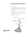
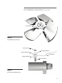
U S E R M A N UA L
Marley Ultra Quiet Fan
D E S I G N E D F O R I N D U C E D - D R A F T C O O L I N G TOW E R A P P L I CAT I O N S
M2012-1165
I S S UE D 8 / 2012
R E A D A N D U N D E R S TAN D TH I S M AN UAL P R I O R TO O P E RATI N G OR S E RVI C I N G T H I S PR O D U CT.
safety and handling considerations
Safety
Warning
Because of the potential for property damage and/or danger to
person(s), it is critical to follow the proper selection, installation and
operating procedures.
Exposed rotating devices are potentially dangerous and can cause
injury or death. They must be guarded in compliance with OSHA, ANSI
and all other local standards for the specific application.
All personnel must follow applicable work safety standards, such
as Lockout/Tagout procedures while working in or around power
transmission devices.
Handling Considerations
1—Marley Ultra Quiet Fans are designed and manufactured to be very durable.
They can provide years of service if handled properly.
2—Minor aesthetic imperfections, such as surface abrasions or scuffs may be
present from manufacturing or handling and will not affect performance.
Heavy, concentrated impacts may cause gouges, penetration or dents in
the blades. If any damage is observed, the fan should not be placed into
service. Only SPX Cooling Technologies, Inc. Engineering is authorized to
evaluate any issues exceeding the above description of minor aesthetic
imperfections.
3—The entire fan assembly should be inspected periodically or after any changes
to the drive system components.
3
fan components
Fan Hub
Fan Blade
Direction of
Rotation
Trailing
Edge
Leading
Edge
Figure 1
Typical Fan Assembly
Order No.________________________________________
Trial Pitch Angle___________________________________
Final Pitch Angle__________________________________
Speed-rpm_______________________________________
Contract hp______________________________________
4
fan assembly instructions
Note
The following instructions apply to installations having straight bores or
tapered output shafts without split taper bushings.
It is convenient to preassemble the fan prior to installation on the driving
shaft.
Marley Ultra Quiet fans are statically balanced as a complete assembly.
However, the fan may be shipped unassembled. To ensure proper
re-assembly, blades and hubs are match-marked.
1—Select a large open area corresponding to the fan diameter.
2—Position the fan hub in the center of the work area with the hub taper down.
See Figure 1.
Note
Proper installation, with particular attention to tightening nuts to
the specified torque, is essential to maintain the design integrity of
these units.
3—Install one blade (with the trailing edge curved up): Clean any dirt or grease
from the rod end and the surfaces of the resilient mounts. Align the rod end
hole with the holes in the resilient mounts and insert the blade mounting
bolt (first through the resilient mount with the recess to accept the bolt
head, then through the rod end hole). See Figure 2, below. Screw the bolt
into the second resilient mount lightly. A 3/4" drive torque wrench with a
short extension may be used. The blade mounting bolt is supplied from the
factory with grease on the threads and conical face. Do NOT clean the
grease from the bolt.
Figure 2
Blade Installation
Mounting Bolt
Resilient Mount
Rod End
4—Complete the installation of one blade by holding it so that the blade extends
straight out from the hub tube. Holding the blade in this position, tighten
the bolt using a torque wrench set to 200 ft-lb (271 N·m) making
sure the rod end and the resilient mounts seat.
➠
5
fan assembly instructions
(continued)
Figure 3
Completed Blade Connection
5—Install the rest of the blades so that they are identical with the first blade.
See Figure 3, above, for completed blade connection. Torque all bolts
to 200 ft-lbs (271 N·m). If blades are installed properly, they will return to
their undisturbed position if the tips are pressed in the axial direction with
moderate force (10 to 20 lb).
6
fan installation instructions
(refer to Figure 4)
1—Be sure motor is locked out.
2—Clean the hub bore and driving shaft extension for the full length of the key.
3—Insert the key in the keyway. The top of the key must be below the top of the
shaft by not more than 1/8" (3mm). The key is a tight fit across the width
and must never be altered.
4—After cleaning, apply a coat of anti-seize compound to the engagement
portion of the shaft.
5—Raise the fan assembly above the shaft and slowly lower the hub onto the
shaft with the keyways aligned. Make certain the key does not slide down
during installation.
6—Tighten 2 set screws to 30 ft-lb (41 N·m) over key.
Fan Retention Bolt
Retention Washer
Hub
(shown without blade
spokes for simplicity)
Set Screws
Key
Fan Shaft
Figure 4
Hub to Shaft Assembly
7
fan installation instructions
(continued)
7—Install the hub retention cap screw with lock washer. Torque hub retention
cap screw to 50 ft-lb (68 N·m). If the standard hub retention cap screw is
too short, locate longer cap screw in the Fan Retention Hardware Kit, along
with new retention washer.
8—After installing the fan, manually rotate it while moving the blade tips up and
down to be sure they clear the ring or throat at all points. When a blade is
held in alignment with the blade tube (that is, straight outward from the hub),
it should clear the fan ring by a distance adequate to provide for any relative
motion between the fan wheel and the ring. Excess clearance between the
blade tips and the ring however, should be avoided to prevent backflow,
which seriously reduces fan efficiency. If clearance is excessive, the diameter
may be adjusted at this time. See "adjust diameter" section on page 11.
9—Install air seal per instructions below.
Air Seal Installation
The air seal disc is a thin sheet metal disc. The installation of this disc is required
to prevent the back flow of air through the center of the fan to maximize the fan’s
efficiency. See Figure 5, on following page.
1—Locate the air seal installation hardware in the plastic bag taped to one of
the hub tubes.
2—Install the air seal studs on the appropriate side of the hub tube (air seal may
be installed on either side of hub). Finger tighten.
3—Place one resilient washer on each stud as shown in Figure 6, on following
page.
4—Place the air seal onto the studs and install the remaining hardware, following
the sequence shown in the drawings. Do not lubricate this end of the studs.
5—Note that the diameter of the resilient washers, before they are compressed, is
slightly less than the diameter of the aluminum washer. Tighten each nut until
the resilient washer's diameter is the same as the aluminum washer. Do not
over tighten. Over tightness exists when the resilient washer has expanded
in diameter larger than the diameter of the aluminum washer.
8
fan installation instructions
(continued)
Air Seal Disc
Figure 5
Assembled Ultra Quiet Fan
Aluminum Nut
Resilient Washer
Aluminum Washer
Air Seal Disc
Resilient Washer
Air Seal Stud
Figure 6
Air Seal and Hardware Items
9
adjust blade angle
(if required)
Hubs are shipped from the factory with the rod end set for the blade angle
indicated by the design performance. A change in blade angle is sometimes
necessary however, to adjust to actual site conditions. Failure to adjust the
blade angle when required may result in blade overload. To adjust, loosen the
clamp nut just enough to allow the blade to be turned. Place an inclinometer
on the flat surface of the root section as shown below in Figure 7. Turn the
blade until the desired angle is achieved. Make a permanent record of the final
angle selected and take care that all blades on the fan are set at the same
angle. A typical adjustment may be +/- 3°.
Caution
The fan is designed to consume the horsepower stated on the Fan
Specification Sheet. Too great an increase in blade angle can cause
serious blade overload which will stall the blades. In this condition, the
fan will actually deliver less air and blade life may be shortened.
The maximum recommended blade angle is 30°. Retighten the clamp
nut to 200 ft-lbs (271 N·m). Recheck each blade angle after tightening.
Clamp Nut
Figure 7
Pitch Measurement Location
10
Heavy dotted line
indicates location for
measuring blade angle.
adjust diameter
(if required)
At times it may be necessary to adjust the fan diameter to suit a particular fan
cylinder ring. The tip clearance of the blades should be in the range of the fan
diameter as listed in Table 1, below. (Use Figure 8 for reference.) If the tip
clearance is found to be outside of this range the fan diameter can be adjusted.
First remove the fan blade. Then, loosen the clamp nut so that the rod end can
be rotated in the hub tube. One complete revolution will increase or decrease
the radius of the fan by .079" (2mm). Take care that the clevis is returned to
the exact factory-set angle unless it is intended that the blade loading be
changed as discussed in the previous section. A match mark may be made at
a point on the threads and the tube before turning to assure that exactly one
revolution is made. Tighten the clamp nut to 200 ft-lbs (271 N·m). Maximum
adjustment possible is about +/- 0.75" (19mm) radially (1 1/2" on diameter).
At least 1 1/2" (38mm) of rod end threads must remain in the tube (rod end
threads must fully engage tube threads). Repeat adjustment for all fan blades
so that the tip clearance is within the listed range.
Table 1
Blade Tip Clearance
Fan Diameter (ft)
A
5
3/8" (10mm)
5 1/2
3/8" (10mm)
6
3/8" (10mm)
7
7/16" (11mm)
9
1/2" (13mm)
10
5/8" (16mm)
11
5/8" (16mm)
12
11/16" (17mm)
A
Fan Cylinder
±1/8" (± 3mm)
Fan Blade
Figure 8
Blade Tip Clearance
11
fan maintenance and service
Maintenance
Preventative maintenance will prolong useful life and assure continued troublefree operation. After the first week and subsequently at six month intervals:
• Torque all hardware to specifications referenced in this manual.
• V
isually inspect the fan for airborne debris damage, contact with fan cylinder
segments and corrosive attack. Correct any situations determined detrimental
to fan operation.
• Remove any accumulated scale or dirt.
• Clear blade drain holes at fan tip.
Service
Proper identification of your fan is necessary to ensure you receive correct
replacement parts. The Marley cooling tower serial number can be used to
determine the fan and any components installed and maintained as original
equipment on a Marley cooling tower. Please provide the Marley sales
representative the necessary information when ordering replacement fans or
components.
Replacement of individual fan blades may require rebalancing the entire fan.
If rebalancing is desired, contact the Marley sales representative in your area.
12
motor load
The corrected horsepower should be close to but not exceed the contract
horsepower specified by SPX Cooling Technologies, Inc. Determine corrected
horsepower using the following equation.
Actual volts and amperage must be obtained with the fan running and the
specified rate of water flowing over the tower after the motor and drive system
have reached operating temperature (approximately 30 minutes of operation).
HPC =
VOLTSA × AMPSA × DENSITYD
VOLTSN × AMPSN × DENSITYA
HPC
= Corrected Horsepower
VOLTSN
= Nameplate Volts
VOLTSA
AMPSA
= Actual Volts
AMPSN
= Nameplate Amperage
= Actual Amperage
HPN
= Nameplate Horsepower
DENSITYA = Actual Air Density
Note
× HPN
DENSITYD = Design Air Density
Measurements taken on motors operating with Variable Frequency
Drive controls may read up to 15% high from errors in measuring the
approximated sine wave. Instruments capable of measuring a squared
off wave form accurately should be used for measuring power in this
situation.
Do not start the motor more than four to five times per hour (each low
speed start and each high speed start count as one start).
13
parts list
Dwg. Description
No.
5
6
9
10
7
11
8
12
3
1
2
4
13
14
Note
14
1
16MM ALUMINUM NUT
2
ALUM FLAT WASHER
3
5/8" RESILIENT WASHER
4
16MM AIR SEAL STUD
5
ALUMINUM BLADE BOLT (9'-14' FAN DIA.)
5
ALUMINUM BLADE BOLT (5'-8' FAN DIA.)
6
CLEVIS CLAMP BOLT (9'-14' FAN DIA.)
6
CLEVIS CLAMP BOLT (5'-8' FAN DIA.)
7
SS FLAT WASHER (9'-14' FAN DIA.)
7
SS FLAT WASHER (5'-8' FAN DIA.)
8
CLEVIS CLAMP NUT (9'-14' FAN DIA.)
8
CLEVIS CLAMP NUT (5’-8' FAN DIA.)
9
MAG ROD END (9'-14' FAN DIA.)
9
MAG ROD END (5'-8' FAN DIA.)
10 MAG CLEVIS CLAMP (9'-14' FAN DIA.)
10 MAG CLEVIS CLAMP (5'-8' FAN DIA.)
11 GRDR-2000 SHAFT ADAPTOR
11 GRDR-2200 SHAFT ADAPTOR
11 GRDR-2400 SHAFT ADAPTOR
11 GRDR-3000 SHAFT ADAPTOR
12 1.5" SS SHOULDER BOLT (6)
13 SS SET SCREW (2) (9'-14' FAN DIA.)
14
SS SET SCREW (2) (5'-8' FAN DIA.)
When ordering parts, always provide the
cooling tower serial number and when
possible, the fan serial number from a decal
located on the fan hub.
Marley Ultra Quiet Fan
D E S IG N E D FOR I N D UCE D-D RAFT
C O O L I N G TOW E R A P P L I CAT I O N S
SPX COOLING TECHNOLOGIES, INC.
7401 W 129 ST
OVERLAND PARK, KANSAS USA
P: 913 664 7400
F: 913 664 7439
[email protected]
spxcooling.com
In the interest of technological progress, all products are subject to design and/or material change without notice.
ISSUED 8/2012
M2012-1165
COPYRIGHT © 2012 SPX Corporation