1
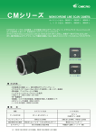
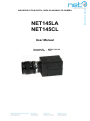
NET145LA
NET145CL
User Manual
Document ID
Revision code
NET New Electronic Technology GmbH
[email protected]
www.net-gmbh.com
NET Italia S.r.l.
[email protected]
www.net-italia.it
: NET03-0105-00
: 1.0C
NET USA, Inc.
[email protected]
www.net-usa-inc.com
NET Japan Co., Ltd.
[email protected]
www.net-japan.com
NET 145CL/LA Manual
HIGH-RESOLUTION DIGITAL AREA SCAN B&W CCD CAMERA
ii
NET145LA/NET145CL User’s Manual Rev1.0C
Table of Contents
IMPORTANT INFORMATION ..................................................................................................... V
WARNING .........................................................................................................................................V
PRECAUTIONS ..................................................................................................................................V
LIMITED WARRANTY ......................................................................................................................V
DISCLAIMER ....................................................................................................................................V
COMPLIANCE STATEMENTS FOR CE, FCC, MIC ................................................................V
1. INTRODUCTION ......................................................................................................................... 1
1.1 OVERVIEW .................................................................................................................................. 1
1.2 FEATURES ................................................................................................................................... 1
1.3 APPLICATIONS ............................................................................................................................ 1
2. HARDWARE SETUP................................................................................................................... 2
2.1 CONTENTS OF THE CAMERA PACKAGING ..................................................................................... 2
2.2 ACCESSORIES FOR SETUP (OPTION) ............................................................................................. 2
2.2.1
2.2.2
2.2.3
2.2.4
2.2.5
2.2.6
2.3
2.4
2.5
2.6
RS-644/LVDS Cable or CameraLink Cable .................................................................................................... 2
RS-232 Cable .................................................................................................................................................. 2
Power Cable .................................................................................................................................................... 2
Power Supply, PS low noise, low ripple and quality stabilized PS may be used. ............................................ 2
Popular frame grabber.................................................................................................................................... 2
Lens ................................................................................................................................................................. 2
EXTERNAL DESCRIPTION ............................................................................................................ 2
DIMENSIONS ................................................................................................................................ 6
IMAGER SPECTRAL SENSITIVITY CHARACTERISTICS ................................................................... 7
SETUP.......................................................................................................................................... 7
2.6.1 Setup Configuration ........................................................................................................................................ 7
2.6.2 Camera setup .................................................................................................................................................. 7
2.6.3 Installation for RS-232 Control Program ........................................................................................................ 8
3. CAMERA FUNCTIONS .............................................................................................................. 9
3.1 SHUTTER ..................................................................................................................................... 9
3.1.1 Normal Shutter Mode ...................................................................................................................................... 9
3.1.2 Random Shutter Mode ..................................................................................................................................... 9
3.1.3 Shutter Function .............................................................................................................................................. 9
3.2 VERTICAL SYNC RESET ............................................................................................................... 9
3.2.1 When reset ........................................................................................................................................................ 9
3.3 TRIGGER TTL / TRIGGER LVDS ................................................................................................. 9
3.4 SAVE TO EEPROM ..................................................................................................................... 9
4. DIGITAL AND FUNCTIONAL TIMING ............................................................................... 10
5. SERIAL PROTOCOL AND COMMAND ............................................................................... 12
5-1 PROTOCOL ................................................................................................................................ 12
5.2 COMMAND ................................................................................................................................ 12
5.2.1 Command Format ......................................................................................................................................... 12
5.2.2 Command List ........................................................................................................................................... 13
5.3 COMMAND DESCRIPTION .......................................................................................................... 13
5.4 DATA TRANSMIT AND RECEIVE ................................................................................................. 15
6. FRAME GRABBER SETUP ..................................................................................................... 15
© 2004 NET GmbH. All rights reserved
NET145LA/NET145CL User’s Manual Rev1.0C
iii
6.1 METEOR-II/DIG (FOR NET145LA) ........................................................................................... 15
6.1.1
6.1.2
6.1.3
6.1.4
6.1.5
FG Installation .............................................................................................................................................. 15
DCF Copying ................................................................................................................................................ 15
Start Intellicam .............................................................................................................................................. 15
Start DCF ...................................................................................................................................................... 15
Continuous Grab ........................................................................................................................................... 15
6.2 DIFFERENT FRAME GRABBER ................................................................................................... 16
8. TROUBLESHOOTING ............................................................................................................. 17
8.1 COMMON SOLUTIONS ................................................................................................................ 17
9. TECHNICAL SUPPORT INFORMATION ............................................................................ 17
Figure List
FIGURE 1. PARTS DESCRIPTION ............................................................................................. 2
FIGURE 2. POWER AND TRIGGER CONNECTOR ........................................................................ 3
FIGURE 3. SERIAL CONNECTOR ............................................................................................. 3
FIGURE 4. DATA CABLE CONNECTOR ..................................................................................... 4
FIGURE 5. NORMAL SHUTTER SPEED ..................................................................................... 5
FIGURE 6. IMAGER SPECTRAL SENSITIVITY CHARACTERISTICS ................................................. 7
FIGURE 7. SYSTEM CONFIGURATION ...................................................................................... 7
FIGURE 8. DIGITAL INTERFACE TIMING .................................................................................. 11
FIGURE 9. SERIAL COMMAND LIST ........................................................................................ 13
• AFTER BOOTING, THE CAMERA SETS DATA OF [0]. ................................................................. 13
FIGURE 10. RANDOM SHUTTER LIST………..……………………………………………………………….14
FIGURE 11. CAMERA SPECIFICATIONS.................................................................................... 16
© 2004 NET GmbH. All rights reserved
iv
NET145LA/NET145CL User’s Manual Rev1.0C
Important information
Before using this camera, please read the User’s Manual carefully.
The product has been safely designed to prevent malfunctions and accidents. Please observe
strictly the handling precautions below. If faults are suspected, consult the shop for NET
products nearest you without attempting to disassemble the camera yourself.
Warning
Do not remove screws or covers to prevent fire or electric shock.
Do not expose this camera to rain, directly to sunlight or moisture, nor try to operate it in
Do not attempt to remove camera cover nor modify any unit.
Warranty will be voided against the damage caused by you or any other equipment.
wet areas.
Precautions
Do not attempt to disassemble, modify, or repair the camera.
If you need, please contact New Electronic Technology.( “NET”) for help.
Do not directly shoot sunlight or strong spotlight to the camera for a long period.
It may cause CCD blooming and permanent damages.
Do not operate the camera beyond the temperature range and avoid using the camera
over 90% humidity.
Do not use unregulated power supply source.
Do not clean CCD faceplate with fingers or any hard objects other than Lens tissue or a
cotton tipped applicator and ethanol.
Do not use the strong or abrasive detergents when cleaning the camera body.
Limited Warranty
NET warrants only the original components to be free from defects in material for one year from the
purchasing date. This warranty covers failures or damages due to defects in material, which would occur
during normal use. It does not cover damages or failures, which result from shipment, mishandling, abuse,
misuse, or modification.
Any damage caused by improper handling will not be repaired by NET.
A Return Material Authorization (RMA) number is required prior to returning any NET product for repair or
replacement.
This proprietary document may not be reproduced or photocopied without the consent of NET, which doesn’t
make any warranty or assume or responsibility for the errors which may not appear in this document.
NET reserves the right to make changes without notice or obligation.
For technical assistance, please email to [email protected]
or [email protected]
© 2004 NET GmbH. All rights reserved
NET145LA/NET145CL User’s Manual Rev1.0C
v
Disclaimer
The information in this document has been carefully checked and is believed to be entirely reliable. However,
no responsibility is assumed for inaccuracies, nor is any responsibility assumed by NET GmbH ( “NET” ) for
its use; nor for any infringements against the patents or the other rights of the third party resulting from its
use. No license is granted under any patent or the patent rights of NET. NET points out that there is no legal
obligation to documenting internal relationships in any functional module of its products, which is realized in
either hardware or software.
NET reserves the right to make changes in specifications, functions or designs at any time and without any
notice.
NET products are not authorized for use as components in life support devices or systems intended to
surgically be implanted into the body or intended to support or sustain life Product and the company names
in this document may be the trademarks and trade-names of their respective owner and are hereby
acknowledged.
Copyright © 2004 Net GmbH
All rights reserved.
COMPLIANCE STATEMENTS for CE, FCC, MIC
To meet EC requirements, shielded cables must be connected to other devices for these cameras. These
cameras have been tested in the compliant environment of a typical class A. It is assumed that the camera
has been tested and found to comply with the limits for a Class A digital device, pursuant to Part 15 of the
FCC Rules. These limits are designed to provide the reasonable protection against harmful interference in a
residential installation. This equipment generates uses and can radiate radio frequency energy and, if not
installed and used in accordance with the instructions, may cause harmful interference to radio
communications. However, there is no guarantee that interference will not occur in a particular installation.
© 2004 NET GmbH. All rights reserved
vi
NET145LA/NET145CL User’s Manual Rev1.0C
Blank Page
© 2004 NET GmbH. All rights reserved
NET145LA/NET145CL User’s Manual Rev1.0C
1
1. Introduction
1.1 Overview
The NET145LA or NET145CL are a 1.45 Mega pixel digital camera with an EIA-644 (“LVDS”) or
CameraLink standard interface. The camera is a high resolution B/W progressive scan CCD camera.
The imager resolution is 1392 x 1040 pixels. All functions of the camera are adjusted via its digital and
serial interface. For this purpose, NET145LA/NET145CL provides a user-friendly RS-232C as external
port add to internal RS-232C, respectively.
It connects the camera ports with the serial port and frame grabber on the PC through customer’s cable.
Camera control program runs under WIN2000 / XP and gives control over the camera functions. A serial
command is possible to fully control the camera functions using the windows hyper terminal
independently. For this purpose, a well-known terminal program or any appropriate program may be used
as well.
NET145LA/NET145CL has an exclusive built-in look-up table(LUT). This can be set at externally
selectable functions such as gain, offset, shutter speed and others through the RS-232C. Details
concerning the command code can be found in the section “Serial Command”.
What is LVDS or Camera Link signal?
LVDS is a Low Voltage Differential Signaling device which extends the performance of the commonly used
RS-422 differential data bus. RS-422 limits the frequency to the 20 MHz range. However, LVDS clock
support is over 65MHz (66 MHz NSC, 65 MHz TI) and improves the signal transmission of cables with
10m to 30m lengths. It also reduces the EMI significantly. The LVDS device is now called RS-644 and is
pin-to-pin compatible with standard RS-422. If a frame grabber contains a RS-644 input, it can take both
RS-644 data and RS-422 data with extended cable length.
CameraLink standard is based on Channel Link Technology of National Semiconductor. Channel Link is
the standard and advanced concept of LVDS (Low Voltage Differential Signaling) technology for
transmitting digital data. Channel Link uses a parallel-to-serial transmitter and a serial-to-parallel receiver
to transmit data at rates up to 2.38 Gbps.
1.2 Features
2/3” Progressive Scan and interline transfer CCD Imager
1392(H) x 1040(V) effective pixels
Supports Digital RS-644(LVDS) or Camera Link
Supports 15fps full pixel and high frame rate up to 60fps as effective 256 lines
Square pixel
High sensitive and low smear
Full frame shutter from 1/15 to 1/6,000 sec
Supports random shutter
S/N ratio 50 dB or better
Asynchronous reset with external shutter control
10-bit RS-644/LVDS digital output
RS-232 external control
C-mount
1.3 Applications
Applications are machine vision, robotic control, inspection, character recognition, medical, biomedical
imaging, microscope, traffic control, surveillance, RFID and other scientific & industrial applications.
© 2004 NET GmbH. All rights reserved
2
NET145LA/NET145CL User’s Manual Rev1.0C
2. Hardware Setup
2.1 Contents of the camera packaging
•
•
•
•
NET145LA / NET145CL Camera
Lens cover
RS-232C Controller Program
User’s Manual
2.2 Accessories for setup (option)
2.2.1 RS-644/LVDS Cable or CameraLink Cable
Should be the flexible twisted pair and overall shielded cable.
2.2.2 RS-232 Cable
2.2.3 Power Cable
2.2.4 Power Supply, PS low noise, low ripple and quality stabilized PS may be used.
PS electricity requirement is 12VDC / 1A
2.2.5 Popular frame grabber
Refer to Appendix A (Compliant List)
2.2.6 Lens
C-mount Lens are available at NET GmbH / NET USA, Inc.
2.3 External Description
2
1
* Only for NET145LA
3
9
1
2
11
4
7
12
5
4
8
10
3
6
1
6
3
4
2
DC IN/ SYNC
5
5
REMOTE
POWER
Ext.sig.
6
DATA OUT
7
18
1
* NET145LA : 36 pin
* NET145CL : 26 pin
36
19
Figure 1.
Parts Description
© 2004 NET GmbH. All rights reserved
3
NET145LA/NET145CL User’s Manual Rev1.0B
Lens mount
It is suitable for various types of C mount lens.
C-mount ring can be rotated by loosing the hexagonal screws (M3:Dia 1.5mm)
Screw holes for mounting camera
Used for mounting the camera into a tripod stand, etc.
DC Power and Ext. Trigger connector
Pin No.
1
2
3
4
5
6
7
8
9
10
11
12
NET145LA
Power GND
+ 12V
A.GND
Analog Video Signal
GND
External Trigger
NC
GND
NC
GND
Strobe Pulse
GND
Pin No.
1
2
3
4
5
6
7
8
9
10
11
12
NET145CL
Power GND
+ 12V
GND
NC
GND
Rx (RS-232)
Tx (RS-232)
GND
Strobe Pulse
External Trigger
NC
GND
Figure 2. Power and Trigger Connector
• Strobe Pulse Signal : Can only be used with Random Shutter mode
1
2
9
11
4
Camera side connector : HR10-10R-12PA (Hirose)
Cable side plug
: HR10A-10P-12S (Hirose)
8
10
3
7
12
6
5
Remote and Analog video output connector (Only for NET145LA)
Below is the connector for 15 Hz non-interlaced video signal of 1 Vp-p with Sync and RS-232C
control.
Camera
Pin No.
Signal
Signal Name
COM port
of PC (DB9)
1
RX
Receive data
3
2
SG
Signal GND
5
3
VIDEO *
-
-
4
+ 10V *
-
-
5
A.GND
Analog GND
-
6
TX
Transmit data
2
Figure 3. Serial Connector
• 3 Pin(Video), 4 Pin(+10V), and 5Pin (A.GND) are used for controlling IRIS of Lens, not for RS-232C
control
1
6
5
2
3
4
Camera side connector : HR10-7R-6PA (Hirose)
Cable side plug
: HR10A-7P-6S (Hirose)
© 2004 NET GmbH. All rights reserved
4
NET145LA/NET145CL User’s Manual Rev1.0C
Power LED
When power is on, LED turns blue.
External Trigger LED
When Ext. Trigger enters the LED lights up and under regular Trigger the LED turns green. If red blinks
continuously, it indicates an error with the camera or with Ext. Trigger.
Digital video data output connector
Used for connection with the 36-pin interface cable.
Description for NET145LA
Pin No.
Signal
I/O
Pin No.
Signal
I/O
1
CLK +
O
19
D2 +
O
2
CLK -
O
20
D2 -
O
3
HD +
O
21
D3 +
O
4
HD -
O
22
D3 -
O
5
VD +
O
23
D4 +
O
6
VD -
O
24
D4 -
O
7
RX
I
25
D5 +
O
8
TX
O
26
D5 -
O
9
NC
27
D6 +
O
10
NC
28
D6 -
O
11
NC
29
D7 +
O
12
NC
30
D7 -
O
13
NC
31
D8 +
O
14
EXT TRIG
I
32
D8 -
O
15
D0 +
O
33
D9 +
O
16
D0 -
O
34
D9 +
O
17
D1 +
O
35
GND
18
D1 -
O
36
GND
Figure 4. Data Cable Connector
1) CLK
: Pixel clock output
2) HD
: Reference timing pulse output for line data
3) VD
: Reference timing pulse output for frame
4) EXT TRIG : Random shutter trigger input
1
18
1) Camera side connector : MDR 10236(LVDS)
2200VE(3M)
36
13
19
1
2) Camera side connector : MDR 102262200VE(3M)
26
14
(Camera Link)
3) LVDS Cable side plug : 10136-6000EC
© 2004 NET GmbH. All rights reserved
(3M)
5
NET145LA/NET145CL User’s Manual Rev1.0B
Description for NET145CL
Pin No.
Signal
1
I/O
Pin No.
Signal
GND
14
GND
2
TX0-
15
TX0+
3
TX1-
16
TX1+
4
TX2-
17
TX2+
5
TxClk-
18
TxClk+
6
TX3-
19
TX3+
7
SerTC+
20
SerTC-
8
SerTFG-
21
SerTFG+
9
CC1-
22
CC1+
10
NC
23
NC
11
NC
24
NC
12
NC
25
NC
13
GND
26
GND
Normal Shutter Speed Mode & Random Shutter Speed Mode
Normal Shutter Speed
Random Shutter Speed
1/15sec
1/120sec
1/30sec
1/250sec
1/60sec
1/500sec
1/120sec
1/1000sec
1/500sec
1/2000sec
1/1000sec
1/3000sec
1/2000sec
1/4000sec
1/3000sec
1/8000sec
1/4000sec
1/16000sec
1/8000sec
1/16000sec
Figure 5. Shutter Speed
© 2004 NET GmbH. All rights reserved
I/O
6
NET145LA/NET145CL User’s Manual Rev1.0C
2.4 Dimensions
Size
: 50 (W) x 50 (H) x 76 (L) mm
Weight : approx. 330gr
1
2
3
11
4
1) Camera side connector
HR10-10R-12PA (Hirose)
2) Cable side plug
HR10A-10P-12S (Hirose)
9
8
10
7
12
5
6
DC IN/ SYNC
1
6
3
4
2
REMOTE
POWER
Ext.sig.
5
1) Camera side connector
HR10-7R-6PA (Hirose)
2) Cable side plug
HR10A-7P-6S (Hirose)
DATA OUT
© 2004 NET GmbH. All rights reserved
7
NET145LA/NET145CL User’s Manual Rev1.0B
2.5 Imager Spectral Sensitivity Characteristics
Figure 6. Imager Spectral Sensitivity Characteristics
2.6 Setup
2.6.1 Setup Configuration
Cable for LVDS or Camera Link
RS-232
Ext Trigger
Ext Power
56K
PCMCIA
…. etc
INSERT THIS END
iMac
PC with Frame Grabber
(LVDS or CL)
Figure 7. System Configuration
2.6.2 Camera setup
Please connect each device correctly.
Cable connection procedure should be in the following order.
When Plug-off, the step should be reversed !
© 2004 NET GmbH. All rights reserved
8
NET145LA/NET145CL User’s Manual Rev1.0C
1) Connect one end of the data cable from FG on PC to camera connector.
1-1) Indicates the connector for outputting digital video signal
1-2) Read out 10-bit parallel signal according to EIA-644 or RS-422 specifications.
2) Connect serial cable(RS-232C) from COM Port on PC to camera connector.
(only used in case of NET145LA)
3) Connect one end of the power cable from power supply to camera connector.
3-1) Supply +12VDC power from the external DC power.
3-2) For the power supply voltage, supply the rated 12VDC. If it fluctuates, be sure to use the
voltage within the range 10VDC to 15VDC.
2.6.3 Installation for RS-232 Control Program
1)
2)
3)
4)
5)
Make any folder (ex: NET145) on your PC
Copy the RS-232 control program to your PC
This should correspond to the appearance figure shown below
Program may be different according to the camera model
Run the RS-232 Control Program
Evaluate the serial communication, shutter speed, mode setting, etc.
(Refer to the Serial Command List)
© 2004 NET GmbH. All rights reserved
NET145LA/NET145CL User’s Manual Rev1.0B
9
3. Camera Functions
3.1 Shutter
There are two modes in shutter mode such as normal mode and random mode.
3.1.1 Normal Shutter Mode
When the normal shutter is chosen, the CCD performs continuous exposure and outputs
the output video signal at real-time. Under this mode, Trigger signal is not accepted.
3.1.2 Random Shutter Mode
When input the external trigger signal, the CCD device charges and outputs rapidly the remained
electrical charge area and smear at CCD transfer area.
3.1.3 Shutter Function
The following trigger signal is not accepted within the video accumulation period after trigger
input(about 100ms after trigger is signaled).
3.2 Vertical Sync Reset
Vertical Sync Reset is only effective in Random Shutter Mode.
3.2.1 When reset
After the trigger signal input, the VD is automatically reset inside the camera.
In this case, the input of the EXT VD is not accepted.
3.3 Trigger TTL / Trigger LVDS
As described in section “Camera connectors” the cameras are equipped with two
equivalent trigger inputs. Pin 8 and 9 of the control interface utilize an opto-coupled TTL
input (TR-/+), while pin 2 and 3 of the image data interface make up an LVDS-based
trigger input. Normally, the latter is used. It is controlled via a frame grabber, which in
turn, obtains the trigger pulse from an external device (for instance a light barrier).
3.4 Save to EEPROM
Saves the current camera parameters to Camera’s EEPROM.
© 2004 NET GmbH. All rights reserved
10
NET145LA/NET145CL User’s Manual Rev1.0C
4. Digital and Functional Timing
The image data interface of NET145LA / NET145CL is LVDS or CameraLink based.
The diagram below illustrates the transfer scheme of pixels, lines and frames. Please
note that the micro timing may differ from this scheme (signal delay, flank conductance,
etc.). Nevertheless, when it comes to the adaptation of a frame grabber to the camera,
the micro timing is usually not important. The scheme is conceptually simple: The
transfer of an image starts when FVAL(VD) goes low. During this time, LVAL(VD)
goes from high to low, thus indicating the transfer of the n-th line. A corresponding low
level of PLLK will then signal a valid pixel. Please note that the first and the last pixel of
a line, as well as the first and last lines of a frame are black.
A. Continuous Shutter Operations
1) Vertical Synchronization Signal
1061
1068
VD
HD
0
19 1
Video
Out
Blanking Period
Video Signal Period
7H
12H
1040H
2) Horizontal Synchronization Signal
HD
( 1790)
0
(1790)
0
180
(1H)
400
Video
Out
Blanking Period
Video Signal Period
400T
3T
1392T
2T
3T
© 2004 NET GmbH. All rights reserved
11
NET145LA/NET145CL User’s Manual Rev1.0B
3) Pixel Clock
1CLK=35nS
Pixel Clock
Digital Data
Pixel Clock = 28.6364MHz
B. The Condition after Input Random Trigger
Random Trigger
VD
3.24ms
Strobe Pulse
Continuous shutter
mode change to
Random shutter
mode
79.8us
Exposure
Time
CCD Exposure
Period
1/500 ~1/2000 sec
Video Out
Continuous Image
58.8us
Shutter Image
Figure 8. Digital Interface Timing
© 2004 NET GmbH. All rights reserved
12
NET145LA/NET145CL User’s Manual Rev1.0C
5. Serial Protocol and Command
5-1 Protocol
Communication mode : Transmit by Full duplex serial
Data length
: 8 bits
Stop bit
: 1 bit
Parity
: None
Transmission speed
: 9600 bps
Refer to Figure3 Serial Connector about cable connection
5.2 Command
5.2.1 Command Format
Command is transferred in the following order..
[STX][CODE1][CODE2][TYPE][DATA1][DATA 2][ETX]
In the case of NET145LA,
STX = ‘\002’, ETX = ‘\003’, ACK = ‘\006’, NACK = ‘\025’
In the case of NET145CL,
STX = ‘Z’, ETX = ‘M’, ACK = ‘\006’, NACK = ‘\025’
Characters
1st character
nd
2 & 3rd character
th
5 and 6th character
Last character
Type
STX
CODE
DATA
ETX
Command
00 ~ FF
00 ~ FF
-
Remark
Start of Command
Command name
Data Value
End of Command
• It is necessary to provide a text start character control code “STX” at the beginning of
each command, and a text end character control code “ETX” at the end.
• All the alphabetic characters of each command should be in capital letters.
Use of lower case characters does not cause the command to be executed.
• All Commands should be converted to ASCII characters before sending to the camera.
• In case of transmission of an incorrect command or in the event of a communication
error, a negative acknowledge character code “NAK” will be sent back from the camera.
© 2004 NET GmbH. All rights reserved
13
NET145LA/NET145CL User’s Manual Rev1.0B
5.2.2 Command List
CODE
Command
TYPE
D
Control Item
A Description
T
A
1/120sec
1/250sec
1/500sec
1/1000sec
1/2000sec
1/3000sec
1/4000sec
1/8000sec
1/15sec
1/30sec
1/60sec
1/120sec
1/500sec
1/1000sec
1/2000sec
1/3000sec
1/4000sec
1/8000sec
ADC gain control (00 : 0dB,
FF:+24dB)
(* default : 64) XX = 0x00 ~ 0xFF)
Fine mode resolution (normal
shutter mode only)
05
05
05
05
05
05
05
05
04
04
04
04
04
04
04
04
04
04
0
1
2
3
4
5
6
7
0
1
2
3
4
5
6
7
8
9
-
06
0
XX
0E
0
-
0E
1
-
Draft mode resolution
0F
0F
0
1
-
13
0
XX
13
1
-
14
1C
1C
F
0
1
-
SAVE
F0
0
Y
LOAD
F0
1
Y
RETUTN
01
F
-
Normal shutter mode
Random shutter mode
ADC Offset control with value xx,
XX=0x00~0xFF
ADC PED control, back to factory
setting
Factory setting
Tx clock phase 0
Tx clock shift by degree of 180
- Saves the current setting value in
[Y] areas of flashrom.
- Load [Y] area value of flashrom
- Y = 0~ F
Transfer the current camera setting
value to the serial port.
R_SHUT_SPEED
N_SHUT_SPEED
GAIN
-
Fine/Draft mode
Shutter mode
OFFSET
ALL RESET
TX Clock
Figure 9. Serial Command List
• After booting, the camera sets data of [0].
5.3 Command Description
(1) R_SHUT_SPEED
Controls Random shutter speed
Example : When sets Random shutter speed to 1/120 sec
NET145LA : \002050\003
NET145CL : Z050M
© 2004 NET GmbH. All rights reserved
14
NET145LA/NET145CL User’s Manual Rev1.0C
(2) N_SHUT_SPEED
Controls Normal shutter speed
(3) GAIN
Gain can be set for the range value from 0 dB to +24 dB.
To set Gain value to +24 dB
[STX] [0] [6] [0] [F] [F] [ETX]
(4) OFFSET
The following are the control method for offset value
Offset Setting
[STX] [1] [3] [0] [X] [X] [ETX]
[X] [X] :[0] [0] ~ [F] [F]
When sets at initial factory default
[STX] [1] [3][1] [ETX]
(5) ALL RESET
All setting condition initialized.
[STX] [1] [4] [F] [EXT]
By this command, all setting conditions return to initial setting condition. Initial setting
condition means Factory setting condition.
(6) SAVE/ LOAD
Available memorized and call preset setting condition.
This command can memorize camera setting condition (max.6 modes) and possible to call.
The memory to Page-1 present setting condition
[STX] [F] [0] [0] [1] [ETX]
When call Page-2 (memorized setting condition)
[STX] [F] [0] [1] [1] [ETX]
(7) RETURN
The current camera setup data is sent from the camera to the terminal.
A.
Sending the setup data back to the camera.
[STX] [0] [1] [F] [ETX]
When the above command is accepted by the camera, the following command will
be transmitted continuously.
01F[ACK]05Y[ACK]04Y[ACK]06YY[ACK]0FX[ACK]130YY[ACK]
• [ACK] : Acknowledge control code
• X value is 0 or 1 and Y value is from 0 to 0xF
© 2004 NET GmbH. All rights reserved
NET145LA/NET145CL User’s Manual Rev1.0B
15
5.4 Data Transmit and Receive
5.4.1 Transmission and Reception
(1)
The following shows how the data is normally transmitted from the terminal and
received by the camera.
The command normally received by the camera is added with an
acknowledgement control code “ACK” and sent back to the terminal.
Example : N_SHUT_SPEED command is transmitted.
• [STX 0 A 1 ETX] is transmitted from the terminal.
• N_SHUT_SPEED switch of the camera is set to on.
• [0 4 1 ACK] is sent from the camera back to the terminal
(2)
In case in which an incorrect command (a command not covered in the list) is transmitted
from the terminal
A negative acknowledge control code [NAK] is sent from the camera back to the terminal.
(3)
Other errors
In the event that a command fails to be accepted due to occurrence of a
communication error, [NAK] is also sent back.
6. Frame Grabber Setup
6.1 Meteor-II/DIG (for NET145LA)
The bandwidth of the Meteor-II/Digital is not sufficient for the full speed mode of NET145LA.
All the other cameras may be used in Full Speed mode.
Please note that the Meteor-II/DIG works with Windows NT/2000/XP.
6.1.1 FG Installation
Please install the frame grabber Meteor-II/DIG first.
(The details of this installation are described in chapter 2 and 3 of Hardware
Installation and Installing Software of the grabbers manual.)
6.1.2 DCF Copying
Depending on the type of camera in use, you will find a CD named FOControl
shipped with camera. CD contains DCF file for the adaptation of the MeteorII/DIG to NET145LA/NET145CL. Please copy the file to a hard disk directory of your
choice.
P
6.1.3 Start Intellicam
Start the program Matrox Intellicam, to be installed with the grabber.
Please make sure that in the middle of the toolbar, MeteorII Digital Device 0 should be chosen and
displayed, which means MeteorII Digital Device 0 under the folder of MeteorII Dig of System
Delection
6.1.4 Start DCF
Exit Intellicam first and then start the DCF file.
6.1.5 Continuous Grab
Click Continuous Grab.
Window shows the free running image of the camera.
© 2004 NET GmbH. All rights reserved
16
NET145LA/NET145CL User’s Manual Rev1.0C
6.2 Different Frame Grabber
NET145LA / NET145CL can be used with other digital frame grabbers as well. However, please note
that the implementation of the cable as well as the adaptation of the frame grabber requires some
experience.
7. Camera Specification
Features
Image Device
Effective pixel
Pixel Size
Image Area
Scanning System
Frame Rate
Shutter Speed
Aspect Ratio
Lens Mount
Flange Focal Distance
Digital Interface
Gain Control
Synchronization
Gamma
Min. Illumination
S/N Ratio
Power Supply
Power Consumption
Weight
External Dimensions
Operation Temp.
Storage Temp.
NET145CL
NET145LA
2/3” CCD Sony ICX285AL
1.450.000 pixel 1392(H) x 1040(V)
6.45 µm x 6.45 µm
10.2 (H) x 8.30 (V) mm
Progressive Scan
15fps full pixel read out
20µs – 66ms
4:3
C-mount
17.526mm
Camera Link, RS-232C
EIA-644 (LVDS) or RS-422, RS232C
Auto or Manual
External Trigger
1
0.5lux @ F 1.4
50 dB or better
12VDC
500mA
approx. 330 gr.
50 (W) x 50 (H) x 76 (D) mm
-10 to + 50 0C, 20 – 90% rel., non cond. Humidity
-20 to + 60 0C, 20 – 70% rel., non cond. Humidity
Figure 10. Camera Specifications
© 2004 NET GmbH. All rights reserved
17
NET145LA/NET145CL User’s Manual Rev1.0B
8. Troubleshooting
The following information can help solving problems that may occur during the setup of
the camera. Make sure that the camera is part of the entire acquisition system
• Power supplies
• Frame grabbers H/W and S/W
• Light source
• Operation environment
• Cabling
• Host computer
• Optics
8.1 Common Solutions
The first step during troubleshooting is to verify that the camera has all the correct connections
regarding Power supply, Data cables, etc.
9. Technical Support Information
If you need technical assistance, please do not hesitate to contact NET GmbH Technical Support
NET New Electronic Technology GmbH
Lerchenberg 7
86923 Finning, Germany
Tel: +49 8806 9234 0
Fax: +49 8806 9234 77
[email protected]
www.net-gmbh.com
NET Italia S.r.l.
Via Carlo Pisacane, 9
25128 Brescia, Italy
Tel: +39 030 5237 163
Fax: +39 030 5033 293
[email protected]
www.net-italia.it
NET USA, Inc.
3037 45th Street
Highland IN 46322, USA
Tel: +1 219 934 9042
Fax: +1 219 934 9047
[email protected]
www.net-usa-inc.com
NET Japan Co., Ltd.
2F Shin-Yokohama 214 Bldg.
2-14-2 Shin-Yokohama, Kohoku-ku,
Yokohama-shi, 222-0033, Japan
Tel: +81 45 478 1020
Fax: +81 45 476 2423
[email protected]
www.net-japan.com
© 2004 NET GmbH. All rights reserved
18
NET145LA/NET145CL User’s Manual Rev1.0C
Appendix A. Compliant FG List
Manufacturer
Mutech Corp
Coreco Imaging
Euresys
Matrox Imaging
National Instruments
National Instruments
NET New Electronic Technology GmbH
Lerchenberg 7
86923 Finning, Germany
Tel: +49 8806 9234 0
Fax: +49 8806 9234 77
[email protected]
www.net-gmbh.com
Model
MV1500
X64-CL
Multi
Meteor-II / Digital
IMAQ-1422
IMAQ-1424
NET Italia S.r.l.
Via Carlo Pisacane, 9
25128 Brescia, Italy
Tel: +39 030 5237 163
Fax: +39 030 5033 293
[email protected]
www.net-italia.it
NET USA, Inc.
3037 45th Street
Highland IN 46322, USA
Tel: +1 219 934 9042
Fax: +1 219 934 9047
[email protected]
www.net-usa-inc.com
Remark
NET Japan Co., Ltd.
2F Shin-Yokohama 214 Bldg.
2-14-2 Shin-Yokohama, Kohoku-ku,
Yokohama-shi, 222-0033, Japan
Tel: +81 45 478 1020
Fax: +81 45 476 2423
[email protected]
www.net-japan.com
© 2004 NET GmbH. All rights reserved