1
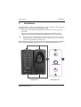
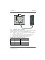
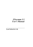
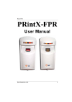
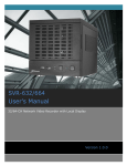
PRintX40I/V
User Manual
Synel Industries Ltd.
PRintX40I/V 30/8/04 Part no.650401 (PRintX40-222-02)
This document has been prepared for PRintX40I/V device. All rights
reserved. Reproduction or use, without express permission of editorial or
pictorial content, in any manner is prohibited. No patent liability is assumed
with respect to the use of the information contained herein. While every
precaution has been taken in the preparation of this manual, Synel Industries
Ltd. assumes no responsibility for errors or omissions. Neither is any liability
assumed for damages resulting from the use of the information contained
herein. DCM and SY are trademarks of Synel Industries Ltd. All trade names
referenced herein are either trademarks or registered trademarks of their
respective companies.
Synel Industries Ltd.
PRintX40I/V
Table of contents
Table of contents
1.
1.1
1.2
1.3
1.4
1.5
2.
2.1
3.
3.1
3.2
4.
Introduction ........................................................................1
Differences between PRintX40I & PRintX40V.................1
Technical Specifications.....................................................1
Man-machine Interface.......................................................2
Mechanical Features...........................................................2
Package...............................................................................2
Installation ..........................................................................3
Wires Connection ...............................................................5
Operation ............................................................................8
Access Control using PRintX40I/V unit ............................8
Programming Mode............................................................9
Maintenance .....................................................................16
Synel Industries Ltd.
i
PRintX40I/V
1.
Introduction
Introduction
PRintX40I/V is a biometric stand-alone controller, one of the series of
Synel’s access control protocols. It is a unit that operates with either a
fingerprint verification version - PRintX40V (catalogue number 00430) or a
fingerprint identification version - PRintX40I (catalogue number 00431)
further to user-card reading (by the proximity unit). The proximity and
biometric units are adjacently installed at sensitive locations for granting
access to secure areas. The PRintX40I/V works with various unit settings,
according to the security level required at the location of the unit. Defining
parameters is simple while maximum security is enabled by using a password
defined by the user. Access is available for upto 4000 card holders in the
verification version, and upto 200 card holders in the identification version,
stored in an authorized list. This list is created and edited using keyboard.
1.1
•
•
1.2
•
•
•
•
•
•
•
Differences between PRintX40I & PRintX40V
(PRintX40I) Identification does not require a card/code. Upto 200 fingerprint templates are stored in the terminal’s memory. Whenever an
employee places his finger on the sensor, the FP (fingerprint) unit polls
all existing templates until there is a match and confirms/rejects.
(PRintX40V) Verification requires a card/code. The template is stored in
reference to a card/code. Upto 4000 card/codes and templates are stored.
When an employee swipes his card/keys-in his code, the unit checks if
the card/code number exists, if it does it checks also the template
assigned to that number.
Technical Specifications
Maximum Range: 10 cm (4 inches)
Operating Frequency: 125 kHz
RS-232 or RS-485 (ASCII); 9600 b/s
Storage for 4000/200 templates
Sensor vendor: Bioscript
False rejection rate:0.001
False acceptance rate:0.001
Synel Industries Ltd.
1
Introduction
1.3
•
•
•
•
•
1.4
•
•
•
•
•
•
•
1.5
PRintX40I/V
Man-machine Interface
Indicator for: Power, card confirmation/rejection and keyboard entry, fingerprint (a tri-color led)
10-digit keyboard
Bell button
RF coupling of proximity card
Buzzer for audio confirmation of operations
Mechanical Features
Dimensions: 137X115X28 mm
Weight: 360gr
Operating temperature: 0 to +60°C
PRintX-40I_V Power supply: 12Vdc, 20.5A
PRintX Power supply: 5Vdc 21A
Output relay rating: 24 V @ 3 A
Tamper sensor output TTL level max @ 16 mA
Package
•
•
•
PRintX-40I_V proximity reader
PRintX/P biometric reader verification/identification
PRintX/P power supply adaptor: 5 Volt/1 A stabilized wide range input
100-240 AC input
• RJ-11 Connection box with 5V power input
• RJ-45 Connection box
• Four 3.5x50mm Philips screws, four 3.5x19mm Philips screws and four
for position B, four Brick/Plaster anchors
• Mounting template
• User manual
Recommended: PRintX-40I_V Power supply adaptor:12 to 15 Vdc, max @
880 mA
2
Synel Industries Ltd.
Installation
PRintX40I/V
2.
Installation
The PRintX40I/V readers are installed in any type of facility. The following
guidelines are to be used when installing the units:
• Keep the cable assembly separated from and at least 30 cm away from
any cable.
• Use a power adaptor dedicated to the proximity unit. Make sure the
adapter carries a safety recognition marking such as UL, CSA or CE.
Note: When using the identification feature the finger unit can be installed
outside the door and the PRX40 reader installed in the inner side of
the door (designated for setup only!).
While following step by step instructions for mounting, refer to the diagram
below and the mounting template (CAT No. 600090, MD600090-01-A):
A
B
2
1
C
B
A
Front panel
Synel Industries Ltd.
Back panel (x2)
3
Installation
PRintX40I/V
1.
Disassemble PRintX-40I_V and RJ-45 connection box wiring, in order
to route cable.
2.
Two mounting options are available for this unit:
• Option A- Mounting the assembled unit to the wall, using four
screws threaded through holes at the top and bottom of the unit (1)
• Option B - Mounting the disassembled back panel to the wall, after
concluding this procedure re-assemble unit’s front panel and
secure screws.
Option A:
Step 1.
Step 2.
Step 3.
Step 4.
Step 5.
Step 6.
Step 7.
Step 8.
Option B:
Step 1.
Step 2.
Step 3.
Step 4.
Step 5.
Step 6.
Step 7.
Step 8.
Step 9.
Step 10.
4
Remove screw covers and screws from top and bottom of the units
front panel (1).
Drill holes according to position A shown on the mounting template, for both units PRintX-40I_V and PRintX.
Route PRintX-40I_V wiring.
Place two screws in position A, one at the top position and one at
the bottom position; secure PRintX-40I_V to the wall.
Route PrintX wiring.
Slide groove on the PRintX against PRintX-40I_V slip.
Place two screws in position A, one at the top position and one at
the bottom position; secure PRintX to the wall.
Proceed according to wires connection instructions, page -5.
Remove screw covers and screws from top and bottom of the unit
front panel (1).
Remove back panel.
Drill holes according to position B shown on the mounting template, for both units PRintX-40I_V and PRintX.
Fasten back panel on the wall (2), place two short screws in position B. Secure PRintX-40I_V to the wall.
Route the cable wires via centre hole C.
Route PRintX-40I_V+PrintX wiring.
Slide groove on the PRintX against PRintX-40I_V slip.
Fasten back panel on the wall (2), place two short screws in position B. Secure PRintX to the wall.
Route the cable wires via centre hole C.
Place and secure PRintX-40I_V+PRintX front cover (2) using two
Synel Industries Ltd.
Installation
PRintX40I/V
Step 11.
2.1
short screws (position A).
Proceed according to wires connection instructions, page -5.
Wires Connection
There are three connection types:
2.1.1
PRintX-40I_V Power supply, door lock & bell connection
The PRintX-40I_V (PRX40 unit) 12 wiring connection used for the door
relay, bell and power supply control; for color codes refer to the table below.
Wire No. Wire Function
Present Color Code
1
Vin Power (VCC)
Red
2
Gnd
Black
3
- TxRx RS-485
Grey
4
+ TxRx RS-485
Purple
5
TxD RS -232
White
6
RxD RS -232
Green
7
Tamper Control
Brown
8
Normal Neutral (C)
Blue
9
Normal Close (N.C.)
Yellow
10
Normal Open (N.O.)
Orange
11
Bell (1)
Black/White
12
Bell (2)
Red/White
2.1.2
PRintX-40I_V and PRintX/P connection
Wiring instructions:
1.
Insert the PRX40’s RJ-45 connection box at its hidden position on the
wall.
2.
Connect PRintX/P unit’s flat RJ-45 connector to connection box.
Synel Industries Ltd.
5
Installation
PRintX40I/V
PRintX - RJ-45 Connection Box (reference)
Wire function
PRintX - P2
(5 Pin female)
PRintX - P3
Wire No. Connection box
(7 Pin female)
Colour Code
GND
5
1
BL
Wiegand data 1
2
2
OR
Wiegand data 0
1
3
BK
Led1
1
4
RD
Led2
3
5
GR
6
YL
Not used
3.
Connect PRintX-40I_V to RJ-45 connection box, route 5 wires as
follows:
PRX40 (J1) - RJ-45 Connection Box
PRX40
Wire Function
Cable Col- Wire
our Code
No.
GND
Black
2
OR
Wiegand data 0
Green
4
RD
Wiegand data 1
White
3
BK
LED 1
Yellow
6
YL
LED 3
Blue
7
BR
6
Connection box
Colour Code
Synel Industries Ltd.
Installation
PRintX40I/V
OR
BK
RD
GR
YL
YL
BK
WH
BL
GR
2.1.3
PRintX/P - HOST Connection
This connection provides a communication interface and power supply to
PRintX/P, whenever a host connection is required (MV1000):
Note: Commonly, this unit is unplugged from host. It is mainly plugged-in
for FPU maintenance purposes.
1.
Place RJ-11 connection box in its hidden position on the wall.
2.
Connect PRintX/P flat RJ-11 connector to connection box.
3.
Connect DC-Input jack to RJ-11 connection box.
PRintX - RJ-11 Connection box (reference)
Wire No. Wire Function
Present Colour Code
1
TXD
Blue
2
GND
Yellow
3
RXD
Green
4
NC
-
5
NC
-
Synel Industries Ltd.
7
Installation
6
8
PRintX40I/V
VCC
White
Synel Industries Ltd.
Operation
PRintX40I/V
3.
Operation
3.1
Access Control using PRintX40I/V unit
1.
2.
3.
Bring user-card within range of PRintX-40I_V (Verification only).
Place user-finger on the PRintX sensor.
Compatibility between card-user and finger-user enables access activates door relay.
4.
No compatibility between user-card and user-finger prevents access
and initiates a buzzer sound - door relay was not activated.
The PRintX/P reader allows for two basic operations:
Enrolment - is scanning a fingerprint, determining the quality of the
fingerprint scan and storing a good template as a reference (See “Managing
Access Cards or Codes” on page -13).
Verification - is proofing of the currently scanned fingerprint against the
stored fingerprint templates for that user. PRintX operates as a server,
interacts to accept PRintX-40I_V instructions. A four-mode led is designated
for status indication:.
Flashing orange
A flashing orange led indicates that the employee is
requested to place his finger for sampling purposes, while
Enrolment process is on.
Orange
Waiting for fingerprint validation, while performing verification.
Green
Successful operation.
Red
Failure.
A led is activated to indicate current status, when operation is completed the
results are transmitted to PRintX-40I_V.
Synel Industries Ltd.
9
Operation
3.2
PRintX40I/V
Programming Mode
The PRintX-40I_V divides its tasks into three categories:
1.
Management of System Tools
2.
Management of Access Cards (authorized personnel)
3.
Management of System Tasks
How to Enter programming mode?
All system management requires entering the system.
1.
Press 3 times simultaneously on function-keys 1&2 (each time will be
followed by a short beep and an orange LED will be lit).
2.
Key-in the eight digit Master-Card code (default – 12345678).
It is recommended that the client change this code later.
3.
After entering “Programming Mode” you can define parameters, as
follows:
Note: This is a continueous procedure a delay while entering parameters
will promote the Programming mode after a short time-out
10
Synel Industries Ltd.
Operation
PRintX40I/V
All definitions of Management modes are listed in the table below.
Function Description
& Glossary Number
Code
Value
Default
Remarks
Initialisation of
Memory
06
9210
Operation Mode
12
0006
0000
Card and FP
Operation Mode
12
0008
0000
Code and FP or FP only
Insert card(s) to
PRX - 40 list and
Fingerprint
20
9999
*
Delete cards from list
for PRX - 40
and fingerprint
21
8888
**
Open Door Time
10
00000225
Open Door
00
0000
Set New Master Code
13
xxxxx
xxxx
Management of
System Tools
Management of
Access Cards
(Authorized
Personnel)
Management of
System Tasks
Synel Industries Ltd.
1
0 To 25.5 Seconds
Opens the relay for Door
Open Time
123456
78
Must consist of 8 digits
11
Operation
PRintX40I/V
*
Operation mode - card and FP
Bring Card within PRintX-40I_V range. Place your finger on the PrintX
unit, you have 10 sec. to acknowledge; Press:
To insert -1
To exit - 2
Operation mode - code and FP
Key-in a 4 digit code. Place your finger on the PrintX unit, you have 10
sec. to acknowledge; Press:
To insert -1
To exit - 2
**
Operation mode - card and FP
Bring Card within PRintX-40I_V range. You have 10 Sec to acknowledge;
Press:
To delete -1
To exit - 2
Operation mode - code and FP
Key-in a 4 digit code. You have 10 sec. to acknowledge; Press:
To delete -1
To exit - 2
3.2.1
Management of System Tools
S e t N e w M a s t e r C o de
The Master Code can be changed using the “Instruction Code” – 13. After
entering “Programming Mode” key-in “13” followed by an eight digit
number that will serve as a New Master Code. It is recommended to change
the Master Code default immediately after installing the unit.
M e m o r y I n i t i a l is a t i o n
Warning: All data saved on PRintX-40I_V will be deleted.
This options deletes all cards in the memory. “Initialisation of Memory” takes
a few seconds to complete - (the green LED blinks) wait until you hear the
buzz, signifying completion.
12
Synel Industries Ltd.
PRintX40I/V
Operation
Operation Mode
Card and Finger Print (verification only)
Control is performed by Card and card holder fingerprint accepted by the
PRintX unit:
1.
Press 3 times function-keys 1&2 simultaneously. The red LED flashes.
2.
Key-in the eight digit Master-Card code (default – 1234...8).
3.
Key-in Instruction code 12 and “0006”.
Code and FP (only in PRintX40I_V - FP)
Control is performed by code and fingerprint accepted by the PRintX unit. If
the fingerprint unit is in auto-detection mode (identification) the user does not
need to Key-in the code, just place his finger on the sensor:
1.
Press 3 times function-keys 1&2 simultaneously. The red LED flashes.
2.
Key-in the eight digit Master-Card code (default – 1234...8).
3.
Key-in the instruction code 12 and “0008”.
3.2.2
Managing Access Cards or Codes
I n se r t C a r d s I n t o L i st
•
•
Cards may be entered one at a time or one directly followed by another.
When the green LED flashes, the PRintX-40I_V is ready to read cards,
the card (s) must be brought within the unit’s range.
Upon completion of card insertion, the operation is cancelled and
reverted to Programming mode after a short time-out (is if operation is
not acknowledged within 10 sec.).
Inserting cards can be performed following this procedure:
1.
Press function-keys 1&2 3 times simultaneously. The red LED flashes.
2.
Key-in the eight digit master code. You are Programming mode.
3.
Key-in the instruction code 20 and “9999”.
4.
PRintX orange LED flashes.
5.
Bring user-card within the range of the PRintX-40I_V; The PRintX’s
orange LED is illuminated.
6.
Place user-finger on PRintX sensor; green LED indicates success.
7.
You have 10 Sec to acknowledge:
• For card insertion press (1)
• For exiting press (2).
Synel Industries Ltd.
13
Operation
PRintX40I/V
I n se r t C o d e s Int o L i s t
•
Codes may be keyed-in one at a time or one directly following another.
When the green LED flashes, the PRintX-40I_V is ready to read cards,
the card(s) must be brought within range of the unit.
• Upon completion of code insertion, the operation is cancelled and promoted back to Programming mode.
Inserting codes can be performed following this procedure:
1.
Press 3 times function-keys 1&2 simultaneously. The red LED flashes.
2.
Key-in the eight digit master code. You are in Programming mode.
3.
Key-in code 20 and “9999”.
4.
PRintX orange LED flashes.
5.
Key-in the four digit user code; PRintX orange LED is illuminated.
6.
User-finger should be noe placed on PRintX sensor; green LED
indicates success.
7.
You have 10 sec. to acknowledge:
• To insert an additional card (1).
• To exit this mode press (2).
Note: In auto-detection mode there is a limit of upto 200 fingerprint template.
D e l et e C a r d ( s ) f ro m L i s t
Deleting cards can be performed following this procedure:
• Cards may be deleted one at a time or one directly following another.
When the green LED flashes, the PRintX-40I_V is ready to read cards,
the card(s) must be brought within range of the unit.
• This operation is cancelled and reverted to programming mode after a
short time-out (if the operation is not acknowledged within 10 sec).
1.
Press function-keys 1&2 3 times simultaneously. The red LED flashes.
2.
Key-in the eight digit Master-code (default – 1234...8). You have
entered programming mode.
3.
Key-in code 21, key-in the four digit Master-Card code (8888).
4.
PRintX red LED flashes.
5.
Bring User-card within range of PRintX-40I_V.
6.
You have 10 sec. to acknowledge:
• To delete an additional card press (1).
• To exit press (2).
14
Synel Industries Ltd.
PRintX40I/V
Operation
D e l et e C o d e ( s ) f ro m L i s t
Deleting cards can be performed following this procedure:
• Codes may be deleted one at a time or one directly following another.
When the green LED flashes, the PRintX-40I_V is ready to read codes,
the card(s) must be brought within the unit range.
• This operation is cancelled reverted to programming mode after a short
time-out (if operation is not acknowledged within 10 sec).
1.
Press function-keys 1&2 3 times simultaneously. The red LED flashes.
2.
Key-in the eight digit Master-code (default – 1234...8). You are in
programming mode.
3.
Key-in code 21, key-in the four digit Master-code (8888).
4.
PRintX red LED flashes.
5.
Key-in user code.
6.
You have 10 sec. to acknowledge:
• To delete an additional code (1).
• For exit mode press (2).
3.2.3
Management of System Tasks
O p en D o o r
Access can be given by using a Master Code. After keying-in “Programming
Mode,” key-in “0” six times.
O p en D o o r Tim e
It is possible to adjust the “window” of accessability during which a door
opens when accessed. For example, if only one person enters, you may decide
that 1.5 seconds is enough time for the user to open the door - but if more than
one is expected to enter, you can choose to prolong door opening time. Thus,
after entering “Programming Mode,” key-in the number “10” and then four
digits. For example if you key-in 0015, the delay time will be 1.5 seconds.
3.2.4
1.
2.
FPU operation - Instructions and regulations:
Do not use your thumb to enroll.
Place the higher joint of your finger on the ridge lock and lower your
finger onto the sensor surface (make sure all other fingers are held
straight to avoid creating an angle between the enrolled finger and the
sensor surface - incorrect positioning).
Synel Industries Ltd.
15
Operation
PRintX40I/V
3.
Touch the sensor's plastic casing (black) in order to discharge static
electricity. Keep your finger steady!
4.
Press your finger gently onto the panel, avoid excessive pressure as it
will blur the print.
5.
Make sure your finger is touching the sensor’s drive ring.
6.
Use the same finger for enrollment as well as for verification.
7.
If your finger is extremely dry, touch your forehead or the side of your
nose before placing it on the sensor.
8.
Do not use a wet/moist finger for scanning.
Note: For user’s convenience mount the terminal to a 1.3 meter height
(measured from the top end of the terminal) and at a distance of 15
cm from the right-side wall (closer to the sensor side).
16
Synel Industries Ltd.
PRintX40I/V
4.
Maintenance
Maintenance
You should always touch the conductive plastic before touching the PRintX/P
sensor in order to safely discharge any static electricity on your skin or
clothing.
Do not:
• Place the fingerprint sensor close to a heating source, such as a radiator
or hot plate
• Spill any liquids on the sensor with the exception of isopropyl alcohol.
• Subject the fingerprint sensor to heavy shocks or vibrations.
• Allow the sensor to come in contact with metallic objects.
Synel Industries Ltd.
17
Main Branch: Synel Industries Ltd. Yokneam Industrial Park, 2 Hamada St.,
POB 142, Yokneam 20692, Israel
Tel: +972-4-959 6777 Fax: +972-4-959 0729 E-mail: [email protected],
Site: www.synel-ind.com
Tel-Aviv Branch: Synel Systems Ltd. Tel: +972 9 775 0400
UK Branch: Synel Industries (UK) Ltd. Tel: +44-181-900 9991
North America Branch: Synel Systems N.A. Tel: +1-905-678 2605