1
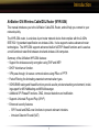
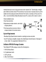
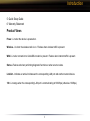
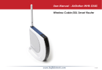
User Manual
AirStation G54
54 Mbps Wireless Cable/DSL Router
WYR-G54
Rev B
www.buffalotech.com/wireless
Table of Contents
Introduction . . . . . . . . . . . . . . . . . . . . . . . . . . . 05
Installation / Setup . . . . . . . . . . . . . . . . . . . . . . 11
Antenna Installation. . . . . . . . . . . . . . . . . . . . . . 13
Standard Settings . . . . . . . . . . . . . . . . . . . . . . . 14
AOSS Setup . . . . . . . . . . . . . . . . . . . . . . . . . . . 23
Advanced Setup . . . . . . . . . . . . . . . . . . . . . . . . 26
LAN Settings . . . . . . . . . . . . . . . . . . . . . . . . 26
Wireless Settings . . . . . . . . . . . . . . . . . . 26
Wireless LAN Security . . . . . . . . . . . . . . 28
LAN Port . . . . . . . . . . . . . . . . . . . . . . . . 32
DHCP Server . . . . . . . . . . . . . . . . . . . . . 33
Wireless MAC Filtering . . . . . . . . . . . . . 36
Wireless Bridge (WDS) . . . . . . . . . . . . . 38
WAN Settings . . . . . . . . . . . . . . . . . . . . . . . 40
WAN Port . . . . . . . . . . . . . . . . . . . . . . . . 40
WAN Network . . . . . . . . . . . . . . . . . . . . . 43
2
Table of Contents
Network Settings. . . . . . . . . . . . . . . . . . . . . 45
Routing Setup . . . . . . . . . . . . . . . . . . . . 45
Address Translation . . . . . . . . . . . . . . . . 47
Packet Filter . . . . . . . . . . . . . . . . . . . . . . 50
Intrusion Detector . . . . . . . . . . . . . . . . . 55
UPnP . . . . . . . . . . . . . . . . . . . . . . . . . . . 57
Management . . . . . . . . . . . . . . . . . . . . . . . . 58
System Information . . . . . . . . . . . . . . . . 58
Change Password . . . . . . . . . . . . . . . . . 59
Time Setup . . . . . . . . . . . . . . . . . . . . . . 60
Traffic Information . . . . . . . . . . . . . . . . . 61
Client Monitor . . . . . . . . . . . . . . . . . . . . 62
Ping Tool . . . . . . . . . . . . . . . . . . . . . . . . 63
Log Information . . . . . . . . . . . . . . . . . . . 64
Syslog Transfer . . . . . . . . . . . . . . . . . . . 65
Save/Restore Settings . . . . . . . . . . . . . . 66
Reboot/Reload Settings . . . . . . . . . . . . . 67
Firmware Updates . . . . . . . . . . . . . . . . . 68
AOSS . . . . . . . . . . . . . . . . . . . . . . . . . . . 69
3
Table of Contents
Specifications . . . . . . . . . . . . . . . . . . . . . . . . . 71
Troubleshooting . . . . . . . . . . . . . . . . . . . . . . . . 76
Glossary
. . . . . . . . . . . . . . . . . . . . . . . . . . . .84
FCC Information . . . . . . . . . . . . . . . . . . . . . . . . 90
Warranty Information. . . . . . . . . . . . . . . . . . . . . 93
Contact Information . . . . . . . . . . . . . . . . . . . . . 94
4
Introduction
AirStation G54 Wireless Cable/DSL Router (WYR-G54)
This manual introduces you to the AirStation Cable/DSL Router, and will help you connect to your
network quickly.
The WYR-G54 router, is a wireless 4-port router network device that complies with the 2.4GHz
IEEE 802.11g standard specification on wireless LANs. It also supports various advanced router
technologies. The WYR-G54 supports enhanced built-in NAT/SPI firewall functions and is used as
a multi-functional router/link between wired and wireless LAN computers.
Summary of the AirStation WYR-G54 features:
• Support for wireless security encryption using TKIP and WEP.
• DHCP client/server function.
• VPN pass-through, for secure communications using IPSec or PPTP.
• Packet Filtering for eliminating unwanted communication types.
• SOHO/SMB routing and firewall functions provide a safer private networking environment, including support for MS NetMeeting and MSN-Messenger.
• Additional SPI Firewall Functions - DMZ, intrusion detection and notification
• Supports Universal Plug and Play (UPnP).
• Enhanced security features:
- SPI Firewall and DMZ zone functions to prevent unknown intruders.
- Intrusion Detector Firewall (NAT)
5
Introduction
- Dynamic packet filtering.
- Wireless encryption via TKIP and WEP.
- VPN pass-through for IPSec and PPTP connections.
- Packet monitoring and filtering by MAC address, IP address and port.
- PPPoE support
• Buffalo’s easy web interface configuration
• Broadband router static and dynamic routing methods between WAN and LAN based on updated
routing tables. An economical way to bridge multiple networks.
• Web based setup wizards for both Cable and DSL broadband connections.
Home Networking 1
Buffalo AirStation wireless access points enable sharing broadband by simply connecting the
AirStation to a DSL or Cable modem to:
• Share files and printers
• Access and share the Internet
• Share media files
SOHO/SMB Networking
With high-speed DSL or Cable connections readily available, many users can work effectively from
a home office, connected securely to a corporate network. Buffalo’s solutions are ideal for home
6
Introduction
networks that require secure, high-speed access to the corporate LAN. Tools that play an integral
part in Buffalo’s solutions include VPN connectivity for secure access to corporate resources, which
enable the remote employee to handle information from clients or coworkers as if they were in the
office. Connect the Buffalo AirStation Broadband router AP to a Cable or DSL modem in order to:
•Share broadband access
•Share files and printers
•Bridge between multiple networks and multiple
computer platforms
•Provide easy and secure access to home or
company networks from remote locations
System Requirements
• Broadband (High-Speed) Internet connection or existing Local area connection
• Any Wi-Fi (wireless) compatible computer with a Web Browser Internet Explorer or Netscape 4.5
or later. (Safari 1.0 is supported with Macintosh OS X.2)
AirStation WYR-G54 Package Contents
The AirStation WYR-G54 package consists of the following items.
1. WYR-G54 Base Station
2. AC adapter/power cable
3. CAT5 LAN cable
4. Utility CD with Manual
7
Introduction
5. Quick Setup Guide
6. Warranty Statement
Product Views
Power - Lit when the device is powered on.
Wireless - Lit when the wireless radio is on. Flashes when wireless traffic is present.
WAN - Lit when connection to Cable/DSL modem is present. Flashes when internet traffic is present.
Status - Flashes red when performing diagnostic functions or when an error exists.
Link/Act - Indicates an active link between the corresponding LAN port and another network device.
100 - Lit orange when the corresponding LAN port is communicating at 100 Mbps (otherwise 10 Mbps).
8
Introduction
About the AirStation CD
The AirStation does not require any software to be installed on your computer for configuration.
The AirStation CD contains client drivers for Buffalo Wireless Adapters (i.e. Notebook Adapter and
Desktop PCI Adapter) and the AirStation documentation.
Prior to copying or installing any software, please read the Software License Agreement “license.
9
Introduction
txt”, located in the root folder of the CD. By installing, copying or using the AirStation software, you
are consenting to the terms of this agreement. If you do not agree to all of the terms of the Software
License Agreement, do not download, copy or install the AirStation software.
It is the policy of Buffalo Technology to improve products as new technology, components, software
and firmware become available.
Please consult the AirStation wireless website (http://www.buffalotech.com/wireless) to download
and install the latest firmware for your product.
Follow these simple steps to connect the AirStation to your Broadband Internet connection allowing
you to combine and share wired and wireless computers and printers with the high-speed internet
connection.
1. Power down the Cable or DSL modem and the computer which will be used to configure the
10
Installation / Setup
AirStation router.
2. Plug the Cable or DSL’s LAN Ethernet cable into the AirStation’s WAN port. Initially, you may
need to unplug this cable from your computer, hub or other router.
3. Plug the provided Ethernet cable into a LAN port on the AirStation and plug the other end into
your computer Ethernet adapter’s (NIC) port. If you plan to initially configure the AirStation via a
wireless connection, (not recommended), you may skip this step.
4. Power on your cable or DSL modem, wait one full minute, Power on the AirStation router, wait
another full minute and then power on the computer which will be used to configure the AirStation. If the red DIAG light on the AirStation is lit or flashing after several minutes of being powered on, please consult Buffalo Technical Support.
Introduction
Configuring the AirStation using a standard web browser requires basic wireless configuration
knowledge. Setup includes manual wireless configuration and basic administrative management.
Setup Preparation
Make note of the AirStation’s wired MAC address found on the rear of the AirStation. It is also
recommended you record any other broadband ISP information such as global IP address, subnet
mask address, default gateway address, DNS server address and PPPoE parameters.
Setup Overview
11
Installation / Setup
Buffalo recommends using a wired connection, meaning your computer is physically connected to
the AirStation with a CAT5 straight cable plugged into one of the four LAN ports This type of setup
will eliminate possible setup problems due to any issues with the wireless adapter on the computer
being used to configure the AirStation.
A Web browser version 4.5 or later can be used to configure the AirStation.
Advanced settings for security, filtering and other features will be explained in later sections.
Open the Setup Screen
• Connect the WYR-G54 according to the wiring instructions in Section 2.
• The WYR-G54 has a default LAN IP address of 192.168.11.1 and Subnet Mask of 255.255.255.0.
■ Note: The computer used to configure the AirStation should be set to obtain an IP address
automatically using a DHCP server. The Quick Setup Guide enclosed with the product contains
detailed instructions on how to configure your computer for initial configuration.
On the computer used to configure the AirStation, launch a Web Browser 4.5 or later.
- Enter 192.168.11.1 into the URL field.
- A window will open prompting you to enter a User ID and Password.
12
Antenna
The WYR-G54 has one internal omnidirectional antenna. The
transmission of wireless signals is isotropic, meaning that the
waves are emitted much like the sun distributes light in every
direction. However, connection problems can occasionally
be remedied by simply adjusting the position of the antenna.
External antennas come in all shapes and sizes. Antennas
also come with different connectors. The WHR2-G54 has an
‘MC Connector’ on it. Thus, the antenna must also have an
MC connector.
To install the antenna, slide the antenna connector door on
the back of the WYR-G54 to the right. This will expose the
MC Connector. Attaching the antenna is simple, just insert
the antenna’s MC Connector into the WYR-G54’s MC Connector and firmly push it in until it snaps into place. Once
snapped, the antenna’s connector will swivel with ease. It is
important not to push the antenna connector in at an angle.
To remove the antenna, pull the antenna connector out. It is
important not to pull the antenna connector out at an angle.
13
Logging In
Enter “root” as the User ID and leave the password field blank.
■ Note: These are the factory default settings
14
Setup Wizard - Launch
Internet Setup
Initial
Settings
Screen
• Click the Internet Setup arrow button to begin
the Internet Setup Wizard.
• Advanced users have the option of skipping
this step and begin manually configuring the
access point.
Choosing a Connection Type
Choosing a
Connection
Type
Click on the type of broadband connection your
ISP is providing.
Note:
If you are unsure of whether you are using cable
or DSL broadband, please contact your ISP.
DSL users can now skip to Page 18!
15
Setup Wizard - Setup
Cable Connection Options
Cable
Connection
Options
- Choose the type of connection configuration
as provided by your ISP
- Most Cable operators provide the first type of
configuration - Automatic (DHCP)
Automatic IP Assignment by ISP
DSL PPPoE
Settings
Screen
- Select ‘Automatic IP Assignment by ISP’ if
your ISP’s DHCP server assigns an IP address
automatically.
16
Setup Wizard - Cable
Manual Entry of IP Information
Manual IP
Address
Settings
- If your IP Information is provided by your ISP,
fields are provided to fill in the information.
- Some ISPs also require that a certain MAC
Address is used. If this is not specifically required, just use the default MAC Address.
Automatic IP
Address
Settings with
Manually Entered
DNS Settings
The IP Address is Acquired
Automatically but DNS Server Address
is Entered Manually
- If the ISP provides your IP configuration automatically, but requires manual entry of DNS
information, fields will be provided for DNS
information after an IP Address is successfully
acquired.
Cable Users can now skip to Page 19!
17
Setup Wizard - DSL
DSL Connection Options
DSL
Connection
Options
- Choose the type of connection configuration
as provided by your ISP
- Most DSL operators provide the first type of
configuration - Automatic (DHCP)
- When using a LAN connection type of DSL,
network settings are automatically delivered by
your ISP.
PPPoE Setup
DSL PPPoE
Settings
Screen
- Enter the requested information into the fields
provided. Note that DNS information is only required to complete setup if specifically required
by the ISP.
18
Setup Wizard - Line Test
Line Test
Line Test
Once the Setup Wizard is complete a line test
to the Internet will launch to verify successful
entry of settings.
If the connection fails, please verify the accuracy of the entered information with the ISP.
If the Line Test is successful, the AirStation is now finished with basic setup and client devices
should be able to connect to the Internet through the AirStation. The next step involves setting up
wireless security, which is optional.
19
Setup Wizard - Security
Wireless Security Setup
Security
Setup
Encrypting your wireless data is important to
prevent other devices from being able to monitor your wireless data transmissions.
There are two options available TKIP or WEP.
One or the other may be selected, or you can
choose not to enable security and allow open
movement of traffic.
TKIP - check with your client adapter vendors to make sure that ALL of your wireless adapters support this method of WPA encryption.
WEP - while most wireless adapters support WEP, it has been shown not to be as robust as TKIP,
though it is considered adequate for home use.
Disabled - when security is disabled, clicking Continue will return you to the Home screen where
other configurations can be made or you can Log Out of the access point and begin using your
AirStation normally.
20
Wireless Settings
Security Setup Completion
WEP Setup
TKIP Setup
- If WEP is chosen as the encryption type, you need only to enter
in an encryption key. Note that
depending on the type (ASCII vs.
HEX), the length of the key will
vary depending on the numbers
of bits in use.
- If TKIP is chosen as the encryption type, you need only to
enter a pre-shared key. Note that
depending on the type (ASCII vs.
HEX), the limitations of the key
length will vary. The rekey interval
can be left at its default settings
unless advanced configuration is
needed.
21
- Once the encryption key has been
successfully added, the AirStation
will save the key and restart. At
this point, the key will need to be
entered into any device connecting
wirelessly to pass data through the
AirStation. If problems are encountered connecting wirelessly with the
encryption key, please use a wired
connection to attempt configuration
or reset the AirStation with its reset
button on the rear face.
Wireless Settings
LAN
Settings
LAN Settings
Click on the LAN Settings button within the left frame to configure basic or advanced LAN settings.
Wireless Settings
Wireless Mode - Allows you to choose between supported rate sets.
- Mixed - supports both 11b and 11g clients (default setting)
- Turbo - supports only 11g clients. 11b clients will not be allowed to associate, thus improving
overal performance of the wireless network.
- Legacy - only 11b rates are supported. Use this for troubleshooting older wireless adapters.
22
23
Wireless Settings
SSID - Allows administrator to alter the SSID of the AirStation. To communicate with a specific AP
only, the AP’s SSID must be entered in the client computer. The client computer looks for the specific AP (or SSID) for wireless communication. Use up to 32 alphanumeric characters for the SSID
(case sensitive). By default the SSID is the LAN Mac address of the AirStation.
■ Note: Roaming - When multiple AirStations have an identical
SSID, WEP key (if WEP is used),
(and channel in WDS mode)
, client computers may Roam
between the AirStations.
Wireless
Settings
Wireless Channel - Select the
channel used for wireless communication. There are 11 overlapping channels. Channels 1, 6
and 11 are non-overlapping. The
‘Auto-Channel’ option is recommended, as it constantly assesses the best available channel for
the AirStation to operate on.
If there are multiple APs in close proximity using the same channel, there may be interference. In
this case, change to a non-overlapping channel.
Broadcast SSID - Enable or Disable the SSID (SSID) from being broadcasted. If denied, the
24
Wireless Settings
AirStation will not be found unless the specific AirStation’s SSID is entered in the client computer manually.
Wireless Radio Enabled - By default the wireless radio is turned on, however by disabling the radio, no
wireless communications can take place. Wired connections can continue uneffected though.
Access to LAN - Specific clients can be given access to the local network (LAN) by enabling this limitation. By default all clients (wired and wireless) have access to the local network resources. Local network
resources can include but are not limited to, other computers’ shared files, networked printers and scanners.
Access to WAN - Specific clients can be given access to the Internet (WAN) by enabling this limitation. By
default all clients (wired and wireless) have access to the Internet through the WAN port.
To add users to the access tables, they
must have previously connected to the
AirStation. Select the clients you wish to
limit access to and click Apply.
Choosing
Clients that
can Access
LAN or WAN
Resources
Clients can be removed from the table at
a later time if needed.
Note: Always click Apply to save your
changed settings to the AirStation.
25
Wireless Security
Wireless Security Setup
Encrypting your wireless data is important
to prevent other devices from being able to
monitor your wireless data transmissions.
Security
Setup
There are two options available TKIP or
WEP. One or the other may be selected, or
you can choose not to enable security and
allow open movement of traffic.
TKIP - check with your client adapter vendors to make sure that ALL of your wireless adapters support this method of WPA encryption.
WEP - while most wireless adapters support WEP, it has been shown not to be as robust as TKIP,
though it is considered adequate for home use.
Disabled - when security is disabled, clicking Continue will return you to the Home screen where
other configurations can be made or you can Log Out of the access point and begin using your
AirStation normally.
26
Wireless Security
Security Setup Completion
WEP Setup
TKIP Setup
- If WEP is chosen as the encryption type, you need only to enter
in an encryption key. Note that
depending on the type (ASCII vs.
HEX), the length of the key will
vary depending on the numbers
of bits in use.
- If TKIP is chosen as the encryption type, you need only to
enter a pre-shared key. Note that
depending on the type (ASCII vs.
HEX), the limitations of the key
length will vary. The rekey interval
can be left at its default settings
unless advanced configuration is
needed.
27
- Once the encryption key has been
successfully added, the AirStation
will save the key and restart. At
this point, the key will need to be
entered into any device connecting
wirelessly to pass data through the
AirStation. If problems are encountered connecting wirelessly with the
encryption key, please use a wired
connection to attempt configuration
or reset the AirStation with its reset
button on the rear face.
Advanced Settings
WAN Port Settings
WAN Port
Settings
WAN MAC Address - The WAN
Ports MAC Address occassionaly
is required to be set to a value other than the default. Only change
the value if required by your ISP.
Login Method - There are several
ways of creating a connection to
your broadband provider. In most
cases, your ISP will use a Direct
Connection, however, in some
cases PPPoE or IP Unnumbered
is used which will require the
entering of information provided by your ISP. If you are unsure of which to use, please contact your
ISP.
28
Advanced Settings
Direct Connection Options
- IP Address and DNS Server
Address settings may have
been provided by your ISP. If
this is the case, they should be
entered here, otherwise leave
the default settings in place to
acquire these settings automatically via DHCP.
Direct
Connection
Options
29
PPPoE Client Options
PPPoE Client Options - If you are
using PPPoE for your broadband connection, your ISP should have given
some custom information to enter. If
you do not have this information, it will
be necessary to collect it from them.
PPPoE Client
Options
The connection can be set to the following types:
Connection on Demand - The connection is opened when activity is
detected and terminated after a set
period of inactivity (20 minutes by
default).
Manual Connection - The connection
must be manually started and stopped.
Continuous Connection - The AirStation will keep the connection alive indefinitely.
PPPoE Multisession - The AirStation supports PPPoE Multisession as well. If your class of broadband requires this information, hit the Multisession to enter the information in a separate window.
Make sure to hit Apply when the data entry is complete.
The MTU value (578-1492) should only be changed if specifically instructed to by your ISP.
30
Advanced Settings
Remote Management - When
enabled, remote management
will allow you to configure your
access point remotely over the
Internet. A port should be specified between the ranges of 1 and
65535.
WAN
Network
Settings
The management interface can
then be accessed by your IP Address as shown and the port as
in http://244.244.222.130:10500
where 244.244.222.130 is the
WAN IP Address and 10500 is
the specified port.
Reply to Ping from WAN Port - When the AirStation is set to respond to Ping requests, it will
acknowledge its IP Address and various other information from over the Internet. This is useful to
managing remote access points and ensuring uptime, but it can be considered a security breach as
well as it does distribute some minimal information about your router. At the minimum, make sure
you have changed your root (administrator) password with either of these functions enabled.
31
Dyanmic DNS
Dynamic DNS is useful to allow
your AirStation to respond to
requests for a domain name
such as www.yourname.com or
mail.yourname.com.
Dynamic DNS
Due to the fact that many ISPs
use DHCP rather than fixed IP
Addresses, hosting services
like web servers, game servers,
FTP servers or mail servers
can be very challenging. DDNS
provides a solution.
Entry ways for several third
party services are included on
your access point.
While each has been prescreened for compatibility and customer service, Buffalo Technology USA
can not provide adquate technical support for these services. For complete support and setup procedures, please visit the website of the service of your choosing.
32
Routing Information
RIPv1 Routing - RIP dyanmic
routing allows routing information to be shared with out ther
routers using RIPv1 routing.
This will allow easy sharing of
information between multiple
routers in regards to their own
resources or stored entries
within their routing tables. This
improves the overall performance within a complex set of
separate networks.
Routing
Information
Static Routes - Static routes can be added to the routing table to facilitate routing amongst
devices. By entering the necessary IP Information about a property and a metric to specify the required number of hops between routers to reach a device, the most efficient path can be calculated
among multiple routers. The values entered for the IP Address, Subnet Mask and Gateway should
be the IP information of the remote network device that is being routed to by the AirStation.
33
Address Translation
Address Translation (NAT)
Address Translation
Bridging PPPoE and
VPN Pass-Through
PPPoE Bridging - If a device
on the LAN Ports is capable
of managing PPPoE client
communications, enabling this
option will allow the device the
necessary direct, pass-through
access to the WAN port.
VPN Pass-Through - If you
have client devices that will
need to create VPN tunnels
with IPSec or PPTP, this option
should not be disabled. It is
enabled by default.
34
Address Translation
In some situations, it is benDemilitarized
eficial to have a client network
Zone Client
device designated as a catchall, with all ports opened to
enable better functionality
with services like messaging
or gaming.
Using a Demilitarized zone
will allow one local network
device to be exposed to the
Internet for use of a specialpurpose service such as
Internet gaming or videoconferencing. DMZ hosting
forwards all the ports at the same time to the selected device.
Packet Filtering is more secure as it only opens the ports designated to be opened, while a Demiliatrarized Zone will open every port of a designated device.
35
Network Address Translation
NAT by Service and Device
Address
Translation
by Service
Some of the common services
that address translation is
necessary to use with are offered
preconfigured.
By selecting a service, most
fields will be autofilled to make
setup easier, however if you are
using a service different from
what is offered or with different
configurations, you can a a new
service by clicking the Add New
Server button.
Be sure to accurately enter the
appropriate settings and clicking
the appropriate network device
from the Local Client Server dropdown list while it is connected to
the AirStation.
36
Packet Filtering
The AirStation supports the TCP and
UDP protocols for Network Address
Translation.
Packet
Filtering
Packet Filtering
Packet Filtering configures advanced
public services on your local network,
such as web servers, FTP servers,
email servers, gaming servers or other specialized Internet services that
require delivery of specific requests
through the router to the appropriate
local network device for delivering
specific appication requests.
When unique requests for a particular
response are delivered to your router
via the Internet, the router will forward those requests to the designated local network device for
appropriate response.
Because when DHCP is in use, IP Addresses could change for a client device over time, it is best
practice to assign local network devices that have packet filtering rules assigned to them to use a
fixed IP Address to prevent failures due to a change in IP Address that the packet filter does not
acknowledge.
37
Advanced Settings
Intrusion
Detector
Intrusion Detector
There are three levels for Intrusion
Detector to function at.
High: Recommended for Internet
bandwidth of 2 Mbps or higher.
Medium: Recommended for
Internet bandwidth between 1 and
2 Mbps bandwidth.
Low: Recommended for bandwidth under 1 Mbps.
Because your AirStation uses
an SPI Firewall, it is important to
temper your security level to your
broadband connection speed.
Even at the Low setting, your AirStation will provide an ample amount of security for your network.
38
UPnP
UPnP Service
UPnP Service
Enabling the UPnP Service
enables other UPnP enable
devices to easily regonize and
configure one another according to the developing UPnP
standard.
Note: If IP-Unnumbered
configuration is in use for DSL
connections, UPnP should not
be enabled to prevent conflicts.
39
System Information
System Information
System
Information
Firmware Version - Displays
the current firmware version
running on the AirStation.
DHCP - Displays whether the
AirStation is operating as a
DHCP client on its WAN port.
The amount of time left on
the DHCP lease is shown as
well as the ability to have the
AirStation release and renew
its current IP configuration on
the WAN port.
LAN/WAN -Various details
about the IP configuration and
MAC Addressing information
is shown about the LAN and
WAN ports.
The connection method of the
WAN port and the status of that
connection is displayed as well.
40
Basic Settings
Basic Settings
Basic
Settings
The AirStation is configured with an administrator account named root. It can
not be changed to another name.
The default password of the AirStation
is blank (i.e. no text). This value can and
should be changed.
The new password should be 8 alphanumeric characters long and can include
an underscore character ( _ ). The password is case sensitive.
If the password is forgotten, it will be
necessary to reset the AirStation via the
Reset button on the rear face, which will
cause all other configurations to restore
to factory defaults.
41
Advanced Settings
Client Monitor
Client
Monitor
Client Monitor allows you to view
the currently connected clients.
While DHCP clients are shown
automatically, it is necessary to
manually add clients with fixed
IP Addresses in order for them to
appear in Client Monitor
By clicking Detailed PC Settings
a new window will appear where
you can manually fix what IP
Address is assigned to DHCP
clients. This is useful for managing multiple DHCP clients that
will have the same IP Address at
each connection.
42
Diagnostics
Diagnostics
The Diagnostics screen allows
you to perform some basic connectivity troubleshooting. A local
or external IP Address can be
entered and checked for connectivity by clicking Ping.
Diagnostics
The results from the Ping will
show whether external or internal
connectivity is present to a client
device or remote resource from
the router. This is useful to confirm that a connectivity problem
exists on a client rather than on the router.
Also, to check name resolution via DNS, a domain name can be entered. The results will show the
IP Address of the domain name if successful. A failure could indicate an error in the DNS Server
entries for the router that should be confirmed with your ISP.
43
Log Information
Log Information
Log
You can specify the types of events Information
that are recorded into the log for
later viewing.
Internet Connection - Logs successes for failures when connecting
externally via the WAN port.
Access Restrictions - Logs successes or failures of clients connecting via the LAN port.
Intrustion Detector - Logs possible
malicious attacks that are blocked by the Intrusion Detector firewall
Note: To add value to the recorded logs, be sure to set your time zone accurately.
44
Save or Restore Settings
Save or
Restore
Settings
Save Settings - Your current settings can be saved as an image file
that can be restored to your AirStation at a later date. This is also
useful for easily setting up multiple
AirStations with identical settings.
Restore Settings - If a settings
file was previously created, it can
be quickly restored to the AirStation. Note that the settings file will
overwrite all current settings when it
is restored.
45
Restore Defaults
Restart
Restart or
Restore
Settings
Occasionally it may be necessary to restart your AirStation.
Often the first start in troubleshooting a problem is to simply
restart the device.
Restore Factory Defaults
To return the AirStation back
to its original out of the box
configuration, click the Restore
button. All changes will be lost,
so it is best practice to create a
saved settings file in advance.
46
Advanced Settings
Buffalo Technology USA regularly provides firmware updates to enhance performance, provide
additional features and to fix bugs. Please check
our website listed below for udpates.
Firmware updates should be done with a wired
connection as opposed to wirelessly. Also, it is
best practice to save your current settings to a
saved settings file in advance.
Please review the release notes to see if a firmware update is necessary. Your current update
version can be found in the System Information
section of your management screen.
Use of firmware outside of the geographic
region that the AirStation is being used in may be a violation of your country or state laws.
To update your firmware download the image from our website. Then unzip the package if necessary to a known location on your computer. Click the Browse button and point it at the image file.
Then click Update to proceed. The AirStation will restart after the process is complete and normal
operation should resume.
Firmware updates can be found for the USA and Canada only at:
http://www.buffalotech.com/support/downloads.php
47
Troubleshooting
Common Problems:
• Out of range, client cannot connect to the AirStation.
• Configuration mismatch, client cannot connect to the AirStation.
• Absence or conflict with the Client Driver.
• Conflict of another device with the AirStation hardware.
Status LED Lit Red
Unplug the power for three seconds. Plug the power back in to monitor the DIAG LEDs during start-up.
If any symptoms match section B.1.1, call the Buffalo Tech Support line 24 hours a day, 7 days a week
at 866-752-6210 or email [email protected] for USA and Canada only.
Table B.1.1 DIAG LED Activity Table
DIAG LED Display
Time
Description/Action
Continuous Red
Starting
RAM Error Red flash, 2 times Starting Flash ROM
Error
Red flash, 3 times
Starting
A problem on the wired LAN side
Red flash, 4 times
Starting
A problem on the wireless LAN side
B. 1.2 LEDs Work But Client PC Cannot Connect to Network
48
Troubleshooting
If the LEDs indicate that the network is working properly (Power LED is on, Transmit/Receive LED
blinks), check the TCP/IP settings of the network.
Changing Client TCP/IP Settings in Windows
Consult the LAN Administrator for TCP/IP settings.
To add or change the TCP/IP Settings:
1. On the Windows task bar click Start.
2. Select Settings, then Control Panel.
3. Double-click on the Network icon to view the Network Properties.
4. From the list of installed components, verify the TCP/IP => wireless LAN adapter protocol is
installed.
• If the wireless adapter protocol is not yet installed, click the Add button and select the TCP/IP
protocol from the list. Refer to Windows Help for more information.
• If the wireless adapter protocol is installed, select the protocol and click the Properties button.
Verify the parameters match the settings provided by your LAN Administrator. Make changes
if necessary, and click OK.
5. When or if prompted, restart your computer.
B. 1.3 Other Problems
Please refer to www.buffalotech.com for further reference materials.
49
Glossary
10BaseT or 100BaseTx: 802.3 based Ethernet network that uses UTP (Unshielded twisted
pair) cable and a star topology. 10 is 10 Mbps
and 100 is 100 Mbps.
Cross-Over Wiring: A UTP cable that has its
transmit and receive pair crossed to allow communications between two devices.
802.1x: The standard for wireless LAN authentication used between an AP and a client. 802.1x
with EAP will initiate key handling.
Ad-Hoc Network: The wireless network based
on a peer-to-peer communications session.
Also referred to as AdHoc.
DCE (Data Communications Equipment):
Hardware used for communication with a Data
Terminal Equipment (DTE) device.
Default Gateway: The IP Address of either the
nearest router or server for the LAN.
Default Parameter: Parameter set by the
manufacturer.
Bandwidth: The transmission capacity of a
computer or a communication channel, stated in
Megabits per second (Mbps).
Destination Address: The address portion of
a packet that identifies the intended recipient
station.
BSS (Basic Service Set): An 802.11 networking framework that includes an Access Point.
DHCP (Dynamic Host Configuration Protocol): Based on BOOTP, it uses a pool of IP
addresses, which it assigns to each device connected to it, and retrieves the address when the
device becomes dormant for a period of time.
Bus Mastering: A system in which the specified Input/Output device (e.g. NIC Card) can
perform tasks without the intervention of the
CPU.
DNS (Domain Name System): System used
to map readable machine names into IP addresses
Client: A PC or workstation on a network.
50
Glossary
Driver: Software that interfaces a computer
with a specific hardware device.
Ethernet cable: A wire similar to telephone
cable that carries signals between Ethernet
devices.
DSSS (Direct Sequence Spread Spectrum):
Method of spreading a wireless signal into wide
frequency bandwidth.
File and Print Sharing: A Microsoft application
that allows computers on a network to share
files and printers.
DTE (Data Terminal Equipment): Device that
con10BaseT or 100BaseTx: 802.3 based
Ethernet network that uses UTP (Unshielded
twisted pair) cable and a star topology. 10 is 10
Mbps and 100 is 100 Mbps.
Firmware: Programming inserted into programmable read-only memory, thus becoming a
permanent part of a computing device.
Frame: A fixed block of data, transmitted as a
single entity. Also referred to as packet.
Dynamic IP Address: An IP address that is
automatically assigned to a client station in a
TCP/IP network, typically by a DHCP server.
Full-Duplex: To transmit on the same channel
in both directions simultaneously.
ESS (Extended Service Set): A set of two
or more BSSs that form a single sub-network.
SSID is user identification used in the ESS LAN
configuration.
Half-duplex: To transmit on the same channel
in both directions, one direction at a time.
Hub: A device which allows connection of computers and other devices to form a LAN.
Ethernet: The most widely used architecture
for Local Area Networks (LANs). It is a sharedmedia network architecture. The IEEE 802.3
standard details its functionality.
IEEE (Institute of Electrical and Electronics
Engineers): The professional organization
which promotes development of electronics
technology.
51
Glossary
IP (Internet Protocol) Address: A unique 32binary-digit number that identifies each sender
or receiver of information sent in packets.
Mbps (Mega Bits Per Second): A measurement of millions of bits per second.
MDI/X (Media Dependent Interface/Crossover): Port on a network hub or switch that
crosses the incoming transmit lines with the
outgoing receive lines.
Infrastructure: A wireless network or other
small network in which the wireless network
devices are made a part of the network through
the Access Point.
MHz (MegaHertz): One million cycles per
second.
ISP (Internet Service Provider): A company
that provides access to the Internet and other
related services.
IV (Initialization Vector): The header section
of an encrypted message packet.
NAT (Network Address Translation): An internet standard that enables a LAN to use one set
of IP addresses for internal traffic and a second
set for external traffic.
LAN (Local Area Network): A group of computers and peripheral devices connected to
share resources.
NIC (Network Interface Card): An expansion
card connected to a computer so the computer
can be connected to a network.
LED (Light Emitting Diode): The lights on
a hardware device representing the activity
through the ports.
Packet: A block of data that is transferred as a
single unit, also called a frame or a block.
Packet Filtering: Discarding unwanted network traffic based on its originating address or
its type.
MAC (Medium Access Control) Address:
A unique number that distinguishes network
cards.
52
Glossary
PCI (Peripheral Component Interconnect): A
bus that is connected directly to the CPU.
mation between computers.
RADIUS (Remote Authentication Dial In User
Service): A server that issues authentication key to
clients.
PCMCIA (Personal Computer Memory Card
International Association) Card: Removable module that adds features to a portable
computer.
RAM (Random Access Memory): Non-permanent
memory.
Ping (Packet Internet Groper): An Internet
utility used to determine whether a particular IP
address is online.
Repeater Hub: A device that collects, strengthens
and transmits information to all connected devices,
allowing the network to be extended to accommodate additional workstations.
Plug and Play: Hardware that, once installed (“plugged in”), can immediately be
used (“played”), as opposed to hardware that
requires manual configuration.
RC4: The encryption algorithm that is used in WEP.
RJ-45 connector: An 8-pin connector used between a twisted pair cable and a data transmission
device.
PoE (Power over Ethernet): A mechanism
to send DC power to a device using a CAT5
Ethernet cable.
ROM (Read Only Memory): Permanent memory.
Router: Device that can connect individual LANs
and remote sites to a server.
PPPoE (Point-to-Point Protocol over Ethernet): A specification for connecting users on an
Ethernet line to the Internet through a common
broadband medium.
Roaming: The ability to use a wireless device while
moving from one access point to another without
losing the connection.
Protocol: A standard way of exchanging infor53
Glossary
Script: A macro or batch file containing instructions and used by a computer to perform a task.
TCP/IP (Transmission Control Protocol/Internet Protocol: Protocol used by computers
when communicating across the Internet or
Intranet.
Server: Any computer that makes files or
peripheral devices available to users of the
network and has a resident Network OS.
TKIP (Temporal Key Integrity Protocol): An
encryption method replacing WEP. TKIP uses
random IV and frequent key exchanges.
SMTP (Simple Mail Transfer Protocol): The
protocol used to define and deliver electronic
mail (E-mail) from one location to another.
Topology: The shape of a LAN (Local Area
Network) or other communications system.
SNMP (Simple Network Management Protocol: An application layer protocol that outlines
the formal structure for communication among
network devices.
Twisted Pair: Cable that comprises 2 or more
pair of insulated wires twisted together.
UDP (User Datagram Protocol): A communication method (protocol) that offers a
limited amount of service when messages are
exchanged between computers in a network.
UDP is used as an alternative to TCP/IP.
Static IP Address: A permanent IP address is
assigned to a node in a TCP/IP network. Also
known as global IP.
STP (Shielded Twisted Pair): Twisted Pair
cable wrapped in a metal sheath to provide extra protection from external interfering signals.
Uplink: Link to the next level up in a communication hierarchy.
Subnet Mask: An eight-byte address divided
into 4 parts separated by periods.
UTP (Unshielded Twisted Pair) cable: Two or
more unshielded wires twisted together to form
a cable.
54
Glossary
WAN (Wide Area Network): A networking system covering a wide geographical area.
WEP (Wired Equivalent Privacy): An encryption method based on 64 or 128-bit algorithm.
Web Browser: A software program that allows
viewing of web pages.
Wi-Fi (Wireless Fidelity): An organization that
tests and assures interoperability among WLAN
devices.
Wire Speed: The maximum speed at which a
given packet can be transferred using Ethernet
and Fast Ethernet standard specifications.
WLAN (Wireless LAN): A LAN topology using
wireless devices.
VPN (Virtual Private Network): A security
method to connect remote LAN users to a corporate LAN system.
55
FCC / CE Information
Federal Communication Commission Interference Statement
This equipment has been tested and found to comply with the limits for a Class B digital device,
pursuant to Part 15 of the FCC Rules. These limits are designed to provide reasonable protection
against harmful interference in a residential installation. This equipment generates, uses and can
radiate radio frequency energy and, if not installed and used in accordance with the instructions, may
cause harmful interference to radio communications. However, there is no guarantee that interference
will not occur in a particular installation. If this equipment does cause harmful interference to radio
or television reception, which can be determined by turning the equipment off and on, the user is
encouraged to try to correct the interference by one of the following measures:
• Reorient or relocate the receiving antenna.
• Increase the separation between the equipment and receiver.
• Connect the equipment into an outlet on a circuit different from that to which the receiver is connected.
• Consult the dealer or an experienced radio/TV technician for help.
FCC Caution: To assure continued compliance, (example - use only shielded interface cables when
connecting to computer or peripheral devices). Any changes or modifications not expressly approved
by the party responsible for compliance could void the user’s authority to operate this equipment.
This device complies with Part 15 of the FCC Rules. Operation is subject to the following two conditions:
(1) This device may not cause harmful interference, and (2) this device must accept any interference
received, including interference that may cause undesired operation.
56
FCC / CE Information
IMPORTANT NOTE:
Federal Communication Commission Interference Statement
This equipment has been tested and found to comply with the limits for a Class B digital device,
pursuant to Part 15 of the FCC Rules. These limits are designed to provide reasonable protection
against harmful interference in a residential installation. This equipment generates, uses and can
radiate radio frequency energy and, if not installed and used in accordance with the instructions, may
cause harmful interference to radio communications. However, there is no guarantee that interference
will not occur in a particular installation. If this equipment does cause harmful interference to radio
or television reception, which can be determined by turning the equipment off and on, the user is
encouraged to try to correct the interference by one of the following measures:
-Reorient or relocate the receiving antenna.
-Increase the separation between the equipment and receiver.
-Connect the equipment into an outlet on a circuit different from that
to which the receiver is connected.
-Consult the dealer or an experienced radio/TV technician for help.
This device complies with Part 15 of the FCC Rules. Operation is subject to the following two conditions:
(1) This device may not cause harmful interference, and (2) this device must accept any interference
received, including interference that may cause undesired operation.
FCC Caution: Any changes or modifications not expressly approved by the party responsible for
compliance could void the user’s authority to operate this equipment.
57
FCC / CE Information
FCC RF Radiation Exposure Statement:
This equipment complies with FCC radiation exposure limits set forth for an uncontrolled environment.
This equipment should be installed and operated with minimum distance 20cm between the radiator &
your body. This transmitter must not be co-located or operating in conjunction with any other antenna
or transmitter.
BUFFALO declared that WYR-G54 is limited in CH1~11 by specified firmware controlled in USA.
Safety
This equipment is designed with the utmost care for the safety of those who install and use it.
However, special attention must be paid to the dangers of electric shock and static electricity when
working with electrical equipment. All guidelines of this manual and of the computer manufacturer
must therefore be allowed at all times to ensure the safe use of the equipment.
EU Countries intended for use
The ETSI version of this device is intended for home and office use in Austria, Belgium, Denmark,
Finland, France (with Frequency channel restrictions), Germany, Greece, Iceland, Ireland, Italy,
Luxembourg, Norway, The Netherlands, Portugal, Spain, Sweden, Switzerland and United
Kingdom.
The ETSI version of this device is also authorized for use in EFTA member states Iceland,
Liechtenstein, Norway and Switzerland.
EU Countries Not intended for use
None.
Potential restrictive use
France: Only channels 10,11,12, and 13.
58
Warranty Information
Buffalo Technology (Melco Inc.) products comes with a two-year limited warranty from the date of
purchase. Buffalo Technology (Melco Inc.) warrants to the original purchaser the product; good operating condition for the warranty period. This warranty does not include non-Buffalo Technology (Melco
Inc.) installed components. If the Buffalo product malfunctions during the warranty period, Buffalo
Technology/(Melco Inc.) will, replace the unit, provided the unit has not been subjected to misuse,
abuse, or non-Buffalo Technology/(Melco Inc.) authorized alteration, modifications or repair.
All expressed and implied warranties for the Buffalo Technology (Melco Inc) product line including,
but not limited to, the warranties of merchantability and fitness of a particular purpose are limited in
duration to the above period.
Under no circumstances shall Buffalo Technology/(Melco Inc.) be liable in any way to the user for
damages, including any lost profits, lost savings or other incidental or consequential damages arising
out of the use of, or inability to use the Buffalo products.
In no event shall Buffalo Technology/(Melco Inc.) liability exceed the price paid for the product from
direct, indirect, special, incidental, or consequential damages resulting from the use of the product, its
accompanying software, or its documentation. Buffalo Technology/(Melco Inc.) does not offer refunds
for any product.
@ 2004 Buffalo Technology (Melco, Inc.)
59
Contact Information
ADDRESS
Buffalo Technology (USA), Inc.
4030 West Braker Lane, Suite 120
Austin, TX 78759-5319
GENERAL INQUIRIES
Monday through Friday
8:30am-5:30pm CST
Direct: 512-794-8533 | Toll-free: 800-456-9799 | Fax: 512-794-8520 | Email: sales@buffalotech.
com
TECHNICAL SUPPORT
North American Technical Support by phone is available 24 hours a day, 7 days a week. (USA and
Canada).
Toll-free: (866) 752-6210 | Email: [email protected]
* When operating in High-Speed Mode, this Wi-Fi device achieves an actual throughput of up to 34.1 Mbps, which is the
equivalent throughput of a system following 802.11g protocol and operating at a signaling rate of 125 Mbps.
60
4030 W. Braker Ln. Suite 120
Austin, Texas 78759
Tel: 800-456-9799
Fax: 512-794-8606
Technical Support is available 24 hours a day, 7 days a week
(USA / Canada)
Toll-Free: 866-752-6210
email: [email protected]
©2004, Buffalo Technology (USA), Inc.
61