1
User Manual for the
HEC-GV3-DN Option Card
REVISION PAGES ATTACHED
AT END OF MANUAL.
DeviceNet Network Communication
Option Board for use with
Reliance Electric GV3000 AC Drive
Third Edition
22 September 1998
MAN0096-03
PREFACE
22 SEPTEMBER 1998
PAGE 2
PREFACE
This manual explains how to use the Horner Electric’s DeviceNet Network Communication Option
Board for use with Reliance Electric GV3000 AC Drive.
Copyright (C) 1998 Horner Electric, Inc., 640 North Sherman Drive Indianapolis, Indiana 46201.
All rights reserved. No part of this publication may be reproduced, transmitted, transcribed, stored
in a retrieval system, or translated into any language or computer language, in any form by any
means, electronic, mechanical, magnetic, optical, chemical, manual or otherwise, without the prior
agreement and written permission of Horner Electric, Inc.
All software described in this document or media is also copyrighted material subject to the terms
and conditions of the Horner Software License Agreement.
Information in this document is subject to change without notice and does not represent a
commitment on the part of Horner Electric, Inc.
DeviceNet is a registered trademark of Open DeviceNet Vendor Association, Inc. (OVDA)
GV3000 and Reliance are registered trademarks of Reliance Electric Company or its
subsidiaries.
For user manual updates, contact Horner Electric Advanced
Products Group, Technical Support Division, at (317) 916-4274 or
visit our website at www.heapg.com.
PAGE 3
22 SEPTEMBER 1998
PREFACE
LIMITED WARRANTY AND LIMITATION OF LIABILITY
Horner Electric, Inc. ("HE") warrants to the original purchaser that DeviceNet Network
Communication Option Board (HEC GV3000 DN) for use with Reliance Electric GV3000 AC Drive
manufactured by HE is free from defects in material and workmanship under normal use and
service. The obligation of HE under this warranty shall be limited to the repair or exchange of any
part or parts which may prove defective under normal use and service within two (2) years from
the date of manufacture or eighteen (18) months from the date of installation by the original
purchaser whichever occurs first, such defect to be disclosed to the satisfaction of HE after
examination by HE of the allegedly defective part or parts. THIS WARRANTY IS EXPRESSLY IN
LIEU OF ALL OTHER WARRANTIES EXPRESSED OR IMPLIED INCLUDING THE
WARRANTIES OF MERCHANTABILITY AND FITNESS FOR USE AND OF ALL OTHER
OBLIGATIONS OR LIABILITIES AND HE NEITHER ASSUMES, NOR AUTHORIZES ANY
OTHER PERSON TO ASSUME FOR HE, ANY OTHER LIABILITY IN CONNECTION WITH THE
SALE OF THIS DeviceNet Network Communication Option Board for use with Reliance Electric
GV3000 AC. THIS WARRANTY SHALL NOT APPLY TO THIS DeviceNet Network
Communication Option Board for use with Reliance Electric GV3000 AC Drive OR ANY PART
THEREOF WHICH HAS BEEN SUBJECT TO ACCIDENT, NEGLIGENCE, ALTERATION,
ABUSE, OR MISUSE. HE MAKES NO WARRANTY WHATSOEVER IN RESPECT TO
ACCESSORIES OR PARTS NOT SUPPLIED BY HE. THE TERM "ORIGINAL PURCHASER",
AS USED IN THIS WARRANTY, SHALL BE DEEMED TO MEAN THAT PERSON FOR WHOM
THE OPERATOR CONTROL STATION IS ORIGINALLY INSTALLED. THIS WARRANTY SHALL
APPLY ONLY WITHIN THE BOUNDARIES OF THE CONTINENTAL UNITED STATES.
In no event, whether as a result of breach of contract, warranty, tort (including negligence) or
otherwise, shall HE or its suppliers be liable of any special, consequential, incidental or penal
damages including, but not limited to, loss of profit or revenues, loss of use of the products or any
associated equipment, damage to associated equipment, cost of capital, cost of substitute
products, facilities, services or replacement power, down time costs, or claims of original
purchaser's customers for such damages.
To obtain warranty service, return the product to your distributor with a description of the
problem, proof of purchase, postage paid, insured and in a suitable package.
ABOUT PROGRAMMING EXAMPLES
Any example programs and program segments in this manual or provided on accompanying
diskettes are included solely for illustrative purposes. Due to the many variables and requirements
associated with any particular installation, Horner Electric cannot assume responsibility or liability
for actual use based on the examples and diagrams. It is the sole responsibility of the system
designer utilizing DeviceNet Network Communication Option Board for use with Reliance Electric
GV3000 AC Drive to appropriately design the end system, to appropriately integrate the Reliance
Electric GV3000 AC Drive and to make safety provisions for the end equipment as is usual and
customary in industrial applications as defined in any codes or standards which apply.
Note:
The programming examples shown in this manual are for
illustrative purposes only. Proper machine operation is the
sole responsibility of the system integrator.
PREFACE
22 SEPTEMBER 1998
PAGE 4
TABLE OF CONTENTS
PREFACE..................................................................................................................................... 2
LIMITED WARRANTY AND LIMITATION OF LIABILITY .............................................................. 3
ABOUT PROGRAMMING EXAMPLES ......................................................................................... 3
TABLE OF CONTENTS................................................................................................................ 4
SAFETY NOTICES....................................................................................................................... 6
CHAPTER 1: INTRODUCTION................................................................................................... 8
1.1
General........................................................................................................................... 8
1.2
Product Description......................................................................................................... 8
1.3
Additional Information ..................................................................................................... 9
1.4
Electronic Data Sheet (EDS) File .................................................................................... 9
CHAPTER 2: DEVICENET OVERVIEW ..................................................................................10
2.1
DeviceNet Interface Specifications.................................................................................10
2.2
Introduction to DeviceNet...............................................................................................10
CHAPTER 3: INSTALLATION.....................................................................................................12
3.1
General..........................................................................................................................12
3.2
Installing the Network Communication Option Board......................................................12
3.2.1
Safety Notices.........................................................................................................12
3.2.2
Procedures..............................................................................................................13
3.3
Connecting the GV3000 Controller to a DeviceNet Network ...........................................18
CHAPTER 4: SETUP..................................................................................................................20
4.1
General..........................................................................................................................20
4.2
Network Communication Parameters .............................................................................20
4.3
Diagnostic LEDs ............................................................................................................21
4.4
Drive Operation Parameters ..........................................................................................21
CHAPTER 5: NETWORK PROGRAMMING ...............................................................................22
5.1
Drive Data Registers Overview ......................................................................................22
5.1.1
General...................................................................................................................22
5.1.2
Input Data Update Response...................................................................................22
5.1.3
Output Data Update Response................................................................................23
5.1.4
Limitation on Data Registers Accessible (Basic/Extended) ......................................23
5.1.5
Input Data Transfer Conditions................................................................................23
5.1.6
Output Data Transfer Conditions.............................................................................24
5.1.7
Data Transfer Summary..........................................................................................24
5.1.8
Tune/Config Transfer Synchronization Flag ............................................................25
5.1.9
Parameter Processing Error Flag ............................................................................26
5.1.10 Data Retention Timing Requirements......................................................................26
5.1.11 Inaccessible Drive Parameters (Keypad Only parameters)......................................27
5.2
Building Network Messages ...........................................................................................27
5.2.1
General...................................................................................................................27
5.2.2
Loss-of-Communications Considerations.................................................................28
5.2.3
Poll Connection Data ..............................................................................................28
5.2.4
Bit-Strobed Connection Data...................................................................................30
5.2.5
Explicit Connection Data .........................................................................................31
APPENDIX A: ACCESS TO DRIVE DATA REGISTERS.............................................................32
A1 DRIVE STATUS....................................................................................................................32
A1.1.
General ......................................................................................................................32
A1.2 Drive Control..................................................................................................................32
A1.2.1 General...................................................................................................................32
A1.2.2 Register 32: Drive Control Word ............................................................................33
A1.2.3 Register 33: Network Speed/torque Reference.......................................................33
APPENDIX B: CONFIGURING DRIVE WITH DEVICENET MANAGER......................................34
B1
DEVICENET MANAGER ...................................................................................................34
PAGE 5
22 SEPTEMBER 1998
PREFACE
B1.1 General..........................................................................................................................34
B1.2 Installation of EDS file....................................................................................................34
B1.3 Adding a GV3000 Device to a Project ............................................................................36
B1.4 Configuring a GV3000 Device........................................................................................38
B1.4.1 Display Configuration ..............................................................................................38
B1.4.2 Off-line/On-line Configuration .................................................................................38
B1.4.3 Display Groups (Current/Preload)............................................................................38
B1.4.4 Modifying a (Preload) parameter .............................................................................39
B1.4.5 Loading Preloaded Parameters to Drive..................................................................39
APPENDIX C: DEFAULT TUNE/CONFIGURATION REGISTERS..............................................41
PREFACE
22 SEPTEMBER 1998
PAGE 6
SAFETY NOTICES
a.
DANGER
Only qualified electrical personnel familiar with the construction and operation of this
equipment and the hazards involved should install it. Read and understand this manual in
its entirety before proceeding. Failure to observe this precaution could result in severe
bodily injury or loss of life.
b.
DANGER
The user is responsible for conforming to the nec/cec and all other applicable local codes.
Wiring practices, grounding, disconnects, and overcurrent protection are of particular
importance. Failure to observe this precaution could result in severe bodily injury or loss
of life.
c.
DANGER
Do not install modification boards with power applied to the controller. Disconnect and
lock out incoming power before attempting such installation. Failure to observe this
precaution could result in severe bodily injury or loss of life.
d.
WARNING
Only qualified individuals who are thoroughly familiar with the particular application may
install, operate and maintain this equipment. Before any work is performed, read and
understand this instruction manual as well as the appropriate drive instruction manual(s).
Failure to observe this precaution could result in severe bodily injury.
PAGE 7
22 SEPTEMBER 1998
THIS PAGE INTENTIONALLY LEFT BLANK
PREFACE
CH. 1: INTRODUCTION
22 SEPTEMBER 1998
PAGE 8
CHAPTER 1: INTRODUCTION
1.1
General
Horner Electric’s DeviceNet Network Communication Option Board (M/N 2DV3000) allows a
Reliance GV3000 AC Drive to be upgraded with DeviceNet capability. This Option Board
functions as DeviceNet “slave” node and provides the GV3000 with the ability to communicate
over a DeviceNet network with a host of industrial control products. Both control and/or
monitoring are easily accomplished through a DeviceNet Scanner (master) residing in a PLC or
some other control device.
The option board mounts below the regulator board inside the GV3000 controller and connects to
the regulator board through an an existing flexible ribbon cable parallel-bus port. Power for the
option board comes from the GV3000 controller power supply.
In normal operation, the drive can be completely controlled via the network option board. In
many applications, there may be only a network interface connection, hard-wired emergency
stop (function loss input), and three-phase input and output power wiring. Start, stop, fault code
retreival and complete control can be accomplished over the DeviceNet network.
1.2
Product Description
The mechanical and electrical characteristics of the DeviceNet Network Communication Option
Board are described as follows:
a.
Mechanical Description
The DeviceNet Network Communication Option Board is a printed circuit assembly that mounts
inside a GV3000 Controller. It connects to the regulator board within the controller via a ribbon
cable. It has a standard DeviceNet 5-pin "pluggable" screw-terminal connector which is used to
connect a DeviceNet cable (dual twisted pairs with shield).
b.
Electrical Description
The DeviceNet Network Communication Option Board contains its own microprocessor. The
microprocessor connects to one port of the board's dual port memory while the other port
interfaces to the GV3000 regulator. The board contains a watchdog timer which is enabled when
power is turned on the the controller. The microprocessor must reset the watchdog timer within a
specified period or the microprocessor will shut down and result in an "F-60" code on the
GV3000 controller's front-panel display.
At power-up, the microprocessor will run diagnostics on the CPU, EPROM, RAM, serial I/O and
dual port memory. If there is a fault during diagnostics, an "F-60" error will be logged.
PAGE 9
1.3
22 SEPTEMBER 1998
CH.1: INTRODUCTION
Additional Information
The user must be familiar with all of the manuals that describe the system configuration which is
used. This may include, but is not limited to, the following:
a. D2-3323
GV3000 AC General Purpose (Volts/Hz) and Vector Duty Drive Software Startup
and Reference Manual Version 4.0
b. D2-3323
Installing and Operating the Three-Phase Input Three-Phase Output GV3000 AC
V*S Drive.
c. D2-3324
GV3000 AC Power Modules Hardware Reference, Installation and
Troubleshooting 1-150 HP @ 380-460 VAC Version 4.0 (or later)
1.4
Electronic Data Sheet (EDS) File
Provided with the network option card is a diskette containing an Electronic Data Sheet. This
Electronic Data Sheet is a formatted data file which provides configuration data for use with a
DeviceNet configuration utility such as DeviceNet Manager. Such configurations provide the
end user with a convenient method of configuring remote DeviceNet devices while on-line.
CH. 2: DEVICENET
22 SEPTEMBER 1998
PAGE 10
CHAPTER 2: DEVICENET OVERVIEW
2.1
DeviceNet Interface Specifications
a. DeviceNet Compliance:
Conforms to DeviceNet standard Volume I Rel 1.3 and Volume II Rel. 1.2.
Group 2 Server Only - Supporting Explicit, Poll and Bit-Strobed I/O connections.
Generic Profile.
Node Isolation consuming bus power only for communications isolation.
Pluggable bus connector.
Keypad configurable Mac Id (no default can be established).
Keypad configurable Baud rate (no default can be established).
b. Network Power Consumption:
Each option card requires a maximum of 95mA @ 11VDC of DeviceNet network power for the
transceiver circuit. Input voltage range is from 11VDC to 24VDC.
c. Connections:
Explicit message
Poll message
Bit-Strobe message
Note:
Produced
32 bytes (max)
18/30 bytes*
0 bytes
Consumed
36 bytes (max)
6/46 bytes* tt
1 bit tt
*Poll message size has two selectable sizes to meet specific application.
ttZero Length Consumed packet is defined for Poll and Strobe message.
d. Configuration:
The GV3000 may be configured conventionally through the attached keypad or remotely through
the DeviceNet network.
An EDS file is provided such that DeviceNet configuration tools (i.e., DeviceNet Manager) may be
used to configure the device. (Note: Access to the first 64 drive registers only.)
2.2
Introduction to DeviceNet
DeviceNet™ is a high-speed, twisted pair + power pair + shield network primarily used to retrieve
low-level I/O data. In addition to accessing I/O, the network can be used to configure and modify
operation of a remote node. By conforming to the DeviceNet specification, low-level devices
from multiple venders can co-exist on the same network and be accessed from the same highlevel device.
A DeviceNet network can support up to 64 nodes on a single network. Baud rates of 125K,
250K, and 500Kbaud can be selected based on the total span of the network. The network is
typically configured in a trunkline-dropline, which allows node removal without terminating the
network. The network requires resister termination at both ends of the trunkline.
PAGE 11
22 SEPTEMBER 1998
CH. 2: DEVICENET
Typical DeviceNet installations require a high-level device or master to access the data from
low-level devices. Low-level devices, which simply control local hardware, are usually Group-2Only Server devices. A Group-2-Only-Server device provides the protocol services of the
Predefined Master/Slave Connection Set. While DeviceNet provides many connections and
services, the Predefined Master/Slave Connection Set provides a limited and known subset of
services which are sufficient yet simple to access through most DeviceNet Scanners. Since a
Group-2-Only-Server has predefined connections, it does NOT support the Unconnected Message
Manager (UCMM).
The Master is a high-level device, which is used to establish communication, initiate
communication and transfer data with the low-level slave devices. A scanner is a type of master
which is used to access data from a slave device in real-time. Other masters may also exist such
as a device which is used as a low-level device configuration tool (i.e. DeviceNet Manager). A
low-level device which supports Group-2-Only-Server services can only be connected to one
master at a time.
The typical connections provided by a Group-2-Server-Only devices are Explicit, Poll and BitStrobed. The Explicit connection provides both visible and hidden services. Explicit services
which are visible to the user usually provide low priority access to a device’s parameters (run-time
or configuration) which are accessible over the network. Explicit hidden services are used by the
master for network management such as to establish other services such as the Poll and BitStrobed connections. A Poll connection is a higher priority and high-speed connection that moves
a small set of I/O data on a consistent basis. A Bit-Strobed connection is a higher priority
connection that broadcasts bit-packed control information in one packet for all low-level devices
on the network. Each device will uniquely own one bit in that packet which is usually used for
network synchronization (Start/Stop). A device may also return a small packet of high priority
response data to a Bit-Strobe broadcast.
Generally data on each connection can be sent or received. The data a device sends is refered to
as Produced data and that received as Consumed data. With Poll or Bit-Strobed connections, the
size of a produced and consumed data packet are not necessarily equal but are consistant and
must be known in advance to configure the master device. The device manufacture will provide
data tables describing both the produced and consumed data packet size, and location of each
variable in its associated packet.
CH. 3: INSTALLATION
22 SEPTEMBER 1998
PAGE 12
CHAPTER 3: INSTALLATION
3.1
General
Chapter Three describes how to install the DeviceNet Network Communication Option Board into
the GV3000 controller and how to connect the controller to a DeviceNet network.
3.2
Installing the Network Communication Option Board
3.2.1
Safety Notices
a.
DANGER
Only qualified electrical personnel familiar with the construction and operation of this
equipment and the hazards involved should install it. Read and understand this manual in
its entirety before proceeding. Failure to observe this precaution could result in severe
bodily injury or loss of life.
b.
DANGER
The user is responsible for conforming to the nec/cec and all other applicable local codes.
Wiring practices, grounding, disconnects, and overcurrent protection are of particular
importance. Failure to observe this precaution could result in severe bodily injury or loss
of life.
c.
DANGER
Do not install modification boards with power applied to the controller. Disconnect and
lock out incoming power before attempting such installation. Failure to observe this
precaution could result in severe bodily injury or loss of life.
d.
WARNING
Only qualified individuals who are thoroughly familiar with the particular application may
install, operate and maintain this equipment. Before any work is performed, read and
understand this instruction manual as well as the appropriate drive instruction manual(s).
Failure to observe this precaution could result in severe bodily injury.
PAGE 13
3.2.2
22 SEPTEMBER 1998
CH. 3: INSTALLATION
Procedures
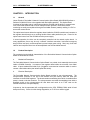
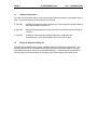
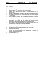
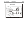
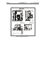
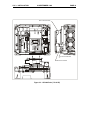
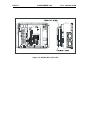
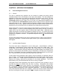
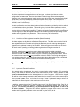
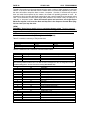
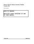
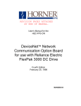
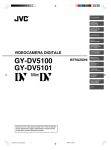
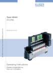
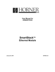
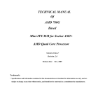
3.2.2.1 Use the following procedure to install the Network Communication Option Board. Refer to
Figures 3.1 – 3.4 for mounting locations.
1.
2.
3.
4.
5.
6.
7.
8.
9.
10.
11.
12.
13.
Disconnect and lock out all incoming power to the GV3000 controller
Loosen the four (4) captive screws at the corners of the GV3000 controller cover and
remove the cover.
Disconnect the ribbon cable that runs between the right side of the regulator board and the
daughter board from the connector on the daughter board.
If the controller is equipped with a fan, disconnect the fan power leads from the connector
on the power board.
Remove the three (3) screws that fasten the stand-off bracket (to which the regulator
board and keypad are mounted) to the controller base, and remove the regulator
board/keypad/bracket assembly from the controller.
Invert the regulator board/keypad/bracket assembly so that the keypad is on the bottom.
The ribbon cable that connects to the daughter board will extend from the left of the
regulator board and the ribbon cable that connects to the DeviceNet Network
Communications Option Board will extend from the right of the regulator board.
Connect the ribbon cable that extends from the right side of the regulator board to the
connector on the DeviceNet Network Communication Option Board.
Mount the DeviceNet Network Communication Option Board to the underside of the standoff bracket. Use the two (2) M3 self-tapping screws and lockwashers (provided) on the
right side. Use the two (2) plastic rivets to fasten the left side of the board to the stand-off
bracket.
Re-install the regulator board/keypad/bracket assembly to the controller base.
Re-connect the fan power leads.
Re-connect the ribbon cable to the daughter board.
Route the DeviceNet network cable through the leftmost opening at the bottom of the
controller. With the contacts numbered 1-5 from left to right (pin 5 nearest the "D"
connector), connect as described below:
Re-install the controller cover.
CH. 3: INSTALLATION
22 SEPTEMBER 1998
PAGE 14
R IB B O N C O N N E C TO R
TO R E G U LATO R B O A R D
U4
U16
U15
U17
U21
J2
U14
U10
U18
U11
U3
U19
U9
U8
U16
U22
U12
U1
U2
D E V IC E N E T C O N N E C TO R
Figure 3.1 – DeviceNet Option Board (HEC-GV3-DN)
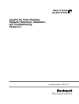
PAGE 15
22 SEPTEMBER 1998
Figure 3.2- GV3000 Drive (1-5 HP)
CH. 3: INSTALLATION
CH. 3: INSTALLATION
22 SEPTEMBER 1998
PAGE 16
R E G U L AT O R B O A R D
9.5
9
8.5
8
7.5
7
1.5
1
.5
10
.5
"Y "
1
"X"
1.5
2
2.5
85
10
15
90
95
3
56919-100B
CO N10 1
5
100
25
5
"Y"
"X"
TB 1
A IR
FLO W
AIR
FL O W
C O N2
CO N7
AU TO
F orw ard
ENTER
RUN NING M A N
R everse
RE M O T E
JOG
R UN
P R O G RA M
AU TO
JO G
FO R WA RD
RE V E R SE
PR O G R AM
20
S TA R T
RP M
VO LTS
A M PS
Hz
Kw
TO R Q U E
Pa ss w o rd
S TO P
RES ET
16
1
10
0-5 6930-100A
D A U G H TE R B O A R D
NETW O R K BO ARD
8 0 5 5 3 4 -B
8 0 5 5 3 4- A
Figure 3.3 - GV3000 Drive (7.5-10 HP)
PAGE 17
22 SEPTEMBER 1998
Figure 3.4 - GV3000 Drive (15-25 HP)
CH. 3: INSTALLATION
CH. 3: INSTALLATION
3.3
22 SEPTEMBER 1998
PAGE 18
Connecting the GV3000 Controller to a DeviceNet Network
When connecting to the DeviceNet network, the GV3000 controller should be wired with the same
cabling and termination as any other DeviceNet device. Refer to Volume 1 of the DeviceNet
Specification, Chapter 9.
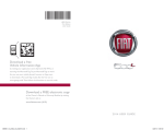
Table 3.1 - DeviceNet Wiring Pin-out
Terminal
Signal
Description
1
VPower 2
CAN_L
Signal 3
Drain
Shield
4
CAN_H
Signal +
5
V+
Power +
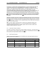
Figure 3.5 – 5-pin connector
(DeviceNet wiring)
Note: When connecting to the GV3000 drive (5-pin connector), use Table 3.1 to multi-drop
between drives.
PAGE 19
22 SEPTEMBER 1998
NOTES
CH. 3: INSTALLATION
CH. 4: SETUP
22 SEPTEMBER 1998
PAGE 20
CHAPTER 4: SETUP
4.1
General
This section describes how to configure the GV3000 controller (containing the DeviceNet
Network Communication Option Board) for use on the DeviceNet network. Refer to the GV3000
Installation and Operation Instruction Manual (D2-3287) for more information on the drive
parameters (P.xxx) described in Section 4.2. During setup, it is assumed that the network option
board is currently installed in the GV3000 as described in Chapter Three.
4.2
Network Communication Parameters
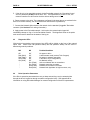
The drive becomes active on the DeviceNet network after the following steps are performed.
The steps need to be followed in the order listed to prevent drive fault(s).
1. Apply power to the drive.
2. Using the keypad on the drive, access the "Network Drop Number" parameter (P.060) and
assign a valid DeviceNet network address to the drive (only addresses 1 through 55 are
available).
3. Refering to the GV3000/SE AC General Purpose (Volts/Hertz) and Vector Duty Drive
Software Start-Up and Reference Manual:
a. Determine and set the "Network Connection Type" parameter (P.061)
Note: Because the Poll Connection (I/O) and the EDS Mapping (configuration) limits access to
the first 64 drive registers, the Network Connection Type parameter should remain 0-Basic for
most applications.
b. Determine and set the “Communications Loss Response” parameter (P.062)
Note: The DV3000 Option card behaves the same as the AutoMax Network Communications
Option Board with respect to loss of communications. Please note the warnings and precautions
described in the GV3000 Installation and Operation Instruction Manual (D2-3287). For
safety reasons, some modes require a hard-wired stop-switch.
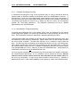
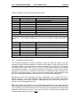
4. Set the "DeviceNet Baud Rate" parameter (P.063) to the desired value described in Table
4.1. Note that this parameter sets both the network baud rate and the size of the data packets
(and the drive parameters accessed) passed on the Poll connection. For more information on
control and control+config packets see Section: 5.2.
Value
0
1
2
3
4
5
6
Table 4.1 – Values for DeviceNet Baud Rate
Description
No network communications (Disables DeviceNet access)
125K baud, control only (Poll connection data width, See section 5.2.2)
250K baud, control only
500K baud, control only
125K baud, control+config
250K baud, control+config
500K baud, control+config
PAGE 21
22 SEPTEMBER 1998
CH. 4: SETUP
5. If the drive is to be controlled remotely via the DeviceNet network, the "Operation Control
Source" parameter (P.000) must be set to "OP". If this parameter is not set to "OP", the
network controller can still monitor the drive without taking control of it.
6. Remove power to the drive. The parameters configured in the steps above are retained in the
drive's non-volatile memory, but do not take effect until the drive is powered up.
7. Connect the Network Option board to the network via the standard "pluggable" DeviceNet
connector (See Section 3.3 for wiring information).
8. Apply power to the DeviceNet network. At this point, the network option board will
immediately attempt to "log on" to the DeviceNet network. The diagnostic LEDs on the option
card can be used to determine the status of the log-on.
4.3
Diagnostic LEDs
With the drive’s protective cover removed, two LEDs will be visible on the front of the network
option card. These LEDs: MS (Module Status) and NS (Network Status) can be useful in
determining network problems.
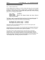
4.4
MS
NS
Problem/Condition
Off
Red (Solid)
Red (Flash)
Grn (Flash)
Grn (Solid)
‘’
‘’
‘’
‘’
Off
Off
Off
Off
Off
Grn (Flash)
Grn (Solid)
Red (Flash)
Red (Solid)
No power to drive
Load firmware mode (contact Tech. Support)
No power to network connection
P.063 set to 0 (no configuration)
No Network activity
Active on Network but no connections
Network connection to master
Network lost connection to master
Network fault (duplicate id, high bus errors, etc.)
Drive Operation Parameters
If the Drive’s operation parameters have not yet been entered, they may be entered either
through the drive’s keypad or through a network configuration utility. See Appendix B for
information on using DeviceNet Manager for network configuration of the drive’s parameters.
CH. 5: NETWORK PROGRAM
22 SEPTEMBER 1998
PAGE 22
CHAPTER 5: NETWORK PROGRAMMING
5.1
Drive Data Registers Overview
5.1.1
General
The drive is monitored and controlled over the network by reading and writing network
commands (Explicit, Poll or Bit-Strobed) to the drive’s data registers. The data registers are
addressed over the network by a register number (Reg #) and contain 16 bit values. The data
registers are divided into separate types according to function. Generally speaking, the
Tune/Config registers hold an image of the P.xxx and U.xxx parameters accessable by the
drive’s keypad and the Control/Reference registers hold an image of the drives physical inputs
(start, stop, speed ref., etc). When the drive is configured for network control and other certain
conditions are met, the drive registers accessed by the network option card are selected as an
alternate source for controlling the drive as opposed to the keypad and/or physical input.
Network data written to the drive’s data registers is buffered before it is transferred to the drive’s
internal regulator. In order to minimize regulator board CPU loading, the rate of transfer of
register data to the drive regulator varies for different data register types. Additionally, some
register data transfer are blocked until additional conditions are met. The sections that follow
describe each data type for input and output register data along with the drive’s response and
conditions for acceptance of transfer. The presented response times do not include DeviceNet
transfer times.
The drive data registers which may be read or modified are listed in a table in Horner Electric’s
Supplement (SUP-0096). The table lists the register number, type, access and description for
each register.
5.1.2
Input Data Update Response
The drive’s input data is categorized as one of three types: control/reference, tunable or
configurable. Control/reference inputs include data which require fast update rates. This
includes data such as sequencing inputs (start, stop, run/jog, fwd/rev, etc.) and speed/torque
reference. Control/reference inputs are transferred from the data registers to the regulator every
speed loop scan period (for the GV3000, every 5 milliseconds), or as often as it is required by
the drive. For example, if the drive is configured to obtain its torque reference from the option
port, it reads this data from the option port every torque loop control scan.
Tunable inputs include parameters which typically require modification or adjustment while the
drive is running. Tunable data includes parameters such as accel/decel rates, min/max limits,
gains or offsets, etc. Tunable inputs are transferred from the data register to the regulator
whenever the regulator performs the processing of new tunable parameters. This occurs
approximately every 100 milliseconds while the drive is running or stopped.
Configurable inputs include parameters, which alter the way that the drive operates in such a
way that they cannot be modified while the drive is running. Configuration data includes
parameters such as reference source selection, I/O configuration, motor/tach nameplate data,
etc. Configurable inputs are transferred from the data registers to the regulator whenever the
regulator performs processing of new configuration parameters. This occurs approximately
every 100 milliseconds while the drive is stopped. Values sent from the network master while
the drive is running are not read in and used by the drive regulator until the drive is stopped.
PAGE 23
5.1.3
22 SEPTEMBER 1998
CH. 5: NETWORK PROGRAM
Output Data Update Response
The drive output data is categorized as one of two types: runtime signal data or tunable
configuration and status data. Runtime signal data includes things such as selected speed
reference value, sequencing status (ready, running, etc.), drive fault flags, terminal block digital
inputs state, and front-panel display mode values (RPM, Volts, Amps). The information is
transferred from the regulator to the data registers every speed loop scan period (for the
GV3000, every 5 milliseconds).
Tunable configuration and status data includes all other information provided by the drive which
is not defined as runtime signal data. This would typically include all drive parameter values.
When accessed via the DeviceNet explicit connection, the data provides a complete image of
how the drive is configured and operating. Tunable configuration and status data are transferred
from the regulator to the data registers whenever the regulator performs the processing of new
tunable and configurable input parameters. This occurs every 100 milliseconds.
5.1.4
Limitation on Data Registers Accessible (Basic/Extended)
The data registers are divided into a Basic and Extended set. The Basic set covers the first 64
data registers while the Extended set includes the Basic set plus all remaining data registers.
Drive parameter “Network Connection Type” (P.061) selects the set and determines which data
registers will be updated or read by the regulator. While configured to the Basic set, the drive
will block transfer (reading and writing) to data registers above Register number 64.
Normally, networks are not used to access to data registers above register number 64.
Therefore, this option is especially useful in limiting the number of Tune/Config parameters
which are modifed in the regulator when using the Tune/Config option described below. Since
the network option board does not provide default values for those Tune/Config data registers
over register number 64, each Tune/Config data register above that number must be initialized
over the network when using the Extended set and the Tune/Config option.
Note: Use care not to inadvertently set Reg. 61 since this register (P.061) enables the Extended
set.
5.1.5
Input Data Transfer Conditions
The network option board must be actively communicating with a master (Poll connection
active), and it must be selected as the drive’s control source (P.000 = OP(2)) in order for any
inputs to be transferred from the data registers to the drive regulator. Note that the keypad
can still be used to change parameter values when the drive control source is the network option.
However, any changes made via the keypad are overwritten with data register values when the
next input data update occurs. This needs to be kept in mind if parameter changes need to be
made while the network option is the control source for the drive.
In addition, a network-controlled “Tune/Cnfg input enable” bit (Drive Control Word: Reg 32, bit
14) is provided to enable the transfer of tunable and configurable register data to the drive
regulator. Until this bit is set ON (1), only Control/Reference data registers are read in by
the drive regulator. This gives the master's application program direct control over when
tunable and configurable parameter values are read in by the drive, if at all.
CH. 5: NETWORK PROGRAM
22 SEPTEMBER 1998
PAGE 24
For example, if a master loads Tune/Config parameters, it must first initialize the tunable and
configurable parameter data through Explicit network messages to the appropriate data
registers. Then, a Poll network message setting the “Tune/Cnfg input enable” bit in the Drive
Control Word enables the transfer of this data to the drive’s data registers. Once the
Tune/Config register data is transferred to the drive’s regulator, the “Tune/Cnfg input enable” bit
must be reset to prevent regulator overhead and un-expected changes in Tune/Config
parameters. The “Tune/Config Update synchronization flag” described in Section 5.1.8 can be
used to determine when the regulator has transfered the data. Those Tune/Config data registers
not explicitly preloaded through Explicit network messages contain default values as described in
the Appendix C. Note that the default value is not the same as the value previously loaded by
the keypad.
Alternately, should the user prefer to leave the tune/config so that inputs are set exclusively by
the keypad and that the network only modifies the control/reference data to the drive, the master
should not set the “Tune/Cnfg input enable” bit during any network message writes to the Drive
Control Word (Reg 32). The drive is, then, configured locally, but start, stop, reset and reference
are sent from the network master.
Note: The user needs to exercise caution to prevent the unintentional setting of the
Tune/Cnfg input enable bit (Reg 32, bit 14). This could cause the drive to transfer uninitialized tune/config data from the network option card to the drive, which could
radically change the operation of the drive.
5.1.6
Output Data Transfer Conditions
All regulator output data is transferred to the data registers continuously. The network does not
have to be active, and the network option does not have to be selected as the drive control
source (P.000). No output enable control bit is necessary.
5.1.7
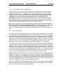
Data Transfer Summary
Table 5.1 summarizes the response times to the different drive data types described earlier in
this Sections 5.1.2, 5.1.3, and 5.1.6.
Table 5.1 – Transfer between Data Registers and the Drive Regulator
Direction
Category
Conditions
Rate
Input (to drive)
Control / Reference
drive running or stopped
5ms
Tunable
drive running or stopped
100ms
Output (from drive)
Configurable
Runtime
Tunable, Configuration &
Status
Drive stopped
Always
Always
100ms
5ms
100ms
PAGE 25
22 SEPTEMBER 1998
CH. 5: NETWORK PROGRAM
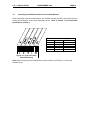
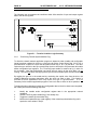
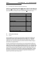
The following logic summarizes the conditions which effect transfer of input and output register
data to the drive’s regulator.
Figure 5.1 - Transfer Condition Logic Summary
5.1.8
Tune/Config Transfer Synchronization Flag
To allow the network master's application program to determine when tunable and configurable
inputs have been updated in the drive, a sync write bit (Drive Control Word: Reg. 32, bit 15) is
provided which is copied to a sync read bit (Status Word: Reg. 0, bit 7) by the drive. The drive
copies the sync write bit to the sync read bit after the drive has read in and processed all tunable
and/or configurable input registers. The “Tune/Cnfg input enable” bit must be set (1) in order for
this to happen. Note that configurable type inputs are only read in by the drive while it is not
running. This does not affect the copying of the sync bit since tunable inputs are still transferred.
By toggling the sync bit in the master and by monitoring the copied value from the drive, the
master's application program determines when the drive has read in data. This feature is
provided for those applications which may require this type of synchronization. It is not
necessary for the master's application program to use it as it has no affect on drive operation.
To determine when changes to tunable and configurable data on the drive have been completed,
the master performs the following sequence:
1.
2.
3.
4.
Modify the tunable and/or configurable register data in the appropriate network
register(s).
Set the Tune/Cnfg input enable flag (if not already set).
Toggle the network synchronization flag.
Monitor the loopbacked copy (read register) of the network synchronization flag until it
equals the value written in step 3.
CH. 5: NETWORK PROGRAM
5.1.9
22 SEPTEMBER 1998
PAGE 26
Parameter Processing Error Flag
A “Parameter Processing Error Flag” (Fault Log Entries: Reg. 14, bit 8) is provided to allow the
network master to determine whether any parameter values are unacceptable to the drive. If
this flag is set (1), then one or more data register values transfered to the drive were rejected. If
this flag is not set (0), then all data register values sent to the drive were accepted. Note that the
“tune/config inputs enable” bit must be set (1) before the drive can read-in, and consequently
process, any Tune/Config parameters. The parameter processing error flag is updated
approximately every 100 milliseconds.
5.1.10 Data Retention Timing Requirements
All tunable and configurable drive input register values must be maintained by the network
master's application program for at least 100 milliseconds to assure that they are seen by the
drive. This is particularly relevant for data which is transition-detected by the drive.
Control/reference data types generally do not have this 100 millisecond requirement since they
are scanned by the drive every 5 milliseconds. Special cases to this rule are the start input and
the error log clear command. The start input requires a 0 to 1 transition in order to start the
drive. The start input from the network may be delayed by the drive for up to 100 milliseconds.
This is done to synchronize a drive start to the processing of new configurable data. In order for
the network master to assure this 0 to 1 transition is detected by the drive, the network master
must maintain both the 0 and 1 states for at least 100 milliseconds each. Values which are
maintained for less time may not be detected by the drive.
The error log clear command bit is processed every 100 milliseconds even though it is defined in
the control/reference data section. A 0 to 1 transition must be detected by the drive after the
network is active and the control source has been selected to be the network option for
the error log to be cleared. In order for the network master to assure this 0 to 1 transition is
detected by the drive, it must maintain both the 0 and 1 states for a least 100 milliseconds each.
PAGE 27
22 SEPTEMBER 1998
CH. 5: NETWORK PROGRAM
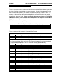
5.1.11 Inaccessible Drive Parameters (Keypad Only parameters)
There are a few GV3000 parameters which are not accessible through drive data registers, and
therefore, are not accessible through the DeviceNet network. Table 5.4 is a list of parameters
that are inaccessable. Because most of the inaccessable parameters are related to local drive
control functions only, the inability to access the parameters do not limit network control.
Table 5.2 – Inaccessable Parameters
Description
Parameter
Second menu enable password
P.006
Terminal block digital inputs config
P.007
Terminal block speed reference selection
P.008
Second accel rate
P.017
Second decel rate
P.018
MOP acc/dec rate
P.023
MOP reset configuration
P.024
Multispeed preset 1
P.031
Multispeed preset 2
P.032
Multispeed preset 3
P.033
Multispeed preset 4
P.034
Multispeed preset 5
P.035
Multispeed preset 6
P.036
Multispeed preset 7
P.037
Multispeed preset 8
P.038
Restore parameters defaults command
P.050
Program disable password
P.051
Network drop number
P.060
Vector torque loop self tune enable
U.008
5.2
Building Network Messages
5.2.1
General
Once a GV3000 drive with a network option card has been configured and is residing on an
active DeviceNet network, the drive data registers will be accessible over the network with
consideration to the above defined conditions (summarized in Section 5.1.7). These data
registers may then be read and/or written to the drive by a DeviceNet master (scanner) or
configuration utility. The following description provides the information necessary to program
such a master or configuration device.
A master or configuration device may use all three of the connections typically available on a
Group-2-Only-Server (Explicit, Poll and Bit-Strobed) to access register data. Accessing single
registers on a random basis is usually through the Explicit connection. The network option card
allows access to all the drive’s data registers through the Explicit connection. Accessing a group
of control data on a time-critical and periodic basis is usually through the Poll connection. The
network card limits the data registers accessable to two group of those typically used for realtime control. The order and size of these groups are fixed and cannot be modified. Providing
synchronization to other devices on the network is usually through the Bit-Strobe connection.
The network card allows this connection to alternately manipulate the Start/Stop bits in the
Sequence Control Word to start or stop the drive.
CH. 5: NETWORK PROGRAM
5.2.2
22 SEPTEMBER 1998
PAGE 28
Loss-of-Communications Considerations
When the drive’s “Control Source Select” (P.000) is set to OP (Option port), the drive will only
transfer input register data to the regulator when the network option card informs the regulator
that the network is “Active”. The network status is normally only considered “Active” if a Poll
connection has been established and is currently active. Therefore, a Poll connection must
established by the master before any input register data can be transfered to the
regulator. An exception is the use of DeviceNet Manager to modify the drive’s Tune/Config
data registers. Setting the “Tune/Cnfg inputs enable bit” (Reg.32, bit 14) through DeviceNet
Manager (which only uses the Explicit connection) will temporially assert “Network Active” until
the Tune/Config register data has been transferred to the drive’s regulator.
When a Poll connection is closed or disrupted, the drive will enter a state as defined by
the “Communications Loss Select” (P.062) parameter. If this parameter is set to 1-IET Fault,
the drive will fault. The Fault may be cleared over the network by re-establishing the Poll
connection and issuing the appropriate Reset command through the “Drive Control Word” (Reg.
32)
5.2.3
Poll Connection Data
The Poll connection provides the primary means of monitoring and controlling the drive. During
normal operation, the DeviceNet master will transfer a group of OUTPUT data in a Poll Request.
If the number of data registers (bytes) received matches the number expected by the network
option card, it will accept the OUTPUT data and reply with a Poll Response containing a group of
INPUT data. The number and specific data registers passed in a group is fixed; however, during
drive configuration one of two sets of groups may be selected for operation (P.063). These two
sets of groups are refered to as control only and control+config and are defined below.
Some applications will make use of a large number of drives with limited functionality connected
to a single network. Only certain parameters and diagnostic information commonly used will be
required for network control. Complete configuration over the network will not be a requirement
for these lowest cost, highest density, highest network performance applications. This type of
Poll connection will be referred to as the control only Poll connection. The network master will
issue a Poll request that contains 3 words of data for output to the drive, and the drive will return
a series of Poll response messages that contain 9 words of input data from the drive.
Other applications will accept a slower, lower density network in exchange for greater drive data
access over the network. This type of Poll connection is referred to as the control+config Poll
connection. When the drive is configured in this manner, the network master will issue a series
of Poll requests that contains 17 additional words of data and the drive will return a series of Poll
response messages that contains 6 additional words of data. Since a greater amount of network
data is transferred, the network scan rate performance is affected.
Neither the control or the control+config formats access any data registers beyond the Basic
set. If the Explicit connection is not used to access to access any data registers beyond Register
number 64, P.061 should be set to select the Basic set.
PAGE 29
22 SEPTEMBER 1998
CH. 5: NETWORK PROGRAM
Typically, the master must be programmed with the exact number of data registers to send and
receive. If the size of the data sent from the master does not match that expected by the slave,
the slave will neither accept the data or return a response. Likewise, if the data sent by slave
does not match that expected by the master, the master will probably generate an error. An
exception to this is the zero data length packet which has a special meaning to the network
option card. Some scanners will send zero length data packets to the slaves if they are placed in
a “standby” or “stop scan” mode. When the network option card receives a zero length Poll
or Bit-Strobe request, it will reset the Start and Stop bits in the Sequence Control Word
(Reg. 32, bits 0 and 1) to stop the drive.
Table 5.3 contains a summary of Poll packet sizes
Data Level
Control only
Control + config
Table 5.3 – Data Levels / Data to and from Drives
Data to Drive
Data from Drive
6 bytes
18 bytes
46 bytes
30 bytes
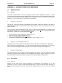
Table 5.4 shows the Poll Connection Command Data Format
Table 5.4 – Poll Connection Command Data
Word #
Drive Register #
Description
0
32
Drive Control Word
1
33
Network speed/torque reference
2
34
Network trim reference
(Poll connection consumption size = 6 bytes)
The following additional data is sent in the Poll command message if the drive is configured
to accept control+config data in the Poll command message (See Section 5.1).
Word #
Drive Register #
Description
3
37
Accel time
4
38
Decel time
5
39
Minimum speed
6
40
Maximum speed
7
41
Current limit percent
8
42
TS analog input offset
9
43
TS analog input gain
10
44
TS analog input configure
11
45
Trim gain
12
46
Draw gain
13
47
(Vector) Speed proportional gain
14
48
(Vector) Speed integral gain
15
49
Jog reference
16
51
Function loss response
17
52
RPM display scale
18
53
Control Booleans (see register table)
19
56
Output relay configuration
20
57
Trim ref source
21
58
Torque ref source / OCL feedback source
22
62
Option communications loss select
(Poll connection consumption size = 46 bytes)
CH. 5: NETWORK PROGRAM
22 SEPTEMBER 1998
PAGE 30
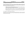
Table 5.5 shows the Poll Connection Reply Data Format
Table 5.5 – Poll Connection Reply Data
Drive Register #
Description
0
Status word (see register table)
1
Selected speed reference
2
Speed sum
3
(Vector) Speed feedback
4
TS analog input value
5
RPM display
6
Volts display
7
Amps display
8
Power display / Network output reg 1
(Poll connection production size = 18 bytes)
The following additional data will br returned in the Poll reply message if the drive is
configured to return control+config data in the Poll reply message message (See Section
5.1).
Word #
0
1
2
3
4
5
6
7
8
Word #
9
10
11
12
13
14
5.2.4
Drive Register #
12
13
14
Description
Fault latch bits, word 1
Fault latch bits, word 2
Number of error/faults, parameter processing error
flag
15
Error/fault log entries (n -1) and (n)
16
Active control source
27
Elapsed time meter readout
(Poll connection production size = 30 bytes)
Bit-Strobed Connection Data
The DeviceNet "Bit-strobed" connection provides a means by which the master device can
broadcast a single command message to all devices on the network. Each device receives the
message at exactly the same time with a control bit specifically for each device on the network.
The network option card makes use of it's "bit" in the bit strobe command to accomplish
synchronized drive startup. If a bit-strobe command is received, the network option card will
interrogate it's bit, and if set, will attempt to start the drive by setting both Start and !Stop bits in
the Drive Control Word Register. If the bit is not set, the network option card will attempt to stop
the drive by resetting both the Start and !Stop bits in the Drive Control Word Register.
Note that the drive’s other parameters must still be prepared for start operation with Poll or
Explicit messages. The zero data length Bit-strobe request will cause the network option card to
behave the same as if it received a reset bit. Additionally, the Poll connection must be active to
prevent a Loss of Communications Fault.
Note: The GV3000 only reads the run control word approximately every 100 milliseconds if the
Tune/config data is being written to the drive (20 mS otherwise), therefore, drive synchronization
can be skewed by up to 100 milliseconds. Also note that when the controller sends the bit-strobe
command to start the drive, the run control word in the Poll command must be updated (the
STOP bit deactivated), or the drive will not run.
PAGE 31
5.2.5
22 SEPTEMBER 1998
CH. 5: NETWORK PROGRAM
Explicit Connection Data
All drive registers with the exception of the Drive Control Word (Reg. 32) can be accessed
through the DeviceNet Explicit connection. A master scanner or configuration utility supporting
the Explicit connection will require a DeviceNet object “path” to each drive register which is to
be accessed. This path requires an object, instance and attribute number. Use the following
path format for accessing drive data registers:
Class number:
185 (0B9hex)
Instance number:
1
Attribute number:
Specific Drive Register Number (See Horner Electric’s
Supplement [SUP-0096].)
Technically, the option card supports the Explicit connection services "Get_attribute_single" and
"Set_attribute_single" to access a data register with the above provided path. Should the
master scanner or utility require a Service Code, provide the following:
Read Register (Get_attribute_single):
Write Register (Set_attribute_single):
10 (0Ahex)
16 (10hex)
Configuration utilities such as DeviceNet Manager may retrieve the data registers “path”
information from the provided EDS file.
As described above, the drive regulator will only transfer register input data when P.000 is set to
2 (Option card) and the Poll connection is active. However, it is valid to pre-load data registers
through the Explicit connection before a Poll connection is established.
An exception is when a master accesses the Drive Control Word with only the Explicit
connection active. If the “Tune/Cnfg input enable” bit is set, the network option board will
temporially inform the drive regulator to transfer the Tune/Config data registers. While this
exception is provided to allow operation with DeviceNet manager, it is not recommended for use
by a controlling scanner. Alternately, the scanner should enable this tranfer by setting the
“Tune/Cnfg input enable” bit through the active Poll connection.
APPENDIX A
22 SEPTEMBER 1998
PAGE 32
APPENDIX A: ACCESS TO DRIVE DATA REGISTERS
A1
DRIVE STATUS
A1.1.
General
The remote run-time status of the drive is typically returned in Drive Registers 0 through 11. These
values reflect the drives actual status regardless or the Control Source or the Auto/Remote mode. Refer
to Horner Electric’s Supplement (SUP-0096), Table1 (description column) to determine the Registers.
Registers 0, 1 and 5 are covered in more detail in this appendix.
a.
Register 0: Status Word
The first half of the word provides a bit-mapped run-time status of the drive similar to that which is
displayed by the keypad. The second half of the word provides an indication of the physical inputs to the
Control Terminal.
The "drive ready" status bit (Status Word: Reg. 0, bit 0) is used to indicate that a 0 to 1 transition on the
start input will start the drive. The drive ready status bit is ON (1) when all of the following conditions are
met and OFF (0) when one or more conditions are not met:.
•
•
•
•
No drive faults are active (Fault Active: Register 0, bit 2)
Stop input is ON (1) (!Stop: Register 32, bit 1)
Front-panel STOP/RESET button is not pressed
Function loss TB input closed (monitored w/Function Loss: Register 0, bit 12)
b.
Register 1: Selected Speed Reference
This register returns the currently selected speed reference. This value is scaled from 0 - 4095 where
4095 is the maximum allowable value. (i.e. The maximum 4095 value may correspond to 10 Volts at the
Control Terminal: Analog Speed Reference Input or the maximum value placed in Register 33).
c.
Register 5: RPM Display
This value returns the current output frequency (scaled) of the motor. The value returned is scaled
according to those formulas presented in the GV3000/SE AC General Purpose (Volts/Hz) and Vector
Duty Drive Software Startup and Reference Manual under Speed Display Scaling (P.028).
A1.2
Drive Control
A1.2.1 General
Network run-time drive control consists primarially of manipulating Drive Registers 32, 33, and
sometimes, 34. Once in OPtion mode, these parameters will be used to control the drive alternately to
those values input through the Control Terminal and/or Keypad when the drive is in LOCaL or rEmote
mode.
PAGE 33
22 SEPTEMBER 1998
APPENDIX A
A1.2.2 Register 32: Drive Control Word
The bits in this register are used by the drive alternately to the Discrete voltage inputs to the Control
Terminal. Generally, asserting a bit in the Drive Control Word while under OPtion mode performs the
same function as asserting a control voltage on the Control Terminal while under reMote mode.
Exception and specical conditions are listed as follows:
1. Before the drive can be started with the Start bit, the conditions which activate the Drive
Ready bit into the Status Word (Register 0) must be active.
2. Start bit must make a high to low transistion to start the drive. Once Drive Status indicates
the drive started, the Start bit can be reset. The drive is then stopped by releasing the Stop
bit .
3. Tune/Cnfg input enable bit will cause drive to accept option card default (or updated)
Tune/Config parameters. Setting this bit can severely alter drive operation (See Chapter 5).
A1.2.3 Register 33: Network Speed/torque Reference
This register is used to control the drive’s speed reference when the drive is in Option mode, and the
Remote/Local control is in Remote mode. This value is scaled such that the 0 is equal to stop and the
value 4095 is equal to full speed.
APPENDIX B
22 SEPTEMBER 1998
PAGE 34
APPENDIX B: CONFIGURING DRIVE WITH DEVICENET MANAGER
B1
DEVICENET MANAGER
B1.1
General
DeviceNet Manager is a popular software package distributed by Allen-Bradley, which provides an online method of programming Master and Slave DeviceNet devices. When DeviceNet Manager is loaded
with the provided EDS file, it may be used to program Tune/Config Drive Parameters (Registers) when
the Network Option card is on-line. However, only a majority of the first 64 drive registers are
accessable through DeviceNet Manager. Those first 64 parameters do include the drive Tune/Config
parameters which are most commonly accessed. Access to Tune/Config parameters above the first 64
will generally require an alternate method of configuration such as the drive’s keypad.
The lower 64 drive registers are divided into two sections. Within the first 32 registers are read-only
parameters which reflect the drive’s current values irregardless of which source is controlling the drive.
Within the second set of 32 registers, are the writeable registers which will be loaded to the drive
regulator under certain conditions. These conditions are covered in Chapter 5:
1.
2.
3.
Drive parameter (P.001) must be set to Option mode.
Drive must be stopped.
Tune/Cnfg input enable bit must be set (manually through DeviceNet Manager) to actually set
“Network Active” and copy upper 32 registers to drive.
Before DeviceNet Manager can be used to configure the drive, the provided EDS file must be installed.
Once installed, the DeviceNet Manager may be used add GV3000 drives to a Project and configure them
on-line. While examples are provided for the EDS installation and Device level configuration of the
GV3000, it is not within the scope of this document to provide complete instruction on the use of
DeviceNet Manager. Therefore, the user should be familiar with the DeviceNet Manager Software and
should give precedence to the DeviceNet Manager User Manual on any variations with those presented
here.
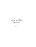
B1.2
Installation of EDS file
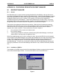
The installation of the EDS requires that the DeviceNet Manager Software must previously be installed.
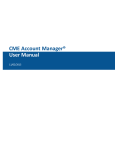
Run the DeviceNet Manager software. From the Utilities Menu, select "Install EDS Files...".
Figure 1
PAGE 35
22 SEPTEMBER 1998
APPENDIX B
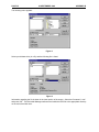
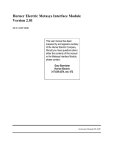
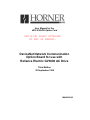
The following menu appears:
Figure 2
Select your diskette drive (A or B), and the following file is listed:
Figure 3
Information regarding the file is shown in the lower portion of the screen. Select the file named “1.eds”
and press “OK”. The DeviceNet Manager software now installs the EDS file to the appropriate directory
on the user’s hard disk drive.
APPENDIX B
B1.3
22 SEPTEMBER 1998
PAGE 36
Adding a GV3000 Device to a Project
Now that the EDS file is installed, the Reliance GV3000 Variable Frequency Drive is added to the list of
available DeviceNet products. Now a new or existing DeviceNet Project can be configured with the
Reliance GV3000 Variable Frequency Drive. To create or modify DeviceNet Projects and Networks,
refer to the DeviceNet Manager Software User Manual.
In the example below, a project named “Press_Rm” is open, and the Network named “Blanker” is
currently selected. The only device currently configured for that network is a SLC 500 DeviceNet
Scanner module.
Figure 4
To add a Reliance GV3000 Variable Frequency Drive to the network, press the “Add Device” button, and
a list of DeviceNet devices is displayed. Selecting either “All Product Types” or “Generic” displays a
group of devices, which include an entry for the Reliance GV3000 Variable Frequency Drive.
PAGE 37
22 SEPTEMBER 1998
APPENDIX B
Figure 5
The GV3000 may be added to the configuration by high-lighting that entry and supplying the other Node
information. For example, to add a GV3000 as Node 1, select the GV3000 item and change the Node
Address to 1. Optionally add an Name and Description, and press “OK.” The GV3000 is now added to
the list of devices on the BLANKER network as shown in Figure 6.
Figure 6
APPENDIX B
B1.4
22 SEPTEMBER 1998
PAGE 38
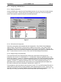
Configuring a GV3000 Device
B1.4.1 Display Configuration
Once the GV3000 entry is placed on the Project/Network screen, the user may zoom into that selection
to configure the module. Double-clicking on the GV3000 item brings up the “Device Configuration”
screen, which presents a detailed listing of the GV3000 parameters.
Figure 7
B1.4.2 Off-line/On-line Configuration
This device configuration screen displays two sets of information. If the “Status” field is displaying
“Default Values,” the information is coming from the EDS file and is off-line. If the “Status” field is
displaying “Device Values,” the information is coming from the actual on-line GV3000. Generally, the
configuration is done on-line unless the configuration is being saved to the project to be loaded at a later
date. To place the device on-line or off-line, refer to the DeviceNet Manager Users Manual.
B1.4.3 Display Groups (Current/Preload)
Those parameters which are displayed and/or modified are sub-divided into three groups: All
Parameters, and Current: T/C, and Preload: T/C. “All Parameters” displays a significant portion of the
first 64 drive registers. “Current: T/C” displays a significant portion of the Tune/Config parameters which
are currently being used by the drive (those T/C parameters which are read-only and are in the lower 32
registers). “Preload: T/C” displays a significant portion of the Tune/Config parameters (those T/C
parameters which are read/write and are in the second set of 32 parameters) which are loaded to the
drive when conditions are met as described in Sections B1.4.4 and B1.4.5.
The groupings are useful such that the user may select “Current: T/C” from the Parameter Group box to
display and record just the drives current parameter values (assuming device on-line). Then the user
may select “Preload: T/C” from the Parameter Group box to display just the current preload values. The
user may, then, modify and load the preload values as described in the following section.
PAGE 39
22 SEPTEMBER 1998
APPENDIX B
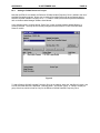
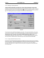
B1.4.4 Modifying a (Preload) parameter
Assuming that the configuration is currently on-line, from the Device Configuration screen, doubleclicking on a Parameter which needs modification to brings up detailed information. Note that the
Parameter number associated with the parameter does not match the drive register number. Therefore,
select the parameter by name. Also note that detailed screen will vary slightly according the parameter
type. The following screen shows the detailed screen for the Accel Rate parameter.
Figure 8
The parameter may be modified by changing the value field. This may be done directly or the mouse
may be used on the slide bar. Note that DeviceNet Manager may impose limitations on this field if the
parameter has a valid value range. The recommended default may also be selected by clicking the
“Select Default” button. Once the value is correct it must be loaded to the GV3000. This is
accomplished by clicking the “Save to Device” button. To verify the GV3000 received this value, the
user may click the “Load from Device” button and verify value is the same as that downloaded.
B1.4.5 Loading Preloaded Parameters to Drive
Once all the Tune/Config parameters (registers) are modified to the correct value, they may be loaded
into the drive memory. This requires that parameter P.000 be set to Option and that the drive is stopped.
Since the preloading through DeviceNet Manager only includes the first 64 drive data registers,
parameter P.061 must be set to 0 (Basic) to prevent the upper drive registers from being loaded with
non-initialized data.
APPENDIX B
22 SEPTEMBER 1998
PAGE 40
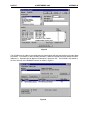
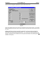
From the “Device Configuration” parameter list, select “Param Write Control”
Figure 9
Set the “Save Params to Drive” bit by clicking on it and then the “Save to Device” button. To verify that
the drive accepted the command, click on “Load from Device” and verify that the “Save Params to Drive”
bit is reset.
Additional verification that the drive recorded the parameters is to return to the “Drive Configuration Enhansed Mode” screen and select the group “Current: T/C”. Then click the “Read from Device” to
retreive the current parameters being used by the drive. The user may now verify the parameters were
changed. Note that due to drive limitations a few of the parameters settable in the preload group are not
readable in current group.
PAGE 41
22 SEPTEMBER 1998
APPENDIX C
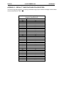
APPENDIX C: DEFAULT TUNE/CONFIGURATION REGISTERS
TheTune/Config data registers not explicitly preloaded through Explicit network messages contain default
values as described in Table 1.
Table 1- Default Tuning/Configuration
Register Preload Values
Register
Default Load Value
32
Stop
33
0
34
0
35
0
36
0
37
20.0
38
20.0
39
5.0
40
60.0
41
100
42
0
43
1.000
44
0
45
0
46
0
47
0
48
0
49
5.0
50
0
51
0
52
1800
53
0
54
0
55
0
56
0
57
0
58
0
59
0
60
0
61
0
62
0
63
P.063
MAN0096-03-A
07 MAY 1999
KEEP WITH USER MANUAL
07 May 1999
Revision pages for Horner Electric’s DeviceNet Network Communication
Option Board for use with Reliance Electric GV3000 AC Drive User Manual
HEC-GV3-DN, Third Edition
Attached to this cover page is a revision for the Horner Electric DeviceNet Network
Communication Option Board for use with Reliance Electric GV3000 AC
User Manual dated 22 September 1998 (MAN0096-03).
THESE REVISED REQUIREMENTS ARE NOW IN EFFECT.
New and revised pages may be issued periodically. For user manual updates, please contact
Horner Electric Advanced Products Group, Technical Support Division, at (317) 916-4274 or visit
our website at www.heapg.com.
Revision Key
Changes to text, tables or graphics contained in the attached
revision are indicated as follows:
1. Added text is underlined.
2. Deleted text is lined through.
3. New, revised, or deleted items are specified as such in ( ).
List of Effective Pages
The most current user manual consists of the following list of effective pages including
the attached revision pages: * Denotes new or revised pages
Page
Date
Front Cover…………….………….………….Contained in MAN0096-03 dated 22 September 1998
2 – 21.…………………………………………Contained in MAN0096-03 dated 22 September 1998
*22.………………..……….……………………………..………Revision Pages dated 07 May 1998
23-28.…………………………………..……..Contained in MAN0096-03 dated 22 September 1998
*29…………………..……………………………….…..……….Revision Pages dated 07 May 1999
30 -41………………………………………….Contained in MAN0096-03 dated 22 September 1998
CH.5: PROGRAMMING
07 MAY 1999
PAGE 22
CHAPTER 5: NETWORK PROGRAMMING
(NEW)
WARNING: Risk of severe bodily injury or equipment damage exists. The drive restarts if
the START and STOP bits in the control word are maintained high, and the PLC is switched from
Program to Run mode. Precautions need to be taken to ensure that these mode switches do
NOT create a hazard of bodily injury or equipment damage.
(Warning added 07 May 1999)
5.1
Drive Data Registers Overview
5.1.1
General
The drive is monitored and controlled over the network by reading and writing network commands
(Explicit, Poll or Bit-Strobed) to the drive’s data registers. The data registers are addressed over
the network by a register number (Reg #) and contain 16 bit values. The data registers are
divided into separate types according to function. Generally speaking, the Tune/Config registers
hold an image of the P.xxx and U.xxx parameters accessable by the drive’s keypad and the
Control/Reference registers hold an image of the drives physical inputs (start, stop, speed ref.,
etc). When the drive is configured for network control and other certain conditions are met, the
drive registers accessed by the network option card are selected as an alternate source for
controlling the drive as opposed to the keypad and/or physical input.
Network data written to the drive’s data registers is buffered before it is transferred to the drive’s
internal regulator. In order to minimize regulator board CPU loading, the rate of transfer of
register data to the drive regulator varies for different data register types. Additionally, some
register data transfer are blocked until additional conditions are met. The sections that follow
describe each data type for input and output register data along with the drive’s response and
conditions for acceptance of transfer. The presented response times do not include DeviceNet
transfer times.
The drive data registers which may be read or modified are listed in a table in Horner Electric’s
Supplement (SUP-0096). The table lists the register number, type, access and description for
each register.
5.1.2
Input Data Update Response
The drive’s input data is categorized as one of three types: control/reference, tunable or
configurable. Control/reference inputs include data which require fast update rates. This includes
data such as sequencing inputs (start, stop, run/jog, fwd/rev, etc.) and speed/torque reference.
Control/reference inputs are transferred from the data registers to the regulator every speed loop
scan period (for the GV3000, every 5 milliseconds), or as often as it is required by the drive. For
example, if the drive is configured to obtain its torque reference from the option port, it reads this
data from the option port every torque loop control scan.
Tunable inputs include parameters which typically require modification or adjustment while the
drive is running. Tunable data includes parameters such as accel/decel rates, min/max limits,
gains or offsets, etc. Tunable inputs are transferred from the data register to the regulator
whenever the regulator performs the processing of new tunable parameters. This occurs
approximately every 100 milliseconds while the drive is running or stopped.
Configurable inputs include parameters, which alter the way that the drive operates in such a way
that they cannot be modified while the drive is running. Configuration data includes parameters
such as reference source selection, I/O configuration, motor/tach nameplate data, etc.
Configurable inputs are transferred from the data registers to the regulator whenever the
regulator performs processing of new configuration parameters. This occurs approximately every
100 milliseconds while the drive is stopped. Values sent from the network master while the drive
is running are not read in and used by the drive regulator until the drive is stopped.
PAGE 29
07 MAY 1999
CH.5: PROGRAMMING
Typically, the master must be programmed with the exact number of data registers to send and
receive. If the size of the data sent from the master does not match that expected by the slave,
the slave will neither accept the data or return a response. Likewise, if the data sent by slave
does not match that expected by the master, the master will probably generate an error. An
exception to this is the zero data length packet which has a special meaning to the network option
card. Some scanners will send zero length data packets to the slaves if they are placed in a
“standby” or “stop scan” mode. When the network option card receives a zero length Poll or
Bit-Strobe request, it will reset the Start and Stop bits in the Sequence Control Word (Reg.
32, bits 0 and 1) to stop the drive.
(NEW)
WARNING: Risk of severe bodily injury or equipment damage exists. The drive restarts if
the START and STOP bits in the control word are maintained high, and the PLC is switched from
Program to Run mode. Precautions need to be taken to ensure that these mode switches do
NOT create a hazard of bodily injury or equipment damage.
(Warning added 07 May 1999)
Table 5.3 contains a summary of Poll packet sizes
Data Level
Control only
Control + config
Table 5.3 – Data Levels / Data to and from Drives
Data to Drive
Data from Drive
6 bytes
18 bytes
46 bytes
30 bytes
Table 5.4 shows the Poll Connection Command Data Format
Table 5.4 – Poll Connection Command Data
Word #
Drive Register #
Description
0
32
Drive Control Word
1
33
Network speed/torque reference
2
34
Network trim reference
(Poll connection consumption size = 6 bytes)
The following additional data is sent in the Poll command message if the drive is configured to accept
control+config data in the Poll command message (See Section 5.1).
Word #
Drive Register #
Description
3
37
Accel time
4
38
Decel time
5
39
Minimum speed
6
40
Maximum speed
7
41
Current limit percent
8
42
TS analog input offset
9
43
TS analog input gain
10
44
TS analog input configure
11
45
Trim gain
12
46
Draw gain
13
47
(Vector) Speed proportional gain
14
48
(Vector) Speed integral gain
15
49
Jog reference
16
51
Function loss response
17
52
RPM display scale
18
53
Control Booleans (see register table)
19
56
Output relay configuration
20
57
Trim ref source
21
58
Torque ref source / OCL feedback source
22
62
Option communications loss select
(Poll connection consumption size = 46 bytes)