1
Installer manual
NIBE™ F470
Exhaust air heat pump
LEK
IHB GB 1540-3
231494
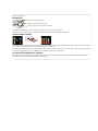
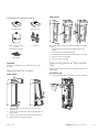
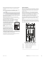
Quick guide
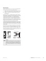
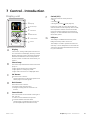
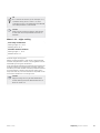
Navigation
Ok button (confirm/select)
Back button (back/undo/exit)
Control knob (move/increase/reduce)
A detailed explanation of the button functions can be found on page 31.
How to scroll through menus and make different settings is described on page 33.
Set the indoor climate
2X
The mode for setting the indoor temperature is accessed by pressing the OK button twice, when in the start mode
in the main menu. Read more about the settings on page 35.
To temporarily increase the amount of hot water, first turn the control knob to mark menu 2 (water droplet) and
then press the OK button twice. Read more about the settings on page 42.
In event of disturbances in comfort
If a disturbance in comfort of any type occurs there are some measures that can be taken before you need to
contact your installer. See page 58 for instructions.
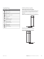
Table of Contents
1 Important information
Safety information
2 Delivery and handling
Transport
Assembly
Supplied components
Removing the covers
Removing parts of the insulation
2
Filling and venting
Start-up and inspection
26
27
8
7 Control - Introduction
31
2
8
8
9
9
9
3 The heat pump design
10
4 Pipe and ventilation connections
12
General pipe connections
Dimensions and pipe connections
Symbol key
Cold and hot water
Heating medium side
Supply air battery
Installation alternative
General ventilation connection
Ventilation flow
Adjusting ventilation
12
14
15
15
15
16
16
17
17
17
5 Electrical connections
18
General
Connections
Settings
Optional connections
Connecting accessories
18
20
22
22
25
6 Commissioning and adjusting
Preparations
NIBE™ F470
Display unit
Menu system
31
32
8 Control - Menus
35
Menu 1 - INDOOR CLIMATE
Menu 2 - HOT WATER
Menu 3 - INFO
Menu 4 - HEAT PUMP
Menu 5 - SERVICE
35
42
44
45
50
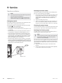
9 Service
54
Service actions
54
10 Disturbances in comfort
58
Info menu
Manage alarm
Troubleshooting
58
58
58
11 Accessories
60
12 Technical data
61
Dimensions and setting-out coordinates
Technical specifications
Energy labelling
Electrical circuit diagram
Index
61
62
64
66
72
26
26
Table of Contents |
1
1 Important information
Safety information
This manual describes installation and service procedures for implementation by specialists.
This appliance can be used by children
aged from 8 years and above and persons with reduced physical, sensory or
mental capabilities or lack of experience
and knowledge if they have been given
supervision or instruction concerning
use of the appliance in a safe way and
understand the hazards involved. Children shall not play with the appliance.
Cleaning and user maintenance shall
not be made by children without supervision.
The heat pump contains highly flammable refrigerant.
Special care should be exercised during handling, installation, service, cleaning and scrapping to avoid
damage to the refrigerant system and in doing so reduce the risk of leakage.
NOTE
Work on the refrigerant system must be done
by authorised personnel in accordance with
the relevant legislation on refrigerants, supplemented by additional requirements for flammable gas, for example, product knowledge
as well as service instruction on gas systems
with flammable gases.
Safety precautions
Wiring
Rights to make any design or technical
modifications are reserved.
Check that cabling will not be subject to wear, corrosion, excessive pressure, vibration, sharp edges or any
other adverse environmental effects. The check shall
also take into account the effects of aging or continual
vibration from sources such as compressors or fans.
©NIBE 2015.
Repairing sealed components
Symbols
NOTE
This symbol indicates danger to machine or
person.
Caution
This symbol indicates important information
about what you should observe when maintaining your installation.
TIP
This symbol indicates tips on how to facilitate
using the product.
Marking
F470 is CE marked and fulfils IP21.
The CE marking means that NIBE ensures that the
product meets all regulations that are placed on it
based on relevant EU directives. The CE mark is obligatory for most products sold in the EU, regardless where
they are made.
IP21 means that objects with a diameter larger than
or equivalent to 12.5 mm cannot penetrate and cause
damage and that the product is protected against
vertically falling drops of water.
2
Handling
Chapter 1 | Important information
When repairing sealed components, all electrical supply
must be disconnected from the equipment that is being
repaired before any sealed covers or similar are removed. If it is absolutely necessary to have an electricity
supply to the equipment during the service, continuously activated leak tracing must be performed at the
most critical points in order to warn of any dangerous
situations.
Pay particular attention to the following so that the
sheath is not changed in a way that affects the protection level when working with electrical components.
This means damage to cables, unnecessary amounts
of connections, terminals that do not follow the original
specifications, damaged gaskets, incorrect grommets
etc.
Ensure that the apparatus is secured properly.
Check that seals or sealing materials have not deteriorated to a degree that they can no longer prevent
combustible gases from entering. Replacement parts
must meet the manufacturer's specifications.
NOTE! Use of silicone seals can hamper the efficiency
of certain types of leak tracing equipment. Components
with built in safety do not need to be isolated before
starting work.
When working in the refrigerant circuit
Pipe installation should be kept to a minimum.
Connections in the refrigerant circuit must be carried
out as follows:
■ Soldered, welded or mechanical connections must
be made before the valves are opened to allow the
refrigerant to flow between the cooling system parts.
The system must be equipped with a vacuum valve
to relieve connecting pipes and/or any unfilled parts
of the cooling system.
NIBE™ F470
■ Reusable mechanical connectors and collared joints
are not permitted indoors.
■ Refrigerant pipes must be protected or recessed to
prevent damage.
■ Must be accessible for future maintenance.
National gas regulations must be observed.
Maximum amount of refrigerant: See Technical specifications.
■ Everyone who works with or opens a refrigerant circuit must have a current, valid certificate from an
accredited industry issuing body, which states that,
according to the industry's recognised assessment
standard, they have the authority to safely handle
refrigerants.
■ Servicing must only be performed according to the
equipment manufacturer's recommendations.
Maintenance and repairs that require the assistance
of another trained person must be carried out under
the supervision of person with the authority to handle
combustible refrigerants.
Maintenance and repair that requires the skill of another person must be carried out under the supervision of
someone with the above expertise.
Before work is started on systems that contains combustible refrigerants, safety checks must be performed
to ensure that the ignition risk is kept to a minimum.
The work must be carried out in a controlled way to
minimise the risk of contact with combustible gas or
liquid during the work.
All maintenance staff and those who work in close
proximity to the product must be instructed which type
of work is to be carried out. Avoid carrying out work
in enclosed spaces. The area surrounding the worksite
must be cordoned off. Ensure that the area is made
safe by removing combustible material.
Check whether there is refrigerant in the area using a
suitable refrigerant detector prior to and during work,
to notify the service technician whether there is a possible flammable atmosphere or not. Ensure that the
refrigerant detector is suitable for combustible refrigerant, i.e. does not generate sparks or cause ignition in
any other way.
If hot work is carried out on the heat pump, a powder
or carbon dioxide fire extinguisher must be to hand.
Those who carry out work with refrigerant system
connections, including exposing pipes that contain or
have contained combustible refrigerant, may not use
potential ignition sources in such a way that that can
lead to risks of fire or explosions.
All potential ignition sources, including cigarette
smoking, should be kept at a safe distance from the
service work area where combustible refrigerant can
leak out. Before carrying out work, the area surrounding the equipment must be checked to ensure that
there are no ignition risks. "No smoking" signs must be
displayed.
Ensure that the work is carried out outdoors or that
the work area is ventilated before the system is opened
and before any hot work is carried out. The area must
NIBE™ F470
be ventilated whilst the work is being carried out. There
must be ventilation around any refrigerant that comes
out, which should be routed outdoors.
If electrical components are replaced, the replacement
parts must be fit for purpose and have the correct
technical specifications. Always follow the manufacturer's guidelines regarding maintenance and servicing.
Contact the manufacturer's technical department in
the event of any doubts.
The following checks must be carried out for installations that use combustible refrigerants.
■ The filling quantity is appropriate for the size of the
space where the parts that contain refrigerant are
installed.
■ Ventilation equipment and outlet work correctly and
without obstructions.
■ If an indirect refrigerant circuit is used, check
whether the secondary circuit contains refrigerant.
■ All markings of equipment are visible and clear.
Markings, signs and similar that are not clear must
be replaced.
■ Refrigerant pipes and components are positioned in
such a way that it is not likely that they be subjected
to substances that can corrode components containing refrigerant, if these components are not made
of material that is resistant against corrosion, or not
appropriately protected against such corrosion.
Repair and maintenance of electrical components must
include initial safety checks and procedures for component inspection. In the event of a fault, which can
cause a safety risk, do not supply any power to the circuit until the fault has been rectified. If the fault cannot
be rectified immediately, and operation must continue,
an adequate temporary solution must be implemented.
This must be reported to the equipment owner, so that
all parties have been informed.
The following checks must be carried out at the initial
safety checks.
■ That the capacitors are discharged. Discharging must
be done safely, to prevent the risk of sparking.
■ That no powered electrical components or live cables
are exposed when filling or collecting refrigerant or
when the system is flushed.
■ That the system is continually grounded.
Removal and draining
When a cooling circuit is opened for repairs – or for
another reason– work must be carried out in a conventional manner. Due to the risk of fire it is important that
best practice is applied. Follow the procedure below.
1. Drain the refrigerant.
2. Flush the circuit with inert gas.
3. Drain the circuit.
4. Flush again with inert gas.
5. Open the circuit by cutting or burning.
Collect the refrigerant in the intended container. Flush
the system with oxygen-free nitrogen to make the
device safe. This process may need to be repeated
several times. Compressed air and oxygen may not be
used.
Chapter 1 | Important information
3
Flush the system by breaking the vacuum with oxygenfree nitrogen, and filling the system to working pressure, relieving the pressure to atmospheric pressure
and finally pumping to vacuum. Repeat the process
until no refrigerant remains in the system. After the final filling of oxygen-free nitrogen, relieve the pressure
in the system to atmospheric pressure, so that work
can be carried out. This type of flushing must be carried
out if hot work is to be performed on the pipe system.
of oil and refrigerant must be taken, if analyses are required before collected refrigerant can be reused. There
must be a power supply when this task is started.
1. Familiarise yourself with the equipment and its use.
2. Isolate the system electrically.
3. Before starting the procedure, ensure that:
Ensure that the vacuum pump's outlet is not near to
ignition sources and that there is satisfactory ventilation
by the outlet.
all necessary personal safety equipment is available
and used correctly
necessary equipment for mechanical handling of
the refrigerant container is available
the collection process is continuously supervised
by an authorised person
Filling
In addition to the conventional filling procedures, the
following actions must be taken.
■ Ensure that different refrigerants are not mixed when
filling equipment is used. Hoses and lines must be as
short as possible to minimise the enclosed refrigerant
volume.
■ Containers must be stored upright.
■ Ensure that the cooling system is grounded before
the system is filled with refrigerant.
■ Mark the system once filling is complete (if not
already marked).
■ Take extra care not to overfill the cooling system.
Before refilling the system, pressure test it with oxygenfree nitrogen. Leak test the system after filling but before using the system. Perform an additional leak test
before leaving the installation.
Leak testing
The following leak detection methods are deemed acceptable for systems containing flammable refrigerants.
Electronic leak detectors shall be used to detect flammable refrigerants, but the sensitivity may not be adequate, or may need re-calibration. (Detection equipment shall be calibrated in a refrigerant-free area.) Ensure that the detector is not a potential source of ignition and is suitable for the refrigerant used. Leak detection equipment shall be set at a percentage of the LFL
of the refrigerant and shall be calibrated to the refrigerant employed and the appropriate percentage of gas
(25 % maximum) is confirmed.
Leak detection fluids are suitable for use with most refrigerants but the use of detergents containing chlorine
shall be avoided as the chlorine may react with the refrigerant and corrode the copper pipe-work.
If a leak is suspected, all naked flames shall be removed/extinguished.
If a leakage of refrigerant is found which requires
brazing, all of the refrigerant shall be recovered from
the system, or isolated (by means of shut off valves) in
a part of the system remote from the leak. Oxygen free
nitrogen (OFN) shall then be purged through the system both before and during the brazing process.
Decommissioning
Before performing this procedure, the technician must
be familiar with the equipment and all its component
parts. Good practice prescribes that all refrigerant is
collected safely. Before the work is carried out, samples
4
Chapter 1 | Important information
4.
5.
6.
7.
8.
9.
10.
11.
the collection equipment and containers meet
appropriate standards.
Pump the refrigerant system to vacuum, if possible.
If it is not possible to pump to vacuum, manufacture a branch, so that the refrigerant can be retrieved from different parts of the system.
Check that the refrigerant container is on the scales
before starting to collect.
Start the collection device and collect according to
the manufacturer's instructions.
Do not overfill the containers (max. 80 % (volume)
liquid content).
Do not exceed the containers' maximum permitted
working pressure – not even temporarily.
When the containers have been filled correctly and
the process is complete, close all shut-off valves in
the equipment and remove and containers and
equipment from the installation immediately.
The collected refrigerant must not be filled in any
other system before being cleaned and checked.
Marking
The equipment must be marked stating that it has been
taken out of operation and drained of refrigerant. The
marking must be dated and signed. Check that the
equipment is marked indicating that it contains combustible refrigerant.
Collection
Best practice prescribes that all refrigerant is collected
safely when the refrigerant is drained from a system,
either for servicing or for decommissioning.
The refrigerant must only be collected in suitable refrigerant containers. Ensure that the required number of
containers, that can hold the entire volume of the system, are available. All containers that are to be used
must be intended for the collection of the refrigerant
and marked for this refrigerant (especially designed
for the collection of refrigerant). The containers must
have the correctly functioning relief valves and shutoff valves. Empty collection containers must be drained
and, if possible, chilled before collection.
The collection equipment must function correctly and
instructions for the equipment must be to hand. The
equipment must be suitable for the collection of combustible refrigerant.
Fully functioning and calibrated scales must also be to
hand.
NIBE™ F470
Hoses must be in good condition and be equipped with
leak proof quick-couplings. Before using the collecting
machine, check that it works correctly and has been
well maintained, and that corresponding electrical
components are sealed, to prevent ignition if any refrigerant should come out. Contact the manufacturer in
the event of any doubts.
Return the collected refrigerant to the refrigerant
supplier in the correct collection container and with
the relevant Waste Transfer Note. Do not mix refrigerants in collection devices or containers.
If compressors/compressor oil are/is to be removed
ensure that the affected device is drained to an acceptable level to ensure that no combustible refrigerant
remains in the lubricant. Compressors must be drained
before being returned to the supplier. Only electrical
heating of the compressor housing may be used to
quicken draining. Drain oil from the system in a safe
manner.
Serial number
Serial number
The serial number can be found at the bottom right of
the front cover and in the info menu (menu 3.1).
Installers are required to carry out the installation,
commissioning and servicing work in accordance with
the Benchmark Code of practice which is available from
the Heating and Hotwater Industry Council who manage and promote the Scheme. Visit www.centralheating.co.uk for information.
Warranty and insurance information
Thank you for installing a new NIBE heat pump in your
home.
NIBE heat pumps are manufactured in Sweden to the
very highest standard so we are pleased to offer our
customers a comprehensive guarantee.
The product is guaranteed for 24 months for parts and
labour from the date of installation or 33 months from
the date of manufacture, whichever is the shorter.
The NIBE guarantee is based on the unit being installed
and commissioned by a NIBE accredited installer, serviced every year and the Benchmark documents completed. Where this condition is not met, any chargeable
spare parts or components issued within the applicable
guarantee period still benefit from a 12 month warranty from the date of issue by the manufacturer.
We recommend the installer completes and returns as
soon as possible, your guarantee registration card or
completes the guarantee form on the NIBE website
www.nibe.co.uk.
Electrical Supply
The heat pump must be permanently connected to a
230V ac 50Hz supply.
Serial number
Caution
Always give the product's serial number (14
digits) when reporting a fault.
All system components shall be of an approved type
and all wiring to current I.E.E wiring regulations.
External wiring must be correctly earthed, polarised
and in accordance with the relevant standards: Currently this is BS 7671.
Domestic Hot Water
Country specific information
Great Britain
All domestic hot water circuits, connections and fittings
must be in accordance with the relevant standards and
water supply regulations. It should also be in accordance with the relevant requirements of the Local Authority and the Building Regulations relevant to the
location of installation.
This installation is subject to building regulation approval, notify the local Authority of intention to install.
BS 6700 Services supplying water for domestic use
within buildings and their cartilages.
Use only manufacturer’s recommended replacement
parts.
Water Supply (Water Fitting) Regulations 1999 or The
Water Bylaws 2000 (Scotland).
Installer manual
This installer manual must be left with the customer.
Heating System
The installation of the heat pump should follow best
practice as covered in the following:
Benchmark places responsibilities on both manufacturers and installers. The purpose is to ensure that customers are provided with the correct equipment for their
needs, that it is installed, commissioned and serviced
in accordance with the manufacturers instructions by
competent persons and that it meets the requirements
of the appropriate Building Regulations. The Benchmark Checklist can be used to demonstrate compliance
with Building Regulations and should be provided to
the customer for future reference.
NIBE™ F470
BS 5449 Forced circulation hot water central heating
systems for domestic premises.
BS 15450 Heating systems in buildings – Design of heat
pump heating systems.
Ventilation System
Any ventilation system should be designed and installed in accordance with Building Regulations, England & Wales Approved Document F1 and Scotland
Chapter 1 | Important information
5
Technical Standard Section 3.14 Ventilation. Only this
will ensure hygienic room air and prevent any dampness to the building structure.
To be able to ensure a high degree of efficiency and
an extremely comfortable living environment, we recommend that the installation of any ventilation system
should be planned and this plan be strictly followed
by the ventilation engineer.
We recommend that the exhaust and supply air is extracted and supplied via metal spiral seam pipes with
fitting seals approved to sealing class D, or suitable
equivalent UPVC plastic duct work and sealed with acrylic duct sealant. The exhaust air is extracted from the
bathroom, toilet, kitchen and utility room. This will also
apply to duct work carrying fresh air from the outside
that is preheated in the heat pump and supplied the
living quarters. Factors such as street noise, exhaust
fumes, wind, general noise, cold and pollen can be
taken into account choosing the right outside air vent.
This ensures a controlled ventilation system with heat
recovery and offers a high degree of comfort.
The discharge air duct work to outside must be insulated to ensure condensation does not form in the duct
work.
6
Chapter 1 | Important information
NIBE™ F470
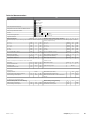
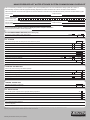
Inspection of the installation
Current regulations require the heating installation to be inspected before it is commissioned. The inspection must
be carried out by a suitably qualified person. Fill in the page for information about installation data in the User
manual.
✔
Description
Notes
Signature Date
Ventilation (page 17)
Setting ventilation flow exhaust air
Setting ventilation flow supply air
Connecting ground cables
Heating medium (page 15)
System flushed
System vented
Circulation pump setting
Setting heating medium flow
Boiler pressure
Setting trim valve, number of turns from
closed position
Expansion vessel
T&P valve
Tundish
Electricity (page 18)
Fuses heat pump
Fuses property
Outside sensor
Room sensor
Safety breaker
Earth circuit-breaker
Miscellaneous
Benchmark checklist
NIBE™ F470
Chapter 1 | Important information
7
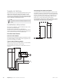
2 Delivery and handling
Transport
F470 should be transported and stored vertically in a
dry place. However. the F470 may be carefully laid on
its back when being moved into a building. The centre
of gravity is in the upper part.
heat pump and wall behind (and any routing of supply
cables and pipes), to reduce the risk of any transmission
of vibrations.
0
R
(50)
500
R
0
(80)
15 - 40 mm
Assembly
■ Position F470 on a firm base that can take the weight,
preferably on a concrete floor or foundation. Use the
product's adjustable feet to obtain a horizontal and
stable set-up.
NOTE
Ensure that there is sufficient space (300 mm)
above the heat pump for installing ventilation
hoses.
30 - 50 mm
■ The area where F470 is located must be equipped
with floor drainage.
■ Install with its back to an outside wall, ideally in a
30 - 50 mm
room where noise does not matter, in order to eliminate noise problems. If this is not possible, avoid
placing it against a wall behind a bedroom or other
room where noise may be a problem.
■ Wherever the unit is located, walls to sound sensitive
rooms should be fitted with sound insulation.
■ Route pipes so they are not fixed to an internal wall
that backs on to a bedroom or living room.
■ The heat pump's boiler room should always have a
temperature of at least 10 °C and max 30 °C.
Installation area
Leave a free space of 800 mm in front of the product.
Approx. 50 mm free space is required on each side, to
remove the side panels. The panels do not need to be
removed during service, all service on F470 can be
carried out from the front. Leave space between the
8
Chapter 2 | Delivery and handling
NIBE™ F470
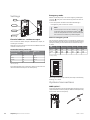
Side covers
Supplied components
Outside sensor
Room sensor
LEK
K
LEK
LEK
LE
K
LE
LE
K
Expansion vessel with
holder
(supplied separately)
The side covers can be removed to facilitate the installation.
1. Remove the screws from the upper and lower
edges.
2. Twist the cover slightly outward.
3. Move the hatch backwards and slightly to the side.
4. Pull the cover to one side.
5. Pull the hatch forwards.
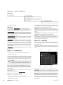
2 x tundish
Earth cable
Removing parts of the insulation
Location
The kit of supplied items is placed on top of the
product.
Parts of the insulation can be removed to facilitate the
installation.
Removing the covers
Insulation, top
Front cover
1. Grip the handle and pull straight out as illustrated.
1
3
4
2
LEK
LEK
LEK
1. Remove the air treatment hatch by pulling it
straight out.
2. Remove the screws from the lower edge of the
front cover.
3. Lift the cover out at the bottom edge and up.
4. Pull the hatch towards yourself.
NIBE™ F470
Chapter 2 | Delivery and handling
9
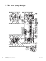
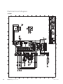
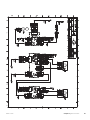
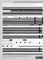
3 The heat pump design
EP13
BT22
XL33
BT21
HQ11
XL32
UR2
UR1
QM21
HQ10
BT20
UB1
LEK
EP1
UB2
XL31
AA4
FL5
AA101
XL34
GQ3
AA100
GQ2
SF1
AA4-XJ4
BT7
AA4-XJ3
HZ1
QN1
AA3
BT30
AA2
FD1
AA1
PF1
FA1
PF3
BT19
BT6
EB1
RF3
BT18
BT3
WP3
QM13 QN11
BT2
MA1
QM11
BP5
QM20
LEK / APH
GP1
LEK
WM2
CM1
RN1
WP1
QM31
FL2
FL6
XL3
BP2
WM1
XL2
QM32
XL8
XL1
XL4
WP2
BP1
CA1
AA102
GQ10
LEK
EB1
10
Chapter 3 | The heat pump design
GQ2
GQ10
XL32
XL31
UR1
NIBE™ F470
Pipe connections
XL 1
XL 2
XL 3
XL 4
XL 8
XL 29
XL 31
XL 32
XL 33
XL 34
Connection, heating medium flow line
Connection, heating medium return line
Connection, cold water
Connection, hot water
Connection, docking in
Connection, T&P valve
Ventilation connection, exhaust air
Ventilation connection, extract air
Ventilation connection, supply air
Ventilation connection, outdoor air
HVAC components
CM 1
EP 13
FL 1
FL 2
FL 5
FL 6
GP 1
QM 10
QM 11
QM 13
QM 20
QM 21
QM 31
QM 32
QN 11
QN 17
RN 1
WM 1
WM 2
WP 1
WP 2
WP 3
Expansion vessel
Supply air battery
Expansion relief valve, safety valve, hot water
heater
Safety valve, climate system
T&P valve
Vacuum valve
Circulation pump
Filler valve, hot water heater
Filler valve, climate system
Filler valve 2, climate system
Venting, heating medium
Venting, supply air coil1
Shut-off valve, heating medium flow
Shut off valve, heating medium return
Shunt valve
Pressure reduction valve with integrated check
valve
Trim valve
Tundish
Overflow water discharge
Overflow pipe, safety valve hot water heater
Overflow pipe, safety valve climate system
Overflow pipe, condensation
Sensors etc.
BP 1
BP 2
BP 5
BT 1
BT 2
BT 3
BT 6
BT 7
BT 16
BT 18
BT 19
BT 20
BT 21
High pressure pressostat
Low pressure pressostat
Pressure gauge, heating system
Outside sensor1
Temperature sensors, heating medium flow
Temperature sensors, heating medium return
Temperature sensor, hot water, control
Temperature sensor, hot water, display
Temperature sensor, evaporator1
Temperature sensor, compressor operation
Temperature sensor, immersion heater operation
Temperature sensor, exhaust air
Temperature sensor, extract air
NIBE™ F470
BT 22
BT 30
BT 50
Temperature sensor, supply air
Thermostat, backup heating
Room sensor1
Electrical components
AA 1
AA 2
AA 3
AA 4
Immersion heater card
Base card
Input circuit board
Display unit
AA4-XJ3 USB socket
AA4-XJ4 Service socket
AA100 Connection card air treatment section, exhaust
air
AA101 Connection card air treatment section, supply
air
AA102 Connection card compressor card
CA 1
Capacitor
EB 1
Immersion heater
FA 1
Miniature circuit-breaker
FA 2
Miniature circuit-breaker
FD 1
Temperature limiter
MA 1 Shunt motor with hand wheel
RF 3
EMC-filter
SF 1
Switch
W130 Network cable for NIBE UplinkTM
Cooling components
EP 1
GQ 10
HZ 1
QN 1
Evaporator
Compressor
Drying filter with tank1
Expansion valve1
Ventilation
GQ 2
GQ 3
HQ 10
HQ 11
UR 1
UR 2
Exhaust air fan
Supply air fan
Exhaust air filter1
Supply air filter1
Filter cover, exhaust air
Filter cover, supply air
Miscellaneous
PF 1
PF 3
UB1
UB2
1Not
Rating plate
Serial number plate
Cable gland
Cable gland
visible in the image
Designations in component locations according to
standard IEC 81346-1 and 81346-2.
Chapter 3 | The heat pump design
11
4 Pipe and ventilation connections
General pipe connections
Pipe installation must be carried out in accordance with
current norms and directives.
The system requires a low-temperature design of the
radiator circuit. At lowest dimensioned outdoor temperature (DOT) the highest recommended temperatures are 55 °C on the supply line and 45 °C on the return line.
cause damage. Likewise should the discharge pipes
(tundishes), drain valves and motorised valves be positioned clearly away from any electrical components.
This is the only thing the non-pressurised overflow pipe
may be used for. Even overflow pipes from tundish
connected to the expansion relief valve must be connected to the drain in the same way.
Please note that the connection of the T&P-valve should
not be used for any other purpose.
NOTE
Valves may not be positioned between the safety valve
and the water heater.
The pipe system needs to be flushed out before the heat pump is connected so that any
debris cannot damage component parts.
Overflow pipes from tundish must be routed with a
fall and at least 300 mm long, before bends or angles
in the pipework (see image).
NOTE
Metal discharge pipe from
temperature relief valve to tundish
This installation is subject to building regulation approval, notify the local Authority of intention to install.
Safety device
(e.g. temperature
relief valve)
600 mm maximum
Tundish
300 mm
minimum
NOTE
Use only manufacturer’s recommended replacement parts.
Fixed grating
Waste water from the collection tray at the evaporator
and from the safety valve is led by a non-pressurised
overflow pipe to the drain so that hot water cannot
Trapped gulley
Possible wall
Valve outlet size
Minimum size of dis- Minimum size of dis- Maximum resistance Resistance created by
charge pipe
charge pipe from
allowed, expressed
each elbow or bend
tundish
as a lenght of
straight pipe (i.e. no
elbows or bends)
G1/2
15 mm
22 mm
up to 9 m
0.8 mm
G1/2
15 mm
28 mm
up to 18 m
1.0 mm
G1/2
15 mm
35 mm
up to 27 m
1.4 mm
<G3>/4
22 mm
28 mm
up to 9 m
1.0 mm
<G3>/4
22 mm
35 mm
up to 18 m
1.4 mm
<G3>/4
22 mm
42 mm
up to 27 m
1.7 mm
G1
28 mm
35 mm
up to 9 m
1.4 mm
G1
28 mm
42 mm
up to 18 m
1.7 mm
G1
28 mm
54 mm
up to 27 m
2.3 mm
Hard water areas
Usually, there should not be a problem in installing
F470 in areas of hard water as the operating temperature is 50-60 °C.
12
Discharge below
fixed grating
Matal discharge pipe from tundish,
with continous fall.
Chapter 4 | Pipe and ventilation connections
Cleaning the climate system
When the water heater and the climate system have
been filled with water, F470 must operate at maximum
normal temperature for at least one hour. Thereafter
the system must be drained of water and refilled. See
section Service actions on page 54.
NIBE™ F470
Before installing the heat pump in an existing system,
it is important that the system is properly flushed
through.
Even if the heat pump is to be installed in a new system,
the heat pump and system should be flushed.
NOTE
Ensure that cleaning agent has been removed
from the entire system before adding inhibitor.
System diagram
F470 consists of a heat pump, water heater, immersion
heater, fans, circulation pump and control system.F470
is connected to the ventilation system and heating
medium circuit.
When the exhaust air at room temperature passes
through the evaporator, the refrigerant evaporates
because of its low boiling point. In this way the energy
in the room air is transferred to the refrigerant.
After flushing an inhibitor should be used for long-term
anti-corrosion protection.
The refrigerant is then compressed in a compressor,
causing the temperature to rise considerably.
NIBE Energy Systems Limited recommends water
treatments (supplied by e.g. Fernox and Sentinel) specifically designed for heat pumps.
The warm refrigerant is led to the condenser. Here the
refrigerant gives off its energy to the boiler water,
whereupon the refrigerant changes state from gas to
liquid.
Maximum boiler and radiator volumes
The refrigerant then goes via filters to the expansion
valve, where the pressure and temperature are reduced.
The volume of the pressure expansion vessel (CM1) is 10 litres and it
is pressurised as standard to 0.5
bar ((5 mvp). As a result, the maximum permitted height "H"
between the vessel and the
highest radiator is 5 metres; see
figure.
H
The refrigerant has now completed its circulation and
returns to the evaporator.
If the standard initial pressure in
the pressure vessel is not high
enough it can be increased by
adding air via the valve in the expansion vessel. The initial pressure
of the expansion vessel must be
stated in the inspection document. Any change in the
initial pressure affects the ability of the expansion vessel
to handle the expansion of the water.
The maximum system volume excluding the boiler is
219 litres at the above pre-pressure.
XL2
XL 1
XL 2
XL 3
XL 4
XL 8
NIBE™ F470
XL8
XL4
XL3
XL1
Connection, heating medium flow
Connection, heating medium return
Connection, cold water
Connection, hot water
Connection, docking
Chapter 4 | Pipe and ventilation connections
13
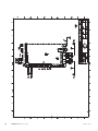
A
B
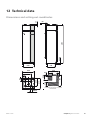
Dimensions and pipe connections
C
Setting out dimensions
Connection
XL1 Heating medium
supply
XL2 Heating medium return
XL3 Cold water
XL4 Hot water
XL8 Docking
WM1 Drip tray
A
B
C
(mm) 30
465
320
(mm) 45
420
365
(mm)
(mm)
(mm)
(mm)
455
400
290
200
210
260
295
420
80
170
175
60
Pipe dimensions
Connection
LEK
WM1
14
XL2
XL8
XL1
XL4
XL1-XL2 Heating medium ext Ø
XL3 Cold water ext Ø
XL4 Hot water ext Ø
XL8 Docking ext. Ø
WM2 Overflow water discharge
(mm)
(mm)
(mm)
(mm)
(mm)
22
22
22
22
32
XL3
Chapter 4 | Pipe and ventilation connections
NIBE™ F470
Symbol key
Symbol Meaning
Venting valve
Shut-off valve
Trim valve
Shunt / shuttle valve
Cold and hot water
Connecting cold and hot water
A mixer valve must also be installed if the factory setting for hot water is changed. National regulations
must be observed. The setting is made in menu 5.1.1
(page 50).
The flexible hose to the expansion vessel can be installed in the plugged connection on the safety valve.
Safety valve
Tundish
Temperature sensor
Expansion vessel
P
Pressure gauge
Circulation pump
Particle filter
Compressor
Heat exchanger
Heating medium side
Connecting the climate system
NIBE™ F470
Chapter 4 | Pipe and ventilation connections
15
Supply air battery
The supply air coil is connected in parallel with the radiator circuit and heats the house’s supply air. The
water flow through the supply air battery is set by
means of a trim valve (RN1). The supply air temperature
must be approximately the same as the indoor temperature, preferably a few degrees lower.
TIP
If possible, choose a cold day to adjust the trim
valve.
Connecting hot water circulation
To reduce the risk of bacterial growth in systems with
hot water circulation, the temperature of the circulating
water should not fall below 50 °C. There should not be
any non-circulatory hot water pipes. Adjust the hot
water system so that the temperature does not fall
below 50 ーC at the extremities of the system.
The circulation pump for hot water circulation can be
controlled by the heat pump. The HWC return can be
connected to a freestanding water heater.
Installation alternative
F470 can be installed in several different ways, some
of which are shown below.
Further option information is available at
www.nibe.co.uk and in the respective assembly instruction for the accessory used. See page 60 move the list
of the accessories that can be used to F470.
Extra hot water heaters
Extra hot water heaters
The heat pump should be supplemented with an electric water heater, if a hot tub or other significant consumer of hot water is installed.
Two or more climate systems
When more than one climate system is to be heated,
the following connection can be used.
The ECS 40/ECS 41 accessory is required for this connection.
16
Chapter 4 | Pipe and ventilation connections
NIBE™ F470
General ventilation connection
Ventilation flow
Ventilation installation must be carried out in accordance with current norms and directives.
Connect F470 so that all exhaust air except exhaust air
duct air (kitchen fan) passes the evaporator (EP1) in
the heat pump. The lowest ventilation flow must
comply with the applicable national standards. For
optimum heat pump operation the ventilation flow
must not fall below 28 l/s (100 m³/h) at an exhaust air
temperature of at least 20 °C. At times when the exhaust air temperature is below 20 °C (for example on
start up and when there is no one in the accommodation) the minimum value is 31 l/s (110 m³/h). The supply air flow must be lower than the exhaust air flow to
prevent over pressure in the house.
To prevent fan noise being transferred to the ventilation devices, it may be a good idea to install a silencer
in the duct. This is especially important if there are
ventilation devices in noise sensitive rooms.
Connections must be made via flexible hoses, which
must be installed so that they are easy to replace. The
extract air and outdoor air ducts are to be insulated
using diffusion-proof material along their entire
lengths. Ensure that the condensation insulation is
sealed at any joints and/or at lead-in nipples, silencers,
roof cowls or similar. Provision must be made for inspection and cleaning of the duct. Make sure that there are
no reductions of cross-sectional area in the form of
kinks, tight bends etc., since this will reduce the ventilation capacity. The air duct system must be a minimum
of air tightness class B. The extract air duct must be a
maximum of 20 m long with a maximum of six bends.
35
The heat pump’s installation area should be ventilated
60at least 5 l/s (18 m³/h). The installation area must
by
have a volume of at least 8 m³.
Ensure that the ventilation openings are not blocked.
Set the ventilation capacity in the heat pump's menu
system (menu 5.1.5).
Adjusting ventilation
Because the heat pump contains the flammable refrigerant propane (R290), the air ducting system must be
grounded. This is done by making a good electrical
connection to the ground cables enclosed (4 a) to the
four ventilation ducts. The cables must then be connected to the ground studs on top of the top cover.
2075
To obtain the necessary air exchange in every room of
the house, the exhaust air device and the supply air
device must be correctly positioned and adjusted and
the fans in the heat pump adjusted.
Immediately after installation adjust the ventilation so
that it is set according to the projected value of the
house.
Exhaust air duct /kitchen fan
Exhaust air duct (kitchen fan) must not be connected
to F470.
A defective ventilation installation may lead to reduced
installation efficiency and thus poorer operating economy, and may result in moisture damage to the house.
To prevent food vapour being transferred to F470 the
distance between the kitchen fan and the exhaust air
device must be considered. The distance should not be
less than 1.5 m.
25-50
Always use a kitchen fan when cooking.
NOTE
A duct in a masonry chimney stack must not
be used for extract air.
560
440
550
60
600
440
Ø125
NIBE™ F470
200
615
430
Extract air
195
Exhaust air
120
600
300
155
Supply air
Outdoor
air
200
Undvik rördragning
inom markerat område
Chapter 4 | Pipe and ventilation connections
17
5 Electrical connections
General
All electrical equipment, except the outdoor temperature sensors and room temperature sensors are ready
connected at the factory.
■ Disconnect the heat pump before any insulation test
of the house wiring is carried out.
■ If the building is equipped with an earth-fault
breaker, F470 should be equipped with a separate
one.
■ If a miniature circuit breaker is used it should have
at least motor characteristic “C”. See page 62 for
fuse size.
■ For the heat pump wiring diagram, see page 66.
■ Communication and sensor cables to external connections must not be laid close to high current cables.
■ The minimum area of communication and sensor
cables to external connections must be 0.5 mm² up
to 50 m, for example EKKX or LiYY or equivalent.
■ When cable routing in F470, cable grommets UB1and
UB2, (marked in image) must be used. In UB1 and
UB2 the cables are inserted through the heat pump
from the back to the front. For dimensions diagram
see page 20.
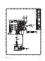
FD1
FD1-S2
FA1
Miniature circuit breaker (FA1)
Control (230 V), fans, compressor, circulation pump
etc. are internally fused by a miniature circuit breaker
(FA1).
Caution
Check the miniature circuit-breaker (FA1). It
may have tripped during transportation.
Temperature limiter (FD1)
UB1
UB2
The temperature limiter (FD1) cuts the current supply
to the electric additional heat if the temperature rises
between 90 and 100°C and can be manually reset.
Resetting
The temperature limiter (FD1) is accessible behind the
front cover. Reset the temperature limiter by carefully
pressing the button (FD1-SF2) using a small screwdriver.
NOTE
Temperature limiter, compressor (FD2)
The switch (SF1) must not be moved to " " or
" " until the boiler has been filled with water.
Otherwise the temperature limiter, thermostat
and the immersion heater can be damaged.
Temperature limiter (FD2) cuts the current supply to
the soft starter if the temperature rises above 88 °C
and is manually reset.
NOTE
Temperature limiter (FD2) is accessible behind the front
cover. The temperature limiter is reset by firmly pressing
in its button (FD2-SF2) using a small screwdriver.
LEK / APH
If the supply cable is damaged, only NIBE, its
service representative or similar authorised
person may replace it to prevent any danger
and damage.
Resetting
NOTE
Electrical installation and service must be carried out under the supervision of a qualified
electrician. Cut the current with the circuit
breaker before carrying out any servicing.
Electrical installation and wiring must be carried out in accordance with the stipulations in
force.
18
Chapter 5 | Electrical connections
NIBE™ F470
Accessibility, electrical connection
Removing the cover, base board
The plastic cap of the electrical boxes is opened using
a screwdriver.
Caution
To remove the cover for the base board, the
cover for the input circuit board must first be
removed.
NOTE
The cover for the input card is opened without
a tool.
Removing the cover, input circuit board
A
B
1
1
2
2
1. Insert the screwdriver (A) and pry the catch carefully downwards (B).
2. Angle out the cover and remove it.
1. Push the catch down.
2. Angle out the cover and remove it.
Cable lock
Use a suitable tool to release/lock cables in the heat
pump terminal blocks.
Removing the cover, immersion heater circuit
board
3
3
3
1
2
A
3
1
1
2
2
1
1
2
B
1
2
3
2
1
3
2
1
4
1
L
2
3
1
2
K
LE
4
EK
3
2
1. Insert the screwdriver (A) and pry the catch carefully downwards (B).
2. Angle out the cover and remove it.
NIBE™ F470
Chapter 5 | Electrical connections
19
Outside sensor
Connections
NOTE
To prevent interference, unscreened communication and/or sensor cables to external connections must not be laid closer than 20 cm
from high voltage cables.
Install the outdoor temperature sensor (BT1) in the
shade on a wall facing north or north-west, so it is unaffected by the morning sun for example.
Connect the sensor to terminal block X6:1 and X6:2 on
the input board (AA3). Use a twin core cable of at least
0.5 mm² cable area.
If a conduit is used it must be sealed to prevent condensation in the sensor capsule.
Power connection
F470 must be installed via an isolator switch with a
minimum breaking gap of 3mm. Minimum cable area
must be sized according to the fuse rating used. Supplied cable (length approx. 2 m) for incoming supply
electricity is connected to terminal block X1 on the
immersion heater board (AA1). The connection cable
can be found on the back of F470 (see dimensions
diagram below).
External
AA3-X6
BT1
1
2
3
4
5
6
7
8
AA3-X6
9
1670
UB1 and UB2
F470
300
Power supply cable
50
30
Connection 1x230V
AA1-X1
N
AA1-X1
PE
0
L1
1
PE1
Tariff control
If the voltage to the immersion heater and/or the
compressor disappears for a certain period, there must
also be blocking via the AUX-input at the same time,
see "Possible selection for AUX inputs".
20
Chapter 5 | Electrical connections
NIBE™ F470
Room sensor
F470 is supplied with a room sensor enclosed (BT50).
The room sensor has up to three functions:
1. Show current room temperature in F470's display.
2. Option of changing the room temperature in °C.
3. Makes it possible to change/stabilise the room
temperature.
Install the sensor in a neutral position where the set
temperature is required. A suitable location is on a free
inner wall in a hall approx. 1.5 m above the floor. It is
important that the sensor is not obstructed from
measuring the correct room temperature by being
located, for example, in a recess, between shelves, behind a curtain, above or close to a heat source, in a
draft from an external door or in direct sunlight. Closed
radiator thermostats can also cause problems.
The heat pump operates without the sensor, but if one
wishes to read off the accommodation's indoor temperature in F470's display, the sensor must be installed.
Connect the room sensor to X6:3 and X6:4 on the input
board (AA3).
If the sensor is to be used to change the room temperature in °C and/or to change/stabilise the room temperature, the sensor must be activated in menu 1.9.4.
If the room sensor is used in a room with under floor
heating it should only have an indicatory function, not
control of the room temperature.
RG 05
External
F470
F1245
1
2
3
4
5
6
7
8
9
AA3-X6
BT50
AA3-X6
Caution
Changes of temperature in accommodation
take time. For example, short time periods in
combination with underfloor heating will not
give a noticeable difference in room temperature.
NIBE™ F470
Chapter 5 | Electrical connections
21
Emergency mode
Settings
When the heat pump is set to emergency mode (SF1
is set to ), only the most necessary functions are activated.
■ The compressor and fans are off and heating is
managed by the immersion heater.
BT30
AA1-X3
NOTE
Switch (SF1) must not be moved to " " or " "
until F470 has been filled with water. Otherwise the temperature limiter, thermostat and
the immersion heater may be damaged.
AA1-SF2
AA1-X7
The immersion heater output is divided into steps, according to the table.
Setting maximum output in the electric additional heat
is done in menu 5.1.12.
Immersion heater power step
Electrical addition (kW)
Fusing (A)
Max (A)
0
2.67
5.30*
8
10
20
32
40
6.3
17.9
29.3
41
Power in emergency mode
The immersion heater power in emergency mode is set
with the dipswitch (S2) on the immersion heater board
(AA1) according to the table below. Default setting is
5.3 kW.
kW
1
2
3
4
5
6
2.67
5.30*
8
on
on
on
off
off
off
off
on
on
off
off
off
off
off
on
off
off
off
*Factory setting
*Factory setting
ON
The table displays the maximum phase current for the
relevant electrical step for the heat pump.
1 2 3 4 5 6
Electrical addition - maximum output
The image shows the dip-switch (AA1-S2) in the factory
setting, i.e. 5.3 kW.
Optional connections
NIBE Uplink™
Connect the network connected cable (straight, Cat.5e
UTP) with RJ45-contact (male) to RJ45 contact (female)
on the rear of the heat pump.
22
Chapter 5 | Electrical connections
NIBE™ F470
External connection options
F470 has software controlled inputs and outputs on
the input card (AA3), for connecting the external switch
function or sensor. This means that when an external
switch function or sensor is connected to one of six
special connections, the correct function must be selected to the correct connection in the software in F470.
The additional heat and/or the compressor are disconnected by connecting a potential-free switch function
to the input selected in menu 5.4, see page 52.
External blocking of addition and compressor can be
combined.
A closed contact results in the electrical output being
disconnected.
Caution
Contact for external tariff blocking
If an external switch function or sensor is connected to F470, the function to use input or
output must be selected in menu 5.4, see page
52.
In those cases where external tariff blocking is used, it
can be connected to terminal block X6 on the input
board (AA3), which is positioned behind the front
cover.
Selectable inputs on the input card for these functions
are AUX1 (X6:9-10), AUX2 (X6:11-12), AUX3 (X6:1314), AUX4 (X6:15-16) and AUX5 (X6:17-18). Selectable
outputs are AA3:X7.
Tariff blocking means that the additional heat, the
compressor, the heating and hot water are blocked by
connecting a potential-free switch function to the input
selected in menu 5.4, see page 52.
Closed switch means that tariff blocking is activated.
soft in/outputs5.4
NOTE
When tariff blocking is activated, the min.
supply line does not apply.
block heating
activate temp lux
not used
Switch for "SG ready"
not used
NOTE
not used
This function can only be used in mains networks that support the "SG Ready"-standard
.
alarm output
"SG Ready" requires two AUX inputs.
External
Externt
F470
F1245
B
A
AA3-X6
9
10
11
12
13
14
15
16
AA3-X6
The example above uses the inputs AUX1 (X6:9-10) andAUX2
(X6:11-12) on the input circuit board (AA3).
Caution
Some of the following functions can also be
activated and scheduled via menu settings.
In cases where this function is required it must be
connected to terminal block X6 on the input card (AA3).
"SG Ready" is a smart form of tariff control where your
electricity supplier can affect the indoor, hot water
and/or pool temperatures (if applicable) or simply block
the additional heat and/or compressor in the heat
pump at certain times of the day (can be selected in
menu 4.1.5 after the function is activated). Activate the
function by connecting potential-free switch functions
to two inputs selected in menu 5.4 (SG Ready A and
SG Ready B), see page 52.
Closed or open switch means one of the following:
■ Blocking (A: Closed, B: Open)
"SG Ready" is active. The compressor in the heat
pump and additional heat is blocked like the day's
tariff blocking.
Possible selection for AUX inputs
■ Normal mode (A: Open, B: Open)
Switch for external blocking of addition and/or
compressor
■ Low price mode (A: Open, B: Closed)
Blocking for addition heat and compressor is connected
on two different AUX inputs.
If external blocking of additional heat and/or compressor is wanted, this can be connected to terminal
block X6 on the input board (AA3), which is positioned
behind the front cover.
NIBE™ F470
"SG Ready" is not active. No effect on the system.
"SG Ready" is active. The system focuses on costs
savings and can for example exploit a low tariff from
the electricity supplier or over-capacity from any own
power source (effect on the system can be adjusted
in the menu 4.1.5).
■ Overcapacity mode (A: Closed, B: Closed)
Chapter 5 | Electrical connections
23
"SG Ready" is active. The system is permitted to run
at full capacity at over capacity (very low price) with
the electricity supplier (effect on the system is settable in menu 4.1.5).
(A = SG Ready A and B = SG Ready B )
Switch for +Adjust
Using +Adjust, the installation communicates with the
underfloor heating's control centre* and adjusts the
heat curve and calculated supply temperature according to the underfloor heating system's reconnection.
Activate the climate system you want +Adjust to affect
by highlighting the function and pressing the OK button.
*Support for +Adjust required
NOTE
+Adjust must first be selected in menu 5.4 ”soft
inputs/outputs”.
NOTE
Circuit board AA3 in the installation must have
at least ”input version” 34 and the software
version must have ”display version 5539 or
later for +Adjust to work. Version can be
checked in menu 3.1 under ”input version”
respectively ”display version”. New software
can be downloaded for free from
www.nibeuplink.com.
NOTE
In systems with both underfloor heating and
radiators, NIBE ECS 40/41 should be used for
optimum operation.
Switch for external blocking of heating
In those cases where external blocking of heat is used,
it can be connected to terminal block X6 on the input
board (AA3), which is positioned behind the front
cover.
Contact for activation of “temporary lux"
An external switch function can be connected to F470
for activation of the hot water function "temporary
lux". The switch must be potential-free and connected
to the selected input (menu 5.4, see page 52) on terminal block X6 on the input board (AA3).
"temporary lux" is activated for the time that the contact is connected.
Contact for activation of “external adjustment"
An external contact function can be connected to F470
to change the supply temperature and the room temperature.
When the switch is closed the temperature changes in
°C (if the room sensor is connected and activated). If a
room sensor is not connected or activated, the desired
change of "temperature" (heating curve offset) with
the number of steps selected is set. The value is adjustable between -10 and +10.
■ climate system 1
The switch must be potential-free and connected to
the selected input (menu 5.4, see page 52) on terminal block X6 on the input board (AA3).
The value for the change is set in menu 1.9.2, "external adjustment".
■ climate system 2 to 4
External adjustment for climate systems 2 to 4 requires accessory (ECS 40 or ECS 41).
See the accessory’s installer handbook for installation
instructions.
Contact for activation of fan speed
An external contact function can be connected to F470
for activation of one of the four fan speeds. The switch
must be potential free and connected to the selected
input (menu 5.4, see page 52) on terminal block X6 on
the input circuit board (AA3). When the switch closes,
the selected fan speed is activated. Normal speed is
resumed when the contact is opened again.
Heating operation is disconnected by connecting a
potential-free switch function to the input selected in
menu 5.4, see page 52.
A closed switch results in blocked heating operation.
NOTE
When heat blocking is activated, the min.
supply line does not apply.
Switch for external blocking of hot water
In cases where external blocking of hot water is used,
this can be connected to terminal block X6 on the input
board (AA3), which is positioned behind the front
cover.
Hot water operation is disconnected by connecting a
potential-free switch function to the input selected in
menu 5.4, see page 52.
A closed switch results in blocked hot water operation.
24
Chapter 5 | Electrical connections
NIBE™ F470
Possible selection for AUX output (potential
free variable relay)
1 2 3
It is possible to have an external connection through
the relay function via a potential free variable relay
(max 2 A) on the input circuit board (AA3), terminal
block X7.
Optional functions for external connection:
■ Indication of buzzer alarm.
■ Control of circulation pump for hot water circulation.
■ External circulation pump, for example external pump
and shunt group.
If any of the above is installed to terminal block X7 it
must be selected in menu 5.4, see page 52.
AA3-X7
C NO NC
F1X45
F470
Externt
External
L
N
PE
L
N PE
AA3-X7
Circulation pump
The common alarm is preselected at the factory.
NOTE
An accessory card is required if several functions are connected to terminal block X7 at
the same time that the buzzer alarm is activated (see page 60).
Connecting accessories
Instructions for connecting accessories are provided in
the manual accompanying the accessory. See page 60
for the list of the accessories that can be used with
F470.
1 2 3
C NO NC
AA3-X7
AA3-X7
The picture shows the relay in the alarm position.
When switch (SF1) is in the " " or “
relay is in the alarm position.
” position the
External circulation pump or hot water circulation
pump connected to the buzzer alarm relay as illustrated
below.
NOTE
Mark up any junction boxes with warnings for
external voltage.
NIBE™ F470
Chapter 5 | Electrical connections
25
6 Commissioning and adjusting
Venting the climate system
Preparations
1. Check that the switch (SF1) is in position " ".
2. Check that the filling valve (QM11) is fully closed.
Caution
Check the miniature circuit-breaker (FA1) in
the heat pump. It may have tripped during
transportation.
NOTE
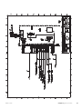
Filling and venting
QM13
FL2
1. Turn off the power supply to the heat pump.
2. Vent the heat pump via the vent valve (QM20) and
the rest of the climate system via the relevant vent
valves.
3. Vent the supply air battery via its vent valve
(QM21).
4. Keep topping up and venting until all air has been
removed and the pressure is correct.
FD1
QM21
SF1
The vent pipe from the container must be
drained of water before air can be released.
This means that the system is not necessarily
bled despite the flow of water when the bleed
valve (QM20) is opened.
LEK
BP5
QM20
LEK
WM1
QM32
FL1
QM31
Filling the hot water heater
1. Open a hot water tap in the house.
2. Open the externally mounted filler valve. This valve
should then be fully open during operations.
3. When water comes out of the hot water tap, the
hot water heater is full and the tap can be closed.
Filling the climate system
1. Check that the shut off valves for the heating system (QM31) and (QM32) are open.
2. Open the vent valves (QM20) and (QM21).
3. Check if the flexi hose supplied is connected
between connection (QM11) and connection
(QM13). Adjust the hose if this has not been done.
4. Open the filler valves (QM11), (QM13). The boiler
unit and the rest of the climate system are filled
with water.
5. When the water that exits the bleed valves (QM20)
and (QM21) is not mixed with air, close the valves.
After a while the pressure rises on the pressure
gauge (BP5). When the pressure reaches 2.5 bar
(0.25 MPa) the safety valve (FL2) starts to release
water. Close the filler valves (QM11) and (QM13).
6. Reduce the boiler pressure to the normal working
range (approx. 1 bar) by opening the vent valves.
(QM20) and (QM21) or the safety valve (FL2).
7. Check that there is water in the overflow cup
(WM1).
If the overflow cup requires topping up:
1. Turn the safety valve (FL1) anticlockwise carefully.
26
Chapter 6 | Commissioning and adjusting
NIBE™ F470
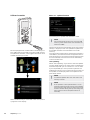
Start-up and inspection
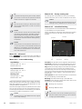
Start guide
Operation in the start guide
A. Page
B. Name and menu number
language 4.6
NOTE
There must be water in the climate system
before the switch is set to " ".
1. Set the heat pump's switch () to " ".
2. Follow the instructions in the start guide in the
heat pump display. If the start guide does not start
when you start the heat pump, start it manually in
menu 5.7.
TIP
See page 31 for a more in-depth introduction
to the heat pump’s control system (operation,
menus etc.).
If the start guide is left on this page it closes
automatically in
60 min
C. Option / setting
Commissioning
A. Page
The first time the heat pump is started a start guide is
started. The start guide instructions state what needs
to carried out at the first start together with a run
through of the heat pump’s basic settings.
Here you can see how far you have come in the start
guide.
The start guide ensures that the start-up is carried out
correctly and cannot be bypassed. The start guide can
be started later in menu 5.7.
F470
Scroll between the pages of the start guide as follows:
1. Turn the control knob until one of the arrows in
the top left corner (at the page number) has been
marked.
2. Press the OK button to skip between the pages in
the start guide.
Caution
B. Name and menu number
As long as the start guide is active, no function
in the installation will start automatically.
Read what menu in the control system this page of the
start guide is based on. The digits in brackets refer to
the menu number in the control system.
The guide will appear at each installation restart until it is deselected on the last page.
If you want to read more about affected menus either
read off in the sub-menu or in the installation manual
from page 35.
C. Option / setting
Make settings for the system here.
D. Help menu
In many menus there is a symbol that indicates
that extra help is available.
To access the help text:
1. Use the control knob to select the help symbol.
2. Press the OK button.
The help text often consists of several windows that
you can scroll between using the control knob.
NIBE™ F470
Chapter 6 | Commissioning and adjusting
27
Setting the ventilation
Power output
Effekt
(W)
(watt)
Ventilation must be set according to applicable standards. The supply air flow is adjusted so that it is 80%
of the exhaust air flow. The setting is made in menu
5.1.5.
Even if ventilation is roughly set at installation it is important that a ventilation adjustment is ordered and
permitted.
Power direct current fan exhaust air
140
90/100%
120
80%
100
70%
80
60
NOTE
40
Order a ventilation adjustment to complete
the setting.
20
60%
50%
40%
30%
0
0
10
20
30
40
50
60
70
80
90
Airflow
(l/s)
Luftflöde (l/s)
Availabletryck
pressure
Tillgängligt
(Pa)
(Pa)
Capacity direct current fan supply air
450
400
350
300
250
200
150
90/100%
100
50
30%
0
0
10
Power
Effekt
output
(watt)
(W)
20
40%
30
40
70%
60%
50%
80%
Airflow
50
60
Luftflöde
80 (l/s)
(l/s)
70
Power direct current fan supply air
120
90/100%
100
80%
80
70%
60
60%
40
50%
40%
20
30%
0
Airflow
0
10
Tillgängligt
Available pressure
tryck
(Pa)
(Pa)
20
30
40
50
60
70
80
Luftflöde
(l/s)
(l/s)
Capacity direct current fan supply air
450
400
350
300
250
90/100%
80%
200
150
70%
60%
100
50%
50
40%
30%
0
0
10
20
30
40
50
60
70
80
90
Airflow
(l/s)
Luftflöde (l/s)
28
Chapter 6 | Commissioning and adjusting
NIBE™ F470
according to the diagram below. The supply air temperature must be approximately the same as the indoor
temperature, preferably a few degrees lower.
Supply air battery
The water flow through the supply air coil is set by
means of a trim valve (RN1). This valve must be adjusted
to prevent unnecessary energy consumption in the
accommodation. The additional output is determined
TIP
Post-adjust the trim valve on a cold day.
VattenAvgiven
Water Rated
flöde
effekt
flow power
kW
kW
l/h
l/h
55/45
-35
-30
-25
-20
Trimventilinställning
(Antal
Trim
valveöppnade
setting varv)
(Number of opening turns)
DUT
DUT
-1
5
Fullt
Fully
öppen
open
400
7
Risk of low supply
air temperature
3
DUT
-35
-30
4
-25 35/25
300
-20
3
-15
2
200
2
1
100
1
Pressure drop
Tryckfall
radiator-/
värmesystem-/
coil circuit
batterikrets
mvp
mvp
5
Supply
air
Tilluftsflow
flöde
4
3
2
1
0
50
100
150
200
250
m³/h
m³/h
The delivered output in the diagram is calculated when dimensioning the heating system 55/45°C respective 35/25°C (underfloor
heating).
Example: If the supply flow is regulated to 150 m³/h
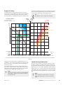
and DOT is -20 °C at a pump pressure (= pressure drop
coil circuit) of 3.3 mvp (33 kPa), gives the setting 2.8
on the trim valve.
This means that the trim valve must be opened 2.8
turns from closed position. At the same time it can be
read that the coil supplies the supply air with approximately 3 kW of additional output at -20 °C.
NOTE
Vent the coil using the venting screw (QM21)
repeatedly in order to ensure the circulation
through the coil.
NIBE™ F470
Commissioning without fans
The heat pump can be run without recovery, as only
an electric boiler, to produce heat and hot water, for
example before the ventilation installation is complete.
Enter menu 4.2 - "op. mode" and select "add. heat only"
Enter menu 5.1.5 - "fan sp. exhaust air" and reduce the
fan speed to 0%. Also go to menu 5.1.6 - "fan sp. supply
air" and reduce the fan speed on the supply air fan to
0%.
NOTE
Select operating mode "auto" or "manual"
when the heat pump is to run on recovery
again.
Chapter 6 | Commissioning and adjusting
29
Setting the pump speed
The speed of the circulation pump (GP1) is set using
the switch (GP1-SF4) on the pump so that it achieves
the projected flow for the house.
LE
K
LE
K
GP1-SF4
Tillgängligt
tryck
Pressure
(kPa)
Capacity circulation pump
(kPa)
60
50
40
30
III
20
II
10
I
0
0
0,05
0,11
0,16
0,22
0,27
0,33
0,38
Luftflöde
(l/s)
0,38
Flöde
(l/s)
Flow (l/s)
Output circulation pump
Effekt
Power
output
(W)
(watt)
50
III
45
40
35
30
II
25
20
15
10
I
5
0
0
0,05
0,11
0,16
0,22
0,27
0,33
Flow (l/s)
Post-adjustment, venting
Air is initially released from the hot water and venting
may be necessary. If gurgling sounds can be heard from
the heat pump or climate system, the entire system will
require additional venting. Vent the heat pump
through venting valve (QM20), and through the supply
air coil's venting valve(QM21). When venting, F470
must be off.
30
Chapter 6 | Commissioning and adjusting
NIBE™ F470
7 Control - Introduction
Display unit
INDOOR CLIMATE
HEAT PUMP
HOT WATER
INFO
F
A Display
D Back button
F470
A
Display
B
Status lamp
C
OK button
D
Back button
E
Control knob
Control knob
F
Switch
) (see page 54)
Emergency mode must only be used in the
event of a fault on the heat pump. In this mode,
the compressor and fans switch off and the
immersion heater engages. The heat pump
display is not illuminated and the status lamp
illuminates yellow.
OK button
E
The switch assumes three positions:
■ On ( )
■ Standby ( )
■ Emergency mode (
B Status lamp
C
Switch (SF1)
G
USB port
The USB port is hidden beneath the plastic
badge with the product name on it.
The USB port is used to update the software.
Visit http://www.nibeuplink.com and click the
"Software" tab to download the latest software
for your installation.
Instructions, settings and operational information are shown on the display. The easy-to-read
display and menu system, facilitates navigation
between the different menus and options to
set the comfort or obtain the information you
require.
The status lamp indicates the status of the heat
pump. It:
■ lights green during normal operation.
■ lights yellow in emergency mode.
■ lights red in the event of a deployed alarm.
The OK button is used to:
■ confirm selections of sub menus/options/set
values/page in the start guide.
The back button is used to:
■ go back to the previous menu.
■ change a setting that has not been confirmed.
The control knob can be turned to the right or
left. You can:
■ scroll in menus and between options.
■ increase and decrease the values.
■ change page in multiple page instructions
(for example help text and service info).
NIBE™ F470
Chapter 7 | Control - Introduction
31
Symbols in the display
Menu system
When the door to the heat pump is opened, the menu
system’s four main menus are shown in the display as
well as certain basic information.
Outdoor
temperature
Indoor temperature - (if room sensors are installed)
INDOOR CLIMATE
HOT WATER
The following symbols can appear in the display during
operation.
Symbol
Description
This symbol appears by the information
sign if there is information in menu 3.1
that you should note.
Hot water temp.
These two symbols indicate whether the
compressor or addition is blocked in
F470.
Information about
operation
SERVICE
HEAT PUMP
Temporary lux (if activated)
INFO
These can, for example, be blocked depending on which operating mode is selected in menu 4.2, if blocking is scheduled in menu 4.9.5 or if an alarm has occurred that blocks one of them.
Estimated amount of hot water
Blocking the compressor.
Blocking additional heat.
Menu 1 - INDOOR CLIMATE
Setting and scheduling the indoor climate. See page
35.
This symbol appears if periodic increase
or lux mode for the hot water is activated.
Menu 2 - HOT WATER
Setting and scheduling hot water production. See page
42.
This symbol indicates whether "holiday
setting" is active in 4.7.
Menu 3 - INFO
This symbol indicates whether F470 has
contact with NIBE Uplink™.
Display of temperature and other operating information and access to the alarm log. See page 44.
Menu 4 - HEAT PUMP
Setting time, date, language, display, operating mode
etc. See page 45.
Menu 5 - SERVICE
Advanced settings. These settings are not available to
the end user. The menu is made visible by pressing the
Back button for 7 seconds when in the start menu. See
page 50.
32
Chapter 7 | Control - Introduction
This symbol indicates the actual speed of
the fan if the speed has changed from
the normal setting.
This symbol indicates whether solar
heating is active.
Accessory needed.
NIBE™ F470
Menu number – marked sub menu
Name and menu number – main menu
Symbol – main
menu
INDOOR CLIMATE
HOT WATER
INDOOR CLIMATE 1
temperature
ventilation
normal
scheduling
off
advanced
HEAT PUMP
INFO
Marked main menu
Symbols – sub menus
Operation
To move the cursor, turn the control knob
to the left or the right. The marked position
is white and/or has a turned up tab.
Status information – sub menus
Name – sub menus
Setting a value
time & date4.4
time
24 h
Selecting menu
12 h
To advance in the menu system select a main menu by
marking it and then pressing the OK button. A new
window then opens with sub menus.
Select one of the sub menus by marking it and then
pressing the OK button.
date
day
month
year
Selecting options
comfort mode2.2
economy
normal
luxury
Alternative
In an options menu the current selected option is
indicated by a green tick.
Values to be changed
To set a value:
1. Mark the value you want to set using the
control knob.
2. Press the OK button. The background of the
value becomes green, which means that you
have accessed the setting mode.
3. Turn the control knob to the right to increase
the value and to the left to reduce the value.
4. Press the OK button to confirm the value you
have set. To change and return to the original
value, press the Back button.
To select another option:
1. Mark the applicable option. One of the options
is pre-selected (white).
2. Press the OK button to confirm the selected
option. The selected option has a green tick.
NIBE™ F470
Chapter 7 | Control - Introduction
33
Use the virtual keyboard
Help menu
In many menus there is a symbol that indicates
that extra help is available.
To access the help text:
1. Use the control knob to select the help symbol.
2. Press the OK button.
Different keyboards
The help text often consists of several windows that
you can scroll between using the control knob.
In some menus where text may require entering, a virtual keyboard is available.
Depending on the menu, you can gain access to different character sets which you can select using the control knob. To change character table, press the Back
button. If a menu only has one character set the keyboard is displayed directly.
When you have finished writing, mark "OK" and press
the OK button.
Scroll through the windows
A menu can consist of several windows. Turn the control knob to scroll between the windows.
Current menu
window
Number of windows
in the menu
Scroll through the windows in the start guide
language 4.6
Arrows to scroll through window in start guide
1. Turn the control knob until one of the arrows in
the top left corner (at the page number) has been
marked.
2. Press the OK button to skip between the steps in
the start guide.
If the start guide is left on this page it closes
automatically in
34
60 min
Chapter 7 | Control - Introduction
NIBE™ F470
8 Control - Menus
Menu 1 - INDOOR CLIMATE
Overview
1 - INDOOR CLIMATE
1.1 - temperature
1.2 - ventilation
1.3 - scheduling
1.3.1 - heating
1.3.3 - ventilation
1.9 - advanced
1.9.1.1 - heating curve
1.9.2 - external adjustment
1.9.3 - min. flow line temp.
1.9.4 - room sensor settings
1.9.6 - fan return time
1.9.7 - own curve
1.9.8 - point offset
1.9.9 - night cooling
For the menu INDOOR CLIMATE there are several submenus. Status information for the relevant menu can
be found on the display to the right of the menus.
To change the room temperature, use the control knob
to set the desired temperature in the display. Confirm
the new setting by pressing the OK button. The new
temperature is shown on the right-hand side of the
symbol in the display.
temperature Setting the temperature for the climate
system. The status information shows the set values
for the climate system.
Setting the temperature (without room sensors
activated):
Sub-menus
ventilation Setting the fan speed. The status information shows the selected setting.
scheduling Scheduling heating and ventilation. Status
information "set" is displayed if you set a schedule but
it is not active now, "holiday setting" is displayed if the
vacation schedule is active at the same time as the
schedule (the vacation function is prioritised), "active"
displays if any part of the schedule is active, otherwise
it displays "off".
advanced Setting of heat curve, adjusting with external contact, minimum value for supply temperature,
room sensor and night cooling.
Menu 1.1 - temperature
Set the temperature (with room sensors installed
and activated):
heating
Setting range: 5 – 30 °C
Default value: 20
The value in the display appears as a temperature in
°C if the climate system is controlled by a room sensor.
Caution
A slow heat-releasing heating system, such as
for example, underfloor heating, may not be
suitable for control using the heat pump's
room sensor.
NIBE™ F470
Setting range: -10 to +10
Default value: -1
The display shows the set values for heating (curve
offset). To increase or reduce the indoor temperature,
increase or reduce the value on the display.
Use the control knob to set a new value. Confirm the
new setting by pressing the OK button.
The number of steps the value has to be changed to
achieve a degree change of the indoor temperature
depends on the heating installation. One step is usually
enough but in some cases several steps may be required.
Setting the desired value. The new value is shown on
the right-hand side of the symbol in the display.
Caution
An increase in the room temperature can be
slowed by the thermostats for the radiators or
under floor heating. Therefore, open the
thermostats fully, except in those rooms where
a cooler temperature is required, e.g. bedrooms.
If the exhaust air temperature falls below 16
°C the compressor is blocked and electric additional heat is permitted. Heat is not recovered
from the exhaust air when the compressor is
blocked.
Chapter 8 | Control - Menus
35
TIP
Activated
Wait 24 hours before making a new setting,
so that the room temperature has time to
stabilise.
SCHEDULING HEATING
schedule 1
If it is cold outdoors and the room temperature
is too low, increase the curve slope in menu
1.9.1.1 by one increment.
activated
Setting range: normal and speed 1-4
Default value: normal
system
tues
we
thur
fri
21:30 - 06:00
20.5°
sat
sun
Conflict
Day
Time period
Adjusting
Schedule: The schedule to be changed is selected here.
Activated: Scheduling for the selected period is activated here. Set times are not affected at deactivation.
System: Which climate system the schedule is for is
selected here. This alternative is only displayed if more
than one climate system is present.
When you have selected a new speed a clock starts a
count down. When the time has counted down the
ventilation speed returns to the normal setting.
Day: Select which day or days of the week the schedule
is to apply to here. To remove the scheduling for a
particular day, the time for that day must be reset by
setting the start time to the same as the stop time. If
the line "all" is used, all days in the period are set for
these times.
If necessary, the different return times can be changed
in menu 1.9.6.
Time period: The start and stop time for the selected
day for scheduling are selected here.
The fan speed is shown in brackets (in percent) after
each speed alternative.
TIP
Adjusting: How much the heating curve is to be offset
in relation to menu 1.1 during scheduling is set here.
If the rooms sensor is installed the desired room temperature is set in °C.
If longer time changes are required use the
holiday function or scheduling.
Conflict: If two settings conflict with each other a red
exclamation mark is displayed.
The ventilation in the accommodation can be temporarily increased or reduced here.
Menu 1.3 - scheduling
TIP
In the menu scheduling indoor climate (heating/ventilation) is scheduled for each weekday.
If you wish to set similar scheduling for every
day of the week start by filling in “all” and then
changing the desired days.
You can also schedule a longer period during a selected
period (vacation) in menu 4.7.
TIP
Menu 1.3.1 - heating
Increases or decreases in the accommodation temperature can be scheduled here for up to three time periods per day. If a room sensor is installed and activated
the desired room temperature (°C) is set during the
time period. Without an activated room sensor the
desired change is set (of setting in menu 1.1). One step
is usually enough to change the room temperature by
one degree, but in some cases several steps may be
required.
36
1.3.1
schedule 3
mon
If it is warm outdoors and the room temperature is too low, increase the value in menu 1.1.1
by one increment.
Menu 1.2 - ventilation
schedule 2
System
all
If it is cold outdoors and the room temperature
is too high, reduce the curve slope in menu
1.9.1.1 by one increment.
If it is warm outdoors and the room temperature is too high, reduce the value in menu 1.1.1
by one increment.
Schedule
Chapter 8 | Control - Menus
Set the stop time earlier than the start time so
that the period extends beyond midnight.
Scheduling then stops at the set stop time the
day after.
Scheduling always starts on the date that the
start time is set for.
NIBE™ F470
Caution
TIP
Changes of temperature in accommodation
take time. For example, short time periods in
combination with underfloor heating will not
give a noticeable difference in room temperature.
Set the stop time earlier than the start time so
that the period extends beyond midnight.
Scheduling then stops at the set stop time the
day after.
If the exhaust air temperature falls below 16
°C the compressor is blocked and electric additional heat is permitted. When the compressor
is blocked heat is not recovered from the exhaust air.
Menu 1.3.3 - ventilation
Increases or decreases in the ventilation to the accommodation can be scheduled here for up to two time
periods per day.
SCHEDULING VENTILATION
schedule 1
1.3.3
activated
Menu 1.9 - advanced
Menu advanced has orange text and is intended for
the advanced user. This menu has several sub-menus.
external adjustment Setting the heat curve offset
when the external contact is connected.
room sensor settings Settings regarding the room
sensor.
mon
tues
fan return time Fan return time settings in the event
of temporary ventilation speed change.
we
thur
21:30 - 06:00
speed 3
sat
own curve Setting own heat curve.
point offset Setting the offset of the heating curve at
a specific outdoor temperature.
sun
Conflict
Day
A significant change over a longer period of
time may cause poor indoor environment and
worse operating economy.
min. flow line temp. Setting minimum permitted flow
line temperature.
schedule 2
all
fri
Caution
heating curve Setting the heating curve slope.
Schedule
Activated
Scheduling always starts on the date that the
start time is set for.
Time period
Adjusting
Schedule: The schedule to be changed is selected here.
Activated: Scheduling for the selected period is activated here. Set times are not affected at deactivation.
night cooling Setting night cooling.
Menu 1.9.1 - heating curve
heating curve 1.9.1.1
system
flow temperature °C
Day: Select which day or days of the week the schedule
is to apply to here. To remove the scheduling for a
particular day, the time for that day must be reset by
setting the start time to the same as the stop time. If
the line "all" is used, all days in the period are set for
these times.
Time period: The start and stop time for the selected
day for scheduling are selected here.
Adjusting: The desired fan speed is set here.
Conflict: If two settings conflict with each other a red
exclamation mark is displayed.
TIP
If you wish to set similar scheduling for every
day of the week start by filling in “all” and then
changing the desired days.
NIBE™ F470
outdoor temp. °C
heating curve
Setting range: 0 - 15
Default value: 5
The prescribed heating curve for your house can be
viewed in the menu heating curve . The task of the
heating curve is to give an even indoor temperature,
regardless of the outdoor temperature, and thereby
energy efficient operation. It is from this heating curve
that the heat pump's control computer determines the
temperature of the water to the heating system, supply
temperature, and therefore the indoor temperature.
Select the heating curve and read off how the supply
temperature changes at different outdoor temperatures here.
Chapter 8 | Control - Menus
37
Curve coefficient
To select another heat curve (slope):
The slope of the heating curve indicates how many
degrees the supply temperature is to be increased/reduced when the outdoor temperature drops/increases.
A steeper slope means a higher supply temperature at
a certain outdoor temperature.
NOTE
If you only have one heating system, the
number of the curve is already marked when
the menu window opens.
FRAMLEDNINGSTEMPERATUR
Supply temperature
°C
70
Steeper
curve slope
Brantare
kurvlutning
60
50
40
30
10
0
- 10
- 20
- 30
- 40°C
UTETEMPERATUR
Outdoor
temperature
The optimum slope depends on the climate conditions
in your location, if the house has radiators or under
floor heating and how well insulated the house is.
The heating curve is set when the heating installation
is installed, but may need adjusting later. Thereafter
the heating curve should not need further adjustment.
Caution
In the event of making fine adjustments for
the indoor temperature, the heat curve must
be offset up or down instead, this is done in
menu 1.1 temperature .
Curve offset
An offset of the heating curve means that the supply
temperature changes as much for all the outdoor
temperatures, e.g. that a curve offset of +2 steps increases the supply temperature by 5 C at all outdoor
temperatures.
Flow line temperature– maximum and minimum
values
Because the flow line temperature cannot be calculated
higher than the set maximum value or lower than the
set minimum value the heating curve flattens out at
these temperatures.
Caution
Underfloor heating systems are normally max
flow line temperature set between 35 and 45
°C.
Check the max temperature for your floor with
your installer/floor supplier.
The figure at the end of the curve indicates the curve
slope. The figure beside the thermometer gives the
curve offset. Use the control knob to set a new value.
Confirm the new setting by pressing the OK button.
Curve 0 is an own heating curve created in menu 1.9.7.
38
Chapter 8 | Control - Menus
1. Select the system (if more than one) for which the
heat curve is to be changed.
2. When the system selection has been confirmed
the heat curve number is marked.
3. Press the OK button to access the setting mode
4. Select a new heating curve. The heating curves are
numbered from 0 to 15, the greater the number,
the steeper the slope and the greater the supply
temperature. Heating curve 0 means that own
curve (menu 1.9.7) is used.
5. Press the OK button to exit the setting.
To read off a heating curve:
1. Turn the control knob so that the ring on the shaft
with the outdoor temperature is marked.
2. Press the OK button.
3. Follow the grey line up to the heat curve and out
to the left to read off the value for the supply
temperature at the selected outdoor temperature.
4. You can now select to take read outs for different
outdoor temperatures by turning the control knob
to the right or left and read off the corresponding
flow temperature.
5. Press the OK or Back button to exit read off mode.
TIP
Wait 24 hours before making a new setting,
so that the room temperature has time to
stabilise.
If it is cold outdoors and the room temperature
is too low, increase the curve slope by one increment.
If it is cold outdoors and the room temperature
is too high, lower the curve slope by one increment.
If it is warm outdoors and the room temperature is too low, increase the curve offset by one
increment.
If it is warm outdoors and the room temperature is too high, lower the curve offset by one
increment.
Basic values for the automatic heating control
The values stated on the map apply for the "heating
curve“ in menu 1.9.1.
■ The first value applies for low temperature* radiator
systems. "temperature" (heating curve offset) in
menu 1.1 must be set to -2.
■ The value in brackets refers to under floor heating
systems** installed in concrete floor structures.
NIBE™ F470
■ When the system is installed in a timber floor struc-
ture you can use the number before the brackets,
but this value must be reduced by two units. "temperature" (heating curve offset) in menu 1.1, set in these
cases to -1.
15 (8)
15 (7)
Aberdeen
Caution
The map values are usually a good starting
point and concern an approximate room
temperature of 20 °C. The values can be adjusted later if necessary.
14 (7)
Edinburgh
Glasgow
15 (7)
15 (7)
Londonderry
15 (8)
Belfast
15 (7)
Examples of basic values selection:
■ House with low temperature* radiator systems
London = Area 15 (8).
Set 15 in menu 1.9.1, "heating curve" and -2 in menu
1.1 "temperature" (heating curve offset).
■ House with under floor heating** installed in a concrete floor structure
Dublin
Liverpool
Manchester
Limerick
Birmingham
Cork
London
Bristol
15 (8)
Plymouth
London = Area 15 (8).
Set 8 in menu 1.9.1, "heating curve" and -2 in menu
1.1 "temperature" (heating curve offset).
■ Houses with under floor heating** installed in a
timber floor structure
London = Area 15 (8).
Set 13 (see third point in the list above) in menu 1.9.1,
"heating curve" and -1 in menu 1.1 "temperature"
(heating curve offset).
Caution
An increase in the room temperature can be
slowed by the thermostats for the radiators or
under floor heating. Therefore, open the
thermostat valves fully, except in those rooms
where a cooler temperature is required, e.g.
bedrooms.
A low temperature radiator system refers to a system where the
flow temperature needs to be 55 °C on the coldest day.
** Under floor heating can be dimensioned very differently. The
example above refers to a system where the flow temperature
must be approx 35-40 °C resp. 45-50 °C on the coldest day.
NIBE™ F470
Chapter 8 | Control - Menus
39
Menu 1.9.2 - external adjustment
climate system
Setting range: -10 to +10 or desired room temperature if the room sensor is installed.
Default value: 0
Connecting an external contact, for example, a room
thermostat or a timer allows you to temporarily or
periodically raise or lower the room temperature while
heating. When the contact is on, the heating curve
offset is changed by the number of steps selected in
the menu. If a room sensor is installed and activated
the desired room temperature (°C) is set.
If there is more than one climate system the setting
can be made separately for each system.
perature to the climate system. A higher value gives a
greater and faster change of the heating curve's set
offset.
NOTE
Too high a set value for "factor system" can
(depending on your climate system) produce
an unstable room temperature.
If several climate systems are installed the above settings can be made for the relevant systems.
Menu 1.9.6 - fan return time
speed 1-4
Setting range: 1 – 99 h
Default value: 4 h
Menu 1.9.3 - min. flow line temp.
heating
Setting range: 20-70 °C
Default value: 20 °C
Set the minimum temperature on the supply temperature to the climate system. This means that F470
never calculates a temperature lower than that set
here.
If there is more than one climate system the setting
can be made separately for each system.
TIP
The value can be increased if you have, for example, a cellar that you always want to heat,
even in summer.
You may also need to increase the value in
"stop heating" menu 4.9.2 "auto mode setting".
Here you select the return time for temporary speed
change (speed 1-4) on the ventilation in menu 1.2.
Return time is the time it takes before ventilation speed
returns to normal.
Menu 1.9.7 - own curve
supply temperature
heating
Setting range: 0 – 80 °C
You can create your own heating curve here, if there
are special requirements, by setting the desired supply
temperatures for different outdoor temperatures.
Caution
Curve 0 in menu 1.9.1 must be selected for
own curve to apply.
Menu 1.9.8 - point offset
Menu 1.9.4 - room sensor settings
Setting range: -40 – 30 °C
heating
Setting range: 0.0 - 6.0
Default value: 0 °C
Default value: 2.0
Setting range: -10 – 10 °C
Room sensors to control the room temperature can be
activated here.
Caution
A slow heat-releasing heating system, such as
for example, underfloor heating, may not be
suitable for control using the heat pump's
room sensor.
Here you can set a factor (a numerical value) that determines how much an over or sub normal temperature
(the difference between the desired and actual room
temperature) in the room is to affect the supply tem40
outdoor temp. point
factor system
Chapter 8 | Control - Menus
change in curve
Default value: 0 °C
Select a change in the heating curve at a certain outdoor temperature here. One step is usually enough to
change the room temperature by one degree, but in
some cases several steps may be required.
The heat curve is affected at ± 5 °C from set outdoor
temp. point.
It is important that the correct heating curve is selected
so that the room temperature is experienced as even.
NIBE™ F470
TIP
If it is cold in the house, at, for example -2 °C,
"outdoor temp. point" is set to "-2" and
"change in curve" is increased until the desired
room temperature is maintained.
Caution
Wait 24 hours before making a new setting,
so that the room temperature has time to
stabilise.
Menu 1.9.9 - night cooling
start temp. exhaust air
Setting range: 20 – 30 °C
Default value: 25 °C
min diff. outdoor-exhaust
Setting range: 3 – 10 °C
Default value: 6 °C
Activate night cooling here.
When the temperature in the house is high and the
outdoor temperature is lower, a cooling effect can be
obtained by forcing the ventilation.
If the temperature difference between the exhaust air
and the outdoor air temperature is greater than the
set value ("min diff. outdoor-exhaust") and the exhaust
air temperature is higher than the set value ("start
temp. exhaust air") run the ventilation at speed 4 until
one of the conditions is no longer met.
Caution
Night cooling can only be activated when
house heating has been deactivated. This is
done in menu 4.2.
NIBE™ F470
Chapter 8 | Control - Menus
41
Menu 2 - HOT WATER
Overview
2 - HOT WATER
2.1 - temporary lux
2.2 - comfort mode
2.3 - scheduling
2.9 - advanced
2.9.1 - periodic increase
2.9.2 - hot water recirc. *
* Accessory needed.
Sub-menus
For the menu HOT WATER there are several submenus. Status information for the relevant menu can
be found on the display to the right of the menus.
temporary lux Activation of temporary increase in the
hot water temperature. Status information displays
“off" or what length of time of the temporary temperature increase remains.
comfort mode Setting hot water comfort. The status
information displays what mode is selected, "economy",
"normal" or "luxury".
scheduling Scheduling hot water comfort. The status
information "set" appears if you have set scheduling
but it is not currently active, "holiday setting" appears
if holiday setting is active at the same time as scheduling (when the holiday function is prioritised), "active"
appears if any part of scheduling is active, otherwise
"off" appears.
advanced Setting periodic increase in the hot water
temperature.
Menu 2.1 - temporary lux
The difference between the selectable modes is the
temperature of the hot tap water. Higher temperature
means that the hot water lasts longer.
economy: This mode gives less hot water than the
others, but is more economical. This mode can be used
in smaller households with a small hot water requirement.
normal: Normal mode gives a larger amount of hot
water and is suitable for most households.
luxury: Lux mode gives the greatest possible amount
of hot water. In this mode, the immersion heater, as
well as the compressor, is used to heat hot water, which
may increase operating costs.
Menu 2.3 - scheduling
What hot water comfort the heat pump is to work with
can be scheduled here for up to two different time
periods per day.
Scheduling is activated/deactivated by ticking/unticking"activated". Set times are not affected at deactivation.
Schedule
Activated
SCHEDULING HOT WATER
Setting range: 3, 6 and 12 hours and mode "off"
schedule 1
Default value: "off"
2.3
schedule 2
activated
When hot water requirement has temporarily increased
this menu can be used to select an increase in the hot
water temperature to lux mode for a selectable time.
all
mon
normal
tues
we
Caution
thur
If comfort mode "luxury" is selected in menu
2.2 no further increase can be carried out.
fri
The function is activated immediately when a time
period is selected and confirmed using the OK button.
The remaining time for the selected setting is shown
to the right.
When the time has run out F470 returns to the mode
set in menu 2.2.
Select “off" to switch off temporary lux .
Menu 2.2 - comfort mode
Setting range: economy, normal, luxury
Default value: normal
42
Chapter 8 | Control - Menus
sat
sun
Conflict
Day
Time period
Adjusting
Schedule: The schedule to be changed is selected here.
Activated: Scheduling for the selected period is activated here. Set times are not affected at deactivation.
Day: Select which day or days of the week the schedule
is to apply to here. To remove the scheduling for a
particular day, the time for that day must be reset by
setting the start time to the same as the stop time. If
the line "all" is used, all days in the period are set for
these times.
NIBE™ F470
Time period: The start and stop time for the selected
day for scheduling are selected here.
"downtime" decide how long the hot water circulation
pump must be stationary between operating instances.
Adjusting: Set the hot water comfort that is to apply
during scheduling here.
Conflict: If two settings conflict with each other a red
exclamation mark is displayed.
TIP
If you wish to set similar scheduling for every
day of the week start by filling in “all” and then
changing the desired days.
TIP
Set the stop time earlier than the start time so
that the period extends beyond midnight.
Scheduling then stops at the set stop time the
day after.
Scheduling always starts on the date that the
start time is set for.
Menu 2.9 - advanced
Menu advanced has orange text and is intended for
the advanced user. This menu has several sub-menus.
Menu 2.9.1 - periodic increase
period
Setting range: 1 - 90 days
Default value: 14 days
start time
Setting range: 00:00 - 23:00
Default value: 00:00
To prevent bacterial growth in the water heater, the
compressor and the immersion heater can increase the
hot water temperature for a short time at regular intervals.
The length of time between increases can be selected
here. The time can be set between 1 and 90 days.
Factory setting is 14 days. Tick/untick "activated" to
start/switch off the function.
Menu 2.9.2 - hot water recirc.
operating time
Setting range: 1 - 60 min
Default value: 60 min
downtime
Setting range: 0 - 60 min
Default value: 0 min
Set the hot water circulation for up to three periods
per day here. During the set periods the hot water circulation pump will run according to the settings above.
"operating time" decide how long the hot water circulation pump must run per operating instance.
NIBE™ F470
Chapter 8 | Control - Menus
43
Menu 3 - INFO
Overview
3 - INFO
3.1 - service info
3.2 - compressor info
3.3 - add. heat info
3.4 - alarm log
3.5 - indoor temp. log
Sub-menus
For the menu INFO there are several sub-menus. No
settings can be made in these menus, they just display
information. Status information for the relevant menu
can be found on the display to the right of the menus.
The information is on several pages. Turn the control
knob to scroll between the pages.
Menu 3.4 - alarm log
service info shows temperature levels and settings in
the installation.
To facilitate fault-finding the heat pump operating
status at alarm alerts is stored here. You can see information for the 10 most recent alarms.
compressor info shows operating times, number of
starts etc for the compressor in the heat pump.
To view the run status in the event of an alarm, mark
the alarm and press the OK button.
add. heat info displays information about the additional heat's operating times etc.
Menu 3.5 - indoor temp. log
alarm log displays the latest alarm and information
about the heat pump when the alarm occurred.
indoor temp. log the average temperature indoors
week by week during the past year.
Menu 3.1 - service info
Information about the heat pump’s actual operating
status (e.g. current temperatures etc.) can be obtained
here. No changes can be made.
The information is on several pages. Turn the control
knob to scroll between the pages.
Symbols in this menu:
Compressor
Heating
Addition
Hot water
Circulation
pump, climate
system
Ventilation
Here you can see the average temperature indoors
week by week during the past year. The dotted line
indicates the annual average temperature.
The average outdoor temperature is only shown if a
room temperature sensor/room unit is installed. Otherwise, the exhaust air temperature is shown.
To read off an average temperature
1. Turn the control knob so that the ring on the shaft
with the week number is marked.
2. Press the OK button.
3. Follow the grey line up to the graph and out to the
left to read off the average indoor temperature at
the selected week.
4. You can now select to take read outs for different
weeks by turning the control knob to the right or
left and read off the average temperature.
5. Press the OK or Back button to exit read off mode.
Menu 3.2 - compressor info
Information about the compressor’s operating status
and statistics can be obtained here. No changes can
be made.
The information is on several pages. Turn the control
knob to scroll between the pages.
Menu 3.3 - add. heat info
Information about the additional heat's settings, operating status and statistics can be obtained here. No
changes can be made.
44
Chapter 8 | Control - Menus
NIBE™ F470
Menu 4 - HEAT PUMP
Overview
4 - HEAT PUMP
4.1 - plus functions *
4.1.3 - internet
4.1.3.1 - nibe uplink
4.1.3.8 - tcp/ip settings
4.1.3.9 - proxy settings
4.1.4 - sms *
4.1.5 - SG Ready
4.1.6 - smart price adaption
4.2 - op. mode
4.3 - my icons
4.4 - time & date
4.6 - language
4.7 - holiday setting
4.9 - advanced
4.9.2 - auto mode setting
4.9.4 - factory setting user
4.9.5 - schedule blocking
* Accessory needed.
Menu 4.1.3.1 - nibe uplink
Sub-menus
Here you can manage the installation's connection to
NIBE Uplink™ (http://www.nibeuplink.com) and see
the number of users connected to the installation via
the internet.
For the menu HEAT PUMP there are several submenus. Status information for the relevant menu can
be found on the display to the right of the menus.
plus functions Settings applying to any installed extra
functions in the heating system.
op. mode Activation of manual or automatic operating mode. The status information shows the selected
operating mode.
my icons Settings regarding which icons in the heat
pump's user interface that are to appear in the slot
when the door is closed.
time & date Setting current time and date.
language Select the language for the display here.
The status information shows the selected language.
holiday setting Vacation scheduling heating, hot water
and ventilation. Status information "set" is displayed if
you set a vacation schedule but it is not active at the
moment, "active" is displayed if any part of the vacation
schedule is active, otherwise it displays " off".
advanced Setting heat pump work mode.
Menu 4.1 - plus functions
Settings for any additional functions installed in F470
can be made in the sub menus.
Menu 4.1.3 - internet
Here you make settings for connecting F470 to the internet.
A connected user has a user account in NIBE Uplink™
which have been given permission to control and/or
monitor your installation.
Request new connection string
To connect a user account on NIBE Uplink™ to your
installation, you must request a unique connection
string.
1. Mark “request new connection string" and press
the OK button.
2. The installation now communicates with NIBE Uplink™ to create a connection string.
3. When a connection string has been received, it is
shown in this menu at "connection string" and is
valid for 60 minutes.
Disconnect all users
1. Mark “switch off all users" and press the OK button.
2. The installation now communicates with NIBE Uplink™ to release your installation from all connected users via the internet.
NOTE
After disconnecting all users none of them can
monitor or control your installation via NIBE
Uplink™ without requesting a new connection
string.
NOTE
For these functions to work the network cable
must be connected.
NIBE™ F470
Menu 4.1.3.8 - tcp/ip settings
You can set TCP/IP settings for your installation here.
Chapter 8 | Control - Menus
45
Automatic setting (DHCP)
1. Tick “automatic". The installation now receives the
TCP/IP settings using DHCP.
2. Mark “confirm" and press the OK button.
If you want to receive an SMS message in the event of
the alarm mark the box to the right of the telephone
number.
NOTE
Telephone numbers provided must be able to
receive SMS messages.
Manual setting
1.
2.
3.
4.
5.
6.
Untick "automatic", you now have access to several
setting options.
Mark “ip-address" and press the OK button.
Enter the correct details via the virtual keypad.
Mark “OK" and press the OK button.
Repeat 1 - 3 for "net mask", "gateway" and "dns".
Mark “confirm" and press the OK button.
Caution
The installation cannot connect to the internet
without the correct TCP/IP settings. If unsure
about applicable settings use the automatic
mode or contact your network administrator
(or similar) for further information.
TIP
All settings made since opening the menu can
be reset by marking "reset" and pressing the
OK button.
Menu 4.1.3.9 - proxy settings
You can set proxy settings for your installation here.
Proxy settings are used to give connection information
to a intermediate server (proxy server) between the
installation and Internet. These settings are primarily
used when the installation connects to the Internet via
a company network. The installation supports proxy
authentication of the HTTP Basic and HTTP Digest type.
Menu 4.1.5 - SG Ready
This function can only be used in mains networks that
support the "SG Ready"-standard .
Make settings for the function "SG Ready" here.
Low price mode means that the electricity supplier has
a low tariff and the system uses this to reduce costs.
Over capacity mode means that the electricity supplier
has set the tariff very low and the system uses this to
reduce the costs as much as possible.
affect room temperature
Here you set whether room temperature should be
affected when activating "SG Ready".
With low price mode of "SG Ready" the parallel offset
of the indoor temperature is increased by "+1". If a
room sensor is installed and activated, the desired room
temperature increases by 1 °C.
With over capacity mode of "SG Ready" the parallel
offset for the indoor temperature is increased by"+2".
If a room sensor is installed and activated, the desired
room temperature increases by 2 °C.
affect hot water
Here you set whether the temperature of the hot water
should be affected when activating "SG Ready".
If unsure about applicable settings, contact your network administrator (or similar) for further information.
With low price mode on "SG Ready" the stop temperature of the hot water is set as high as possible at only
compressor operation (immersion heater not permitted).
Setting
With over capacity mode of "SG Ready" the hot water
is set to "luxury" (immersion heater permitted).
Tick “use proxy" if you do not want to use a proxy.
Mark “server" and press the OK button.
Enter the correct details via the virtual keypad.
Mark “OK" and press the OK button.
Repeat 1 - 3 for "port", "user name" and "password".
6. Mark “confirm" and press the OK button.
1.
2.
3.
4.
5.
TIP
All settings made since opening the menu can
be reset by marking "reset" and pressing the
OK button.
Menu 4.1.4 - sms (accessory is required)
NOTE
The function must be connected to two AUX
inputs and activated in menu 5.4.
Menu 4.1.6 - smart price adaption
price of electricity overview
Here you can obtain information on how the electricity
price varies over up to three days.
area
In this menu you state where the heat pump is located
and how great a role the electricity price should play.
The greater the value, the greater the effect the electri-
Make settings for the accessory SMS 40 here.
Add the mobile numbers that are to have access to
change and receive status information from the heat
pump. Mobile numbers must include country code e.g.
+46 XXXXXXXX.
46
Chapter 8 | Control - Menus
NIBE™ F470
city price has and the possible savings are larger, but
at the same time there is an increased risk of affecting
comfort.
affect room temperature
Caution
If you choose mode "add. heat only" the compressor is deselected and there is a higher operating cost.
Setting range: 1 - 10
Factory setting: 5
affect hot water
Setting range: 1 - 4
Factory setting: 2
Functions
"compressor" is that which produces heating and hot
water for the accommodation. If "compressor" is
deselected, a symbol in the main menu on the heat
pump symbol is displayed. You cannot deselect "compressor" in manual mode.
This function can only be used if you have an hourly
tariff agreement with your electricity supplier that
supports Smart price adaption.
"addition" is what helps the compressor to heat the
accommodation and/or the hot water when it cannot
manage the whole requirement alone.
Smart price adaption moves the heat pump's consumption over 24 hours to periods with the cheapest electricity tariff, which gives savings for hourly rate based
electricity contracts. The function is based on hourly
rates for the next 24 hours being retrieved via NIBE
Uplink™ and therefore an internet connection and an
account for NIBE Uplink™ are required.
"heating" means that you get heat in the accommodation. You can deselect the function when you do not
wish to have heating running.
Untick "activated" to switch off smart price adaption.
Menu 4.2 - op. mode
op. mode
Setting range: auto, manual, add. heat only
Default value: auto
functions
Setting range: compressor, addition, heating
Caution
If you deselect "addition" it may mean that
insufficient hot water and/or heating in the
accommodation is achieved.
Menu 4.3 - my icons
You can select what icons should be visible when the
door to F470 is closed. You can select up to 3 icons. If
you select more, the ones you selected first will disappear. The icons are displayed in the order you selected
them.
Menu 4.4 - time & date
Set time and date, display mode and time zone here.
The heat pump operating mode is usually set to "auto".
It is also possible to set the heat pump to "add. heat
only", but only when an addition is used, or "manual"
and select yourself what functions are to be permitted.
Change the operating mode by marking the desired
mode and pressing the OK button. When an operating
mode is selected, it shows what is permitted in the heat
pump (crossed out = not permitted) and selectable alternatives to the right. To select selectable functions
that are permitted or not, mark the function using the
control knob and press the OK button.
Operating mode auto
In this operating mode the heat pump automatically
selects what functions are permitted.
Operating mode manual
In this operating mode you can select what functions
are permitted. You cannot deselect "compressor" in
manual mode.
Operating mode add. heat only
In this operating mode the compressor is not active,
only additional heat is used.
TIP
Time and date are set automatically if the heat
pump is connected to NIBE Uplink™. To obtain
the correct time, the time zone must be set.
Menu 4.6 - language
Choose the language that you want the information
to be displayed in here.
Menu 4.7 - holiday setting
To reduce energy consumption during a holiday you
can schedule a reduction in heating, ventilation and
hot water temperature. Solar panel cooling can also
be scheduled if the function is connected.
If a room sensor is installed and activated, the desired
room temperature (°C) is set during the time period.
This setting applies to all climate systems with room
sensors.
If a room sensor is not activated, the desired offset of
the heating curve is set. One step is usually enough to
change the room temperature by one degree, but in
some cases several steps may be required. This setting
applies to all climate systems without room sensors.
Vacation scheduling starts at 00:00 on the start date
and stops at 23:59 on the stop date.
NIBE™ F470
Chapter 8 | Control - Menus
47
TIP
Menu 4.9.4 - factory setting user
Complete holiday setting about a day before
your return so that room temperature and hot
water have time to regain usual levels.
All settings that are available to the user (including
advanced menus) can be reset to default values here.
TIP
Caution
After factory setting, personal settings such as
heating curves, ventilation etc must be reset.
Set the vacation setting in advance and activate just before departure in order to maintain
the comfort.
Menu 4.9.5 - schedule blocking
Caution
The compressor can be scheduled to be blocked for up
to two different time periods here.
If you choose to switch off hot water production during the vacation “periodic increase"
(preventing bacterial growth) are blocked
during this time. "periodic increase" started in
conjunction with the vacation setting being
completed.
When scheduling is active the actual blocking symbol
in the main menu on the heat pump symbol is displayed.
Schedule
Activated
schedule blocking 4.9.5
schedule 1
Caution
If the exhaust air temperature falls below 16
°C, the compressor is blocked and the electrical
addition is permitted to intervene. When the
compressor is blocked heat is not recovered
from the exhaust air.
schedule 2
activated
all
mon
tues
we
thur
fri
Menu 4.9 - advanced
sat
sun
Menu advanced has orange text and is intended for
the advanced user. This menu has several sub-menus.
Conflict
Day
Menu 4.9.2 - auto mode setting
Blocking
stop heating
Schedule: The period to be changed is selected here.
Setting range: -20 – 40 °C
Activated: Scheduling for the selected period is activated here. Set times are not affected at deactivation.
Default values: 20
stop additional heat
Setting range: -25 – 40 °C
Factory setting: 15
filtering time
Day: Select which day or days of the week the schedule
is to apply to here. To remove the scheduling for a
particular day, the time for that day must be reset by
setting the start time to the same as the stop time. If
the line "all" is used, all days in the period are set for
these times.
Setting range: 0 – 48 h
Time period: The start and stop time for the selected
day for scheduling are selected here.
Default value: 24 h
Blocking: The desired blocking is selected here.
When the operating mode is set to "auto", the heat
pump selects when start and stop of additional heat
and heat production is permitted, dependent on the
average outdoor temperature.
Select the average outdoor temperatures in this menu.
You can also set the time over which (filtering time)
the average temperature is calculated. If you select 0,
the present outdoor temperature is used.
Caution
It cannot be set "stop additional heat" higher
than "stop heating".
48
Time period
Chapter 8 | Control - Menus
Conflict: If two settings conflict with each other a red
exclamation mark is displayed.
Blocking the compressor.
Blocking additional heat.
TIP
If you wish to set similar scheduling for every
day of the week start by filling in “all” and then
changing the desired days.
NIBE™ F470
TIP
Set the stop time earlier than the start time so
that the period extends beyond midnight.
Scheduling then stops at the set stop time the
day after.
Scheduling always starts on the date that the
start time is set for.
Caution
Long term blocking can cause reduced comfort
and operating economy.
NIBE™ F470
Chapter 8 | Control - Menus
49
Menu 5 - SERVICE
Overview
5 - SERVICE
5.1 - operating settings
5.1.1 - hot water settings
5.1.2 - max flow line temperature
5.1.4 - alarm actions
5.1.5 - fan sp. exhaust air
5.1.6 - fan sp. supply air
5.1.12 - internal electrical addition
5.1.99 - other settings
5.2 - system settings
5.2.4 - accessories
5.3 - accessory settings
5.3.3 - extra climate system *
5.4 - soft in/outputs
5.5 - factory setting service
5.6 - forced control
5.7 - start guide
5.8 - quick start
5.9 - floor drying function
5.10 - change log
5.12 - country
* Accessory needed.
Go to the main menu and hold the Back button in for
7 seconds to access the Service menu.
Sub-menus
Menu SERVICE has orange text and is intended for
the advanced user. This menu has several sub-menus.
Status information for the relevant menu can be found
on the display to the right of the menus.
Menu 5.1 - operating settings
Operating settings can be made for the heat pump in
the sub menus.
Menu 5.1.1 - hot water settings
economy
Setting range start temp. economy: 15 - 52 °C
operating settings Operating settings for the heat
pump.
Factory setting start temp. economy: 45 °C
system settings System settings for the heat pump,
activating accessories etc.
Factory setting stop temp. economy: 51 °C
accessory settings Operational settings for different
accessories.
normal
soft in/outputs Setting software controlled in and
outputs on the input circuit board (AA3).
Factory setting start temp. normal: 49 °C
factory setting service Total reset of all settings (including settings available to the user ) to default values.
Factory setting stop temp. normal: 55 °C
forced control Forced control of the different components in the heat pump.
luxury
start guide Manual start of the start guide which is
run the first time the heat pump is started.
Factory setting start temp. lux: 52 °C
quick start Quick starting the compressor.
Setting range stop temp. economy: 15 - 55 °C
Setting range start temp. normal: 15 - 52 °C
Setting range stop temp. normal: 15 - 55 °C
Setting range start temp. lux: 15 - 62 °C
Setting range stop temp. lux: 15 - 65 °C
Factory setting stop temp. lux: 58 °C
NOTE
Incorrect settings in the service menus can
damage the heat pump.
stop temp. per. increase
Setting range: 55 – 70 °C
Factory setting: 60 °C
50
Chapter 8 | Control - Menus
NIBE™ F470
Here you set the start and stop temperature of the hot
water for the different comfort options in menu 2.2 as
well as the stop temperature for periodic increase in
menu 2.9.1.
Caution
An incorrectly set value may damage the house
in the long term and possibly increase energy
consumption.
Menu 5.1.2 - max flow line temperature
climate system
Menu 5.1.12 - internal electrical addition
Setting range: 20-70 °C
set max electrical add.
Default value: 60 °C
0 - 8 kW
Set the maximum supply temperature for the climate
system here. If the installation has more than one climate system, individual maximum supply temperatures
can be set for each system. Climate systems 2 - 8 cannot
be set to a higher max supply temperature than climate
system 1.
Default values: 5.3 kW
fuse size
Setting range: 1 - 200 A
Factory setting: 16 A
transformation ratio
Caution
Setting range: 300 - 3000
Underfloor heating systems are normally max
flow line temperature set between 35 and 45
°C.
Factory setting: 300
Check the max floor temperature with your
floor supplier.
Menu 5.1.4 - alarm actions
Select if you want the heat pump to alert you that there
is an alarm in the display here.
Caution
If no alarm action is selected, it can result in
higher energy consumption in the event of an
alarm.
Menu 5.1.5 - fan sp. exhaust air
Here you set the max. electrical output of the internal
electrical addition in F470 and the fuse size for the installation.
Menu 5.1.99 - other settings
trend calculation limit
Setting range: 0 – 20 °C
Default value: 7 °C
transfer time
Setting range: 1 - 60 min
Default value: 15 min
months btwn filter alarms
Setting range: 1 – 12
normal and speed 1-4
Default value: 3
Setting range: 0 – 100 %
Set the speed for the five different selectable speeds
for the fan here.
Caution
An incorrectly set ventilation flow can damage
the house and may also increase energy consumption.
Menu 5.1.6 - fan sp. supply air
normal and speed 1-4
Setting range: 0 – 100 %
Set the speed for the five different selectable speeds
for the fan here.
Here you can set trend calculation limit, transfer time,
months btwn filter alarms and fan synch. operation .
trend calculation limit
Here you set at what outdoor temperature the trend
calculation is to be active. Above this limit, connection
of the immersion heater is delayed and the immersion
heater is not connected if the compressor is able to increase the temperature in the vessel.
transfer time
Here you can set transfer time between heating and
hot water production in F470. During the transfer time
the compressor maintains the stop temperature that
applied during hot water production.
months btwn filter alarms
Here you set the number of months between alarms
for a reminder to clean the filters in F470.
NIBE™ F470
Chapter 8 | Control - Menus
51
fan synch. operation
Menu 5.5 - factory setting service
Select whether you want the fan to maintain the same
speed regardless of whether the compressor is operating or not, alternatively different speeds. If the function
is activated, fan speed 2 applies when the compressor
is not in operation, and fan speed normal when the
compressor is in operation.
All settings can be reset (including settings available
to the user) to default values here.
NOTE
When resetting, the start guide is displayed
the next time the heat pump is restarted.
Menu 5.2 - system settings
Make different system settings for the heat pump here,
e.g. which accessories are installed.
Menu 5.2.4 - accessories
Inform the heat pump which accessories are installed
here.
There are two ways of activating connected accessories.
You can either mark the alternative in the list or use
the automatic function "search installed acc.".
Menu 5.6 - forced control
You can force control the different components in the
heat pump and any connected accessories here.
Menu 5.7 - start guide
When the heat pump is started for the first time the
start guide starts automatically. Start it manually here.
See page 27 for more information about the start
guide.
search installed acc.
Menu 5.8 - quick start
Mark “search installed acc." and press the OK button
to automatically find connected accessories for F470.
It is possible to start the compressor from here.
Menu 5.3 - accessory settings
The operating settings for accessories that are installed
and activated are made in the sub-menus for this.
Menu 5.3.3 - extra climate system
mixing valve amplifier
Setting range: 0.1 – 10.0
Default value: 1.0
mixing valve step delay
Caution
There must be a heating or hot water demand
to start the compressor.
Caution
Do not quick start the compressor too many
times over a short period of time as this may
damage the compressor and its surrounding
equipment.
Menu 5.9 - floor drying function
Setting range: 10 – 300 s
Default values: 30 s
length of period 1 – 3, 5 – 7
Setting range: 0 – 30 days
Caution
Default value: 2 days
This setting option only appears if "passive/active cooling 2-pipe" or "passive cooling 2-pipe"
is activated in menu 5.2.4.
temp. period 1 – 3, 5 – 7
The shunt amplification and shunt waiting time for the
different extra climate systems that are installed are
also set here.
See the accessory installation instructions for function
description.
Menu 5.4 - soft in/outputs
Here you can select which in/output on the input circuit
board (AA3) the external contact function (page 22)
is to be connected to.
Selectable inputs on terminal block AUX1-5 (AA3-X6:918) and output AA3-X7 (on the input circuit board).
Setting range: 15 – 70 °C
Default value:
temp. period 1
temp. period 2
temp. period 3
temp. period 5
temp. period 6
temp. period 7
20 °C
30 °C
40 °C
40 °C
30 °C
20 °C
length of period 4
Setting range: 0 – 30 days
Default value: 3 days
temp. period 4
Setting range: 15 – 70 °C
Default value: 45 °C
Set the function for under floor drying here.
52
Chapter 8 | Control - Menus
NIBE™ F470
You can set up to seven period times with different
calculated flow temperatures. If less than seven periods
are to be used, set the remaining period times to 0
days.
Mark the active window to activate the underfloor
drying function. A counter at the bottom shows the
number of days the function has been active.
TIP
If operating mode "add. heat only" is to be
used, select it in menu 4.2.
Menu 5.10 - change log
Read off any previous changes to the control system
here.
The date, time and ID no. (unique to certain settings)
and the new set value is shown for every change.
NOTE
The change log is saved at restart and remains
unchanged after factory setting.
5.12 - country
Select here where the product was installed. This allows
access to country specific settings in your product.
Language settings can be made regardless of this selection.
NOTE
This option locks after 24 hours, restart of display or program updating.
NIBE™ F470
Chapter 8 | Control - Menus
53
9 Service
Draining the water heater
Service actions
NOTE
Servicing should only be carried out by persons
with the necessary expertise.
When replacing components on F470 only
replacement parts from NIBE may be used.
Emergency mode
Emergency mode is used in event of operational interference and in conjunction with service.
Emergency mode is activated by setting switch (SF1)
in mode " ". This means that:
■ The status lamp illuminates yellow.
■ The display is not lit and the control computer is not
connected.
■ The temperature in the heat pump boiler section is
controlled by a fixed thermostat (BT30) on 63 °C.
■ The compressor and the fans are off and only the
heating medium pump and the electric additional
heat are active. The additional heat power in emergency mode is set in the immersion heater board
(AA1). See page 22 for instructions.
■ The automatic heating control system is not operational, so manual shunt operation is required. This is
done by turning the adjustment screw on the shunt
motor (MA1to "manual mode" and then turning the
shunt lever to the desired position.
LEK
MA1
The water heater can be drained via the safety valve
(FL1) or via the overflow cup (WM1).
1. Disconnect the overflow pipe from the safety valve
(FL1) and connect a hose to a draining pump instead. Where no draining pump is available, the
water can be released into the overflow cup
(WM1).
2. Open the safety valve (FL1).
3. Open a hot water tap to let air into the system. If
this is not sufficient, detach the pipe connection
(XL4) on the hot water side to see if air is entering.
Cleaning the water heater
To clean the water heater, remove the upper panel and
the insulation. Then open the flange for easy access.
Draining the climate system
In order to carry out service on the climate system, it
may be easier to drain the system first.
NOTE
There may be some hot water when draining
the heating medium side/climate system.
There is a risk of scalding.
The hot water can be tapped through safety valve (FL2)
via the overflow cup (WM1) or through a hose that is
connected to the safety valve's (FL2) or the drain valve's
(XL10) outlet.
1. Open the safety valve (FL2) or the drain valve
(XL10).
2. Set the vent valve for the climate system (QM20)
in the open position for air supply.
Adjuster screw
54
Chapter 9 | Service
NIBE™ F470
Temperature sensor data
Temperature
(°C)
Resistance
(kOhm)
Voltage (VDC)
-40
-35
-30
-25
-20
-15
-10
-5
0
5
10
15
20
25
30
35
40
45
50
55
60
65
70
75
80
85
90
95
100
351.0
251.6
182.5
133.8
99.22
74.32
56.20
42.89
33.02
25.61
20.02
15.77
12.51
10.00
8.045
6.514
5.306
4.348
3.583
2.968
2.467
2.068
1.739
1.469
1.246
1.061
0.908
0.779
0.672
3.256
3.240
3.218
3.189
3.150
3.105
3.047
2.976
2.889
2.789
2.673
2.541
2.399
2.245
2.083
1.916
1.752
1.587
1.426
1.278
1.136
1.007
0.891
0.785
0.691
0.607
0.533
0.469
0.414
NIBE™ F470
Chapter 9 | Service
55
USB service outlet
Menu 7.1 - update firmware
update firmware7.1
start updating
choose another file
This allows you to update the software in F470.
NOTE
LEK
For the following functions to work the USB
memory must contain files with software for
F470 from NIBE.
F470 is equipped with a USB socket in the display unit.
This USB socket can be used to connect a USB memory
to update the software, save logged information and
handle the settings in F470.
INDOOR CLIMATE
HOT WATER
The fact box at the top of the display shows information
(always in English) of the most probable update that
the update software has selected form the USB
memory.
This information states which product the software is
intended for, the software version and general information about them. If you wish to select another file than
the one selected, the correct file can be selected by
"choose another file".
start updating
Select “start updating" if you want to start the update.
You are asked whether you really want to update the
software. Respond "yes" to continue or "no" to undo.
USB
HEAT PUMP
INFO
If you responded"yes" to the previous question the
update starts and you can now follow the progress of
the update on the display. When the update is complete F470 restarts.
NOTE
USB 7
A software update does not reset the menu
settings in F470.
NOTE
update firmware
logging
manage settings
If the update is interrupted before it is complete (for example power cut etc.) the software
can be reset to the previous version if the OK
button is held in during start up until the green
lamp starts to illuminate (takes about 10
seconds).
When a USB memory is connected a new menu (menu
7) appears in the display.
56
Chapter 9 | Service
NIBE™ F470
Menu 7.3 - manage settings
choose another file
update firmware7.1
manage settings 7.3
save settings
recover settings
Select “choose another file" if you do not want to use
the suggested software. When you scroll through the
files, information about the marked software is shown
in a fact box just as before. When you have selected a
file with the OK button you will return to the previous
page (menu 7.1) where you can choose to start the
update.
Here you can manage (save as or retrieve from) all the
menu settings (user and service menus) in F470 with
a USB memory.
Via "save settings" you save the menu settings to the
USB memory in order to restore them later or to copy
the settings to another F470.
NOTE
Menu 7.2 - logging
logging7.2
When you save the menu settings to the USB
memory you replace any previously saved settings on the USB memory.
Via "recover settings" you reset all menu settings from
the USB memory.
activated
interval
NOTE
5
sec
Reset of the menu settings from the USB
memory cannot be undone.
Setting range: 1 s – 60 min
Factory setting range: 5 s
Here you can choose how current measurement values
from F470 should be saved onto a log file on the USB
memory.
1. Set the desired interval between loggings.
2. Tick “activated".
3. The present values from F470 are saved in a file in
the USB memory at the set interval until “activated"
is unticked.
NOTE
Untick "activated" before removing the USB
memory.
NIBE™ F470
Chapter 9 | Service
57
10 Disturbances in comfort
In most cases, the heat pump notes operational interference (operational interference can lead to disturbance in comfort) and indicates this with alarms and
shows action instructions in the display.
Info menu
All the heat pump measurement values are gathered
under menu 3.1 in the heat pump menu system.
Looking through the values in this menu can often
simplify finding the fault source. See page 44 for more
information about menu 3.1.
Manage alarm
Low pressure alarm
alarm
info / action
reset alarm
aid mode
In the event of an alarm, some kind of malfunction has
occurred, which is indicated by the status lamp changing from green continuously to red continuously. In
addition, an alarm bell appears in the information
window.
Alarm
In the event of an alarm with a red status lamp a malfunction has occurred that the heat pump cannot
remedy itself. In the display, by turning the control knob
and pressing the OK button, you can see the type of
alarm it is and reset it. You can also choose to set the
heat pump to aid mode.
info / action Here you can read what the alarm means
and receive tips on what you can do to correct the
problem that caused the alarm.
reset alarm In most cases it is enough to select "reset
alarm" to correct the problem that caused the alarm.
If a green light illuminates after selecting "reset alarm"
the alarm has been remedied. If a red light is still visible
and a menu called ”alarm” is visible in the display, the
problem that caused the alarm remains. If the alarm
disappears and then returns, see the troubleshooting
section (page 58).
aid mode ”aid mode” is a type of emergency mode.
This means that the heat pump produces heat and/or
hot water despite there being some kind of problem.
This can mean that the heat pump's compressor is not
running. In this case the immersion heater produces
heat and/or hot water.
NOTE
To select aid mode an alarm action must be
selected in the menu 5.1.4.
Caution
Selecting "aid mode” is not the same as correcting the problem that caused the alarm. The
status lamp will therefore continue to be red.
Troubleshooting
If the operational interference is not shown in the display the following tips can be used:
Basic actions
Start by checking the following possible fault sources:
■ The switch's (SF1) position.
■ Group and main fuses of the accommodation.
■ The property's earth circuit breaker.
■ The heat pump's miniature circuit breaker (FA1).
■ The heat pump's temperature limiter (FD1).
Low hot water temperature or a lack of hot
water
■ Closed or choked filling valve for the hot water
heater.
■ Open the valve.
■ Heat pump in incorrect operating mode.
■ Enter menu 4.2. If mode "auto" is selected, select
a higher value on "stop additional heat" in menu
4.9.2.
■ If mode "manual" is selected, select "addition".
■ Large hot water consumption.
■ Wait until the hot water has heated up. Temporarily increased hot water capacity (temporary lux)
can be activated in menu 2.1.
■ Too low hot water setting.
■ Enter menu 2.2 and select a higher comfort mode.
Low room temperature
■ Closed thermostats in several rooms.
■ See the "Saving tips" section in the User manual
■
■
■
■
■
58
Chapter 10 | Disturbances in comfort
for more detailed information about how to best
set the thermostats.
Heat pump in incorrect operating mode.
■ Enter menu 4.2. If mode "auto" is selected, select
a higher value on "stop heating" in menu 4.9.2.
■ If mode "manual" is selected, select "heating". If
this is not enough, select "addition".
Too low set value on the automatic heating control.
■ Enter menu 1.1 "temperature" and adjust the offset
heating curve up. If the room temperature is only
low in cold weather the curve slope in menu 1.9.1
"heating curve" needs adjusting up.
"comfort mode" "luxury" selected in combination
with large hot water outlet.
■ Enter menu 2.2 and select "economy" or "normal".
"Holiday mode" activated in menu 4.7.
■ Enter menu 4.7 and select "Off".
External switch for changing the room heating activated.
NIBE™ F470
■ Check any external switches.
■ Air in the heating system.
■ Vent the heating system (see page 26).
■ Closed valves (QM31), (QM32)to the heating system.
■ Wait 30 minutes and check if the compressor has
started.
■ Alarm tripped.
■ Follow the display instructions.
■ Open the valves.
High room temperature
■ Too high set value on the automatic heating control.
■ Enter menu 1.1 (temperature) and reduce the off-
set heating curve. If the room temperature is only
high in cold weather the curve slope in menu 1.9.1
"heating curve" needs adjusting down.
■ External switch for changing the room heating activated.
■ Check any external switches.
■ Trim valve to supply air coil (RN1) is not adjusted.
■ Adjust the valve (see diagram on page 29).
Low system pressure
■ Not enough water in the heating system.
■ Top up the water in the heating system (see page
26).
Low or a lack of ventilation
■ The ventilation is not adjusted.
■ Order/implement ventilation adjustment.
■ Filter (HQ10/HQ11) blocked.
■ Clean or replace the filter.
■ Exhaust air device blocked or throttled down too
much.
■ Check and clean the exhaust air devices.
■ Fan speed in reduced mode.
■ Enter menu 1.2 and select "normal".
■ External switch for changing the fan speed activated.
■ Check any external switches.
High or distracting ventilation
■ The ventilation is not adjusted.
■ Order/implement ventilation adjustment.
■ Fan speed in forced mode.
■ Enter menu 1.2 and select "normal".
■ External switch for changing the fan speed activated.
■ Check any external switches.
■ Filter (HQ10) blocked.
■ Clean or replace the filter.
The compressor does not start
■ There is no heating requirement.
■ The heat pump does not call on heating nor hot
water.
■ The heat pump defrosts.
■ Temperature conditions tripped.
■ Wait until the temperature condition has been re-
set.
■ Minimum time between compressor starts has not
been reached.
NIBE™ F470
Chapter 10 | Disturbances in comfort
59
11 Accessories
Base extension EF 45
Part no. 067 152
Communications module SMS 40
SMS 40 enables operation and monitoring of F470, via
a GSM module, using a mobile phone via SMS messages. If the mobile telephone also has the Android
operating system the mobile application ”NIBE Mobile
App” can be used.
Part no. 067 073
Docking kits DEH
There are separate docking kits available for connecting
other heat sources to the heat pump.
Docking kit wood/oil/pellets DEH 40
Part no. 066 101
Docking kit gas DEH 41
Part no. 066 102
Extra shunt group ECS 40/ECS 41
This accessory is used when F470 is installed in houses
with two or more different heating systems that require
different supply temperatures.
ECS 40 (Max 80 m²)
ECS 41 (Min 80 m²)
Part no. 067 287
Part no. 067 288
Room unit RMU 40
RMU 40 means that control and monitoring of the heat
pump can be carried out in a different part of the accommodation to where F470 is located.
Part no. 067 064
Solar 41
Solar 41 means that F470 can be connected to solar
heating.
Part no. 067 127
Top cabinet
Top cabinet to room height 2400, 2500, 2550-2800
mm.
2400 mm
Part no. 089 756
2500 mm
Part no. 089 757
2550-2800 mm
Part no. 089 758
60
Chapter 11 | Accessories
NIBE™ F470
12 Technical data
35
Dimensions and setting-out coordinates
25-50
2075
60
560
440
550
60
600
440
600
300
120
200
615
430
195
155
200
Avoid
routingrördragning
pipes through the
Undvik
marked area
Ø125
NIBE™ F470
inom markerat område
Chapter 12 | Technical data
61
Technical specifications
IP 21
1x230V
Output data according to EN 14 511
Specified heating output (PH)1
kW
COP1
2.18
3.93
)2
kW
Specified heating output (PH)3
kW
Specified heating output (PH
COP2
3.24
COP3
Additional power
Output immersion heater
2.03
1.88
2.74
kW
8.0 (factory setting
5.3)
Electrical data
Rated voltage
Max operating current
Driving power circulation pump
Driving power exhaust air fan
Driving power supply air fan
Fuse
Enclosure class
Refrigerant circuit
Type of refrigerant
Volume
Cut-out value pressostat HP
Cut-out value pressostat LP
Heating medium circuit
Max pressure in boiler section
Max temperature (flow line)
Ventilation
Min air flow at exhaust air temperature at least 20 °C
Min air flow at exhaust air temperature below 20 °C
Sound power level according to EN 12 102
Sound power level (LW(A))4
Sound pressure levels
Sound pressure level in the boiler house (LP(A))5
Pipe connections
Heating medium ext Ø
Hot water ext Ø
Cold water ext Ø
Docking ext Ø
Ventilation Ø
62
Chapter 12 | Technical data
V
A
W
W
W
A
230 V 1N~50 Hz
See table page 22
5-45
25-140
25-140
See table page 22
IP 21
kg
MPa/bar
MPa/bar
R290, propane
0.440
2.45/24.5
0.15/1.5
MPa/bar
°C
0.25/2.5
70 (factory setting 60)
l/s
l/s
28
31
dB(A)
51.5-54.5
dB(A)
47.5-50.5
mm
mm
mm
mm
mm
22
22
22
22
125
NIBE™ F470
Miscellaneous
Water heater
Volume total
Volume boiler section
Volume, hot water heater
Max pressure in hot water heater
Corrosion protection
Capacity hot water heating according to EN 255-36
Tap volume 40 °C at Normal comfort (Vmax)
litre
litre
litre
MPa/bar
240
70
170
1.0/10
Stainless steel
litre
281
COP at Normal comfort (COPt)
Idle loss at Normal comfort (Pes)
Heating time from 15 °C to 60 °C
Reheating time to 60 °C, 70% of total volume
Dimensions and weight
Width
Depth
Height
Required ceiling height
Weight
Part No.
1A20(12)W35,
exhaust air flow 200 m3/h
2A20(12)W45,
exhaust air flow 150 m3/h
3A20(12)W55,
exhaust air flow 110 m3/h
2.8
W
54
hh:mm
min.
1:26
57
mm
mm
mm
mm
kg
600
616
2100-2125
2270
207
066 053
4The value varies with the selected fan curve. For more
extensive sound data including sound to channels visit
www.nibe.eu..
5The value can vary with the room’s damping capacity.
These values apply with a damping of 4 dB.
6A20(12)
exhaust air flow150 m3/h
NIBE™ F470
Chapter 12 | Technical data
63
Energy labelling
Information sheet
Supplier
NIBE
Model
F470
Temperature application
°C
Seasonal space heating energy efficiency class, average
climate
Water heating energy efficiency class, average climate
Rated heat output (Pdesignh), average climate
Annual energy consumption space heating, average
climate
Annual energy consumption water heating, average
climate
Seasonal space heating energy efficiency, average climate
Water heating energy efficiency, average climate
Sound power level LWA indoors
Rated heat output (Pdesignh), cold climate
Rated heat output (Pdesignh), warm climate
Annual energy consumption space heating, cold climate
Annual energy consumption water heating, cold climate
Annual energy consumption space heating, warm climate
Annual energy consumption water heating, warm
climate
Seasonal space heating energy efficiency, cold climate
Water heating energy efficiency, cold climate
Seasonal space heating energy efficiency, warm climate
Water heating energy efficiency, warm climate
Sound power level LWA outdoors
35 / 55
L
A+ / A+
Declared load profile for water heating
A
kW
kWh
3/3
1505 / 1806
kWh
1299
%
140 / 116
%
dB
79
52
kW
kW
kWh
3/3
3/3
1737 / 2091
kWh
1299
kWh
973 / 1168
kWh
1299
%
%
%
145 / 120
79
140 / 116
%
dB
79
-
Data for energy efficiency of the package
Model
Temperature application
Controller, class
Controller, contribution to efficiency
Seasonal space heating energy efficiency of the package, average climate
Seasonal space heating energy efficiency class of the
package, average climate
Seasonal space heating energy efficiency of the package, cold climate
Seasonal space heating energy efficiency of the package, warm climate
F470
°C
35 / 55
%
%
VII
3.5
143 / 119
A+ / A+
%
148 / 123
%
143 / 119
The reported efficiency of the package also takes the controller into account. If an external supplementary boiler or solar heating is added
to the package, the overall efficiency of the package should be recalculated.
64
Chapter 12 | Technical data
NIBE™ F470
Technical documentation
Model
F470
Type of heat pump
Air-water
Exhaust-water
Brine-water
Water-water
Low-temperature heat pump
Yes
No
Integrated immersion heater for additional heat
Yes
No
Heat pump combination heater
Yes
No
Climate
Average
Temperature application
Applied standards
Rated heat output
Prated
Cold
Warm
Average (55 °C)
Low (35 °C)
EN14825, EN16147
2,6
kW
Seasonal space heating energy efficiency
ƞs
116
%
Declared capacity for space heating at part load and at outdoor temperature
Tj
Tj = -7 °C
Pdh
1.7
kW
Tj = +2 °C
Pdh
1.7
kW
Tj = +7 °C
Pdh
1.7
kW
Tj = +12 °C
Pdh
1.7
kW
Tj = biv
Pdh
1.7
kW
Tj = TOL
Pdh
1.7
kW
Tj = -15 °C (if TOL < -20 °C)
Pdh
kW
Declared coefficient of performance for space heating at part load and at
outdoor temperature Tj
Tj = -7 °C
COPd
2.72
kW
Tj = +2 °C
COPd
3.22
kW
Tj = +7 °C
COPd
3.37
kW
Tj = +12 °C
COPd
3.28
kW
Tj = biv
COPd
3.04
kW
Tj = TOL
COPd
2.56
kW
Tj = -15 °C (if TOL < -20 °C)
COPd
kW
Bivalent temperature
-1.6
°C
Min. outdoor air temperature
0.96
kW
-
Cycling interval efficiency
Max supply temperature
Power consumption in modes other than active mode
Off mode
POFF
0.002
kW
Additional heat
Rated heat output
Thermostat-off mode
PTO
0.02
kW
Standby mode
PSB
0.015
kW
Crankcase heater mode
PCK
0
kW
Cycling interval capacity
Degradation coefficient
Tbiv
Pcych
Cdh
Other items
Capacity control
Fixed
TOL
-10
°C
COPcyc
WTOL
58
°C
Psup
0.9
kW
Type of energy input
Electric
Rated airflow (air-water)
150
Nominal heating medium flow
0.18
m3/h
m3/h
Sound power level, indoors/outdoors
LWA
52 /
dB
Annual energy consumption
QHE
1,806
kWh
Water heating energy efficiency
ƞwh
Daily energy consumption
Qelec
5.92
kWh
Daily fuel consumption
Qfuel
kWh
Annual energy consumption
AEC
1,299
kWh
Annual fuel consumption
AFC
GJ
For heat pump combination heater
Declared load profile for water heating
NIBE™ F470
L
m3/h
Brine flow brine-water or water-water heat
pumps
79
%
Chapter 12 | Technical data
65
Electrical circuit diagram
1x230V
66
Chapter 12 | Technical data
NIBE™ F470
NIBE™ F470
Chapter 12 | Technical data
67
68
Chapter 12 | Technical data
NIBE™ F470
NIBE™ F470
Chapter 12 | Technical data
69
70
Chapter 12 | Technical data
NIBE™ F470
NIBE™ F470
Chapter 12 | Technical data
71
13 Item register
Item register
A
Accessibility, electrical connection, 19
Accessories, 60
Adjusting ventilation, 17
Alarm, 58
Assembly, 8
B
Back button, 31
C
Cable lock, 19
Cleaning the water heater, 54
Cold and hot water, 15
Commissioning and adjusting, 26
Filling and venting, 26
Preparations, 26
Start guide, 27
Start-up and inspection, 27
Connecting accessories, 25
Connecting cold and hot water, 15
Connecting the climate system, 15
Connections, 20
Contact for activation of fan speed, 24
Contact for activation of “external adjustment", 24
Contact for activation of “temporary lux", 24
Contact for external tariff blocking, 23
Control, 31, 35
Control - Introduction, 31
Control - Menus, 35
Control - Introduction, 31
Display unit, 31
Menu system, 32
Control knob, 31
Control - Menus, 35
Menu 1 - INDOOR CLIMATE, 35
Menu 2 - HOT WATER, 42
Menu 3 - INFO, 44
Menu 4 - HEAT PUMP, 45
Menu 5 - SERVICE, 50
D
Delivery and handling, 8
Assembly, 8
Installation area, 8
Removing parts of the insulation, 9
Removing the covers, 9
Supplied components, 9
Transport, 8
Dimensions and pipe connections, 14
Dimensions and setting-out coordinates, 61
Display, 31
Display unit, 31
Back button, 31
Control knob, 31
Display, 31
OK button, 31
Status lamp, 31
Switch, 31
Disturbances in comfort, 58
Alarm, 58
Manage alarm, 58
Troubleshooting, 58
Draining the climate system, 54
Draining the hot water heater, 54
E
Electrical addition - maximum output, 22
72
Chapter 13 | Item register
Electrical circuit diagram, 66
1x230V, 66
Electrical connections, 18
Accessibility, electrical connection, 19
Cable lock, 19
Connecting accessories, 25
Connections, 20
Electrical addition - maximum output, 22
External connection options, 23
General, 18
Miniature circuit-breaker, 18
NIBE Uplink™, 22
Optional connections, 22
Outdoor sensor, 20
Power connection, 20
Removing the cover, base board, 19
Removing the cover, immersion heater circuit board, 19
Removing the hatch, input circuit board, 19
Room sensor, 21
Settings, 22
Standby mode, 22
Temperature limiter, 18
Temperature limiter, compressor, 18
Exhaust air duct, 17
External connection options, 23
Contact for activation of fan speed, 24
Contact for activation of “external adjustment", 24
Contact for activation of “temporary lux", 24
Contact for external tariff blocking, 23
Possible selection for AUX inputs, 23
Possible selection for AUX output (potential free variable relay), 25
Switch for "Smart Grid ready", 23
Switch for external blocking of addition and/or compressor, 23
Switch for external blocking of heating, 24
F
Filling and venting, 26
Filling the climate system, 26
Filling the hot water heater, 26
Venting the climate system, 26
Filling the climate system, 26
Filling the hot water heater, 26
H
Handling, 2
Heating medium side, 15
Help menu, 27, 34
I
Important information, 2
Safety information, 2
Inspection of the installation, 7
Installation alternative, 16
Connecting hot water circulation, 16
Extra hot water heaters, 16
Two or more climate systems, 16
Installation area, 8
M
Manage alarm, 58
Marking, 2
Menu 1 - INDOOR CLIMATE, 35
Menu 2 - HOT WATER, 42
Menu 3 - INFO, 44
Menu 4 - HEAT PUMP, 45
Menu 5 - SERVICE, 50
Menu system, 32
Help menu, 27, 34
NIBE™ F470
Operation, 33
Scroll through the windows, 34
Selecting menu, 33
Selecting options, 33
Setting a value, 33
Use the virtual keyboard, 34
Miniature circuit-breaker, 18
N
NIBE Uplink™, 22
O
OK button, 31
Operation, 33
Optional connections, 22
Outdoor sensor, 20
P
Pipe and ventilation connections, 12
Adjusting ventilation, 17
Cold and hot water, 15
Connecting cold and hot water, 15
Connecting the climate system, 15
Dimensions and pipe connections, 14
Exhaust air duct, 17
General pipe connections, 12
General ventilation connection, 17
Heating medium side, 15
Installation alternative, 16
Maximum boiler and radiator volumes, 13
Pipe dimensions, 14
Setting out dimensions, 14
Supply air battery, 16
Symbol key, 15
System diagram, 13
Ventilation flow, 17
Pipe dimensions, 14
Possible selection for AUX inputs, 23
Possible selection for AUX output (potential free variable relay), 25
Power connection, 20
Preparations, 26
Pump adjustment
Heating medium side, 30
R
Removing parts of the insulation, 9
Removing the cover, base board, 19
Removing the cover, immersion heater circuit board, 19
Removing the covers, 9
Removing the hatch, input circuit board, 19
Room sensor, 21
S
Safety information, 2
Handling, 2
Inspection of the installation, 7
Marking, 2
Safety precautions, 2
Serial number, 5
Symbols, 2
Warranty information, 5
Safety precautions, 2
Collection, 4
Decommissioning, 4
Filling, 4
Leak testing, 4
Marking, 4
Removal and draining, 3
Repairing sealed components, 2
When working in the refrigerant circuit, 2
Wiring, 2
Scroll through the windows, 34
Selecting menu, 33
NIBE™ F470
Selecting options, 33
Serial number, 5
Service, 54
Service actions, 54
Service actions, 54
Cleaning the water heater, 54
Draining the climate system, 54
Draining the hot water heater, 54
Standby mode, 54
Temperature sensor data, 55
USB service outlet, 56
Setting a value, 33
Setting out dimensions, 14
Settings, 22
Standby mode, 54
Power in emergency mode, 22
Start guide, 27
Start-up and inspection, 27
Commissioning without fans, 29
Setting the pump speed, 30
Setting the ventilation, 28
Supply air battery, 29
Status lamp, 31
Supplied components, 9
Supply air battery, 16
Switch, 31
Switch for "Smart Grid ready", 23
Switch for external blocking of addition and/or compressor, 23
Switch for external blocking of heating, 24
Symbol key, 15
Symbols, 2
System diagram, 13
T
Technical data, 61
Dimensions and setting-out coordinates, 61
Electrical circuit diagram, 66
Technical Data, 62
Technical Data, 62
Temperature limiter, 18
Resetting, 18
Temperature limiter, compressor, 18
Resetting, 18
Temperature sensor data, 55
The heat pump design, 10
Component locations, 10
List of components, 11
Transport, 8
Troubleshooting, 58
U
USB service outlet, 56
Use the virtual keyboard, 34
V
Ventilation flow, 17
Venting the climate system, 26
W
Warranty information, 5
Chapter 13 | Item register
73
EXHAUST AIR HEAT PUMP COMMISSIONING CHECKLIST
This Commissioning Checklist is to be completed in full by the competent person who commissioned the heat pump and associated equipment as a means of
demonstrating compliance with the appropriate Building Regulations and then handed to the customer to keep for future reference.
Failure to install and commission this equipment to the manufacturer’s instructions may invalidate the warranty but does not affect statutory rights.
Customer Name
Address
Telephone Number
Heat Pump Make and Model
Heat Pump Serial Number
Commissioned by (print name)
Certified Operative Reg. No. [1]
Company Name & Address
Commissioning Date
Telephone No.
Building Regulations Notification Number (if applicable) [2]
CONTROLS - SYSTEM AND HEAT PUMP Tick the appropriate boxes if applicable
1. Time & Temperature
Control to Heating
Room Thermostat &
Programmer/Timer
Programmable
Roomstat
Load/Weather
Compensation
Optimum Start
Control
2. Time & Temperature
Control to Hot Water
Cylinder Thermostat &
Programmer/Timer
Combined with Heat
pump main controls
3. Heating Zone Valves
Fitted
Not Required
4. Hot Water Zone Valves
Fitted
Not Required
5. Thermostatic Radiator Valves
Fitted
Not Required
Provided
6. Heat Pump Safety Interlock [3]
7. Outdoor Sensor
Fitted
8. Automatic Bypass System
Fitted
9. Buffer Vessel Fitted
Yes
Not Required
Not Required
No
If YES,
Volume
Litres
ALL SYSTEMS
The heating system has been filled and pressure tested
Yes
Expansion vessel for heating is sized, fitted & charged in accordance with manufacturer’s instructions
Yes
The heat pump is fitted on a solid/stable surface capable of taking its weight
Yes
The system has been flushed and cleaned in accordance with BS7593 and heat pump manufacturer’s instructions
Yes
What system cleaner was used?
What inhibitor was used?
Qty
Are all external pipeworks insulated?
Yes
Is the system adequately frost protected?
Yes
litres
VENTILATION SYSTEM
Duct work fitted and pressure tested in accordance with manufacturer’s instructions
Yes
No
Air Vents fitted
Yes
N/A
Ventilation air flow measured/recorded in accordance with building regulations & manufacturers instructions
Yes
l/s
Air filter cleaned & correctly fitted
Yes
CENTRAL HEATING MODE
Heating Flow Temperature
°C
Heating Return Temperature
°C
DOMESTIC HOT WATER MODE
Is the heat pump connected to a hot water cylinder?
Unvented
Vented
Thermal Store
Not Connected
Hot water has been checked at all outlets
Yes
ADDITIONAL SYSTEM INFORMATON
Additional heat sources connected
Gas Boiler
Oil Boiler
Electric Heater
Other
ALL INSTALLATIONS
The heating, hot water and ventilation systems complies with the appropriate Building Regulations
Yes
All electrical work complies with the appropriate Regulations
Yes
The heat pump and associated products have been installed and commissioned in accordance with the manufacturer’s instructions
Yes
The operation of the heat pump and system controls have been demonstrated to the customer
Yes
The manufacturer’s literature, including Benchmark Checklist and Service Record, has been explained and left with the customer
Yes
Commissioning Engineer’s Signature
Customer’s Signature
(To confirm demonstration of equipment and receipt of appliance instructions)
Notes: [1] Installers should be members of an appropriate Competent Persons Scheme. [2] All installations in England and Wales must be
notified to Local Area Building Control (LABC) either directly or through a Competent Persons Scheme. A Building Regulations Compliance
Certificate will then be issued to the customer. [3] May be required for systems covered by G3 Regulations
© Heating and Hotwater Industry Council (HHIC)
www.centralheating.co.uk
MAINS PRESSURE HOT WATER STORAGE SYSTEM COMMISSIONING CHECKLIST
This Commissioning Checklist is to be completed in full by the competent person who commissioned the storage system as a means of
demonstrating compliance with the appropriate Building Regulations and then handed to the customer to keep for future reference.
Failure to install and commission this equipment to the manufacturer’s instructions may invalidate the warranty but does not affect statutory rights.
Customer Name
Telephone Number
Address
Cylinder Make and Model
Cylinder Serial Number
Commissioned by (print name)
Registered Operative ID Number
Company Name
Telephone Number
Company Address
Commissioning Date
To be completed by the customer on receipt of a Building Regulations Compliance Certificate*:
Building Regulations Notification Number (if applicable)
ALL SYSTEMS PRIMARY SETTINGS (indirect heating only)
Is the primary circuit a sealed or open vented system?
Sealed
Open
What is the maximum primary flow temperature?
°C
ALL SYSTEMS
What is the incoming static cold water pressure at the inlet to the system?
bar
Has a strainer been cleaned of installation debris (if fitted)?
Yes
No
Is the installation in a hard water area (above 200ppm)?
Yes
No
If yes, has a water scale reducer been fitted?
Yes
No
What type of scale reducer has been fitted?
°C
What is the hot water thermostat set temperature?
l/min
What is the maximum hot water flow rate at set thermostat temperature (measured at high flow outlet)?
Time and temperature controls have been fitted in compliance with Part L of the Building Regulations?
Type of control system (if applicable)
Yes
Y Plan
Is the cylinder solar (or other renewable) compatible?
S Plan
Other
Yes
No
What is the hot water temperature at the nearest outlet?
°C
All appropriate pipes have been insulated up to 1 metre or the point where they become concealed
Yes
UNVENTED SYSTEMS ONLY
Where is the pressure reducing valve situated (if fitted)?
bar
What is the pressure reducing valve setting?
Has a combined temperature and pressure relief valve and expansion valve been fitted and discharge tested?
Yes
The tundish and discharge pipework have been connected and terminated to Part G of the Building Regulations
No
Yes
Are all energy sources fitted with a cut out device?
Yes
No
Has the expansion vessel or internal air space been checked?
Yes
No
THERMAL STORES ONLY
What store temperature is achievable?
°C
What is the maximum hot water temperature?
°C
ALL INSTALLATIONS
The hot water system complies with the appropriate Building Regulations
Yes
The system has been installed and commissioned in accordance with the manufacturer’s instructions
Yes
The system controls have been demonstrated to and understood by the customer
Yes
The manufacturer’s literature, including Benchmark Checklist and Service Record, has been explained and left with the customer
Yes
Commissioning Engineer’s Signature
Customer’s Signature
(To confirm satisfactory demonstration and receipt of manufacturer’s literature)
*All installations in England and Wales must be notified to Local Authority Building Control (LABC) either directly or through a Competent Persons Scheme.
A Building Regulations Compliance Certificate will then be issued to the customer.
©Heating and Hotwater Industry Council (HHIC)
www.centralheating.co.uk
Service Record
It is recommended that your heating system is serviced regularly and that the appropriate Service Interval Record is completed.
Service Provider
Before completing the appropriate Service Interval Record below, please ensure you have carried out the service as described in the
manufacturer’s instructions.
Always use the manufacturer’s specified spare part when replacing controls.
Service 1
Date:
Service 2
Date:
Engineer Name:
Engineer Name:
Company Name:
Company Name:
Telephone No.
Telephone No.
Operative ID No.
Operative ID No.
Comments:
Comments:
Signature:
Signature:
Service 3
Date:
Service 4
Date:
Engineer Name:
Engineer Name:
Company Name:
Company Name:
Telephone No.
Telephone No.
Operative ID No.
Operative ID No.
Comments:
Comments:
Signature:
Signature:
Service 5
Date:
Service 6
Date:
Engineer Name:
Engineer Name:
Company Name:
Company Name:
Telephone No.
Telephone No.
Operative ID No.
Operative ID No.
Comments:
Comments:
Signature:
Signature:
Service 7
Date:
Service 8
Date:
Engineer Name:
Engineer Name:
Company Name:
Company Name:
Telephone No.
Telephone No.
Operative ID No.
Operative ID No.
Comments:
Comments:
Signature:
Signature:
Service 9
Date:
Service 10
Date:
Engineer Name:
Engineer Name:
Company Name:
Company Name:
Telephone No.
Telephone No.
Operative ID No.
Operative ID No.
Comments:
Comments:
Signature:
Signature:
SE
Återvinning
Lämna avfallshanteringen av emballaget till den installatör som installerade produkten eller till särskilda
avfallsstationer.
När produkten är uttjänt får den inte slängas bland vanligt hushållsavfall. Den ska lämnas in till särskilda
avfallsstationer eller till återförsäljare som tillhandahåller denna typ av service.
Felaktig avfallshantering av produkten från användarens sida gör att administrativa påföljder tillämpas
i enlighet med gällande lagstiftning.
GB
Recovery
Leave the disposal of the packaging to the installer who installed the product or to special waste stations.
Do not dispose of used products with normal household waste. It must be disposed of at a special waste
station or dealer who provides this type of service.
Improper disposal of the product by the user results in administrative penalties in accordance with current
legislation.
DE
Recycling
Übergeben Sie den Verpackungsabfall dem Installateur, der das Produkt installiert hat, oder bringen Sie
ihn zu den entsprechenden Abfallstationen.
Wenn das Produkt das Ende seiner Lebensdauer erreicht hat, darf es nicht über den normalen Hausmüll
entsorgt werden. Stattdessen muss es bei speziellen Entsorgungseinrichtungen oder Händlern abgegeben
werden, die diese Dienstleistung anbieten.
Eine unsachgemäße Entsorgung des Produkts durch den Benutzer zieht Verwaltungsstrafen gemäß
geltendem Recht nach sich.
WS name: Niklas
WS version: a4 (working edition)
Publish date: 2015-09-10 07:55
NIBE Energy Systems Ltd
3C Broom Business Park
Bridge Way
Chesterfield S41 9QG
Phone 0845 095 1200
Fax 0845 095 1201
[email protected]
www.nibe.co.uk
231494