1
ELNEC s. r. o.
User's Manual for
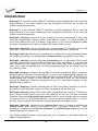
BeeHive204
Very fast universal 4x 48-pindrive concurrent multiprogramming system with ISP capability
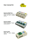
BeeHive4+
Fast universal 4x 48-pindrive concurrent multiprogramming system with ISP capability
BeeProg2
Very fast universal 48-pindrive Programmer with USB/LPT interface and ISP capability
BeeProg+
Universal 48-pindrive Programmer with USB/LPT interface and ISP capability
SmartProg2
Universal 40-pindrive Programmer with USB interface and ISP capability
MEMprog2
Universal memory Programmer
T51prog2
MCS51 Series and Atmel AVR Microcontrollers Programmer with ISP capability
PIKprog2
Microchip PICmicro Programmer with ISP capability
SEEprog
Serial EEPROM Programmer
ELNEC s.r.o.
Presov, Slovakia
12th
April 2011
1
ELNEC s. r. o.
This document is copyrighted by ELNEC s.r.o., Presov, Slovakia. All rights reserved. This
document or any part of it may not be copied, reproduced or translated in any form or in any
way without the prior written permission of ELNEC s.r.o.
The control program is copyright ELNEC s.r.o., Presov, Slovakia. The control program or any
part of it may not be analyzed, disassembled or modified in any form, on any medium, for any
purpose.
Information provided in this manual is intended to be accurate at the moment of release, but
we continuously improve all our products. Please consult manual on www.elnec.com.
ELNEC s.r.o. assumes no responsibility for misuse of this manual.
ELNEC s.r.o. reserves the right to make changes or improvements to the product described
in this manual at any time without notice. This manual contains names of companies,
software products, etc., which may be trademarks of their respective owners. ELNEC s.r.o.
respects those trademarks.
COPYRIGHT © 1991 - 2010
ELNEC s.r.o.
2
ELNEC s. r. o.
How to use this manual
This manual explains how to install the control program and how to use your programmer. It
is assumed that the user has some experience with PCs and installation of software. Once
you have installed the control program we recommend you consult the context sensitive
HELP within the control program rather than the printed User's Manual. Revisions are
implemented in the context sensitive help before the printed User’s Manual.
Dear customer,
thank you for purchasing one of the ELNEC
programmer.
_____________________________________
Please, download actual version of manual
from ELNEC WEB site (www.elnec.com), if
current one will be out of date.
3
ELNEC s. r. o.
Table of contents
How to use this manual...................................................................................................................3
Introduction........................................................................................................................................7
Products configuration ....................................................................................................................9
PC requirements ...........................................................................................................................10
Free additional services: ...............................................................................................................11
Quick Start .......................................................................................................................................12
Detailed description ........................................................................................................................15
BeeHive204 / BeeHive4+ .................................................................................................................16
Introduction ...................................................................................................................................17
BeeHive204 / BeeHive4+ elements ..............................................................................................19
Manipulation with the programmed device ...................................................................................20
In-system serial programming by BeeHive204 / BeeHive4+ ........................................................20
Selftest and calibration check .......................................................................................................22
Technical specification..................................................................................................................24
BeeProg2 / BeeProg+......................................................................................................................29
Introduction ...................................................................................................................................30
BeeProg2 / BeeProg+ elements ...................................................................................................32
Connecting BeeProg2 / BeeProg+ to the PC................................................................................33
Manipulation with the programmed device ...................................................................................34
In-system serial programming by BeeProg2 / BeeProg+..............................................................34
Multiprogramming by BeeProg2 / BeeProg+ ................................................................................36
Selftest and calibration check .......................................................................................................36
Technical specification..................................................................................................................37
SmartProg2 ......................................................................................................................................42
Introduction ...................................................................................................................................43
SmartProg2 elements ...................................................................................................................44
Connecting SmartProg2 to PC......................................................................................................45
Manipulation with the programmed device ...................................................................................45
In-system serial programming by SmartProg2..............................................................................46
Selftest ..........................................................................................................................................47
Technical specification..................................................................................................................47
MEMprog2 ........................................................................................................................................51
Introduction ...................................................................................................................................52
MEMprog2 elements .....................................................................................................................53
Connecting MEMprog2 to PC .......................................................................................................54
Manipulation with the programmed device ...................................................................................54
Selftest ..........................................................................................................................................54
Technical specification..................................................................................................................55
T51prog2 ..........................................................................................................................................58
Introduction ...................................................................................................................................59
T51prog2 elements .......................................................................................................................60
Connecting T51prog2 to PC .........................................................................................................61
Manipulation with the programmed device ...................................................................................61
In-System serial programming by T51prog2.................................................................................61
Selftest ..........................................................................................................................................62
Technical specification..................................................................................................................63
PIKprog2...........................................................................................................................................65
Introduction ...................................................................................................................................66
PIKprog2 elements .......................................................................................................................67
4
ELNEC s. r. o.
Connecting PIKprog2 programmer to PC..................................................................................... 68
Manipulation with the programmed device ................................................................................... 68
In-System serial programming by PIKprog2................................................................................. 68
Selftest.......................................................................................................................................... 69
Technical specification ................................................................................................................. 70
SEEprog ........................................................................................................................................... 73
Introduction................................................................................................................................... 74
SEEprog elements........................................................................................................................ 75
Connecting SEEprog programmer to PC ..................................................................................... 75
Manipulation with the programmed device ................................................................................... 76
Technical specification ................................................................................................................. 76
Setup ................................................................................................................................................ 78
Software setup.............................................................................................................................. 79
Hardware setup ............................................................................................................................ 85
Pg4uw .............................................................................................................................................. 89
Pg4uw-the programmer software ................................................................................................. 90
File................................................................................................................................................ 93
Buffer ............................................................................................................................................ 99
Device......................................................................................................................................... 105
Programmer................................................................................................................................ 132
Options ....................................................................................................................................... 137
Help ............................................................................................................................................ 147
Pg4uwMC....................................................................................................................................... 150
Common notes .............................................................................................................................. 160
Maintenance ............................................................................................................................... 161
Software ..................................................................................................................................... 162
Hardware .................................................................................................................................... 168
ISP (In-System Programming).................................................................................................... 168
Other........................................................................................................................................... 171
Troubleshooting and warranty .................................................................................................... 173
Troubleshooting.......................................................................................................................... 174
If you have an unsupported target device .................................................................................. 175
Warranty terms ........................................................................................................................... 175
5
ELNEC s. r. o.
Conventions used in the manual
References to the control program functions are in bold, e.g. Load, File, Device, etc.
References to control keys are written in brackets <>, e.g. <F1>.
Terminology used in the manual:
Device
ZIF socket
Buffer
Printer port
USB port
HEX data format
any kind of programmable integrated circuits or programmable devices
Zero Insertion Force socket used for insertion of target device
part of memory or disk, used for temporary data storage
type of PC port (parallel), which is primarily dedicated for printer
connection.
type of PC port (serial), which is dedicated for connecting portable and
peripheral devices.
format of data file, which may be read with standard text viewers; e.g.
byte 5AH is stored as characters '5' and 'A', which mean bytes 35H and
41H. One line of this HEX file (one record) contains start address and
data bytes. All records are secured with checksum.
6
Introduction
Introduction
7
ELNEC s. r. o.
This user's manual covers these ELNEC programmers: BeeHive204, BeeHive4+, BeeProg2,
BeeProg+, SmartProg2, MEMprog2, T51prog2, PIKprog2 and SEEprog.
BeeHive204 is very fast universal 4x 48-pindrive concurrent multiprogramming system
designed for high volume production programming with minimal operator effort. The chips are
programmed at near theoretical maximum programming speed. Using build-in ISP connectors
the programmer is able to program ISP capable chips in-circuit.
BeeHive4+ is fast universal 4x 48-pindrive concurrent multiprogramming system
designed for high volume production programming with minimal operator effort. The chips are
programmed at near theoretical maximum programming speed. Using build-in ISP connectors
the programmer is able to program ISP capable chips in-circuit.
BeeProg2 is a fast universal USB/LPT interfaced universal programmer and logic IC tester
with 48 powerful pindrivers. Using build-in ISP connector the programmer is able to program
ISP capable chips in-circuit. This design allows easily add new devices to the device list.
BeeProg2 is a true universal and a true low cost programmer, providing one of the best
"value for money" in today's market.
BeeProg+ is a fast universal USB/LPT interfaced universal programmer and logic IC tester
with 48 powerful pindrivers. Using build-in ISP connector the programmer is able to program
ISP capable chips in-circuit. This design allows easily add new devices to the device list.
BeeProg+ is a true universal and a true low cost programmer, providing one of the best
"value for money" in today's market.
SmartProg2 is a small, fast and powerful USB interfaced programmer of all kinds of
programmable devices. Using build-in ISP connector the programmer is able to program ISP
capable chips in-circuit. It has design, which allows easily add new devices to the device list.
Nice "value for money" in this class.
MEMprog2 is a small, fast and powerful USB interfaced programmer for EPROM, EEPROM,
Flash EPROM, NVRAM, serial EEPROM and static RAM tester. MEMprog2 can be upgraded
to SmartProg2.
T51prog2 is a small, fast and powerful USB interfaced programmer for MCS51 series and
Atmel AVR microcontrollers with ISP capability. T51prog2 enables also programming serial
EEPROM with interface types IIC (24Cxx), Microwire (93Cxx) and SPI (25Cxx). T51prog2 can
be upgraded to SmartProg2.
PIKprog2 is a small, fast and powerful USB interfaced programmer for PICmicro® family
microcontrollers and serial EEPROM with IIC (24Cxx), Microwire (93Cxx) and SPI (25Cxx)
interface types. Using build-in in-circuit serial programming (ISP) connector programmer is
able to program PICmicro® family microcontrollers using serial algorithms. PIKprog2 can be
upgraded to SmartProg2.
SEEprog is universal programmer of all serial EEPROM in 8 pin DIL package. SEEprog
programs EEPROM with interface IIC, SPI and Microwire, and also specialty as for example
digital thermometers. The programmer supports LV (3.3V) devices too.
All our programmers work with almost any IBM PC Pentium compatible or higher, portable or
desktop personal computers. Programmers use the USB port or parallel (printer) port of PC.
8
Introduction
All programmers function flawlessly on Windows operating system (see section PC
requirement).
All programmers are driven by an easy-to-use, control program with pull-down menus, hot
keys and online help. Control program is common for all the ELNEC programmers.
Advanced design, including protection circuits, original brand components and careful
manufacturing allows us to provide a three-years warranty for BeeHive204, BeeHive4+,
BeeProg2, BeeProg+ and SmartProg2 and one-year warranty for MEMprog2, T51prog2,
PIKprog2 and SEEprog on parts and labor for the programmers (limited 25,000 cycle
warranty on ZIF socket). This warranty terms are valid for customers, who purchase a
programmer directly from Elnec company. The warranty conditions of Elnec sellers may differ
depending on the target country law system or Elnec seller’s warranty policy.
Note: We don’t recommend use programmers MEMprog2 and SEEprog for In-circuit
programming. See FAQ on site www.elnec.com.
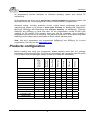
Products configuration
*
PIKprog2
SEEprog
•
•
•
•
T51prog2
1x
1x
4x
4x
MEMprog2
•
•
•
-
SmartProg2
programmer
USB cable
LPT cable
internal power supply
external power supply
diagnostic POD
ISP diagnostic POD
ISP cable
ZIF anti-dust cover
software CD
User’s manual
Quick Guide
registration card
shipping case
BeeProg2
BeeProg+
BeeHive204
BeeHive4+
Before installing and using your programmer, please carefully check that your package
includes all next mentioned parts. If you find any discrepancy with respective parts list and/or
if any of these items are damaged, please contact your distributor immediately.
•
•
*
•
•
•
•
•
•
•
•
•
•
•
•
•
•
•
•
•
•
•
•
•
•
•
•
•
•
•
•
•
•
•
•
•
•
•
•
•
•
•
•
•
•
•
•
•
•
•
•
•
•
•
•
•
•
•
•
optional accessories
9
ELNEC s. r. o.
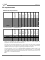
PC requirements
BeeHive204
BeeHive4+
BeeProg2
BeeProg+
SmartProg2
MEMprog2
T51prog2
PIKprog2
SEEprog
OS - Windows
CPU
RAM [MB]
free disk space [MB]
USB 2.0 high speed
USB 1.1
LPT
CDROM
2x BeeHive204
2x BeeHive4+
Minimal PC requirements
XP
C2D 2,6GHz
1000
400
2000
P4
512
200
98
P4
256
200
98
P4
256
200
98
P4
256
200
98
P4
256
200
98
P4
256
200
95
P4
256
200
•
•
•
•
•
•
•
•
•
•
•
•
•
•
•
•
•
BeeHive204
BeeHive4+
BeeProg2
BeeProg+
SmartProg2
MEMprog2
T51prog2
PIKprog2
SEEprog
OS - Windows
CPU
RAM [MB]
free disk space [MB]
USB 2.0 high speed
LPT IEEE1284
2x BeeHive204
2x BeeHive4+
Recommended PC requirements
XP
C2Quad
2000
2000
XP
C2D
1000
1000
XP
C2D
1000
1000
XP
C2D
512
1000
XP
C2D
512
1000
XP
C2D
512
1000
XP
C2D
512
1000
XP
C2D
512
1000
•
-
•
-
•
•
•
-
•
-
•
-
•
-
•
These PC requirements are valid for 2.66/01.2010 version of control program for
programmers. For other version see www.elnec.com.
Free disk space requirement depends also on used IC device size and number of attached
programming sites. For large devices the required free space on disk will be approximately
1000MB + 2x Device size x number of programming sites attached to this PC.
Very easy indication, if your PC in hardware/software configuration is good enough for the
current software version and current situation with PG4UW/PG4UWMC, is to run Windows
task manager (Ctrl+Alt+Del) and see the performance folder. It have to be max. 80% of CPU
usage at full run of programming system.
Note:
10
Introduction
For convenience, we suggest that you use a supplementary multi I/O card to provide an
additional printer port (LPT2 for example), in order to avoid sharing the same LPT port
between printer and programmer.
Free additional services:
Why is it important to use the latest version of the control
program?
• Semiconductor manufacturers continuously introduce new devices with new package types,
manufactured by new technologies in order to support the need for flexibility, quality and
speed in product design and manufacturing. To keep pace and to keep you up-to-date, we
usually implement more than 5000 new devices into the control program within a year.
• Furthermore, a typical programmable device undergoes several changes during its lifetime
in an effort to maintain or to improve its technical characteristics and process yields. These
changes often impact with the programming algorithms, which need to be upgraded (the
programming algorithm is a set of instructions that tells the programmer how to program
data into a particular target device). Using the newest algorithms in the programming
process is the key to obtaining high quality results. In many cases, while the older algorithm
will still program the device, they may not provide the level of data retention that would be
possible with an optimal algorithm. Failure to not use the most current algorithm can
decrease your programming yields (more improper programmed target devices), and may
often increase programming times, or even affect the long term reliability of the programmed
device.
• We are making mistakes too...
Our commitment is to implement support for these new or modified parts before or as soon as
possible after their release, so that you can be sure that you are using latest and/or optimal
programming algorithms that were created for this new device.
• free technical support (phone/fax/e-mail).
• free lifetime software update via Web site.
Free software updates are available from our
Internet address www.elnec.com.
We also offer the following new services in our customer support program: Keep-Current and
AlgOR.
• Keep-Current is a service by which ELNEC ships to you the latest version of the control
program for programmer and the updated user documentation. A Keep-Current service is
your hassle-free guarantee that you always have access to the latest software and
documentation, at minimal cost. For more information see www.elnec.com.
• AlgOR (Algorithm On Request) service allows you to receive from ELNEC software support
for programming devices not yet available in the current device list. For more information
see www.elnec.com.
11
ELNEC s. r. o.
Quick Start
12
Quick Start
Installing programmer hardware
• connect the USB (or LPT) port of programmer to a USB (or printer) port of PC using
supplied cable
• connect the connector of the power supply adapter to the programmer or turn on
programmer by switch
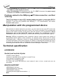
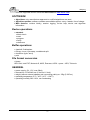
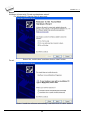
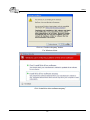
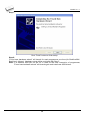
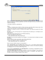
Installing the programmer software
Run the installation program from the CD (Setup.exe) and follow the on-screen instructions.
Please, for latest information about the programmer hardware and software see
www.elnec.com.
Run the control program
Double click on
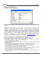
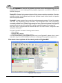
After start, control program Pg4uw automatically scans all existing ports and searches for any
connected ELNEC programmer. Program Pg4uw is common for all ELNEC programmers
hence Pg4uw will try to find all supported programmers.
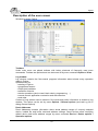
Menu File is used for source files manipulation, settings and viewing directory, changes
drives, changes start and finish address of buffer for loading and saving files and loading and
saving projects.
Menu Buffer is used for buffer manipulation, block operation, filling a part of buffer with string,
erasing, checksum and of course editing and viewing with other items (find and replace
string, printing...).
Menu Device is used for a work with selected programmable device: select, read, blank
check, program, verify, erase and setting of programming process, serialization and
associated file control.
Menu Programmer is used for work with programmer.
Menu Options is used to view and change various default settings.
Menu Help is used for view supported devices and programmers and information about
program version.
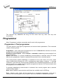
Programming a device
1. select device: click on
2. load data into buffer:
a)
from file: click on
b)
from device: insert device to ZIF and click on
3. insert target device to ZIF
13
ELNEC s. r. o.
4. check, if the device is blank: click on
5. program device: click on
6. additional verify of device: click on
14
Detailed description
Detailed description
15
ELNEC s. r. o.
BeeHive204 / BeeHive4+
16
BeeHive204 / BeeHive4+
Introduction
BeeHive204 is very fast universal 4x 48-pindrive concurrent multiprogramming system
designed for high volume production programming with minimal operator effort. The chips are
programmed at near theoretical maximum programming speed.
BeeHive4+ is fast universal 4x 48-pindrive concurrent multiprogramming system
designed for high volume production programming with minimal operator effort. The chips are
programmed at near theoretical maximum programming speed.
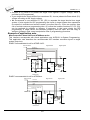
BeeHive204 / BeeHive4+ consist of four independent isolated universal programming
modules, based on the BeeProg2 / BeeProg+ programmer hardware. Therefore the sockets
can run asynchronously (concurrent programming mode). Each programming module starts
programming at the moment the chip is detected to be inserted in the socket properly independently on the status of other programming modules. It result three programming
modules works while you replace the programmed chip at the fourth.
Modular construction of hardware - the programming modules works independently - allows
for continuing operation when a part of the circuit becomes inoperable. It also makes service
quick and easy.
Hands-free operation: asynchronous and concurrent operation allows a chip to begin
programming immediately upon insertion of a chip. The operator merely removes the finished
chip and inserts a new chip. Operator training is therefore minimized...
BeeHive204 / BeeHive4+ support all kinds of types and silicon technologies of today and
tomorrow programmable devices without family-specific module. You can be sure the next
devices support require the software update and (if necessary) simple package converter
(programming adapter), therefore the ownership cost are minimized.
Using built-in in-circuit serial programming (ISP) connector, the programmer is able to
program ISP capable chips in circuit.
BeeHive204 / BeeHive4+ provide very competitive price coupled with excellent hardware
design for reliable programming. It has probably best "value for money" programmer in this
class.
BeeHive204 / BeeHive4+ provide very fast programming due to high-speed FPGA driven
hardware and execution of time-critical routines inside of the programmer. It is at least so fast
than competitors in this category, for many chips much faster than most competitors. As a
result, when used in production this programmer waits for an operator, and not the other way
round.
BeeHive204 / BeeHive4+ interfaces with the IBM PC/compatible, portable or desktop
personal computers through USB (2.0) port.
BeeHive204 / BeeHive4+ provides a banana jack for ESD wrist straps connection to easy-toimplement the ESD protection control and also other banana jack for earth wire.
17
ELNEC s. r. o.
FPGA based totally reconfigurable 48 powerful TTL pindrivers provide H/L/pull_up/pull_down
and read capability for each pin of socket. Advanced pindrivers incorporate high-quality highspeed circuitry to deliver signals without overshoot or ground bounce for all supported
devices. Pin drivers operate down to 1.8V so you'll be ready to program the full range of
today's advanced low-voltage devices.
BeeHive204 / BeeHive4+ performs on each programming module device insertion test
(wrong or backward position) and contact check (poor contact pin-to-socket) before it
programs each device. These capabilities, supported by overcurrent protection and
signature-byte check help prevent chip damage due to operator error.
BeeHive204 / BeeHive4+ have the selftest capability, which allows run diagnostic part of
software to thoroughly check the health of the each programming module.
BeeHive204 / BeeHive4+ have a built-in protection circuits for eliminate damage of
programmer and/or programmed device due to environment or operator failure. All ZIF socket
pins of BeeHive204 / BeeHive4+ programmer are protected against ESD up to 15kV.
BeeHive204 / BeeHive4+ perform programming verification at the marginal level of supply
voltage, which, obviously, improves programming yield, and guarantees long data retention.
Various socket converters are available to handle device in PLCC, SOIC, PSOP, SSOP,
TSOP, TSSOP, TQFP, QFN (MLF), SDIP, BGA and other packages.
BeeHive204 / BeeHive4+ programmer is driven by an easy-to-use control program with pulldown menu, hot keys and on-line help. Selecting of device is performed by its class, by
manufacturer or simply by typing a fragment of vendor name and/or part number.
Standard device-related commands (read, blank check, program, verify, erase) are boosted
by some test functions (insertion test, signature-byte check), and some special functions
(autoincrement, production mode - start immediately after insertion of chip into socket).
All known data formats are supported. Automatic file format detection and conversion during
load of file.
The rich-featured autoincrement function enables to assign individual serial numbers to
each programmed device - or simply increments a serial number, or the function enables to
read serial numbers or any programmed device identification signatures from a file.
The software also provides a lot of information about programmed device. As a special, the
drawings of all available packages, explanation of chip labeling (the meaning of prefixes
and suffixes at the chips) for each supported chip are provided.
The software provide full information for ISP implementation: Description of ISP connector
pins for currently selected chip, recommended target design around in-circuit programmed
chip and other necessary information.
The remote control feature allows Pg4uw software to be flow controlled by other application
– either using .BAT file commands or using DLL file. For BeeHive204 / BeeHive4+ is remote
control limited for ISP programming only. Please use BeeHive204AP for automated off line
programming.
18
BeeHive204 / BeeHive4+
Jam files of JEDEC standard JESD-71 are interpreted by Jam Player. Jam files are
generated by design software which is provided by manufacturer of respective programmable
device. Chips are programmed in ZIF or through ISP connector (IEEE 1149.1 Joint Test
Action Group (JTAG) interface).
VME files are interpreted by VME Player. VME file is a compressed binary variation of SVF
file and contains high-level IEEE 1149.1 bus operations. VME files are generated by design
software which is provided by manufacturer of respective programmable device. Chips are
programmed in ZIF or through ISP connector (IEEE 1149.1 Joint Test Action Group (JTAG)
interface).
Multiple devices are possible to program and test via JTAG chain: JTAG chain (ISP-Jam) or
JTAG chain (ISP-VME).
It is important to remember that in most cases new devices require only a software update
due to the BeeHive204 / BeeHive4+ is truly universal programmer. With our prompt service
you can have new devices can be added to the current list within hours!
Advanced design including protection circuits, original brand components and careful
manufacturing and burning allows us to provide a three-year warranty on parts and labor for
the BeeHive204 / BeeHive4+ (limited 25,000-cycle warranty on ZIF socket).
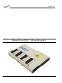
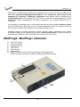
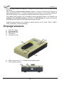
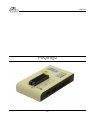
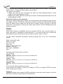
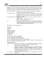
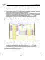
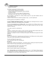
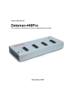
BeeHive204 / BeeHive4+ elements
1)
2)
3)
4)
5)
6)
48 pin ZIF socket
work result LEDs
power/sleep LED of site
YES! Button
ISP connector
LED indicator power
19
ELNEC s. r. o.
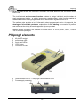
7)
8)
9)
power supply connector
power switch
"GND" connector can be used for grounding of the programmer
"ESD wrist strap" connector is place for attaching of ESD wrist strap
10) temperature controlled fans
11) type B USB connector for PC ↔ BeeHive204 / BeeHive4+ communication cable
Manipulation with the programmed device
After selection of desired device for your work, you can insert it into the open ZIF socket (the
lever is up) and close socket (the lever is down). The correct orientation of the programmed
device in ZIF socket is shown on the picture near ZIF socket on the programmer's cover. The
programmed device is necessary to insert into the socket also to remove from the socket
when LED BUSY light off.
Note: Programmer's protection electronics protect the target device and the programmer
itself against either short or long-term power failures and, partly, also against a PC failure.
However, it is not possible to grant the integrity of the target device due to incorrect, userselected programming parameters. Target device may be not destroyed by forced interruption
of the control program (reset or switch-off PC), by removing the physical connection to the
programmer, but the content of actually programmed cell may remains undefined. Don't
unplug the target device from the ZIF socket during work with devices (LED BUSY shine).
In-system serial programming by BeeHive204 /
BeeHive4+
Optimized advanced pindriver deliver programming performance without overshoot or ground
bounce for all device technologies. Pin drivers operate down to 1.8V so you'll be ready to
program the full range of today's advanced low- voltage devices.
The ISP programming solution performs programming verification at the marginal level of
supply voltage, which, obviously, improves programming yield, and guarantees long data
retention.
The ISP programming solution provides also the power supply for the target system.
This ISP programming solution provides very competitive price but excellent hardware design
for reliable programming.
20
BeeHive204 / BeeHive4+
The software provide full information for ISP implementation: Description of ISP connector
pins for currently selected chip, recommended target design around in-circuit programmed
chip and other necessary information.
For general definition, recommendation and direction about ISP see section Common notes
/ ISP please.
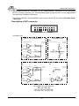
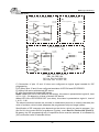
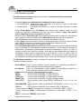
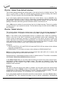
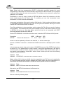
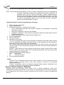
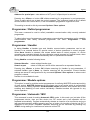
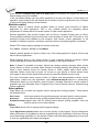
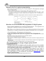
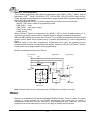
Description of ISP connector
2
4
6
8
10 12 14 16 18 20
1
3
5
7
9
11 13 15 17 19
Front view at ISP connector.
H/L/read driver
pins 3, 5, 7, 9, 11, 13 of ISP connector
A)
pin 14 of ISP connector
B)
pin of ISP
connector
drivers in programmer
drivers in programmer
pin of ISP
connector
VCC
RA1
H/L
Float
RB2
Read
RA2
Pull-up/
Pull-down
RA3
RB1
YES!
GND
pins 15, 16 of ISP connector
C)
D)
drivers in programmer
CC1
pin of ISP
connector
Float
pin of ISP
connector
RD1
H/L
RC1
GND
E)
Read
CE1
Pull-up/
Pull-down
H/L
RC2
RE1
RA1 180R, RA2 1k3, RA3 22k,
RB1 10k, RB2 10k,
CC1 1n, RC1 1k3, RC2 22k,
RD1 22k, CE1 1n, RE1 1k3,
21
pin of ISP
connector
ELNEC s. r. o.
C) Connection of pins 15 and 16 when are configured as logical signal needed for ISP
programming
D) E) When pins 15 and 16 are configured as status of LED OK and LED ERROR
D) before first action with desired ISP device
E) after first action with desired ISP device
Notes: When LED OK or LED ERROR ON (shine), this status is presented as logical H, level
of H is 1,8V - 5V depend on H level of desired ISP device.
When LED OK or LED ERROR OFF (not shine), this status is presented as logical L, level of
L is 0V - 0,4V.
The above mentioned values are provided to understand (and also to exactly calculate) the
value of resistors, which isolate (separate) the programmed chip and target system.
Specification of ISP connector pins depends on the device, which you want to program. You
can find it in the control SW for programmer (Pg4uw), menu Device / Device Info (Ctrl+F1).
Be aware, the ISP programming way of respective device must be selected. It is indicated by
(ISP) suffix after name of selected device.
These specifications correspond with application notes published of device manufacturers.
Used application notes you may find on www.elnec.com, section Support / Application
Notes.
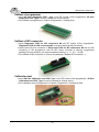
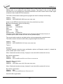
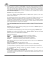
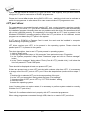
Note: Pin no. 1 is signed by triangle scratch on ISP cable connectors.
BeeHive204 / BeeHive4+ ISP cable
Warnings:
• Use only attached ISP cable. When you use other ISP cable (other material, length…),
programming may occur unreliable.
• BeeHive204 / BeeHive4+ can supply programmed device (pin 1 of ISP connector) and
target system (pin 19, 20 of ISP connector) with limitation (see Technical specification /
ISP connector).
• BeeHive204 / BeeHive4+ apply programming voltage to target device and checks his
value (target system can modify programming voltage). If the programming voltage is
different as expected, no action with target device will be executed.
Selftest and calibration check
If you feel that your programmer does not react according to your expectation, please run the
programmer (ISP connector) selftest using Diagnostic POD (Diagnostic POD for ISP
connectors #2), enclosed with the standard delivery package.
22
BeeHive204 / BeeHive4+
Selftest of programmer
• Insert 48 pins diagnostic POD - type I into ZIF socket of the programmer. 48 pins
diagnostic POD - type I must be inserted as 48 pins device.
• Run selftest of programmer in Pg4uw (Programmer / Selftest plus).
Selftest of ISP connector
• Insert Diagnostic POD for ISP connectors #2 into ZIF socket of the programmer.
Diagnostic POD for ISP connectors #2 must be inserted as 48 pins device.
• Interconnect 20 pins connector of Diagnostic POD for ISP connectors #2 with an ISP
connector of the programmer with an ISP cable, included in delivery programmer
package. Be sure that pins are interconnected properly (i.e. 1-1, 2-2... 20-20).
• Run selftest of ISP connector in Pg4uw (Programmer / Selftest ISP connector…).
Calibration test
• Insert 48 Pins Calibration test POD, Type I into ZIF socket of the programmer. 48 Pins
Calibration test POD, Type I must be inserted as 48 pins device.
• Run calibration test of programmer in Pg4uw (Programmer / Calibration test).
23
ELNEC s. r. o.
Technical specification
Specification
system)
•
•
•
•
•
•
(BeeHive204
/
BeeHive4+
multiprogramming
4x universal programming module (4x 48-pin DIL ZIF sockets)
operation result LEDs, LED power
USB 2.0 high-speed compatible port
line power input 100-240VAC/60W max.
banana jack for ESD wrist straps connection
banana jack for connection to ground
Specification (valid for each programming module)
HARDWARE
Base unit, DACs
• USB 2.0 high-speed compatible port, up to 480 Mb/s transfer rate
• on-board intelligence: powerful microprocessor and FPGA based state machine
• three D/A converters for VCCP, VPP1, and VPP2, controllable rise and fall time
• VCCP range 0..8V/1A
• VPP1, VPP2 range 0..26V/1A
• selftest capability
ZIF sockets, pindriver
• 48-pin DIL ZIF (Zero Insertion Force) socket accepts both 300/600 mil devices up to 48-pin
• pindrivers: 48 universal
• VCCP/VPP1/VPP2 can be connected to each pin
• perfect ground for each pin
• FPGA based TTL driver provides H, L, CLK, pull-up, pull-down on all pindriver pins
• analog pindriver output level selectable from 1.8 V up to 26V
• current limitation, overcurrent shutdown, power failure shutdown
• ESD protection on each pin of socket (IEC1000-4-2: 15kV air, 8kV contact)
• continuity test: each pin is tested before every programming operation
ISP connector
• 20-pin male type with miss insertion lock
• 6 TTL pindrivers, provides H, L, CLK, pull-up, pull-down; level H selectable from 1.8V up to
5V to handle all (low-voltage including) devices.
• 1x VCCP voltage (range 2V..7V/100mA)
• programmed chip voltage (VCCP) with both source/sink capability and voltage sense
• 1x VPP voltage (range 2V..25V/50mA)
• Target system power supply voltage (range 2V..6V/250mA)
24
BeeHive204 / BeeHive4+
• ESD protection on each pin of ISP connector (IEC1000-4-2: 15kV air, 8kV contact)
• two output signals, which indicate state of work result = LED OK and LED Error (active
level: min 1.8V)
• input signal, switch YES! equivalent (active level: max 0.8V)
DEVICE SUPPORT
Programmer, in ZIF socket
• EPROM: NMOS/CMOS, 27xxx and 27Cxxx series, with 8/16 bit data width, full support for
LV series
• EEPROM: NMOS/CMOS, 28xxx, 28Cxxx, 27EExxx series, with 8/16 bit data width
• Flash EPROM: 28Fxxx, 29Cxxx, 29Fxxx, 29BVxxx, 29LVxxx, 29Wxxx, 49Fxxx series, from
256Kbit to 1Gbit, with 8/16 bit data width, full support for LV series
• Serial E(E)PROM: 24Cxxx, 24Fxxx, 25Cxxx, 45Dxxx, 59Cxxx, 25Fxxx, 25Pxxx, 85xxx,
93Cxxx, NVM3060, MDAxxx series, full support for LV series
• Configuration (EE)PROM: XCFxxx, XC17xxxx, XC18Vxxx, EPCxxx, AT17xxx, 37LVxx
• 1-Wire E(E)PROM: DS1xxx, DS2xxx
• PROM: AMD, Harris, National, Philips/Signetics, Tesla, TI
• NV RAM: Dallas DSxxx, SGS/Inmos MKxxx, SIMTEK STKxxx, XICOR 2xxx, ZMD U63x
series
• PLD: Altera: MAX 3000A, MAX 7000A, MAX 7000B, MAX 7000S, MAX7000AE, MAX II
• PLD: Lattice: ispGAL22V10x, ispLSI1xxx, ispLSI1xxxEA, ispLSI2xxx, ispLSI2xxxA,
ispLSI2xxxE, ispLSI2xxxV, ispLSI2xxxVE, ispLSI2xxxVL, LC4xxxB/C/V/ZC, M4-xx/xx,
M4A3-xx/xx, M4A5-xx/xx, M4LV-xx/xx
• PLD: Xilinx: XC9500, XC9500XL, XC9500XV, Coolrunner XPLA3, Coolrunner-II
• other PLD: SPLD/CPLD series: AMI, Atmel, AMD-Vantis, Gould, Cypress, ICT, Lattice, NS,
Philips, STM, VLSI, TI
• Microcontrollers 48 series: 87x41, 87x42, 87x48, 87x49, 87x50 series
• Microcontrollers 51 series: 87xx, 87Cxxx, 87LVxx, 89Cxxx, 89Sxxx, 89LVxxx, all
manufacturers, Philips LPC series
• Microcontrollers Intel 196 series: 87C196 KB/KC/KD/KT/KR/...
• Microcontrollers Atmel AVR: AT90Sxxxx, ATtiny, ATmega series
• Microcontrollers Cypress: CY7Cxxxxx, CY8Cxxxxx
• Microcontrollers ELAN: EM78Pxxx
• Microcontrollers MDT 1xxx and 2xxx series
• Microcontrollers Microchip PICmicro: PIC10xxx, PIC12xxx, PIC16xxx, PIC17Cxxx,
PIC18xxx, PIC24xxx, dsPIC series
• Microcontrollers Motorola (Freescale): 68HC05, 68HC08, 68HC11, HCS08, HCS12 series
• Microcontrollers Myson MTV2xx, 3xx, 4xx and 5xx series
• Microcontrollers National: COP8xxx series
• Microcontrollers NEC: uPD78Fxxx series
• Microcontrollers Novatek: NT68xxx series
• Microcontrollers Scenix (Ubicom): SXxxx series
• Microcontrollers SGS-Thomson: ST6xx, ST7xx, ST10xx, STR7xx series
• Microcontrollers TI: MSP430 and MSC121x series
• Microcontrollers ZILOG: Z86/Z89xxx and Z8xxx series
• Microcontrollers other: EM Microelectronic, Fujitsu, Goal Semiconductor, Hitachi, Holtek,
Princeton, Macronix, Winbond, Infineon(Siemens), Samsung, Toshiba, ...
25
ELNEC s. r. o.
I.C. Tester
• TTL type: 54,74 S/LS/ALS/H/HC/HCT series
• CMOS type: 4000, 4500 series
• static RAM: 6116.. 624000
• user definable test pattern generation
Programmer, through ISP connector
• Serial E(E)PROM: IIC series, MW series, SPI series, KEELOQ series, serial data Flash,
PLD configuration memories
• Microcontrollers Atmel: AT89Sxxx, AT90Sxxxx, ATtiny, ATmega series
• Microcontrollers Cypress: CY8C2xxxx
• Microcontrollers Elan: EM78Pxxx, EM6xxx series
• Microcontrollers EM Microelectronic: 4 and 8 bit series
• Microcontrollers Microchip PICmicro: PIC10xxx, PIC12xxx, PIC16xxx, PIC17xxx, PIC18xxx,
PIC24xxx, dsPIC series
• Microcontrollers Motorola/Freescale: HC11 series, HC908 series (both 5-wire, All-wire),
HCS08, HCS12
• Microcontrollers NEC: uPD7xxx series
• Microcontrollers Philips: LPC2xxx series, LPC series, 89xxx series
• Microcontrollers Scenix (Ubicom): SXxxx series
• Microcontrollers TI: MSP430 (both JTAG and BSL series), MSC12xxx series
• PLD: Lattice: ispGAL22xV10x, ispLSI1xxxEA, ispLSI2xxxE, ispLSI2xxxV, ispLSI2xxxVE,
ispLSI2xxxVL, M4-xx/xx, M4LV-xx/xx, M4A3-xx/xx, M4A5-xx/xx, LC4xxxB/C/V/ZC
• Various PLD (also by JAM player/JTAG support):
• Altera: MAX 3000A, MAX 7000A, MAX 7000B, MAX 7000S, MAX 9000, MAX II
• Xilinx: XC9500, XC9500XL, XC9500XV, Coolrunner XPLA3, Coolrunner-II
Notes:
For all supported devices see actual Device list on www.elnec.com.
Package support
• support all devices in DIP with default socket
• package support includes DIP, SDIP, PLCC, JLCC, SOIC, SOP, PSOP, SSOP, TSOP,
TSOPII, TSSOP, QFP, PQFP, TQFP, VQFP, QFN (MLF), SON, BGA, EBGA, FBGA,
VFBGA, UBGA, FTBGA, LAP, CSP, SCSP etc.
• support devices in non-DIP packages up to 48 pins with universal adapters
• programmer is compatible with third-party adapters for non-DIP support
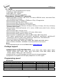
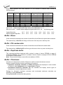
Programming speed
BeeHive204
Device
Am29DL640G (parallel NOR Flash)
K8P6415UQB (parallel NOR Flash)
K9F1G08U0M (parallel NAND Flash)
QB25F640S33 (serial Flash)
AT89C51RD2 (microcontroller)
PIC32MX360F512L (microcontroller)
Conditions:
Size [bits]
400080Hx16 (64 Mega)
400100Hx16 (64 Mega)
8400000Hx8 (1 Giga)
800200Hx8 (64 Mega)
10000Hx8
80000Hx8
Operation
programming and verify
programming and verify
programming and verify
programming and verify
programming and verify
programming and verify
P4, 2.4GHz, 512MB RAM, USB2.0, Windows XP
26
Time
24 sec
13 sec
122.7 sec
30.7 sec
14.4 sec
16.2 sec
BeeHive204 / BeeHive4+
BeeHive4+
Device
M50FW080 (parallel Flash)
MX28F640C3BT (parallel Flash)
K9F1G08U0M (parallel NAND Flash)
AT45D081 (serial Flash)
AT89C51RD2 (microcontroller)
PIC18LF452 (microcontroller)
Conditions:
Size [bits]
100000Hx8 (8 Mega)
400000Hx16 (64 Mega)
8400000Hx8 (1 Giga)
108000Hx8 (16 Mega)
10000Hx8
4000Hx16
Operation
programming and verify
programming and verify
programming and verify
programming and verify
programming and verify
programming and verify
Time
22 sec
57 sec
239 sec
36 sec
15 sec
4 sec
P4, 2.4GHz, 512MB RAM, USB2.0, Windows XP
SOFTWARE
• Algorithms: only manufacturer approved or certified algorithms are used.
• Algorithm updates: software updates are available regularly, approx. every 4 weeks, free
of charge (Internet download). OnDemand version of software is available for highly
needed chips support and/or bugs fixes. Available nearly daily.
• Main features: revision history, session logging, on-line help, device and algorithm
information
Device operations
• standard:
• intelligent device selection by device type, manufacturer or typed fragment of part name
• automatic ID-based selection of EPROM/Flash EPROM
• blank check, read, verify
• program
• erase
• configuration and security bit program
• illegal bit test
• checksum
• interpret the Jam Standard Test and Programming Language (STAPL), JEDEC standard
JESD-71
• interpret the VME files compressed binary variation of SVF files
• security
• insertion test, reverse insertion check
• contact check
• ID byte check
• special
• production mode (automatic start immediately after device insertion)
• lot of serialization modes (more type of incremental modes, from-file mode, custom
generator mode)
• statistic
• count-down mode
Buffer operations
• view/edit, find/replace
• fill/copy, move, byte swap, word/dword split
• checksum (byte, word)
• print
27
ELNEC s. r. o.
File load/save
• no download time because programmer is PC controlled
• automatic file type identification/recognition
Supported file formats
• unformatted (raw) binary
• HEX: Intel, Intel EXT, Motorola S-record, MOS, Exormax, Tektronix, ASCII-SPACE-HEX,
ASCII HEX
• Altera POF, JEDEC (ver. 3.0.A), e.g. from ABEL, CUPL, PALASM, TANGO PLD, OrCAD
PLD, PLD Designer ISDATA, etc.
• JAM (JEDEC STAPL Format), JBC (Jam STAPL Byte Code), STAPL (STAPL File)
JEDEC standard JESD-71
• VME (ispVME file VME2.0/VME3.0)
GENERAL
• supply voltage AC 100-240V, max. 1.2A, 50-60Hz
• power consumption max. 60W active
• dimensions 361x234x56 mm (14.2x9.2x2.2 inch)
• weight (programmer) 3.5kg (7.7 lb)
• operating temperature 5°C ÷ 40°C (41°F ÷ 104°F)
• operating humidity 20%..80%, non condensing
28
BeeProg2 / BeeProg+
BeeProg2 / BeeProg+
29
ELNEC s. r. o.
Introduction
BeeProg2 is a very fast universal USB/LPT interfaced universal programmer built to meet the
strong demand of the small manufacturing and developer’s community for the fast and
reliable universal programmer.
BeeProg+ is a fast universal USB/LPT interfaced universal programmer built to meet the
strong demand of the small manufacturing and developer’s community for the fast and
reliable universal programmer.
BeeProg2 / BeeProg+ support all kinds of types and silicon technologies of today and
tomorrow programmable devices without family-specific module. You have freedom to
choose the optimal device for your design. Using built-in in-circuit serial programming (ISP)
connector, the programmer is able to program ISP capable chips in circuit.
BeeProg2 / BeeProg+ aren’t only programmer, but also tester of TTL/CMOS logic ICs and
memories. Furthermore, it allows generating user-definable test pattern sequences.
BeeProg2 / BeeProg+ provide very competitive price coupled with excellent hardware design
for reliable programming. It is probably best "value for money" programmer in this class.
BeeProg2 / BeeProg+ provide very fast programming due to high-speed FPGA driven
hardware and execution of time-critical routines inside of the programmer. It is at least fast
than competitors in this category, for many chips much faster than most competitors. As a
result, when used in production this one-socket-programmer waits for an operator, and not
the other way round.
BeeProg2 / BeeProg+ interfaces with the IBM PC Pentium compatible or higher, portable or
desktop personal computers through USB (2.0/1.1) port or any standard parallel (printer) port.
Programmer can utilize power of both USB high-speed port and IEEE1284 (ECP/EPP) highspeed parallel port. Support of both USB/LPT port connections gives you the choice to
connect the BeeProg2 / BeeProg+ programmer to any PC, from latest notebook to older
desktop without USB port.
BeeProg2 / BeeProg+ provides a banana jack for ESD wrist straps connection to easy-toimplement the ESD protection control and also other banana jack for earth wire.
BeeProg2 / BeeProg+ have a FPGA based totally reconfigurable 48 powerful TTL pindrivers,
where provide H/L/pull_up/pull_down and read capability for each pin of socket. Advanced
pindrivers incorporate high-quality high-speed circuitry to deliver signals without overshoot
or ground bounce for all supported devices. Improved pindrivers operate down to 1.8V so
you'll be ready to program the full range of today's advanced low-voltage devices.
BeeProg2 / BeeProg+ performs device insertion test (wrong or backward position) and
contact check (poor contact pin-to-socket) before it programs each device. These
capabilities, supported by overcurrent protection and signature-byte check help prevent
chip damage due to operator error.
The selftest capability allows running diagnostic part of software to thoroughly check the
health of the programmer.
30
BeeProg2 / BeeProg+
Built-in protection circuits eliminate damage of programmer and/or programmed device due
environment or operator failure. All the inputs of the BeeProg2 / BeeProg+ programmer,
including the ZIF socket, ISP connector, connection to PC and power supply input, are
protected against ESD up to 15kV.
BeeProg2 / BeeProg+ programmer performs programming verification at the marginal
level of supply voltage, which, obviously, improves programming yield, and guarantees long
data retention.
Various socket converters are available to handle device in PLCC, SOIC, PSOP, SSOP,
TSOP, TSSOP, TQFP, QFN (MLF), SDIP, BGA and other packages.
BeeProg2 / BeeProg+ programmer is driven by an easy-to-use control program with pulldown menu, hot keys and on-line help. Selecting of device is performed by its class, by
manufacturer or simply by typing a fragment of vendor name and/or part number.
Standard device-related commands (read, blank check, program, verify, erase) are boosted
by some test functions (insertion test, signature-byte check), and some special functions
(autoincrement, production mode - start immediately after insertion of chip into socket).
All known data formats are supported. Automatic file format detection and conversion during
load of file.
The rich-featured autoincrement function enables to assign individual serial numbers to
each programmed device - or simply increments a serial number, or the function enables to
read serial numbers or any programmed device identification signatures from a file.
The software also provides a lot of information about programmed device. As a special, the
drawings of all available packages, explanation of chip labeling (the meaning of prefixes
and suffixes at the chips) for each supported chip are provided.
The software provide full information for ISP implementation: Description of ISP connector
pins for currently selected chip, recommended target design around in-circuit programmed
chip and other necessary information.
The remote control feature allows being Pg4uw software flow controlled by other application
– either using .BAT file commands or using DLL file. DLL file, examples
(C/PAS/VBASIC/.NET) and manual are part of standard software delivery.
Jam files of JEDEC standard JESD-71 are interpreted by Jam Player. Jam files are
generated by design software which is provided by manufacturer of respective programmable
device. Chips are programmed in ZIF or through ISP connector (IEEE 1149.1 Joint Test
Action Group (JTAG) interface).
VME files are interpreted by VME Player. VME file is a compressed binary variation of SVF
file and contains high-level IEEE 1149.1 bus operations. VME files are generated by design
software which is provided by manufacturer of respective programmable device. Chips are
programmed in ZIF or through ISP connector (IEEE 1149.1 Joint Test Action Group (JTAG)
interface).
Multiple devices are possible to program and test via JTAG chain: JTAG chain (ISP-Jam) or
JTAG chain (ISP-VME).
31
ELNEC s. r. o.
Attaching of more BeeProg2 / BeeProg+ programmers to the same PC (through USB port) is
achieved a powerful multiprogramming system, which support as many chips, as are
supported by BeeProg2 / BeeProg+ programmer and without obvious decreasing of
programming speed. It is important to know, there is a concurrent multiprogramming - each
programmer works independently and each programmer can program different chip, if
necessary.
It is important to remember that in most cases new devices require only a software update
due to the BeeProg2 / BeeProg+ is truly universal programmer. With our prompt service you
can have new devices can be added to the current list within hours!
Advanced design including protection circuits, original brand components and careful
manufacturing and burning allows us to provide a three-year warranty on parts and labor for
the BeeProg2 / BeeProg+ (limited 25,000-cycle warranty on ZIF socket).
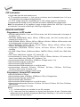
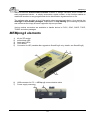
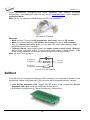
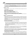
BeeProg2 / BeeProg+ elements
1)
2)
3)
4)
5)
6)
7)
48 pin ZIF socket
work result LEDs
power/sleep LED
YES! Button
ISP connector
power switch
"GND" connector can be used for grounding of the programmer
"ESD wrist strap" connector is place for attaching of ESD wrist strap
32
BeeProg2 / BeeProg+
8) Power supply connector
9) LPT connector for PC ↔ BeeProg2 / BeeProg+ communication cable
10) USB connector for PC ↔ BeeProg2 / BeeProg+ communication cable
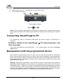
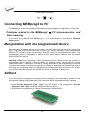
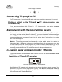
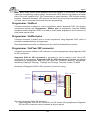
Connecting BeeProg2 / BeeProg+ to the PC
Using USB port
In this case, order of connecting USB cable and power supply to programmer is irrelevant.
Using LPT port
Switch off PC and programmer. Insert the communication cable included with your BeeProg2
/ BeeProg+ programmer package to a free printer port on your PC. If your computer is
equipped with only one printer port, substitute the programmer cable for the printer cable.
Connect the opposite cable end to the programmer. Screw on both connectors to counterconnectors. This is very important. It may be uncomfortable to switch between printer cable
and programmer cable, though it is not recommended to operate the BeeProg2 / BeeProg+
programmer through a mechanical printer switch. Use of an electronic printer switch is
impossible. But you can install a second multi-I/O in your computer, thus obtaining a
supplementary printer port, says LPT2. So your printer may remain on LPT1 while the
programmer on LPT2.
Switch on the PC.
Connect the connector “8” to a mains plug using attached cable. At this time all 'work result'
LEDs (and 'POWER' LED) light up successive and then switch off. Once the POWER LED
lights with low brightness then the BeeProg2 / BeeProg+ programmer is ready to run.
Next run the control program for BeeProg2 / BeeProg+.
Caution! If you don't want to switch off your PC when connecting the BeeProg2 / BeeProg+,
proceed as follows:
• When connecting the programmer to the PC: FIRST insert the communications cable
and THEN the power-supply connector.
• When disconnecting the programmer from the PC: FIRST disconnect the power-supply
connector and THEN the communication cable.
From BeeProg2 / BeeProg+ point of view the connecting and disconnecting sequence is
irrelevant. Protection circuits on all programmer inputs keep it safe. But think of your PC
please.
33
ELNEC s. r. o.
Problems related to the BeeProg2
interconnection, and their removing
If you have any problems with BeeProg2 / BeeProg+
Common notes please.
/
BeeProg+
PC
PC interconnection, see section
Manipulation with the programmed device
After selection of desired device for your work, you can insert into the open ZIF socket (the
lever is up) and close socket (the lever is down). The correct orientation of the programmed
device in ZIF socket is shown on the picture near ZIF socket on the programmer's cover. The
programmed device is necessary to insert into the socket also to remove from the socket
when LED BUSY light off.
Note: Programmer's protection electronics protect the target device and the programmer
itself against either short or long-term power failures and, partly, also against a PC failure.
However, it is not possible to grant the integrity of the target device due to incorrect, userselected programming parameters. Target device may be not destroyed by forced interruption
of the control program (reset or switch-off PC), by removing the physical connection to the
programmer, but the content of actually programmed cell may remains undefined. Don't
unplug the target device from the ZIF socket during work with device (LED BUSY shine).
In-system serial programming by BeeProg2 /
BeeProg+
For general definition, recommendation and direction about ISP see section Common notes
/ ISP please.
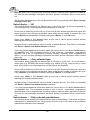
Description of ISP connector
2
4
6
8
10 12 14 16 18 20
1
3
5
7
9
11 13 15 17 19
Front view at ISP connector of programmer.
34
BeeProg2 / BeeProg+
H/L/read driver
pins 3, 5, 7, 9, 11, 13 of ISP connector
A)
pin 14 of ISP connector
B)
pin of ISP
connector
drivers in programmer
drivers in programmer
pin of ISP
connector
VCC
RA1
H/L
Float
RB2
Read
RA2
Pull-up/
Pull-down
RA3
RB1
YES!
GND
pins 15, 16 of ISP connector
C)
D)
drivers in programmer
CC1
pin of ISP
connector
Float
pin of ISP
connector
RD1
H/L
RC1
GND
E)
Read
CE1
Pull-up/
Pull-down
pin of ISP
connector
H/L
RC2
RE1
RA1 180R, RA2 1k3, RA3 22k,
RB1 10k, RB2 10k,
CC1 1n, RC1 1k3, RC2 22k,
RD1 22k, CE1 1n, RE1 1k3,
C) Connection of pins 15 and 16 when are configured as logical signal needed for ISP
programming
D) E) When pins 15 and 16 are configured as status of LED OK and LED ERROR
D) before first action with desired ISP device
E) after first action with desired ISP device
Notes: When LED OK or LED ERROR ON (shine), this status is presented as logical H, level
of H is 1,8V - 5V depend on H level of desired ISP device.
When LED OK or LED ERROR OFF (not shine), this status is presented as logical L, level of
L is 0V - 0,4V.
The above mentioned values are provided to understand (and also to exactly calculate) the
value of resistors, which isolate (separate) the programmed chip and target system.
Specification of ISP connector pins depends on the device, which you want to program. You
can find it in the control SW for programmer (Pg4uw), menu Device / Device Info (Ctrl+F1).
Be aware, the ISP programming way of respective device must be selected. It is indicated by
(ISP) suffix after name of selected device.
35
ELNEC s. r. o.
These specifications correspond with application notes published of device manufacturers.
Used application notes you may find on www.elnec.com, section Support / Application
Notes.
Note: Pin no. 1 is signed by triangle scratch on ISP cable connectors.
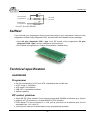
BeeProg2 / BeeProg+ ISP cable
Warnings:
• When you use BeeProg2 / BeeProg+ as ISP programmer, don’t insert device to ZIF
socket.
• When you program devices in ZIF socket, don’t insert ISP cable to ISP connector.
• Use only attached ISP cable. When you use other ISP cable (other material, length…),
programming may occur unreliable.
• BeeProg2 / BeeProg+ can supply programmed device (pin 1 of ISP connector) and
target system (pin 5 of ISP connector) with limitation (see Technical specification / ISP
connector).
• BeeProg2 / BeeProg+ apply programming voltage to target device and checks his value
(target system can modify programming voltage). If the programming voltage is different
as expected, no action with target device will be executed.
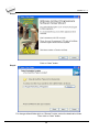
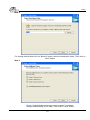
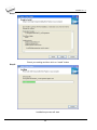
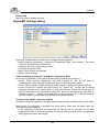
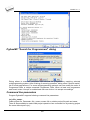
Multiprogramming by BeeProg2 / BeeProg+
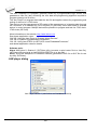
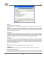
During installation of Pg4uw at Select Additional Tasks window you check, if is allowed install
BeeProg2 / BeeProg+ multiprogramming control support.
For start of BeeProg2 / BeeProg+ multiprogramming is necessary run special control program
Pg4uwMC.exe. At this program user assign BeeProg2 / BeeProg+ to control programs, may
load projects for all BeeProg2 / BeeProg+ and run Pg4uw for every connected and assigned
BeeProg2 / BeeProg+.
Selftest and calibration check
If you feel that your programmer does not react according to your expectation, please run the
programmer (ISP connector) selftest using Diagnostic POD (Diagnostic POD for ISP
connectors #2), enclosed with the standard delivery package.
Selftest of programmer
• Insert 48 pins diagnostic POD - type I into ZIF socket of the programmer. 48 pins
diagnostic POD - type I must be inserted as 48 pins device.
• Run selftest of programmer in Pg4uw (Programmer / Selftest plus).
36
BeeProg2 / BeeProg+
Selftest of ISP connector
• Insert Diagnostic POD for ISP connectors #2 into ZIF socket of the programmer.
Diagnostic POD for ISP connectors #2 must be inserted as 48 pins device.
• Interconnect 20 pins connector of Diagnostic POD for ISP connectors #2 with an ISP
connector of the programmer with an ISP cable, included in delivery programmer
package. Be sure that pins are interconnected properly (i.e. 1-1, 2-2, ..., 20-20).
• Run selftest of ISP connector in Pg4uw (Programmer / Selftest ISP connector…).
Calibration test
• Insert 48 Pins Calibration test POD, Type I into ZIF socket of the programmer. 48 Pins
Calibration test POD, Type I must be inserted as 48 pins device.
• Run calibration test of programmer in Pg4uw (Programmer / Calibration test).
Technical specification
HARDWARE
Base unit, DACs
• USB 2.0 high-speed compatible port, up to 480 Mb/s transfer rate
• FPGA based IEEE 1284 slave printer port, up to 1MB/s transfer rate
• on-board intelligence: powerful microprocessor and FPGA based state machine
37
ELNEC s. r. o.
• three D/A converters for VCCP, VPP1, and VPP2, controllable rise and fall time
• VCCP range 0..8V/1A
• VPP1, VPP2 range 0..26V/1A
• selftest capability
• protection against surge and ESD on power supply input, parallel port connection
• banana jack for ESD wrist straps connection
• banana jack for connection to ground
Socket, pindriver
• 48-pin DIL ZIF (Zero Insertion Force) socket accepts both 300/600 mil devices up to 48-pin
• pindrivers: 48 universal
• VCCP / VPP1 / VPP2 can be connected to each pin
• perfect ground for each pin
• FPGA based TTL driver provides H, L, CLK, pull-up, pull-down on all pindriver pins
• analog pindriver output level selectable from 1.8 V up to 26V
• current limitation, overcurrent shutdown, power failure shutdown
• ESD protection on each pin of socket (IEC1000-4-2: 15kV air, 8kV contact)
• continuity test: each pin is tested before every programming operation
ISP connector
• 20-pin male type with miss insertion lock
• 6 TTL pindrivers, provides H, L, CLK, pull-up, pull-down; level H selectable from 1.8V up to
5V to handle all (low-voltage including) devices.
• 1x VCCP voltage (range 2V..7V/100mA)
• programmed chip voltage (VCCP) with both source/sink capability and voltage sense
• and 1x VPP voltage (range 2V..25V/50mA)
• Target system power supply voltage (range 2V..6V/250mA)
• ESD protection on each pin of ISP connector (IEC1000-4-2: 15kV air, 8kV contact)
• two output signals, which indicate state of work result = LED OK and LED Error (active
level: min 1.8V)
• input signal, switch YES! equivalent (active level: max 0.8V)
DEVICE SUPPORT
Programmer, in ZIF socket
• EPROM: NMOS/CMOS, 2708*, 27xxx and 27Cxxx series, with 8/16 bit data width, full
support for LV series
• EEPROM: NMOS/CMOS, 28xxx, 28Cxxx, 27EExxx series, with 8/16 bit data width
• Flash EPROM: 28Fxxx, 29Cxxx, 29Fxxx, 29BVxxx, 29LVxxx, 29Wxxx, 49Fxxx series, from
256Kbit to 1Gbit, with 8/16 bit data width, full support for LV series
• Serial E(E)PROM: 24Cxxx, 24Fxxx, 25Cxxx, 45Dxxx, 59Cxxx, 25Fxxx, 25Pxxx, 85xxx,
93Cxxx, NVM3060, MDAxxx series, full support for LV series
• Configuration (EE)PROM: XCFxxx, XC17xxxx, XC18Vxxx, EPCxxx, AT17xxx, 37LVxx
• 1-Wire E(E)PROM: DS1xxx, DS2xxx
• PROM: AMD, Harris, National, Philips/Signetics, Tesla, TI
• NV RAM: Dallas DSxxx, SGS/Inmos MKxxx, SIMTEK STKxxx, XICOR 2xxx, ZMD U63x
series
• PLD: Altera: MAX 3000A, MAX 7000A, MAX 7000B, MAX 7000S, MAX7000AE, MAX II
38
BeeProg2 / BeeProg+
• PLD: Lattice: ispGAL22V10x, ispLSI1xxx, ispLSI1xxxEA, ispLSI2xxx, ispLSI2xxxA,
ispLSI2xxxE, ispLSI2xxxV, ispLSI2xxxVE, ispLSI2xxxVL, LC4xxxB/C/V/ZC, M4-xx/xx,
M4A3-xx/xx, M4A5-xx/xx, M4LV-xx/xx
• PLD: Xilinx: XC9500, XC9500XL, XC9500XV, Coolrunner XPLA3, Coolrunner-II
• other PLD: SPLD/CPLD series: AMI, Atmel, AMD-Vantis, Gould, Cypress, ICT, Lattice, NS,
Philips, STM, VLSI, TI
• Microcontrollers 48 series: 87x41, 87x42, 87x48, 87x49, 87x50 series
• Microcontrollers 51 series: 87xx, 87Cxxx, 87LVxx, 89Cxxx, 89Sxxx, 89LVxxx, all
manufacturers, Philips LPC series
• Microcontrollers Intel 196 series: 87C196 KB/KC/KD/KT/KR/...
• Microcontrollers Atmel AVR: AT90Sxxxx, ATtiny, ATmega series
• Microcontrollers Cypress: CY7Cxxxxx, CY8Cxxxxx
• Microcontrollers ELAN: EM78Pxxx
• Microcontrollers MDT 1xxx and 2xxx series
• Microcontrollers Microchip PICmicro: PIC10xxx, PIC12xxx, PIC16xxx, PIC17Cxxx,
PIC18xxx, PIC24xxx, dsPIC series
• Microcontrollers Motorola (Freescale): 68HC05, 68HC08, 68HC11, HCS08, HCS12 series
• Microcontrollers Myson MTV2xx, 3xx, 4xx and 5xx series
• Microcontrollers National: COP8xxx series
• Microcontrollers NEC: uPD78Fxxx series
• Microcontrollers Novatek: NT68xxx series
• Microcontrollers Scenix (Ubicom): SXxxx series
• Microcontrollers SGS-Thomson: ST6xx, ST7xx, ST10xx, STR7xx series
• Microcontrollers TI: MSP430 and MSC121x series
• Microcontrollers ZILOG: Z86/Z89xxx and Z8xxx series
• Microcontrollers other: EM Microelectronic, Fujitsu, Goal Semiconductor, Hitachi, Holtek,
Princeton, Macronix, Winbond, Infineon(Siemens), Samsung, Toshiba, ...
Programmer, through ISP connector
• Serial E(E)PROM: IIC series, MW series, SPI series, KEELOQ series, serial data Flash,
PLD configuration memories
• Microcontrollers Atmel: AT89Sxxx, AT90Sxxxx, ATtiny, ATmega series
• Microcontrollers Cypress: CY8C2xxxx
• Microcontrollers Elan: EM78Pxxx, EM6xxx series
• Microcontrollers EM Microelectronic: 4 and 8 bit series
• Microcontrollers Microchip PICmicro: PIC10xxx, PIC12xxx, PIC16xxx, PIC17xxx, PIC18xxx,
PIC24xxx, dsPIC series
• Microcontrollers Motorola/Freescale: HC11 series, HC908 series (both 5-wire, All-wire),
HCS08, HCS12
• Microcontrollers NEC: uPD7xxx series
• Microcontrollers Philips: LPC2xxx series, LPC series, 89xxx series
• Microcontrollers Scenix (Ubicom): SXxxx series
• Microcontrollers TI: MSP430 (both JTAG and BSL series), MSC12xxx series
• PLD: Lattice: ispGAL22xV10x, ispLSI1xxxEA, ispLSI2xxxE, ispLSI2xxxV, ispLSI2xxxVE,
ispLSI2xxxVL, M4-xx/xx, M4LV-xx/xx, M4A3-xx/xx, M4A5-xx/xx, LC4xxxB/C/V/ZC
• Various PLD (also by JAM player/JTAG support):
Altera: MAX 3000A, MAX 7000A, MAX 7000B, MAX 7000S, MAX 9000, MAX II
Xilinx: XC9500, XC9500XL, XC9500XV, Coolrunner XPLA3, Coolrunner-II
Notes:
• Devices marked * are obsolete, programming with additional module
39
ELNEC s. r. o.
• For all supported devices see actual Device list on www.elnec.com
I.C. Tester
• TTL type: 54,74 S/LS/ALS/H/HC/HCT series
• CMOS type: 4000, 4500 series
• static RAM: 6116.. 624000
• user definable test pattern generation
Package support
• support all devices in DIP with default socket
• package support includes DIP, SDIP, PLCC, JLCC, SOIC, SOP, PSOP, SSOP, TSOP,
TSOPII, TSSOP, QFP, PQFP, TQFP, VQFP, QFN (MLF), SON, BGA, EBGA, FBGA,
VFBGA, UBGA, FTBGA, LAP, CSP, SCSP etc.
• support devices in non-DIP packages up to 48 pins with universal adapters
• programmer is compatible with third-party adapters for non-DIP support
Programming speed
BeeProg2
Device
Am29DL640G (parallel NOR Flash)
K8P6415UQB (parallel NOR Flash)
K9F1G08U0M (parallel NAND Flash)
QB25F640S33 (serial Flash)
AT89C51RD2 (microcontroller)
PIC32MX360F512L (microcontroller)
Conditions:
BeeProg+
Operation
programming and verify
programming and verify
programming and verify
programming and verify
programming and verify
programming and verify
Time
24 sec
13 sec
122.7 sec
30.7 sec
14.4 sec
16.2 sec
P4, 2,4GHz, 512 MB RAM, USB 2.0 HS, Windows XP
Device
M50FW080 (parallel Flash)
MX28F640C3BT (parallel Flash)
K9F1G08U0M (parallel NAND Flash)
AT45D081 (serial Flash)
AT89C51RD2 (microcontroller)
PIC18LF452 (microcontroller)
Conditions:
Size [bits]
400080Hx16 (64 Mega)
400100Hx16 (64 Mega)
8400000Hx8 (1 Giga)
800200Hx8 (64 Mega)
10000Hx8
80000Hx8
Size [bits]
100000Hx8 (8 Mega)
400000Hx16 (64 Mega)
8400000Hx8 (1 Giga)
108000Hx8 (16 Mega)
10000Hx8
4000Hx16
Operation
programming and verify
programming and verify
programming and verify
programming and verify
programming and verify
programming and verify
Time
22 sec
57 sec
239 sec
36 sec
15 sec
4 sec
P4, 2,4GHz, 512 MB RAM, USB 2.0 HS, Windows XP
SOFTWARE
• Algorithms: only manufacturer approved or certified algorithms are used. Custom
algorithms are available at additional cost.
• Algorithm updates: software updates are available regularly, approx. every 4 weeks, free
of charge. OnDemand version of software is available for highly needed chips support
and/or bugs fixes. Available nearly daily.
• Main features: revision history, session logging, on-line help, device and algorithm
information
Device operations
• standard:
• intelligent device selection by device type, manufacturer or typed fragment of part name
• automatic ID-based selection of EPROM/Flash EPROM
40
BeeProg2 / BeeProg+
•
•
•
•
•
•
•
blank check, read, verify
program
erase
configuration and security bit program
illegal bit test
checksum
interprete the Jam Standard Test and Programming Language (STAPL), JEDEC standard
JESD-71
• interprete the VME files compressed binary variation of SVF files
• security
• insertion test, reverse insertion check
• contact check
• ID byte check
• special
• production mode (automatic start immediately after device insertion)
• lot of serialization modes (more type of incremental modes, from-file mode, custom
generator mode)
• statistic
• count-down mode
Buffer operations
• view/edit, find/replace
• fill/copy, move, byte swap, word/dword split
• checksum (byte, word)
• print
File load/save
• no download time because programmer is PC controlled
• automatic file type identification
Supported file formats
• unformatted (raw) binary
• HEX: Intel, Intel EXT, Motorola S-record, MOS, Exormax, Tektronix, ASCII-SPACE-HEX,,
ASCII HEX
• Altera POF, JEDEC (ver. 3.0.A), e.g. from ABEL, CUPL, PALASM, TANGO PLD, OrCAD
PLD, PLD Designer ISDATA, etc.
• JAM (JEDEC STAPL Format), JBC (Jam STAPL Byte Code), STAPL (STAPL File) JEDEC
standard JESD-71
• VME (ispVME file VME2.0/VME3.0)
GENERAL
• operating voltage 110-250V AC
• power consumption max. 20W active, about 2W sleep
• dimensions 195x140x55 mm (7.7x5.5x2.2 inch)
• weight 0.9kg (1.98 lb)
• operating temperature 5°C ÷ 40°C (41°F ÷ 104°F)
• operating humidity 20%..80%, non condensing
41
ELNEC s. r. o.
SmartProg2
42
SmartProg2
Introduction
SmartProg2 is next member of new generation of Windows based ELNEC universal
programmers. Programmer is built to meet the demands of the development labs and field
engineers to universal, but portable programmer.
SmartProg2 is a small, fast and powerful programmer of all kinds of programmable devices.
Using build-in in-circuit serial programming (ISP) connector the programmer is able to
program ISP capable chips in-circuit. SmartProg2 isn't only a programmer, but also a static
RAM tester.
SmartProg2 provides very competitive price with excellent hardware design for reliable
programming. Nice "value for money" in this class.
SmartProg2 provides very fast programming due to high-speed FPGA driven hardware and
USB 2.0 full speed port.
SmartProg2 interfaces with the IBM PC Pentium compatible or higher, portable or desktop
personal computers through USB port, what is important for new, LPT-port-less computers
(notebooks for example).
SmartProg2 has 40 powerful TTL pindrivers provide H/L/pull_up/pull_down and read
capability for each pin of socket. Advanced pindrivers incorporate high-quality high-speed
circuitry to deliver signals without overshoot or ground bounce for all supported devices. Pin
drivers operate down to 1.8V so you'll be ready to program the full range of today's advanced
low-voltage devices.
The programmer performs device insertion test (wrong device position in socket) and
contact check (poor contact pin-to-socket) before it programs each device. These
capabilities, supported by signature-byte check help prevent chip damage due to operator
error.
SmartProg2 programmer performs programming verification at the marginal level of supply
voltage, which, obviously, improves programming yield, and guarantees long data retention.
SmartProg2 programmer is driven by an easy-to-use control program with pull-down menu,
hot keys and on-line help. Selecting of device is performed by its class, by manufacturer or
simply by typing a fragment of vendor name and/or part number.
Standard device-related commands (read, blank check, program, verify, erase) are boosted
by some test functions (insertion test, signature-byte check), and some special functions
(autoincrement).
All known data formats are supported. Automatic file format detection and conversion during
load of file.
The rich-featured autoincrement function enables to assign individual serial numbers to
each programmed device - or simply increments a serial number, or the function enables to
read serial numbers or any programmed device identification signatures from a file.
43
ELNEC s. r. o.
The software also provides a lot of information about programmed device. As a special, the
drawings of all available packages, explanation of chip labeling (the meaning of prefixes
and suffixes at the chips) for each supported chip are provided.
The software provide full information for ISP implementation: Description of ISP connector
pins for currently selected chip, recommended target design around in-circuit programmed
chip and other necessary information.
Various socket converters are available to handle device in PLCC, SOIC, SSOP, TSOP,
TSSOP, TQFP, QFN (MLF) and other packages.
Advanced design of the SmartProg2 programmer and careful manufacturing and burning
allows us to provide a three-year warranty on parts and labor for the programmer (limited 25
000-cycle warranty on ZIF socket).
SmartProg2 elements
1)
2)
3)
4)
5)
40 pin ZIF socket
power/sleep LED
work result LEDs
YES! Button
Connector for ISP
44
SmartProg2
6)
7)
USB connector for PC ↔ SmartProg2 communication cable
Power supply connector
Power supply connector
+
Note: Due to low power consumption of SmartProg2 in inactive state, it doesn't require power
switch. When the power LED indicator glows with a low intensity the SmartProg2 is in inactive
mode.
Connecting SmartProg2 to PC
For SmartProg2 order of connecting USB cable and power supply to programmer is
irrelevant.
Problems related to the SmartProg2
their removing
If you have any problems with SmartProg2
notes please.
PC interconnection, and
PC interconnection, see section Common
Manipulation with the programmed device
After selection of desired device for your work, you can insert into the open ZIF socket (the
lever is up) and close socket (the lever is down). The correct orientation of the programmed
device in ZIF socket is shown on the picture near ZIF socket on the programmer's cover. The
programmed device is necessary to insert into the socket also to remove from the socket
when LED BUSY light off.
Warning: SmartProg2 programmer hasn’t protection devices, which protect the content of
programmed device against critical situations, for example power failures and PC failure
(interrupted cable...). Moreover, a device is usually destroyed in the programming mode due
to forced interruption of the control program run (Reset or switching the computer off) due to
removing the connecting cable, or unplugging the programmed device from the ZIF socket.
Incorrectly placed device in the ZIF socket can cause its damage or destruction.
45
ELNEC s. r. o.
In-system serial programming by SmartProg2
For general definition, recommendation and direction about ISP see section Common notes
/ ISP please.
Description of SmartProg2 ISP connector
2
4
6
8 10
1
3
5
7
9
Front view at ISP connector of programmer.
Specification of ISP connector pins depends on the device, which you want to program. You
can find it in the control SW for programmer (Pg4uw), menu Device / Device Info (Ctrl+F1).
Be aware, the ISP programming way of respective device must be selected. It is indicated by
(ISP) suffix after name of selected device.
These specifications correspond with application notes published of device manufacturers.
Used application notes you may find on www.elnec.com, section Support / Application
Notes.
Note: Pin no. 1 is signed by triangle scratch on ISP cable connectors.
SmartProg2 ISP cable
Warnings:
• When you use SmartProg2 as ISP programmer, don’t insert device to ZIF socket.
• When you program devices in ZIF socket, don’t insert ISP cable to ISP connector.
• Use only attached ISP cable. When you use other ISP cable (other material, length…),
programming may occur unreliable.
• SmartProg2 can supply programmed device only, but target system cannot supply
SmartProg2.
• SmartProg2 apply programming voltage to target device and checks his value (target
system can modify programming voltage). If the programming voltage is different as
expected, no action with target device will be executed.
Note: H/L/read SmartProg2 driver
46
SmartProg2
C1
H/L/read driver
in programmer
PU/PD driver
in programmer
R1
pin of ISP
connector
R2
C1=1nF, R1=1k3, R2=22k
Selftest
If you feel that your programmer does not react according to your expectation, please run the
programmer selftest using Diagnostic POD, enclosed with the standard delivery package.
• Insert 40 pins diagnostic POD - type I into ZIF socket of the programmer. 40 pins
diagnostic POD - type I must be inserted as 40 pins device.
• Run selftest of programmer in Pg4uw (Programmer / Selftest plus).
Technical specification
HARDWARE
Programmer
•
•
•
•
•
two D/A converters for VCCP and VPP, controllable rise and fall time
VCCP range 2..7V/350mA
VPP range 2..25V/200mA
USB 2.0/1.1 compatible interface
selftest capability
ZIF socket, pindriver
• 40-pin DIL ZIF (Zero Insertion Force) socket accepts both 300/600 mil devices up to 40-pins
• pindriver: 40 TTL pindrivers, universal GND/VCC/VPP pindriver
• FPGA based TTL driver provides H, L, CLK, pull-up, pull-down on all pindriver pins, level H
selectable from 1.8 V up to 5V
• continuity test: each pin is tested before every programming operation
47
ELNEC s. r. o.
ISP connector
• 10-pin male type with miss insertion lock
• 6 TTL pindrivers, provides H, L, CLK, pull-up, pull-down; level H selectable from 1.8V up to
5V to handle all (low-voltage including) devices.
• 1x VCCP voltage (range 2V..7V/100mA) and 1x VPP voltage (range 2V..25V/50mA)
• programmed chip voltage (VCCP) with both source/sink capability and voltage sense
Note: the programmer is not capable to supply a target system from VCCP pin. If you have
such demand, use please a BeeProg2 / BeeProg+ programmer
DEVICE SUPPORT
Programmer, in ZIF socket
• EPROM: NMOS/CMOS, 27xxx and 27Cxxx series, with 8/16 bit data width, full support of
LV series (*1*2)
• EEPROM: NMOS/CMOS, 28xxx, 28Cxxx, 27EExxx series, with 8/16 bit data width, full
support of LV series (*1*2)
• Flash EPROM: 28Fxxx, 29Cxxx, 29Fxxx, 29BVxxx, 29LVxxx, 29Wxxx, 49Fxxx series, with
8/16 bit data width, full support of LV series (*1*2)
• Serial E(E)PROM: 24Cxxx, 24Fxxx, 25Cxxx, 45Dxxx, 59Cxxx, 25Fxxx, 25Pxxx, 85xxx,
93Cxxx, full support for LV series (*1)
• Configuration (EE)PROM: XCFxxx, 37LVxx, XC17xxxx, EPCxxx, AT17xxx, LV series
including
• NV RAM: Dallas DSxxx, SGS/Inmos MKxxx, SIMTEK STKxxx, XICOR 2xxx, ZMD U63x
series
• PLD: Atmel, AMD-Vantis, Cypress, ICT, Lattice, NS,...(*1)
• microcontrollers 51 series: 87Cxxx, 87LVxx, 89Cxxx, 89Sxxx, 89LVxxx, LPC series from
Atmel, Atmel W&M, Intel, Philips, SST, Winbond (*1*2)
• microcontrollers Atmel AVR: ATtiny, AT90Sxxx, ATmega series (*1*2)
• Microcontrollers Cypress: CY8Cxxxxx
• Microcontrollers ELAN: EM78Pxxx
• Microcontrollers EM Microelectronic: 4 and 8 bit series
• microcontrollers Microchip PICmicro: PIC10xxx, PIC12xxx, PIC16xxx, PIC17Cxxx,
PIC18xxx, dsPIC series, 8-40 pins (*1*2)
• microcontrollers Scenix (Ubicom): SXxxx series
Programmer, through ISP connector
• Serial E(E)PROM: IIC series
• Microcontrollers Atmel: AT89Sxxx, AT90Sxxxx, ATtiny, ATmega series
• Microcontrollers Cypress: CY8C2xxxx
• Microcontrollers Elan: EM78Pxxx
• Microcontrollers EM Microelectronic: 4 and 8 bit series
• Microcontrollers Microchip PICmicro: PIC10xxx, PIC12xxx, PIC16xxx, PIC17xxx, PIC18xxx,
dsPIC series
• Microcontrollers Philips: LPC series
Notes:
• (*1) - suitable adapters are available for non-DIL packages
• (*2) - there exist only few adapters for devices with more than 40 pins. Therefore think
please about more powerful programmer (BeeProg2 / BeeProg+), if you need to program
devices with more than 40 pins
48
SmartProg2
• For all supported devices see actual Device list on www.elnec.com.
I.C. Tester
• Static RAM: 6116..624000
Programming speed
Device
Operation
Mode
Time
27C010
AT29C040A
AM29F040
PIC16C67
PIC18F452
AT89C52
PIC16F876A
PIC12C508
programming and verify
programming and verify
programming and verify
programming and verify
programming and verify
programming and verify
programming and verify
programming and verify
in ZIF
in ZIF
in ZIF
in ZIF
in ZIF
in ZIF
ISP
ISP
24 sec
32 sec
69 sec
10 sec
7 sec
17 sec
5 sec
3 sec
Conditions:
P4, 2,4GHz, USB 2.0 HS, Windows XP, Pg4uw 2.11
SOFTWARE
• Algorithms: only manufacturer approved or certified algorithms are used. Custom
algorithms are available at additional cost.
• Algorithm updates: software updates are available approx. every 4 weeks, free of charge.
• Main features: revision history, session logging, on-line help, device and algorithm
information
Device operations
• standard:
• intelligent device selection by device type, manufacturer or typed fragment of part name
• blank check, read, verify
• program
• erase
• configuration and security bit program
• illegal bit test
• checksum
• security
• insertion test
• contact check
• ID byte check
• special
• auto device serial number increment
• statistic
• count-down mode
Buffer operations
•
•
•
•
view/edit, find/replace
fill, copy, move, byte swap, word/dword split
checksum (byte, word)
print
49
ELNEC s. r. o.
File load/save
• no download time because programmer is PC controlled
• automatic file type identification
Supported file formats
• unformatted (raw) binary
• HEX: Intel, Intel EXT, Motorola S-record, MOS, Exormax, Tektronix, ASCII-SPACE-HEX
• JEDEC (ver. 3.0.A), for example from ABEL, CUPL, PALASM, TANGO PLD, OrCAD PLD,
PLD Designer ISDATA etc.
GENERAL
•
•
•
•
•
•
operating voltage 15..20V DC, max. 500mA
power consumption max. 6W active, 1.4W inactive
dimensions 160x97x35 mm (6.3x3.8x1.4 inch)
weight (without external power adapter) ca. 500g (17.65 oz)
operating temperature 5°C ÷ 40°C (41°F ÷ 104°F)
operating humidity 20%..80%, non condensing
50
MEMprog2
MEMprog2
51
ELNEC s. r. o.
Introduction
MEMprog2 is next member of new generation of Windows based ELNEC specialized
programmers. Programmer is built to meet the demands of the development labs and field
engineers for a specialized memory programmer.
MEMprog2 can be upgraded to SmartProg2 using Xprog2 to SmartProg2 upgrade kit
(ord.no.60-0048).
MEMprog2 is small, fast and powerful programmer for virtually all memory types - EPROM,
EEPROM, NVRAM, Flash EPROM and serial EEPROM - low voltage types including.
MEMprog2 isn't only programmer, but also static RAM tester.
MEMprog2 provides very competitive price with excellent hardware design for reliable
programming. Nice "value for money" in this class.
MEMprog2 provides very fast programming due to high-speed FPGA driven hardware and
USB 2.0 full speed port.
MEMprog2 interfaces with the IBM PC Pentium compatible or higher, portable or desktop
personal computers through USB port, what is important for new, LPT-port-less computers
(notebooks for example).
MEMprog2 has 40 powerful TTL pindrivers provide H/L/pull_up/pull_down and read
capability for each pin of socket. Advanced pindrivers incorporate high-quality high-speed
circuitry to deliver signals without overshoot or ground bounce for all supported devices. Pin
drivers operate down to 1.8V so you'll be ready to program the full range of today's advanced
low-voltage devices.
The programmer performs device insertion test (wrong device position in socket) and
contact check (poor contact pin-to-socket) before it programs each device. These
capabilities, supported by signature-byte check help prevent chip damage due to operator
error.
MEMprog2 performs programming verification at the marginal level of supply voltage,
which, obviously, improves programming yield, and guarantees long data retention.
MEMprog2 is driven by an easy-to-use control program with pull-down menus, hot keys and
on-line help. Selecting of device is performed by its class, by manufacturer or simply by
typing a fragment of vendor name and/or part number.
Standard device-related commands (read, blank check, program, verify, erase) are
enhanced by some test functions (insertion test, signature-byte check), and some special
functions (autoincrement).
All known data formats are supported. Automatic file format detection and conversion during
load of file.
52
MEMprog2
The rich-featured autoincrement function enables to assign individual serial numbers to
each programmed device - or simply increments a serial number, or the function enables to
read serial numbers or any programmed device identification signatures from a file.
The software also provides a lot of information about programmed device. As a special, the
drawings of all available packages, explanation of chip labeling (the meaning of prefixes
and suffixes at the chips) for each supported chip are provided.
Various socket converters are available to handle device in PLCC, SOIC, SSOP, TSOP,
TSSOP and other packages.
MEMprog2 elements
1)
2)
3)
4)
5)
40 pin ZIF socket
power/sleep LED
work result LEDs
YES! Button
Connector for ISP (useable after upgrade to SmartProg2 only, details: see SmartProg2)
6)
7)
USB connector for PC ↔ MEMprog2 communication cable
Power supply connector
53
ELNEC s. r. o.
Power supply connector
+
Connecting MEMprog2 to PC
For MEMprog2 order of connecting USB cable and power supply to programmer is irrelevant.
Problems related to the MEMprog2
their removing
If you have any problems with MEMprog2
notes please.
PC interconnection, and
PC interconnection, see section Common
Manipulation with the programmed device
After selection of desired device for your work, you can insert into the open ZIF socket (the
lever is up) and close socket (the lever is down). The correct orientation of the programmed
device in ZIF socket is shown on the picture near ZIF socket on the programmer's cover. The
programmed device is necessary to insert into the socket also to remove from the socket
when LED BUSY light off.
Warning: MEMprog2 programmer hasn’t protection devices, which protect the content of
programmed device against critical situations, for example power failures and PC failure
(interrupted cable...). Moreover, a device is usually destroyed in the programming mode due
to forced interruption of the control program run (Reset or switching the computer off) due to
removing the connecting cable, or unplugging the programmed device from the ZIF socket.
Incorrectly placed device in the ZIF socket can cause its damage or destruction.
Selftest
If you feel that your programmer does not react according to your expectation, please run the
programmer selftest using Diagnostic POD, enclosed with the standard delivery package.
• Insert 40 pins diagnostic POD - type I into ZIF socket of the programmer. 40 pins
diagnostic POD - type I must be inserted as 40 pins device.
• Run selftest of programmer in Pg4uw (Programmer / Selftest plus).
54
MEMprog2
Technical specification
HARDWARE
Programmer
•
•
•
•
•
two D/A converters for VCCP and VPP, controllable rise and fall time
VCCP range 0..7V/350mA
VPP range 0..25V/200mA
USB 2.0/1.1 compatible interface
selftest capability
ZIF socket, pindriver
• 40-pin DIL ZIF (Zero Insertion Force) socket accepts both 300/600 mil devices up to 40-pins
• pindriver: 40 TTL pindrivers, specialized GND/VCC/VPP pindriver
• FPGA based TTL driver provides H, L, CLK, pull-up, pull-down on all pindriver pins, level H
selectable from 1.8 V up to 5V
• continuity test: each pin is tested before every programming operation
ISP connector (useable after upgrade to SmartProg2 only)
• 10-pin male type with miss insertion lock
• 6 TTL pindrivers, provides H, L, CLK, pull-up, pull-down; level H selectable from 1.8V up to
5V to handle all (low-voltage including) devices.
• 1x VCCP voltage (range 2V..7V/100mA) and 1x VPP voltage (range 2V..25V/50mA)
• programmed chip voltage (VCCP) with both source/sink capability and voltage sense
DEVICE SUPPORT
Programmer
• EPROM: NMOS/CMOS, 2708(*3), 27xxx and 27Cxxx series, with 8/16 bit data width, full
support of LV series (*1*2)
• EEPROM: NMOS/CMOS, 28xxx, 28Cxxx, 27EExxx series, with 8/16 bit data width, full
support of LV series (*1*2)
• Flash EPROM: 28Fxxx, 29Cxxx, 29Fxxx, 29BVxxx, 29LVxxx, 29Wxxx, 49Fxxx series, with
8/16 bit data width, full support of LV series (*1*2)
• Serial E(E)PROM: 24Cxxx, 24Fxxx, 25Cxxx, 45Dxxx, 59Cxxx, 25Fxxx, 25Pxxx, NVM3060,
MDA206x (*3), 85xxx, 93Cxxx, full support for LV series (*1)
• Configuration (EE)PROM: 37LVxx, XC17xxxx, AT17xxx, LV series including (*1)
• NV RAM: Dallas DSxxx, SGS/Inmos MKxxx, SIMTEK STKxxx, XICOR 2xxx, ZMD U63x
series
Notes:
• (*1) - suitable adapters are available for non-DIL packages
• (*2) - there exist only few adapters for devices with more than 40 pins. Therefore think
please about more powerful programmer(BeeProg2 / BeeProg+), if you need to program
devices with more than 40 pins
• (*3) - programming with additional module
55
ELNEC s. r. o.
• For all supported devices see actual Device list on www.elnec.com.
I.C. Tester
• Static RAM: 6116..624000
Programming speed
Device
Operation
Mode
Time
27C010
AT29C040A
AM29F040
programming and verify
programming and verify
programming and verify
in ZIF
in ZIF
in ZIF
24 sec
32 sec
69 sec
Conditions:
P4, 2,4GHz, USB 2.0 HS, Windows XP
SOFTWARE
• Algorithms: only manufacturer approved or certified algorithms are used.
• Algorithm updates: software updates are available approx. every 2 weeks, free of charge.
• Main features: revision history, session logging, on-line help, device and algorithm
information
Device operations
• standard:
• intelligent device selection by device type, manufacturer or typed fragment of part name
• blank check, read, verify
• program
• erase
• illegal bit test
• checksum
• security
• insertion test
• contact check
• ID byte check
• special
• auto device serial number increment
• statistic
• count-down mode
Buffer operations
•
•
•
•
view/edit, find/replace
fill, copy, move, byte swap, word/dword split
checksum (byte, word)
print
File load/save
• no download time because programmer is PC controlled
• automatic file type identification
56
MEMprog2
Supported file formats
• unformatted (raw) binary
• HEX: Intel, Intel EXT, Motorola S-record, MOS, Exormax, Tektronix, ASCII-SPACE-HEX
GENERAL
•
•
•
•
•
•
operating voltage 15..20V DC, max. 500mA
power consumption max. 6W active, 1.4W inactive
dimensions 160x97x35 mm (6.3x3.8x1.4 inch)
weight (without external power adapter) ca. 500g (17.65 oz)
operating temperature 5°C ÷ 40°C (41°F ÷ 104°F)
operating humidity 20%..80%, non condensing
57
ELNEC s. r. o.
T51prog2
58
T51prog2
Introduction
T51prog2 is next member of new generation of Windows based ELNEC specialized
programmers. Programmer is capable to support all today available microcontrollers of
MCS51 series (up to 40 pins) and AVR microcontrollers (8-40 pins) by parallel and serial way.
T51prog2 has been developed in close cooperation with Atmel W&M, therefore programmer's
hardware is focused to support all current and future microcontrollers of Atmel W&M MCS51
family.
T51prog2 can be upgraded to SmartProg2 using Xprog2 to SmartProg2 upgrade kit
(ord.no.60-0048).
T51prog2 is small, fast and powerful programmer for MCS51 series and Atmel AVR
microcontrollers. T51prog2 enables also programming of serial EEPROM with IIC (24Cxx),
Microwire (93Cxx) and SPI (25Cxx) interface types. Using build-in in-circuit serial
programming (ISP) connector programmer is capable to program MCS51 family
microcontrollers and Atmel AVR microcontrollers in serial way.
T51prog2 provides very competitive price but excellent hardware design for reliable
programming. Nice "value for money" in this class.
T51prog2 provides very fast programming due to high-speed FPGA driven hardware and
USB 2.0 full speed port.
T51prog2 interfaces with the IBM PC Pentium compatible or higher, portable or desktop
personal computers through USB port, what is important for new, LPT-port-less computers
(notebooks for example).
T51prog2 has 40 powerful TTL pindrivers provide H/L/pull_up/pull_down and read capability
for each pin of socket. Advanced pindrivers incorporate high-quality high-speed circuitry to
deliver programming without overshoot or ground bounce for all supported devices. Pin
drivers operate down to 1.8V so you'll be ready to program the full range of today's advanced
low-voltage devices.
The programmer performs device insertion test (wrong or backward position) and contact
check (poor contact pin-to-socket) before it programs each device. These capabilities,
supported by signature-byte check help prevent chip damage due to operator error.
T51prog2 performs programming verification at the marginal level of supply voltage, which,
obviously, improves programming yield, and guarantees long data retention
T51prog2 programmer is driven by an easy-to-use control program with pull-down menu, hot
keys and on-line help. Selecting of device is performed by its class, by manufacturer or
simply by typing a fragment of vendor name and/or part number.
Standard device-related commands (read, blank check, program, verify, erase) are boosted
by some test functions (insertion test, signature-byte check), and some special functions
(autoincrement).
59
ELNEC s. r. o.
All known data formats are supported. Automatic file format detection and conversion during
load of file.
The rich-featured autoincrement function enables to assign individual serial numbers to
each programmed device - or simply increments a serial number, or the function enables to
read serial numbers or any programmed device identification signatures from a file.
The software also provides a lot of information about programmed device. As a special, the
drawings of all available packages, explanation of chip labeling (the meaning of prefixes
and suffixes at the chips) for each supported chip are provided.
Various socket converters are available to handle device in PLCC, SOIC, SSOP, TSSOP,
TQFP, QFN (MLF) and other packages.
T51prog2 elements
1)
2)
3)
4)
5)
40 pin ZIF socket
power/sleep LED
work result LEDs
YES! Button
Connector for ISP
6)
7)
USB connector for PC ↔ T51prog2 communication cable
Power supply connector
60
T51prog2
Power supply connector
+
Connecting T51prog2 to PC
For T51prog2 order of connecting USB cable and power supply to programmer is irrelevant.
Problems related to the T51prog2
their removing
If you have any problems with T51prog2
notes please.
PC interconnection, and
PC interconnection, see section Common
Manipulation with the programmed device
After selection of desired device for your work, you can insert into the open ZIF socket (the
lever is up) and close socket (the lever is down). The correct orientation of the programmed
device in ZIF socket is shown on the picture near ZIF socket on the programmer's cover. The
programmed device is necessary to insert into the socket also to remove from the socket
when LED BUSY light off.
Warning: T51prog2 programmer hasn’t protection devices, which protect the content of
programmed device against critical situations, for example power failures and PC failure
(interrupted cable...). Moreover, a device is usually destroyed in the programming mode due
to forced interruption of the control program run (Reset or switching the computer off) due to
removing the connecting cable, or unplugging the programmed device from the ZIF socket.
Incorrectly placed device in the ZIF socket can cause its damage or destruction.
In-System serial programming by T51prog2
For general definition, recommendation and direction about ISP see section Common notes
/ ISP please.
Description of T51prog2 ISP connector
2
4
6
8 10
1
3
5
7
9
Front view at ISP connector of programmer.
Specification of ISP connector pins depends on the device, which you want to program. You
can find it in the control SW for programmer (Pg4uw), menu Device / Device Info (Ctrl+F1).
Be aware, the ISP programming way of respective device must be selected. It is indicated by
(ISP) suffix after name of selected device.
61
ELNEC s. r. o.
These specifications correspond with Atmel application note AVR910: In-System
Programming. Used application note you may find on www.elnec.com, section Support /
Application Notes.
Note: Pin no. 1 is signed by triangle scratch on ISP cable connectors.
ISP cable of T51prog2
Warnings:
• When you use T51prog2 as ISP programmer, don’t insert device to ZIF socket.
• When you program devices in ZIF socket, don’t insert ISP cable to ISP connector.
• Use only attached ISP cable. When you use other ISP cable (other material, length…),
programming may occur unreliable.
• T51prog2 cannot supply target system and target system cannot supply T51prog2.
Before action with target device T51prog2 check power supply of target system. If this
power supply is different as expected, no action with device will be executed.
Note: H/L/read T51prog2 driver.
C1
R1
H/L/read driver
in programmer
pin of ISP
connector
R2
PU/PD driver
in programmer
C1=1nF, R1=1k3, R2=22k
Selftest
If you feel that your programmer does not react according to your expectation, please run the
programmer selftest using Diagnostic POD, enclosed with the standard delivery package.
• Insert 40 pins diagnostic POD - type I into ZIF socket of the programmer. 40 pins
diagnostic POD - type I must be inserted as 40 pins device.
• Run selftest of programmer in Pg4uw (Programmer / Selftest plus).
62
T51prog2
Technical specification
HARDWARE
Socket, pin drivers and DACs
•
•
•
•
•
two D/A converters for VCCP and VPP, controllable rise and fall time
VCCP range 0..7V/350mA
VPP range 0..25V/200mA
USB 2.0/1.1 compatible interface
selftest capability
ZIF socket, pindriver
• 40-pin DIL ZIF (Zero Insertion Force) socket accepts both 300/600 mil devices up to 40-pins
• pindriver: 40 TTL pindrivers, universal GND/VCC/VPP pindriver
• FPGA based TTL driver provides H, L, CLK, pull-up, pull-down on all pindriver pins, level H
selectable from 1.8 V up to 5V
• continuity test: each pin is tested before every programming operation
ISP connector
• 10-pin male type with miss insertion lock
• 6 TTL pindrivers, provides H, L, CLK, pull-up, pull-down; level H selectable from 1.8V up to
5V to handle all (low-voltage including) devices.
• 1x VCCP voltage (range 2V..7V/100mA) and 1x VPP voltage (range 2V..25V/50mA)
• programmed chip voltage (VCCP) with both source/sink capability and voltage sense
DEVICE SUPPORT
Programmer, in ZIF socket
• microcontrollers MCS51 series: 87Cxxx, 87LVxx, 89Cxxx, 89Sxxx, 89LVxxx, LPC series
from Atmel, Atmel W&M, Intel, Philips, SST, Winbond, ... 8-40 pins (*1)
• microcontrollers Atmel AVR: ATtiny, AT90Sxxx, ATmega series (parallel and serial mode),
8-40 pins (*1)
• Serial E(E)PROM: 24Cxxx, 24Fxxx, 25Cxxx, 59Cxxx, 85xxx, 93Cxxx series
Programmer, through ISP connector
• Microcontrollers Atmel: AT89Sxxx, AT90Sxxxx, ATtiny, ATmega series
• Microcontrollers Philips: LPC series
Note:
For all supported devices see actual Device list on www.elnec.com.
Programming speed
Device
AT89C52
T87C5111
Conditions:
Operation
programming and verify
programming and verify
Time
17 sec
14 sec
P4, 2,4GHz, USB 2.0 HS, Windows XP
63
ELNEC s. r. o.
SOFTWARE
• Algorithms: only manufacturer approved or certified algorithms are used.
• Algorithm updates: software updates are available approx. every 4 weeks, free of charge.
• Main features: revision history, session logging, on-line help, device and algorithm
information
Device operations
• standard:
• intelligent device selection by device type, manufacturer or typed fragment of part name
• blank check, read, verify
• program
• erase
• illegal bit test
• checksum
• security
• insertion test
• contact check
• ID byte check
• special
• auto device serial number increment
• statistic
• count-down mode
Buffer operations
• view/edit, find/replace
• fill/copy, move, byte swap, word/dword split
• checksum (byte, word)
• print
File load/save
• no download time because programmer is PC controlled
• automatic file type identification
Supported file formats
• unformatted (raw) binary
HEX: Intel, Intel EXT, Motorola S, MOS, Exormax, Tektronix, ASCII-space-HEX
GENERAL
•
•
•
•
•
•
operating voltage 15..20V DC, max. 500mA
power consumption max. 6W active, 1.4W inactive
dimensions 160x97x35 mm (6.3x3.8x1.4 inch)
weight (without external power adapter) ca. 500g (17.65 oz)
operating temperature 5°C ÷ 40°C (41°F ÷ 104°F)
operating humidity 20%..80%, non condensing
64
PIKprog2
PIKprog2
65
ELNEC s. r. o.
Introduction
PIKprog2 is next member of the new generation of Windows based ELNEC specialized
TM
programmers. Programmer is capable to support all currently available Microchip
®
PICmicro series microcontrollers (8-40 pins) using parallel and serial algorithms. The
PIKprog2 programmer isn't development grade programmer, but meets all Microchip's
requirements to manufacturing grade of programmers. The PIKprog2 has been developed in
TM
close cooperation with Microchip Company therefore programmer's hardware is focused to
®
support all current and future PICmicro family microcontrollers.
PIKprog2 can be upgraded to SmartProg2 using Xprog2 to SmartProg2 upgrade kit
(ord.no.60-0048).
®
PIKprog2 is a small, fast and powerful programmer for PICmicro family microcontrollers and
serial EEPROM with IIC (24Cxx), Microwire (93Cxx) and SPI (25Cxx) interface types. Using
build-in in-circuit serial programming (ISP) connector programmer is able to program
®
PICmicro family microcontrollers using serial algorithms.
PIKprog2 provides very competitive price but excellent hardware design for reliable
programming. Nice "value for money" in this class.
PIKprog2 provides very fast programming due to high-speed FPGA driven hardware and
USB 2.0 full speed port.
PIKprog2 interfaces with the IBM PC Pentium compatible or higher, portable or desktop
personal computers through USB port, what is important for new, LPT-port-less computers
(notebooks for example).
PIKprog2 has 40 powerful TTL pindrivers provide H/L/pull_up/pull_down and read capability
for each pin of socket. Advanced pindrivers incorporate high-quality high-speed circuitry to
deliver signals without overshoot or ground bounce for all supported devices. Pin drivers
operate down to 1.8V so you'll be ready to program the full range of today's advanced lowvoltage devices.
The programmer performs device insertion test (wrong device position in socket) and
contact check (poor contact pin-to-socket) before it programs each device. These
capabilities, supported by signature-byte check help prevent chip damage due to operator
error.
PIKprog2 programmer performs programming verification at the marginal level of supply
voltage, which, obviously, improves programming yield, and guarantees long data retention.
PIKprog2 programmer is driven by an easy-to-use control program with pull-down menu, hot
keys and on-line help. Selecting of device is performed by its class, by manufacturer or
simply by typing a fragment of vendor name and/or part number.
Standard device-related commands (read, blank check, program, verify, erase) are boosted
by some test functions (insertion test, signature-byte check), and some special functions
(autoincrement).
66
PIKprog2
All known data formats are supported. Automatic file format detection and conversion during
load of file.
The rich-featured autoincrement function enables to assign individual serial numbers to
each programmed device - or simply increments a serial number, or the function enables to
read serial numbers or any programmed device identification signatures from a file.
The software also provides a lot of information about programmed device. As a special, the
drawings of all available packages, explanation of chip labeling (the meaning of prefixes
and suffixes at the chips) for each supported chip are provided.
Various socket converters are available to handle device in PLCC, SOIC, SSOP, TSSOP,
TQFP and other packages.
PIKprog2 elements
1)
2)
3)
4)
5)
40 pin ZIF socket
power/sleep LED
work result LEDs
YES! Button
Connector for ISP
6)
7)
USB connector for PC ↔ PIKprog2 communication cable
Power supply connector
67
ELNEC s. r. o.
Power supply connector
+
Connecting PIKprog2 programmer to PC
For PIKprog2 order of connecting USB cable and power supply to programmer is irrelevant.
Problems related to the PIKprog2
their removing
If you have any problems with PIKprog2
notes please.
PC interconnection, and
PC interconnection, see section Common
Manipulation with the programmed device
After selection of desired device for your work, you can insert into the open ZIF socket (the
lever is up) and close socket (the lever is down). The correct orientation of the programmed
device in ZIF socket is shown on the picture near ZIF socket on the programmer's cover. The
programmed device is necessary to insert into the socket also to remove from the socket
when LED BUSY light off.
Warning! PIKprog2 programmer hasn’t protection devices, which protect the content of
programmed device against critical situations, for example power failures and PC failure
(interrupted cable...). Moreover, a device is usually destroyed in the programming mode due
to forced interruption of the control program run (Reset or switching the computer off) due to
removing the connecting cable, or unplugging the programmed device from the ZIF socket.
Incorrectly placed device in the ZIF socket can cause its damage or destruction.
In-System serial programming by PIKprog2
For general definition, recommendation and direction about ISP see section Common notes
/ ISP please.
Description of PIKprog2 ISP connector
2
4
6
8 10
1
3
5
7
9
Front view at ISP connector of programmer.
Specification of ISP connector pins depends on the device, which you want to program. You
can find it in the control SW for programmer (Pg4uw), menu Device / Device Info (Ctrl+F1).
Be aware, the ISP programming way of respective device must be selected. It is indicated by
(ISP) suffix after name of selected device.
68
PIKprog2
These specifications correspond with Microchip application note: In-Circuit Serial
Programming™ (ICSP™) Guide. Used application note you may find on www.elnec.com,
section Support / Application Notes.
Note: Pin no. 1 is signed by triangle scratch on ISP cable connectors.
ISP cable of PIKprog2
Warnings:
• When you use PIKprog2 as ISP programmer, don’t insert device to ZIF socket.
• When you program devices in ZIF socket, don’t insert ISP cable to ISP connector.
• Use only attached ISP cable. When you use other ISP cable (other material, length…),
programming may occur unreliable.
• PIKprog2 can supply programmed device only, but target system cannot supply
PIKprog2.
• PIKprog2 apply programming voltage to target device and checks his value (target system
can modify programming voltage). If the programming voltage is different as expected, no
action with target device will be executed.
Note: H/L/read PIKprog2 driver
C1
R1
H/L/read driver
in programmer
pin of ISP
connector
R2
PU/PD driver
in programmer
C1=1nF, R1=1k3, R2=22k
Selftest
If you feel that your programmer does not react according to your expectation, please run the
programmer selftest using Diagnostic POD, enclosed with the standard delivery package.
• Insert 40 pins diagnostic POD - type I into ZIF socket of the programmer. 40 pins
diagnostic POD - type I must be inserted as 40 pins device.
• Run selftest of programmer in Pg4uw (Programmer / Selftest plus).
69
ELNEC s. r. o.
Technical specification
HARDWARE
Socket, pin drivers and DACs
•
•
•
•
•
two D/A converters for VCCP and VPP, controllable rise and fall time
VCCP range 0..7V/350mA
VPP range 0..25V/200mA
USB 2.0/1.1 compatible interface
selftest capability
ZIF socket, pindriver
• 40-pin DIL ZIF (Zero Insertion Force) socket accepts both 300/600 mil devices up to 40-pins
• pindriver: 40 TTL pindrivers, universal GND/VCC/VPP pindriver
• FPGA based TTL driver provides H, L, CLK, pull-up, pull-down on all pindriver pins, level H
selectable from 1.8 V up to 5V
• continuity test: each pin is tested before every programming operation
ISP connector
• 10-pin male type with miss insertion lock
• 6 TTL pindrivers, provides H, L, CLK, pull-up, pull-down; level H selectable from 1.8V up to
5V to handle all (low-voltage including) devices.
• 1x VCCP voltage (range 2V..7V/100mA) and 1x VPP voltage (range 2V..25V/50mA)
• programmed chip voltage (VCCP) with both source/sink capability and voltage sense
DEVICE SUPPORT
Programmer, in ZIF socket
• microcontrollers MicrochipTM PICmicro®: PIC10xxx, PIC12xxx, PIC14xxx, PIC16xxx,
PIC17xxx, PIC18xxx, dsPIC series, 8 to 40 pins (*1)
• Serial E(E)PROM: 17Cxxx, 24Cxxx, 24Fxxx, 25Cxxx, 59Cxxx, 85xxx, 93Cxxx series
Programmer, through ISP connector
• Microcontrollers Microchip PICmicro: PIC10xxx, PIC12xxx, PIC16xxx, PIC17xxx, PIC18xxx,
dsPIC series
Notes:
• (*1) - suitable adapters are available for non-DIL packages and devices with more than 40
pins
• For all supported devices see actual Device list on www.elnec.com.
70
PIKprog2
Programming speed
Device
PIC16C67
PIC18F452
PIC16F876A
PIC12C508
Conditions:
Operation
programming and verify
programming and verify
programming and verify
programming and verify
Mode
in ZIF
in ZIF
ISP
ISP
Time A
12 sec
8 sec
5 sec
3 sec
P4, 2,4GHz, USB 2.0 HS, Windows XP
SOFTWARE
• Algorithms: only manufacturer approved or certified algorithms are used.
• Algorithm updates: software updates are available approx. every 2 weeks, free of charge.
• Main features: revision history, session logging, on-line help, device and algorithm
information
Device operations
• standard:
• intelligent device selection by device type, manufacturer or typed fragment of part name
• blank check, read, verify
• program
• erase
• configuration and security bit program
• illegal bit test
• checksum
• security
• insertion test
• contact check
• ID byte check
• special
• auto device serial number increment
• statistic
• count-down mode
Buffer operations
•
•
•
•
view/edit, find/replace
fill, copy, move, byte swap, word/dword split
checksum (byte, word)
print
File load/save
• no download time because programmer is PC controlled
• automatic file type identification
Supported file formats
• unformatted (raw) binary
71
ELNEC s. r. o.
• HEX: Intel, Intel EXT, Motorola S-record, MOS, Exormax, Tektronix, ASCII-SPACE-HEX
GENERAL
•
•
•
•
•
•
operating voltage 15..20V DC, max. 500mA
power consumption max. 6W active, 1.4W inactive
dimensions 160x97x35 mm (6.3x3.8x1.4 inch)
weight (without external power adapter) ca. 500g (17.65 oz)
operating temperature 5°C ÷ 40°C (41°F ÷ 104°F)
operating humidity 20%..80%, non condensing
72
SEEprog
SEEprog
73
ELNEC s. r. o.
Introduction
SEEprog is universal programmer of all serial EEPROM in 8-pin DIL package. SEEprog
programs EEPROM with interface IIC, SPI and Microwire, and also specialty as for example
digital thermometers. The programmer supports LV (3.3V) devices too.
SEEprog interfaces with the IBM PC Pentium compatible or higher, portable or desktop
personal computers. Programmer allows you to directly connect to your PC through any
standard parallel (printer) port - no special interface card is needed.
SEEprog programmer is driven by an easy-to-use control program with pull-down menu, hot
keys and on-line help. Selecting of device is performed by its class, by manufacturer or
simply by typing a fragment of vendor name and/or part number.
Standard device-related commands (read, blank check, program, verify, erase) are boosted
by some test functions, and some special functions (autoincrement).
All known data formats are supported. Automatic file format detection and conversion during
load of file.
The rich-featured autoincrement function enables to assign individual serial numbers to
each programmed device - or simply increments a serial number, or the function enables to
read serial numbers or any programmed device identification signatures from a file.
The software also provides a lot of information about programmed device. As a special, the
drawings of all available packages, explanation of chip labeling (the meaning of prefixes
and suffixes at the chips) for each supported chip are provided.
For SEEprog programmer are available DIL to SOIC socket converters.
74
SEEprog
SEEprog elements
1)
2)
3)
4)
5)
14 pin ZIF socket. Only 8 bottommost pins are active, as shown at the picture at the left.
power LED
LPT connector for PC ↔ SEEprog communication cable
work result LED
Power supply connector
Power supply connector
+
Connecting SEEprog programmer to PC
Switch off the PC and programmer. Insert the connection cable, included in the SEEprog
programmer delivery, to the free printer port of PC. If your computer is equipped with only one
printer port, substitute the programmer cable for the printer cable. Connect the opposite cable
end to the programmer. Screw on both connectors to counter connectors. This is very
important mainly for the connector to programmer. Though replacing the printer cable by the
programmer cable is uncomfortable, it is not recommended to operate the SEEprog
programmer through a mechanical printer switch. Use of an electronic printer switch isn't
possible.
Connect the mains connector of the power supply (or wall-plug power supply self) to a mains
plug, connect the connector to the appropriate programmer's connector. Then, on the
programmer lights up LED POWER and the programmer SEEprog is ready to run. Next
switch on the PC and run the control program.
Caution! If you don't want to switch off your PC when connecting the SEEprog, proceed as
follows:
75
ELNEC s. r. o.
• When connecting the programmer to the PC: FIRST insert the communications cable
and THEN the power-supply connector.
• When disconnecting the programmer from the PC: FIRST disconnect the power-supply
connector and THEN the communication cable.
Problems related to the SEEprog
removing
PC interconnection, and their
The LPT port have to be set to SPP (standard parallel port) mode. In some cases BIOS of
computer don't allow to switch proper mode by software, therefore we recommend to do it
manually. If you have any problems with SEEprog
PC interconnection, see section
Common notes please.
Manipulation with the programmed device
After selection of desired device for your work, you can insert into the open ZIF socket (the
lever is up) and close socket (the lever is down). The correct orientation of the programmed
device in ZIF socket is shown on the picture near ZIF socket on the programmer's. Only 8
bottommost pins of the DIL14 ZIF socket are active! The programmed device is
necessary to insert into the socket also to remove from the socket when LED BUSY light off.
Warning! SEEprog programmer hasn’t protection devices, which protect the content of
programmed device against critical situations, for example power failures and PC failure
(interrupted cable...). Moreover, a device is usually destroyed in the programming mode due
to forced interruption of the control program run (Reset or switching the computer off) due to
removing the connecting cable, or unplugging the programmed device from the ZIF socket.
Incorrectly placed device in the ZIF socket can cause its damage or destruction.
Technical specification
HARDWARE
Socket and control of pins:
• DIL/ZIF socket (300mil)
• each pin is possible to set in position Low and Pull-up
• from each pin is possible to read
• support of Low Voltage devices
For works with serial EEPROM are used nearest 8 pins to lever, unused pins are not
connected.
DEVICE SUPPORT
• EEPROM IIC (24Cxxx)
• EEPROM Microwire (93Cxxx)
• EEPROM SPI (25Cxxx)
• specially devices (digital thermometers, ...)
Note:
76
SEEprog
• For all supported devices see actual Device list on www.elnec.com.
SOFTWARE
• Algorithms: only manufacturer approved or certified algorithms are used.
• Algorithm updates: software updates are available approx. every 4 weeks, free of charge.
• Main features: revision history, session logging, on-line help, device and algorithm
information
Device operations
• standard:
• blank check
• read
• program
• verify
• checksum
Buffer operations
• view/edit, find/replace
• fill/copy, move, byte swap, word/dword split
• checksum (byte, word)
• print
File format conversion
• binary
HEX: Intel, Intel EXT, Motorola S, MOS, Exormax, ASCII - space – HEX, Tektronix
GENERAL
• power supply: 8V...15V, max.50mA
• dimensions 137x65x40 mm (5.4x2.6x1.6 inch)
• weight (without external adapter and connecting cable) ca. 150g (5.295 oz)
• operating temperature 5°C ÷ 40°C (41°F ÷ 104°F)
• operating humidity 20%..80%, non condensing
77
ELNEC s. r. o.
Setup
78
Setup
The programmer package contains a CD with the control program, useful utilities and
additional information. The permission to freely copy the content of the CD is granted in order
to demonstrate how ELNEC programmers work.
For programmers connected through USB (LPT) port, control program requires correctly
installed USB driver
We recommended install software before connecting programmer to PC to avoid
unwanted complication during installation.
Software setup
Insert delivered CD to your CD drive and install program starts automatically (if not, run
setup.exe). Install program will guide you through the installation process and will do all the
necessary steps before you can first run the control program.
Step 1.
Click on “Software installation PROGRAMMERS” button.
Step 2.
Select language and than click on “OK” button.
79
ELNEC s. r. o.
Step 3.
Click on “Next” button
Step 4.
For change default folder click on “Browse” button, select the destination folder.
Then click on “Next” button
80
Setup
Step 5.
For change default folder click on “Browse” button, select the destination folder. Then click on
“Next” button
Step 6.
Check if “Install Multiprogramming control support” is selected.
Change default setting, if you want. Then click on “Next” button
81
ELNEC s. r. o.
Step 7.
Check your setting and then click on “Install” button
Step 8.
Installation process will start.
82
Setup
Step 9.
This window will be displayed for first time installation of current version of driver only.
Click on “Continue Anyway” button.
For Windows Vista:
Click “Install this driver software anyway”
83
ELNEC s. r. o.
Step10.
Click “Finish” button to finish setup.
Step 11.
For Windows Vista only:
Click “This program installed correctly”
84
Setup
New versions of programmer software
In order to exploit all the capabilities of programmer we recommend using the latest version
of Pg4uw. You may download the latest version of programmer software (file
Pg4uwARC.exe) from our Internet site www.elnec.com, part download.
Copy Pg4uwARC.exe to a temporary directory, disconnect programmer from PC and then
launch it. Setup will start with Step 2 from previous chapter.
Hardware setup
When the programmer is connected to USB port before control program was installed,
Windows will detect new hardware and ask user to select driver installation method:
automatically or manually. To detect programmer correctly, control program installation CD
must be inserted to computer's CD-ROM drive and following steps have to be done:
Step 1.
Directly connect USB (LPT) cable to type B USB (LPT) port on programmer.
Step 2.
Directly connect USB (LPT) cable to type A USB2.0 (LPT) port on PC (high-speed
recommended).
Step 3.
Connect connectors of power supply cable to appropriate connectors on programmer and
wall plug.
Step 4.
Turn on programmer. At this time all 'work result' LEDs light up successive and then LEDs
switch off.
For LPT connected programmer you may start work with your programmer now.
For USB connected programmer continue with next step.
85
ELNEC s. r. o.
Step 5.
Windows will start with “Found new hardware wizard”.
For Windows XP, Service Pack 2 users only:
Select “No, not this time” and then click on “Next” button.
For all:
Select “Install the software automatically” and then click on “Next” button.
86
Setup
Step 6.
Click on “Continue Anyway” button.
For Windows Vista:
Click “Install this driver software anyway”
87
ELNEC s. r. o.
Step 7.
Click “Finish” button to finish setup.
Step 8.
“Found new hardware wizard” will launch for each programmer one time (for BeeHive204 /
BeeHive4+ 4 times). Hardware setup will be continued with Step 5.
Note: If a different USB port on the PC is used for the next connection of programmer,
“Found new hardware wizard” will launch again and install new USB drivers.
88
Pg4uw
Pg4uw
89
ELNEC s. r. o.
Pg4uw-the programmer software
Program Pg4uw.exe is common control program for all ELNEC programmers. We guarantee
running of these programs under all of above mentioned operating systems without any
problems. Also background operation under Windows is error-free.
Using the programmer software
The control program delivered by ELNEC, included on the
CD in your package, is granted to be free from any viruses
at the moment of delivery. To increase their safety our
programs include a special algorithm for detecting possible
virus infections.
Run the control program
In Windows environment: double click to icon Pg4uw.
After start, control program Pg4uw automatically scan all existing ports and search for the
connected any ELNEC programmer. Program Pg4uw is common for all the ELNEC
programmers, hence program try to find all supported programmers.
Notes: When Pg4uw is started, program is checked for its integrity. Than the program display
a standard user menu and waits for your instructions.
If the control program cannot communicate with the programmer, an error message appears
on the screen, including error code and description of possible reasons (disconnected
programmer, bad connection, power supply failure, incompatible printer port...). Eliminate the
error source and press any key. If error condition still exists, the program resumes its
operation in the demo mode and access to the programmer is not possible. If you cannot find
the cause of the error, follow the instructions in Troubleshooting section. In addition, the
control program checks communication with programmer prior to any operation with the
programmed device.
90
Pg4uw
Description of the user screen
Windows program Pg4uw
Toolbars
Under main menu are placed toolbars with button shortcuts of frequently used menu
commands. Toolbars are optional and can be turned off by menu command Options / View.
Log window
Log window contains the flow-control progress information about almost every operation
made in Pg4uw.
Operation can be:
• starting of Pg4uw
• programmer search
• file/project load/save
• selection of device
• device operations (device read, blank check, programming, ...)
• remote control application connection and disconnection
• and other
Content of Log window can be saved to file concurrently while information is written to Log
window. This option can be set by menu Options / General options (and tab Log file in
dialog General options).
Panel Addresses
Panel Addresses contains information about actual address ranges of currently selected
device, loaded file and buffer start-end address settings. Some devices allow modifying
default device and buffer address ranges by menu command Device / Device options /
Operation options.
91
ELNEC s. r. o.
Panel Addresses also contains some advanced information about current status of Split,
Serialization and buffer checksum. For more information about each of the options, please
look at:
• Split - menu Device / Device options / Operation options
• Serialization - menu Device / Device options / Serialization
• Checksum - menu Buffer / Checksum at section Checksum displayed in main window
Panel Programmer
Panel Programmer contains information about currently selected programmer.
The information includes
• programmer type
• port via programmer is connected to computer
• programmer status, can be one of following
• Ready - programmer is connected, successfully found and ready to work
• Not found - programmer is not found
• Demo - when user selects option (button) Demo in dialog Find programmer
• YES! mode - some types of programmers allow to use special modes of starting next
device operation in one of following ways • manually by control program dialog Repeat
• manually by button YES! placed directly on programmer
• automatically - programmer automatically detects device removing and insertion of
new device
For more details please look at Programmer / Automatic YES!.
Panel Device
It contains information about currently selected device.
The information includes
• device name (type) and manufacturer
• device adapter needed to use with currently selected programmer
• reference to detailed Device info dialog, available also by menu Device / Device info
• reference to Advanced device options - this is available for some types of devices only
Panel Statistics
It contains statistics information about currently selected device.
The information includes
• number of successful, failure and total device operations
• count-down status indicating number of remaining devices
Statistics and count-down options are available by menu command Device / Device options
/ Statistics or by mouse right click on panel Statistics and select item Statistics from popup
menu
Panel File
The panel is placed on the bottom of Pg4uw main window. Panel shows currently loaded file
or project name, size and date.
92
Pg4uw
List of hot keys
<F1>
<F2>
<F3>
<F4>
<F5>
<Alt+F5>
<F6>
<F7>
<F8>
<F9>
<Alt+Q>
<Alt+X>
<Ctrl+F1>
<Ctrl+F2>
<Ctrl+Shift+F2>
Help
Save
Load
Edit
Select/default
Select/manual
Blank
Read
Verify
Program
Exit without save
Exit and save
Erase
Calls Help
Save file
Load a file into the buffer
Viewing/editing of buffer
Target-device selection from 10 last selected devices list
Target-device selection by typing device/vendor name
Blank check
Reads device's content into the buffer
Compares contents of the target device with the buffer
Programs target device
Terminates the Pg4uw
Terminates the Pg4uw and saving settings too
Displays additional information about current device
Fill's the buffer with a given value
Fill's the buffer with random values.
File
Menu File is used for source files manipulation, settings and viewing directory, changes
drives, changes start and finish address of buffer for loading and saving files by binary,
MOTOROLA, MOS Technology, Intel (extended) HEX, Tektronix, ASCII space, JEDEC,
and POF format. The menu commands for loading and saving projects are located in this
submenu too.
File / Load
Analyse file format and loads the data from specified file to the buffer. You can choose the
format desired (binary, MOTOROLA, MOS Technology, Tektronix, Intel (extended) HEX,
ASCII space, JEDEC and POF). The control program stores a last valid mask for file listing.
You can save the mask into the config. file by command Options / Save options.
The reserved key <F3> will bring out this menu from any menu and any time.
Note for special x16 formats:
Intel HEXx16 is Intel Hex file format with 16 bits data word for TMS320F devices.
Motorola HEXx16 is Motorola file format with 16 bits data word for TMS320F devices.
Checking the check box Automatic file format recognition tells program to detect file format
automatically. When program can't detect file format from one of supported formats, the
binary file format is assumed.
When the check box Automatic file format recognition is unchecked program allows user
to manually select wished file format from list of available file formats on panel Selected file
format. Default set is from Options / General options in panel Load file format at tab File
options.
Attention: Program doesn't know recognize files in ASCII Hex format automatically, it
recognizes them as binary. So download files in ASCII Hex format with disabled option for
automatic file format recognition.
93
ELNEC s. r. o.
Panel Additional operation
Checking the check box Erase buffer before loading tells the program to erase all buffer
data using entered Erase value. Buffer erase is performed immediately before reading file
content to buffer and it is functional for binary and all HEX file formats. Using this one-shot
setting disables current setting of Erase buffer before loading option in menu Options /
General options at tab Hex file options.
If the checkbox Swap bytes is displayed, the user can activate function of swapping bytes
within 16bit words (or 2-byte words) during reading of file. This feature is useful especially
when loading files with Motorola representation of byte order in file (big endian). Standard
load file is using little endian byte order.
Note: Big-endian and little-endian are terms that describe the order in which a sequence of
bytes are stored in computer memory. Big-endian is an order in which the "big end" (most
significant value in the sequence) is stored first (at the lowest storage address). Little-endian
is an order in which the "little end" (least significant value in the sequence) is stored first. For
example, in a big-endian computer, the two bytes required for the hexadecimal number 4F52
would be stored as 4F52H in storage address 1000H as: 4FH is stored at storage address
1000H, and 52H will be at address 1001H. In a little-endian system, it would be stored as
524FH (52H at address 1000H, and 4FH at address 1001H).
Number 4F52H is stored in memory:
Address
1000H
1001H
Big endian system
4FH
52H
Little endian system
52H
4FH
Panel Buffer offset for loading
Panel Buffer offset for loading contains one-shot offset setting for loading data from file to
buffer. The setting is used to specify optional offset of loaded data to store to buffer. When
Load file dialog window is opened, offset has always default setting None. It means, no offset
is used to store read data in buffer.
Available offset options are:
None
this setting means, no offset is applied for loading data from file to buffer.
Positive offset set of offset value, which is added to current address to store data to buffer.
This offset is available for all formats and is used in x8 format, if current
buffer organization is x8, or in x16 format, if current buffer organization is
x16.
Negative offset mode has two options:
Negative offset and Automatic negative offset - set by two ways: manual or automatic.
For manual set use option Negative offset and put wished offset value to its edit box.
For automatic offset detection use option Automatic negative offset. This value is subtracted
from current address for save data to buffer.
Negative offset value (manually defined or automatically detected) is subtracted from current
buffer address for store data to buffer.
Negative offset is applied only for all HEX file formats and is using always x8 format. Negative
offset settings are ignored for binary files and other non-HEX files.
94
Pg4uw
Notes:
• Since the value of negative offset is subtracted from real address, the result of subtraction
can be negative number. Therefore take care of correct setting of this value!
• We recommend automatic set of negative offset in special cases only. This option
contains a heuristic analyze, which can treat some data in file incorrectly. There are
especially critical files, which contain a fragmented addresses range and which exceeds a
size of selected device - some block can be ignored.
• Automatic negative offset option is not available for some kinds of special devices, that
require HEX files with exactly specified blocks used for the devices - for example
Microchip PICmicro devices. For these special devices, there are available only manual
offset settings (None, Positive offset, Negative offset).
Example for negative offset using:
A file contains data by Motorola S - format.
A data block started at address FFFF0H.
It is a S2 format with length of address array of 3 bytes.
For all data reading you can set Negative offset option and value of negative offset to
FFFF0H.
It means, that the offset will be subtracted from current real addresses and so data will be
written from buffer address 0.
List of file format codes and error codes
There can occur some errors during file download in some of supported formats. The error is
written to LOG window in face "Warning: error #xxy in line rrr", xx is file format code, y is error
code and rrr is line number in decimal.
File format codes:
#00y - binary
#10y - ASCII Space
#20y - Tektronix
#30y - Extended Tektronix
#40y - Motorola
#50y - MOS Technology
#60y - Intel HEX
Load file error codes:
#xx1 - bad first character - header
#xx2 - bad character in current line
#xx3 - bad CRC
#xx4 - bad read address
#xx5 - bad length of current line
#xx6 - too big negative offset
#xx7 - address is out of buffer range
#xx8 - bad type of selected file format
#xx9 - the file wasn't loaded all
File / Save
Saves data in the buffer, which has been created, modified, or read from a device onto a
specified disk. The file format of saved file can be chosen from supported formats list box.
95
ELNEC s. r. o.
There can be also entered the Buffer start and Buffer end addresses which exactly specify
part of buffer to save to file. Supported file formats now are binary, MOTOROLA, MOS
Technology, Tektronix, Intel (extended) HEX, ASCII space, JEDEC and POF.
If the checkbox Swap bytes is displayed, the user can activate function of swapping bytes
within 16bit words (or 2-byte words) during writing to file. This feature is useful especially
when saving files with Motorola representation of byte order in file (big endian). Standard
save file operation is using little endian byte order.
The reserved key <F2> will bring out this menu from any menu and any time.
File / Load project
This option is used for loading project file, which contains device configuration buffer data
saved and user interface configuration.
The standard dialog Load project contains additional window - Project description - placed
at the bottom of dialog. This window is for displaying information about currently selected
project file in dialog Load project.
Project information consists of:
• manufacturer and name of the first device selected in the project
• date and time of project creation
• user written description of project (it can be arbitrary text, usually author of project and
some notes)
Note: for projects with serialization turned on
Serialization is read from project file by following procedure:
1. Serialization settings from project are accepted
2. Additional serialization file search is performed. If the file is found it will be read and
serialization settings from the additional file will be accepted. Additional serialization file
is always associated to the specific project file. When additional serialization file settings
are accepted, project serialization settings are ignored.
Name of additional serialization file is derived from project file name by adding extension ".sn"
to project file's name.
Additional serialization file is always placed to the directory "serialization\" into the control
program's directory.
Example:
Project file name: my_work.prj
Control program's directory: c:\Program Files\Programmer\
The additional serialization file will be:
c:\Program Files\Programmer\serialization\my_work.prj.sn
Additional serialization file is created and refreshed after successful device program
operation. The only requirement for creating additional serialization file is load project with
serialization turned on.
96
Pg4uw
Command File / Save project deletes additional serialization file, if the file exists, associated
with currently saved project.
File / Save project
This option is used for saving project file, which contains settings of device configuration and
buffer data saved. Data saved to project file can be restored anytime by menu command File
/ Load project.
The dialog Save project contains three additional windows in Project description panel
placed at the bottom of dialog Save project. The windows are for displaying information
about currently selected project file in dialog Save project and information about current
project, which has to be saved. Dialog Save project contains also additional checkboxes
and button with picture of key displayed.
The first checkbox named "Set Protected mode of software after loading of this project
file" and button with key are used to save project in special mode called Protected mode.
Clicking on the button with key displayed, password dialog appears which is used to specify
Protected mode password of recently saving project. Projects saved with active Protected
mode checkbox and password are special projects also called Protected mode projects. For
more detailed information about Protected mode projects see Options / Protected mode.
The second checkbox named "Require project file checksum before first programming"
has special function. When the checkbox is checked, program Pg4uw will ask user for
entering correct project checksum before allowing to start the first device programming. The
checkbox has effect after loading of project file, which was saved with the checkbox checked.
Usage of the checkbox is recommended for additional check, that correct project file is
recently loaded. There is also recommended to use this checkbox along with active Protected
mode (the first checkbox "Set Protected mode of software after loading of this project file"
checked).
Project information consists of:
• manufacturer and name of the first device selected in the project
• date and time of project creation
• user written description of project (it can be arbitrary text, usually author of project and
some notes)
The first (upper) window contains information about currently selected project file in dialog
Save project.
The second (middle) windows displays information about actual program configuration
including currently selected device, active programmer, date, time. These actual program
settings are used for creation of project description header.
The third (bottom) window is user editable and contains project description (arbitrary text),
which usually consists of project author and some notes.
File / Reload file
Choose this option to reload a recently used file.
When you use a file, it is added to the Reload file list. Files are listed in order depending on
time of use of them. Lastly used files are listed before files used far off.
97
ELNEC s. r. o.
To Reload a file:
1. From the File menu, choose Reload file.
2. List of lastly used files is displayed. Click the file you want to reload.
Note: When reloading a file the file format is used, by which the file was lastly loaded/saved.
File / Reload project
Choose this option to reload a recently used project.
When you use a project, it is added to the Reload project list. Projects are listed in order
depending on time of use of them. Lastly used projects are listed before projects used far off.
To Reload a project:
1. From the File menu, choose Reload project.
2. List of lastly used projects is displayed. Click the project you want to reload.
File / Project options
This option is used for display/edit project options of actually loaded project. Project options
mean basic description of project including following project data:
• device name and manufacturer
• project creation date
• user defined project description (arbitrary text), e.g. project author and other text data for
more detailed project description
User can directly edit user defined project description only. Device name, manufacturer,
project date and program version are generated automatically by program.
File / Load encryption table
This command loads the data from binary file from disk and it saves them into the part of
memory, reserved for an encryption (security) table.
File / Save encryption table
This command writes the content of the memory's part, reserved for an encryption table, into
the file on the disk as a binary data.
File / Exit without save
The command deallocates heap, cancels buffer on disk (if exists) and returns back to the
operation system.
File / Exit and save
The command deallocates heap, cancels buffer on the disk (if exists), saves current setting of
recently selected devices to disk and returns back to the operation system.
98
Pg4uw
Buffer
Menu Buffer is used for buffer manipulation, block operation, filling a part of buffer with string,
erasing, checksum and of course editing and viewing with other items (find and replace
string, printing...).
Buffer / View/Edit
This command is used for view (view mode) or edit (edit mode) data in buffer (for viewing in
DUMP mode only). Use arrow keys for select the object for edit. Edited data are signified by
color.
You can use <F4> hot key also.
View/Edit Buffer
F1
F2
display help of actual window
fill block causes filling selected block of buffer by requested hex (or ASCII)
string. Sets start and end block for filling and requested hex or ASCII string.
Ctrl+F2
erase buffer with specified blank value
Ctrl+Shift+F2
fill buffer with random data
F3
copy block is used to copy specified block of data in current buffer on new
address. Target address needn't be out from source block addresses.
F4
move block is used to move specified block of data in current buffer on new
address. Target address needn't be out from source block addresses.
Source address block (or part) will be filled by topical blank character.
F5
swap bytes command swaps a high- and low- order of byte pairs in current
buffer block. This block must start on even address and must have an even
number of bytes. If these conditions do not fulfill, the program modifies
addresses itself (start address is moved on lower even address and/or end
address is moved on higher odd address).
F6
print buffer
F7
find string (max. length 16 ASCII characters)
F8
find and replace string (max. 16 ASCII chars.)
F9
change current address
F10
change mode view / edit
F11
switch the mode of buffer data view between 8 bit and 16 bit view. It can be
also doing by mouse clicking on the button to the right of View/Edit mode
buffer indicator. This button indicates actual data view mode (8 bit or 16
bit), too.
F12
checksum dialog allows to count checksum of selected block of buffer
change mode view / edit
Arrow keys
move cursor up, down, right and left
Home/End
jump on start / end current line
PgUp/PgDn
jump on previous / next page
Ctrl+PgUp/PgDn jump on start / end current page
Ctrl+Home/End jump on start / end current device
Shift+Home/End jump on start / end current buffer
Backspace
move cursor one position left (back)
Note: characters 20H - FFH (mode ASCII) and numbers 0..9, A..F (mode HEX) immediately
changes content of edit area.
99
ELNEC s. r. o.
Warning: Editing of ASCII characters for word devices is disabled.
Print buffer
This command allows write selected part of buffer to printer or to file. Program uses at it an
external text editor in which selected block of buffer is displayed and can be printed or saved
to file, too. By default is set simple text editor Notepad.exe, which is standard part of all
versions of Windows.
In Print buffer dialog are following options:
Block start
Defines start address of selected block in buffer.
Block end
Defines end address of selected block in buffer.
External editor
This item defines path and name of external program, which has to be used as text viewer for
selected block of buffer. By default is set simple text editor Notepad.exe, which is standard
part of all versions of Windows. User can define any text editor for example Wordpad.exe,
which is able to work with large text files. In user defined text editor user can print or save to
file selected block of buffer.
The external editor path and name is saved automatically to disk.
Find dialog box
Enter the search string to Find to text input box and choose <Find> to begin the search or
choose <Cancel> to forget it.
Direction box specifies which way you want to search, starting from the current cursor
position (In edit mode). Forward (from the current position or start of buffer to the end of the
buffer) is the default. Backward searches toward the beginning. In view mode searches all
buffer.
Origin specifies where the search should start.
Find & Replace dialog box
Enter the search string in the Text to find string input box and enter the replacement string in
the Replace with input box.
In Options box you can select prompt on replace: if program finds instance you will be asked
before program change it.
Origin specifies where the search should start.
Direction box specifies which way you want to search, starting from the current cursor
position (In edit mode). Forward (from the current position or start of buffer to the end of the
buffer) is the default. Backward searches toward the beginning. In view mode searches all
buffer.
Press <Esc> or click Cancel button to close dialog window.
By pressing Replace button the dialog box is closed and a Question window is displayed.
This window contains following choices:
Yes
replaces found item and finds next
No
finds next item without replacing current one
100
Pg4uw
Replace All replaces all found items
Abort search
aborts this command
View/Edit buffer for PLD
Ctrl+F2
Ctrl+Shift+F2
F9
F10
F11
Arrow keys
Home/End
PgUp/PgDn
Ctrl+PgUp/PgDn
Ctrl+Home/End
Backspace
erase buffer with specified blank value
fill buffer with random data
go to address...
change mode view / edit
switch the mode of buffer data view between 1 bit and 8 bit view. It can
be also doing by mouse clicking on the button to the right of View/Edit
mode buffer indicator. This button indicates actual data view mode (1 bit
or 8 bit), too.
move cursor up, down, right and left
jump on start / end current line
jump on previous / next page
jump on start / end current page
jump on start / end edit area
move cursor one position left (back)
Note: Characters 0 and 1 immediately changes content of edit area.
Buffer / Fill block
Selecting this command causes filling selected block of buffer by requested hex (or ASCII)
string. Sets start and end block for filling and requested hex or ASCII string.
Buffer / Copy block
This command is used to copy specified block of data in current buffer on new address.
Target address needn't be out from source block addresses.
Buffer / Move block
This command is used to move specified block of data in current buffer on new address.
Target address needn't be out from source block addresses. Source address block (or part)
will be filled by topical blank character.
Buffer / Swap block
This command swaps a high- and low- order of byte pairs, foursomes or nibbles inside bytes
depending on swap mode selected by user. Swap operation is performed on buffer block
specified by Start and End addresses. This block must start on even address and must have
an even number of bytes. If the conditions do not fulfill, the program modifies addresses itself
(start address is moved on lower even address and/or end address is moved on higher odd
address).
Following swap modes are available, user can select from:
1. Swap 2-bytes inside 16-bit words swap of byte pairs inside 16-bit words.
2. Swap 4-bytes inside 32-bit words swap of byte foursomes inside 32-bit words.
3. Swap nibbles inside bytes
swap of high- and low- nibbles inside each byte.
Examples of swap operation in buffer:
101
ELNEC s. r. o.
Swap bytes operation from Start address 0 to End address N modifies data in buffer by
following tables:
Address
0000h
0001h
0002h
0003h
0004h
0005h
0006h
0007h
Original
Data
b0
b1
b2
b3
b4
b5
b6
b7
Swap
2-bytes
inside 16-bit words
b1
b0
b3
b2
b5
b4
b7
b6
Swap
4-bytes
inside 32-bit words
b3
b2
b1
b0
b7
b6
b5
b4
Swap nibbles
inside bytes
b0m
b1m
b2m
b3m
b4m
b5m
b6m
b7m
b0, b1, b2, ... means original buffer byte values from addresses 0, 1, 2, ...
b0m, b1m, b2m, ... means nibble-swapped original bytes b0, b1, b2, ... by following rules:
Original Byte bits
Nibble-swapped Byte Bits
bit 7
bit 3
bit 6
bit 2
bit 5
bit 1
bit 4
bit 0
bit 3
bit 7
bit 2
bit 6
bit 1
bit 5
bit 0
bit 4
Buffer / Erase
If this command is selected, the content of the buffer will be filled with topical blank character.
The reserved key <Ctrl+F2> will bring out this menu from any menu and any time.
Buffer / Fill random data
If this command is selected, the content of the buffer will be filled with random data.
The reserved key <Shift+Ctrl+F2> will bring out this menu from any menu and any time.
Buffer / Duplicate buffer
This command performs duplicate buffer content in range of source EPROM to range of
destination EPROM. This procedure is suitable if there is used for example 27C512 EPROM
to 27C256 EPROM position.
Note: The procedure always uses buffer start address 00000h.
Buffer / Checksum
Checksum of data stored in buffer of Pg4uw is useful to check the data are correct.
Pg4uw contains following functions according to checksum:
• Automatic checksum calculator with Main checksum value displayed in main window
of Pg4uw in table Addresses and in Log window of Pg4uw
• On-demand checksum calculator that can calculate and display various types of
checksums of various data blocks in buffer.
Settings for Automatic checksum calculator and on-demand checksum calculator are
available in dialog Checksum.
Dialog Checksum contains two tabs (panels):
102
Pg4uw
• Tab Main checksum options
• Tab Checksum calculator
Tab Main checksum options allows to set mode of Automatic checksum calculator.
It contains following controls:
• Checkbox Apply user-defined buffer addresses for main checksum
• unchecked status global Buffer start and Buffer end address is used for calculating
checksum of buffer data
• checked status
user defined addresses are used to calculate checksum of buffer
data
• Fields From address and To address are used to enter address range for main
checksum calculation. Addresses are used only when checkbox Apply user-defined
buffer addresses for main checksum is checked.
• Selection group Checksum type allows selecting wished kind of checksum to be used for
main checksum. More information about Main checksum types can be found bellow.
• Field Checksum contains actual value of recently calculated checksum
• Button Apply is used to confirm checksum settings from Main checksum options. Please
note, that once the button is pressed, previous checksum settings are lost.
• Button Close is used to close the Checksum dialog.
• Group Exclude buffer data for checksum contains options for specifying blocks of buffer
data, which have to be excluded from checksum calculation. This is useful for example for
serialization. Serialization modifies data at specified addresses in buffer. So there is
problem to check the checksum of buffer, when data on some addresses are changed by
serialization engine before programming of each device. If part of buffer used for
serialization is excluded from checksum calculation, the checksum of buffer data will not
be changed by serialization data changes. One or more excluded blocks can be specified.
Tab Checksum calculator contains on-demand checksum calculator.
It contains following controls:
• From address This is a start address of block selected for calculating checksums in
buffer. Address is always defined as Byte address.
• To address
This is an end address of block selected for calculating checksums in
buffer. Address is always defined as Byte address.
• Fields displaying values of calculated checksum types:
BYTE
sum by bytes to DWORD. CY flag is ignored.
WORD
sum by words to DWORD. CY flag is ignored.
BYTE (CY)
sum by bytes to DWORD. CY flag is added to result.
WORD (CY)
sum by words to DWORD. CY flag is added to result.
CRC-CCITT
sum by bytes to Word using RESULT=PREVIOUS + (x^16 + x^12 + x^5
+1)
CRC-XMODEM sum by bytes to Word using RESULT=PREVIOUS + (x^16 + x^15 + x^2
+1)
CRC-32
sum by bytes to DWORD using standard CRC-32 algorithm
Column marked as NEG. is a negation of checksum so, that SUM + NEG. = FFFFH.
Column marked as SUPPL. is complement of checksum so, that SUM + SUPPL. = 0 (+
carry).
Word is 16-bit word. DWORD is 32-bit word.
Supported hash sums:
103
ELNEC s. r. o.
MD5
SHA-1
an MD5 hash expressed as a sequence of 32 hexadecimal digits (128 bits)
"Secure Hash Standard" expressed as a sequence of 40 hexadecimal digits
(160 bits)
• Insert checksum options box.
This box contains following options for Calculate & insert operation:
• Insert checksum
Kind of checksum that is written into the buffer when, the Calculate & insert operation
was executed.
• Insert address
Address in buffer where a result of chosen checksum is written, when the Calculate &
insert was executed. Address can not be specified inside the range <From address> to
<To address>. Address is always defined as Byte address.
• Size
Size of chosen checksum result, which will be written into the buffer. A size of inserted
checksum may be Byte (8-bit), Word (16-bit) or DWORD (32-bit). If size is smaller then
selected checksum size, only lower byte(s) of checksum value will be written into the
buffer.
Note: If Word size was selected, a low byte of checksum value will be written on address
specified in box Insert address and a high byte will be written on address incremented by
one. Similarly it is for DWORD.
• Byte order mode for Word and Word (CY) checksums box
This box contains setting of byte orientation in words summed for Word and Word (CY)
checksums.
Available settings are Little endian and Big Endian. Description of both settings is in
section Word sum Little Endian (x16) and Word sum Big Endian (x16) of Automatic
checksum calculator help.
• Calculate button
Click on the button Calculate starts calculating checksums for selected block in buffer. No
writes into the buffer are executed.
• Calculate & insert button
Click on the button Calculate & insert starts calculating checksums for selected block in
the buffer and writes the chosen checksum into the buffer on address specified by Insert
address. This function is available for Byte, Word, CRC-CCITT and CRC-XMODEM
checksums.
• Close button
Closes dialog Checksum.
Main checksum types
Checksum value displayed in main program window in table "Addresses" shows sum of
current data in main buffer. Sum is calculated with following rules:
• Address range of data block the checksum is calculated, can be set to one of two modes:
• Default addresses "Buffer Start" and "Buffer End", that are displayed in table
"Addresses" in the main program window.
• Custom defined addresses.
The settings are available in dialog Checksum, tab Main checksum options, check box
Use custom defined buffer addresses for checksum calculation. Custom checksum
address mode is indicated as [addrfrom..addrto] string displayed after checksum value in
main program window in table "Addresses".
104
Pg4uw
Checksum address range settings are associated to currently selected device only. After
new device is selected, address range is set to default addresses mode "Buffer Start" and
"Buffer End" for selected device. Checksum address mode is also saved to project files.
• Following checksum types are available for Main checksum:
Byte sum (x8)
Buffer data are summed byte-by-byte irrespective of current buffer view mode (x8/x16/x1)
organization. Any carry bits exceeding 32-bits are neglected. This checksum mode is
indicated by string (x8) displayed after checksum value in main program window.
Word sum Little Endian (x16)
Buffer data are summed word-by-word irrespective of current buffer view mode
organization. Any carry bits exceeding 32-bits are neglected. This checksum mode is
indicated by string (x16 LE) displayed after checksum value in main program window.
Term Little Endian means, the buffer checksum is calculated from words read from buffer
in Little Endian mode.
Word sum Big Endian (x16)
Buffer data are summed word-by-word irrespective of current buffer view mode
organization. Any carry bits exceeding 32-bits are neglected. This checksum mode is
indicated by string (x16 BE) displayed after checksum value in main program window.
Term Big Endian means, the buffer checksum is calculated from words read from buffer
in Big Endian mode.
CRC-CCITT
Buffer data are summed by bytes to 16-bit word using standard CRC-CCITT algorithm
RESULT=PREVIOUS + (x^16 + x^12 + x^5 +1)
CRC-XMODEM
Buffer data are summed by bytes to 16-bit word using standard CRC-XMODEM algorithm
RESULT=PREVIOUS + (x^16 + x^15 + x^2 +1)
CRC-32
Buffer data are summed by bytes to 32-bit word using standard CRC-32 algorithm.
MD5 and SHA-1
Buffer data are summed by MD5 or SHA-1 hash-sum algorithms.
The checksum modes can be set in pop-up menu by clicking on label checksum in main
program window or by menu shortcuts Shift+Ctrl+1 for Byte sum (x8), Shift+Ctrl+2 for
Word sum Little Endian (x16) or Shift+Ctrl+3 for Word sum Big Endian (x16) etc..
Options are also available in dialog Checksum, tab Main checksum options.
Checksum type is saved to configuration file and project file. Setting from project file has
higher precedence.
Device
Menu Device includes functions for a work with selected programmable devices - device
select, read data from device, device blank check, device program, device verify and device
erase.
105
ELNEC s. r. o.
Device / Select from default devices
This window allows selecting the desired type of the device from list of default devices. This
one is a cyclic buffer in which are stored recently selected devices including their device
options. This list is saved to disk by command File / Exit and save.
If you wish display additional information about the current device, use an <Ctrl+F1> key.
This command provides a size of device, organization, programming algorithm and a list of
programmers (including auxiliary modules) that supported this device. You can find here
package information and other general information about current device too.
Use a <Del> key for delete of current device from list of default devices. There isn’t possible
to empty this list, if you repeat this access. The last device stays in buffer and the <Del> key
isn't accepted.
Device / Select device...
This window allows selecting the desired type of the device from all devices supported by
current programmer. It is possible to choose device by name, by type or by manufacturer.
Note 1: The names of the programmable devices in software don't contain all characters,
shown at the top of the chip or mentioned in the datasheet section part numbering. The
names contain all characters necessary to identification of the device, but don't contain such
codes, that have none influence to the programming, for example temperature code, speed
code, packing type code, etc.. If such code letter is at the end of the name, is omitted, if such
code letter is in the middle of name, then is replaced by character 'x'.
Examples:
• Devices Am27C512-150, Am27C512-200 and Am27C512-250 are shown in the software
only once, as Am27C512
• S29GL064N11TF1010 device is shown in the software as S29GL064NxxTxx01
Note 2: If some device is listed twice and the second time with suffix x16, it means, that
programming algorithm provides faster word mode.
Selected device is automatically saved to buffer of default devices. This buffer is accessible
with Device / Select from default devices command.
In the Search mask field you can enter mask for filtering of whole device list by device name,
manufacturer and/or programming adapter names. The space as delimiter of filter items
(fragments) has "OR" function. If you want to enter exact filter string including spaces, use
quotation mark character ".
Example:
We need to see the devices that need no adapter, and we know that such devices have
following note string in Adapter column of device list: Note: in ZIF socket of programmer. The
suitable filter to show only wished devices is "in ZIF" (including quotation marks). The filter
strings are not case sensitive, i.e. for example "ZIF" is the same as "zif".
If you wish display additional information about the current device, use button Device info or
an <Ctrl+F1> key. This command provides a size of device, organization, programming
106
Pg4uw
algorithm and a list of programmers (including auxiliary modules) that supported this device.
You can find here package information and other general information about current device
too.
The currently displayed device list can be saved to text file by pressing button Save currently
displayed list to file.
Select device ... / All
This window allows selecting the desired type of the device from all devices supported by
current programmer. Supported devices are displayed in a list box.
Device can be select by double click on a line from list with desired manufacturer name and
device number or by entering manufacturer name and/or device number in a search box (use
a key <Space> as a separation character) and press <Enter> or click OK button.
Press a key <Esc> or click Cancel button at any time to cancel device selection without
affecting the currently selected device.
Selected device is automatically saved to buffer of default devices. This buffer is accessible
with Device / Select from default devices command.
If you wish display additional information about the current device, use button Device info or
an <Ctrl+F1> key. This command provides a size of device, organization, programming
algorithm and a list of programmers (including auxiliary modules), which supported this
device. You can find here package information and other general information about current
device too.
Select device ... / Only selected type
This window allows selecting the desired type of the device. At the first - you must select a
device type (e.g. EPROM) and device subtype (e.g. 64Kx8 (27512)), using mouse or cursor
keys. It will cause a list of manufacturers and devices will be displayed.
Device can be select by double click on a line from list with desired manufacturer name and
device number or by entering manufacturer name and/or device number in a search box (use
a key <Space> as a separation character) and press <Enter> or click OK button.
Press a key <Esc> or click Cancel button at any time to cancel device selection without
affecting the currently selected device.
Selected device is automatically saved to buffer of default devices. This buffer is accessible
with Device / Select from default devices command.
If you wish display additional information about the current device, use button Device info or
an <Ctrl+F1> key. This command provides a size of device, organization, programming
algorithm and a list of programmers (including auxiliary modules) that supported this device.
You can find here package information and other general information about current device
too.
Select device ... / Only selected manufacturer
This window allows selecting the desired device type by manufacturer. First select a required
manufacturer in Manufacturer box using mouse or cursor keys. It will cause a list of selected
manufacturer devices will be displayed.
107
ELNEC s. r. o.
Device can be select by double click on a line from list with desired manufacturer name and
device number or by entering device number in a search box (use a key <Space> as a
separation character) and press <Enter> or click OK button.
Press a key <Esc> or click Cancel button at any time to cancel device selection without
affecting the currently selected device.
Selected device is automatically saved to buffer of default devices. This buffer is accessible
with Device / Select from default devices command.
If you wish display additional information about the current device, use button Device info or
an <Ctrl+F1> key. This command provides a size of device, organization, programming
algorithm and a list of programmers (including auxiliary modules) that supported this device.
You can find here package information and other general information about current device
too.
Device / Select EPROM /Flash by ID
Use this command for autoselect an EPROM or Flash as active device by reading the device
ID. The programmer can automatically identify certain devices by the reading the
manufacturer and the device-ID that are burnt into the chip. This only applies to EPROM or
Flash that supports this feature. If the device does not support a chip ID and manufacturer's
ID, a message will be displayed indicating this as an unknown or not supported device.
If more devices with identical chip ID and manufacturer's ID were detected, the list of these
devices will be displayed. A corresponding device can be chosen from this list by selecting its
number (or manufacturer name) from list and press <Enter> (or click OK button). Press a key
<Esc> or click Cancel button at any time to cancel device selection without affecting the
currently selected device.
Warning: The control program only support this time EPROM’s and Flash with 28 and 32
pins. Any of programmers determines pins number automatically. For other programmers you
must enter this number manually.
The programmer applies a high voltage to the appropriate pins on the socket. This is
necessary to enable the system to read the device ID. Do not insert into the socket a device
that is not an EPROM or Flash. It may be damaged when the programmer applies the high
voltage.
We don't recommend apply this command to 2764 and 27128 EPROM types, because most
of them ID not supports.
Device / Device options
All settings of this menu are used for programming process, serialization and associated file
control.
Device / Device options / Operation options
All settings of this command are used for programming process control. This is a flexible
environment, which content items associated with current device and programmer type.
Items, which are valid for the current device but aren't supported by current programmer, are
disabled. These settings are saving to disk along with associated device by File / Exit and
save command.
108
Pg4uw
The commonly used term are also explained in the user's manual to programmer. The special
terms used here are exactly the terms used by manufacturer of respective chip. Please read
the documentation to the chip you want to program for explanation of all used terms.
List of commonly used items:
group Addresses:
device start address (default 0)
device end address (default device size-1)
buffer start address (default 0)
Split
(default none)
This option allows setting special mode of buffer when programming or reading device. Using
split options is particularly useful when using 8-bit data memory devices in 16-bit or 32-bit
applications.
Following table describes buffer to device and device to buffer data transfer
Split type
Device
Buffer Address assignment
None
Device[ADDR]
Buffer[ADDR]
Even
Device[ADDR]
Buffer[2*ADDR]
Odd
Device[ADDR]
Buffer[1+(2*ADDR)]
1./4
Device[ADDR]
Buffer[4*ADDR]
2./4
Device[ADDR]
Buffer[1+(4*ADDR)]
3./4
Device[ADDR]
Buffer[2+(4*ADDR)]
4./4
Device[ADDR]
Buffer[3+(4*ADDR)]
Real addressing will be following: (all addresses are hexadecimal)
Split type
Device addresses
Buffer addresses
None
00 01 02 03 04 05
00 01 02 03 04 05
Even
00 01 02 03 04 05
00 02 04 06 08 0A
Odd
00 01 02 03 04 05
01 03 05 07 09 0B
1./4
00 01 02 03 04 05
00 04 08 0C 10 14
2./4
00 01 02 03 04 05
01 05 09 0D 11 15
3./4
00 01 02 03 04 05
02 06 0A 0E 12 16
4./4
00 01 02 03 04 05
03 07 0B 0F 13 17
Terms explanation:
Access to device address ADDR is written as Device[ADDR].
Access to buffer address ADDR is written as Buffer[ADDR].
ADDR value can be from zero to device size (in bytes).
All addresses are byte oriented addresses.
group Insertion test:
insertion test
(default ENABLE)
If enabled, the programmer checks all pins of the programmed chip, if have proper
connection to the ZIF socket (continuity test). The programmer is able to identify the wrong
contact, misinserted chip and also (partially) backinserted chip.
Device ID check error terminates the operation
(default ENABLE)
Programmer provides ID check before each selected action. It compares read ID codes from
device with ID codes defined by device manufacturer. In case of ID error, control program
behaves as follows:
109
ELNEC s. r. o.
- if item is set to ENABLE, selected action is finished
- if item is set to DISABLE, selected action continues. Control program just writes warning
message about ID error to LOG window.
If enabled, the programmer checks the electronic ID of the programmed chip.
Note 1: Some old chips don't carry electronic ID.
Note 2: In some special cases, several microcontrollers don't provide ID, if copy protection
feature in the chip is set, even if device ID check setting in control program is set to "Enable".
group Command execution:
blank check before programming
erase before programming
verify after reading
verify
verify options
(default DISABLE)
(default DISABLE)
(default ENABLE)
(ONCE, TWICE)
(nominal VCC +/-5%
nominal VCC +/-10%
VCCmin - VCCmax)
group Target system power supply parameters
This group is available in ISP mode for some types of devices. It contains following settings:
Enable target system power supply - enables supplying of target system from programmer.
Supply voltage for target system is switched on before action with programmed device and is
switched off after action finished. If Keep ISP signals at defined level after operation is
enabled, then programmer will switch off supply voltage after pull-up/pull-down resistors are
deactivated.
Voltage - supply voltage for target system. Supply voltage range is from 2V to 6V.
Note: The voltage value given to target system depends also on current flowing to target
system. To reach exact voltage supply for target system, the proper Voltage and Max. current
values has to be defined. The Max. current value specified has to be as exact as possible
equal to real current consumption of target system.
Max. current - maximum current consumption of powered target system. Current
consumption range is from 0 to 300mA
Voltage rise time - determines skew rate of rising edge of target system power supply
voltage (switch on supply voltage).
Target supply settle time - determines time, after which must be supply voltage in target
system stabilized at set value and target system is ready to any action with programmed
device.
Voltage fall time - determines skew rate of falling edge of target system power supply
voltage (switch off supply voltage).
Power down time - determines time after switch off target system power supply within target
system keeps residual supply voltage (e.g. from charged capacitor). After this time elapsed
target system has to be without supply voltage and can be safely disconnected from
programmer.
110
Pg4uw
group Target system parameters
This group is available in ISP mode for some types of devices. It contains following settings:
Oscillator frequency (in Hz) - oscillator's frequency of device (in target system). Control
program sets programming speed by its, therefore is necessary set correct value.
Supply voltage (in mV) - supply voltage in target system. Control program checks or sets (it
depends on programmer type) entered supply voltage in target system before every action on
device.
Disable test supply voltage - disables measure and checking supply voltage of
programmed device, set in Supply voltage edit box, before action with device.
Delay after reset active - this parameter determine delay after Reset signal active to start
action with device. This delay depends on values of used devices in reset circuit of device
and can be chosen from these values: 10ms, 50ms, 100ms, 500ms or 1s.
Inactive level of ISP signals - this parameter determine level of ISP signals after finishing
access to target device. Signals of ISP connector can be set to Pull-up (signals are tied
through 22k resistors to supply voltage) or Pull-down (signals are tied through 22k resistors to
ground).
Keep ISP signals at defined level after operation - enables keeping set level of ISP signals
after access to target device finished. Control program indicates activated pull-up/pull-down
resistors by displaying window with warning. After user close this window control program will
deactivate resistors.
group Programming parameters
This group is available for some types of devices. It contains settings of which device parts or
areas has to be programmed.
group Erase parameters
This group is available for some types of devices. It contains special settings of erase modes
of selected device.
Device / Device options / Serialization
Serialization is special mode of program. When a serialization mode is activated, a specified
value is automatically inserted on predefined address into buffer before programming each
device. When more devices are programmed one by one, the serial number value is changed
for each device automatically and inserted into buffer before programming device, so each
device has unique serial number.
There are three types of serialization:
• Incremental mode
• From file mode
• Custom generator mode
111
ELNEC s. r. o.
Dialog Serialization contains also settings for associated serialization position files that are
used with project files with serialization turned on. For more detailed information about using
serialization in project files, look at Serialization and projects.
Basic rules of serialization:
If a new device is selected, the serialization function is set to a default state i.e. disabled.
Actual serialization settings for actually selected device are saving to disk along with
associated device by File / Exit and save command.
When incremental mode is active following actual settings are saved to configuration file:
address, size, serial value, incremental step and settings of modes ASCII / BIN, DEC / HEX,
LS byte / MS Byte first.
When from-file mode is active following actual settings are saved to configuration file: name
of input serialization file and actual label, which indicates the line with actual serial number in
input file.
When program is in multiprogramming mode (multiple socket programmer is actually
selected) the special section - Action on not programmed serial values due to error - is
displayed in dialog Serialization. In this section two choices are available:
• Ignore not programmed serial values
• Add not programmed serial values to file
Ignore not programmed serial values means the not programmed serial values are ignored
and no action is done with them.
Add not programmed serial values to file means the not programmed serial values are
added to file. The file of not programmed serial values has the same text format as
serialization file for ”From-file” serialization mode. So there is possible to program the serial
values later on by ”From-file” serialization mode.
Notes: If device programming is stopped by user, program will not change the serial values
ready for next batch of devices. The same situation is if device program is incomplete, e.g. for
device insertion test error.
Ignoring or writing not programmed serial values is only used when at least one device from
current batch of devices in multiple socket module programmer is completely programmed
and verified without errors.
Serialization can work with control program's main buffer or extended buffers available for
some types of devices, for example Microchip PIC16Fxxx devices with Data EEPROM
Memory. The selection which buffer has to be used by serialization routine is available in
dialog Serialization. The extended buffer selection is ignored for From-file serialization in
playlist file mode. For more details about this limitation, see the From file mode serialization
mode description please.
If you wish to exclude serialization data from main checksum automatic calculation, you can
use Exclude buffer data for checksum feature available in dialog Checksum in tab Main
checksum options.
Device / Device options / Serialization / Incremental mode
The Incremental mode enables to assign individual serial numbers to each programmed
device. A starting number entered by user will be incremented by specified step for each
112
Pg4uw
device program operation and loaded in selected format to specified buffer address prior to
programming of each device.
There are following options, that user can modify for incremental mode:
S / N size
S / N size option defines the number of bytes of serial value which will be written to buffer.
For Bin (binary) serialization modes values 1-8 are valid for S / N size and for ASCII
serialization modes values 1-16 are valid for S / N size.
Address
Address option specifies the buffer address, where serial value has to be written. Note that
address range must be inside the device start and device end addresses. Address must be
correctly specified so the last (highest or lowest) byte of serial value must be inside device
start and device end address range.
Start value
Start value option specifies the initial value, from which serialization will start. Generally, the
max. value for serialization is $1FFFFFFF in 32 bit long word.
When the actual serial value exceeds maximum value, three most significant bits of serial
number are set to zero. After this action the number is always inside 0..$1FFFFFFF interval
(this is basic style of overflow handling).
Step
Step options specify the increment step of serial value incrementation.
S / N mode
S / N mode option defines the form in which serial value has to be written to buffer. Two
options are available:
• ASCII
• Bin
ASCII - means the serial number is written to buffer as ASCII string. For example number
$0528CD is in ASCII mode written to buffer as 30h 35h 32h 38h 43h 44h (‘0’ ‘5’ ‘2’ ‘8’ ‘C’ ‘D’),
i.e. six bytes.
Bin - means the serial number is written directly to buffer. If the serial number has more than
one byte length, it can be written in one of two possible byte orders. The byte order can be
changed in „Save to buffer“ item.
Style
Style option defines serial number base. There are two options:
• Decimal
• Hexadecimal.
Decimal numbers are entered and displayed using the characters '0' through '9'.
Hexadecimal numbers also use characters 'A' through 'F'.
The special case is Binary Dec, which means BCD number style. BCD means the decimal
number is stored in hexadecimal number, i.e. each nibble must have value from 0 to 9.
Values A to F are not allowed as nibbles of BCD numbers.
Select the base in „Style“ options before entering numbers of serial start value and step.
Save to buffer
113
ELNEC s. r. o.
Save to buffer option specifies the serial value byte order to write to buffer. This option is
used for Bin S / N mode (for ASCII mode it has no effect).
Two options are available:
• LSByte first (used by Intel processors) will place the Least Significant Byte of serial
number to the lowest address in buffer.
• MSByte first (used by Motorola processors) will place the Most Significant Byte first to the
lowest address in buffer.
Split serial number at every N byte(s)
The option allows dividing serial number into individual bytes and placing the bytes at each
Nth address of buffer. This feature is particularly useful for example for Microchip PIC devices
when the device serial number can be the part of program memory as group of RETLW
instructions. The example of using serial number split is listed in section Examples bellow as
example number 2.
Example:
Example 1:
Write serial numbers to AT29C040 devices at address 7FFFAH, size of serial number is 4
bytes, start value is 16000000H, incremental step is 1, the serial number form is binary and
least significant byte is placed at the lower address of serial number in device.
To make above described serialization following settings have to be set in Serialization
dialog:
Mode: Incremental mode
S/N size: 4 bytes
S/N mode:: Bin
Style: Hex
Save to buffer: LS Byte first
Address: 7FFFCH
Start value: 16000000H
Step: 1
Following values will be written to device:
The 1st device
Address Data
007FFF0 xx xx xx xx xx xx xx xx xx xx xx xx 00 00 00 16
The 2nd device
Address Data
007FFF0 xx xx xx xx xx xx xx xx xx xx xx xx 01 00 00 16
The 3rd device
Address Data
007FFF0 xx xx xx xx xx xx xx xx xx xx xx xx 02 00 00 16
etc.
”xx” mean user data programmed to device
Serial numbers are written to device from address 7FFFCH to address 7FFFFH because
serial number size is 4 bytes.
Example 2:
Following example shows usage of SQTP serialization mode when serial number is split into
RETLW instructions for Microchip PIC16F628 devices.
114
Pg4uw
Note: Serial quick turn programming (SQTP) is Microchip specified standard for serial
programming of Microchip PIC microcontrollers. Microchip PIC devices allows you to program
a unique serial number into each microcontroller. This number can be used as an entry code,
password, or ID number.
Serialization is done by using a series of RETLW (Return Literal W) instructions, with the
serial number bytes as the literal data. To serialize, you can use Incremental mode
serialization or From file mode serialization.
Incremental serialization offers serial number Split function. Serial number split allows usage
of incremental numbers separated into even or odd bytes and between each byte of serial
number RETLW instruction code is inserted.
From file serialization is using proprietary serial numbers file. This file can consist of various
serial numbers. The numbers can have format suitable for SQTP that means number RETLW
b1 RETLW b2 and so on. Note that Pg4uw serial file format is not compatible with SQTP
serial file generated by Microchip MPLAB.
Device PIC16F628 has 14 bit wide instruction word. Instruction RETLW has 14-Bit Opcode:
Description
RETLW
Return with literal in W
MSB 14-Bit word
11
01xx kkkk
LSB
kkkk
where xx can be replaced by 00 and k are data bits, i.e. serial number byte
Opcode of RETLW instruction is hexadecimal 34KKH where KK is data Byte (serial number
byte)
Let’s assume we want to write serial number 1234ABCDH as part of four RETLW instructions
to device PIC. The highest Byte of serial number is the most significant Byte. We want to
write the serial number to device program memory at address 40H. Serial number split us
very useful in this situation. Serialization without serial number split will write the following
number to buffer and device:
Address
0000080
Data
CD AB 34 12 xx xx xx xx xx xx xx xx xx xx xx xx
Note: address 80H is because buffer has byte organization and PIC has word organization
so it has equivalent program memory address 40H. When buffer has word organization x16,
the address will be 40H and number 1234ABCDH will be placed to buffer as following:
Address
0000040
Data
ABCD 1234 xxxx xxxx xxxx xxxx xxxx xxxx
We want to use RETLW instruction so buffer has to be:
Address
0000040
Data
34CD 34AB 3434 3412 xxxx xxxx xxxx xxxx
We can do this by following steps:
115
ELNEC s. r. o.
A) write four RETLW instructions at address 40H to main buffer (this can be done by hand
editing buffer or by loading file with proper content). The bottom 8 bits of each RETLW
instruction are not important now, because serialization will write correct serial number bytes
at bottom 8 bits of each RETLW instruction.
The buffer content before starting device program will look for example as following:
Address
0000040
Data
3400 3400 3400 3400 xxxx xxxx xxxx xxxx
8 bits of each RETLW instructions are zeros, they can have any value.
B) Set the serialization options as following:
S/N size:
4 Bytes
Address:
40H
Start value:
1234ABCDH
Step:
1
S/N mode:
BIN
Style:
HEX
Save to buffer: LS Byte first
Check the option ”Split serial number at every N byte(s)” and split value N set to 2.
(It means split of serial number to buffer at every second Byte)
The correct serial number is set tightly before device programming operation starts.
The buffer content of serial number when programming the first device is:
Address
0000040
Data
34CD 34AB 3434 3412 xxxx xxxx xxxx xxxx
That’s it.
Example 3:
Following example uses the same serialization options as Example number 2, instead the
serial number split is set to 3 and 4.
When ”Split serial number at every 3 byte(s)” is set, the buffer content will look as:
Byte buffer organization:
Address Data
0000080 CD xx xx AB xx xx 34 xx xx 12 xx xx xx xx xx xx
Word16 buffer organization:
Address Data
0000040 xxCD ABxx xxxx xx34 12xx xxxx xxxx xxxx
When ”Split serial number at every 4 byte(s)” is set, the buffer content will look as:
Byte buffer organization:
Address Data
0000080 CD xx xx xx AB xx xx xx 34 xx xx xx 12
Word16 buffer organization:
116
Pg4uw
Address Data
0000040 xxCD xxxx xxAB xxxx xx34 xxxx xx12 xxxx
Note: When you are not sure about effects of serialization options, there is possible to test
the real serial number, which will be written to buffer. The test can be made by following
steps:
1. select wished serialization options in dialog Serialization and confirm these by OK button
2. in dialog Device operation options set Insertion test and Device ID check (if available) to
Disabled
3. check there is no device inserted to programmer’s ZIF socket
4. run Device Program operation (for some types of devices it is necessary to select
programming options before programming will start)
5. after completing programming operation (mostly with some errors because device is not
present) look at the main buffer (View/Edit buffer) at address where serial number should
be placed
Note: Address for Serialization is always assigned to actual device organization and buffer
organization that control program is using for current device. If the buffer organization is byte
org. (x8), the Serialization Address will be byte address. If the buffer organization is wider
than byte, e.g. 16 bit words (x16), the Serialization Address will be word address.
Device / Device options / Serialization / Classic From file mode
When you use a Classic From-file mode the serialization file has serial values directly
included. Serialization data are then read directly from serialization file to buffer on address
specified in the file. Classic From-file mode is indicated in main window and info window of
Pg4uw control program on panel "Serialization" as "From-file" serialization.
There are two user options:
Start label
Start label defines the start label in input file. The reading of serial values from file starts from
defined start label.
File name
File name option specifies the file name from which serial addresses and values will be read.
The input file for Classis From file serialization must have correct format.
File format
Classic From-file serialization input file has text format. The file includes addresses and
arrays of bytes defining buffer addresses and data to write to buffer. Input file has text type
format, which structure is:
[label1] addr byte0 byte1 .. byten
...
[labeln] addr byte0 byte1 .. bytem , addr byte0 byte1 ... bytek
\___________________/ \__________________/
|
|
basic part
optional part
; Comment
meaning is:
basic part
117
ELNEC s. r. o.
Basic part defines buffer address and array of bytes to write to buffer. Basic part must be
always defined after label in line.
optional part
Optional part defines the second array of bytes and buffer address to write to buffer. One
optional part can be defined after basic part of data.
label1, labeln - labels
Labels are identifiers for each line of input file. They are used for addressing each line of file.
The labels should be unique. Addressing lines of file means, the required start label entered
by user defines line in input file from which serial values reading starts.
addr Addr defines buffer address to write data following the address.
byte0..byten, byte0..bytem, byte0..bytek Bytes arrays byte0..byten, byte0..bytem and byte0..bytek are defining data, which are
assigned to write to buffer. Maximum count of bytes in one data field following the address is
64 bytes. Data bytes are written to buffer from address addr to addr+n.
The process of writing particular bytes to buffer is:
byte0 to addr
byte1 to addr + 1
byte2 to addr + 2
....
byten to addr + n
Optional part is delimited from the first data part by character “ , “ (comma) and its structure
is the same as in the first data part, i.e. address and following array of data bytes.
Characters with special use:
[ ] - labels must be defined inside square brackets
',' – character which delimiters basic part and optional part of data
‘;’ - the semicolon character means the beginning of a comment. All characters from „;„ to the
end of line are ignored. Comment can be on individual line or in the end of definition line.
Note:
• Label names can contain all characters except ‘[‘ and ‘]’. The label names are analyzed
as non case sensitive, i.e. character ‘a’ is same as ‘A’, ‘b’ is same as ‘B’ etc..
• All address and byte number values in input file are hexadecimal.
• Allowed address value size is from 1 to 4 bytes.
• Allowed size of data arrays in one line is in range from 1 to 64 bytes. When there are
two data arrays in one line, the sum of their size in bytes can be maximally 80 bytes.
• Be careful to set correct addresses. Address must be defined inside device start and
device end address range. In case of address out of range, warning window appears
and serialization is set to disabled (None).
• Address for Serialization is always assigned to actual device organization and buffer
organization that control program is using for current device. If the buffer organization is
byte org. (x8), the Serialization Address will be byte address. If the buffer organization is
wider than byte, e.g. 16 bit words (x16), the Serialization Address will be word address.
118
Pg4uw
Example of typical input file for Classic From file serialization:
[nav1]
[nav2]
[nav3]
[nav4]
[nav5]
A7890 78 89 56 02 AB CD ; comment1
A7890 02 02 04 06 08 0A
A7890 08 09 0A 0B A0 C0 ; comment2
A7890 68 87 50 02 0B 8D
A7890 A8 88 59 02 AB 7D
;next line contains also second definition
[nav6] A7890 18 29 36 42 5B 6D , FFFF6 44 11 22 33 99 88 77 66 55 16
; this is last line - end of file
In the example file six serial values with labels „nav1“, „nav2“, ...“nav6“ are defined. Each
value is written to buffer on address $A7890. All values have size 6 bytes. The line with
„nav6“ label has also second value definition, which is written to buffer on address $FFFF6
and has size 10 bytes, i.e. the last byte of this value will be written to address $FFFFF.
Note: Address for Serialization is always assigned to actual device organization and buffer
organization that control program is using for current device. If the buffer organization is byte
org. (x8), the Serialization Address will be byte address. If the buffer organization is wider
than byte, e.g. 16 bit words (x16), the Serialization Address will be word address.
Device / Device options / Serialization / Playlist From file mode
When you use a Playlist From-file mode the serialization file has not serial values directly
included. The file contains name list of external files that contain serialization data.
Serialization data are then read from these external data files, each file means one
serialization step (one device programmed). Playlist From-file mode is indicated in main
window and info window of Pg4uw control program on panel "Serialization" as "From-file-pl"
serialization.
File format
From-file serialization playlist file includes list of filenames which contain serialization data.
The file format is similar to classic serialization file format. Following file format differences
are for playlist files:
1. the playlist file must have special header at the first no empty line of file. The header is text
line in format
FILETYPE=Pg4uw SERIALIZATION PLAYLIST FILE
2. each serial data batch is represented by separate line in format
[label x] datafilename
labelx - represents label
Labels are identifiers for each no-empty line of input file. They are used for addressing each
line of file. The labels should be unique within the file. Addressing lines of file means, that the
required start label entered by user defines line in input file from which serial values reading
starts.
datafilename - defines name of data file, which contains serialization data. When serialization
requires new serial value, the data file will be loaded by standard Pg4uw "Load file"
119
ELNEC s. r. o.
procedure to Pg4uw buffer. File format can be binary or Hex file (Intel Hex etc.). The autorecognition system recognizes proper file format and forces load of file in the right file format.
Data filename is relative to parent (playlist) serialization file.
Example of playlist serialization file:
;---- following file header is required ----------------FILETYPE=Pg4uw SERIALIZATION PLAYLIST FILE
;----- references to serialization data files
[nav1] file1.dat
[nav2] file2.dat
[nav3] file3.dat
...
[label n] filex.dat
;-------- end of file -----------------------For more detailed and fully functional example of serialization type From-file playlist, look the
example files placed in the Pg4uw installation directory in Examples\ subdirectory as
following:
<Pg4uw_inst_dir>\Examples\Serialization\fromfile_playlist_example\
The typical path can look like this:
C:\Program Files\Elnec_sw\Programmer\Examples\Serialization\fromfile_playlist_example\
You can test the serialization by following steps:
1. start Pg4uw
2. you need to have our programmer connected and correctly found in Pg4uw
3. select wished device, the best are devices with erasable memory, (not OTP memory)
4. select dialog from menu Device | Device Options | Serialization
5. Set the From-file mode and in the panel From-file mode options select our example
serialization file fromfile_playlist.ser
6. click the OK button to accept the new serialization settings
8. run "Program" device operation
You can see at the serialization indicating labels in the main window of Pg4uw and also in
info progress window during device programming and repeating of programming.
Additional operation with used files
This group box contains three types of operation. User can select one of the operation to do
with used serialization data files in Playlist From-file mode. Following operation are available:
• option Do nothing
program does not make any operation with used serialization data files
• option Move used file to specified directory
program moves used serialization data files to user specified directory of used
serialization files
• option Delete used file
program deletes used serialization data files
Directory
120
Pg4uw
This option is available in playlist From-file serialization mode and selected option "Move
used file to specified directory". User can specify target directory, into which used serialization
data files will be moved.
Following error indicators are used in Playlist From-file serialization:
• s/n error #3
serialization data file does not exist
• s/n error #34 used serialization data file can not be deleted (maybe serialization files
are placed on write-protected disk)
• s/n error #35 used serialization data file can not be moved to target directory of used
serialization files (maybe serialization files are placed on write-protected
disk, or target directory does not exist)
Device / Device options / Serialization / Custom generator mode
Custom generator serialization mode provide maximum flexible serialization mode, because
the user have serialization system fully in his hands.
When Custom generator mode of serialization is selected, serial numbers are generated by
user made program “on-the-fly” before each device is programmed in Pg4uw or Pg4uwMC.
Custom generator mode serialization allows user to generate unique sequence of serial
numbers desired. Serial numbers can be incremented as a linear sequence or completely
non-linear sequence. The user made serial number generator program details are described
later in the following section Custom generator program.
Examples:
There are also example .exe and C/C++ source files available. The files are placed in the
Pg4uw installation directory in Examples\ subdirectory as following:
<Pg4uw_inst_dir>\Examples\Serialization\customgenerator_example\
The typical path can look like this:
C:\Program
Files\Elnec_sw\Programmer\Examples\Serialization\customgenerator_example\
There are following options for Custom generator serialization in Pg4uw control software:
In dialog Serialization select in Mode panel option Custom generator mode. The following
options will be displayed:
Serialization data file
Specifies the path and name for the data file that will contain the current serial number. When
device is to be programmed, the Pg4uw software calls user made serial number generator
that updates the data file. The recommended extension of data file is .dat.
Because many of our customers use also BP Microsystems programmers, they ask us for
possibility to be used the same serialization software. Therefore the Serialization data file is
compatible with .dat files of "Complex serialization" system, available in BP Micro software,
Note: The data file is completely and periodically overwritten during device programming with
serialization. Be sure to enter the correct name of wished .dat file. Example:
“c:\serial_files\serial.dat”
Serialization generator
Specifies the path and name for the executable file which will generate serialization data file.
First serial number
121
ELNEC s. r. o.
This option is required to specify the initial serial number that will be passed to custom
generator serialization program. The number is entered and displayed in hexadecimal format.
Last serial number
This option specifies the maximum value of serial number allowed. If the value is non-zero, it
will be passed to serialization generator program. The generator is responsible for testing the
value of last serial number and generate serial .dat file with appropriate error information in
the serialization .dat file in case of current serial number greater then last serial number. If the
value of Last serial number is zero, the value will not be passed to generator program.
Check box Call generator with -RESULT parameter after device operation completed
This new option has special purpose. If there is requirement to call custom generator with
special parameter -RESULT, the check box should be checked. Otherwise it has to be
unchecked (the default state is unchecked). If checked, custom generator is called by Pg4uw
control program after each device operation is completed, no matter the result of device
operation is OK or Error. Parameters for generator are created by Pg4uw serialization engine.
Two parameters are used:
-RESULT[n]=TRUE | FALSE
where n is optional Programmer Site order number, if multiprogramming is used.
TRUE means that device operation was finished OK. FALSE means, that device operation
was finished with error.
-N<serial number>
specifies current serial number in the same way, as for normal calling of serialization
generator.
Custom generator program
Custom generator program or serialization generator is program that will generate the unique
sequence of serial numbers and write the serial data to serialization .dat file. This program is
made by user. The path and name of the serialization program must be specified in the
Serialization options dialog in Custom generator mode options.
The program will be called from Pg4uw every time the new serial data have to be generated.
This is usually made before each device programming operation. Pg4uw control program
passes command line parameters to serialization program and serialization program
generates serialization .dat file which is read by Pg4uw control program. Following command
line parameters are used:
-N<serial number> Specifies current serial number.
-E<serial number> Specifies ending (or last) serial number. The parameter is only passed
when value of Last serial number specified in dialog Serialization in Pg4uw software is no
zero. The serialization program should return error record T06 in the serialization .dat file, if
the current serial number is greater than ending serial number. For details look at section
Serialization .dat file format.
Serialization .dat file format
Serialization .dat file generated by serialization generator must meet following text format.
Serialization .dat file consists of records and serial data section.
122
Pg4uw
Record is line, which begin with one of Txx prefixes as described bellow. Value of “xx”
represents the record type code. Records are used to inform Pg4uw software about
serialization status (current and last serial numbers, serialization data and data format, errors,
etc.). Required records are records T01, T02, T03 and T04. Other records are optional.
T01:<serial number>
Contains current serial number value passed to generator by
command line parameter -N<serial number>.
T02:<serial number>
Contains next serial number value, that Pg4uw will use in next
serialization cycle. This value is generated by serialization
generator and informs Pg4uw, which serial number will follow after
current serial number.
T03:<data format code> Specifies the serialization data format. Following formats are
supported now:
T03:50 or T03:55 ASCII Space data format
T03:99 - Intel Hex data format
T04:
indicates the serialization data will follow from next line to the end of
file. Serialization data are stored in one of standard ASCII data file
formats, for example Intel Hex, ASCII Space and so on. The format
used for data must be specified by record T03.
Example: Typical serialization data file:
T01:000005
T02:001006
T03:99
T04:
:0300000000096B89
:03000300000005F5
:02000C005A0197
:01003F004F71
:00000001FF
The file consists of following information:
line T01 - current serial number 000005h
line T02 - ending (last) serial number 001006h
line T03 - serialization data format after line T04 is Intel Hex
line T04 - serialization data, which will be loaded to buffer of Pg4uw before programming
device, data are represented in Intel Hex format
Optional records are:
T05:<message> Warning or error message. This record causes the serialization is stopped
and warning or error message is displayed in Pg4uw software.
T06:
Current serial number greater than limit
This record causes the serialization is stopped and warning or error
message is displayed in Pg4uw software. The reason of turning
serialization off is the current serial number is greater then allowed
maximum ending serial number. This record can be used when -E
command line parameter is specified, it means no zero Last serial value
in dialog Serialization is specified.
T11:<message> Less important warning or message. The serialization will not be
interrupted.
123
ELNEC s. r. o.
Flowchart of device programming with custom-generator serialization
When Custom-generator serialization is used, it means, that before each device programming
is started, serialization engine calls serialization generator executable, to
generate serial .dat file. Pg4uw serialization engine manages proper
command line parameters for calling of serialization generator. The data
from .dat file are immediately read to internal programmer buffer and used
as data for programming device. Also next serial number information
(record T02) is remembered in Pg4uw.
Typical flowchart of device programming is following:
1. Start of programming batch
2. Device insertion test
3. Serialization sequence, consists from four steps:
call of serialization generator with proper command line parameters to generate
serialization .dat file
waiting for serialization .dat file to be available
reading of serialization .dat file data to programmer buffer (the data will be used for
programming device)
delete serialization .dat file after reading of data from it
4. Device programming
5. Device verification
6. Operation result check.
This is fully managed by Pg4uw control program. Serialization generator does not have
to do any operation according to operation result. Control program will call serialization
generator with required command line parameters.
OK - Pg4uw makes request for next serial number. Next serial number was read from
.dat file in step 3. Call of serialization generator will have next serial number specified in
command line.
ERROR - Pg4uw does not make request for new serial number. Recent serial number
will be used for next device. Next call of serialization generator will have recent serial
number specified in command line.
7. Repeat programming with next device?
Yes
goto step 2.
No
continue at step 8.
8. End of programming batch
Notes:
In case of error programming result, recent serial number is used, but generator will be
called at step 3. anyway, even if the same number is used as for previously
programmed device.
If error of serialization .dat file is detected, program Pg4uw reports serialization error
and stops continuing of programming batch immediately.
Device / Device options / Statistics
Statistics gives the information about actual count of device operations, which were
proceeded on selected type device. If one device is corresponding to one device operation,
e.g. programming, the number of device operations will be equal to number of programmed
devices.
124
Pg4uw
The next function of statistics is Count down. Count down allows checking the number of
device operations, and then number of devices, on which device operations have to be done.
After each successful device operation the value of count down counter is decremented.
Count down has user defined start number of devices to do. When count down value reach
zero, it means, specified number of devices is complete and user message about complete
count down will be displayed.
Statistics dialog contains following options:
Check boxes Program, Verify, Blank, Erase and Read define operations, after which
statistics values increment.
Any selected and performed device operation will increment the Total counter and one of
Success or Failure counters depending on device operation result (success or failure).
A combination of partial operations is counted as one operation only. For example, a Read
operation including Verify after Read is one operation. A Program operation including Erase
and/or Verify operations is counted as one operation.
Check box Count down sets Count down activity (enable or disable). Edit box following the
Count down check box defines initial number of count down counter, from which count down
starts.
Statistics dialog can be also opened by pressing right mouse button on Statistics panel and
clicking displayed item Statistics.
Actual statistics values are displaying in main window of control program in Statistics panel.
Statistics panel contains three statistics values – Success, Failure, Total and two Count
down information values Count down and Remains.
Meaning of the values is:
Success
number of operations which where successfully completed
Failure
number of operations which where not successfully completed
Total
number of all operations
Count down informs about Count down activity (Enabled or Disabled)
Remains
informs about remaining number of device operations to do
Note: When new device type is selected, all statistics values are set to zero and Count down
is set to Disabled.
Reset button in Statistics panel reset statistics values.
Reload Count down button in Statistics panel reloads initial value to Count down.
For Pg4uw software, the statistics information is saved to Log window when closing Pg4uw.
For multiprogramming Pg4uwMC software, the statistics information is saved to Job
Summary report.
Device / Device options / Associated file
This command is used for setting associated file with current device. This is a file, which can
be automatic loaded to buffer after device is selected from default devices select list or by
start control program.
125
ELNEC s. r. o.
You can edit the associated file name in file name box, put a full pathname. The control
program checks the present of this file on the disk. Also is possible enabling or disabling
automatic load of this file.
You can save both settings i.e. associated file and enabling of automatic load of this file to
disk by command File / Exit and save.
Device / Device options / Special options
The special terms used here are exactly the terms used by manufacturer of respective chip.
Please read the documentation to the chip you want to program for explanation of all used
terms.
If the name of this menu item is starting by "View/Edit ...", then the Read device command will
read the content of the chip configuration and it can be viewed and edited by this menu
command.
Device / Blank check
This command allows to blank check of all devices or its part if possible. The control program
reports a result of this action by a write of a warning message to INFO window.
The menu command Device / Device options / Operation options allows to set another
working area as the standard.
Device / Read
This command allows to read all device or its part into the buffer. The read procedure can
also read the content of the chip configuration (if it exists and is readable). The special device
configuration areas can be viewed or edited in dialogs available by menu View / Edit buffer
and menu Device / Device options / Special options (Alt+S).
The control program reports a finish of Read action by writing a message to INFO window.
The menu command Device / Device options / Operation options allows to set another
working area as the standard. Setting an option Verify data after reading in this menu
command means a higher reliability for device reading.
Device / Verify
This command compares the programmed data of the all device or its part with data in buffer.
The control program reports a result of verify operation to Info window and Log window.
The menu command Device / Device options / Operation options allows to set another
working area as the standard.
Setting in dialog General options (menu Options / General options) in tab Errors allows to
control, how to write the found errors to user specified report file. Also first 45 found errors
are written to Log window.
Note:
• Verify operation compares content of the whole chip with the data in the software,
therefore it might happen - in case of incomplete programmed chip - the verification after
programming shows none error, but solo verify operation does not pass.
126
Pg4uw
• Verify operation can report errors also in case of protected devices, that have active read
protection of data.
Device / Program
This command allows to programming of the all device or its part by the data of the buffer.
The control program reports a result of this action by a write of an error message to INFO
window.
The menu command Device / Device options / Operation options allows to set another
working area as the standard, and set other operation options for programming process
control.
Device / Erase
This command allows erasing the whole programmable device. The program reports the end
without error or end with the error by writes the warning report on the display.
The Blank check procedure is applied after Chip erase command for such chips, where
doesn't exist other way how to check, the chip is really erased.
Device / Test
This command executes a test with device selected from list of supported devices (e.g. static
RAM) on programmers, which support this test.
Device / IC test
This command activates a test section for ICs separated by type to any libraries (on
distribution CD). First select an appropriate library, wished device and then a mode for test
vectors run (LOOP, SINGLE STEP). Control sequence and test results are displayed to LOG
WINDOW. In case of need is possible to define the test vectors directly by user. Detailed
description syntax and methods of creation testing vectors is described in example_e.lib file,
which is in programs installation folder. Note. Because the rising/falling edges of
programmers are tuned for programming of chips, it may happen the test of some chips fails,
although the chips aren't defective (counters for example).
Device / JAM/VME/...Player
Jam STAPL was created by Altera® engineers and is supported by a consortium of
programmable logic device (PLD) manufacturers, programming equipment makers, and test
equipment manufacturers.
The Jam™ Standard Test and Programming Language (STAPL), JEDEC standard JESD-71,
is a standard file format for ISP (In-System Programming) purposes. Jam STAPL is a freely
licensable open standard. It supports programming or configuration of programmable devices
and testing of electronic systems, using the IEEE 1149.1 Joint Test Action Group (JTAG)
interface. Device can be programmed or verified, but Jam STAPL does not generally allow
other functions such as reading a device.
The Jam STAPL programming solution consists of two components: Jam Composer and Jam
Player.
127
ELNEC s. r. o.
The Jam Composer is a program, generally written by a programmable logic vendor, that
generates a Jam file (.jam) containing the user data and programming algorithm required to
program a design into a device.
The Jam Player is a program that reads the Jam file and applies vectors for programming and
testing of devices in a JTAG chain.
The devices can be programmed in ZIF socket of the programmer or in target system through
ISP connector. It is indicated by [PLCC44](Jam) or (ISP-Jam) suffix after name of selected
device in control program. Multiple devices are possible to program and test via JTAG chain:
JTAG chain (ISP-Jam)
More information on the website: http://www.altera.com
See please application notes:
"AN 425: Using the Jam Player to Program Altera Devices",
"AN 100: In-System Programmability Guidelines",
"AN 122: Using Jam STAPL for ISP & ICR via an Embedded Processor"
and related application notes for details.
Software tools:
Altera: MAX+plus II, Quartus II, SVF2Jam utility (converts a serial vector file to a Jam file),
LAT2Jam utility (converts an ispLSI3256A JEDEC file to a Jam file);
Xilinx: Xilinx ISE Webpack or Foundation software (generates STAPL file or SVF file for use
by utility SVF2Jam);
JAM player dialog
Jam Player version 1 (see Action and Variables controls)
128
Pg4uw
Jam Player version 2 (see Action and Procedures controls)
Action
Select desired action for executing.
Jam file of version 2 consists of actions. Action consists of calling of procedures which are
executed.
Jam file of version 1 does not know statements 'action' and 'procedure', therefore choice
Action is not accessible. Program flow starts to run instructions according to boolean
variables with prefix DO_something. If you need some new boolean variables with prefix
DO_something then contact us.
Procedures
Program flow executes statements from each procedure. Procedures may be optional and
recommended. Recommended procedures are marked implicitly. You can enable or disable
procedures according to your needs. Jam Player executes only marked procedures. Other
procedures are ignored. Number of procedures is different, it depends on Jam file.
Variables
Jam file of version 1 does not know statements 'action' and 'procedure'. Program flow starts
to run instructions according to boolean variables with prefix DO_something. Jam Player
executes all marked DO_something cases in algorithm. Number of variables (procedures) is
constant, it does not depend on Jam file. If you need some new boolean variables with prefix
DO_something then contact us.
OK
Accept selected action with appropriate procedures which are marked.
Information
It displays information about Jam file. You can preview Notes and source file in dialog.
Device according to Jam file
File is made for a specific device. Device name is found in Jam file in part NOTE identifier
DEVICE. Device name must be identical with name of the device selected in dialog Select
129
ELNEC s. r. o.
device. When devices are different, software will indicate this situation by warning message
during start of the Jam Player.
JAM file information dialog
Notes: statements are used to store information about the Jam file. The information stored in
NOTE fields may include any type of documentation or attributes related to the particular Jam
program.
Source file contains a program in Jam language. Jam program consists of a sequence of
statements. Jam statement consists of a label, which is optional, an instruction, and
arguments, and terminates with a semicolon (;). Arguments may be literal constants,
variables, or expressions resulting in the desired data type (i.e., Boolean or integer). Each
statement usually occupies one line of the Jam program, but this is not required. Line breaks
are not significant to the Jam language syntax, except for terminating comments. An
apostrophe character (') can be used to signify a comment, which is ignored by the
interpreter. The language does not specify any limits for line length, statement length, or
program size. More information can be found on the website: http://www.altera.com
Jam file with extension .jbc is Jam STAPL Byte code format which is not visible.
Converting JED file to Jam STAPL file for XILINX devices:
• install Xilinx Integrated Software Environment (ISE) 6.3i software free download:
WebPACK_63_fcfull_i.exe + 6_3_02i_pc.exe (315MB or so)
• run Xilinx ISE 6/Accessories/iMPACT
• in dialog “Operation Mod Selection: What do you want to do first?” choose: “Prepare
Configuration Files”,
• in dialog “Prepare Configuration Files: I want create a:” choose: “Boundary-Scan File”,
• in dialog “Prepare Boundary-Scan File: I want create a:” choose: “STAPL File”,
• in dialog “Create a New STAPL File” write name of Jam file with extension .stapl,
• in dialog “Add Device” select JED file with extension .jed,
• in the created jtag chain select device e.g.: XC2C32A (left mouse button) and select
sequence operation (e.g.: Erase, Blank, Program, Verify; right mouse button),
• in menu select item “Output/Stapl file/Stop writing to Stapl file”
• run Pg4uw, select device e.g.: Xilinx XC2x32A [QFG32](Jam), load Jam file (Files of type:
select STAPL File)
130
Pg4uw
• choose “Device operation option Alt+O” press button “Jam configuration”. Warning “Select
device from menu "Select Devices" and Jam file is probably different! Continue?” choose
Yes. (Xilinx sw. does not include line: NOTE "DEVICE" "XC2x32A"; in Jam file). In dialog
“Jam player” select action and procedures, finish dialogs, press button “Play Jam” from
toolbar and read Log window
The IspVM Virtual Machine
The IspVM Virtual Machine is a Virtual Machine that has been optimized specifically for
programming devices which are compatible with the IEEE 1149.1 Standard for Boundary
Scan Test. The IspVM EMBEDDED tool combines the power of Lattice's IspVM Virtual
MachineTM with the industry-standard Serial Vector Format (SVF) language for Boundary
Scan programming and test.
The IspVM System software generates VME files supporting both ispJTAG and non-Lattice
JTAG files which are compliant to the IEEE 1149.1 standard and support SVF or IEEE 1532
formats. The VME file is a hex coded file that takes the chain information from the IspVM
System window. The devices can be programmed in ZIF socket of the programmer or in
target system through ISP connector. It is indicated by [PLCC44](VME) or (ISP-VME) suffix
after name of selected device in control program. Multiple devices are possible to program
and test via JTAG chain: JTAG chain (ISP-VME).
More information on the website:
http://www.latticesemi.com
Software tools:
Lattice: ispLEVER, IspVM System ISP Programming Software, PAC-Designer Software,
svf2vme utility (converts a serial vector file to a VME file)
Device / Device info
The command provides additional information about the current device - size of device,
organization, programming algorithm and a list of programmers (including auxiliary modules)
that supported this device. You can find here package information, part number description
and full information for ISP implementation. For example: description of ISP connector pins
for currently selected chip, recommended target design around in-circuit programmed chip.
131
ELNEC s. r. o.
The reserved key <Ctrl+F1> will bring out this menu from any menu and any time
immediately.
Programmer
Menu Programmer includes commands used for work with programmers.
Programmer / Find programmer
This item selects a new type of programmer and communication parameters. This command
contains following items:
Programmer - sets a new type of programmer for find. If a Search all is selected, the control
program finds all supported programmers.
Establish communication - allows manual or automatic establishing communication for a
new programmer.
Speed - sets speed, if a manual establishing communication is selected, which PC sends
data into the programmer. Speed is expressed as a percent from a maximal speed.
The communication speed modification is important for PCs with "slow" LPT ports, which
haven't sufficient driving power for a PC<->programmer cable (laptop, notebook, ...). Use this
command, if you have any communication problems with connected programmer on the LPT
port of your PC (e.g. control program reports a programmer absence, the communication with
the programmer is unreliable, etc.).
If automatic establishing communication is selected, then control program sets a maximal
communication speed.
Note: Items Establish communication and Speed are available only for SEEprog.
Port - selects a port, which will be scanned for a requested programmer. If All port is
selected, the control program scans all ports, which are available on standard addresses.
132
Pg4uw
Address for special port - sets address of LPT port, if a Special port is selected.
Pressing key <Enter> or button OK initiates scanning for programmer by set parameters.
There is same activity as at start the control program. The command clears a list of default
devices without the current device, if the new selected programmer supports this one.
This setting is saved to disk by command Options / Save options.
Programmer / Refind programmer
This menu command is used to refind (reestablish communication with) currently selected
programmer.
To select other type of programmer, programmer communication parameters and to establish
communication with newly selected programmer use menu Programmer / Find
programmer.
Programmer / Handler
In dialog Handler a Handler type and Handler communication parameters can be set.
Handler is an external device for special control of device operations in control program.
When None Handler is selected, this means default state of control program, i.e. device
operations are controlled directly by user otherwise control program is in special mode, when
device operations are controlled automatically with co-operation with Handler.
Dialog Handler contains following items:
Selected Handler
Search at port
select wished Handler type.
select a COM port, which will be scanned for a requested Handler.
Pressing key <Enter> or button OK initiates scanning for Handler by set parameters. If
selected Handler type is None, no Handler scanning will be processed. Current Handler
settings are saved to configuration file by command Options / Save options or when control
program is closed.
Handler is not available for sale.
Programmer / Module options
This option is used for multiple socket programmers for defining MASTER socket and activity
of each socket. MASTER socket group box allows user to set socket which is preferentially
used for device reading operation. Enable/Disable socket checkbox array allows user to set
enabling and disabling of each socket individually. Disabled sockets are ignored for any
device operation.
Programmer / Automatic YES!
This command is used for setting Automatic YES! mode. In this mode you just take off the
programmed device, then put new device into ZIF socket and a last operation will be
repeated automatically. Program automatically detects an insertion of a new device and runs
last executed operation without pressing any key or button. An insertion of device into ZIF is
displayed on the screen. Repeated operation executing will be cancelled by pressing key
<ESC> during waiting for insert/remove a device to/from ZIF.
133
ELNEC s. r. o.
After an operation with a device is executed, one of the OK or ERROR (status) LEDs on the
programmer will lights in dependence on the result of an operation and the BUSY LED will
blinking.
If the program detects removal of a device, then status LED will switched off, but the BUSY
LED will still blinking to indicate readiness of the program to repeat last operation with new
device.
After the program indicates one or more pins of (new) device in the ZIF socket of the
programmer, the BUSY LED will goes to light continually. From this the program will wait a
requested time for insert the rest pins of new device. If a requested time (Device insertion
complete time) overflows and a device is not correctly inserted, the program will lights the
ERROR LED to indicate this state. After new device was inserted correctly, the program will
switch off all status LEDs, except BUSY, and will start an operation with new device.
This mode may be enabled or disabled by item Automatic YES! mode. If a new programmer
is selected Options / Find programmer, this mode will be disabled.
The Response time is interval between insertion of the chip into the ZIF socket and the start
of selected device operation. If longer positioning of the chip in the ZIF socket is necessary
select elongated response time.
Programming adapter used shows name of adapter used with currently selected device.
Pins of programmer's ZIF excluded from sensing contains list of pins that will be ignored
from testing by Automatic YES!. The reason to ignore the pins is mostly - capacitors
connected to these pins.
Button Setting Automatic YES! parameters will run wizard that can detect permanently
connected pins (pins with capacitors) and set these pins to list of pins excluded from sensing.
After selecting of device, list of excluded pins contains default excluded pins for selected
device adapter. If other bypass capacitors to universal programmer and/or device adapter are
added by customer, there is necessary to run Automatic YES! parameters wizard to
override default parameters and detect other pins with capacitors.
In Device removal hold off time is time period between you removed device from the ZIF
socket and the time when software starts to check the socket for new device inserted. This
interval is in seconds and must be from 1 to 120 (default value is 2 seconds).
In Device insertion complete time is possible to set a time within all pins of the device have
to be properly inserted after a first pin(s) detected so that the program will not detects
incorrectly inserted device. This interval is in seconds and must be from 1 to 120 (default
value is 5 seconds).
The Suspend on error defines if the Automatic YES! function will be temporary disabled on
error to see result of operation or will going on without suspension.
The options are set to defaults after new device is selected by Device / Select device
This setting is saved to disk by command Options / Save options.
134
Pg4uw
Note: When using device socket adapters with some passive or active parts, for example
capacitors for bypassing supply voltage, the Automatic YES! function may need to set these
pins to Pins with capacitors list. This is necessary to make Automatic YES! function working
properly. Otherwise Automatic YES! function will "think" the pins are still connected and it will
not allow user to insert new device and start new programming.
Programmer / Selftest
Command executes a selftest of current programmer without diagnostic POD. We strongly
recommend execute also Programmer / Selftest plus of programmer, because Selftest
procedure without diagnostic POD is not able to check whole programmer and to discover (if
exist) some special errors.
Programmer / Selftest plus
Command executes a selftest plus of current programmer using diagnostic POD, which is
included in standard delivery of programmer.
Recommendations how often run Selftest plus you can find at Maintenance section.
Programmer / Self test ISP connector
Command executes a selftest of ISP connector of current programmer using diagnostic POD
for ISP connectors.
Diagnostic POD for ISP connectors is necessary to use for testing 6 and 10-pin ISP
connectors of programmers. Diagnostic POD for ISP connectors is available as optional
accessories for programmers with 6-pin and 10-pin ISP connector (BeeProg, SmartProg2,
SmartProg, PIKprog2, PIKprog+, T51prog2 and T51prog). The order number: 70-0208
Schematic of Diagnostic POD for ISP connector (if you are in hurry):
J1
DIP40 to ZIF socket
HR1A 47R
HR1B 47R
HR1C 47R
ZIF7
ZIF4
ZIF9
ZIF1
ZIF2
1
2
3
6
4
5
1
3
5
7
9
2
4
6
8
10
ZIF3
ZIF5
ZIF6
ZIF8
ZIF11
J2
HARTING 09185106324
ZIF1
ZIF2
ZIF3
ZIF4
ZIF5
ZIF6
ZIF7
ZIF8
ZIF9
ZIF11
ZIF3
ZIF5
ZIF4
1
3
5
2
4
6
ZIF6
ZIF8
ZIF2
J3
HARTING 09185066324
1
2
3
4
5
6
7
8
9
10
11
12
13
14
15
16
17
18
19
20
40
39
38
37
36
35
34
33
32
31
30
29
28
27
26
25
24
23
22
21
Sequence for testing 6 pins ISP connector:
1. Insert Diagnostic POD for ISP connectors into ZIF socket of the programmer. Diagnostic
POD for ISP connectors must be inserted as 40 pins device.
135
ELNEC s. r. o.
2. Interconnect 6 pins connector of Diagnostic POD for ISP connectors with an ISP
connector of the programmer with an ISP cable, included in programmer delivery
package. Be sure that pins are interconnected properly (i.e. 1-1, 2-2, ..., 6-6).
3. Run selftest of ISP connector in Pg4uw (Programmer / Selftest ISP connector…).
Sequence for testing 10 pins ISP connector:
1. Insert Diagnostic POD for ISP connectors into ZIF socket of the programmer. Diagnostic
POD for ISP connectors must be inserted as 40 pins device.
2. Interconnect 10 pins connector of Diagnostic POD for ISP connectors with an ISP
connector of the programmer with an ISP cable, included in delivery programmer
package. Be sure that pins are interconnected properly (i.e. 1-1, 2-2, ..., 10-10).
3. Run selftest of ISP connector in Pg4uw (Programmer / Selftest ISP connector…).
Diagnostic POD for ISP connectors #2 is used for testing 20 pins ISP connector of
programmers. Diagnostic POD for ISP connector #2 is available as standard accessory for
BeeHive8S, BeeHive204, BeeHive4+, BeeProg2 and BeeProg+. The order number: 70-0680.
Schematics of Diagnostic POD for ISP connectors #2 (if you are in hurry):
Sequence for testing 20 pins ISP connector:
1. Insert Diagnostic POD for ISP connectors #2 into ZIF socket of the programmer.
Diagnostic POD for ISP connectors #2 must be inserted as 48 pins device.
2. Interconnect 20 pins connector of Diagnostic POD for ISP connectors #2 with an ISP
connector of the programmer with an ISP cable, included in delivery programmer
package. Be sure that pins are interconnected properly (i.e. 1-1, 2-2, ..., 20-20).
3. Run selftest of ISP connector in Pg4uw (Programmer / Selftest ISP connector…).
We recommend run this test every 6 months.
136
Pg4uw
Programmer / Calibration test
Command executes test of programmer's calibration values using 48 Pins Calibration test
POD, Type I, which is optional accessories for BeeHive8S, BeeHive204, BeeHive4+,
BeeHive4, BeeProg2, BeeProg+ and BeeProg. The order number: 70-0438.
There are tested voltage levels of TTL drivers, VCCP, VPP1 and VPP2 voltages on each pin
of ZIF socket. Result of the Calibration Test can be saved into file and/or printed (for next
use).
Programmer / Common notes
Serial numbering
Table bellow is showing differences between old and new serial numbering of programmers:
new numbering
050-00xxx
050-01xxx
050-02xxx
050-03xxx
old numbering
050-xxx
950-xxx
850-xxx
750-xxx
Options
The Options menu contains commands that let you view and change various default settings.
Options / General options
General options dialog allows user to control and set variety of Pg4uw program options. The
options can be saved to Pg4uw configuration file when closing Pg4uw application, or anytime
by command Options / Save options.
File options
File options page allows you to set options for erase buffer before loading, auto-reload of
current file and recognition method of file formats for loaded files.
Erase buffer before loading option sets erasing buffer (with desired value) automatically
before loading of data file.
In group When current file is modified by another process can be set mode of reloading of
actually loaded (current) file. There are three choices:
• Prompt before reloading file
• Reload automatically
• Ignore change scanning of current file
There are three situations when file modification is tested:
• switching to the control program from another application
• selecting the device operation Verify or Program
• when repeat of last device operation is selected in dialog "Repeat?"
Load file format allows to set mode of file format recognition for loading files. When
automatic file format is selected, program analyses format of loading file and test file for each
137
ELNEC s. r. o.
of supported formats that are available in program. If file format matches one of supported
formats, the file is read to buffer in detected format.
Manual file format allows user to select explicitly wished file format from list of supported file
formats. File may be loaded no completely or incorrectly, if file format does not match to user
selected format.
Check box Show "Load recent project" dialog on program start sets the dialog to appear
on application Pg4uw start. Dialog Load recent project contains list of recent projects
(project history). User can quickly select and load any of the project from list, or close the
dialog without loading of project file.
File extensions
File extensions page allows you to set file masks.
File format masks is used for setting file-name masks to use as a filter for file listing in File /
Save and File / Load file window for all file formats. Mask must contain one of wildcards (*, ?)
at least and must be applied correctly by syntax.
Note: More masks can be specified for each file format. Semicolon is used as delimiter for
extensions.
Example:
Motorola:
*.MOT;*.S19
Defines two file masks
*.MOT and *.S19 - for Motorola file format.
Project file default extension is used for setting project files-extension used as default
extension in File / Load project and File / Save project dialogs.
Buffer
This page allows you to select Erase buffer before selecting of new device action. This
can be useful for some kind of special devices, which require exact type of data at certain
addresses, and the data are not part of data file loaded to buffer for this device.
Buffer can be erased (filled) with default "blank" value for selected device or with customdefined value. This can be controlled by selection group box Erase value and Custom erase
value edit field.
Notes: We do not recommend to use this function for large devices (more than 8 MB)
because it can consume more time to make buffer erase. The setting is saved to Pg4uw
configuration file. It is not saved to project file.
Language
This page allows you to select another language for user interface such as menu, buttons,
dialogs, information and messages. It also allows to select wished help file in another
language. For another language support of user interface the language definition file is
required.
Sound
Panel Sound settings page allows user to select the sound mode of program. Program
generates sounds after some activities, e.g. activities on device (programming, verifying,
reading, etc.). Program generates sound also when warning or error message is displayed.
User can now select sound from Windows system sound (required installed sound card), PC
speaker or none sound.
Panel Allow sound for following actions contains following options:
138
Pg4uw
• Check box Successful operation
When checked, sound will be generated after device operation successfully completed.
When unchecked, no sound will be generated after successful device operation.
• Check box In case of error
When checked, sound will be generated after device operation is finished with error.
When unchecked, no sound will be generated after device operation finished with error.
In the panel Programmer internal speaker sound settings is possible to set sound options
for some programmers with built-in internal speaker. Sound beeps are then generated from
internal programmer speaker after each device operation for indicating device operation
result – good or bad result.
Errors
This option allows to set a device verify errors saving to file. When verify errors occur, first 45
differences are written to Log window. If user wants to save the verify errors (data
differences) to file, he can set options in section Save device verify errors to file to one of
two methods: cumulate errors from all verify actions to the same file or save errors to file just
from last verify action. Verify errors will be saved to file with name specified by Error file
name edit box. Following error report file options are available:
• option No (default)
• option New
• option Append
verify errors saving to file is disabled. Errors are displayed just on
screen
save verify errors to file just from last verify action. Before first write
of new verify action is file deleted and created as new one
verify errors from all verify actions are cumulated into the same file.
If file does not exist, the new file will be created
Box Error report file size limit contains settings that allow to set max. number of verify
errors saved to file. It contains following options:
• Check box Stop verification after max. number of errors reached
If checked, verify action will finish after Max. number of errors will be written in file.
If not checked, all verify errors are saved to the file.
• Edit box Max. number of errors specifies number of verify errors, that can be written to
error file in one verify operation.
Log file
This options associates with using of Log window. All reports for Log window can be written
into the Log file too. The Log file name is "Report.rep" as default. The control program creates
this file with name and directory specified in Log file name edit box.
Following Log file options are available:
• No
default, content of Log window is not copied to Log file, i.e. all reports will be
displayed to Log window only
• New
deletes old Log file and creates new one during each start of control program
• Append adds Log window reports into existing Log file, If file does not exist, the new file
will be created
Checkbox Add date information to Log file name allows user to set date information into
Log file name specified by user in Log file name edit box. When the checkbox is checked,
program automatically adds current date string into user specified Log file name by the
following rules:
139
ELNEC s. r. o.
If user specified log file name has format:
<user_log_file_name>.<log_file_extension>
The name with added date will be:
<user_log_file_name><-yyyy-mmm-dd>.<log_file_extension>
The new part representing of date consists of yyyy - year, mmm - month and dd - day.
Example: User specifies Log file name: c:\logs\myfile.log
The final log file name with added date will look like this (have a date November, 7th, 2006):
c:\logs\myfile-2006-nov-07.log
If do you wish to have log file name without any prefix before date information, you can
specify the log file name as:
.<log_file_extension>
- dot is the first in file name
Example: User specifies Log file name: c:\logs\.log
The final log file name with added date will look like this (have a date November, 7th, 2006):
c:\logs\2006-nov-07.log
Advanced options about Log file size limit are available too.
• option Use Log file text truncating when file size limit is reached - when checked, the
Log file size limit is on. It means, that when Log file size reaches specified value, the part
of text included in Log file will be truncated. When the option is unchecked, the size of Log
file is unlimited, respectively is limited by free disk space only.
• option Maximum Log file size specifies the maximum size of Log file in kB.
• option Amount of truncated text specifies the percentage of Log file text, which will be
truncated after Maximum Log file size is reached. The higher value means more text will
be truncated (removed) from Log file.
The Log file settings can be saved to disk by command Options / Save options.
Job Report
Job Report represents the summary description of operation recently made on device. Job is
associated with project file and it means the operation starting with Load project until loading
of new project or closing program Pg4uw.
Job Report contains following information:
• project name
• project date
• Protected mode status
• Pg4uw software version
• programmer type and serial number
• start time of executing the Job (it means time when Load project operation was
performed)
• end time of executing the Job (time of creating the Job Report)
• device name
• device type
• checksum
• device operation options
140
Pg4uw
• serialization information
• statistics information
Job Report is generated in following cases:
• user command Load project is selected
• closing or disconnecting programmer sites is selected
• closing the Pg4uw
• device Count down counter reaches 0 (finished status)
• manually by user, when menu "File | Job Report" is used
The Job Report is generated for recently loaded project file, only when statistics value of
Total is greater than 0.
It means, at least one device operation (program, verify,...) must be performed.
Following options are available for Job Report:
Checkbox Enable Job Report function - when checked, the Job Report function is active
(enabled). Otherwise the Job Report function is disabled.
Checkbox Automatically save Job Report file - when checked, the Job Report will be saved
automatically to directory specified in edit field Job Report directory and with file name
created as following:
job_report_<ordnum>_<prjname>.jrp
where
<ordnum> is decimal order of the file. If there exist any report files with the same name, then
order for new report file is incremented about order of existing files.
<prjname> is project file name of recently used project, and without the project file name
extension.
Example 1:
Let's use the project file c:\myproject.eprj and directory for Job Report set to d:\job_reports\.
There are no report files present in the Job Report directory.
The final Job Report file name will be:
d:\job_reports\job_report_000_myproject.jrp
Example 2:
Let's use the conditions from Example 1, but assume there is already one report file present.
Name of this file is d:\job_reports\job_report_000_myproject.jrp
The final Job Report file name of new report will be:
d:\job_reports\job_report_001_myproject.jrp
Note, the order inside file name is incremented by 1.
When Automatically save Job Report file setting is set, no Job Report dialogs appears
when generating Job Report. Newly generated Job Report is saved to file without any dialogs
or messages (if no error occurs while saving to file).
141
ELNEC s. r. o.
If the checkbox Automatically save Job Report file is unchecked, the Pg4uw will show Job
Report dialog every time needed.
In the Job Report dialog user can select operation to do with Job Report. If user selects no
operation (Close button), the Job Report will be written to Pg4uw Log Window only. Example
of typical Job Report dialog is shown bellow:
Remote control
Remote control of Pg4uw control program allows to control some functions of Pg4uw
application by other application. This is very suitable feature for integrating device
programmer to mass-production handler system or other useful application.
Remote application that controls Pg4uw acts as Server. Program Pg4uw acts as Client.
Communication between Pg4uw and remote control program is made via TCP protocol - this
allows the Pg4uw to be installed on one computer and remote control application to be
installed on another computer, and these computers will be connected together via network.
Default TCP communication settings for remote control are:
Port: telnet Address: 127.0.0.1 or localhost
Address setting applies for Pg4uw (Client) only. Port setting applies for Pg4uw (Client) and
also for Server application.
Default settings allow to use remote control on one computer (address localhost). Pg4uw
(Client) and remote control Server have to be installed on the same computer.
Note: If firewall is installed on system, firewall can display warning message when remote
control Server or Client is starting. When firewall is showing warning with question asking to
allow or deny network access for remote Server or Client, please select 'Allow' option,
otherwise remote control will not work. Of course you can specify in firewall options more
strict rights to allow remote Server/Client access on specified address and port only.
For more information about remote control of Pg4uw and demonstration remote control
applications, please see the application note remotemanual.pdf placed in subdirectory
\RemoteCtrl which is in the directory, where Pg4uw is installed. Manual for remote control is
available also from Windows Start / Programs menu link to Remote manual, created during
Pg4uw installation.
Save options
Page allows you to select the program options saving when exiting program. Three options
are available here:
Don't save
don't save options during quitting program and don't ask for saving options
Auto save
save options during quitting program without asking for saving options
Prompt for save program asks user for saving options before quitting program. User can
select to save or not to save options
Other
Page Other allows user to manage other program settings.
Panel Application priority allows user to set the priority of the program. Priority settings can
affect performance of programmer (device programming time), especially if there are running
more demanding applications in the system. Please note that setting application priority level
to Low can significantly slow down the program.
142
Pg4uw
In the panel Tool buttons, hint display options on toolbar buttons in main program window
can be modified. In the panel Start-up directory can be selected mode of selecting directory
when program starts. Default start-up directory means directory, from which program is
called. Directory in which program was lastly ended means the last current directory when
program was lastly ended. This directory assumes the first directory from directory history list.
Options / View
Use the View menu commands to display or hide different elements of program environment
such as toolbars.
Following toolbars are available now:
Options / View / Main toolbar
Choose this command to show or hide the Main toolbar.
Options / View / Additional toolbar
Choose this command to show or hide the Additional toolbar.
Options / View / Device options before device operation
Choose this command to enable/disable display of Device options before device operation is
confirmed.
Options / Protected mode
Protected mode is special mode of program. When program is in Protected mode, there are
disabled certain program operation and commands that can modify buffer or device settings.
Protected mode is used for prevent operator from modify buffer or device settings due to
insignificance. Protected mode is suitable for the programming of a large amount of the same
type of devices.
Protected mode function is available independently in single programming control software
Pg4uw and in multiprogramming control software Pg4uwMC.
Protected mode in Pg4uw
There are two ways how to switch program to Protected mode:
1. by using menu command Options / Protected mode. This command displays password
dialog. User has to enter password twice to confirm the password is correct. After
password confirmation program switches to Protected mode. The entered password is
then used to switch off Protected mode.
2. by reading project, that was previously saved in Protected mode. For details see File /
Save project.
To switch program from Protected mode to normal mode, use the menu command Options /
Normal mode. The ”Password required" dialog appears. User has to enter the same
password as the password entered during switch to Protected mode.
Other way to cancel Protected mode of program is closing of program, because program
Protected mode is active until program is closed. The next program start will be to Normal
(standard) mode (the only exception is case of project loaded by command line parameter
name of project and the project was saved in Protected mode).
Protected mode in Pg4uwMC
Program Pg4uwMC has Protected mode very similar to program Pg4uw. The difference is,
that Protected mode can be activated by menu command but cannot be activated by Project
file. Another difference is, that Protected mode settings of Pg4uwMC are saved to
143
ELNEC s. r. o.
configuration .ini file of Pg4uwMC while program Pg4uwMC is closed. During next start of
application Pg4uwMC the recent Protected mode settings obtained from .ini file are used.
There is one menu command - Options / Protected mode - that allows to use Protected
mode in application Pg4uwMC. After selecting the menu Options / Protected mode, password
dialog appears. User has to enter password twice to confirm the password is correct. After
successful password confirmation program switches to Protected mode.
Protected mode settings are saved to configuration .ini file of Pg4uwMC. During next start of
program Pg4uwMC the Protected mode settings from .ini file are used.
There is also available one special option - Keep "Load project" operation allowed.
The option is set to disable at default - it means the Load project operation button and menu
will be disabled when Protected mode is active.
If the option is enabled (checked), the Load project operation button and menu will be allowed
in Protected mode.
To switch program from Protected mode back to Normal mode, use the menu command
Options / Normal mode. The "Password required" dialog appears. User has to enter the
same password as the password entered during switch to Protected mode.
When Protected mode is active, the label "Protected mode" is visible near the top of Log
window of Pg4uwMC main window.
Note: Sometimes when Protected mode is switched from active state to inactive state
(Normal mode), some commands (for example command "Load project") may remain
disabled. This can be resolved by clicking on button Stop ALL.
Multi-projects
Multi-project is special feature designed to simplify the programming tasks for multichip
devices.
Multichip device is device with two or more independent chips (of the same or various types)
in single package.
Sub-device - an individual part of multichip device. Sub-device is selectable from Pg4uw
device list. Once selected, you can work with respective chip in fully manner. You can define,
test and save the project file for the partial chip.
Master device - a multichip device unit, consists of sub-devices. Master-device is selectable
from Pg4uw device list, too. Once selected, you can use Multi-project Wizard to build-up the
Multi-project file from individual project files and save/load/execute it.
Multi-project file is special file that contains user selected project files. Multi-project file can
include one or more projects. Projects included in Multi-project (file) are also called subprojects.
Project file - a special file, that combines buffer data, Device operation options, special
options and some level of safety features. It completely defines the way how to treat with the
device. Once saved, it can be reloaded anytime and the operation can be repeated exactly.
144
Pg4uw
Multi-project Wizard - an assistant for Multi-project file building. The Wizard allows user to
select projects that have to be included in Multi-project and save them to one Multi-project
file. Process of saving selected project files to one Multi-project file is called Multi-project file
building. The Wizard also allows to start device operation according to projects (sub-devices)
included in Multi-project. More information about Multi-project Wizard is described bellow.
Multi-project Wizard
Multi-project device operation requires Multi-project file, which contains partial sub-projects
associated to sub-devices (chips) of Master device. Multi-project file can be created in Multiproject Wizard. The Wizard has following main functions:
• Select of sub-projects and build final Multi-project file
• Load of existing Multi-project file *1
• Start device operation of recent Multi-project
Note *1: Existing Multi-project file can be loaded from main menu of Pg4uw using menu File |
Load project or from Multi-project Wizard by Load multi-prj command.
Multi-project Wizard contains following controls:
• Button Load multi-prj
Button is used for load of existing Multi-project file.
• Button Build Multi-project
Button is used for build of new Multi-project file, which uses projects listed in table Subprojects.
• Table 1: Sub-projects
Table contains list of projects, that are included in recent Multi-project.
• Button Add project
Button is used for adding of new project file(s) to list of project files in Table 1.
• Button Remove project
Button is used for removing of selected project file from list of project files in Table 1.
• Buttons Move up a Move down
Buttons are used for moving of selected project in Table 1 one position up or down.
Projects are processed in specified sequence order, the upper-most (#1) as first.
• Button Help
Shows this help.
• Buttons of device operation Blank, Verify, Program, Erase
Buttons are used for running of selected device operation on all chips (sub-devices) listed
in table Sub-projects. One type of operation can be run at a time.
Following two basic actions have to be performed when using Multi-project:
• Making (building) of Multi-project (or Multi-project file)
• Using of Multi-project for running of device operation
Making (building) of Multi-project (or Multi-project file)
Following steps are recommended when making Multi-project file:
• Create "classic" projects, one project for each sub-device of multichip device.
Projects are created in the same way as projects for generic devices:
• select sub-device according to required chip of multichip device *1
• set device parameters, settings, and load required device data to buffer by Load file
command in Pg4uw
145
ELNEC s. r. o.
• optionally make test of device operation by running the device operation on device
• if everything is OK, the project file can be created by Save project command
• Select Master multichip device, the Multi-project has to be used for. After selection of
multichip device, Multi-project Wizard is automatically opened.
• In Multi-project Wizard add required projects by Add project button. Each project
represents one sub-device of multichip device.
• After completing of sub-project selection, use button Build Multi-project to create final
Multi-project file. Program will prompt for name of new Multi-project file. Final Multi-project
file will contain all sub-projects listed in Table 1: Sub-projects.
Notes:
There is possible to create Multi-project from any classic project files. So association with
Master device is not mandatory. It is only on user's consideration how to combine correct
sub-devices (sub-projects) into one Multi-project. This feature can be especially useful when
using ISP programming of devices in JTAG chain with different projects defined.
Multi-project Wizard can be opened by one of following actions:
• selecting of Master multichip device from Select Device dialog in Pg4uw
• loading of created Multi-project file
• opening dialog Multi-project Wizard directly from Pg4uw menu Options | Multi-project
Wizard
*1 Convention for Master-device and Sub-device part names in Pg4uw device list:
Master-device:
Multichip_original_part_name [package_type]
Sub-devices:
Multichip_original_part_name [package_type] (part1)
Multichip_original_part_name [package_type] (part2)
...
Multichip_original_part_name [package_type] (part n)
Example:
Master-device:
TV0057A002CAGD [FBGA107]
Sub-devices
#1 TV0057A002CAGD [FBGA107] (NAND)
#2 TV0057A002CAGD [FBGA107] (NOR)
Using of Multi-project for running of device operation
Typical usage of existing Multi-project file has following order.
For single programming in Pg4uw:
• Load created Multi-project by File / Load project menu command in Pg4uw main window
or Load multi-prj button in Multi-project Wizard.
After successful loading of Multi-project, Multi-project Wizard is opened automatically.
• In Wizard run wished device operation using one of available device operation buttons
(Blank, Verify, Program, Erase), mostly Program device operation is used. Selected
device operation is executed as sequence of sub-project loading and consequent subdevice programming for each sub-device defined in Multi-project. And this is main
purpose of Multi-project - to automate running sequence of device operations for each
chip of multichip device. The side effect of this concept is, that device progress indicators
are reset to 0 at beginning of each sub-device operation, so it looks like progress bar is
"jumping" to 0 few times while multichip operation is running.
146
Pg4uw
• After programming of all sub-devices is completed (or error occurs), standard "Repeat"
dialog is displayed. Programmed device can be removed from programmer socket and
new device can be inserted. Pressing Yes button in dialog Repeat or YES! button on
programmer *, will start multichip device programming sequence again.
* If Automatic YES! function is turned on, no Repeat dialog is displayed after device
operation is completed, but Automatic YES! window will appear. The window shows
status of programmer socket and notice about removing of programmed device and
inserting of new device to programmer socket. After inserting of new device, multichip
device operation sequence will start automatically. For more details about Automatic YES!
function, please take a look at Programmer / Automatic YES!.
For multiprogramming by Pg4uwMC or standalone programmer:
• Load Multi-project by Load project menu.
• Run wished device operation by one of available device operation buttons (Blank, Verify,
Program, Erase), mostly Program device operation is used. Selected device operation is
executed as sequence of sub-project loading and consequent sub-device programming
for each sub-device defined in Multi-project. The side effect of this concept is, that device
progress indicators are reset to 0 at beginning of each sub-device operation, so it looks
like progress bar is "jumping" to 0 few times while multichip operation is running.
• After programming of all sub-devices is completed (or error occurs), information with
result of device operation is displayed in Pg4uwMC. Programmed device can be removed
from programmer socket and new device can be inserted. Pressing operation button for
the Site or YES! button on programmer Site *, will start multichip device programming
sequence again.
* If Automatic YES! function is turned on, sequence of device operation is started again
automatically after removing of programmed and inserting of new device to programmer
socket. For more details about Automatic YES! function, please take a look at
Programmer / Automatic YES!.
Notes:
• serialization is not supported in multiprogramming mode
supports serialization)
• count-down function is not supported now
(only single programming
Options / Save options
This command saves all settings that are currently supported for saving, even if auto-save is
turned off. Following options are saved: options under the Options menu, ten last selected
devices, file history, main program window position and size.
Help
Menu Help contains commands that let you view supported devices and programmers and
information about program version too.
Pressing the <F1> key accesses the Help. When you are selecting menu item and press
<F1>, you access context-sensitive help. If Pg4uw is executing an operation with the
programmer <F1> generates no response.
The following Help items are highlighted:
• words describing the keys referred to by the current Help
147
ELNEC s. r. o.
• all other significant words
• current cross-references; click on this cross-reference to obtain further information.
Since the Help system is continuously updated together
with the control program, it may contain information not
included in this manual.
Detailed information on individual menu commands can be found in the integrated on-line
Help.
Note: Information provided in this manual is intended to be accurate at the moment of
release, but we continuously improve all our products. Please consult manual on
www.elnec.com.
Help / Supported devices
This command displays list of all devices supported by at least one type of all supported
programmers. It is useful especially when user wants to find any device supported by at least
one type of programmers.
Prefix ”g_” before name of device means the device is supported by multi-socket
programmer.
Help / Supported programmers
This command displays information about programmers, where supported this program.
Help / Device list (current programmer)
This command makes a list of all devices supported by current programmer and saves it to
?????DEV.txt text file and ?????DEV.htm HTML file in the directory where control program
is run from. Marks ????? are replaced by abbreviated name of current programmer, the
device list is generated for.
Help / Device list (all programmers)
This command makes device lists for all programmers and saves them to ?????DEV.TXT
text files and ?????DEV.HTM HTML files in the directory where control program is running
from. Characters ????? are replaced by abbreviated name of programmers, the device lists
are generated for.
Note: The control program loses all information about current device after this command is
executed. Reselect wished device again by any of select methods in menu DEVICE.
Help / Device list (cross reference)
This command makes cross reference list of all devices supported by all programmers
available on market and supported by this control program. The resulting list is in HTML
format and consists of following files:
- one main HTML file TOP_DEV.htm with supported device manufacturers listed
148
Pg4uw
- partial HTML files with list of supported devices for each device manufacturer
Main HTML file is placed to directory where this control program for programmers is located.
Partial HTML files are placed to subdirectory DEV_HTML placed to the directory where
control program for programmers is located.
Programmer / Create problem report
Command Create problem report is used for writing more particular diagnostic information to
Log window and consequently copy Log window content to clipboard. The Log window
content can be placed from clipboard to any text editor. Problem report is useful when error
occurs in control program or programmer and kind of the error is, that user can not resolve it
oneself and he must contact programmer manufacturer. In this case when customer send
message to manufacturer about his problem it is good to send also problem report. Problem
report can help manufacturer to localize the reason of error and resolve it sooner.
About
When you choose the Info command from the menu, a window appears, showing copyright
and version information.
.
149
ELNEC s. r. o.
Pg4uwMC
150
Pg4uwMC
Program Pg4uwMC is used for fully parallel concurrent device multiprogramming on more
programmers or on one multiprogramming capable programmer connected to USB ports to
the same computer.
Pg4uwMC is focused to the easy monitoring of high-volume production operations. Operatorfriendly user interface of Pg4uwMC combines many powerful functions with ease of use and
provides overview of all important activities and operation results without burden of operator
with non-important details.
Pg4uwMC is using a project file to control the multiprogramming system. Project file contains
user data, chip programming setup information, chip configuration data, auto programming
command sequence, etc. Therefore the operator error is minimized, because the project file
is normally created and proofed by engineering and then given to the operator. The optional
protected mode can be set for project file to avoid unwanted changes of the project file.
Each chip may be programmed with different data such as serial number, configuration and
calibration information.
Program Pg4uwMC consists of following main windows:
• main window
• settings dialog window
• "Search for Programmers" dialog window
For more details about multiprogramming and how to use Pg4uwMC, please refer to user's
manual for any of our USB interfaced concurrent multiprogramming system (programmer).
The basic description of the main parts of Pg4uwMC
Pg4uwMC main window
151
ELNEC s. r. o.
Main window of Pg4uwMC consists of following parts:
Menu and tool buttons
Menu and tool buttons allow access to most of Pg4uwMC functions.
Tool button Settings
Button is used to open Pg4uwMC Settings dialog. Settings dialog is described bellow.
Panels Site #1, Site #2,...
Panels are used to inform about:
• Programmer Site selected
• Programmer Site activity
• current device operation status and/or result
Each panel also contains button Run or button YES! used to start device operation.
Box Statistics
Box Statistics informs about number of programmed devices and number of good and failed
devices.
Checksum
Checksum is showing simple checksum of data loaded from current project file.
Panel Status window
Panel Status window informs about current state of each Site. State can be
Blank
Site is no active
Ready
Site is active and ready to work. Programmer is connected. No device
operation is running.
and other information currently running device operation, result, programmer connection
state and so on
Log window on the right side of Status window
Log window contains information about connecting/disconnecting programmers, device
operation results and other information.
Button Connect programmers
Button is used to connect all selected Programmer Sites. This button is usually used as the
first step after starting Pg4uwMC.
Button Disconnect programmers
Button is used to disconnect all connected Programmer Sites and close Programmer Sites
control programs. The button will apply only if no device operation is currently running on any
connected programmer.
Button Run <operation>
Button is used to start device operations on all connected programmers at the same time.
The value of <operation> can be one of following types: Program, Verify, Blank check, Erase.
Button Stop ALL
Button is used to stop currently running device operations on all connected Programmer
Sites.
152
Pg4uwMC
Button Help
Button is used to display this help.
Pg4uwMC Settings dialog
Pg4uwMC Settings dialog is used to set or display following options:
• table containing information / settings for Programmer Sites: Site numbers, Site serial
numbers, Site associated Project files
• checkbox Use Site #1 project for all Sites
• checkbox Automatic YES!
• panel Timer refresh rate settings
• panel Log file settings
Table containing information / settings for Programmer Sites
On the top of Pg4uwMC Control panel is table which contains three columns:
• column Sites contains checkboxes with Site numbers #1, #2, #3, #4 used to
enable/disable using individual Programmer Site with specified Site number
• column Serial number contains information about serial numbers for Programmer Sites
• column Project file contains edit lines Project: #1, Project: #2, ...Project: #4 for setting
individual projects to be loaded after running each Pg4uw. Project file names can be
entered manually or by dialog Select project file, which can be opened for each Site by
clicking on button "..." placed on the right side of each project edit line. If the project name
edit line is blank, the automatic project load will not be performed.
Checkbox Use Site #1 project for all Sites
Checkbox Use Site #1 project for all Sites placed under the Sites numbers and Projects table.
When there is requirement to program the same device types with the same data, the
checkbox should be checked.
• If the checkbox is checked, the project file for Site #1 will be used also for all other
Programmer Sites. In this mode all Sites are using the same shared buffer of project data
and program the same device type.
153
ELNEC s. r. o.
• If the checkbox is not checked, each Site will use its own project file defined by name in
table of Sites in column Project file. In this mode each Site is using its own buffer of
project data, which allows to program different data to different types of devices at the
same time in each Site.
Checkbox Automatic YES!
Automatic YES! checkbox - when checked, Automatic YES! is set on for all programmers. For
more details about Automatic YES! feature see Programmer / Automatic YES. This feature
may not be available for some types of programmers.
Panel Timer refresh rate settings
Timer refresh rate defines how often the Pg4uwMC program will request status information
from running Programmer Sites. Status information means current device operation type,
progress, result and so on. Current status information is displayed in main window of
Pg4uwMC. The default timer refresh rate value is 200ms. If you wish faster refresh of status
information displayed in Operation panel of Pg4uwMC, select shorter refresh interval. If you
notice the system performance slow down, when using faster refresh, select higher refresh
value to make refresh less often. On the Pentium 4 computers there is almost no
performance penalty depending on timer refresh rate but on slower computers it is sometimes
useful to select longer (less often) timer interval.
Panel Log file settings are used to set mode of using Log file report
Log file is text file containing information about Pg4uwMC control program operation flow,
which means information about loading project files, device operation types and device
operation results. Multiprogramming system generates few of Log files. One main Log file of
program Pg4uwMC and Log files for each of running Programmer Sites. Each Site has its
own one Log file. The name of Site's Log file has the same prefix as the name of Log file
specified in edit box Log file. The file name prefix is followed by the number of Site in the form
of _#<Snum>.
Example:
The Log file name specified by user is: "report.log". Then names of Log files will be:
- Pg4uwMC main Log file name - "report.log"
- Site's #1 Log file name - "report_#1.log"
- Site's #2 Log file name - "report_#2.log"
- Site's #3 Log file name - "report_#3.log"
154
Pg4uwMC
and so on...
Following options can be set for Log file creation
• option Append Log file sets usage of Log file on. Log file will be created after the first
restart of Pg4uwMC. For all other next starts of Pg4uwMC, the existing Log file will be
preserved and new data will be appended to the existing Log file.
• option Rewrite Log file sets usage of Log file on. Log file will be created after the first
restart of Pg4uwMC. For all other next starts of Pg4uwMC, the existing Log file will be
rewritten and new Log file will be created. Data from previous Log file will be deleted.
Checkbox Add date information to Log file name allows user to set date information into
Log file name specified by user in Log file name edit box. When the checkbox is checked,
program automatically adds current date string into user specified Log file name by the
following rules:
If user specified log file name has format:
<user_log_file_name>.<log_file_extension>
The name with added date will be:
<user_log_file_name><-yyyy-mmm-dd>.<log_file_extension>
The new part representing of date consists of yyyy - year, mmm - month and dd - day.
Example: User specifies Log file name: c:\logs\myfile.log
The final log file name with added date will look like this (have a date November, 7th, 2006):
c:\logs\myfile-2006-nov-07.log
If do you wish to have log file name without any prefix before date information, you can
specify the log file name as:
.<log_file_extension>
- dot is the first in file name
Example: User specifies Log file name: c:\logs\.log
The final log file name with added date will look like this (have a date November, 7th, 2006):
c:\logs\2006-nov-07.log
Advanced options about Log file size limit are available too:
• option Use Log file text truncating when file size limit is reached - when checked, the Log
file size limit is on. It means, that when Log file size reaches specified value, the part of
text included in Log file will be truncated. When the option is unchecked, the size of Log
file is unlimited, respectively is limited by free disk space only.
• option Maximum Log file size specifies the maximum size of Log file in kB.
• option Amount of truncated text specifies the percentage of Log file text, which will be
truncated after Maximum Log file size is reached. The higher value means more text will
be truncated (removed) from Log file.
Common information:
Index of Programmer Site is integer number from 1 to 8 which defines unambiguously each
running Programmer Site.
Serial number of Programmer Site defines unambiguously the programmer or programmer
site used. Instance will search all programmers connected on USB Bus until it finds
155
ELNEC s. r. o.
programmer (site) with desired serial number. Programmers or Programmer Sites with
different serial numbers will be ignored. If the Pg4uwMC does not find desired Programmer
Site, the Programmer Site will be set to Demo mode with status set to "Not found".
On one computer, 8 Programmer Sites can be run at the same time.
Job Report settings are used to set mode of using Job Report.
Job Report represents the summary description of operation recently made on device. Job is
associated with project file and it means the operation starting with Load project until loading
of new project or closing program Pg4uwMC.
Job Report contains following information:
• project name
• project date
• Protected mode status
• Pg4uwMC software version
• programmer type and serial number
• start time of executing the Job (it means time when Load project operation was
performed)
• end time of executing the Job (time of creating the Job Report)
• device name
• device type
• checksum
• device operation options
• serialization information
• statistics information
Job Report is generated in following cases:
• user command Load project is selected
• closing or disconnecting programmer sites is selected
• closing the Pg4uwMC
• device Count down counter reaches 0 (finished status)
• manually by user, when menu "File | Job Report" is used
The Job Report is generated for recently loaded project file, only when statistics value of
Total is greater than 0.
It means, at least one device operation (program, verify,...) must be performed.
Job Report dialog settings are in dialog Pg4uwMC Settings (menu Options | Settings) in tab
Job Report.
Following options are available for Job Report:
156
Pg4uwMC
When the checkbox Automatically save Job Report file is checked, the Job Report will be
saved automatically to directory specified in edit field Job Report directory and with file name
created as following:
job_report_<ordnum>_<prjname>.jrp
where
<ordnum> is decimal order of the file. If there exist any report files with the same name, then
order for new report file is incremented about order of existing files.
<prjname> is project file name of recently used project, and without the project file name
extension.
Example 1: Let's use the project file c:\myproject.eprj and directory for Job Report set to
d:\job_reports\
There are no report files present in the Job Report directory.
The final Job Report file name will be:
d:\job_reports\job_report_000_myproject.jrp
Example 2: Let's use the conditions from Example 1, but assume there is already one report
file present.
Name of this file is d:\job_reports\job_report_000_myproject.jrp
The final Job Report file name of new report will be:
d:\job_reports\job_report_001_myproject.jrp
Note, the order inside file name is incremented by 1.
When Automatically save Job Report file setting is set, no Job Report dialogs appears
when generating Job Report. Newly generated Job Report is saved to file without any dialogs
or messages (if no error occurs while saving to file).
If the checkbox Automatically save Job Report file is unchecked, the Pg4uwMC will show
Job Report dialog every time needed.
In the Job Report dialog user can select operation to do with Job Report. If user selects no
operation (Close button), the Job Report will be written to Pg4uwMC Log Window only.
Example of typical Job Report dialog is shown bellow:
157
ELNEC s. r. o.
Pg4uwMC "Search for Programmers" dialog
Dialog allows to scan all connected USB devices for programmers matching selected
multiprogramming system. After finishing of scanning operation, dialog offers "Search results"
list of found programmers. For some multiprogramming systems user can modify the order of
Programmer Sites or delete unwanted Programmer Sites. When at least one programmer
was found, button “Accept” is enabled and user can click on it to accept new settings.
Command line parameters
Program Pg4uwMC supports following command line parameters:
/prj:<file_name>
Loads project file. Parameter <file_name> means full or relative project file path and name.
There is also available to make Load project operation from command line by entering project
file name without prefix /prj:...
158
Pg4uwMC
Example:
Pg4uwMC.exe c:\projects\myproject.eprj
Makes load project file "c:\projects\myproject.eprj".
Programmers supported by Pg4uwMC
The list of currently supported programmers can be displayed in Pg4uwMC by menu Help |
Supported programmers. Generally, supported programmers in Pg4uwMC are 48-pin
universal programmers with USB interface. Also all of our USB connected multiprogramming
systems are supported. Pg4uwMC can handle from 1 to 8 programmer sites. One
programmer site means one ZIF socket module.
Troubleshooting
Serial numbers
For successful using of multiply programmers, correct serial numbers must be specified for
each used programmer in panel Serial numbers. If there is empty field for serial number,
application Pg4uw for the programmer Site won't start.
When Pg4uwMC application is searching for connected programmers in "Search for
programmers" dialog, serial numbers of programmers are detected automatically. User does
not need (and can not) specify serial numbers by himself.
Communication error(s) while searching for programmers
If some kind of communication error(s) occurs, please close all Pg4uw applications and
Pg4uwMC and then start Pg4uwMC and click button "Connect programmers" to start Pg4uw
applications for each Site and connect programmers.
All programmers are connected correctly but unstable working
If communication with programmers is lost randomly during device operation (for example
device programming), please close other programs, especially programs which consumes
large amount of system resources (multimedia, CAD, graphic applications and so on).
Note: We also recommend to use computer USB ports placed on back side of computer and
directly connected to motherboard, because computer USB ports connected to computer
motherboard indirectly - via cable, may be unreliable when using high speed USB 2.0 transfer
modes. This recommendation is valid not only for programmers, but also for other devices.
159
ELNEC s. r. o.
Common notes
160
Common notes
Maintenance
We recommend to follow the instructions and precautions herein to achieve high reliability of
the programmer for a long period of time.
The programmer maintenance depends on character and amount of its use. Regardless, the
following recommendations are generally accepted:
• Do not use and store the programmer in dusty places.
• Humidity accelerates sedimentation of debris and dust in ZIF socket.
• After end the job cover the ZIF socket of the programmer with enclosed dust cover.
• Do not expose the programmer to direct sunlight or position near a source of heat.
Intensively daily use (programming centre, production)
Daily maintenance
Check the ZIF sockets of the programmer and the socket converters for their condition and
wear. Remove debris, dust and grime from the ZIF sockets with clean, dry and compressed
air. Clean the ZIF sockets both in closed and opened position.
Weekly maintenance
Perform the “Selftest plus” for every programmer or programming module.
Quarterly maintenance
Gently clean the surface of the programmer with isopropyl alcohol or technical alcohol on a
soft cloth. The LCD clean with a soft cloth moisten in water only. Isopropyl alcohol may
damage surface of the LCD.
Perform the calibration test if the programmer supports this feature.
Daily use (developing laboratory, office)
Daily maintenance
After end of the job cover the ZIF socket of the programmer with enclosed dust cover. It is
also recommended to protect the ZIF sockets of the socket converters from dust and grime.
Weekly maintenance
Check the ZIF sockets of the programmer and the socket converters for their condition and
wear. Remove debris, dust and grime from the ZIF sockets with clean, dry and compressed
air. Clean the ZIF sockets both in closed and opened position.
Quarterly maintenance
Perform the “Selftest plus” for every programmer or programming module.
Biannual maintenance
Gently clean the surface of the programmer with isopropyl alcohol or technical alcohol on a
soft cloth. The LCD clean with a soft cloth moisten in water only. Isopropyl alcohol may
damage surface of the LCD.
Perform the calibration test if the programmer supports this feature.
Occasional use
Daily maintenance
After end of the job cover the ZIF socket of the programmer with enclosed dust cover. It is
also recommended to protect the ZIF sockets of the socket converters from dust and grime.
Quarterly maintenance
Check the ZIF sockets of the programmer and the socket converters for their condition and
wear. Remove debris, dust and grime from the ZIF sockets with clean, dry and compressed
air. Clean the ZIF sockets both in closed and opened position.
161
ELNEC s. r. o.
Biannual maintenance
Perform the “Selftest plus” for every programmer or programming module.
Annual maintenance
Gently clean the surface of the programmer with isopropyl alcohol or technical alcohol on a
soft cloth. The LCD clean with a soft cloth moisten in water only. Isopropyl alcohol may
damage surface of the LCD.
Perform the calibration test if the programmer supports this feature.
Warning:
The ZIF socket of the programmer and the socket converters are considered as
consumables. The life cycle of the ZIF socket of the programmer' is about 25.000 mechanical
cycles. The life cycle of ZIF sockets of the socket converters is in generally from 5.000 to
10.000 mechanical cycles, even if the life cycle of some specialized BGA ZIF sockets can be
about 500.000 mechanical cycles. Programmed devices, environment and ZIF maintenance
have direct influence to actual electrical lifetime of ZIF socket (it means that ZIF socket does
not cause programming failures yet). Keep fingers away from contacts of ZIF socket, because
contacts of the ZIF socket fouled by smear and grime from fingers may cause the
programming failures. Change the ZIF socket or the socket converter if you noticed increased
number of programming failures.
The warranty does not apply to the ZIF sockets that are wear or grimy and which cause large
amount of failures during working with programmer.
Software
Pg4uw is common control program for all of the ELNEC programmers. Thus, during work with
him it is possible to find some items, those refer not to current selected programmer.
Some special devices (e.g. Philips Coolrunner family) require external DAT files, that aren’t
present in standard Pg4uw SW delivery on CD. If you need to program these devices, look at
www.elnec.com, section Download.
Command line parameters
We recommend using special utility Pg4uwcmd.exe to make command line parameter
control of Pg4uw. For backward compatibility there is possible to use some command line
parameters also directly with Pg4uw.exe, but better way is to use Pg4uwcmd.exe, which has
support of more command line commands and also it has capability to return ExitCode (or
ErrorLevel) value indicating success or error result of executing command line parameters.
For more information about using Pg4uwcmd.exe command line controller for Pg4uw,
please take a look at Remote command line control of Pg4uw.
Command line parameters which can be used directly with Pg4uw.exe
/Prj:<file_name>
forces project load when program is starting or even if program is
already running, <file_name> means full or relative project file path
and name
/Loadfile:<file_name> forces file load when program is starting or even if program is already
running, <file_name> means full or relative path to file that has to be
loaded, file format is detected automatically
162
Common notes
Please note, the file name Windows conventions must be fulfilled. It means also, that when
file name contains spaces, the command line parameter must have the file name bounded
inside quotation marks.
Examples:
/prj:c:\myfile.eprj
Load project file with name c:\myfile.eprj.
/loadfile:"c:\filename with spaces.bin"
Load file "c:\filename with spaces.bin" to buffer.
/Program[:switch]
switch 'noquest'
switch 'noanyquest'
forces start of ”Program device” operation automatically when
program is starting, or even if program is already running, also one of
following optional switches can be used:
forces start of device programming without question
forces start of device programming without question and after
operation on device is completed, program doesn't show "Repeat"
operation dialog and goes directly into main program window
Examples:
1. /Program
2. /Program:noquest
3. /Program:noanyquest
/Close
this parameter has sense together with /Program parameter only, and
makes program to close automatically after device programming is
finished successfully
/Close: always
this parameter has sense together with /Program parameter only,
and makes program to close automatically after device programming
is finished, no matter if device operation was successful or not.
/Eprom_Flash_Autoselect[:xx]
forces automatic select EPROM or FLASH by ID when program is
starting or even if program is already running. xx means pins number
of device in ZIF (this time are valid 28 or 32 pins only) and it is
required just for older programmers without insertion test capability.
For others programmers is the value ignored.
Basic rules for using of executive command line parameters:
1. command line parameters are not case sensitive
2. command line parameters can be used when first starting of program or when program is
already running
3. if program is already running, then any of command line operation is processed only when
program was not busy (no operation was currently executing in program). Program
must be in basic state, i.e. main program window focused, no modal dialogs displayed,
no menu commands opened or executed.
4. order of processing command line parameters when using more parameters together is
defined firmly as following:
1.
2.
3.
4.
5.
Load project (/Prj:...)
Load file (/Load file:...)
EPROM/Flash select by ID
Program device (/Program[:switch])
Close of control program (/Close only together with parameter /Program)
163
ELNEC s. r. o.
Available command line parameters:
/Axxx
check programmer present on LPT port with address xxx only
example: /A3bc
/SPP
force PC <-> programmer communication in unidirectional mode
Available command line parameters for starting program Pg4uw in demo mode
Demo mode is useful in situations, when no programmer device is available. Demo mode can
be used by clicking button Demo in dialog Find programmer or by command line parameter
/demo. Recommended usage of the parameter is:
Pg4uw.exe /demo /<programmer name>
where <programmer name> has to be replaced by name of wished programmer as it is used
in Pg4uw control program.
Remote command line control of Pg4uw
Pg4uw can accept set of commands from the command line (command line parameters). The
remote control can be achieved also by these command line parameters, but more efficient
way is to use special tool Pg4uwcmd.exe, which has many advantages. The main advantage
is size of the Pg4uwcmd, which result the calling of Pg4uwcmd results a much faster
response than calling of Pg4uw directly.
Program Pg4uwcmd.exe can be used to:
1. start Pg4uw application with specified command line parameters
2. force command line parameters to Pg4uw that is already running
Very good feature of Pg4uwcmd.exe is its return code according to command line parameters
operation result in Pg4uw.
Return values of Pg4uwcmd.exe
If the command line parameters processed in Pg4uw were successful, the ExitCode (or
ErrorLevel) of Pg4uwcmd.exe is zero. Otherwise the ExitCode value is number 1 or more.
Return value of program Pg4uwcmd.exe can be tested in batch files.
Following executive command line parameters are available to use with Pg4uwcmd.exe
/Prj:<file_name>
Loads project file. Parameter <file_name> means full or relative
project file path and name.
/Loadfile:<file_name> Loads file. Parameter <file_name> means full or relative path to file
that has to be loaded. File format is detected automatically
/Program[:switch]
Forces start of "Program device" operation automatically when
program is starting, or even if program is already running. Also one of
following optional switches can be used:
switch 'noquest'
forces start of device programming without question
switch 'noanyquest' forces start of device programming without question and after
operation on device is completed, program doesn't show "Repeat"
operation dialog and goes directly into main program window
Examples:
4. /Program
5. /Program:noquest
6. /Program:noanyquest
164
Common notes
/Close
This parameter has sense together with /Program parameter only,
and makes program Pg4uw to close automatically after device
programming is finished (no matter if operation was successful or
not).
/Saveproject:<file_name>
The command is used to save currently selected device type, buffer
contents and configuration to project file. Command /Saveproject:... is
equivalent to user selected command Save project in Pg4uw control
program.
/Eprom_Flash_Autoselect[:xx]
Forces automatic select EPROM or FLASH type by reading of
electronic ID from the chip, inserted currently in ZIF socket of
programmer. Optional parameter xx means pins number of device in
ZIF (this time are valid 28 or 32 pins only) and it is required just for
older programmers without insertion test capability. For others
programmers the xx parameter can be omitted, because is ignored.
Examples:
/Eprom_Flash_Autoselect
/Eprom_Flash_Autoselect:32
/writebuffer:ADDR1:B11,B12,B13,B14,...,B1N[::ADDR2:B21,B22,B23,B24,...,B2M]...
Command /writebuffer is used to write block of Bytes to Pg4uw main
buffer at specified address. Write buffer command has one block of
data required and other block(s) of data (marked with [...]) optional.
Please do not use spaces or tabs in the command.
Buffer address is always defined as Byte address, it means, that for
buffer organization x16, the address AAAAx16 in buffer has to be
specified in command /writebuffer as 2*AAAA (x8).
Example 1:
/writebuffer:7FF800:12,AB,C5,D4,7E,80
Writes 6 Bytes 12H ABH C5H D4H 7EH 80H to buffer at address 7FF800H.
The addressing looks like following:
the first Byte at the lowest address
Buffer Address Data
7FF800H
12H
7FF801H
ABH
7FF802H
C5H
7FF803H
D4H
7FF804H
7EH
7FF805H
80H
Example 2:
/writebuffer:7FF800:12,AB,C5,D4,7E,80::FF0000:AB,CD,EF,43,21
\_____________________/ \___________________/
the first block of data
the second block of data
Writes two blocks of data to buffer.
The first block of data - 6 Bytes 12H ABH C5H D4H 7EH 80H are written to buffer
at address 7FF800H in the same way as in Example 1.
The second block of data - 5 Bytes ABH CDH EFH 43H 21H are written to buffer
at address FF0000H.
The addressing looks like following:
the first Byte at the lowest address
165
ELNEC s. r. o.
Buffer Address Data
FF0000H
ABH
FF0001H
CDH
FF0002H
EFH
FF0003H
43H
FF0004H
21H
/writebufferex:INDEX:ADDR1:B11,B12,B13,B14,...,B1N[::ADDR2:B21,B22,B23,B24,...,B2M]..
Command /writebufferex is used to write block of Bytes to Pg4uw
main buffer at specified address. The command is very similar to
command /writebuffer, except one more parameter – INDEX.
The INDEX parameter specifies the order of buffer, where data will
send. The main buffer has index '1'. The first secondary buffer has
index '2', etc. Please note, the secondary buffer(s) is(are) available for
some kinds of devices only (e.g. Microchip PIC16F628). The kind of
buffer indexed by parameter buffindex depends on order of buffer in
application Pg4uw in dialog View/Edit buffer. For example device
Microchip PIC16F628 has additional buffer with label "Data
EEPROM". This buffer can be accessed for data write(s) by this
function when buffindex = 2 is specified.
Example 1:
/writebufferex:1:7FF800:12,AB,C5,D4,7E,80
The command is equivalent to command
/writebuffer:1:7FF800:12,AB,C5,D4,7E,80
described in section about command /writebuffer.
Example 2:
/writebufferex:2:2F:12,AB,C5,D4,7E,80
The command writes 6 Bytes 12H ABH C5H D4H 7EH 80H to secondary buffer
with index “2” at address 2FH. The addressing looks like following:
the first Byte at the lowest address
Buffer Address Data
00002FH
12H
000030H
ABH
000031H
C5H
000032H
D4H
000033H
7EH
000034H
80H
Basic rules for using of executive command line parameters:
1. program Pg4uwcmd.exe must be located in the same directory as program Pg4uw.exe
2. if Pg4uw.exe is not running when Pg4uwcmd.exe is called, it will be automatically started
3. command line parameters are not case sensitive
4. command line parameters can be used when first starting of program or when program is
already running
5. if program is already running, then any of command line operation is processed only when
program was not busy (no operation was currently executing in program). Program must
be in basic state, i.e. main program window focused, no modal dialogs displayed, no
menu commands opened or executed
6. order of processing command line parameters when using more parameters together is
defined firmly as following:
step1 Load file (/Loadfile:...)
166
Common notes
step2 Load project (/Prj:...)
step3 EPROM/FLASH autoselect
step4 Program device (/Program[:switch])
step5 Close of control program (/Close only together with parameter /Program)
Example 1:
Pg4uwcmd.exe /program:noanyquest /loadfile:c:\empfile.hex
Following operations will perform:
1. start Pg4uw.exe (if not already running)
2. load file c:\empfile.hex
3. start program device operation without questions
4. Pg4uwcmd.exe is still running and periodically checking status of Pg4uw.exe
5. when device programming completes, Pg4uwcmd.exe is closed and is returning
ExitCode depending on load file and device programming results in Pg4uw.exe. When
all operations were successful, Pg4uwcmd.exe returns 0, otherwise returns value 1 or
more.
Example 2:
Pg4uwcmd.exe /program:noanyquest /prj:c:\emproject.eprj
The operations are the same as in Example 1, just Load file operation is replaced by Load
project file c:\emproject.eprj command.
Example 3:
Using Pg4uwcmd.exe in batch file and testing return code of Pg4uwcmd.exe.
rem ------- beginning of batch ------------------------@echo off
rem Call application with wished parameters
Pg4uwcmd.exe /program:noanyquest /prj:c:\emproject.eprj
rem Detect result of command line execution
rem Variable ErrorLevel is tested, value 1 or greater means the error occurred
if ErrorLevel 1 goto FAILURE
echo Command line operation was successful
goto BATCHEND
:FAILURE
echo Command line operation error(s)
:BATCHEND
echo.
echo This is end of batch file (or continue)
pause
rem ------- end of batch ------------------------Example 4:
Let's assume the Pg4uw control program is running, and has user selected device. We need
to load required data to Pg4uw device buffer and save the selected device settings and buffer
content to project file. Data required for device are stored in file c:\15001-25001\file_10.bin.
Project file will be stored at c:\projects\project_10.eprj.
Following command line parameters should be specified to realize wished operation:
Pg4uwcmd.exe /loadfile:c:\15001-25001\file_10.bin /saveproject:c:\projects\project_10.eprj
When Pg4uw receives the commands, it will do following procedures:
1. loads data file c:\15001-25001\file_10.bin
2. saves the currently selected device settings and buffer data to project file
c:\projects\project_10.eprj
167
ELNEC s. r. o.
If the result of operations performed is OK, Pg4uwcmd application will return ExitCode (or
ErrorLevel) value 0.
If there are some errors (can not load file or save to project file), Pg4uwcmd application will
return ExitCode value equal or greater than 1.
Note: When using the above commands, user must be sure the Pg4uw is not performing any
device operation, for example device programming. If the Pg4uw is busy, it will refuse the
commands and returns error status (ExitCode equal or greater than value 1).
Hardware
Due a large variety of parallel port types, a case may occur when the programmer cannot "get
concerted" with the PC. This problem may be shown as none communication between the PC
and the programmer, or by unreliable communication. If this behavior occurs, try to connect
your programmer to some other PCs or other parallel ports near you.
If you find none solution, please document the situation, i.e., provide us an accurate
description of your PC configuration, including some other circumstances bearing on the
problem in question, and advise the manufacturer of your problem. Don’t forget please enter
of PC type, manufacturer, speed, operation system, resident programs; your parallel port I/O
manufacturer and type. Use please Device problem report form for this purpose.
Warning:
Class A ITE notice
Devices described at this manual are class A products. In domestic environment this products
may cause radio interference in which case the user may be required to take adequate
measures.
Because BeeHive204, BeeHive4+ BeeProg2 and BeeProg+ have internal power supply,
follow these special precautions:
• Circuit breakers (overcurrent protection) must be a part of building electrical installation.
• Pull out power cord plug from outlet to disconnect programmer from mains. The outlet
must be placed near to programmer and must be easy accessible.
ISP (In-System Programming)
Definition
In-system programming allows programming and reprogramming of device positioned
inside the end system. Using a simple interface, the ISP programmer communicates serially
with the device, reprogramming nonvolatile memories on the chip. In-system programming
eliminates the physical removal of chips from the system. This will save time and money, both
during development in the lab, and when updating the software or parameters in the field.
Target device is the device (microcontroller, PLD, etc…), which is to be in-system
programmed.
Target system is the physical Printed Circuit Board (PCB), which contains the device to be
in-system programmed.
ISP programmer is programmer, which has in-system programming capability (for example
BeeProg2, BeeProg+, SmartProg2, T51prog2, PIKprog2…).
168
Common notes
General rules for in-system programming
We recommended respect following rules to avoid damage PC, ISP programmer, and target
device or target system:
• Ensure common earth point for target system, ISP programmer and PC.
• For laptop or other PC that is not connected to common earth point: make hard - wired
connection from laptop to common earth point (for example use LPT or COM port D –
connector).
• Any devices connected to target system must be connected to common earth point too.
Direction of connect ELNEC ISP programmer to target system:
During in-system programming you connect two electrical devices – ISP programmer and
target system. Unqualified connection can damage these devices.
Note: When you don’t keep below directions and you damage programmer during in-system
programming, it is damage of programmer by unqualified manipulation and is out of warranty.
1. Turn off both devices – ISP programmer and target device.
2. Assign same GND potential for all devices, e.g. connect GND of all devices by wire.
3. Insert one connector of ISP cable to ISP programmer, turn on programmer and control
program.
4. In control program select target device and operation options.
5. Start action on target device (read, program).
6. After direction of control program, connect other ISP cable connector to target system and
turn on it.
7. After direction of control program, disconnect other ISP cable connector from target system
and turn off it.
8. If you need another action on target device, you continue with step 5.
The recommendation for design of target system with ISP
programmed device
The target system must be designed to allow all signals, which are use for In-system
programming to be directly connected to ISP programmer via ISP connector. If target system
use these signals for other function, is necessary isolated these signals. Target system
mustn’t affect these signals during In-system programming.
For in-system programmable devices manufacturers publish application notes. Design of
ELNEC programmers together with respect of these application notes allows proper Insystem programming. Condition is exactly respecting these application notes. Applications
notes, which ELNEC use in ISP programmers, are published in www.elnec.com, section
Support / Application Notes.
Please, read some notes for following recommended circuits.
169
ELNEC s. r. o.
• Purpose of D1 diode is to protect the target circuit against a higher voltage, which is
provided by ISP programmer.
• If your target board supply differs from mentioned 5V, choose please the Zener diode (D1)
voltage according to this supply voltage.
• We recommend to use resistors R1, R2, (R3) to separate the target device from target
system. If pins needed for ISP programming are inputs in target system then separation
by resistors is sufficient and resistors make a low pass filter too. If pins are outputs, then
use of resistors saves a programming time. Of course the isolation resistors R1, R2, (R3)
can be replaced by switches or jumpers, if necessary. In that case, during the ISP
programming of target device the switches (jumpers) must be open. But the using of
switches (jumpers) adds a next manipulation time to programming procedure.
Example of application note
Microcontrollers Atmel AVR and AT89Sxxx series
This interface corresponds with Atmel application note AVR910: In-System Programming.
This application note describes the recommended ISP interface connector layout in target
system (top view).
ELNEC recommended circuit for ATMEL AVR:
ISP connector
target device
target system
DATA IN
DATA OUT
SCK
RESET
target VCC check only
VCC
GND
C1
22n
D2
1N4148
GND
VCC
R11
100k
R1
R2
R3
MOSI
MISO
SCK
C2
1u/10V
RESET
GND
GND
I1
ATMEL AVR
GND
GND
reset circuit
ELNEC recommended circuit for AT89Sxxx:
ISP connector
target device
target system
DATA IN
DATA OUT
SCK
RST
target VCC check only
VCC
GND
C1
22n
C2
1u/10V
GND
VCC
R1
R2
R3
MOSI
D2
1N4148
RST
MISO
SCK
I1
AT89Sxxx
R11
100k
GND
GND GND
GND
reset circuit
170
GND
Common notes
®
PICmicro microcontrollers
This interface corresponds with Microchip application notes TB013, TB017, TB016: How to
TM
Implement ICSP Using PIC16CXXX OTP (PIC12C5XX OTP)(PIC16F8X Flash) MCUs.
These application notes describes requirement for target system with In-system programming
device and ISP programmer.
®
Following signals are use for In-system programming of PICmicro microcontrollers.
• MCLR\ / VPP reset / switch to programming mode
• RB6 (GP1) clock
• RB7 (GP0) data input / output
• VDD power supply
• GND ground
®
When PICmicro device is programmed, pin MCLR\ / VPP is driven to approximately 12 V.
Therefore, the target system must be isolated from this voltage provided by programmer.
®
RB6 and RB7 signals are used by the PICmicro for In-system programming, therefore target
system mustn’t affect these signals during In-system programming to avoid programming
errors.
Marginal verify is used after programming. Programmer must verify the program memory
®
contents at both minimal and maximal power supply, therefore VDD pin of PICmicro must be
isolated from rest of target system during programming.
ELNEC recommended circuit for PICmicro:
ISP connector
target device
target system
DATA
CLK
VDD
C1
22n
MCLR/VPP
VSS
VDD
D1
VSS
*1 R7
47R
VDD
R11
22k
D2
1N4148
C2
1u/25V
VSS
MCLR/VPP
R6 1k
R1
R2
RB7
RB6
I1
PICxxxxx
VSS
VSS
VSS
VSS
reset circuit
Note: External reset circuit is necessary only if VDD power-up slope is too slow.
Other
Attention to multitasking OS (Windows 98/Me/NT/2000/XP/Vista). There is needful for regular
running of control program for any ELNEC programmer that printer port, on which is
programmer connected, must be reserved for this programmer only. Otherwise, any other
program must not simultaneously to use (or any way to modify) this printer port.
171
ELNEC s. r. o.
Pg4uw SW can handle all modes of LPT port (full IEEE 1284 support), thus you don't need to
configure LPT port for connection of ELNEC programmers.
Please don't move Info window during BUSY LED is on - watching circuit can be activate to
switch the programmer in safe status as in case communication PC-programmer error.
LPT port driver
For programmers connected through parallel LPT port, control program requires correctly
installed LPT port driver. LPT port driver installation and uninstallation is made automatically
by installation program. Normally there are no problems with the driver. But sometimes driver
can not be initialized correctly. It is especially in the case that no LPT1 port is present in the
Windows NT/2000/XP operating systems. When the LPT port driver is not initialized, control
program can not detect any LPT ports in the system.
If LPT port on PCMCIA or Express Card is used, the card must be installed in computer
before starting of operating system.
LPT driver requires port LPT1 to be present in the operating system. Please check the
parallel port LPT1 is present in the system.
The short description, how to see LPT ports present in operating system:
1. click to "Start" menu
2. click with right mouse button to "My computer" item and select menu "Properties
3. in the "System properties" dialog select "Hardware" page and click to "Device manager"
button
4. in the "Device manager" dialog select "Ports (Com & LPT)" (double click), it will show the
list of all present LPT and COM ports
There should be displayed at least one present LPT port.
If there are present one or more LPT ports but with numbers other than LPT1, it is necessary
to change one of the LPT ports to LPT1 port. Follow the steps bellow (continued from steps 1.
- 4.)
5. double click to selected LPT port to show properties of the port
6. in the "LPT port properties" dialog select the page "Port settings"
7. change number of LPT port to LPT1 by "LPT Port Number" setting
8. click OK button
9. restart the operating system
(even if system does not require restart, it is necessary to perform system restart to correctly
initialize our LPT port driver)
That’s all. Our software should work properly with LPT connected programmer.
When using programmer connected through USB, there is no need of LPT port driver.
172
Troubleshooting and warranty
Troubleshooting and warranty
173
ELNEC s. r. o.
Troubleshooting
We really want you to enjoy our product. Nevertheless, problems can occur. In such cases
please follow the instructions below.
• It might be your mistake in properly operating the programmer or its control program Pg4uw.
• Please read carefully all the enclosed documentation again. Probably you will find the
needed answer right away.
• Try to install programmer and Pg4uw on another computer. If your system works normally
on the other computer you might have a problem with the first one PC. Compare
differences between both computers.
• Ask your in-house guru (every office has one!).
• Ask the person who already installed programmer.
• If the problem persists, please call the local dealer, from whom you purchased the
programmer, or call ELNEC direct. Most problems can be solved by phone, e-mail or fax. If
you want to contact us by:
• Mail/fax - Copy the "DEVICE PROBLEM REPORT" form and fill it in following the
instructions at the end of the form. Write everything down that you consider being relevant
about the programmer, software and the target device. Send the completed form by mail
or fax to ELNEC (fax number in the control program, menu Help / About) or to your local
dealer. If you send the form by fax please use black ink, a good pen and large letters!
• E-mail - Use "DEVICE PROBLEM REPORT" form on the CD or from our Internet site and
fill it in following the instructions at the end of the form. Use standard ASCII editor. Write
everything down that you consider being relevant about the programmer, software and the
target device. Send the completed form by e-mail to your local dealer or to ELNEC
((nospam version) elnec at elnec dot com).
• Phone - Copy "DEVICE PROBLEM REPORT" form and fill it in following the instructions
at the end of the form. Write everything down that you consider being relevant about the
programmer, software and the target device. Send the completed form by mail or fax to
ELNEC (fax number in the control program, menu Help / About) or to your local dealer. If
you send the form by fax please use black ink, a good pen and large letters easily to read.
Then call your local dealer or ELNEC customer support center (phone number in the
control program, menu Help / About). Please keep your manual, the programmer and the
completed "DEVICE PROBLEM REPORT" form (just faxed) available, so that you can
respond quickly to our questions.
• If your programmer is diagnosed as defective, consult your local dealer or ELNEC about the
pertinent repair center in your country. Please carefully include the following items in the
package:
• defective product
• completed "DEVICE PROBLEM REPORT" form
• photocopy of a dated proof of purchase
Without all these items we cannot admit your
programmer to repair.
Note:
You may find the "DEVICE PROBLEM REPORT" form:
• at our Internet site (www.elnec.com), section Support / Problem report.
174
Troubleshooting and warranty
If you have an unsupported target device
If you need to operate on a target device not supported by the control program for
programmer, please do not despair and follow the next steps:
• Look in the device list of the latest version of the control program on our Internet site
(section Download, file corresponded to your programmer). Your new target device might
already be included in this version! If yes, download the file Pg4uwARC.exe and install the
new version of the control program.
• Contact ELNEC direct, filling up a "Device Problem Report" form following the instructions
at the end of this form. We may need detailed data sheets of your target device and, if
possible, samples. The samples will be returned to you after we include your target device
in a new version of Pg4uw.
Warranty terms
The manufacturer, ELNEC s.r.o. Presov, Slovakia, gives a guarantee on failure-free operating
of the programmer and all its parts, materials and workmanship for one-year (MEMprog2,
T51prog2, PIKprog2 and SEEprog) or three-year (BeeHive204, BeeHive4+, BeeProg2,
BeeProg+ and SmartProg2) from the date of purchase. This warranty is limited to 25,000cycles on DIL ZIF socket or 10,000-cycles on other ZIF sockets). If the product is diagnosed
as defective, ELNEC s.r.o. or the authorized repair center will repair or replace defective parts
at no charge. Parts used for replacement and/or whole programmer are warranted only for
the reminder of the original warranty period.
For repair within the warranty period, the customer must prove the date of purchase.
This warranty terms are valid for customers, who purchase a programmer directly from Elnec
company. The warranty conditions of Elnec sellers may differ depending on the target country
law system or Elnec seller’s warranty policy.
The warranty does not apply to products that are of wear and tear or mechanically damaged.
Equally, the warranty does not apply to products opened and/or repaired and/or altered by
personnel not authorized by ELNEC, or to products that have been misused, abused,
accidentated or that were improperly installed.
For unwarrantable repairs you will be billed according to the costs of replacement materials,
service time and freight. ELNEC or its distributors will determine whether the defective
product should be repaired or replaced and judge whether or not the warranty applies.
Manufacturer:
: ELNEC s. r. o., Jana Bottu 5, SK - 08001 Presov, Slovakia
: +42151/77 34 328, 77 31 007, fax 77 32 797
www.elnec.com, e-mail (nospam version): elnec at elnec dot com
175
ELNEC s. r. o.
ELNEC has used its best efforts to develop hardware and software that is stable and reliable.
ELNEC does not guarantee that the hardware and software are free of "bugs", errors or
defects. ELNEC's liability is always limited to contract's net value paid by a buyer.
ELNEC is not liable for:
• Damage caused by inappropriate use or handling of products.
• Damage caused by users or third parties modifying or trying to modify products.
• Any further damage or consequent damage caused by hardware errors or software
“bugs”.
For example: lost profits, lost savings, damages arised from claims of third parties against a
client, damage or loss of recorded data or files, renown, loss caused by impossibility to use
etc.
176