1
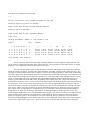
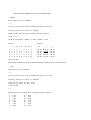
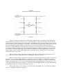
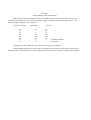
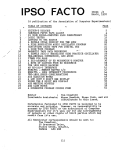
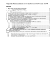
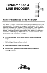
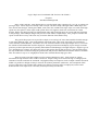
Logic Chip Tester User Manual SW Version 1.00 4/8/2012
Chapter 1
Introduction/Background
In the 1970’s and 80’s, many digital devices were designed using a number of 14, 16, 20, or perhaps 24pin logic chips. These chips were mostly 74LS or maybe 74S series chips, although 74HC CMOS chips were
also used in some designs. Metal gate CMOS, such as the 74C or 4000 series logic chips were used when high
speed was not required. These chips could operate from 12V supplies, which was convenient for certain
designs. While most designs today are implemented using chips featuring larger pin counts and more functions
in one package, some hobbyist designs may still use some of these simpler chips. Also, people involved in the
repair of older devices may want some way to test the function of this kind of chip.
The goal of this project was to provide a simple, low-cost logic IC tester that would be flexible enough
to test many different chips. (Sort of the modern equivalent of the “tube tester” that used to be in hardware
stores and other establishments) I decided to use a PC terminal emulator as the input/output device, to increase
the amount of information that could be displayed. Analog measurement and display of pin voltages seemed a
good way to detect pins that may be partially shorted due to ESD damage, but might still pass a “digital” type of
test. Displaying pin voltages also allows the user to interpret the data for him or herself. The current drawn by
the chip in idle state is measured using the ground lead, and provides additional information about its condition.
This also makes it easy to see roughly how much static current different chip types draw.
There are many tests that could be used to evaluate/characterize an IC. Input current or voltage
thresholds for high and low states could be measured. Output voltage level while sourcing or sinking specific
amounts of current could also be measured. Propagation delay from input or clock to output could be measured.
While it is possible to design circuitry to measure all of these parameters (and more), one assumption of this
project is that many non-working chips exhibit gross failures involving input or output pins, which can be
detected with a few simple tests. Of course, this may not always be the case.
Chapter 2
Setup
The logic chip tester was designed for use with either a stand-alone terminal, or a terminal emulation
program such as TeraTerm or HyperTerm running on a PC or Mac. Some chips require many columns of data
display, so being able to select a smaller font may come in handy to prevent the display from wrapping.
Serial settings are 8 data bits, no parity, and 1 stop bit. No hardware handshaking is needed, or
provided, so it should be disabled at the terminal/PC end.
My code uses “ANSI escape sequences” to invert the characters on the screen to white on black when
displaying errors. The terminal should support these for correct display. For many terminal programs, selecting
VT100 mode will insure that ANSI sequences are handled properly. If you see a lot of “0M”’s on your screen,
it’s not set to a mode that supports ANSI escape sequences.
The chip tester automatically detects the baud rate. After connecting the unit to a terminal (or a terminal
emulator), power up the unit. Next hit Enter on the terminal to send a carriage return. The tester uses this to
detect the baud rate and sets its rate to match. Supported rates are 300, 600, 1200, 2400, 4800, 9600, and 19.2K
baud. After the tester has set its baud rate, it will send the sign-on message:
Chip Tester (c) Tauntek, R. Grieb V0.54 January 12, 2012
Slave code version is: A2
Enter chip number to start
>
If you don’t see something similar to this after pressing Enter, power down the tester and try again. Note: The
sw version and date may change in the future if nec.
Chapter 3
Overview of Operation
Once the unit is powered up, and the sign-on prompt is displayed, you can enter the part number of a
chip to test. Any letter can be entered in either upper or lower case. Any of these is a valid entry:
ls00[Enter]
74LS00[Enter]
7400[Enter]
74hc00[Enter]
HC00[Enter]
S00[Enter]
74S00[Enter]
also:
4024[Enter]
4001[Enter]
40161[Enter]
etc.
Once you have entered a part number, hit Enter. The unit will tell you if it found that part in its
database:
> ls174
Found LS174 in our database
I have tried to support the most common chips, but there are too many to include them all. If the part is
supported, insert the chip in the test socket. Slide it down as far as it will go in the socket, away from the lever.
Pin one of the chip should be closest to the lever. All chips should be placed this way, regardless of the number
of pins. Finally, lower the lever to press the socket contacts against the pins of the chip.
Next hit T or t, and Enter, to test the chip:
> t
Vss pin current with only pulldowns enabled is ~10.7 mA
Checking inputs for shorts or leakage...
Input levels look OK with voltage dividers applied
Checking input connections...
Input levels look OK with pulldowns applied
Logic test:
Testing thresholds: VOHmin >= 3.30, VOLmax < 0.35
Inputs:
1
2
3
4
Clks:
Outputs:
3
4
6 11 13 14
1
9
2
5
7
10
12
15
H
L
H
H
L
H
H
H
H
L
H
H
H
H
H
L
P
P
P
I
H/3.51
L/0.21
H/3.52
L/0.24
L/0.22
H/3.51
H/3.52
L/0.24
H/3.51
L/0.21
H/3.51
L/0.24
L/0.21
H/3.50
H/3.52
L/0.23
H/3.51
L/0.21
H/3.52
L/0.23
L/0.21
H/3.51
H/3.52
L/0.23
L
H
H
H
H
L
H
H
L
H
H
H
Tests passed, chip looks OK
>
The current in the ground pin of the chip, with only pulldown resistors applied, is displayed first, and
can be used for comparison with other chips of the same type. The tester does not check the current. It simply
displays it. For CMOS chips, this current will be close to zero.
The unit will next apply resistor voltage dividers to all inputs and outputs (more on this later) and will
check the voltages on inputs. In general, the inputs should be at roughly 2.5V due to the voltage dividers. Any
input that is not close to this value will be reported. This test can reveal inputs that are either leaky or shorted to
one of the supply rails. Performing the input test first helps to prevent damage to the tester, as it keeps the tester
from trying to drive an input that is shorted to ground or 5V. If the input test passed, and a bipolar part is being
tested, a second input test will be performed with only pulldowns applied. This can detect pins that are not
making a good connection to the ZIF socket. Regardless of the results of this test, a logic test will then be
performed by applying a series of “test vectors” to the chip’s inputs and checking against expected responses on
the output pins. Test vectors consist of specific high or low values on input and possibly bi-dir pins, and can
also include single or multiple clock pulses for clocked parts. The vectors also include the expected output pin
logic levels. Inputs of the chip under test are driven with CMOS signal levels, which are close to 0V and 5V.
The voltage levels on output pins are measured using A to D converters, and compared against thresholds to
decide if they are high, low, or floating. Pin numbers are displayed at the top of the logic test results. Test
vector number, applied input levels, expected output states (H igh, L ow, F loat, or X (don’t care) and measured
output voltages are also displayed for each vector. Clock inputs are shown as either I, (inactive) P, (positive
pulse) or N (negative pulse). Any output that is not in the expected state on a particular vector will have its
measured voltage highlighted on the terminal when that vector is displayed. Some chips can be tested with just
a few vectors, while others require more. At the end of the test, an overall pass/fail result will be displayed.
Here is how the output from several bad chips looks:
> 74hc27
Found 74HC27 in our database
> t
Vss pin current with only pulldowns enabled is ~0.0 mA
Checking inputs for shorts or leakage...
Input levels look OK with voltage dividers applied
Logic test:
Testing thresholds: VOHmin >= 4.89, VOLmax < 0.10
Inputs:
1
2
3
4
5
Outputs:
1
2 13
3
4
5 11 10
9
12
6
8
L
H
L
L
H
L
L
H
L
H
L
H
L
L
H
L
L
H
L
H
L
L
L
H
H
L
L
L
H
H
H/4.95
L/0.02
L/0.02
L/0.02
L/0.02
H/4.95
L/4.95
L/0.02
L/0.02
L/0.02
H/4.95
L/0.02
L/0.02
L/0.02
L/0.02
L
L
L
H
H
L
H
L
L
H
L
L
H
L
H
Tests failed
Note: On the terminal screen, the underlined bold text would be inverse (white on black).
> ls32
Found LS32 in our database
> t
Vss pin current with only pulldowns enabled is ~2.4 mA
Checking inputs for shorts or leakage...
Input pin 10 looks too low: 1.00
Input pin 12 looks too low: 0.03
Tests failed
> v
Displaying pin voltages with voltage dividers applied
1
2
3
4
5
6
7
2.42
2.42
3.54
2.42
2.41
3.54
0.01
14
13
12
11
10
9
8
4.99
2.41
0.03
3.54
1.02
2.41
3.54
Chapter 4
The V Command
Another supported operation is displaying the voltage on every pin of the device. Hit V or v, then Enter,
to perform this operation. Voltage dividers are applied, which will tend to drive high levels into TTL chips, but
may be interpreted as either a high (1) or low (0) by CMOS chips. This test can show inputs that are shorted, or
outputs that are not in either a valid high or valid low state:
> hc154
Found HC154 in our database
> v
Displaying pin voltages with voltage dividers applied
1
2
3
4
5
6
7
8
9
10
11
12
------4.94
4.94
4.94
4.93
4.93
4.93
4.94
4.93
4.93
0.02
24
23
22
21
20
19
18
17
16
15
14
13
---------2.55
2.55
2.55
2.55
4.93
4.93
4.93
4.93
4.94
Note that in the above example, the voltage on some pins is not displayed. This is because there are
only a total of 20 ADC inputs available, 10 in each PIC chip. One channel is used to measure VSS current, so
19 pins can have their voltage measured. Since that is enough for most of the chips I wanted to support, I
decided not to add an analog mux chip, to keep the design simpler. As you can see, the pins that are analog
inputs are at the non-lever end of the ZIF socket. Pins that are not ADC inputs to the PIC chips are driven in the
same manner as the other pins, but can only be measured and displayed as either high or low.
Here is another example of output from the V command:
> 4069
Found 4069 in our database
> v
Displaying pin voltages with voltage dividers applied
1
2
3
4
5
6
7
2.44
2.86
2.43
2.62
2.42
3.03
0.01
14
13
12
11
10
9
8
4.99
2.42
3.09
2.43
2.77
2.42
2.85
Note that it is difficult to tell the outputs from the inputs using the displayed voltages. That is because
this particular part has low gain from input to output and since the inputs are being held at about VCC/2 by the
voltage dividers, the outputs are also at intermediate levels. Closer examination reveals that the pins that are not
quite at VCC/2 are 2, 4, 6, 8, 10, and 12. (plus the power pins) These are the output pins. Performing a logic
test on this same chip confirms that it is working normally:
> t
Vss pin current with only pulldowns enabled is ~0.0 mA
Checking inputs for shorts or leakage...
Input levels look OK with voltage dividers applied
Logic test:
Testing thresholds: VOHmin >= 4.34, VOLmax < 0.35
Inputs:
1
2
Outputs:
1
3
5
9 11 13
L
H
L
H
L
H
L
H
L
H
L
H
2
4
6
8
10
12
H/4.68
L/0.15
H/4.66
L/0.15
H/4.68
L/0.15
H/4.68
L/0.15
H/4.69
L/0.15
H/4.71
L/0.15
Tests passed, chip looks OK
>
Chapter 5
The D command
The D command also displays pin voltages, like the V command, but in this case only the pulldown
resistors are enabled. In general, TTL inputs will not be at ground with just a pulldown resistor applied as the
input circuitry pulls up on the pin. Most of the chips I tested have between 0.8 and 1.7 volts on inputs with just
the pulldown resistor connected. The purpose of this command was to detect input pins that are either opencircuited due to chip damage, or (more likely) not making a good connection to the ZIF socket due to some
crud or oxidation on the pin. I had several chips like this, which tested bad until I used an Exacto to scrape the
pins clean. With the D command, input pins that are not making a good connection should show a voltage of
around 0.1-0.15 volts. Note that output pins driving low will also show voltages in this area, so this test only
applies to input pins, and only for bipolar TTL parts, not CMOS chips.
Chapter 6
Leakage/Drive Measurement Approach
Figure 6.1
Figure 6.1 shows the voltage divider network that is applied to inputs and outputs during chip testing.
This same network is applied to all pins of 14, 16, and 20 pin devices. (Some pins on larger chips can only be
tested in a digital fashion without the resistor divider.) The diodes allow the resistors to effectively be removed
from the circuit by reverse-biasing them. This can be accomplished by bringing the PULLDNb signal to 5V and
the PULLUP signal to ground. In this case, the diodes are reverse-biased and the resistors are effectively
removed. A simpler aproach to testing logic chips would be to just use digital inputs to sense whether they are
in a high or low state. I wanted a way to detect inputs that might have leakage to ground or 5V, or outputs that
may not have the normal voltage swing. Since modern microcontrollers can drive digital logic levels or sense
analog voltages on the same pin, testing digital chips in an analog fashion is possible with no extra circuitry
except some resistors and diodes.
When the voltage divider is applied to an input pin, the expected voltage is approximately 5.0V/2 or
2.5V. Un-driven inputs are compared to this level and flagged if they are too far off.
When the voltage divider is applied to an output pin, it tends to pull the output towards 2.5V, which will
have more or less effect depending on the logic family being tested. For instance, a 74HC00 chip will have a
higher “1” level under these conditions than a 74C00 chip, as it has more output drive. When you enter a chip
number, the family (LS, HC, etc) is used to select different output voltage thresholds for testing the device. So
if you enter 74HC00 , the minimum passing “1” voltage level would be higher than for a 74C00. The thresholds
used during the logic test are displayed before the test is run.
During logic testing of open-collector or open-drain chips, PULLDNb is at 5V, removing the pulldown
resistors. The pullup resistors are still applied.
Chapter 7
Supported Power Pin Combinations
While many small-scale-integration logic IC’s in DIP packages use two corner pins for power and
ground, not all of them do. The tester has circuitry to apply 5V and Ground to specific pairs of pins. The
following eight combinations are supported:
Number of IC Pins
32
14
16
20
24
28
16
14
Ground Pin
16
7
8
10
12
14
8
10
+5V Pin
32
14
16
20
24
28
1
5
(CD4049, CD4050)
(7490,7493)
Chips that use other configurations for their power pins are not supported.
NPN and PNP transistors are used to apply 5V and ground to the selected pins, under control of the
microcontrollers. The transistors used were chosen for their low collector-to-emittor voltage drop (VCEsat).
Chapter 8
Chip Families
Many supported devices exist in either 7400, 74LS, 74HC, 74HCT, or 74C versions. The chip database
contains a flag for each family to indicate whether this part exists in that family. I realized early on that insuring
the correctness of this data would be time-consuming. Also, it’s not clear that this is really necessary. When
you enter a part number, the family is determined from the number entered, and this is used to select the voltage
thresholds for the output pins during the logic test. The family does not affect anything other than the logic
thresholds, so if you enter a non-existent part, such as an HCT266, (assuming that part does not exist), the same
test patterns will be used, so there’s little downside. The flags still exist in the database, but I have tried to err
on the side of assuming parts exist, to avoid disallowing a valid combination. In the event that you do see a
message something like “I found this part, but not in this family”, you can enter the part number in a different
way to move the part to a different family and test it anyway, possibly with different output thresholds.
One benefit of the family membership flags is that the sw can differentiate between chips that have a
different pinout in different families. Two examples of this are 74S51 vs 74LS51 and 74C86 vs 74HC86.
Luckily, for most chips the pinout is the same for different families.
Chapter 9
Design Overview
The chip tester uses two Microchip PIC18LF2420 microcontroller chips. One chip communicates with
the PC, contains all of the information about the chips that we can test, and also drives and measures half of the
pins on the device under test. The other chip drives and measures the rest of the pins, under control of the first
chip. The two chips communicate using an SPI serial interface.
A one ohm series resistor is used to measure the current in the ground pin of the device under test. The
voltage developed across this resistor is amplified by an operational ampilifer, and then fed into an ADC input
of a PIC chip. The one ohm value was chosen to minimize the voltage drop across the resistor, since this
reduces (slightly) the voltage applied to the device under test.