1
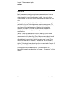
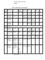
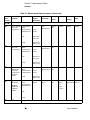
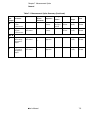
7
Measurement Optics
Chapter 7 Measurement Optics
General
General
Each laser measurement system’s measurement axis must have an
interferometer and a reflector. Machine design considerations
determine which type of interferometer is best. The choice of the
interferometer for each axis usually determines the reflector for that
axis.
This chapter describes the Agilent Technologies measurement optics
available for Agilent Technologies laser measurement systems. The
first part of this chapter presents material that should be useful to the
user of any of the interferometers. Following this introductory
material, the chapter is divided into subchapters that describe
individual interferometer types, including characteristics and
specifications.
Table 7-1 lists the measurement optics in order by Agilent Model
Number. It also: 1) identifies the subchapter in which each
measurement optic is described, 2) provides summary descriptions of
the measurement optics, and 3) lists the reflectors and Agilent
adjustable optics mounts with which the optics may be used. (The
mounts are described in Chapter 9, “Accessories,” of this manual.)
Agilent Technologies beam-directing optics are described in Chapter 6,
“Beam-Directing Optics,” of this manual.
Other Agilent optics that are neither 1) interferometers nor 2)
beam-directing optics are described in Chapter 9, “Accessories,” of this
manual.
7-2
User’s Manual
Chapter 7 Measurement Optics
General
Table 7-1. Measurement Optics Summary
Manual
Subchapter
Model Number
and Name
Application
Typical
System
Resolution
Beam
Separation
A
Agilent 10702A
Linear
Interferometer
General Purpose λ/64 (10 nm) 12.7 mm
(0.5 in)
B
Agilent 10705A
Single Beam
Interferometer
Low-mass
Limited space
C
Agilent 10706A
Plane Mirror
Interferometer
D
Agilent 10706B
High Stability
Plane Mirror
Interferometer
E, F
Reserved
G
Config-
Reflector
uration
Reflector
Weight
Mount
Used
Straightthrough or
Turned
Agilent
10703A
42 g
(1.5 oz)
Agilent
10711A
λ/64 (10 nm) Not
Applicable
(single beam)
Straightthrough or
Turned
Agilent
10704A
10.5 g
(0.4 oz)
Agilent
10710B
Plane Mirror
λ/128
(5 nm)
12.7 mm
(0.5 in)
Straightthrough or
Turned
Agilent
10724A or
user
supplied
50 g
(1.8 oz)
Agilent
10711A
Plane Mirror
λ/128
(5 nm)
12.7 mm
(0.5 in)
Straightthrough or
Turned
Agilent
10724A or
user
supplied
50 g
(1.8 oz)
Agilent
10711A
Agilent 10715A
Differential
Interferometer
High Accuracy
Plane Mirror
λ/128
(5 nm)
12.7 mm
(0.5 in)
Straightthrough or
Turned
Agilent
10724A or
user
supplied
50 g
(1.8 oz)
Agilent
10711A
H
Agilent 10716A
High Resolution
Interferometer
High Resolution
Plane Mirror
l/256
(2.5 nm)
12.7 mm
(0.5 in)
Straightthrough or
Turned
Agilent
10724A or
user
supplied
50 g
(1.8 oz)
Agilent
10711A
I
Agilent 10717A
Wavelength
Tracker
Wavelength-oflight
compensation
—
Not
Applicable
Not
Applicable
Built-in
Not
Applicable
none
J
Agilent 10719A
One-axis
Differential
Interferometer
One Linear
Plane Mirror
Measurement
(Differential)
See
StraightSpecifications through
only
custom
custom
custom
See
custom
custom
custom
λ/128
(5 nm)
or
One Angular
Measurement
K
Agilent 10721A
Two-axis
Differential
Interferometer
0.054 arcsec
(0.26 µrad)
Two Linear
Plane Mirror
Measurements
(Differential)
Straight-
Specifications through
only
Linear
λ/128
(5 nm)
Yaw
0.08 arcsec
(0.4 µrad)
User’s Manual
7-3
Chapter 7 Measurement Optics
General
Table 7-1. Measurement Optics Summary (Continued)
Manual
Subchapter
Model Number
and Name
L, M
Reserved
N
Agilent 10735A
Three-axis
Interferometer
N
N
O
Agilent 10736A
Three-axis
Interferometer
Application
3 Linear Plane
Mirror
Measurements
(Displacement,
Typical
System
Resolution
λ/128
(5 nm)
Yaw,
0.04 arcsec,
(0.2 µrad)
Pitch)
0.05 arcsec,
(0.24 µrad)
3 Linear Plane
Mirror
Measurements
(Displacement,
λ/128
(5 nm)
Yaw,
0.04 arcsec,
(0.2 µrad)
Pitch)
0.05 arcsec,
(0.24 µrad)
Beam
Separation
uration
Reflector
Weight
Mount
Used
Turned
Specifications only
custom
custom
custom
See
Turned
Specifications only
custom
custom
custom
See
Turned
Specifications only
custom
custom
custom
Plane
mirror
Customer
determined
Agilent
10711A
3 Linear Plane
Mirror
Measurements
( Displacement,
Pitch)
0.05 arcsec,
(0.24 µrad)
Agilent
10737L/R
3 Linear Plane
Mirror
Measurements
(Displacement,
See
See
Specs.
Specs.
Compact
Three-axis
Interferometers
Reflector
See
Agilent
10736A- 001
Three-axis
Interferometer
with Beam
Bender
λ/128
(5 nm)
Config-
Turned
only
or
cube
corners
Yaw,
Pitch)
P through U
Reserved
7-4
User’s Manual
Chapter 7 Measurement Optics
General
Table 7-1. Measurement Optics Summary (Continued)
Manual
Subchapter
Model Number
and Name
Application
A
Agilent 10766A
Linear
Interferometer
General Purpose λ/64 (10 nm) 11 mm
(0.43 in)
V
Agilent 10770A
Angular
Interferometer
High Accuracy
Plane Mirror
λ/64 (10 nm) 11 mm
(0.43 in)
W, X
Reserved
Y
Agilent 10774A
Short Range
Straightness
Optics
High Resolution
Plane Mirror
—
Agilent 10775A
Long Range
Straightness
Optics
High Resolution
Plane Mirror
—
Y
Typical
System
Resolution
User’s Manual
Beam
Separation
Config-
Reflector
uration
Reflector
Weight
Mount
Used
Straightthrough or
Turned
Agilent
10767A
224 g
(0.5 lb)
Agilent
10785A
—
Agilent
10771A
650 g
(1.5 lb)
Agilent
10785A
Not
Applicable
—
Included
800 g
(1.8 lb)
Agilent
10776A
Not
Applicable
—
Included
800 g
(1.8 lb)
Agilent
10776A
7-5
Chapter 7 Measurement Optics
Resolution
Resolution
The fundamental optical resolution for each interferometer type is
listed in Table 7-2. Using electronic resolution extension, the system
resolution is increased significantly. Depending on the system, an
additional resolution extension factor of 32 is usually available.
Table 7-2. Interferometer Resolutions
Interferometer Type
Fundamental Resolution
Linear
λ /2
0.316 micron (12.44 microinches)
Plane Mirror
λ /4
0.158 micron (6.32 microinches)
High Resolution Plane Mirror
λ /8
0.079 micron (3.12 microinches)
Range
The nominal optical measurement range for an Agilent laser
measurement system is usually 40 meters (130 feet) for the sum of all
axes. In calibrator systems, this range may be doubled with the
Agilent 5519A/B optional long range kit.
The 3 mm diameter beam of the Agilent 5517C-003 Laser Head allows
a maximum range of 10 meters (32 feet) for the sum of all axes.
Measurement Direction Sense
Direction sense depends on the relation of the optical frequencies in the
interferometer’s reference and measurement paths. This, in turn,
depends on: 1) the orientation of the laser head, 2) the effect of any
beam-bending optics in the path between the laser head and the
interferometer, and 3) the interferometer's configuration
(straight-through or turned).
For example, if: 1) f1 (the lower frequency from the laser head) is in the
measurement path (that is, the path going to the measurement
mirror), and 2) f2 (the higher frequency from the laser head) is in the
reference path (that is, the path going to the reference mirror), and 3)
the measurement optics are moving away from each other, the fringe
counts will be INCREASING.
7-6
User’s Manual
Chapter 7 Measurement Optics
Measurement Direction Sense
Interchanging f1 and f2 will reverse the direction sense, resulting in the
fringe counts DECREASING as measurement optics move away from
each other.
In this manual, “f1” and “f2” have been used to identify the two
frequency components of the laser beam. However, because the
components that left the laser head having horizontal and vertical
orientations can have the opposite orientations when they arrive at an
interferometer, “fA” and “fB” are used to identify the beam paths
through the interferometers. Figure 7-1 shows how two parallel beams,
derived from the same source, can have different polarization
orientations at interferometer inputs. An interferometer using one of
these beams will produce increasing counts as its measurement mirror
moves away from it; an identical interferometer, parallel to the first,
but using the second beam, will produce decreasing counts as its
measurement mirror moves away.
User’s Manual
7-7
Chapter 7 Measurement Optics
Measurement Direction Sense
VERTICAL AND HORIZONTAL POLARIZATION
Notes
1. Shaded ovals represent laser beam cross section (enlarged).
2. V = Vertical Polarization Component.
3. H = Horizontal Polarization Component.
4. fA and fB represent beam paths in Interferometer.
V
H
Beam Splitter
V
V
H
H
fB
H
Beam Bender
V
fA
Interferometer
V
fB
H
Interferometer
fA
Figure 7-1. Effect of beam-directing optics on laser beam polarization
orientations
7-8
User’s Manual
Chapter 7 Measurement Optics
Vibration Isolation
Vibration Isolation
Vibration of the optics along the laser beam can cause the fringe count
in the laser measurement system electronics to fluctuate rapidly.
Vibrations along this axis constitute real, measurable, displacements;
you will have to decide if these fluctuating measurements are
acceptable in your application. In extreme cases, however, the velocity
of the optics may momentarily exceed the velocity limitation of the
laser measurement system, causing an error.
When vibration occurs perpendicular to the beam, the beam signal
power can fluctuate. If this fluctuation is too great, insufficient beam
signal will arrive at the receivers, causing a “measurement signal
error.”
Loose mounting can cause the optics to move inappropriately during a
measurement, causing a measurement error or loss of beam power.
Elastic mounting can have the same effect as loose mounting. It can
also be responsible for a “sag” offset in the optics’ positions. If there is
vibration in the machine, an elastic mounting can transmit and
amplify the vibration to the attached optic, possibly causing more
errors. You should anticipate these effects and minimize them, if
necessary, during the laser measurement system design process.
Certain interferometers are inherently less susceptible to vibration
effects than others. This is particularly true of differential-style
interferometers such as the Agilent 10715A, Agilent 10719A, and
Agilent 10721A. The stability of these interferometers is due to the fact
that both their reference beams and their measurement beams travel
to external mirrors. Any motion of the interferometer itself that is
common to both beams will not appear as a measurement. Of course,
any vibration between the reference and mirrors will constitute real,
measurable, displacements.
Fasteners
Any optical component that fits an adjustable mount is supplied with
mounting screws to mount it on the appropriate adjustable mount.
User’s Manual
7-9
Chapter 7 Measurement Optics
Vacuum Applications
Vacuum Applications
Many of the optical components of the laser measurement system have
vacuum options, which are compatible with vacuum environments.
Contact Agilent Call Center for information (telephone numbers of
various call centers are listed on the “Service and Support” page at the
back of this manual). Typically, these components have housings made
of stainless steel and optical elements attached to the housings using a
lower volatility (vacuum-grade) adhesive. See the specifications for a
list of materials used in the optics.
Use Through Window
If the laser beam has to go through a window (for example into a
vacuum chamber) the window must meet the following requirements:
•
A minimum window aperture of 25.4 mm (1 inch) with a minimum
thickness of 8 mm (0.3 inch). If a larger window is used, it must be
proportionally thicker to assure no distortion in the window when
under differential pressures.
•
Transmitted wavefront distortion less than λ/10 (peak-valley,
single-pass) over a 23 mm (0.9 inch) diameter.
•
Parallelism of faces less than ±2 arc-minutes, to reduce beam
steering.
•
Surface quality 60-40 or better, per Mil-0-13830.
•
The window must be strain-free.
Differential Measurements with
Interferometers
Several interferometers have the capability to make differential
measurements. A differential, measurement is one in which both the
reference beam and the measurement beam travel to external mirrors
outside the interferometer housing. This allows measurement of the
relative positions of the two external mirrors, either or both of which
may be moving. Viewed another way, this allows measuring the motion
of one reflector relative to a reference datum elsewhere in the machine,
external to the interferometer itself. This is unlike the typical
interferometer configuration because usually the reference beam path
length does not change; in differential configurations, it can.
7-10
User’s Manual
Chapter 7 Measurement Optics
Differential Measurements with Interferometers
One useful example of a differential measurement in a lithography
application is for measuring the motion of the X-Y stage relative to the
optical column. The Agilent 10719A One-Axis Differential
Interferometer and the Agilent 10721A Two-Axis Differential
Interferometer are ideally suited to this type of measurement, because
they provide parallel reference and measurement paths which are
offset vertically by 19 mm (0.750 inch). For such an application, a usersupplied reference plane mirror is required in addition to the
measurement reflector on the X-Y stage.
Differential measurements that can be made using an Agilent 10719A
interferometer are shown in Figure 7J-2. Differential measurements
that can be made using an Agilent 10721A interferometer are shown in
Figure 7K-2.
The Agilent 10715A Differential Interferometer, instead of having an
offset spacing as in the Agilent 10719A or Agilent 10721A
interferometers, permits the reference beams and the measurement
beams to be aligned essentially coaxially. A specially-shaped reference
plane mirror (shown in Figure 7G-7) is supplied with the
Agilent 10715A. For more information about the Agilent 10715A, see
subchapter 7G of this manual.
Customized differential configurations are possible with several other
interferometers. However, considerable care should be exercised
during design and layout to avoid introduction of alignment errors,
thermal or mechanical instabilities, and potential deadpath problems.
When making differential measurements, both reflectors (reference
and measurement) should be of the same type (cube corner or plane
mirror); this minimizes thermal drift problems with ambient
temperature changes.
To use the Agilent 10702A, Agilent 10705A, or Agilent 10766A in a
differential configuration, the reference cube corner can simply be
detached from the interferometer housing and attached to the
reference surface of interest. This is shown in Figure 7A-7 in the
Linear Interferometers subchapter (subchapter 7A) of this manual. Be
aware that all installation and alignment requirements for the
measurement reflector now apply also to the reference reflector.
To use the Agilent 10706A or Agilent 10706B interferometer in a
differential configuration, a plane mirror is recommended as the
reference reflector. Simply replace the reference cube corner (or highstability adapter) with the Agilent 10722A Plane Mirror Converter and
attach the reference plane mirror to the reference surface of interest.
This is shown in Figure 7C-4 in the plane mirror subchapter
(subchapter 7C) of this manual. Again, install and align the reference
reflector the same as you would the measurement reflector.
User’s Manual
7-11
Chapter 7 Measurement Optics
Moving Interferometer Instead of Reflector
Moving Interferometer Instead of Reflector
When moving the interferometer instead of the measurement reflector
is required, the Agilent 10702A-001 (or Agilent 10766A) should be
used. In practice, for alignment reasons, these are the only
interferometers (except the straightness interferometers) that can be
moved while making measurements. For a detailed explanation of why
this option is required, see Figure 7A-2 in the Linear Interferometers
subchapter (subchapter 7A) of this manual.
Product specifications and descriptions in this
document subject to change without notice.
Copyright (C) 2002 Agilent Technologies
Printed in U.S.A. 07/02
This is a chapter from the manual titled:
Laser and Optics User's Manual
For complete manual, order:
Paper version: p/n 05517-90045
CD version: p/n 05517-90063
This chapter is p/n 05517-90107
7-12
User’s Manual