1
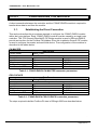
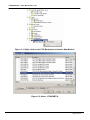
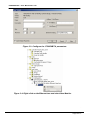
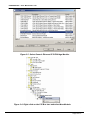
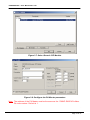
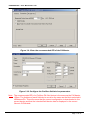
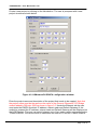
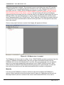
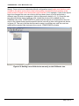
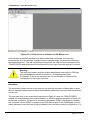
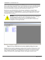
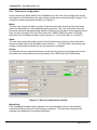
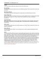
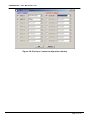
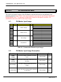
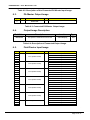
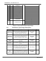
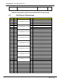
Allen-Bradley Logix
to Profibus PA interface
USER MANUAL
Rev 5.04 – January 2008
1788HP-EN2PA - User Manual Rev 5.03
Table of Contents
Chapter 1
Chapter 2
Chapter 3
Chapter 4
Chapter 5
Chapter 6
Chapter 7
Appendix A
Introduction.................................................................................................................3
Module Operation & Installation..............................................................................4
Configuring the Module ............................................................................................6
COnfiguring field devices .......................................................................................13
FDT / DTM ................................................................................................................22
I/O Address Map......................................................................................................23
Specifications ...........................................................................................................29
module status ...........................................................................................................31
.
Page 2 of 31
1788HP-EN2PA - User Manual Rev 5.03
CHAPTER 1
INTRODUCTION
The 1788HP-EN2PA is a Profibus PA Master which connects an Allen-Bradley Logix
Controller (via Ethernet/IP) to various Profibus PA field devices.
The user can configure each 1788HP-EN2PA to exchange cyclic data with up to 16
Profibus PA Field Devices using RSLogix 5000 and HSNetworxPA.
The module can also be used to exchange acyclic data with each field device using FDTDTM technology. Each field device can be configured in detail by using Hiprom
Technologies’ DTM package and a FDT frame (e.g. FieldCare).
This document serves to describe the functionality, installation, configuration and operation
of the module.
.
Page 3 of 31
1788HP-EN2PA - User Manual Rev 5.03
MODULE OPERATION & INSTALLATION
CHAPTER 2
The 1788HP-EN2PA module is designed to operate within the Allen-Bradley Logix
controller system using CIP Ethernet. All power required for the module’s operation must
be derived from an external 24V power supply. Please refer to electrical specifications for
current consumption.
LCD Display
PA Bus
24V Power supply
RJ45 Ethernet
Figure 2.1: 1788HP-EN2PA Layout
PABUS:
24V PWR:
Connector Pin 1 -> PA “+” terminal, Connector Pin 3 -> PA – terminal. Pin 4
is used for the cable shield.
Connector Pin 1 -> “+” terminal, Connector Pin 2 -> “-“ terminal
.
Page 4 of 31
1788HP-EN2PA - User Manual Rev 5.03
RJ45:
Connector Pin 1 & 3 and Connector Pin 2 & 4 are twisted pairs as shown
below in figure 2.2.
Figure 2.2: Ethernet cable layout
The current status of the module is conveyed to the user by means of the LCD Display.
Appendix A details the various states of the LCD Display messages.
The following information is available and can be sent by the user directly across the
backplane by means of a scheduled connection:
• 8 Input process variables (PVs) and 8 Output PVs from up to of 16 Profibus PA field
devices.
• Diagnostics from the 1788HP-EN2PA module
• Extended diagnostics of each Profibus PA field device
•
The positive terminal of the 1788HP-EN2PA’s Profibus PA connector (as shown in figure
2.1) must be connected to the positive terminal of all connected Profibus PA instruments (if
standard Profibus PA cable is used the standard is red – positive, green – negative).
Warning:
If the positive and negative terminal of the EN2PA is not correctly connected
to the positive and negative terminals of the respected Profibus PA field
devices it may cause permanent damage to the connected instruments.
.
Page 5 of 31
1788HP-EN2PA - User Manual Rev 5.03
CONFIGURING THE MODULE
CHAPTER 3
A direct connection between the controller and the 1788HP-EN2PA module is required to
transfer drive data to and from the module .
3.1.
Establishing the Direct Connection
This section describes the procedures required to configure the 1788HP-EN2PA module
within the Logix platform. Each 1788HP-EN2PA module must be owned by a single Logix
controller. The 1756 Generic EtherNet/IP CIP Bridge module is used in RSLogix 5000 to
provide an interface for the Profibus PA fieldbus. Once this is added a Generic CIP module
is used to configure the master and each field device. The configuration of the modules is
described in the tables below.
PA MASTER
CommFormat
Description
Input
Output
Configuration
Recommended RPI
Data Format
Data – DINT
Connection parameters
Instance
65
66
68
150.0ms
Size
4 (32 Bit)
1 (32 Bit)
4 (8 Bit)
Table 3.1: 1788HP-EN2PA PA MASTER connection parameters.
FIELD DEVICE
CommFormat
Description
Input
Output
Configuration
Recommended RPI
Data Format
Data – DINT
Connection parameters
Instance
65
66
68
150.0ms
Size
26 (32 Bit)
10 (32 Bit)
50 (8 Bit)
Table 3.2: 1788HP-EN2PA FIELD DEVICE connection parameters.
The steps required to build a Profibus PA tree in RSLogix 5000 are described below.
.
Page 6 of 31
1788HP-EN2PA - User Manual Rev 5.03
Figure 3.1: Right-click on the 1756 Backplane and select New Module.
Figure 3.2: Select 1756-ENBT/A.
.
Page 7 of 31
1788HP-EN2PA - User Manual Rev 5.03
Figure 3.3: Configure the 1756-ENBT/A parameters.
Figure 3.4: Right-click on the Ethernet tree and select New Module.
.
Page 8 of 31
1788HP-EN2PA - User Manual Rev 5.03
Figure 3.5: Select Generic Ethernet/IP CIP Bridge Module .
Figure 3.6: Right-click on the CIP Bus tree and select New Module.
.
Page 9 of 31
1788HP-EN2PA - User Manual Rev 5.03
Figure 3.7: Select Generic CIP Module.
Figure 3.8: Configure the PA Master parameters.
Note: The address of the PA Master must be the same as the 1788HP-EN2PA Profibus
PA node number. Default is 1.
.
Page 10 of 31
1788HP-EN2PA - User Manual Rev 5.03
Figure 3.9: Enter the recommended RPI of the PA Master
Figure 3.10: Configure the Profibus field device parameters.
Note: The recommended RPI of a Profibus PA field device is the same as the PA Master,
150ms. The Address of each field device must be the same as the block selected in
HSNetworxPA. This will ensure that the correct configuration is downloaded to the
correct device and that the intended field device data is displayed in the correct
Generic CIP Module.
.
Page 11 of 31
1788HP-EN2PA - User Manual Rev 5.03
The connection between the controller and 1788HP-EN2PA can fail if:
•
•
•
The specified size of the Input, Output, or Configuration size is incorrect
The assembly instance of the input, Output and Configuration is incorrect
An RPI is not set to recommended or reasonable interval.
.
Page 12 of 31
1788HP-EN2PA - User Manual Rev 5.03
CHAPTER 4
CONFIGURING FIELD DEVICES
HSNetworxPA is the software that will be used to create the configuration that will be
stored in the Logix Controller that is used to access cyclic data of each Field Device. It is
supplied with the module and must be installed on any personal computer running MS
Windows XP.
4.1.
HSNetworxPA
The following will describe how HSNetworxPA will be used to scan the bus, view an
instrument’s diagnostics and configuration, use GSD files, change EN2PA parameters and
downloading configuration data to the Logix Controller and 1788HP-EN2PA module.
NOTE:
If the user wants to use a certain instrument, that instrument’s GSD file must
be added to the GSD library to be recognized by HSNetworxPA. The user
cannot add a device without the GSD file. This is done by selecting Import
GSD Files under the GSD Wizard tab in HSNetworxPA. Select a GSD file
and click open.
4.1.1 Program startup
When the user starts HSNetworxPA a blank screen will be given as shown below.
Figure 4.1: HSNetworxPA startup screen.
.
Page 13 of 31
1788HP-EN2PA - User Manual Rev 5.03
Create a new project by clicking on the New button. The user is prompted with a new
project window as shown below.
Figure 4.2: HSNetworxPA EN2PA configuration window.
Enter the project name and description of the project that needs to be created. Note that
the project name must be the same as the name of the Generic Ethernet/IP CIP Bridge
module added in RSLogix 5000 as shown in figure 3.5. Under the Ethernet tab the user
must enter the EN2PA module’s IP address, subnet mask and Default Gateway (if the
module is powered the IP address, subnet mask and Default Gateway will be displayed on
the LCD Display). The user can select between one of two options when connecting to the
1788HP-EN2PA. The Direct choice is used when the user’s PC and the 1788HP-EN2PA
.
Page 14 of 31
1788HP-EN2PA - User Manual Rev 5.03
are both on the same network. The extended route is used when the user’s PC and the
1788HP-EN2PA are on different Ethernet networks (if the user has the LAN network on
one ENBT and the 1788HP-EN2PA Ethernet network on another ENBT. Note that this is
the preferred way of connecting the 1788HP-EN2PA, because it keeps the local network
from increasing traffic on the control network). On the Profibus PA tab, the PA Master
address has to be selected (this has to be the same as the address selected by the user in
RSLogix 5000), the max address that is used for when scanning the bus and the retries
when requesting data from a Field Device. The IP address of the Ethernet module that will
connect to the Logix controller and in which slot the processor is in that specific rack also
has to be entered.
Once a new project has been created, the display will appear as follows :
Figure 4.3: PA Master tree is created.
The PAMaster will show that it is offline. If the 1788HP-EN2PA module is powered, has the
correct IP address and subnet mask, the user can press the Refresh button and the
PAMaster will connect and display that it is o nline. Once it is online the user can expand
the tree to view certain parameters and settings of the 1788HP-EN2PA module. Next
either add the Profibus PA field devices that are going to be used manually or scan the
bus and the field devices will be added automatically with a default configuration.
Manually
Left click on the PAMaster to select it and then right click to display the PAMaster’s
options. Select add device from the list as shown in figure 4.4. Next select a device from
the drop-down list (the list consists of the various instruments GSD files in the user’s
.
Page 15 of 31
1788HP-EN2PA - User Manual Rev 5.03
library). Once a device is selected a default configuration is set (make sure that the node
number is the same as the device that is being setup and that the block number is the
same as that of needs to be used in the Logix controller). For example, if one of the inputs
has to be changed the user can click on the drop down menu of a slot and select a
different input if the device supports it (this is discussed in detail in 4.1.2). Once the user
has selected all the desired settings click ok and the device will be added into the
PAMaster tree. If the 1788HP-EN2PA is online and the device is connected the user can
click on the refresh button and the specific device icon will go from red to green as shown
in figure 4.5. The rest of all the devices can be setup in a similar way until the user has
added all the needed field devices to the current 1788HP-EN2PA module.
Figure 4.4: Adding a new field device manually to the PA Master tree.
.
Page 16 of 31
1788HP-EN2PA - User Manual Rev 5.03
Figure 4.5: A field device is added to the PA Master tree.
Once all the needed field devices have been added and configured, the user can
download the all of the devices’ configurations to selected Logix Controller by clicking on
the download button. This will configure/reconfigure all the field devices connected to the
1788HP-EN2PA and download the configuration to the Logix Controller where it is stored.
Warning:
The user must ensure that the module has already been setup in RSLogix
and downloaded as shown in section 3.1 Establishing the Direct
Connection. If this is not done the user will not be able to download the
configuration to the Logix Controller.
Automatic
The automatic setup is similar to the manual one with the exception of being able to scan
the bus and the instruments are added automatically rather than having to add the devices
one by one.
The user can click on the scan button as shown in figure 4.6 and the 1788HP-EN2PA
module will start scanning from node address 1 to the max address (selected in figure 4.2.)
for devices on the bus. If a device is received it will take its IDENT (identification) number
and compare it to the IDENT numbers of the GSD files located in the GSD library. Once a
match has been found the device will be added to the tree with a default configuration. If a
.
Page 17 of 31
1788HP-EN2PA - User Manual Rev 5.03
device is found but there is no match in the GSD library the user will be prompted with the
device node number and IDENT number. Once all devices have been successfully added
the tree will be finished. The user can configure each device by right clicking on that
device and selecting the configure tab (this is discussed in detail in 4.1.2).
Next the user can download the all of the devices’ configuration to selected Logix
Controller by clicking on the download button. This will configure/reconfigure all the field
devices connected to the 1788HP-EN2PA and download the configuration to the Logix
Controller where it is stored.
Warning:
The user must ensure that the module has already been setup in RSLogix
and downloaded as shown in section 3.1 Establishing the Direct
Connection. If this is not done the user will not be able to download the
configuration to the Logix Controller.
Figure 4.6: A set of field devices have been added by doing a bus scan.
Once the devices on the bus have been configured the IO modules (field devices) on the
CIP Bus under the Ethernet/IP CIP Bridge Module will establish a connection and cyclic
data exchange will begin. The data of the devices can be seen in the input and output
images of the various IO modules added. Section 6 will explain how this is done.
.
Page 18 of 31
1788HP-EN2PA - User Manual Rev 5.03
4.1.2 Field device configuration
Once a device has been added to the PAMaster tree, the user must configure the inputs
and outputs of the field device by right clicking on the device and selecting Configure. The
configure screen is presented as shown in Figure 4.7.
Block:
The user can change the block number of the field device by clicking on the drop down
menu and selecting any of the allowable block numbers. The user must ensure that the
block that has been assigned to that specific field device is the same as the address that is
used for the IO module in the CIP Bus under the 1788HP-EN2PA module in RSLogix.
Note that if the PA Master profibus node number is 1, it will not be able to use block 1.
Node:
The user can change the node number of the field device by clicking on the drop down
menu and select any of the allowable node numbers 1 - 126. Note that if the wrong node
number is selected the field device will not respond or configure.
Device:
If a different device is needed the same can be done by clicking on the drop down menu
and select any of the listed devices (according to the GSD files in the GSD library).
Figure 4.7: Device configuration window.
Watch Dog:
If the Watchdog Enabled tickbox has been set, the watchdog value is automatically
calculated using the amount of field devices o n the bus. The user can change this by
entering new parameters and pressing Refresh.
.
Page 19 of 31
1788HP-EN2PA - User Manual Rev 5.03
TSDR:
This is the fastest valid slave response set to the field device.
Group Ident:
The user can set certain field devices into different groups. This is reserved for future use
(default 0).
WatchDog Enable:
This tickbox enable the watchdog and corresponds to the Watch Dog time value.
Freeze Required:
When freeze mode is activated, the user can send a global control message which keeps
the inputs of the slave in a “frozen” state. This is reserved for future use (default
unselected).
Sync Required:
When sync mode is activated, the user can send a global control message which keeps
the outputs of the slave in a momentary state. This is reserved for future use (default
unselected).
Slave Lock:
The user can lock the slave for another master on the bus. This is reserved for future use
(default unselected).
Slave Unlock:
The user selects this tickbox to not lock the slave for other masters which allows cyclic
data exchange.
Slot x:
The user can select different inputs, outputs and inputs/outputs for the different allowable
slots of the slave. Thus using the user manual supplied with the field device, the user can
select which input/output to use in which slot and in what format the input/output must be
presented in the Controller. The user can press the dropdown menu and select the
process variable type and use the second dropdown menu to select how the message is
compiled. Some field devices have been assigned slots that support multiple inputs and
outputs. For this the user has to select the amount of inputs and outputs and in what
formats they are presented in the Controller. This is shown below in figure 4.8. The
1788HP-EN2PA supports 8 inputs and 8 outputs per field device. Note that some field
devices support multiple inputs and/or outputs on a single slot. In this case the user must
select the “Manual Config” tickbox and manually enter the amount and format of the
specific inputs and/or outputs.
.
Page 20 of 31
1788HP-EN2PA - User Manual Rev 5.03
Figure 4.8: Slot input / output configuration window.
.
Page 21 of 31
1788HP-EN2PA - User Manual Rev 5.03
CHAPTER 5
FDT / DTM
The 1788HP-EN2PA supports FDT (Field Device Type) / DTM (Device Type Manager)
technology. This allows the user to get all the acyclic data benefits from each field device
that has a DTM. The user is able to sit in his/her office and do detailed configuration,
calibration, audit trails, asset management of all field devices and many other features.
The user just needs to install and add the supplied 1788HP-EN2PA DTM in the FDT frame
(eg. Fieldcare). All the instruments connected to the 1788HP-EN2PA can then be
accessed from within the FDT frame.
.
Page 22 of 31
1788HP-EN2PA - User Manual Rev 5.03
I/O ADDRESS MAP
CHAPTER 6
The input and output images of the PA Master and the field devices are defined in the
following sections. Note “XXX” is the name chosen by the user for the Generic Ethernet/IP
Bridge Module and “?” is the block number that is used for the specific module. It is
advised the user use a UDT for the input image.
6.1.
PA Master Input Image
Byte
Point
Bit
0
1
2
3
4
5
6
7
8
9
10
11
12
13
14
15
PV
Point Description
Byte
Byte
Byte
Byte
Byte
Byte
Byte
Byte
Byte
Byte
Byte
Byte
Byte
Byte
Byte
Byte
PABus Voltage
PABus Current
Ext Voltage
Temperature
0
1
2
3
0
1
2
3
0
1
2
3
0
1
2
3
Table 6.1: Connected PA Master Input Image.
6.2.
PA Master Input Image Description
Field/Value
Description
Location
Type
PABus
Voltage
This is the voltage measured on the bus
itself.
XXX:?:I.Data[0]
REAL
PABus
Current
This is the current drawn measured on the
bus itself.
XXX:?:I.Data[1]
REAL
Ext Voltage
This is the voltage measured from the
supply.
XXX:?:I.Data[2]
REAL
Temperature
This is the internal temperature measured
on the board.
XXX:?:I.Data[3]
REAL
.
Page 23 of 31
1788HP-EN2PA - User Manual Rev 5.03
Table 6.2: Description of the Connected PA Master Input Image.
6.3.
PA Master Output Image
Byte
Bit
0
Point
PV
Point Description
Reserved
Table 6.3: Connected PA Master Output Image .
6.4.
Output Image Description
Field/Value
Description
Location
Type
Reserved
This space is reserved for future use.
XXX:O.Data[0-3]
DINT
Table 6.4: Description of Connected Output Image.
6.5.
Byte
0
1
2
3
4
5
6
7
8
9
10
11
12
13
14
15
16
17
18
19
20
21
22
23
24
25
26
Field Device Input Image
Bit
Point
PV1 (Real Format)
PV2 (Real Format)
PV3 (Real Format)
PV4 (Real Format)
PV5 (Real Format)
PV6 (Real Format)
PV7 (Real Format)
PV
Point Description
Byte 3
Byte 2
Byte 1
Byte 0
Byte 3
Byte 2
Byte 1
Byte 0
Byte 3
Byte 2
Byte 1
Byte 0
Byte 3
Byte 2
Byte 1
Byte 0
Byte 3
Byte 2
Byte 1
Byte 0
Byte 3
Byte 2
Byte 1
Byte 0
Byte 3
Byte 2
Byte 1
.
Page 24 of 31
1788HP-EN2PA - User Manual Rev 5.03
27
28
29
30
31
32
33
34
35
36
37
38
39
40
41
42
43
44
45
46
47
48
49
50
51
52
53
54
55
56
57
58
59
60
61
62
63
64
65
66
67
68
69
70
71
72
72
72
PV8 (Real Format)
PV1 (DINT Format)
PV2 (DINT Format)
PV3 (DINT Format)
PV4 (DINT Format)
PV5 (DINT Format)
PV6 (DINT Format)
PV7 (DINT Format)
PV8 (DINT Format)
0
1
2
Byte
Byte
Byte
Byte
Byte
Byte
Byte
Byte
Byte
Byte
Byte
Byte
Byte
Byte
Byte
Byte
Byte
Byte
Byte
Byte
Byte
Byte
Byte
Byte
Byte
Byte
Byte
Byte
Byte
Byte
Byte
Byte
Byte
Byte
Byte
Byte
Byte
0
3
2
1
0
0
1
2
3
0
1
2
3
0
1
2
3
0
1
2
3
0
1
2
3
0
1
2
3
0
1
2
3
0
1
2
3
PV1 Status
PV2 Status
PV3 Status
PV4 Status
PV5 Status
PV6 Status
PV7 Status
PV8 Status
Online
Ready
Config Fault
.
Page 25 of 31
1788HP-EN2PA - User Manual Rev 5.03
72
72
72
72
72
72
72
72
72
72
72
72
72
73
74
3
4
5
6
7
8
9
10
11
12
13
14
15
Ext Diag Avl
Diag Support
Invalid Slave Response
Parameter Fault
Master Lock
Parameter Req
Station Diag
WatchDog
Freeze Mode
Sync Mode
Ext Diag Overflow
Reserved
Reserved
Ident Number
75 99
Ext Diagnostics [6]
Byte
Byte
Byte
Byte
Byte
Byte
0
1
0
1
2
3
Table 6.5: Connected Field Device Input Image.
6.6.
Field Device Input Image Description
Field/Value
Description
Location
Type
Device PV
(Real Format)
This is the process values received from
each channel of the field device as
previously configured in real format.
XXX:?:I.Data[0] Data[7]
REAL
Device PV
(DINT Format)
This is the process values received from
each channel of the field device as
previously configured in DINT format.
XXX:?:I.Data[8] Data[15]
DINT
Device PV
Status
This is the status of the PV received from
each channel of the field device.(When
applicable)
XXX:?:I.Data[16] Data[17]
SINT[8]
Profibus
diagnostics
The standard Profibus PA diagnostics are
supplied
XXX:?:I.Data[18]
INT
Ident Number
The identity number of each field device
type is given in this field. Thus the same
type of field device from the same vendor
will have the same Ident number
XXX:?:I.Data[18]
INT
XXX:?:I.Data[19] Data[25]
BIT
Ext
Diagnostics
The extended diagnostics of each device
is given. The user can use the GSD file of
the specific device to make sense of each
field device extended diagnostics. Note
.
Page 26 of 31
1788HP-EN2PA - User Manual Rev 5.03
that it is bit aligned.
Table 6.6: Description of the Connected Field Device Input Image.
6.7.
Byte
0
1
2
3
4
5
6
7
8
9
10
11
12
13
14
15
16
17
18
19
20
21
22
23
24
25
26
27
28
29
30
31
32
33
34
35
36
37
38
39
Field Device Output Image
Bit
Point
PV1 (DINT/REAL Format)
PV2 (DINT/REAL Format)
PV3 (DINT/REAL Format)
PV4 (DINT/REAL Format)
PV5 (DINT/REAL Format)
PV6 (DINT/REAL Format)
PV7 (DINT/REAL Format)
PV8 (DINT/REAL Format)
PV1
PV2
PV3
PV4
PV5
PV6
PV7
PV8
PV
Point Description
Byte 0
Byte 1
Byte 2
Byte 3
Byte 0
Byte 1
Byte 2
Byte 3
Byte 0
Byte 1
Byte 2
Byte 3
Byte 0
Byte 1
Byte 2
Byte 3
Byte 0
Byte 1
Byte 2
Byte 3
Byte 0
Byte 1
Byte 2
Byte 3
Byte 0
Byte 1
Byte 2
Byte 3
Byte 0
Byte 1
Byte 2
Byte 3
Status
Status
Status
Status
Status
Status
Status
Status
.
Page 27 of 31
1788HP-EN2PA - User Manual Rev 5.03
Table 6.7: Connected Field Device Output Image.
6.8.
Field Device Output Image Description
Field/Value
Description
Location
Type
Device PV
(Real/DINT
Format)
This is the process values send to each
channel of the field device in real format
or DINT format depending on how it
was configured.
XXX:?:O.Data[0] Data[7]
REAL/DINT
Device PV
Status
This is the status of the PV sent for
each channel of the field device.(When
applicable)
XXX:?:O.Data[8]
SINT[8]
Table 6.8: Description of Connected Field Device Output Image.
.
Page 28 of 31
1788HP-EN2PA - User Manual Rev 5.03
CHAPTER 7
7.1.
SPECIFICATIONS
Electrical
Input voltage range:
Current @ 24V (no instruments attached):
PA Bus supply current (@ 24V)
7.2.
9 – 32V
180mA
500mA
Mechanical
Dimensions
No connectors : 170mm x 179mm x 59 mm (w x h x d )
With connectors : 170mm x 242mm x 59 mm (w x h x d )
.
Page 29 of 31
1788HP-EN2PA - User Manual Rev 5.03
Figure 8.1: Physical dimensions ( with connectors plugged in)
.
Page 30 of 31
1788HP-EN2PA - User Manual Rev 5.03
APPENDIX A
MODULE STATUS
The following sections describe the status indicators of the module:
A.1. LCD Display
Top 16 characters
EN2PA v5.05
PABus: 22.7V
PABus: 130mA
Ext: 23.2V
Temp: 38.00C
196.135.145.236
255.255.255.0
196.135.145.1
Bottom 16 characters
Not Configured
Unkown
B00 N13 OL> CF>
B00 N13 OL> CFx
B00 N13 OLx CFx
Revision number of the current module
PA Bus voltage
PA Bus current
External supply voltage
PCB temperature
IP Address
Subnet Mask
Default Gateway
No field devices have been configured
There is no input data or the module has lost
Ethernet communication to the controller
Block 0 Node 13 is online and configured for
cyclic data
Block 0 Node 13 is online but not configured for
cyclic data
Block 0 Node 13 is not online
.
Page 31 of 31