1
ANTTI KAMPPI
LIBRARY MANAGEMENT IMPLEMENTATION ON KACTUS2 IPXACT TOOL
Master's thesis
Examiner: Prof. Timo D. Hämäläinen, Dr. Erno
Salminen
Examiner and topic approved by the Faculty
Council of the Faculty of Computing and
Electrical Engineering on 7. November 2012.
TIIVISTELMÄ
TAMPEREEN TEKNILLINEN YLIOPISTO
Tietotekniikan koulutusohjelma
ANTTI KAMPPI: Kirjastonhallinnan toteutus Kactus2 IP-XACT työkalussa
Diplomityö, 112 sivua, 18 liitesivua
Joulukuu 2012
Pääaine: Sulautetut järjestelmät
Tarkastajat: Prof. Timo D. Hämäläinen ja TkT Erno Salminen
Avainsanat: Järjestelmäpiiri, IP-lohko, kirjastonhallinta, metadata, IP-XACT
Sulautettujen järjestelmien koko ja monimutkaisuus ovat viime vuosina kasvaneet
kiihtyvällä tahdilla. Siksi suunnittelun tuottavuutta täytyy tehostaa, johon on pyritty
mm. käyttämällä uudelleenkäytettäviä logiikkakomponentteja. Uudelleenkäytön
tehostaminen vaatii uusia suunnittelutyökaluja ja metodeja. IP-XACT on XMLpohjainen
metadata
standardi,
jolla
kuvataan
uudelleenkäytettäviä
logiikkakomponentteja, eli IP-lohkoja, työkalu- toteutus- ja toimittajaneutraalilla
tavalla. Ongelmana IP-XACT:in yleistymisessä on ollut työkalujen tuki. Saatavilla ei
ole aiemmin ollut vapaan lähdekoodin suunnittelutyökaluja ja kaupalliset vaihtoehdot
ovat kalliita, mikä rajoittaa pienten ja keskisuurten yritysten mahdollisuuksia ottaa IPXACT käyttöön.
Tässä diplomityössä esitellään avoimen lähdekoodin Kactus2 työkalu IP-XACTpohjaiseen suunnitteluun. Työn aiheena on työkalun kirjastonhallinta- ja IPpaketointimoduulit, joiden avulla IP-lohkoille voidaan luoda metadata-kuvaukset ja
hallinnoida lohkoja automatisoidusti. Diplomityössä esitellään muutamia lisäyksiä,
jotka laajentavat alkuperäistä standardia myös tuotetiedon hallintaan. Työssä sekä
suunniteltiin että toteutettiin kirjastonhallinnan ja paketoinnin vaatimat luokat ja
käyttöliittymänäkymät. Toteutuksessa käytettiin C++ ohjelmointikieltä ja
ohjelmistokehyksenä käytettiin Qt:n avoimen lähdekoodin versiota 4.8.3.
Kehitysympäristönä toimi Microsoftin Visual Studio 2008, johon oli asennettu Qt
lisäosa. Qt mahdollistaa järjestelmäriippumattoman koodin kirjoittamisen, joten
Kactus2 on julkaistu sekä Windows että Linux käyttöjärjestelmille.
Esiteltyjen moduulien koot koodiriveinä ovat 7.500 kirjastonhallinta- ja 21.000 IPpaketointimoduulille. Vastaavat luokkien määrät ovat 26 ja 156. Koko Kactus2:n
koodirivimäärä on 103.000 riviä. Kirjastonhallinta sisältää kaksi eri näkymää kirjaston
rakenteesta, sekä oman osan kirjaston hakuehtojen määrittämiseen. Paketointimoduuli
sisältää 28 eri editoria. Käyttöliittymästä on pyritty tekemään selkeä ja
helppokäyttöinen, jotta käyttäjien olisi helppo omaksua uusia toimintatapoja. Lisäksi
työkaluun on lisätty kontekstipohjainen opastusjärjestelmä, joka reagoi käyttäjän
tekemisiin. Kokonaisuudessaan Kactus2:n eri versioita on ladattu yli 1.700 kertaa.
ABSTRACT
TAMPERE UNIVERSITY OF TECHNOLOGY
Master’s Degree Programme in Information Technology
ANTTI KAMPPI: Library management implementation on Kactus2 IP-XACT
tool
Master of Science Thesis, 112 pages, 18 appendices
December 2012
Major: Embedded Systems
Examiners: Prof. Timo D. Hämäläinen and Dr. Erno Salminen
Keywords: System-on-Chip, IP-block, library management, metadata, IP-XACT
The size and complexity of embedded systems have grown at an accelerating pace over
the last years. This causes demand to improve the productivity of the design process e.g.
by enhancing the reusability of logic components, also called IP-blocks. Improving
reusability requires use of new design tools and methods. IP-XACT is a XML based
metadata standard, which describes IP-blocks in a tool, implementation and vendor
neutral way. Previously there hasn’t been open source design tools supporting IP-XACT
and the commercial tools are expensive, thus limiting the ability of small and middlesized companies to use IP-XACT.
This thesis presents an open source IP-XACT design tool called Kactus2. The scope of
the thesis is the library management and IP-packaging modules, which enable
automated management of IP-blocks. The thesis presents a few extensions to the
standard, which expand the original scope of IP-XACT towards product management.
The design and implementation of the library management and IP-packaging classes
and the user interfaces are described. The implementation language was C++ and the
used development framework was the open source version 4.8.3 of Qt. The
development environment was Microsoft Visual Studio 2008 with the Qt add-in
installed. Qt enables cross-platform development, which facilitated the release of
Kactus2 for both Windows and Linux operating systems.
The sizes of the presented modules in code lines are 7.500 for library management and
21.000 for IP-packaging. The corresponding class counts are 26 and 156. The code line
count for whole Kactus2 tool is 103.000 lines. Library management contains two views
of the library structure and a segment to define search options. Packaging module
contains 28 editors for different elements of the metadata. The graphical user interface
was designed to be easy to use, enabling users to adopt new design methods. Also, the
tool contains a context based help system, which reacts to user’s actions giving advice
related to the task on hand. The total download count for different Kactus2 versions is
over 1.700.
TABLE OF CONTENTS
Tiivistelmä ........................................................................................................................ ii
Abstract ............................................................................................................................ iii
List of symbols and abbreviations .................................................................................. vii
1
Introduction ............................................................................................................... 1
2
IP Integration............................................................................................................. 3
2.1 System-on-Chip.............................................................................................. 3
2.2 IP-block information contents ........................................................................ 4
2.2.1
Documentation files ......................................................................... 5
2.2.2
Testing and verification files ........................................................... 5
2.2.3
Source files of the implementation .................................................. 6
2.2.4
Files to help the initialization of the IP-block .................................. 6
2.3 IP-XACT-standard ......................................................................................... 6
2.3.1
IP-XACT based IP-block integration............................................... 7
2.3.2
Elements of a component ................................................................. 9
2.3.3
Extensions to the standard ............................................................. 10
2.3.3.1 New IP-XACT objects .................................................. 11
2.3.3.2 Kactus2 attributes for IP-block...................................... 13
3
Related tools ............................................................................................................ 14
4
Overview of Kactus2 .............................................................................................. 16
4.1 Kactus2 implementation............................................................................... 19
4.1.1
Signals & slots ............................................................................... 19
5
Management of the library ...................................................................................... 21
5.1 Entire library ................................................................................................ 23
5.1.1
Search for new items on the disk ................................................... 24
5.1.2
Checking library integrity .............................................................. 24
5.1.3
Parsing item dependencies ............................................................. 25
5.2 Item management ......................................................................................... 25
5.2.1
Create new item ............................................................................. 25
5.2.2
Open item for viewing or editing ................................................... 26
5.2.3
Open the metadata to XML editor ................................................. 27
5.2.4
Save item ........................................................................................ 27
5.2.5
Export item..................................................................................... 27
5.2.6
Remove item .................................................................................. 28
5.3 Viewing ........................................................................................................ 29
5.3.1
Search for item in the library ......................................................... 29
5.3.2
Filter item types ............................................................................. 30
6
Packaging of an IP-block with component editor ................................................... 31
6.1 General Editor .............................................................................................. 32
6.2 File set summary .......................................................................................... 33
6.2.1
File set editor.................................................................................. 33
7
8
6.2.1.1 File editor....................................................................... 35
6.3 Model parameters editor............................................................................... 36
6.4 Parameters editor .......................................................................................... 36
6.5 Memory map summary ................................................................................ 36
6.5.1
Memory map editor ........................................................................ 37
6.5.1.1 Address block editor ...................................................... 38
6.5.1.2 Register editor ............................................................... 39
6.5.1.3 Field editor..................................................................... 40
6.6 Address space summary ............................................................................... 41
6.6.1
Address space editor ...................................................................... 41
6.7 View summary ............................................................................................. 42
6.7.1
View editor ..................................................................................... 42
6.8 Ports editor ................................................................................................... 44
6.9 Bus interface summary ................................................................................. 46
6.9.1
Bus interface editor ........................................................................ 48
6.9.1.1 Port maps ....................................................................... 49
6.10 Channels editor ............................................................................................. 51
6.11 Cpus editor ................................................................................................... 52
6.12 Other clock drivers editor ............................................................................. 52
Library management module .................................................................................. 53
7.1 Data structures .............................................................................................. 55
7.2 Hierarchy view ............................................................................................. 59
7.3 VLNV tree view ........................................................................................... 61
7.4 VLNV dialer ................................................................................................. 62
7.4.1
Filter widget ................................................................................... 63
7.5 Use cases as sequence diagrams................................................................... 64
7.5.1
Open hierarchical component in an editor ..................................... 64
7.5.2
Search for objects on the disk ........................................................ 65
7.5.3
Exporting a component .................................................................. 67
7.5.4
Deleting a component .................................................................... 68
Component editor module ....................................................................................... 70
8.1 Common editors and classes ........................................................................ 75
8.1.1
Item editor interface class .............................................................. 75
8.1.2
Model/view architecture in Kactus2 .............................................. 75
8.1.3
List manager ................................................................................... 80
8.1.4
Name group editor ......................................................................... 81
8.2 General Editor .............................................................................................. 82
8.3 File set editor ................................................................................................ 84
8.4 File editor ..................................................................................................... 85
8.4.1
File general tab ............................................................................... 87
8.5 Address space editor..................................................................................... 88
8.6 Field editor ................................................................................................... 91
8.7
8.8
View editor ................................................................................................... 92
Bus interface editor ...................................................................................... 94
8.8.1
Bus interface general settings ........................................................ 95
8.8.2
Bus interface port map settings ...................................................... 97
9
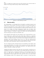
Evaluation of the work .......................................................................................... 100
9.1 Maintainability ........................................................................................... 102
9.2 Usability ..................................................................................................... 104
9.3 Testability................................................................................................... 105
10 Conclusions ........................................................................................................... 108
References ..................................................................................................................... 110
Appendix 1: Parameter group box ................................................................................ 113
Appendix 2: File builders editor ................................................................................... 114
Appendix 3: File sets editor .......................................................................................... 115
Appendix 4: Files editor ................................................................................................ 116
Appendix 5: Model parameter editor ............................................................................ 117
Appendix 6: Parameters editor ...................................................................................... 118
Appendix 7: Address spaces editor ............................................................................... 119
Appendix 8: memory maps editor ................................................................................. 120
Appendix 9: Memory map editor .................................................................................. 121
Appendix 10: Address block editor .............................................................................. 122
Appendix 11: Register editor ........................................................................................ 123
Appendix 12: Views editor ........................................................................................... 124
Appendix 13: Environment identifier editor ................................................................. 125
Appendix 14: Ports editor ............................................................................................. 126
Appendix 15: Bus interfaces editor ............................................................................... 127
Appendix 16: Channels editor....................................................................................... 128
Appendix 17: Cpus editor ............................................................................................. 129
Appendix 18: Other clock drivers editor....................................................................... 130
LIST OF SYMBOLS AND ABBREVIATIONS
FPGA
IP-block
IP-XACT
SoC
Metadata
Verilog
VHDL
VLNV
XML
Field-programmable gate array
Intellectual property block
XML based metadata-format for automated configuration and
integration of electronic systems.
System-on-Chip
A general term for descriptive data.
Hardware description language for modeling digital circuits.
Very High Speed Integrated Circuit Hardware Description
Language
Vendor, Library, Name, Version.
eXtensible Markup Language.
1
INTRODUCTION
This master’s thesis is related to FPGA-based embedded system design and presents
development work for an open source design tool called Kactus2 [1].
A typical embedded system product consists of a hardware platform and software being
executed on one or more programmable cores. Hardware platforms consist of systemon-chips (SoC), which consist of reusable intellectual property blocks (IP-blocks). An
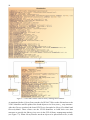
IP-block is a reusable unit of logic that is owned by one party [2]. Figure 1.1 depicts an
example case of a system hierarchy. One platform may contain several different
implementations and, on the other hand, same implementation may be ported on several
different platforms.
Figure 1.1. System hierarchy
Today digital systems are getting larger and more complicated at an increasing pace.
The integration of IP-blocks into larger systems and porting of these systems to
different platforms has become a complex task. Traditionally the solution for these
problems has been to develop IP-libraries in several different implementation languages
such as VHDL, Verilog and C-programming language. This kind of approach results in
having systems, which contain IP-blocks implemented in several different
implementation languages, radically expanding the range of possible configurations.
The used design tools also require additional information on the systems, which
increases the configuration count even further. This creates demand for tools, which
efficiently manage the different configurations and variations of products on the market.
IP-XACT metadata provides a possibility to package the IP-block’s essential
information in a tool, implementation and vendor neutral way. The purpose of this
2
Thesis is to develop a tool, which understands IP-XACT and is able to manage the IPlibrary based on IP-XACT. Kactus2 is designed to help the management and integration
of reusable intellectual property blocks.
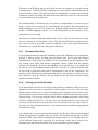
The Thesis is organized as follows. The next Chapter introduces the concepts of IPblock and System-on-Chip. It also explains the basics of IP-XACT, a metadata standard
for configuration and integration of IP-blocks. The third Chapter lists related tools on
the market. Chapter four introduces the Kactus2 tool, which is the main focus of this
Thesis. The fifth Chapter lists the use cases of library management and sixth Chapter
the different phases of IP packaging. Chapters seven and eight explain the
implementation details of library management and IP packaging module. The ninth
Chapter contains evaluation of the presented modules and finally Chapter ten contains
the conclusions of the topics discussed on this Thesis.
3
2
IP INTEGRATION
This Chapter explains the basic principles of IP-blocks and System-on-Chips (SoC),
what they are and what they can be used for. The basics about IP-XACT, a standard
used to package IP-blocks for easier reuse, are also explained. Finally the different
phases to add new IP-blocks to the library and the extensions made to the original
standard are depicted.
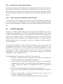
2.1
System-on-Chip
A System-on-Chip consists of several IP-blocks and contains almost all different parts
of the system on a single VLSI chip [2]. While testing and verification of a single IPblock focuses on making sure the block functions correctly, the main focus on SoCs is
checking the cooperation of IP-blocks instantiated on the chip. In case of large designs
the workload can be divided into smaller portions by dividing the system hierarchy into
smaller subsystems. This way each level has fewer components to test, therefore making
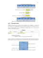
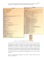
the testing and verification process simpler. Figure 2.1 shows an example of a small
SoC, where several IP-blocks are connected together via HIBI-bus [3].
Figure 2.1. A System-on-Chip containing 4 IP-blocks, a bus and 5 external interfaces.
Figure 2.1 contains a large light blue rectangle which is the HIBI-bus connecting the
other IP-blocks. On the right side, there are blocks performing different functionalities
4
such as PCI-Express adapter, memory controller and a DMA-controller. On the edges of
the Figure, the external interfaces of the chip are shown, e.g. the reset interface.
The SoCs today may be very complicated containing several different clock regions and
dozens or hundreds of IP-blocks [4]. An example of modern SoC is the Texas
Instruments OMAP platform for mobile applications [5]. The OMAP platform contains
e.g. two ARM Cortex A9 CPUs, vast scale of I/O peripherals, a DSP processor and a
graphics accelerator. This level of complexity sets great demands on testing and
verification processes. Reuse of IP-blocks can greatly ease this workload when one can
use the same blocks and subsystems that have already been tested previously.
In addition to the large number of IP-blocks, also different configurations of the same
system set challenges for the developer. For example, in the example SoC, the PCIeadapter could be replaced by an Ethernet interface while the rest of the system remains
the same. When developing a new system it is not wise to always start all over from
scratch, but making use of the old systems saves a lot of time and effort. One way to
upgrade the system can be to develop a new software implementation which runs on the
old hardware platform, until a new hardware implementation reaches the market. On the
other hand, old software may be run on a new hardware platform or both of them can be
upgraded simultaneously. In each case, it must be explicit which configurations have
been tested and verified in each product.
2.2
IP-block information contents
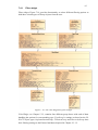
As an example, Figure 2.2 depicts the directory structure of the HIBI-bus showing the
different versions (2.0 and 3.0), the documentation files (directory doc), implementation
files (directory vhd) and the test benches (directory tb).
Figure 2.2. The directory structure and files of HIBI-bus.
5
The owner of an IP-block may use the block in one's own systems or it can be licensed
to another party. Typically IP-block implements a clearly defined functionality and can
be used in many systems. The block may also be configurable to improve its reusability
in different systems. By using the same block more than once, the cost of development
can be spread among several parties.
The configurability of IP-blocks may vary greatly. Configurability of a transistor-level
design is minor but respectively one can estimate, for example, the performance and
timing limitations very well. In contrast an IP-block which consists of source codes
written in VHDL-language may be very well configurable but the estimates for its
performance are very rough.
One IP-block contains much more than just the source codes, the file count may easily
increase to dozens or even hundreds of files. The better the IP-block is documented, the
easier it is to reuse it in another system. In addition to the source and documentation
files the IP may contain files for testing and verification.
2.2.1
Documentation files
A user manual is the most important subsidiary deliverable. Without the user manual the
IP-block is almost useless for third party developers who do not know the detailed
implementation of the block. In addition to the user manual, the documentation files
may include class, block and sequence diagrams, which explain how the IP-block
functions. For hardware IP-blocks, the datasheets must explain how to configure and
boot the IP. The documentation material should reveal how to connect the block with
the rest of the system and what kind of requirements it sets for the connections. The
interfaces of the IP-block must be documented clearly. For example in software IPs, the
class interfaces must be defined, and for hardware IPs the ports and their timing
diagrams must be included.
2.2.2
Testing and verification files
A test plan should reveal how the testing of the IP-block is planned: what test cases are
planned and how the block is expected to behave in those test cases. The test report
should explain what tests were executed and how the IP actually behaved in those tests.
Especially all deviations between the expected behavior and the actual behavior must be
reported clearly. Test coverage analysis can be used to estimate the quality of the testing
and how reliable the IP-block is. Test log can be used by third parties to repeat the tests
and verify the block behavior with the given test cases themselves. The types of the test
logs may vary from simulation log files to screenshot videos recorded during graphical
user interface testing.
A test bench can be used to automate the testing of the IP-block. The test bench should
include the automatic checking of the test results. For hardware blocks the test bench
may be a VHDL entity which instantiates the design under test. For software there are
several software frameworks, especially for unit testing, which can be used to write
automated tests that check the results of the tests against the expected outputs.
6
2.2.3
Source files of the implementation
The most essential part of the IP-block is the implementation files. If there are other IPblocks that are needed for the main block to function, then also the source codes of
those blocks must be included. An example of this could be a third party library used by
the IP. For hardware IP-blocks there may also exist some software components, such as
drivers.
2.2.4
Files to help the initialization of the IP-block
The initialization of the IP-block is much easier if the block includes an example use
case where the block is instantiated and used. A makefile will help compiling the IP and
lists its internal dependencies. Synthesis scripts are similar auxiliary files for hardware
IPs.
2.3
IP-XACT-standard
IP-XACT is an XML format standard developed originally by SPIRIT Consortium for
configuration and integration of electronic components and designs [6]. The current
version 1.5, that Kactus2 supports, is also approved as IEEE 1685-2009 standard. The
purpose of the standard is to provide tool, implementation and vendor neutral format to
describe the essential information of an IP-block. Metadata is a general term for
descriptive data. In this case its purpose is to list, for example, the interfaces and file
sets of an IP-block.
The reusability of the block can be increased by making it easier to port it from one
development environment to another. Therefore a tool-neutral approach is very
beneficial. The implementation-neutral approach means that the metadata does not limit
the language the block is implemented in. This way there will be no unnecessary
dependencies in the IP library between implementation languages and different
configurations can be managed easily [7].
The standard defines 7 different types of IP-XACT documents [6]:
1. Component describes a single component in the library. For example the
interfaces and files for the component are listed here.
2. Design contains a hierarchical design which consists of the components
instantiated in this design. It is a kind of textual block diagram of the system.
3. Design configuration defines the configurations used in a hierarchical
design.
4. Bus definition contains the general information of a hardware bus.
5. Abstraction definition defines the logical signals and attributes of a hardware
bus.
6. Generator chain defines a group of scripts that can be used e.g. for
automatic configuration of a component.
7. Abstractor is used to combine designs from different abstraction levels.
7
Each document creates a single object in the library. The different objects can be
uniquely identified by a VLNV-identifier. The identifier consists of tuple {vendor,
library, name, and version}. All references between the documents are made using the
VLNV-identifier.
The library can be better managed when the dependencies between IP-blocks are
documented and in a format that can be read by computers. This way it is possible to
clearly display to users the dependencies between the components and how a single
component consists of sub-components. This also facilitates the management of thirdparty libraries because the developers are not needed to explain to integrators, what
components depend on each other and what kind of requirements they set for their
interfaces. By agreeing on the naming policies of the VLNV-identifiers, it is also
possible to manage the dependencies across library bounds because the dependencies
are seen in references from one object to another [8].
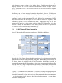
2.3.1
IP-XACT based IP-block integration
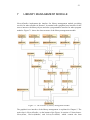
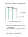
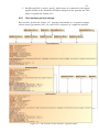
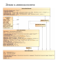
Figure 2.3 depicts the different phases to add a new IP-block to the library.
Figure 2.3. Adding a new IP-block to the library and composing of new blocks [9].
The left side of the Figure displays the different phases of the design process and the
right side the documents being handled in each phase. When adding a new IP-block to
the library, it must be packaged with IP-XACT metadata. This makes it possible to
automatically manage the IP library when the data is in computer readable format. The
user can search for a single component from the hundreds or thousands of components
in the library by defining search criteria and filters to display only the desired types of
components.
In phase 2 a new hierarchical component is created by creating a design description,
which lists the components instantiated with their mutual connections. The created
hierarchical component is also displayed in the library among the other components and
it can be instantiated itself in some other hierarchical component to create deeper
hierarchies of sub-systems.
8
To create a final product, phases 3 and 4 are used. Phase 3 sets the used configurations
and settings for each component instance. Phase 4 generates the needed files, for
example the structural-level VHDL code for the top-level component. Finally the source
codes can be e.g. synthesized using the tools provided by an FPGA-vendor.
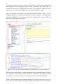
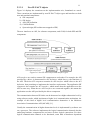
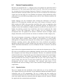
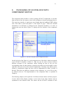
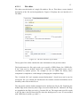
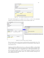
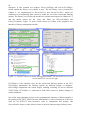
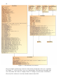
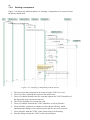
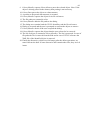
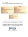
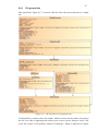
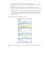
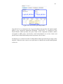
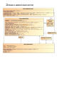
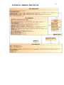
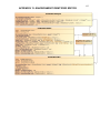
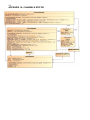
Figure 2.4 displays a screenshot of the component editor in Kactus2, used to create a
metadata package for a component. The bottom of the figure displays a part of the saved
metadata for HIBI-bus. The metadata displays the information of a single VHDL file
and what compile options are set for it.
Figure 2.4. The component editor and the saved XML data for a single VHDL file.
The part marked with number 1 contains information for the path and options of a single
file. The path is a relative path from the XML file to the source file. The part marked
with number 2 contains the compile commands and options for different file types.
The more detailed and strict the metadata package of an IP-block, the more precise are
the search results and statistics of the library. When the packaged data is correct and up-
9
to-date, it is possible to perform different types of data mining operations on the library.
For example, one could generate a weekly report of the library reporting, not only the
number of IP-blocks, but also their maturity levels, complexity and dependencies.
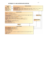
2.3.2
Elements of a component
Each IP-block will add at least one component-document to the library. Components
can be used to describe processors, peripherals such as DMA controllers, and buses like
the HIBI-bus. Component contains several elements used to describe different types of
information. Not all elements are required for a single component and different types of
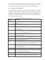
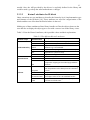
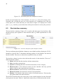
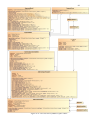
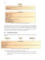
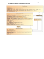
components will use different elements. Table 2.1 describes some of the elements of a
component supported by Kactus2 [6].
IP-XACT
element
VLNV
Table 2.1. Different elements of a component.
Description
An unambiguous identifier used to identify the component in the
library.
Bus interfaces
Describes all external interfaces of a component. Bus interface
groups ports together to form a bus.
Channels
Describes interconnections between interfaces inside of the
component. This element can be used to describe a bus connecting
interfaces together.
Address spaces Describes the addressable space seen from bus interfaces with
interface mode of master. This can be used to describe the address
space seen by a CPU through bus interface.
Memory maps
Describes the addressable area seen through bus interfaces with
interface mode of slave.
Ports
Describes a list of ports for the component. These are used to
describe the external connections of the component.
Model
Describes the parameters needed to configure the model
parameters
implementation specified in a view.
Views
Describes the different views of a component. Component may have
different views. For example one view for the RTL implementation
and one for the written documentation of the component.
File sets
Describes groups of files that can be e.g. grouped by their function.
One file set may contain the source files and other the documentation
files of the component.
Cpus
Describes the programmable processors of the component.
Other
clock Describes clock signals within a component that are not directly
drivers
associated with an external port of the component. For example
generated clock signals can be listed here.
Parameters
Describes parameters that can be used to configure the component.
Description
Contains the textual description of the component. This can be used
to document a human readable description of the component.
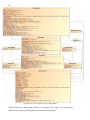
10
The components in the library can be divided into two categories by their internal
structure:
Non-hierarchical components do not contain any kind of metadata
documentation of their internal subcomponents. They are not dependent of other
components through VLNV-references and contain all source codes and
documentation they need in their own metadata package. The metadata package
of these components refers directly to the files in its file sets. The only VLNVreferences are bus and abstraction definitions, if any.
Hierarchical components consist of other IP-XACT sub-components. These
sub-components can be non-hierarchical or hierarchical to form deeper
hierarchies of system design. A Hierarchical component contains VLNVreference to design, which instantiates the sub-components. It does not contain
the files of the sub-components because they are contained in the subcomponent descriptions. The hierarchical component may contain structural
level source codes. The structural level code can also be generated automatically
when the component instances and their connections have been defined, like in
the example SoC on page 3.
2.3.3
Extensions to the standard
Kactus2 uses some extensions to the original IP-XACT standard. These extensions are
designed to improve the usability and efficiency of the tool. The largest extensions are
related to the software design process, which is itself out of the scope of this work.
Figure 2.5 depicts the used extensions and their relation to the original IP-XACT
standard.
Figure 2.5. The extensions to the scope of IP-XACT standard [10].
11
2.3.3.1
New IP-XACT objects
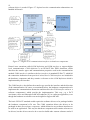
Figure 2.6 displays the extensions on the implementation axis, formulated as a stack.
These extensions are implemented by new IP-XACT object types and interfaces to both
new and standard components:
a) SW component
b) SW design
c) API (SW) definition
d) COM definition
e) System design (SW architecture mapped to HW)
The new interfaces are API, for software components, and COM, for both HW and SW
components.
Figure 2.6. New IP-XACT object and interface types.
API interfaces are used to connect SW components to each other. For example, the API
provided by a driver is documented in API definition, which lists e.g. the functions of
the API. The driver SW component contains an API interface which refers to the API
definition, thus promising to implement the interface requirements. The application SW
component also contains an API interface, which means that the application uses the
API in some way. When the two API interfaces are connected together, this means the
application uses the API provided by the driver component.
The communication between IP-blocks can be abstracted to a higher abstraction level by
using software stacks, which implement a higher level communication mechanism. An
example of this kind of higher level communication abstraction is the Multicore
Association Communications API (MCAPI) [11].
Usually the communication in higher abstraction levels is implemented by software run
on a processor. The software implements the logical communication channels but the
underlying hardware components do not know of these logical connections. For these
logical communication channels to be functional, some kind of hardware dependent
12
software driver is needed. Figure 2.7 depicts how the communication abstractions are
handled in Kactus2.
Figure 2.7. Higher level communication interfaces in hardware components.
Kactus2 uses extensions called COM definition and COM interface to support higher
level communication. COM definition is an IP-XACT-like XML document, which
describes the transfer types and communication properties used in the communication
method. COM interface is similar to the bus interfaces in standard IP-XACT, which lift
the connection abstraction from port-level to bus-level. COM interfaces are included in
the hardware component and they contain a reference to the COM definition which is
implemented by the interface.
The COM Interface also defines the transfer type used in the interface and the direction
of the communication. Of course, as mentioned before, the hardware component doesn’t
implement the communication abstraction and therefore the COM interface refers to a
software component(s) which provide the implementation. This way, e.g. a DCT
accelerator can be used through an MCAPI endpoint [11] in a software application, even
though the hardware accelerator was not designed to support MCAPI.
The basic IP-XACT standard would require the software drivers to be packaged within
the hardware component’s file sets. The COM extension allows the drivers to be
packaged in their own software component, which defines its own software interfaces to
be used in an application. This way the hardware component still contains reference to
its drivers, but the drivers can also be re-used to build other custom software stacks if
13
needed. Also, the API provided by the drivers is explicitly defined in the library and
could be used e.g. to help the software/hardware co-design.
2.3.3.2
Kactus2 attributes for IP-block
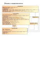
Other extensions are new attributes to describe the hierarchy level, implementation type
and firmness of the IP-block [10]. These attributes are used for categorization of the
blocks and have no effect how the blocks behave in the tool.
Making use of these attributes allows library handler to filter the objects shown to the
user and also to display the object type to user with a correct icon in the library views.
Table 2.2 lists the Kactus2 attributes, their possible values and their explanations.
Table 2.2. The different Kactus2 attributes.
Attribute scope
Product Hierarchy
Implementation
Attribute value
Global
Product
Board
Chip
SoC
IP
HW
SW
SYS
Firmness
Template
Mutable
Parameterizable
Fixed
Description
Does not fit into any other category.
Represents a final product.
Represents development- or final hardware
platform e.g. a circuit board.
Represents a chip e.g. some specific FPGA-chip.
Represents a system-on-chip.
Represents a single IP-block.
Hardware implementation.
Software implementation.
Contains information about the software
component mapping to the underlying hardware
platform.
A model that can be used as a base when creating
new components to the library but can’t be used
as such.
Component is fully modifiable.
Component contains parameters that can be used
to configure it but it can't be modified further.
Component can’t be configured in any way and it
is frozen to its final state.
14
3
RELATED TOOLS
The system design tools on the market can be divided into two different categories.
There are tools used to compose systems from higher abstraction level models e.g. by
generating executable program code from UML-models. On the other group are the
tools that manage completed IP-blocks and integrate them into larger entities. The
Kactus2 software, described in this Thesis, belongs to the second group. Typically the
tools in the second group require that the blocks contain some kind of metadata to ease
the integration and configuration of the sub-blocks.
Mentor Graphics provides a tool called HDL Designer, which contains a graphical user
interface to instantiate and connect sub-blocks by drawing lines between the ports of the
blocks. HDL Designer supports IP-XACT standard but also enables functional
descriptions such as state machines [12].
Altera provides a tool called SOPC Builder as a part of their Quartus II development
software [13]. In this tool, the IP-blocks are packaged as library components and are
connected to each other by using a graphical tool. When the connections are made,
SOPC Builder generates the needed connection logic automatically between the blocks.
The metadata format used by the tool is not standardized and it is completely tool
specific and the connection network is always Avalon bus developed by Altera. Altera
also provides a tool called QSys which is the newer version of SOPC but the basic
principle of the tool is similar [14].
ARM has developed a tool called CoreLink AMBA Designer [15]. The tool supports IPXACT versions 1.2 and 1.4 which are older than the current IEEE standard 1685-2009
which Kactus2 uses. Version 1.4 is quite similar to the latest version but contains
differences e.g. in the register elements. The AMBA Designer uses the ARM Fabric IPs
and allows the integration and configuration of those IP-blocks into larger systems. The
tool outputs a top-level Verilog file which connects the different IPs together and also
the top level IP-XACT description which can be used in the next level of integration.
Synopsys has a CoreBuilder tool which can be used to create IP-XACT metadata
packages for a component [16]. The tool is similar to the component editor module
presented in this thesis. CoreBuilder supports both the Synopsys’ coreKits and also IPXACT components. It asks the user to input the details of the IP block and then creates
the desired package to be used in an integration phase. CoreAssembler is the integration
tool for assembly and configuration of an IP-based subsystem [17].
Duolog provides an integration tool called Socrates Weaver [18]. It supports importing
and exporting of IP-XACT to integrate IP-blocks into larger systems and then creating
the metadata package for the entire system.
15
Magillem has IP packaging tool called Magillem IP-XACT Packager [19]. It enables
user to import existing source files such as VHDL to create an IP-XACT description,
which can be used to build the IP library. Magillem Platform Assembly is the design and
integration tool, which uses the IP-blocks created with the packager to create larger
systems [20].
OpenTLM environment provides tools for the development and verification of
SystemC/TLM IP models. The OpenTLM IDE integrates an IP-XACT editor which can
be used to create/edit IP-XACT metadata packages [21]. The tool is open source and
can be downloaded in the project’s SourceForge page.
There are not many tools for packaging software blocks. Of course the different project
files of development platforms, which contain the files needed by the project, their
dependencies and compilation options, could be considered as metadata. This kind of
metadata is not standardized and the project files are not interoperable between different
tools and sometimes not even with different versions of the same tool. The closest tool
neutral standard for software packaging might be the Linux packet management system
[22] but it is meant for higher level packets used to ease the installation of software for
personal computers.
16
4
OVERVIEW OF KACTUS2
Kactus2 is a metadata based design tool for embedded products. It aims to ease the
reuse of IP-blocks with the help of a graphical user interface. The goal is to provide a
tool, implementation, and vendor independent method for IP-integration using IPXACT-metadata. The presented Kactus2 version is 2.0. Kactus2 can be used for the
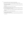
following tasks.
a) Package existing IPs to create “electronic datasheets”.
b) Manage IP-XACT library by importing libraries from other vendors, checking
library integrity and exporting IP library.
c) Create quick draft blueprints for IP, System-on-Chip, printed circuit board
(PCB) and product, all stored in IP-XACT format.
d) Create system designs, used to map SW to HW.
e) Create SW architecture using higher level communication abstractions.
f) Configure designs to increase reusability of IPs.
g) Generate structural top-level VHDL code for HW designs.
h) Generate code templates, including VHDL entities, ports and C headers, for new
IPs based on their IP-XACT descriptions.
i) Generate synthesis and simulation scripts for designs.
j) Generate combined documentation for whole systems through all hierarchy
levels of a product.
Figure 4.1 displays a screenshot of Kactus2 user interface with the IP-packaging module
open.
17
Figure 4.1. Screenshot of Kactus2 with component editor.
On the left side of the screenshot is the library management module, which is presented
in Chapter 5. The item in the middle is the component editor which is the module used
to create the IP-XACT packages for components, explained in Chapter 6. These two
modules are presented in this Thesis in detail but the other parts of the software are
introduced only briefly.
The component preview is used to display a preview what the currently selected
component looks like in the integration phase. This helps user to find the correct
component in the library, because it shows the interfaces of the component visually. The
message console is used to print notifications and possible errors to user. The help on
the right is context sensitive and changes when user selects different elements on the
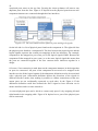
component editor. Figure 4.2 shows another screenshot of Kactus2 with the design
editor.
18
Figure 4.2. Screenshot of Kactus2 with HW design editor.
Figure 4.2 displays a design editor in the middle containing three components
instantiated. The design editor is used in the integration phase of the development to
instantiate components created with the component editor. The left side of the Figure
displays a new object dialog where the user can select the type of object to create. On
the right there are several different context specific editors which are used e.g. to edit
the details of the component instances. Whenever user selects an item in the design
editor, an editor for the item is presented. For example, the user has selected a bus
interface and the details of the interface are shown on the right.
Kactus2 uses different icons to display the object type to the user in the library views, as
depicted in Figure 4.3. The VLNV identifying the object is seen on the right side of the
icon.
Figure 4.3. The icons for different object types.
19
4.1
Kactus2 implementation
Kactus2 was implemented in C++-language using cross-platform Qt application and UI
framework [23]. The version used in this work is Qt 4.8.3. There were several reasons
for selecting Qt as the development framework. Kactus2 is an open source project so a
framework which is released with an open source license was desired. One of the major
reasons was also the ability for cross-platform development, which enabled the release
of Kactus2 for several different operating systems such as Linux, Windows and Mac OS
X in the future.
Python language was also considered when selecting the framework. It has large
number of GUI frameworks available and some of the features of Kactus2, such as
XML parsing and VHDL code generation would have been easier to implement using
Python. However, this would have made the installation package for Kactus2 more
complex because also installation of Python interpreter would have been needed. Use of
Python was therefore rejected. Java would have also been an option but the visual
outlook of Java GUI frameworks, such as Swing, was not satisfactory to the
development team. The graphical user interface of Kactus2 consists of widgets, which
display information, interact with the user and act as containers for other widgets [24].
The used development environment is Microsoft Visual Studio 2008 [25] with Qt’s
Visual Studio add-in installed, which enables Qt development on Visual Studio.
Although the development and testing has been mostly done on computers running on
Windows operating systems, other platforms have been considered and platformdependent code has been avoided. Kactus2 has been tested to run on at least Linux’s
Ubuntu and Debian distributions as well as Windows XP and 7 in both 32 and 64 bit
versions.
Agile software development methods have been used in the development process. There
have been several different parties submitting demands for the tools and the demands
have changed several times during the development. Therefore, the traditional waterfall
method wouldn’t have suited for this type of development because of the rapid changes
in system requirements. The Kactus2 development team contained two key coders,
which performed the unit testing of modules and also part of the system testing. For
system testing, there has been several parties which have used the tool in both the
development and the release environment. The extremely agile nature of the
development has forced re-writing of some of the codes due to major changes in system
requirements.
4.1.1
Signals & slots
The use of signals and slots mechanism of Qt enables the use of very modular code
[26]. Signals and slots are an alternative for the traditional callback mechanism which is
commonly used in GUI programming. The use of signals and slots enables the
communication between two classes which do not know of each other. It is enough that
some code module makes the connection from the signal to the slot. Figure 4.4 depicts
the signals and slots communication mechanism.
20
Figure 4.4. The signals and slots communication mechanism.
The implemented modules and the whole Kactus2, use signals and slots to improve the
modularity of the software. For example, the message console has two slots: one for
error messages and one for notifications. None of the other modules are aware of the
message console but when they emit a notification signal, it is forwarded to the message
console, which then prints the message for user to see. The message console prints
notification and error signals with different outlook to provide a clear distinction
between the message types.
21
5
MANAGEMENT OF THE LIBRARY
The library management module allows user to navigate through the object hierarchy
and view dependencies between components. The user can search for objects by their
VLNV identifiers or object attributes, which makes finding the correct object easier.
The module also checks the validity of the objects and reports if there are objects with
invalid or missing data.
LibraryHandler is the class which implements the interface for library management
module of Kactus2 software. It does not only manage the components and their designs
but also the interface definitions of hardware buses and software objects. Chapter 7
depicts the implementation of the library management module. The different objects are
identified by using the previously mentioned VLNV-identifier. By creating naming
policies for VLNV-fields, it is possible to unify and clarify the library structure, thus
keeping the IP-blocks easier to manage [8]. Moreover, our extensions (of Chapter 2.3.3)
also aid in management.
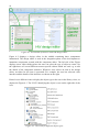
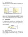
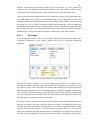
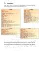
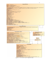
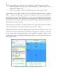
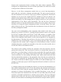
Figure 5.1 shows a screen shot of the two library views of library management module.
22
Figure 5.1. The hierarchical view and the VLNV-tree view.
The hierarchical tree view on the left displays the dependencies between different
objects. Each component on the tree contains the designs it refers to and the designs
contain the components instantiated in them. The non-hierarchical flat components,
such as SRAM_512KB, obviously do not contain any children because they lack the
design reference. On the view user can see the entire structure of an example product
samos_2012 which is the topmost object on the tree. The product contains a board level
component which contains a chip and so on, until the hierarchy reaches the IP-blocks
written in VHDL-language on the bottom of the hierarchy.
The VLNV tree on the right side is constructed from the VLNVs of the objects. The
appearance of this view can be greatly influenced by naming policies. The tree is
constructed by taking one of the VLNV-fields on each level to create a four-level deep
tree structure. For example the full VLNV of the object on the top of the view is
TUT:board:altera_de2_board:1.0.
23
Component de2_samos_soc is marked with red on both views. This means that the
component is not in valid state and contains some errors. The error could be a missing
file or invalid reference to an object that does not exist in the library. User can explicitly
ask the library handler to do error checking on the objects of the library and view the
error reports to fix the objects into valid state. The error reporting is explained in more
detail on Chapter 5.1.2.
Kactus2 attributes extend the scope of IP-XACT, as depicted in Chapter 2.3.3.2,
allowing users to document e.g. the structure of the development board to the IP-XACT
metadata. This way it is possible to control the documentation, source codes and
configurations of an entire product and get the product data management in a machine
readable format. When the library contains information on what configurations and
platforms a product uses, it could be possible for example to build a matching test
environment automatically [27].
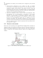
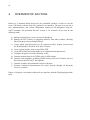
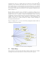
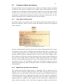
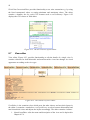
Figure 5.2 displays the 11 use cases of the library management module which are
explained in the following Chapters.
Figure 5.2. Use cases of library management.
5.1
Entire library
Some operations are directed to the entire library instead of single items. For example,
searching for new items on the hard drive will cause all items to be re-parsed.
24
5.1.1
Search for new items on the disk
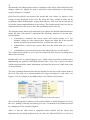
The "Library" section in the ribbon menu on top of Kactus2 contains icon to set the
directory paths for the libraries. Figure 5.3 shows the icon in the user interface of
Kactus2.
Figure 5.3. Set library paths for Kactus2.
The user can define library paths that are used as base when starting to search for new
library items. When Kactus2 is started it takes these paths and starts to search for IPXACT objects in those directories and their subdirectories. The found objects are
displayed to the user in library views described earlier. IP-XACT objects are searched
by seeking for IP-XACT-related tags in all files with XML suffix. User may start the
library search at any time when Kactus2 is running. Together with the search, an
integrity check is done to the library objects to find possible errors in the library.
Integrity check is explained in more detail in Chapter 5.1.2. The different phases when
searching for objects on the disk are explained in Chapter 7.5.2.
5.1.2
Checking library integrity
Most of the library objects contain references to other objects via VLNV-identifiers. All
hierarchical components require these references to design and configuration files but
also non-hierarchical components may contain bus interfaces that refer to a bus
definition. Components also contain references to files saved on the disk in form of
relative file paths. Third category is references within a document. For example, bus
interface groups ports together to form a bus by listing port names that belong to the
interface.
If any of these refers to an item that does not exist, the object is no longer in valid state
and it might not work correctly. A source file may be missing or renamed, thus breaking
the IP-block. On the other hand, a bus interface may refer to a port that does not exist,
which causes a conflict between metadata and the actual source implementation and will
result in problems during the integration phase.
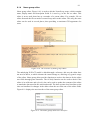
Figure 5.1 displays the library views where one object is displayed in red meaning that
the object is not valid. The objects can be opened to an editor for closer inspection and
errors can be corrected. During the integrity check the library handler also provides an
error report, which is printed to the message console in Kactus2 user interface,
displayed in Figure 4.1. Each erroneous object is listed and beneath it, the errors it
contains. Finally, a summary of different error types found in the library is printed.
Figure 5.4 displays an example of an error report and the summary of integrity check.
25
Figure 5.4. The summary of integrity check and an example of an error.
5.1.3
Parsing item dependencies
The hierarchical view visualizes both the direct and indirect dependencies of the
components. The library handler also provides interface for other modules to get a list
of dependencies of the library object. The handler can tell which other objects a
component needs, but also which components need the specified object. This way it is
possible to check the dependencies in both directions of the hierarchy.
This functionality can be used e.g. when opening a component in the component editor.
If the component is instantiated in one or more designs, the user is informed which
components are affected. Figure 5.5 shows a dialog where the user is asked if he is sure
he wants to edit the component, which is a sub-component in a hierarchical component
named de2_sdram_example.
Figure 5.5. A warning informing about the implications of editing the component.
5.2
Item management
The following use cases are directed specifically to the selected item. These use cases
are available through the context menu in the library views.
5.2.1
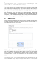
Create new item
Library handler allows a user to create new items to the library through the context
menus in library views. See Figure 5.6 for an example.
26
Figure 5.6. Adding a new item to the library.
The context menu allows the user to select what type of object is to be created. After
selecting the correct action, a dialog is opened where the user can input the VLNV for
the new object. The VLNV of the selected object is automatically set to the dialog as
default for usability reasons.
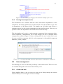
5.2.2
Open item for viewing or editing
Library handler displays the objects in the library in two different views as explained
earlier. Both views enable the user to open the object in an editor for more detailed
viewing. Figure 5.7 displays the context menu used to open the editor.
Figure 5.7. Open object for editing.
Different object types have their own editors on Kactus2. Components are edited by the
component editor, which is explained in this thesis. Other editors are not addressed on
the thesis but the library handler selects the correct editor automatically based on the
object type. When opening an object, the library handler reads the XML formatted IPXACT file saved on the disk and parses its contents into a data structure. After this, the
library handler selects the correct editor for the object type and forwards the data
structure to it.
Figure 5.7 displays two options to open a hierarchical component. The selected option
on top "Open HW Design" opens the hierarchical view of the component, which
displays the contents of the design and the components instantiated in the design. The
operations of opening a hierarchical design are explained in Chapter 7.5.1. The lower
"Open Component" opens the component editor, which is explained in detail in Chapter
6.
27
5.2.3
Open the metadata to XML editor
Sometimes the user may need to open the selected document in an XML editor instead
of the IP-XACT editors in Kactus2, see Figure 5.8 for example. This option opens the
file in operating system’s default XML editor. However, usage of Kactus2 editors is
recommended because they provide support for error checking and help the user when
creating references between objects.
Figure 5.8. Open document in XML editor.
5.2.4
Save item
As mentioned before, each object type has its own editor that handles the modification
of the data structures. However, the library handler takes care of the saving process
itself. When the user wants to save the modified object, the library handler takes the
modified data structure and writes it to the disk. If the object is new and is not yet in the
library, the user is asked to select a path to which the XML file is written into. If the
object was already in the library, the handler knows the location and overwrites the
previous file. Because the files are overwritten, it is recommended to use some version
control system, such as SVN or Git, to help restore previous versions of the objects.
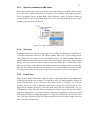
5.2.5
Export item
The user may wish to hand over a single IP-block, or part of the library, for a third party
without disclosing the whole library. To make this easier, the library handler contains an
export function that can be selected in the context menu, as in Figure 5.9. Kactus2
prompts the user to select a destination directory to export the selected object to. The
target may be another directory on the same disk, a directory on network disk, or e.g. a
USB-memory. After this, the library management module copies the selected object,
and all its dependencies, to the new location. Both direct dependencies of the object and
indirect dependencies through other objects are copied to maintain the objects in a valid
state. This way, all needed IP-XACT objects and files are copied with a single click and
files are not lost accidentally.
28
Figure 5.9. Export item.
The exporting of files to a new location is only possible when the file references within
components are made with relative file paths. This is why component editor always
selects relative paths when adding files to the component metadata.
5.2.6
Remove item
The VLNV-tree view allows the user to remove objects from the library. When the
object is selected to be removed, the handler checks the library if there are other objects
in the library that are tightly associated with it and should also be removed. This check
is done to keep the library as clean as possible and to avoid accidentally leaving
unnecessary objects to the library. Also, when removing a component, its files might
need to be removed from the disk.
Tightly associated objects are:
In case of hardware buses, bus definition and abstraction definition. If the other
is removed, it is often unnecessary to preserve the other. This is why the tool
suggests removing both objects.
Hierarchical components contain a design configuration and a design. A
hierarchical component may contain several different configurations and designs
and when removed also all of these are suggested to be removed.
Before anything is removed, the user is presented a dialog to select which library
objects and files to remove. After clicking "Ok" these items are removed from the
library and disk. If the user wants to save some of the items, they can be unchecked in
the dialog and they will not be removed. Figure 5.10 displays the dialog asking if the
user is sure he wants to remove a hierarchical component altera_de_II_demo and its
configuration and design. Also the files contained in the component are listed.
29
Figure 5.10. The confirmation dialog for the user to select, which items to remove.
5.3
Viewing
The following use cases affect how the library looks like. They do not change the
library structure but only the visual outlook of the library views.
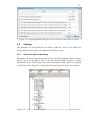
5.3.1
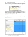
Search for item in the library
The number of objects in the library may become very large, making it hard to locate a
specific object in the library. This is why the library handler provides a searchfunctionality in the VLNV-fields. Only objects that match search criteria are displayed
in the library views. Figure 5.11 shows how the search looks like in the user interface.
Figure 5.11. Only items that match the search criteria are shown in the search results.
30
Only objects that's VLNV-identifiers contain the given keywords are shown. The search
results contain all object types such as hibi_segment component and hibi_clocks bus
definition. The user may also use wildcards (?) and (*) to replace characters in search
terms.
5.3.2
Filter item types
In addition to the search functionality, the library handler provides option to filter
objects based on the object types. This can be used together with the search terms e.g. in
order to search for “mutable” hardware components containing name "hibi". Filtering
uses the Kactus2 attributes (Chapter 2.3.3.2) and allows the user to select which
attribute options are to be shown in the library views. Figure 5.12 displays the menu for
selecting the filtering conditions.
Figure 5.12. Selecting the filtering conditions.
31
6
PACKAGING OF AN IP-BLOCK WITH
COMPONENT EDITOR
The component editor module is used to package IP-XACT components. It provides
help and advice but also reports errors in the metadata to help the packaging process.
The visual user interface is much more user friendly than the traditional XML editing
tools. This editor is used in the phase 1 of the Figure on page 7. When the essential
information of an IP-block is packaged in the component metadata, it is easier to
manage and reuse the block. Figure 6.1 displays the user interface of the component
editor.
Figure 6.1. The user interface of the component editor.
On the left side of the Figure 6.1 is the navigation tree of the editor, which corresponds
to the IP-XACT elements in Table 2.1. This tree can be used to browse between
different elements of the component. When clicking an item in the tree the
corresponding editor for that element is opened to the editor area in the middle. On the
right side is the area reserved for element visualizations. Currently, only address spaces
contain a visualization widget but more will be implemented in future versions of
Kactus2. When the user adds new elements to the component, e.g. a new file set, they
are added to the tree. The implementation of the component editor is explained in
Chapter 8.
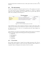
The following Chapters will explain the 23 different element-editors and their purposes
in more detail. Each Chapter contains a screen shot of the editor interface and an
explanation of the different fields. The editors edit the IP-XACT metadata of their
32
corresponding elements within a component and more detailed description of the
different fields can be found in the IP-XACT standard [6].
There are two types of editors. Summaries contain a table displaying the settings of the
items. Some elements, such as parameters, only contain a summary editor because all
element fields can be accessed in the table. Some more complicated elements, such as
files, require several editors to handle different levels of detail. All elements contain a
name field, used to identify the element, and a textual description explaining the
purpose of the element in question. The mandatory fields of each editor are marked with
yellow color. If some information is invalid, such as reference to a missing element, or
mandatory fields are empty, the element is displayed in red color.
6.1
General Editor
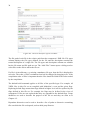
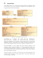
General Editor is the first editor shown to the user when he opens the component editor.
It contains the general information of a component, such as description. Figure 6.2
shows the user interface of the general editor.
Figure 6.2. The user interface of general editor.
VLNV-identifier and the path to the XML file are shown on the top of the editor. These
fields can’t be modified and if the user wants to change the VLNV then the component
must be saved as a new component. Kactus2 attributes contain the hierarchy, firmness
and implementation, of which the implementation can’t be modified (see Chapter
2.3.3.2).
The component preview box on the bottom displays how the component will look like
when instantiated in a design. The preview displays the bus interfaces of the component
33
and also the ports that are marked to be seen as ad hoc ports. In this case, there are 5 bus
interfaces.
6.2
File set summary
The files of a component are grouped together by file sets. The grouping can be based
on e.g. the file types (sources, documentation, simulation, etc.). There are 3 different
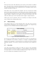
editors for the file packaging: the file set summary, file set specific editor and file
editor. File set summary is seen in Figure 6.3.
Figure 6.3. The user interface of file sets editor.
Group identifiers can be used to describe the function or purpose of the file set with a
single word. All columns can be modified in the editor to set the general information of
the different file sets. If a file set is in invalid state then the editor displays the
associated row in red.
Group identifiers can contain several identifiers and the possible options are not limited.
However, the editor suggests the following options for the group identifiers:
a) Diagnostics
b) Documentation
c) ProjectFiles
d) Simulation
e) SourceFiles
6.2.1
File set editor
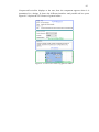
File set editor sets the details of a single file set and adds and removes files. File sets
basically group files together so they can be easily referenced by other sections of a
component. Figure 6.4 displays the user interface of the file set editor.
34
Figure 6.4. The user interface of file set editor.
The file path of each file is the relative path from the component’s XML file. File types
column displays the file types defined for the file and the description contains the
textual description of a single file. The file types and description columns are editable
but the file name and file path are not. The “Add Files” button opens a dialog used to
select files on the disk to add to the file set.
If a file is in invalid state, e.g. missing a mandatory file type, then the file is displayed in
red color. The order of files is maintained and can be changed by dragging rows. If the
compilation order of files is important then the files should be listed in the order needed
by the compilation.
The default build command applies to all files of the specified type. For example, all
VHDL files in this file set are compiled with Modelsim’s vcom and the given flags.
Replacing default flags means that flags defined in higher level will be replaced by the
flags defined in this file set. For example, the flags may be defined in the views of
component. If files are not replaced then they are appended to the default flags. Group
identifiers are used to describe the purpose of the file set and they are same as in
Chapter 6.2.
Dependent directories can be used to describe a list of paths to directories containing
files on which the file set depends, such as third party libraries.
35
6.2.1.1
File editor
File editor sets the details of a single file within a file set. This allows a more detailed
description of the file and its dependencies. Figure 6.5 displays the user interface of a
file editor.
Figure 6.5. The user interface of file editor.
The top part of the editor contains the same information as the previous editor.
The logical name of a file can be used e.g. to specify a VHDL library for a VHDL-file.
If the “only used as default”-check box is checked then the logical name can be
overridden by another process. For example in case of VHDL, the library where
component is compiled to, could change by changing the compilation flags.
The “is include file” and “contains external declarations” -check boxes can be used to
specify the file is an include file and that the file contains external declarations and is
needed by other files in this file set.
The description and the build command can be defined also file-by-file. Replacing the
default flags means that only these flags are used to build the file. Otherwise the flags
are appended to the flags received e.g. from the file set. The target name specifies a path
to the file that is derived from this file when the build process is run. It is not needed
with VHDL but is useful e.g. with C++.
36
6.3
Model parameters editor
Model parameters editor is used to add, remove and modify the model parameters of a
component. Model parameters are often used in HDL languages to pass information to
the model to configure it, e.g. generics in VHDL. Figure 6.6 displays the user interface
of a model parameters editor.
Figure 6.6. The user interface of model parameters editor.
Each model parameter has a name and a type, which is language specific. The usage
type can be either typed or nontyped. Typed parameters appear in object-oriented
languages, e.g. in C++. Non-typed parameters are found in all languages, e.g. in VHDL
all types are non-typed. Value contains the default value of the model parameter if it
isn’t assigned in the design upon instantiation.
6.4
Parameters editor
Parameters editor is used to add, remove and modify parameters of a component. Figure
6.7 shows the user interface of the parameters editor. Some sub-elements within the
component also contain parameters but the scope of parameters is always restricted to
the containing element, e.g. parameters of a view can only be used within that view.
Component’s parameters have the scope of the entire component. Value contains the
default value of the parameter.
Figure 6.7. The user interface of parameters editor.
6.5
Memory map summary
Memory map summary is used to add and remove memory maps. Memory map
specifies the addressable area seen through a slave bus interface, e.g. the registers that
other components can access (status, control). Figure 6.8 displays the user interface of
the memory maps editor.
37
Figure 6.8. The user interface of memory maps editor.
The address unit bits-column is used to define the number of data bits each address
increment of the memory map contains. The default setting for a memory map is byte
addressable (8 bits).
6.5.1
Memory map editor
Memory map editor is used to set the details of a single memory map by defining
address blocks. The memory maps use 4 editors, each of them extending to different
level of detail. Address blocks may either define registers or a contiguous block of
memory but not both at the same time. Figure 6.9 depicts the different levels of memory
map.
Figure 6.9. The hierarchy of memory map.
Figure 6.10 displays the user interface of the memory map editor.
Figure 6.10. The user interface of memory map editor.
38
Usage specifies the type of the address block. The possible values are:
a) Memory specifies the entire address block as memory.
b) Register specifies the entire block to contain registers and nothing else.
c) Reserved specifies the entire block as reserved for unknown usage.
The only type that may contain registers is the usage type of register.
Base address specifies the starting address for the address block. It is expressed in
addressing units from the containing memory map. Range of the address block is also
expressed in addressing units and specifies how many units the block contains. Width is
the bit width of a row in the address block.
The access column is used to specify the accessibility of the block. The possible values
are:
a) Read-write
b) Read-only
c) Write-only
d) Read-writeOnce
e) writeOnce
Value true in volatile column indicates that the stored value may change without
assigning a write operation. For example, a register may change its value in case of an
interrupt.
6.5.1.1
Address block editor
This editor is used to define registers to the address block. Each row in the editor
specifies a single register, Figure 6.11
Figure 6.11. The user interface of address block editor.
Each register has a name and a textual description. Offset specifies the location of the
register from the start of the containing address block expressed as the number of
addressing units. Size defines the number of bits the register contains. Dimension
assigns an unbounded dimension to the register. Volatile indicates if the register value
may change without a write operation to it, e.g. by an interrupt event. Access specifies
the accessibility of the register, the possible values are listed in the Chapter 6.5.1.
The user can set the value that register gets on reset. Reset mask defines the bits of the
register that have a known reset value. Bit value of 1 means that the corresponding bit
has a known reset value. 0 means that the value is unknown, e.g. the 20 top-most bits of
STATUS are set.
39
6.5.1.2
Register editor
Register sets the details of a single register by assigning bit fields to it. A bit field may
contain just one bit, the whole register or something in between. Figure 6.12 displays
the user interface of the register editor.
Figure 6.12. The user interface of the register editor.
Offset describes the starting bit of the field within the containing register. Width
specifies how many bits are included in the field. Volatile indicates that there is no
guarantee what a read operation will return because the register may change its value
without write operations e.g. as a result of an interrupt. Access column specifies the
accessibility of the field, the possible values are listed in Chapter 6.5.1.
The modified write value describes how the data in the field is manipulated on a write
operation. For example, bits can be set, cleared, toggled or the value written is stored to
the field as such.
Read action specifies the action that happens after a read operation, the possible values
are:
a) Empty setting indicates that field is not modified after a read operation.
b) Clear indicates that all bits in the field are cleared after a read operation.
c) Set indicates that all bits in the field are set after a read operation.
d) Modify indicates that the bits in the field are modified in some way after a read
operation.
Testable specifies if the field is testable by an automated register test. Test constraint
specifies the constraints for the automated tests for the field, the possible values are:
a) UnConstrained indicates that there are no constraints for the written or read
data. This is the default setting.
b) Restore indicates that the field’s value must be restored to its original value
before accessing another register.
c) WriteAsRead indicates that the data written to a field must be same that was
read previously from the field.
d) ReadOnly indicates that the field can only be read.
40
6.5.1.3
Field editor
The field editor sets the details of a register field. For example, it defines enumerated
values as the legal bit patterns. Figure 6.13 shows an example.
Figure 6.13. The user interface of field editor.
The table defines the bit patterns, which can be identified by a name. This can be used
to define the legal bit patterns for a field or to define some default settings to help
configuration.
The write value constraints define the legal values the user may write to a field. The
options are:
a) No constraints indicating that there are no constraints for values to be written.
b) Write as read indicating that only legal values to be written are the same that
were previously read from the field.
c) Use enumerated values indicating that the defined enumerated values are the
only legal values that can be written.
d) Set minimum and maximum limits indicating that the user may set the
minimum and maximum limits for the values written to the field.
41
6.6
Address space summary
Address space summary is used to add and remove address spaces. The summary
enables the user to set the general information of an address space, see Figure 6.14 for
the user interface.
Figure 6.14. The user interface of address spaces editor.
Addressable unit size specifies the number of bits each address increment contains. The
default is 8, which means byte addressable. Width means the width of a row in the
address space in bits. The range of an address space is expressed as addressable units,
e.g. in this case the address space is 2G * 8b = 2GB.
6.6.1
Address space editor
Address space editor is used to set the details of a single address space. Address space
defines a logical address space used by a CPU. Figure 6.15 shows the user interface of
the address space editor.
Figure 6.15. The user interface of address space editor. The example shows a 2GB
address space, which is divided into 3 segments.
42
On the left side are the editor fields that can be used to set the details of an address
space. The right side has a visualization displaying the address space in its current state.
The general group contains the same settings that can be set through the address spaces
summary, presented in Chapter 6.6.
Each address space can be divided into segments. The user can specify the starting
offset for the segment and define how many addressable units the segment has (range).
The visualization on the right side reacts on the changes in both the general settings and
segment changes to display how the segments are situated in the address space. The
width of the address space sets the maximum transfer length of a single transaction.
Address space can have parameters. They are set similarly as in Chapter 6.4 but their
scope is limited to the containing address space.
6.7
View summary
View summary, Figure 6.16, is used to add and remove views. The views are used to
provide different configurations of the component. For example, the component may
contain one view for simulation and one for synthesis purposes.
Figure 6.16. The user interface of views editor.
The view type is not editable and is used to inform the user if the view is hierarchical or
not. A hierarchical view contains a reference to a design or configuration which
instantiates sub-components. A non-hierarchical view references the file sets within the
containing component. Views that are currently in an invalid state will be displayed in
red.
6.7.1
View editor
View editor sets the details of a single view. There are 2 types of views: hierarchical
and non-hierarchical, as depicted in Chapter 2.3.2. Some elements are common for both
view types, Figure 6.17, but some change according to the type, Figure 6.18. The view
type can be changed, thus changing the outlook of the editor.
43
Figure 6.17. The common elements of the view editor.
The name and description are common for all views as well as the environment
identifiers specifying information about the tool environment of the view.
Figure 6.18. The view type specific elements.
The view type is used to select between non-hierarchical and hierarchical views. The
left side of the Figure 6.18 displays the elements for non-hierarchical, and the right side
for hierarchical views.
Language specifies the HDL for the view, e.g. this may be VHDL or verilog. Model
name is language-specific and therefore depends on the implementation language of the
view. For VHDL, this may be a configuration name or the entity(architecture) name.
File set references contain a list of file set names within the component, used by this
view. Default file build commands contain a list of build commands and flags for the
files contained in the file sets.
44
The hierarchy reference contains a VLNV-reference to a design configuration or design
document. These documents list the sub-components instantiated in the hierarchical
design and their configurations. The design objects can be edited by a design editor,
omitted from this Thesis.
The reference to a top-level implementation view is a Kactus2 specific extension used
to refer to a non-hierarchical view containing the rtl-implementation of the component.
Usually a component contains a non-hierarchical view which contains the top-level
structural VHDL. This extension refers to the view to include the source codes, e.g.
when generating a compilation script for simulation or synthesis. Figure 6.19 depicts the
reference to other views.
Figure 6.19. The references between views and other objects.
6.8
Ports editor
Ports editor provides a table containing all the ports of a component. This editor is used
to add, remove and edit the ports. Figure 6.20 shows the user interface and an example
of the matching VHDL code.
45
Figure 6.20. The user interface of ports editor and an example of VHDL code declaring
the ports.
Port name identifies each port and must match the name of the port in the
implementation language. For example, in case of VHDL the ports listed in the entity
declaration are to be listed here.
The direction column specifies the direction of the port and has 4 options:
a) In for input ports.
b) Out for output ports.
c) Inout for bidirectional and tri-state ports.
d) Phantom for ports that exist on the IP-XACT component but not on the
implementation.
The left and right bound define the width of the port in case of vectored ports. The
width of the port is left bound – right bound + 1. In case of scalar ports left bound =
right bound.
The port type specifies the type of the port in the implementation language. In case of
VHDL, the typical values for scalar and vectored ports are std_logic and
std_logic_vector. The type definition is a language specific reference to where the type
is defined. For the previous example the type definition is IEEE.std_logic_1164.all. In
case of SystemC the type definition is the include file name, e.g. systemc.h.
The default value is used to assign a value for an unconnected port. This is used, for
example, when generating a structural VHDL for the top-level hierarchical component
to assign values to input ports that are not connected to any other port within the design.
The ad hoc column is a Kactus2 specific extension which is used in the graphical user
interface of a hierarchical design. Figure 6.21 displays an example of a component
instance that has ports set as ad hoc ports.
46
Figure 6.21. The ad hoc ports on a component instance.
In this case the instance has 5 bus interfaces: clk, led, rst_n, from_hibi and pkt_codec.
Normally, this is all that the user sees of the interfaces of a component, but if the user
selects ports to be ad hoc then they are also shown. Figure 6.21 displays two ad hoc
ports: rx_av_in and led_out, the directions of the ports can also be seen by the port icon.
6.9
Bus interface summary
The bus interface summary, Figure 6.22, is used to add and remove bus interfaces. Bus
interface groups ports together to form interfaces that e.g. fulfill requirements of a bus
protocol.
Figure 6.22. The user interface of bus interfaces editor.
The bus and abstraction definition columns are not editable and they display the VLNVidentifiers of the IP-XACT documents defining qualities of the hardware bus that the
interface fulfills. The next two subsections explain how they are edited.
The interface column is used to select the interface mode of a bus interface. There are 7
different interface modes:
a) Master indicates that this interface initiates transactions.
b) Slave responds to transactions.
c) System is something that does not fit into the master or slave category.
d) Mirrored slave is the mirrored version of slave interface and may provide
address offsets to the connected slave interfaces.
e) Mirrored master is the mirrored version of master interface.
f) Mirrored system is the mirrored version of system interface.
g) Monitor is an interface that can be used for verification process. This interface
type gathers data from other interfaces.
The mirrored interfaces have the same ports as the normal interfaces but the directions
of the ports are inverted. Table 6.1 depicts the connectivity of different interface modes.
47
Table 6.1. The connectivity of interface modes.
Master Slave System Mirrored
Mirrored
Mirrored
Monitor
Interface
Slave
master
system
mode
Master
No
Slave
Yes*
No
System
No
No
Yes
Mirrored
No
Yes
No
No
slave
Mirrored
Yes
No
No
No
No
master
Mirrored
No
No
Yes
No
No
No
system
Monitor
Yes** Yes** Yes** Yes**
Yes**
Yes**
No
* The direct master-slave connection can be enabled or disabled in the interface’s bus
definition
** Each monitor interface defines itself what interface modes it can be connected to.
48
6.9.1
Bus interface editor
The bus interface editor, Figure 6.23, contains two tabs: the general tab to set the
general settings of the interface and the port maps tab which groups ports to the
interface.
Figure 6.23. The user interface of bus interface editor.
Bus definition and abstraction definition contain VLNV-references to the IP-XACT
documents associated with this interface. Those documents define the qualities this
interface must meet, e.g. the abstraction definition defines the logical signals that
belong to the bus. These logical signals are used to define how the physical ports of the
component are connected in the bus. This is explained in Chapter 6.9.1.1.
49
Interface mode selects the interface mode of the bus interface, e.g. slave. Below the
combo box are the interface mode specific fields used to edit options of the currently
selected interface mode. With slave, these include memory map and bridge info.
In the general group the addressable unit size defines how many bits are included in the
least addressable unit of the bus. The default setting is byte addressable (8 bits). The
endianness indicates whether the interface is big-endian or little-endian. The bit steering
can be set to on or off. The bit steering on implies that the interface is able to align data
on different byte channels in case of addressable interfaces. The default setting when the
bit steering is not set is off. When checked, the connection required indicates that when
instantiated in a design, this interface must be connected to some other interface.
6.9.1.1
Port maps
The port maps tab, Figure 6.24, of a bus interface editor groups the physical ports of the
containing component to the logical signals listed in the associated abstraction
definition.
Figure 6.24. The user interface of port maps editor.
The top-left corner contains a list of the logical signals that were defined in the
abstraction definition assigned in the general tab. The top-right corner contains a list of
the physical ports of the component. The bottom table displays the mappings between
logical signals and physical ports. A mapping can be created by dragging an item from
one of the top lists to the another or by selecting an item in the both lists and pressing
enter or clicking the connect button. After this, the selected items disappear from the top
lists and appear as mapped on the port map table.
If the user selects several items on both lists and connects them, then mappings between
the ports are made in the order which the items were listed. If a mapping from one port
to many is desired, then the user may toggle the “1 to many” button and select a single
item on either list and connect it to all selected ports on the other list. The user can
remove the mappings from the bottom table by selecting the row and pressing delete or
selecting “Remove mapping” from the context menu. When a mapping is removed, the
50
associated ports return to the top lists. Pressing the clean up-button will remove any
duplicate ports from the lists. Figure 6.25 depicts how the physical ports between two
component instances are connected through their bus interfaces.
Figure 6.25. The association between physical ports and logical signals.
On the left side is a list of physical ports found on the component A. The right side lists
the physical ports found on a component B. The lines between the physical ports and the
logical signals represent the created port mappings in the bus interfaces. For example,
component A has mapped its port comm_out to the logical signal COMM. Because the
component B has mapped its port comm_in to the same logical signal this means that
the ports are connected together if the user connects these interfaces together in a
design.
Of course, if no connection is made between the component instances in the design then
no ports are connected. All ports of the component do not need to be mapped in the
interface nor do all the logical signals of the abstraction definition need to be associated
with a physical port. Abstraction definition defines the directions of the signals in
different interface modes, thus making it possible to validate connections so that two
output ports are not accidentally connected to each other. In the Figure 6.25 the
abstraction definition could have defined the DATA signal to have direction out in
master interfaces and in at slave interfaces.
A vectored physical port can be sliced to connect only part of it by assigning left and
right bounds in the mapping table. Figure 6.26 depicts how a part of the physical port
can be connected.
51
Figure 6.26. Connecting only a part of a vectored port in port map.
6.10
Channels editor
Channels editor provides a summary of the channels in the component. A Channel is
used within a bus component to describe which bus interfaces are connected via bus.
Only mirrored interfaces can be connected via channel. Figure 6.27 shows the user
interface of the channels editor.
Figure 6.27. The user interface of channels editor.
Interface references contain the names of the mirrored bus interfaces that are grouped to
a same channel. Figure 6.28 illustrates the connections between mirrored bus interfaces.
Figure 6.28. A channel connecting bus interfaces within a component.
52
6.11
Cpus editor
The cpus editor, Figure 6.29, displays the programmable cores the component contains.
Figure 6.29. The user interface of cpus editor.
Address space references contain the address spaces specifying the logical address
space of the CPU. The master interfaces of a component may refer to the same address
spaces to create a link between programmable core and interface.
6.12
Other clock drivers editor
Other clock drivers-editor, Figure 6.30, shows the clocks within the component, which
are not directly associated with a top-level port. These kinds of clocks could be e.g.
virtual clocks or generated clocks.
Figure 6.30. The user interface of other clock drivers editor.
The clock source specifies the physical path and name of the clock generation cell. The
rest of the columns are used to describe the waveform of the clock signal. The time
units are either ps (picoseconds) or ns (nanoseconds). Figure 6.31 depicts the
association of the different columns to the waveform of a clock pulse.
Figure 6.31. The waveform of a clock pulse.
The clock period defines the length of one cycle of clock pulse. Pulse offset describes
the time delay from start of the pulse to the first transition. Pulse value defines the logic
value which the transition is made to. Pulse duration specifies how long the value
defined in pulse value is held.
53
7
LIBRARY MANAGEMENT MODULE
LibraryHandler implements the interface for library management module providing
services for other modules in Kactus2. It contains both a graphical user interface for the
user to interact with library objects and also a programmatic interface for other program
modules. Figure 7.1 shows the class structure of the library management module.
Figure 7.1. The structure of library management module.
The graphical user interface of the library management is explained in Chapter 5. The
main class is LibraryHandler, on the bottom of the Figure. It consists of 3 data classes:
LibraryData, HierarchyModel, and LibraryTreeModel, which contain the data
54
structures. It also contains two widgets: HierarchyWidget and LibraryTreeWidget,
which contain the library views shown to user. The two library views, presented in
Chapter 5, are implemented by HierarchyView and LibraryTreeView, which are
connected to corresponding filter classes to enable the use of the search and filtering
options. The library views follow the model/view architecture depicted in Chapter 8.1.2
and the model classes for the views and filters are HierarchyModel and
LibraryTreeModel. Figure 7.2 shows which classes are visible in the graphical user
interface of library management module.
Figure 7.2. The GUI classes of library management module. The hierarchical view is on
the left and VLNV tree on the right.
VLNVDialer is the container class for the search and filtering options in the GUI.
FilterWidget implements the filtering options for different groups of attributes.
DialerWidget implements the search widget, enabling searching for text in different
VLNV-fields. VLNVDialer is connected to both filter classes to update changes in
search conditions.
One of the most important services in the programmatic interface of library handler is
the parsing of IP-XACT XML files into data structures. LibraryComponent is the base
class for all IP-XACT data structures, such as components and designs, and
libraryHandler keeps a cache of these classes to provide faster parsing of library items.
55
7.1
Data structures
Library management module contains several different data structures to enable
different views to the library and to allow navigating the library structure and
dependencies. LibraryInterface is the interface class which all other modules use to
access the library management services. It is an abstract class and doesn’t contain any
implementation code, which makes it easy to change the implementation of the library
services if necessary, e.g. changing the library management to use data bases. The
interface contains 17 functions to retrieve data or information from the library, 11 slots
to perform actions to the library and 12 signals to pass information from the library to
other modules.
LibraryHandler is the class that implements the functions declared in LibraryInterface.
Some of the services it provides itself and some it forwards to one of its member
classes. LibraryData is the main data class for the library management module. It does
the parsing and searching of IP-XACT files on the disk as well as checks the library
integrity. Figure 7.3 displays the class diagram of the data classes within library
management, the connections with the GUI classes are omitted from this Figure.
56
Figure 7.3. The data classes used in library management module.
As mentioned before, LibraryData searches for IP-XACT files on the disk and saves the
VLNV-identifiers and file paths of the found objects to its libraryitems_ -map structure.
After the files are searched, the found VLNVs are forwarded to LibraryTreeModel and
HierarchyModel. These classes use the VLNV-identifiers to build their own data
structures to provide the library views seen in the GUI of library management module,
(see Figure 7.2). When LibraryHandler needs an object to be parsed from a file, it calls
57
for LibraryData which has the file path in its map structure and reads the file. Figure 7.4
displays the class diagram for the HierarchyModel and HierarchyItem.
Figure 7.4. The class diagram of hierarchy tree model.
HierarchyModel provides the hierarchical data structure which can be seen in the library
management user interface. It constructs a tree structure, which represents the object
dependencies in the library. For example, a hierarchical component contains its design
objects under it in the tree, such as hibi_segment in Figure 7.2. HierarchyItem
represents one item in the tree. All instances of HierarchyItem identify a single object in
the library. HierarchyModel owns only one instance of HierarchyItem which is the tree
root not shown to the user. The root item then owns the other items which are visible.
HierarchyItem provides several functions to manipulate the tree e.g. in case of delete
operation.
Figure 7.5 displays the class diagram of the VLNV tree model, which is the other
library view in the GUI.
58
Figure 7.5. The class diagram of vlnv tree model.
59
LibraryTreeModel provides the VLNV tree structure, seen in the user interface of
library management module. It uses the VLNV-identifiers of the library objects to
construct a tree, which holds 4 levels: one for each VLNV-field. LibraryItem is the class
to represent one item in the tree. LibraryTreeModel owns one instance of LibraryItem,
which is the tree root. The root item owns the items in vendor level and so on. Only the
leaf-items which display the version-fields can identify a single object in the library. All
other higher level items represent a group of objects. Figure 7.6 depicts how the items
form the VLNV tree.
Figure 7.6. Items in the VLNV tree.
7.2
Hierarchy view
Hierarchy view displays the library hierarchy in a tree structure. Hierarchy view follows
the model/view architecture, see Chapter 8.1.2 for details. HierarchyWidget is the
container class, which owns the view and filter classes and sets the layout for the
hierarchy view. Figure 7.7 displays the class diagram containing the 3 classes related to
hierarchy view.
60
Figure 7.7. The hierarchy view classes.
HierarchyModel contains the actual tree data structure displayed to the user, explained
in Chapter 7.1. HierarchyFilter acts as an intermediate class between the model and
view and filters the items to display based on settings received from VLNVDialer.
HierarchyView is the tree view class which is shown in the GUI.
61
7.3
VLNV tree view
VLNV tree view displays the library objects based on their VLNV-identifiers. It follows
the model/view architecture depicted in Chapter 8.1.2. LibraryTreeWidget is the
container class, which owns the view and filter classes and sets the layout for the VLNV
tree view. Figure 7.8 displays the class diagram containing the classes related to the
VLNV tree view.
Figure 7.8. The VLNV tree view classes.
The tree structure shown to the user is contained in the LibraryTreeModel which is the
model class, explained in Chapter 7.1. LibraryTreeFilter is connected to VLNVDialer to
receive the filtering settings used to select which objects are shown in the view.
LibraryTreeView is the view class which is visible to the user.
62
7.4
VLNV dialer
VLNV dialer, Figure 7.9, contains the implementations to set filtering and search
options, which specify the objects to show in the library views.
Figure 7.9. The class diagram of VLNV dialer.
VLNVDialer is a container which sets the layout for two classes. FilterWidget contains
the check boxes to select which object types, hierarchy levels, etc. to show in the views.
DialerWidget contains the implementation for the text search within VLNV-identifiers,
see Chapter 5.3.1. It contains four combo boxes, each matching one of the fields in the
VLNV-identifier. It is connected to the root item of the VLNV tree view to allow
navigation through the VLNV data structure.
63
7.4.1
Filter widget
Filter widget, Figure 7.10, provides functionality to select different filtering options to
hide/show certain types of library objects from the user.
Figure 7.10. The class diagram of filter widget.
FilterWidget, see Chapter 5.3.2, contains four different group boxes with each of them
handling the options for corresponding type. TypeGroup’s settings are based on the IPXACT object types. ImplementationGroup, FirmnessGroup and HierarchyGroup base
their filtering settings to the Kactus2 attributes depicted in Chapter 2.3.3.2.
64
7.5
Use cases as sequence diagrams
This Section contains 4 sequence diagrams to demonstrate the communication between
classes in some of the use cases presented earlier in Chapter 5.
7.5.1
Open hierarchical component in an editor
Figure 7.11 depicts the different phases when the user selects a hierarchical component
in the hierarchical library view to be opened in the design editor.
Figure 7.11. Open hierarchical component to an editor.
1. The user selects the desired component through the hierarchical library view.
2. The view forwards the request to the model class HierarchyModel
3. HierarchyModel identifies the selected component based on the model index and
forwards the VLNV-identifier to LibraryHandler.
4. LibraryHandler calls LibraryData to parse the component XML file on the disk
to Component data structure.
5. LibraryData reads the data on the disk and parses the XML into data structure.
6. LibraryData returns pointer to the parsed data to LibraryHandler which takes
ownership of the class.
7. Component is asked for a list of its hierarchical views.
8. A list of strings is returned which contains the hierarchical view names.
9. LibraryHandler forwards the VLNV-identifier of the component and the
hierarchical view name to MainWindow, which manages the editors.
65
7.5.2
Search for objects on the disk
Figure 7.12 depicts the different phases when the user wants to search the disk for new
IP-XACT objects.
Figure 7.12. Searching for IP-XACT objects on the disk.
1. The user clicks to search for new objects in the MainWindow user interface.
2. MainWindow forwards the request to LibraryHandler
3. LibraryHandler forwards the request to LibraryData which manages the library
paths.
4. LibraryData uses QSettings to read the saved library paths from a settings file.
5. QSettings returns the library paths in a string list.
6. LibraryData calls for its own parseDirectory() function to parse the directory
structure recursively. Phases 6-10 are repeated for each library path and their
subdirectories.
7. The files in the directory are checked to see if they are XML files.
8. Each XML file is parsed to check if it is an IP-XACT object.
66
9. When an IP-XACT object is found, its VLNV searched.
10. The VLNV of the object is saved along with the file path to the object.
11. When all files and folders have been scanned, the integrity of the found IPXACT objects is checked.
12. The objects are parsed into data structures which contain the information of the
XML files.
13. First the internal integrity of the object is checked.
14. The information on the integrity is returned along with the possible error reports.
15. The object dependencies are requested.
16. A list of VLNV-identifiers is returned which contains the dependencies of the
object. If one of these refers to an object not found in the library, the object is
not valid.
17. The file references are requested from the object.
18. A list of relative file paths is returned. If one of these files is not found in the
disk then the object is not valid.
19. The possible error reports of the object are printed to the message console for the
user to read.
67
7.5.3
Exporting a component
Figure 7.13 displays a sequence diagram showing the different phases when selecting a
component to be exported to a new location on the disk.
Figure 7.13. Exporting a component to a new location.
1. The user selects a component to be exported to a new location.
2. HierarchyView forwards the request to the model class.
3. HierarchyModel identifies the object and forwards its VLNV-identifier to
LibraryHandler.
4. LibraryHandler asks the user to input a target directory to export the object to.
5. The user selects the target directory.
6. LibraryHandler calls for its own copyFiles() function to copy all dependencies
of an object to a new location.
7. LibraryHandler asks LibraryData to parse the object from the disk. Note: if the
object is already parsed in the memory then parsing is not necessary.
8. LibraryData parses the object to a data structure.
9. Pointer to the parsed data structure is returned to LibraryHandler.
10. LibraryHandler asks the object for its file dependencies.
11. The object returns the file paths in a list.
12. LibraryHandler asks the object for dependencies to other IP-XACT objects.
13. The VLNV-identifiers of the references are returned in a list.
14. All files are copied to a new location.
68
7.5.4
Deleting a component
Figure 7.14 depicts the different phases of selecting a component to be removed from
the library and the disk.
Figure 7.14. Deleting a component from the library.
1. The user selects the component to be removed in the VLNV-tree view.
2. LibraryTreeView forwards the request to the model class.
3. LibraryTreeModel identifies the tree item and requests the VLNV-identifiers of
the objects the item represents in the tree.
4. The VLNV-identifiers are returned in a list.
5. LibraryTreeModel forwards the VLNV-identifiers to LibraryHandler.
6. LibraryHandler constructs an instance of ObjectRemoveDialog, which
implements the dialog to select which objects and files are to be removed.
7. LibraryHandler adds the VLNV of the selected object to the dialog.
8. Now the dialog contains the VLNV of the selected object.
69
9. LibraryHandler requests LibraryData to parse the selected object. Note: If the
object is already parsed in the memory then parsing is not necessary.
10. LibraryData parses the object to a data structure.
11. A pointer to the parsed data structure is returned.
12. LibraryHandler requests the object for its file references.
13. The file paths are returned in a list.
14. LibraryHandler adds the file paths to the dialog.
15. The dialog now contains both the VLNV-identifiers and the file references.
16. Dialog is executed and the user is prompted to confirm the objects to remove.
17. LibraryHandler checks if the user accepted the dialog.
18. LibraryHandler requests the objects that the user selected to be removed.
19. The list of objects is returned to LibraryHandler. The list is processed. In case of
file paths the file is removed from the disk and in case of VLNV reference the
XML file of the identified object is removed.
20. Finally the directories, which were left empty after the delete operations, are
removed from the disk. If some directories still contain other files, they are left
intact.
70
8
COMPONENT EDITOR MODULE
Component editor module is used to create the IP-XACT metadata package for an IPblock. It operates on a data structure which is parsed from component IP-XACTdocument type. The different elements of component are explained briefly in Chapter
2.3.2. Each element has its own sub-editor class and some elements are even divided
into several editors due to their complicated structure. Figure 8.1 displays the class
diagram that contains the basic structure of component editor module and the relations
between navigation tree and 21 sub-editors.
71
Figure 8.1. The class diagram of component editor and its navigation tree.
The top part of the Figure shows classes that form the basic structure of the editor.
TabDocument is the base class for all editors of Kactus2 and defines the interface to be
implemented in its sub-classes. Figure 8.2 displays the basic structure in more detail.
The bottom part of the Figure 8.1, shows the items that form the navigation tree in the
component editor. On the left are the tree items which match the different IP-XACT
elements in the standard. Each item is a sub-class of ComponentEditorItem, which
72
contains the basic functionality for a tree item. On the right side are the different editors
for each tree item. When a tree item is clicked in the navigation tree the matching editor
is displayed to the user. All editors are sub-classes of ItemEditor which defines the
interface for all sub-editors. ComponentEditorRootItem is the root of the navigation tree
and it is not displayed to the user. Therefore it doesn't have an editor assigned for it.
73
Figure 8.2. The structure of the component editor.
74
The graphical user interface of ComponentEditor can be divided into three parts:
navigation tree, editor area and visualization area. On the left side of the GUI is the
navigation tree which is implemented by ComponentTreeView acting as the view class
and ComponentEditorTreeModel acting as the model class. This follows the model/view
architecture explained in Chapter 8.1.2. The tree model contains only one instance of
ComponentEditorRootItem which is the tree root. All other tree items are located either
directly or indirectly under the root item. ComponentEditorItem is the base class for all
tree items and contains all functionality for managing the tree structure. The defined
abstract functions that must be implemented in sub-classes contain element and editor
specific functionality, such as checking the validity of the item.
ComponentEditorGroupSlot is a placeholder for widgets in the component editor's
layout. When the user selects a tree item, ComponentEditor asks it for the matching
editor and places the editor inside editorSlot_ instance of the group slot. The
visualizerSlot_ within ComponentEditor is reserved for items that have a visualization
widget to help the user to see the effects of editing the element. On the current version
of Kactus2, the visualization is used only on address spaces but this functionality will be
extended to other elements in future versions. If the selected tree item does not contain a
visualizer-widget, then the slot is hidden and will not take up space on user's screen.
Figure 8.3 depicts the different classes in the user interface of component editor.
Figure 8.3. The GUI classes of component editor module.
75
8.1
Common editors and classes
Component editor uses some common classes within several editors whenever possible
to make the code easier to maintain. For example, name and description are fields
contained in several different elements making it logical to use the same generic editor
for them. Also, some classes can be used as base classes, and only the editor specific
functionality is implemented in sub-classes. Below is listed the common classes so their
detailed descriptions can be omitted from editor specific chapters.
8.1.1
Item editor interface class
Item editor, Figure 8.4, is the base class for all editors used in the component editor. It
declares the interface, which is used to connect the different editors to the component
editor’s skeleton.
Figure 8.4. The ItemEditor base class.
The pure virtual functions isValid() and refresh() must be implemented in base classes
to perform the editor specific validation and refreshing of the editor’s elements. The
contentChanged() signal is used to inform that the user has edited the component’s data
structure somehow and the component must be saved in order for the changes to take
effect. Signals errorMessage() and noticeMessage() can be used to print notifications to
the user in the message console of Kactus2. Signal helpUrlRequested() is associated
with the context sensitive help system to open a correct help page for the editor when it
is shown to the user. The childAdded(), -Removed() and -Moved() signals are used to
inform the navigation tree that it should add, remove or relocate its children under the
selected branch.
8.1.2
Model/view architecture in Kactus2
The model-view-controller design pattern is commonly used to separate the user
interface from the actual data being presented. This allows showing the same data in
multiple ways, e.g. with a table or a bar chart. In Qt, the view and controller objects are
combined into same class to simplify the framework [28]. This model/view architecture
is used in Kactus2 to display and edit lists, tables and tree structures. Especially the
summary tables in component editor module use this architecture to display lists of
objects and their attributes. Also, the library management module uses model/view
76
architecture to display the library items to the user. Figure 8.5 depicts the model/view
architecture used in Qt.
Figure 8.5. The Qt model/view architecture.
In case of component editor the source of data is the underlying IP-XACT model parsed
from the XML file. The model class accesses the data to read information and write the
changes made by the user. Views retrieve data from the model class and show it to the
user. The sort proxy between model and view classes is optional (option a in the Figure)
and can be used to provide custom sorting operations. If the proxy class is missing then
the model is connected directly to view (option b). Custom delegate classes can be used
to render the data in a specific way to be shown in the view. When the data is edited, the
delegate communicates with the model to provide appropriate editors and to save the
data back to the model.
The model/view architecture is implemented by sub-classing Qt’s default
implementations. Figure 8.6 depicts the basic structure of the table editors within
component editor module.
77
Figure 8.6. The implementation of table editors.
The model classes inherit QAbstractTableModel which provides the default
implementation to provide model indexes to views. The following 7 functions are
implemented in sub-classes:
1. rowCount() obtains the number of rows to display in the table.
2. columnCount() obtains the number of columns to display in the table.
3. data() obtains the data for an item identified by a model index.
4. headerData() obtains the headers for the different columns of the table.
5. flags() is used by view to know how the data of an item can be handled.
6. setData() saves data of an item back to the model.
7. isValid() is used to know if the items in the model are in valid state.
The three slots of model are used to add, remove and relocate items stored in the model.
The signal contentChanged() is used to inform component editor that the underlying
78
data structure has changed and in order for changes to take effect, editor should save the
changes. Other two signals are used to print errors and notifications to the message
console of Kactus2, if needed.
QSortFilterProxyModel acts between the model and view classes. Its purpose is the
sorting of items displayed in the view. By using this class, sorting of items can be
performed without modifying the original data structure. This class can be sub-classed
to provide custom implementation of the sorting. The original model class can also be
connected directly to the view to leave the intermediate sorter class out.
The delegate classes inherit QStyledItemDelegate and use the default implementation to
render the data. Sub-classes re-implement the following functions to provide dataspecific editors:
1. createEditor() constructs the correct editor and returns pointer to it. For
example, strings are often edited with a simple line editor but if the possible
options are limited to an enumerated list, a combo box can be used.
2. setEditorData() retrieves the current data from the model and sets it to the
editor.
3. setModelData() retrieves the data set in the editor and saves it to the model.
The commitAndCloseEditor() slot is used to commit the data from the sending editor
and to close the editor.
Editable table view is a general purpose view, which can be connected to model classes
implementing the QAbstractTableModel-abstract class. This view is used in all editors
within component editor where information is presented to the user in a table form, such
as ports summary.
The class contains different actions that are displayed to the user in the context menu of
the view. The table view contains handler for triggered()-signal of each action, see
Figure 8.7 for an example of the editable table view with the context menu.
Figure 8.7. An example screenshot of the table editor.
The setItemsDraggable() function can be used to enable or disable dragging of rows in
the view. Adding, removing and moving of a row, is informed to the connected model
by emitting one of the associated signals.
Table 8.1 lists the tables used in component editor module and the classes that
implement the previously mentioned roles in each case. EditableTableView is used as a
79
view class in all cases, except in FilesEditor, where FilesView provides a custom add
functionality to choose a file in the file system. The class diagrams of the editors are
found in the appendices listed in the table.
Editor
Parameter group
box
File builders editor
File sets editor
Files editor
Model parameter
editor
Parameters editor
Address spaces
editor
Memory maps
editor
Memory map
editor
Address block
editor
Register editor
Views editor
Environment
identifier editor
Ports editor
Bus interfaces
editor
Channels editor
CPUs editor
Other clock drivers
editor
Table 8.1. The table editors in IP-packaging.
Model class
Delegate class
ParametersModel
LineEditDelegate
Class
diagram
Appendix 1
FileBuildersModel
FileSetsModel
FilesModel
ModelParameterModel
FileBuildersDelegate
FileSetsDelegate
FilesDelegate
UsageDelegate
Appendix 2
Appendix 3
Appendix 4
Appendix 5
ParametersModel
AddressSpacesModel
LineEditDelegate
AddressSpaces-Delegate
Appendix 6
Appendix 7
MemoryMapsModel
MemoryMapsDelegate
Appendix 8
MemoryMapModel
MemoryMapDelegate
Appendix 9
AddressBlockModel
AddressBlockDelegate
Appendix 10
RegisterTableModel
ViewsModel
EnvIdentifiersModel
RegisterDelegate
LineEditDelegate
EnvIdentifiersDelegate
Appendix 11
Appendix 12
Appendix 13
PortsModel
BusInterfacesModel
PortsDelegate
BusInterfacesDelegate
Appendix 14
Appendix 15
ChannelsModel
CpusModel
OtherClockDriversModel
ChannelsDelegate
CpusDelegate
OtherClockDriversDelegate
Appendix 16
Appendix 17
Appendix 18
80
8.1.3
List manager
List manager, Figure 8.8, is the common editor used to display and edit a list of strings,
such as file types, within the editors. It is used as such, or as a base class when a more
specific functionality is needed.
Figure 8.8. The class structure of list manager.
List manager follows the previously mentioned model/view architecture with the
exception that is uses the default delegate implementation for lists. List manager
contains two classes to contain the data and display it in the user interface.
ListManagerModel is the model class managing the item list to be displayed.
EditableListView is the view class displaying the items to the user and providing the
graphical user interface. The two classes are connected together via Qt’s signals and
slots mechanism. List manager provides interface to set and retrieve list of strings stored
in the model. Figure 8.9 displays the user interface of the list manager, where user is
editing a list of group identifiers for a file set.
Figure 8.9. The list manager user interface.
81
8.1.4
Name group editor
Name group editor, Figure 8.10, is used to edit the NameGroup struct, which contains
name, display name and description fields. It is used e.g. in the file set editor. This
editor is never used alone but as a member of a parent editor. For example, file set
editor forwards the file set model’s nameGroup struct to this editor. This way, the same
editor can be used in several places, thus providing a consistent GUI appearance for
users.
Figure 8.10. The structure of name group editor.
The underlying IP-XACT model is edited through a reference, this way the editor does
not need to know, to which element the struct belongs to, allowing very generic usage
of the editor. Name group editor provides functions to retrieve the data set for the editor
text fields through getter-functions. The isValid()-function can be used to check if the
editor is in valid state and refresh() slot can be used to update the contents of the editor
to match the data stored in the associated model. The three private slots listed last on the
class are handlers for changes in the editor when the user edits one of the editor fields.
Figure 8.11 displays the user interface of the name group editor.
Figure 8.11. The name group editor user interface.
82
8.2
General Editor
General Editor, Figure 8.12, is used to edit the general settings of a component, which
do not belong to any of the sub-elements. It displays the VLNV-identifier of the
component as well as the Kactus2 attributes.
Figure 8.12. The structure of general editor.
GeneralEditor is a container class which owns the VLNVDisplayer,
KactusAttributeEditor, DescEditor and ComponentPreviewBox. VLNVDisplayer
displays the component’s VLNV-identifier to the user along with the file path of the
component’s XML file. These settings are not editable and if the user wants to change
the VLNV then component must be saved as new component with different VLNV.
KactusAttributeEditor is used to display and edit the Kactus2 attributes of the
component, which are depicted in Chapter 2.3.3.2. The implementation attribute can’t
be edited but product hierarchy and firmness are editable. Changes in the editor emit
contentChanged()-signal which is connected to general editor’s onAttributesChange()slot to set the changes to the model.
DescEditor provides a text field to view and edit the free textual description of the
component. When description is edited, general editor’s onDescriptionChange()-slot
saves the changes to component.
83
ComponentPreviewBox displays to the user, how the component appears when it is
instantiated in a design. It shows the different interfaces and possible ad hoc ports.
Figure 8.13 depicts the GUI classes of general editor.
Figure 8.13. The GUI classes of general editor.
84
8.3
File set editor
File set editor is used to edit a single file set of a component. It displays the detailed
settings of a file set and provides an editor to add and remove files contained in the file
set. Figure 8.14 displays the class diagram of file set editor.
Figure 8.14. The structure of file set editor.
File set editor, Figure 8.15, is a container which has 5 editors to edit different elements:
1. NameGroupEditor is used to edit the name and description of file set. Editor is
explained in Chapter 8.1.4.
2. FileBuildersEditor, Table 8.1, is used to assign build commands for different
file types.
3. FilesEditor, Table 8.1, is used to add and remove files contained in the file set.
4. GroupManager is used to edit the group identifiers of the file set. The editor
inherits ListManager depicted in Chapter 8.1.3. The sub-class uses the base class
functionality otherwise but provides suggestions for possible group identifier
names for the user to select, e.g. sourceFiles or documentation.
5. DirListManager is used to edit a list of directories on which the file set depends.
The editor inherits ListManager, which is depicted in Chapter 8.1.3.
85
Figure 8.15. The GUI classes of file set editor.
8.4
File editor
File editor is used to edit the details of a single file. Figure 8.16 shows the class diagram
of the file editor.
Figure 8.16. The structure of file editor.
86
The graphical user interface of file editor displays two tabs and they are also seen in the
class diagram: FileGeneralTab for general settings of a file and FileExtraTab for
external dependencies. FileGeneralTab is explained in Chapter 8.4.1.
FileExtraTab is container class which owns three editors. DirListManager inherits
ListManager which is depicted in Chapter 8.1.3. ExportedNames and imageTypes are
direct instances of ListManager.
87
8.4.1
File general tab
File general tab, Figure 8.17, is used to edit the most often used elements of a single
file.
Figure 8.17. The structure of file general tab.
FileNameEditor contains a line edit widget, which is used to set the relative file path to
the file. Line edit re-implements the mouse press event to open a dialog to select a file
in the file system. FileTypeEditor inherits ListManager, which is depicted in Chapter
88
8.1.3. The sub-class is used to provide a list of suggestions for pre-defined file types
listed in the IP-XACT standard [6].
FileGeneralEditor contains several editors to set e.g. the description of the file.
FileBuildCommand contains line editors to set the file specific build command for the
file. Figure 8.18 shows the GUI classes of file general tab.
Figure 8.18. The GUI classes of file general tab.
8.5
Address space editor
Address space editor, Figure 8.19, is used to edit the details of a single address space. It
also contains a class to visualize the address space, and segments it contains to the user.
Chapter 6.6.1 explains the user interface and the purpose of each element.
89
Figure 8.19. The structure of address space editor.
90
Address space editor is a container for several editors of which 2 are generic editors:
1. NameGroupEditor sets the name and description of address space and is
explained in Chapter 8.1.4.
2. ParameterGroupBox, Table 8.1, edits the parameters of the address space.
SegmentEditor is an editor to add, remove and edit the segments inside an address
space. It follows the presented model/view architecture with some modifications.
SegmentEditor uses the EditableTableView as view class and SegmentsModel provides
the model functionality. The difference is the SegmentProxy which acts as the proxy
model between view and the original model to provide specific sorting functionality by
implementing lessthan()-function.
AddressSpaceGeneralEditor sets addressable unit size, range and width of the address
space. These qualities are also edited in address spaces editor, Table 8.1.
AddressSpaceVisualizer draws the address space on the screen for the user to view it. It
contains Area structs, which define the bounds of each segment. Visualizer is connected
to the general editor and segment editor to get updates of changes in them, so the
visualization can also be updated simultaneously. Figure 8.20 shows the GUI classes of
address space editor.
Figure 8.20. The GUI classes of address space editor.
91
8.6
Field editor
Field editor is used to edit the details of a single bit field within a register. Figure 8.21
displays the structure of the editor.
Figure 8.21. The structure of field editor.
FieldEditor is the container class, which owns the other classes and sets the layout for
the editor. It contains two different parts: one to set enumerated values for the bit field
and one to set constraints for write values.
Editor for enumerated values follows the model/view architecture depicted in Chapter
8.1.2, where EnumeratedValueModel implements the model class and
EnumeratedValueDelegate provides the delegate functionality.
92
WriteValueConstraintEditor provides functionality to set write constraints e.g. by using
the listed enumerated values or setting minimum and maximum values. The editor
contains a handler slot for each GUI element such as onUseEnum(). Figure 8.22
displays the GUI classes of field editor.
Figure 8.22. The GUI classes of field editor.
8.7
View editor
View editor, Figure 8.23, provides functionality to edit the details of a single view. It
contains elements for both hierarchic and non-hierarchic views but changes its visual
appearance according to the view type.
Figure 8.23. The structure of view editor.
ViewEditor is the container class which owns the other classes and sets their layout in
the editor. It contains a combo box viewTypeSelector to select between hierarchical and
non-hierarchical views and adjusts the layout accordingly. The editor contains 6 editors:
1. NameGroupEditor edits the name and description of the view and is depicted in
Chapter 8.1.4.
93
2. ParameterGroupBox, Table 8.1, edits the parameters of the view.
3. FileBuilderEditor, Table 8.1, defines file build commands for files referenced in
the view.
4. EnvIdentifierEditor, Table 8.1, sets up environment identifiers for the view.
5. FlatViewGeneralTab modifies settings that are only included in non-hierarchical
views.
6. HierarchyRefWidget is used in hierarchical views to set the hierarchy reference
to a design or design configuration containing the hierarchical description of the
component. It only contains one instance of VLNVEditor and its class diagram is
therefore omitted.
Figure 8.24 shows the GUI classes of view editor.
Figure 8.24. The GUI classes of view editor..
Flat view general tab, Figure 8.25, is used to edit the details of a single non-hierarchical
view.
94
Figure 8.25. The structure of flat view general tab.
FlatViewGeneralTab is the container class, which contains editors to set the language
and model name elements of a view. It also contains an instance of FileSetRefEditor,
which is used to refer to the file sets of the component. FileSetRefEditor is a sub-class
of ListManager, which is depicted in Chapter 8.1.3, but it re-implements the initialize()function to provide a combo box to select among existing file sets.
8.8
Bus interface editor
Bus interface editor, Figure 8.26, contains two tabs to edit the details of a single bus
interface.
Figure 8.26. The structure of bus interface editor.
The elements of a bus interface are divided into 2 categories:
1. BusIfGeneralTab contains editors to set the general settings of a bus interface
and reference the used bus and abstraction definition. This editor is explained in
Chapter 8.8.1.
95
2. BusIfPortmapTab is used to specify, which ports are connected to the logical
signals defined in the abstraction definition assigned in the generals tab. This
editor is explained in Chapter 8.8.2.
8.8.1
Bus interface general settings
Bus interface general tab, Figure 8.27, provides functionality to set general settings,
such as name, type (master, slave, etc.) and VLNV references, of a single bus interface.
Figure 8.27. The structure of bus interface’s general editor.
96
BusIfGeneralTab contains 6 different editor types. Two instances of VLNVEditor are
used to specify a VLNV reference to a bus definition and abstraction definition objects
in the library. These objects define the qualities of a bus, which this interface promises
to fulfill. NameGroupEditor, depicted in Chapter 8.1.4, is used to edit the name and
description of the bus interface. ParameterGroupBox, listed in Table 8.1, is used to set
the interface-specific parameters. BusIfGeneralDetails contains a group of editors for
the general settings.
InterfaceModeStack contains five editors to edit the interface mode specific details of a
bus. Only one of these editors is visible at a time. InterfaceModeSelector is used to
select the interface mode and it is connected to the onModeChanged() slot in
BusIfGeneralTab, thus changing the visible editor on InterfaceModeStack. The possible
modes and their respective editors are shown in Table 8.2. Some editors are used to edit
both the normal and mirrored versions of interface modes.
Table 8.2. Interface modes and their editors.
Interface mode
Used editor
MASTER
BusIfInterfaceMaster
SLAVE
BusIfInterfaceSlave
SYSTEM
BusIfInterfaceSystem
MIRRORED MASTER
BusIfInterfaceMaster
MIRRORED SLAVE
BusIfInterfaceMSlave
MIRRORED SYSTEM
BusIfInterfaceSystem
MONITOR
BusIfInterfaceMonitor
Figure 8.28 shows the GUI classes of bus interface general settings.
97
Figure 8.28. The GUI classes of bus interface general settings.
8.8.2
Bus interface port map settings
Bus interface port map tab, Figure 8.29, provides functionality to set the port maps of a
bus interface. It follows the model/view architecture with the exception that it contains
several different views and models.
98
Figure 8.29. The structure of port map editor.
BusIfPortmapTab contains three different view-model pairs. Figure 8.30 displays the
different view classes in the graphical user interface of the editor.
99
Figure 8.30. The views in port maps editor.
LogicalListView is connected to the LogicalListModel that provides the logical signals
listed in the referenced abstraction definition. PhysListView is connected to the
PhysListModel which provides the ports listed in the component metadata (which
correspond to HDL ports). PortListView and PortListModel act as base classes and
provide most of the functionality needed to present a list of items.
PortMapsView is connected to the PortMapsModel which provides the port maps of the
interface. When the user creates a new port map it is added to the model and displayed
to the user.
100
9
EVALUATION OF THE WORK
Kactus2 is released as open source software under GPL2 license. The open source
version of the Qt framework was used to provide a cross-platform design tool for
embedded MP-SoC. Table 9.1 lists the line and class counts of the presented modules
(the two topmost rows) and the whole project.
Table 9.1. The code statistics of Kactus2 v2.0.
Module
LOC [C++] Class count
Component editor
(IP packaging module)
Library handler
(Library management module)
IP-XACT data structures
21 108
156
7 427
26
25 271
75
Design editor, software flow, etc.
(omitted from this thesis)
Kactus2 total
49544
232
103 350
489
The IP-XACT data structures which are used to read and modify the IP-XACT XML
metadata are shown to give an example of the library complexity. Figure 9.1 displays
the development of the entire Kactus2 software since its first release in October 2011.
Figure 9.1. Total code development.
The graph is drawn since the start of the first release and therefore doesn’t start at 0
LOC. The development of the Kactus2 begun in June 2010. Also noticeable is the total
code count which differs from the total count in Table 9.1. The graph contains the total
code count including also other languages not related to the implementation and
101
therefore not included in the table. Figure 9.2 displays the LOC development by
language.
Figure 9.2. Lines of code by language.
The Ohloh tool [29] used to draw the graph interprets the code header files (.h) as Ccode, which results in large amount of C-code. The code is actually C++ so by
combining the C++ and C-codes the total code count matches with the amount reported
on Table 9.1. The XML code comes from the example library of the project as well as
the documentation which is mostly UML-graphs saved in XML format. Also, a minor
part of the XML is contributed by the project files used. HTML is used in the context
sensitive help system in Kactus2. The help pages displayed are written in HTML to
provide better ability to modify the outlook of the pages compared to basic text files.
HTML also enables the use of pictures. Table 9.2 shows detailed statistics of the used
languages.
Table 9.2. Statistics of the used languages.
As mentioned before, the C-code is actually the headers of the C++-classes, which
explains the large ratio of comments to code lines in the C-code section. The makefiles
and scripts shown in the table are related to the Linux release versions of Kactus2.
102
Figure 9.3 displays the commit count to the SVN repository since the first release of
Kactus2. The average commit count per month is about 40 commits.
Figure 9.3. Total commits per month.
9.1
Maintainability
The maintainability is an important factor and should be considered already in the
design process of the software. This has been considered in the presented modules as
well as the whole Kactus2 by trying to make the software as modular as possible. The
inheritance mechanism is used to encapsulate the common interfaces and services of the
classes. For example, the library management module has an abstract class
LibraryInterface as an interface class. If the implementation of the library management
should be changed, it is possible to simply write another class which implements the
interface and replace the current LibraryHandler-class.
In the component editor module, the same principle is used. ComponentEditor is a subclass of TabDocument, which is the base class for all editors in Kactus2, as explained in
Chapter 8. The basic structure of the component editor allows a developer to add a new
element to be edited very easily. The tree items in the navigation tree handle the tree
operations, and all the developer needs to do is to write the element-specific
functionalities. In Kactus2, the basic structure of the component editor has been used in
other editors as well, and only the visible tree structure has been re-written.
The use of signals and slots in Kactus2 improves the modularity of the software, thus
improving maintainability. Two modules can be connected to each other without either
of them being aware of this. As long as the parameters of the signal and slot don’t
change, it is possible to change either module.
Although the modules presented in this thesis have clear interfaces, which they use to
communicate with the rest of the software, when looking inside the modules there is
chance for improvement. As mentioned in Chapter 4.1, the development process has
been very agile and the requirements have changed several times during the
implementation. This has caused some ad hoc style code fixes to be written, which
make maintenance harder. The component editor is currently in a fairly good state
103
because some requirements forced re-writing of the editor almost completely. When
writing the new implementation, the new and old requirements were taken into account
to design a better architecture for the editor.
However, in the library management module there are several inter-dependencies,
which make the code hard to maintain and understand. The main reason for this has
been the introduction of several new object types and their categorization. The Kactus2
attributes are not part of the original IP-XACT standard [6] and were therefore not
planned in the original design of the library management module. Also the data to be
shown in the library views has changed and one separate search view was rejected after
implementation of the library search functionality. The code has been restructured
during the project to keep the situation under control but at some point it may become
necessary to re-design the library management module, at least the library views part,
which is shown to the user. This would also allow development of some new features to
the library management module.
One issue in the maintainability of the component editor module in the future is the
possible new versions of IP-XACT. Currently the data structures used to view and edit
the IP-XACT metadata follow the IP-XACT 1685 XML structure very tightly. If the
data structures change, this requires much work also on the component editor. All subeditors of the component editor module, as well as the navigation tree are dependent on
the data structures. This hasn’t been an issue so far since no new versions of IP-XACT
standard have been released during 2 years of development and there hasn’t been need
to support the old versions. Also, if support for several different versions is needed
simultaneously then it wouldn’t be reasonable to have their own editor modules but to
use the same editor for all standard versions.
The solution to this problem could be the separation of the data structures from the
parsing and writing code. This way Kactus2 would use its internal data structures no
matter how, or in what format, it would be written on the disk. This would also enable
the use of a data base as the library storage instead of the disk. Each different metadata
version would have its own parsing and writing code, which would convert the data
from the internal data structures to the appropriate form. Now the user could use the
same editors to manipulate the metadata and simply select the format for the data to
save. Parsers could also be added as plug-ins to allow use of other metadata types. For
example, an Altera QSys project could be imported to Kactus2 and then be saved as an
IP-XACT file.
A common problem when developing the software is to keep the documentation up to
date with the implementation code. To ease this problem, the comments in the Kactus2
code have been written using the Doxygen notation [30]. This enables the automated
generation of software documentation, such as method descriptions, at any time. Of
course this requires the comments in the code lines to be up to date and precise, but this
would be a reasonable requirement in a software project anyway. The use of Doxygen
notation doesn’t fully solve the need for other documentation, such as UML diagrams,
but this eases the burden of maintaining the documentation in an agile software process.
104
9.2
Usability
The graphical outlook of Kactus2 is quite unique when compared to the other design
tools in the same category. This can be an opportunity but also a disadvantage. The
fresh design aspect gives possibilities to explore new ways to do things but they must be
intuitive enough for users to feel comfortable with them. If the learning effort is too
high to start using the software, users will not adapt to the new methods. For this reason,
one of the goals in designing Kactus2 has been to keep the learning effort as low as
possible while still preserving the ability for users to do complicated things.
In the library management module, the library objects have icons which identify the
object type. This way it is easier for the user to understand the library structure and find
the desired objects. Also the different library views help. The user can choose which
view to use in each situation. The filter functionality was added, because in certain
situations it is not necessary to view e.g. software components when integrating a
hardware platform. This way the user is not strained with excessive information, which
helps focusing on the work at hand. When agreeing on the naming policies of the
library, it is possible to use the search functionality to limit the items to display very
efficiently. In any case, the search helps users to find correct objects in a large library.
In the component editor module, there are several aspects which are considered to make
the packaging tool easy to use. The navigation tree is designed to support the intuitive
way of starting at the top and moving downwards. The objects, which do not contain
references to other elements are aligned to the top of the tree, and when moving down
the tree, the objects on the top can be referred to. Figure 9.4 depicts the packaging order
in the tree.
Figure 9.4. The packaging order in component editor.
Of course the tool does not force this order to be used and navigation back and forth
between elements is possible and likely. However, e.g. setting the files first helps the
user to get started with the basic settings and then advancing to the elements, which
describe the component in a more detailed way.
105
Many of the sub-editors within component editor use the table editor interface. This is a
powerful way to manage large quantities of data in a single view. For example, the port
editor is likely to contain dozens of ports so displaying the data in an efficient way is
crucial. Also, in elements which require a more detailed editor, the table is used to set
the general settings of the elements so the user can perform the packaging in a sort of
top-down method, advancing to the detailed editors after the general settings.
Currently the address space editor is the only editor which provides a visualization of
the element being edited. The component editor has a specific space reserved for
visualization widgets in the GUI, explained in Chapter 8, but they have yet to be
implemented for the other element-types. These visualizations could be used to help
users to understand the current state of the component when editing, as well as the
effects of their actions in an intuitive way. Also a visualization tool could be used to
package e.g. the dependencies between files of the component.
The most important factor for usability in the component editor module is the
connection to the context sensitive help. When the user navigates through the different
sub-editors the help window reacts to this by changing the help view to match the active
editor. This way the user can understand the purpose of the different editor fields even
without knowing the details of the IP-XACT standard.
The use of Qt framework enables the graphical user interface to adapt to the visual style
of the different operating systems. This way Kactus2 provides a native outlook in each
operating system it supports. Figure 9.5 displays an example of the new object dialog in
Windows Vista and Windows XP. The same release version without any OS-specific
code is being run in both screenshots.
Figure 9.5. The visual outlook in Vista and XP operating systems.
9.3
Testability
The main issue for the testability of Kactus2, as well as the presented modules, is the
lack of test plans and test documentation. The unit testing for the software has been
performed by the developers but no documentation of the tests has been written. The
106
same problem applies for the integration and system level testing of the software. The
system testing has been performed using the exploratory testing approach which doesn’t
use predefined test cases [31]. However, some kind of documentation on tests that have
been executed would help locating the bugs and evaluating the maturity of the software.
Although the tests were not documented, the bug reports of the found defects were
saved and documented in a data base.
As mentioned previously in Chapter 4.1, the development process was very agile and
the requirements changed during the implementation phase. This caused a lot of retesting of the modules because one minor change in the code, especially in the library
management module, affected several parts of the software. Using the exploratory
approach demands a lot for the tester when re-testing the same module because the
temptation to skip certain features, which tester believes were not affected, is great.
The use of automated tests could greatly ease the burden of the testing process. Of
course the writing, and especially maintaining, of the automated tests causes much work
but when using agile development methods it can be justified because same tests need to
be run often. When there are several developers writing the code simultaneously and
committing the changes very frequently, as seen in the Figure 9.3, it is impossible to test
and verify all changes manually. One way to improve the testing process for Kactus2
could be to implement automated tests for the most basic elements of the software that
are no longer subject to rapid changes. For example, the interface of the library
management module has been stable for many releases. This way the routine tests could
be automated but the testing of new features could be left for exploratory testing, thus
easing the burden of maintaining the automated tests. As the software evolves and
matures, the amount of automated tests can be increased.
The modular structure of the software eases the testing, especially unit testing. The subeditors in the component editor module can be tested as separate pieces, which reduces
the complexity of the tests. Also the underlying IP-XACT data structures are modular
and it would be very simple to write automated tests for them. The library management
module could be tested by writing a script, which produces an example library. After
this, the library management module could be initialized to a known state through its
programmatic interface and certain queries and operations could be performed to the
library and their results be verified. This way the unit testing for the modules is quite
simple to implement. The most complex tests for the library management would
probably be related to the dependencies between the library objects.
The more difficult parts are the integration and system testing. The integration testing
can be done partly in code level but especially the system testing requires GUI tests,
which are much harder to automate. When there is no documentation on the desired
results of operations performed in the user interface, it is under the tester’s intuition to
decide which results are correct and which defects. So far the Kactus2 has been
developed and tested within the same development team and communication between
team members has been easy and fluent so this hasn’t caused any problems. However,
because the presented software has been released under open source license, it is
107
possible to have outside contributors to the project in the future. In this case, it would be
reasonable to start documenting the correct behavior in different use cases. Also the use
of automated tests would help verifying the commits from third party contributors.
108
10
CONCLUSIONS
This thesis presented the IP packaging and library management modules for the open
source Kactus2 IP-XACT design tool. Kactus2 was developed in C++ language using
the open source version of Qt cross-platform framework. The development has so far
taken 2 years for the entire software. The library management module consists about.
7.500 lines of code and the component editor module 21.000. The purpose of these
modules is to enable users to create IP-XACT metadata packages for IP-blocks and
manage the IP-library in an efficient way. The most important features of the library
management are the parsing and writing of the IP-XACT metadata, integrity checks of
the library objects and the dependency management between the library objects. For the
component editor module, the most important elements in the packaging process are the
files and interfaces of an IP-block. These enable the integration of the IP-block to larger
systems.
This Thesis explained the IP-XACT elements supported by Kactus2 as well as the
hardware related extensions to the standard. These extensions enable extending the
scope of the IP-XACT standard from IP and SoC level to product management and
facilitate the packaging of hardware related software, such as drivers, to the IP-blocks.
The different use cases of the library management were introduced and explained, as
well as the IP packaging process. The implementation details contained the UML-class
diagrams of the modules and some example sequence diagrams of the library
management use cases.
The possible improvements or changes in the future for the library management module
could be the support for databases and library overview report. The current file based
implementation requires the use of network drives or version control systems if the IPXACT libraries are used by several people. The database approach could ease the use of
libraries over network. However, the use of version control systems has its advantages
allowing the tracking of the changes to the documents. The use of databases would
probably scale better to very large libraries.
The reporting feature for the library management module could be used to get an
overview of the current library. Since the scope of IP-XACT has been extended from IP
and SoC level to products, it might be useful to get statistical analysis of the library or
products. The reports could include for example:
1. The component count and type (HW, SW, System).
2. The number of hardware bus definitions or software APIs.
3. How many component instances hierarchical components contain on average.
4. How many files a component contains on average.
5. How many different products, boards or chips the library supports.
109
This information could be used to measure the maturity and complexity of the products
and the whole library. For example, it would be possible to save the statistics daily to
generate a graph, depicting the progress of a product development.
The component editor module could be improved by adding a packaging wizard to
guide through the start of the packaging process. This wizard could contain a parser to
extract the data of the component’s interfaces from the top level VHDL or verilog file.
This way the component’s ports and model parameters could be automatically added to
the IP-XACT metadata. The same parser could be used to determine the dependencies
between the component’s files. This kind of automation would facilitate packaging of
large quantities of legacy IPs to IP-XACT format. Also, the previously mentioned
visualizations could be extended to several different elements, for example:
a) File dependencies could be visualized to the user in the file set editor.
b) Memory maps and their registers could be visualized to make the editing more
intuitive.
c) Channels between bus interfaces within component could show the connections
in hardware buses.
d) The bus interface summary could display which ports are mapped to which
interfaces.
Some of these improvements have already been considered and designed to be
implemented in the future versions of Kactus2.
110
REFERENCES
[1]
Kactus2. Tampere University of Technology, Department of Computer Systems
[WWW].[accessed
on
28.10.2012].
Available
at:
http://funbase.cs.tut.fi/index.php/Kactus2
[2]
Bergamaschi, R.A, Cohn, J. The A to Z of SoCs. IEEE/ACM International
Conference on Computer Aided Design. 10-14 Nov. 2002. pp. 791-798.
[3]
Salminen, E. On Design and Comparison of On-Chip Networks, Dissertation.
Tampere 2010. Tampere University of Technology, Department of Computer
Systems. Publication 87. 230 p.
[4]
F.R. Wagner et al., Strategies for the integration of hardware and software IP
components in embedded systems-on-chip, Integration, the VLSI
Journal,
September 2004. Vol. 37, Iss. 4, pp. 223-252.
[5]
Texas Instruments. OMAP 4 mobile applications platform. [WWW]. [accessed
on 23.10.2012]. Available at http://www.ti.com/lit/ml/swpt034b/swpt034b.pdf
[6]
IEEE Std 1685-2009. IEEE Standard for IP-XACT, Standard Structure for
Packaging, Integrating, and Reusing IP within Tool Flows. New York 2010.
IEEE. 360 p.
[7]
Kruijtzer, W. van der Wolf, P. de Kock, E. Stuyt, J. Ecker, W. Mayer, A. Hustin,
S. Amerijckx, C. de Paoli, S. Vaumorin, E. Industrial IP integration flows based
on IP-XACT standards. Design, Automation and Test in Europe, 2008. DATE
'08 , pp.32-37, 10-14 March 2008.
[8]
Matilainen, M. IP-lohkojen jaottelu ja nimeäminen. Bachelor's Thesis. Tampere.
2011. Tampere University of Technology, Department of Computer Systems.
23 p.
[9]
Kamppi, A, Matilainen, L, Määttä, J, Salminen, E, Hämäläinen, T.D,
Hännikäinen, M. Kactus2: Environment for Embedded Product Development
Using IP-XACT and MCAPI. Digital System Design, August 31-September 2
2011. Oulu, Finland 2011. pp. 262-265.
[10]
Matilainen, M, Kamppi, A, Määttä, J-M, Hämäläinen, T.D. 2011. Kactus2: IPXACT/IEEE1685 Compatible Design Environment For Embedded
Multiprocessor System-on-Chip products. Technical report. 47 p.
[11]
Matilainen, L, Salminen, E, Hämäläinen, T.D. MCAPI abstraction on FPGA
based SoC design. FPGA World. 2012. 6 p.
[12]
111
HDL Designer. Mentor Graphics Corporation. Wilsonville, OR, USA [WWW].
[accessed
on
28.10.2012].
Available
at:
http://www.mentor.com/products/fpga/hdl_design/hdl_designer_series/
[13]
SOPC Builder. Altera Corporation. San Jose, CA, USA [WWW].[accessed on
28.10.2012].
Available
at:
http://www.altera.com/support/software/system/sopc/sof-sopc_builder.html
[14]
QSys System Integration Tool. Altera Corporation. San Jose, CA, USA
[WWW].
[accessed
on
28.10.2012].
Available
at:
http://www.altera.com/support/software/system/qsys/sof-qsys-index.html
[15]
CoreLink AMBA Designer. ARM Holdings. Cambridge, United Kingdom
[WWW].
[accessed
on
28.10.2012].
Available
at:
http://www.arm.com/products/system-ip/amba-design-tools/amba-designer.php
[16]
CoreBuilder. Synopsys Inc. Mountain View, California, United States [WWW].
[accessed
on
28.10.2012].
Available
at:
http://www.synopsys.com/dw/ipdir.php?ds=core_builder
[17]
CoreAssembler. Synopsys Inc. Mountain View, California, United States
[WWW].
[accessed
on
28.10.2012].
Available
at:
http://www.synopsys.com/dw/ipdir.php?ds=core_assembler
[18]
Socrates Weaver. Duolog Technologies. Dublin, Ireland [WWW]. [accessed on
28.10.2012]. Available at: http://www.duolog.com/products/socrates-weaver/
[19]
Magillem IP-XACT Packager. Magillem Design Services. Paris, France
[WWW].
[accessed
on
28.10.2012].
Available
at:
http://www.magillem.com/eda/manage-your-ip-portfolio-metadata-in-a-fullyautomated-and-scriptable-way-magillem-ip-xact-packager-mip
[20]
Magillem Platform Assembly. Magillem Design Services. Paris, France
[WWW].
[accessed
on
28.10.2012].
Available
at:
http://www.magillem.com/eda/assemble-configure-and-manage-systemshierarchy-in-a-graphical-front-end-magillem-platform-assembly-mpa
[21]
OpenTLM IDE. OpenTLM Project [WWW]. [accessed on 28.10.2012].
Available at: http://opentlm.minalogic.net/comp/tools/ip-xact-editor
[22]
Lan Yu-Qing. Extraction Methods on Linux Package Dependency Relations.
Information Engineering and Computer Science. 19-20.12.2009. Beijing, China.
2009. pp. 1-5.
[23]
Qt Cross-platform application and UI framework. Nokia Norge AS. Norway
[WWW]. [accessed on 28.10.2012]. Available at: http://qt.nokia.com/
112
[24]
Widgets and Layouts. Qt Reference Documentation [WWW]. [accessed on
7.11.2012]. Available at: http://doc.qt.digia.com/qt/widgets-and-layouts.html
[25]
Microsoft Visual Studio. Microsoft Corporation. Redmond WA, USA [WWW].
[accessed
on
28.10.2012].
Available
at:
http://www.microsoft.com/visualstudio/eng/whats-new
[26]
Qt signals & slots. Qt Reference Documentation [WWW]. [accessed on
28.10.2012]. Available at: http://doc.qt.digia.com/qt/signalsandslots.html
[27]
Salminen, E, Hämäläinen, T.D, Hännikäinen, M. Applying IP-XACT in Product
Data Management. International Symposium on System-on-Chip. October 31November 2 2011. Tampere,
Finland. pp. 86-91.
[28]
Model/View Programming. Qt Developer Network [WWW]. [accessed on
28.10.2012].
Available
at:
http://qt-project.org/doc/qt-4.8/model-viewprogramming.html
[29]
The Ohloh code indexing project. Black Duck Software Inc. Burlington MA,
USA
[WWW].
[accessed
on
7.11.2012].
Available
at:
http://www.ohloh.net/p/kactus2
[30]
Doxygen documentation system [WWW]. [accessed on 28.10.2012]. Available
at: http://www.stack.nl/~dimitri/doxygen/index.html
[31]
Exploratory Testing Explained. Bach, J [WWW]. [accessed on 28.10.2012].
Available
at:
http://people.eecs.ku.edu/~saiedian/Teaching/Fa07/814/Resources/exploratorytesting.pdf
113
APPENDIX 1: PARAMETER GROUP BOX
114
APPENDIX 2: FILE BUILDERS EDITOR
115
APPENDIX 3: FILE SETS EDITOR
116
APPENDIX 4: FILES EDITOR
117
APPENDIX 5: MODEL PARAMETER EDITOR
118
APPENDIX 6: PARAMETERS EDITOR
119
APPENDIX 7: ADDRESS SPACES EDITOR
120
APPENDIX 8: MEMORY MAPS EDITOR
121
APPENDIX 9: MEMORY MAP EDITOR
122
APPENDIX 10: ADDRESS BLOCK EDITOR
123
APPENDIX 11: REGISTER EDITOR
124
APPENDIX 12: VIEWS EDITOR
125
APPENDIX 13: ENVIRONMENT IDENTIFIER EDITOR
126
APPENDIX 14: PORTS EDITOR
127
APPENDIX 15: BUS INTERFACES EDITOR
128
APPENDIX 16: CHANNELS EDITOR
129
APPENDIX 17: CPUS EDITOR
130
APPENDIX 18: OTHER CLOCK DRIVERS EDITOR