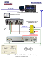
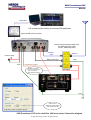
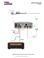
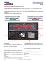
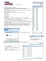
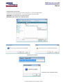
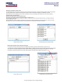
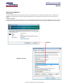
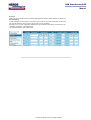
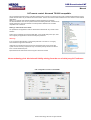
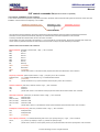
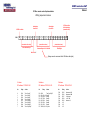
1
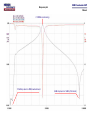
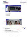
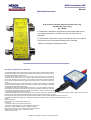
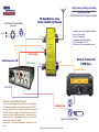
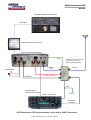
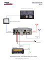
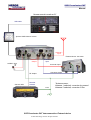
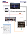
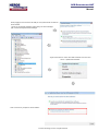
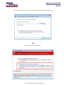
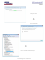
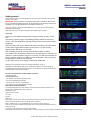
SCR Preselector-CAT
Tunable 1.8MHz to 50 MHz Software Controlled Radio preselector.
Featuring tracking operation from dedicated radio software.
User manual. Rev 02
© Heros Technology Ltd 2012. All rights reserved.
SCR Preselector-CAT
Manual
Features:
The SCR Preselector-CAT is suitable to work with SDR or analogue radios. It is inserted between the antenna and your receiver or transceiver providing
filtering of R.F.spectrum to reduce broadband energy and conforming signals before they reach the receiver, rejection of the MW AM broadcast band and VHF
FM broadcast band, removing strong emissions radiated back to the
antenna from quadrature mixers and attenuating signals in the VHF
region that could mix with the sampling frequency of the analog to
digital data converter in SDR radios.
IMPORTANT: If the preselector is connected in line with a
transceiver, take precautions to prevent transmitting through it. An
Input/Output power RF relay accessory is available to by-pass the
preselector in transmision switch-over.
The SCR Preselector-CAT can be operated in Stand-alone mode, via
USB from a personal computer, a software remote control application
console is provided for Windows (32 & 64 bits) operate systems, over
the Internet or from an external dedicated I2C controller.
Five control modes:
Stand-alone mode: by means of its control knobs.
Remote modes:
- Graphic User Interface (GUI). Remote console on PC.
- CAT serial protocol over Virtual Com Port (VCP), Kenwood TS-2000 protocol.
- Over the Internet or Local Network. (TCP/IP protocol).
- I2C bus from an external dedicated controller.
CAT remote control. Tracking feature
CAT (Computer Aided Transceiver), serial data communication protocol over Virtual Com Port (VCP) enables the SCR preselector-CAT to provide the user with
a way to interface with several radios. The SCR Preselector-CAT acts as a passive listener translating valid CAT commands into specific instructions.
Technical features:
■ Six selectable bands and preselector By-Pass.
■ FiveTuneable Band Pass Filter bank for HF Bands covering 1.8 to 30 MHz
plus 50MHz band BPF.
■ All filters are LC passive. No active switching or amplifier devices in the
signal path, (LNA Off), therefore it does not contribute to IMD (Intermodulation
Distortion).
■ Very high linearity (IP3). Suitable for Software Define Radios and analogue
receivers.
■ PTT feature enables connecting in-line with a 100Watts transceiver allowing
to by-pass the preselector in transmission. (with external Dual By-Pass relay
accessory)
■ Two antenna inputs, one antenna output, let insert a converter, filter, etc
between antenna and Preselector.
■ 0dB, 6dB, 12dB, 18dB input attenuator using MiniCircuits PAT series
dedicated attenuation cells.
■ Embedded -110dB stop band Broadcast Band Rejection Filter. (AKA BCB
filter, Brick Wall filter, MW band killer filter).
■ Six Band Pass Filters: ■ Tuning coils wound on large toroid cores T-106 size, rated for 100Watts RF applications, avoiding saturation in front of large signals.
■ Band Pass Filters have Notch filters centered on the adjacent amateur bands given an exceptional stop-band attenuation. (see graphic below)
■ Digital tuning. Nine bits variable digital capacitor. One pF resolution. (Variable capacitor emulator).
■ Two embedded 7th order, 60MHz, Elliptic Low Pas Filter for FM broadcast band rejection and sampling frequency attenuation.
■ Switchable low noise amplifier (LNA) 25dB Gain, 38dB IP3 , 2.7dB Noise Figure.
■ 12V DC/1Amp DC max. output connector for an external 150 Watts RF rating Input/Output by-pass dual power relay. (PTT or Keying line activated).
■ Power supply: 12Volts DC/ 1 Amp max. 2.5mm plug power connector.
■ Dimension: 220mm x165mm x 52mm (8.661 x 6.496 x 2.047in).
■ Weight: 1.5Kg
USB
■ Full speed USB v2.0 compliant.
■ Plug and Play feature.
■ USB type B connector.
■ ESD protection on USB lines.
■ Optional USB Galvanic Isolator available.
I2C bus
■ I2C bus external lines Galvanically isolated(ADuM1251).
■ 8 bits standard I2C serial bus interface.
■ Supports 100Kbits/s and 400kbits/s FAST I2C Bus protocol.
■ Mini Din connector for I2C control lines.
■ Compatible with most microcontrollers.
© Heros Technology Ltd. 2012. All rights reserved.
Response plot.
SCR Preselector-CAT
Manual
7.078MHz centre tuning
112dB stop band on MW broadcast band.
92dB stop band on 14MHz (20m band)
Encoders
Antenna 1
Input
LCD display
3 lines x 16 characters
BackLight
In Circuit Serial Programming
Service Connector
Bands
&
Function set
Gas Discharge Tube
Filtered
Tunning
&
Menu
12V DC output for by-pass RF power relay.
Stand-alone control mode
PTT
Keying line
Antenna 1
Output
Microcontroller
Filtered
USB remote from PC:
PIC 18F4550
Control/Data Bus
External Converter
Filter
Device
Graphic User Interface
CAT- VCP
TCP/IP
EMC / ESD
Protection
Amp
I2C bus external remote control
Antenna 2
Input
Stand-alone/USB/TCP-IP
control modes
Six BPF bank.
Five tunable Band Pass Filter
1.8MHz to 50MHz
Gas Discharge Tube
Control/Data Bus
I2C remote mode
2
1
3
4
Galvanic Isolator
Control/Data Bus
Control/Data Bus
I2C slaves
Relay power drivers
Preselector By-Pass
Preselector By-Pass
Control/Data Bus
Step Attenuator:
- 0dB
- 6dB
- 12dB
- 18dB
LNA By-Pass
BCB filter
60MHz 7 poles
Elliptic LPF
60MHz 7 poles
Elliptic LPF
Input attenuator
Preselector
Output
LNA
MW Broadcast band
rejection filter
Low Noise Amplifier
High gain: 20dB
High IP3:+38 dBm
Low noise figure:2.7dB
FM band rejection filter.
Sampling frequency attenuation.
9 bits/512pf digital variable capacitor
1pf resolution.
(Variable capacitor emulator)
SCR Preselector-CAT Diagram
50MHz band (no tunable BPF)
1.8-50MHz tunable Band Pass Filter bank.
SCR Preselector-CAT
Manual
1
2
3
1 - Dinamic LCD display.
2 - Function selector.
3 - Tunig/main menu.
1
2
3
4
5
6
7
8
9
10
1 - I2C bus remote control lines input. 4 ways MiniDin connector.
2 - USB connector. Type B.
3 - Input DC12V/500mA max. Power Jack 2.5mm connector.
+
4 - Earth post.
5 - RF output 50Ω. BNC connector.
6 - RF antenna 1 output 50Ω. BNC connector.
7 - DC output to external Antenna By-Pass relay, 12V DC/1Amp max.
8 - RF antenna 2 input, 50Ω. BNC connector.
9 - PTT/Keying line switch Input. Jack 3.5mm mono.13mA close to ground.
10 - RF antenna 1 input, 50Ω. BNC connector.
© Heros Technology Ltd 2012. All rights reserved.
+5V DC/5mA
SCL
2
1
Gnd
3
4
SDA
(Front view)
SCR Preselector-CAT
Manual
Optional Accessories
High Frequency General Purpose Dual By-Pass relay
150 Watts RF power rating
DC - 60MHz
A versatil device designed to by-pass the Input and Output RF ports of
any ancillary equipment connected in line with your transceiver or
transmitter.
On transmission switchover the Input and Output RF ports of any device
connected in line are by-passed avoiding being overloaded.
Switching configuration: default By-Passed.
USB Galvanic Digital Isolator for SDR radios
The USB Galvanic Digital Isolator for SDR radios is designed to break the galvanic connection between USB host
PC and the attached SDR radio peripheral avoiding that whatever power and ground noise from the PC side do
not influence the sensible radio on the other side.
The resultant galvanic isolation improves common-mode voltage, prevents ground loops, a common cause of
interference and data distortion issues, improves reception, as the noise floor in the receiver is lowered, and
removes spikes and birdies on the PC panoramic screen. In addition provides isolation of 1000V AC between the
host PC and the radio peripheral that guard against surges that may come from the antenna connected to the
receiver.
The USB Galvanic Digital Isolator for SDR radios is based on ADuM 4160 Full/Low Speed 5 kV USB Digital
Isolator and ADuM 5000 Isolated DC-to-DC Converter both from Analog Devices combining high speed CMOS
and chip-scale air transformer iCoupler technology.
The USB Galvanic Digital Isolator complies with specifications USB 1.1, Low speed (1.5Mbit/s) and USB 2.0 Full
Speed (12Mbit/s). The speed mode is set manually via two jumpers inside (default full speed). Most of the time it
is not necessary change between modes but if automatic speed detection is desired, an external hub can be
connected to the peripheral side configured for full speed.
The USB Galvanic Digital Isolator is self powered from the host PC through the USB cable. An embedded DC/DC converter provides a galvanic isolated voltage of 5VDC/100mA to the
peripheral side. It includes additionally ESD, EMC protection of the data lines and power transient short-circuit guard.
It is highly advisable not to power any part of the connected radio from the USB bus, instead an external dedicated power supply must be used.
The USB Galvanic Digital Isolator behaves like an USB cable, no USB drivers are needed. It works on all operating systems, Mac, Windows, Linux, etc.
Features:
Isolation 1.000 Volts AC
Protection: EMC, ESD, Overvoltage Surge, Short-circuits.
Power supply:
- PC side: From USB cable, 5VDC. Attached signalling LED.
- Drawn power from peripheral radio max: Through USB cable, 5V DC/100mA.
USB modes: Full speed (12 MBit/S) Low speed (1.5 MBit/S). Switchable.
Standard socket connectors: PC side: USB type B, peripheral side: USB type A.
Dimensions 67 mm x 66 mm x 28 mm. (2.638x2.598x 1.102inch)
USB2 pair of cables included
© HEROS technology Limited 2012. All rights reserved
High Frequency Dual By-Pass Relay
HF Dual By-Pass relay
model: Default By-Passed
Control line connectors wiring
By-passing example
SCR Preselector-CAT connection diagram.
(Front view)
12V DC
+
-
1
4
2
3
J1
J2
* Reception (relay is activated by Preselector)
- Ports J1-J2 connected
- Ports J4-J3 connected
* Transmission (relay NO activated)
- Port J3 connected to Port J1
- Ports J2 and J4 are connected to ground.
J5
Control cable
SCR Preselector-CAT
Antenna Input
J4
J3
Generic Transceiver
(150W max.)
Antenna Input
RF Output
WARNING TO AVOID DAMAGE THE UNIT!
In order to give enough time to the relays to switch before
the RF power signal outputs the transceiver when the PTT is
pressed, assure that your transceiver provides a delayed
"SEND" control line signal. Normally that control line is
present on Linear Amplifier connector. Also several transceivers feature a programmable delay, see the owners
manual of your particular radio.
Alternatively a Transmission/Reception Sequencer can be
used.
Switching line
Logic or manual switching
© HEROS technology Limited 2015. All rights reserved
SCR Preselector-CAT
Manual
Antenna 1
Input
RF Output
12VDC/500mA max.
Antenna 2
Input
+
-
Generic radio
Receiver
Antenna
Earth
SCR Preselector-CAT Interconnection. In line with a receiver. Stand-alone mode.
© Heros Technology Ltd 2012. All rights reserved.
SCR Preselector-CAT
Manual
Remote control console on PC
USB cable
Optional USB Galvanic isolator
Earth
150 Watts RF rating Input/Output
by-pass dual power relay.
(model: Default By-Pass)
Antenna 1
Input
12VDC/1 Amp
Antenna
+
-
RF Output
Relay control
Earth
PTT/Keying line
13mA close to ground
Generic Transceiver
Transceiver
Antenna
SCR Preselector-CAT interconnection. In line with a 100W Transceiver.
© Heros Technology Ltd 2012. All rights reserved.
SCR Preselector-CAT
Manual
Remote control console on PC
Optional USB Galvanic isolator
Antenna 1
Input
USB cable
RF Output
Antenna 2
Input
+12VDC/1 Amp.
Receiver
Antenna
Generic radio
Earth
SCR Preselector-CAT PC interconnection. In line with a receiver.
© Heros Technology Ltd 2012. All rights reserved.
SCR Preselector-CAT
Manual
Remote control console on PC
USB cable
Optional USB Galvanic isolator
Antenna 1
Input
External device: Converter
Antenna 1
Output
12VDC/1 Amp.
Antenna 2
Input
+
Converter Input
-
Converter Output
RF Output
Generic radio
Receiver
Antenna
Earth
*Antenna menu:
Antenna 1 selected, converter by-passed.
Antenna 2 selected, converter in line.
SCR Preselector-CAT Interconnection. External device
© Heros Technology Ltd 2012. All rights reserved.
SCR Preselector-CAT
PowerSDR on PC
Manual
CAT remote control (tracking)
Virtual COM port over USB
FireWire cable
NOTE:
No CAT utilities or COM port splitter software is needed.
Optional USB Galvanic isolator
RF Output
USB cable
Antenna ports
12VDC/1Amp
+
Antenna 1
Input
RX1 IN
(loop config)
-
Loop
Earth
(see Primary antenna ports configuration
on FLEX-5000_Owners_Manual)
RX1 OUT
(loop config)
SCR Preselector-CAT interconnection. FlexRadio.
© Heros Technology Ltd 2012. All rights reserved.
SCR Preselector-CAT
Manual
IEE 1394 cable
USB cable
CAT remote control tracking from PowerSDR application
Optional USB Galvanic isolator
USB cable
General Purpose Dual By-Pass relay
100 Watts RF power rating
(model: Default By-Pass)
Antenna
Antenna 1 Input
12VDC/1 Amp max
+
Relay control line
-
Earth
Preselector Output
Earth
PTT line
Flex 3000 Antenna port
IEE 1394 cable
Earth
Options Sub-Tab
Enable PTT Delay 100mS
(See Owners manual)
SCR Preselector-CAT in line with Flex 3000 transceiver. Connection diagram
© Heros Technology Ltd 2012. All rights reserved.
SCR Preselector-CAT
Manual
USB cable
CAT remote control tracking from PowerSDR application
Optional USB Galvanic isolator
General Purpose Dual By-Pass relay
100 Watts RF power rating
(model: Default By-Pass)
Antenna 1
Input
12VDC/1 Amp
+
Relay control line
-
Earth
Antenna
Earth
Preselector Output
FlexWire connector
Pin 3 PTT Out (13mA)
Pins 1-5 Ground
(See Owners manual)
Flex 1500 Antenna port
Earth
Earth
Antenna Form
Enable PTT Delay 100mS
(See Owners manual)
SCR Preselector-CAT in line with Flex 1500 transceiver. Connection diagram
© Heros Technology Ltd 2012. All rights reserved.
SCR Preselector-CAT
Manual
MiniDin 4 ways plug
solder side
+5VDC/5mA
2
SCL
1
3
4
Ferrite core
Gnd
from an external dedicated I2C controller.
SDA
Shield
Antenna 1
Input
RF Output
12VDC/1 Amp.
+
-
Antenna 2
Input
Earth
Receiver
Antenna
Generic radio
SCR Preselector-CAT interconnection. I2C bus mode.
© Heros Technology Ltd 2012. All rights reserved.
SCR Preselector-CAT.
Caveats and Recommendations
Important:
If the preselector is connected in line with a transceiver, take precautions to prevent transmitting through it in transmission switch-over.
In this regard a suitable RF by-pass relay accessory is available.
Copy the contents of the CD-ROM provided into your computer; do not execute software applications from CD-ROM.
Keep safe a back-up of the original calibration tables included on the CD-ROM.
Assure to use a reliable external power supply providing 12 Volts DC-1 Amp. preferable based transformed instead switching technology
in order to avoid noise.
Avoid using a rating power supply of 20-40Amp generally used to feed transceivers. They are designed to manage strong loads no low
current ancillary equipment.
Power first the power supply feeding the SCR Preselector-CAT, next switch on the power toggle switch located on rear panel,
no on the contrary.
Wait for a Power ON delay of around five seconds.
After switching off wait for several seconds before switch on again.
Avoid switch off suddenly the Preselector if it is connected to a computer via USB port. A data transaction may be is occurring, if so the microcontroller on board, computer software or USB port could be damage. Close or stop first the application running on the computer. For the same
reason avoid unplug suddenly the USB cable.
Caveats:
If you are working with Windows 7 and specially Windows 7 /64 bits O.S. it is highly recommended to upgrade to Windows 8.1
Computer COM ports are a limited resource and must be managed properly or your whole radio system could be severely compromised.
Any unnecessary activity should be avoided in favour of avoid saturate the COM ports.
Experimental/beta Radio Control Programs should be avoided.
Heros technology Limited disclaims all liability arising from the use of third party CAT software.
Installing Windows 8.1 USB Driver.
By default Windows 8.1 enforces driver signatures (covert taxation); in order to disable it:
Log on Windows as Administrator.
From the Metro or Desktop:
Bring up mouse over to the right side of the screen.
Go to Settings
Change PC Settings
General
Advanced Start-up > Restart Now
Trouble shoot > Advanced options
Start-up Settings
Restart the computer
New Blue Window: Start-up Settings/ 'Disable driver signature enforcement"/ press F7
Restart the computer.
Install the relevant driver, allowing to install on the non-signed driver message window.
SCR Preselector-CAT
Manual
When plugging for the first time to the USB port the system will ask for install the
driver software.
- Ignore the Found New Hardware window and go to Device Manager
path: Control Panel/System/Device Manager`.
- Rigth mouse button on Heros Tech.SCR Preselector-CAT 2012 and
click on Update Driver Software
- Click on Browse my computer for driver software
© Heros Technology Ltd 2012. All rights reserved.
SCR Preselector-CAT
Manual
Locate SCR Preselector CAT.inf file in the SCR Preselector-CAT Driver folder and click Next button.
Click on Install this driver software anyway.
© Heros Technology Ltd 2012. All rights reserved.
SCR Preselector-CAT
Manual
Installing driver software
Driver succesfully installed
A Virtual Com Port has been created over the USB port
© Heros Technology Ltd 2012. All rights reserved.
SCR Preselector-CAT
Manual
Getting started
Select among the above connection diagrams to set-up the SCR Preselector-CAT according
with your radio system.
IMPORTANT: If the preselector is connected in line with a transceiver, take precautions to prevent transmitting through it. An Input/Output power RF relay accessory is
available to by-pass the preselector in transmision switch-over.
Copy the contents of the provided CD-ROM into your computer, do not execute software
applications from CD-ROM.
Image 1
Keep safe a back-up of the original calibration tables folder on your computer.
Power Up.
Assure to use a reliable external power supply providing 12 Volts/ 1 Amp
DC.
Avoid using a power supply of 20-40Amp generally utilised to feed transceivers. They are designed to manage strong loads no low current ancillary
equipment.
Power first the power supply feeding the SCR Preselector-CAT, next switch
on the power toggle switch located on rear panel, no on the contrary.
Wait for Power ON delay of 5 seconds.
After switching off wait for several seconds before switch on again.
Avoid switch off suddenly the Preselector if it is connected to a computer via
USB port. A data transaction may be is occurring, if so the microcontroller on
board, computer software or USB port could be damage. Close or stop first
the application running on the computer.
For the same reason avoid unplug suddenly the USB cable.
Image 2
Image 3
Switching on the preselector, a welcome message is displayed. (Image 1)
Rotating the Function selector knob(2) the LCD display changes to main menu.(Image 2)
Image 4
By default Stand-alone mode if the USB cable from PC is detached. To change among modes
rotate and press Function selector knob(2)
They are five preselector control modes to choose:
- Stand-alone mode.
Through USB from PC:
- from Graphic User Interface application (GUI).
Image 5
- CAT from a dedicated radio software.
- TCP/IP from the Internet or Local Network.
- I2C mode from an external dedicated controller.
Stand-alone mode of operation
To navigate through the main menu rotate the Function selection knob(2) and press on the
desired option. Available options are: (Image 2-3)
Stand-alone mode.
Image 6
USB-CAT-TCP/IP mode.
I2C mode.
By-Pass.
Band A to F.
Each band has its own menu, rotate Function selector knob(2) to position the cursor on any
function press and release the knob to change options. (Image 4)
Band F, 50MHz band, is a non tunable BPF so no tune value is shown. (Image 5)
They are five memories available for each band. Each memory keeps all parameters shown on
display. (Image 6)
Image 7
To change to main menu press Tunig-main menu knob(3).
Attaching the USB cable from PC changes display accordly. Rotating the Function selection knob(2) the LCD display changes to main menu.(7)
© Heros Technology Ltd 2012. All rights reserved.
SCR Preselector-CAT
Manual
Graphic User Interface (GUI) on PC. Remote control console.
The SCR Preselector-CAT is commanded by the user by means of the GUI console on PC as it would in stand-alone mode.
The GUI context menu provides additional options and utilities.
The application console runs under Windows (32 & 64 bits) operate systems.
Open the SCR Preselector-CAT application; a pop-up window will emerge indicating the USB connection status. By default the
preselector application starts in by-pass state on power-on. In this state all controls are disabled except antenna selection and
context menu.
Available controls, options and utilities are itemised below.
13
12
11
80m
Beacon
1
10
2 3
4
5
6
7
1- Band selection.
Click over band push-button to change band or live By-pass state.
2- Input attenuator.
0dB, 6dB, 12dB, 18dB of attenuation available.
8
9
8- Tune Reference Dial. Displays the actual tuned frequency and
the corresponding capacitor value. Notice the attenuation of the pass
band filters increases with less capacity due to the response of series
tuned circuits.
9- Mnemonic text box. A brief caption can be written in the text
boxes. Five memories for each band can be stored, twenty-five in
total. On band change memories and captions are updated.
3- Low Noise Amplifier. LNA ON/OFF.
4- By-Pass.
By-passes the preselector. Default on power-on. In this state
all controls are disabled except antenna selection and contextual
menu.
5- Antenna selection. Two antenna input available. Active in by-pass
state.
6- Tuning step. x1, x2, x5, x10. Position x1 performs scan clicking on
the dial.
10- Memory management.
11- Frequency scale. Frequency references on the scale are
updated in accordance with the calibration tables.
12- Context menu.
Right mouse button click on dial or function key F2 opens the context
menu.
13- PTT pushed on.
7- Tuning knob.
Performs tuning rolling the mouse wheel. Also by pressing left or right
arrows on the keyboard. Adjust to maximum signal or background
noise.
© Heros Technology Ltd 2012. All rights reserved.
SCR Preselector-CAT
Manual
Context menu
Right mouse button click on dial window or function key F2 opens the
Context menu.
A set of program options are available to the user as follows:
Set Frequency. Function key F3
Enter any valid frequency expressed in MHz.
I2C slave s address. Function key F4
Internal I2C slaves address can be changed.
Useful when the preselector is working in I2C remote
control mode.
Notice that the Third address, bit A0, is always the
complementary value of Second address one. Address is
obtained automatically by software.
© Heros Technology Ltd. 2012. All rights reserved.
SCR Preselector-CAT
Calibration table
Write calibration tables. Function key F5
IMPORTANT: Keep safe a back-up of the calibration tables on your computer
Calibration tables are needed by the microcontroller on board to translate frequency CAT commands
into tune capacity values.
SCR Preselector-CAT comes calibrated from factory. Whenever the user can do recalibration with the
aid of the calibration tables for each band.
The SCR Preselector-CAT program folder contains five documents so-called
table_BAND_A.txt
table_BAND_B.txt
table_BAND_C.txt
table_BAND_D.txt
table_BAND_E.txt
table_BAND_F.txt
(Table_Band_F do not need be changed due it is a non tunable BPF)
The tables link the operating frequency with the tuning capacity value, comprised between 0 and 511
maximum. That value can be read on Tune Reference Dial (8)
The column on the left is the capacity value, on the right the frequency related in MHz.
With the aid of a reference frequency or receiver, values in the calibration tables can be modified. Up
to 64 reference points can be added to the list. Intermediate values in the table are computed by the
microcontroller on board.
To calibrate, tune the preselector at maximum reference frequency or background noise on your
receiver; enter in the table the capacity value shown in the Tune Reference Dial (8) and the reference
frequency from your RF generator or receiver dial. Frequency must be expressed in MHz.
Next, calibration tables must be updated into the microcontroller; function key F5 opens the
message box.
Updating calibration tables.
After update close the program and open again. The microcontroller on board
resets, starts again and reads the new calibration tables.
If writing tables a syntax error occurs a warning message is show when the program is open
again.
Logfile. Function key F6
A Logfile is generated each time that the SCR PreselectorCAT application is opened . It is helpful to diagnosis
purposes.
Function key F6 opens the Logfile.
Also the file can be found in the program folder as Log.txt.
© Heros Technology Ltd.. 2012. All rights reserved.
Manual
SCR Preselector-CAT
Manual
Firmware update. Function key F7
To update the on board microcontroller firmware, Function key F7 pops-up the dialog window.
Select SCR_CAT_Firmware20120422.v1_0_0_2.hex file, located in the program folder.
WARNING! Do not stop the process, wait until finished.
IMPORTANT: After update write calibration tables.
Updating the Firmware
Remember write calibration tables
© Heros Technology Ltd 2012. All rights reserved.
SCR Preselector-CAT
Manual
Internet/Local network remote control
The SCR Preselector-CAT supports connections via the Internet and Local network.To make use of this feature execute the application
on your computer and on a remote one.The protocol only uses TCP/IP; UDP which by definition is unreliable is not used.
Remember that you are accepting incoming TCP/IP connections so you must configure your firewall on your PC and on external
hardware firewall. See details below.
Remote server (preselector side) Function key F9
To start the communication open first the Remote Server, Function key F9 .
The connection console is displayed showing the address in dotted format of the computer where the server is running and the port
number, default port 51000.
Click on Start button. If the connection is successful you will start to receive commands from the client computer, current commands
are traced on the console. The SCR Preselector-CAT will respond in accordace with valid CAT commands.
Remote Server console
Receiving data from the Remote Client
Remote Client (remote control side) Function key F8
To connect to the server make sure the server is started and is listening. Open the Remote Client, Function key F8 .
The connection console is displayed showing the default address in dotted format of the host computer and the port number, default
port 51000. Enter the Host IP address in the text window and start operating the SCR Preselector-CAT application. Executed
commands on the GUI are traced on the console. Also valid CAT commands can be send from the text box.
192.168.1.3
Remote Client console
Sending data to the Remote Server
© Heros Technology Ltd 2012. All rights reserved.
SCR Preselector-CAT
Manual
Send CAT command. Function key F10
Let send valid CAT commands for testing purposes.
BU;
© Heros Technology Ltd 2012. All rights reserved.
SCR Preselector-CAT
Manual
Network Configuration
Public IP Address.
To make your SCR Preselector-CAT Remote server visible to the outside world you must have a public IP address; this is an address that is
reachable on the global Internet. Some ISP's assign public addresses which may change from time-to-time; this is known as a dynamic IP
address.
Firewall configuration
You must allow incoming TCP/IP connections on the port number selected in the Remote server's Console, by default this port number is 51000.
You may have more than one firewall activated on your router and Windows Firewall. If the Windows firewall is enabled then when you start the
SCR Preselector-CAT
Unblock
Windows Firewall
© Heros Technology Ltd 2012. All rights reserved.
SCR Preselector-CAT
Manual
Anti-virus.
Make sure you do not have anti-virus software inspecting and/or blocking TCP/IP traffic on the server port.
Port Forwarding
As well as allowing incoming TCP/IP connections on port 51000 you must route connections on this port to
the computer where the server is running, this is known as Port Forwarding.
Depending on your router configuration software this may be referred to as Firewall> Virtual Servers, Port
Forwarding, Forwarding - Virtual Servers,etc.
The screenshot below is from a Belkin router.
SCR Preselector-
© Heros Technology Ltd 2012. All rights reserved.
SCR Preselector-CAT
Manual
CAT remote control. Kenwood TS-2000 compatible.
CAT (Computer Aided Transceiver), serial data communication protocol over Virtual Com Port (VCP) enables SCR Preselector-CAT to
provide the user with a way to interface with several radios. The user can track the SCR Preselector-CAT from remote control software
applications.
Refer to your specific radio software application manual regarding CAT operation.
The SCR Preselector-CAT acts as a passive listener translating valid CAT commands into
specific instructions.The microcontroller on board performs valid Kenwood TS-2000
compatible CAT commands.
Starting in CAT remote control mode.
The preselector GUI application must be closed before interface with any remote control
software.
Power-On the preselector and plug the USB cable, a new virtual COM port is open; start
and configure your application to control remotely the preselector.
Warning:
If you are working with Windows 7 and specially Windows 7 /64 bits O.S. it is highly
recommended to upgrade to Windows 8.
COM ports are a limited resource and must be managed properly or the whole radio
system could be severely compromised. Any unnecessary activity should be avoided in
favor of avoid saturate the ports.
Experimental and/or beta Radio Control Programs should be avoided.
Heros technology Ltd. disclaims all liability arising from the use of third party CAT software.
CAT configuration console on PowerSDR
© Heros Technology Ltd 2012. All rights reserved.
SCR Preselector-CAT
Manual
CAT control commands list (Kenwood 2000 compatible)
CAT CONTROL COMMANDS. General information.
A CAT control command is composed of an alphabetical command, parameter, and the terminator that signals the end of the control command.
EXAMPLE: Command to set tune frequency to 14.250 MHz
Alphabetic command (prefix)
Parameter(11 digits)
Terminator (semicolon)
FA00014250000;
There are three command categories: Set (write) command that change preselector status, Get (read) command that request status
information from the preselector and Answer (response) command that return information requested in a Get command.
A correctly executed Set command does not return an Answer command.
The terminator for all CAT commands is the semicolon (;). CAT commands are not case sensitive. Get and Set commands must contain the
correct number of parameter characters as shown below. Get commands are simply the prefix followed by a termination.
SCR Preselector-CAT. Available CAT commands.
Band commands: prefix BNx (x band number, 1 digit ; ). SET commands
BN0;
By-Pass
BN1;
Band A
BN2;
Band B
BN3;
Band C
BN4;
Band D
BN5;
Band E
BU;
Band-up
ZZBU
(PowerSDR)
BD;
Band-down
ZZBD;
(PowerSDR)
BN;
(answer: BNx; where x is the band number) request information about Band status. GET command.
Frequency commands: prefix FA (band number, 11 digit ; ). frequency in Hz. SET commands.
FA000xxxxxxxx;
(e.g. 3.8MHz FA00003800000, e.g. 21.315MHz FA00021315000
ZZFA;
(PowerSDR)
FA;
(answer FA000xxxxxxxx;) request information about frequency status. GET command.
Antenna commands: prefix ANx (x antenna number, 1 digit ; ). SET commands.
AN1;
antenna 1.
AN2;
antenna 2
AN;
(answer ANx; where x is the antenna number) request information about antenna status. GET command.
Attenuator commands: prefix RAxx (xx attenuator number, 2 digit ; ). SET commands.
RA00;
attenuator 0dB
RA06; or RA01;
attenuator 6dB
RA12; or RA02;
attenuator 12dB
RA18; or RA03;
attenuator 18dB
RA;
(answer RAxx; where xx is the attenuator value) request information about attenuator status. GET command.
Preamplifier commands (LNA): prefix PAx (x antenna number, 1 digit ; ). SET commands.
PA0;
Preamplifier OFF
PA1;
Preamplifier ON
ZZPA;
(PowerSDR)
Tune capacity commands: ( non standard Kenwood) prefix CPxxx (xxx capacity value (pF.), 3 digit ; ). SET commands.
CPxxx;
(e.g. CP210; sey capacity to 210pF, e.g. CP009; set capacity to 9pF).
CP;
(answer CPxxx; where xxx is the capacity value in pF.) request information about tune capacity status. GET command.
© Heros Technology Ltd 2012. All rights reserved.
SCR Preselector-CAT
Manual
I2C bus remote control mode.
SCR Preselector-CAT features remote control mode from a dedicated external control system supporting I2C bus
data communications. It operates totally independent of other remote control modes.
External I2C bus master controller must implement the control software detailed in the table below.
I2C lines are Galvanically isolated by means of ADuM1251 a hot swappable digital isolator specialised device from
Analog Devices Inc.
I2C signal lines SDA, SCL, +12V and Ground from the I2C controller are connected to a 4 ways miniDin socket on
rear panel. Pinout cabling is shown below.
External I2C Bus lines
4 ways mini-Din socket connector pin-out
+5V DC/5mA
SCL
2
1
Gnd (isolated)
3
4
SDA
(Front view)
In order to switch to I2C remote control mode first program the I2C addresses on GUI, Context menu, I2C slave s
address (Function key F4).
Go to LCD main menu, Functions selection knob (2), and pick 3. I2C Mode . The preselector remains on that
remote control mode until other control mode is selected.
© Heros Technology Ltd 2012. All rights reserved.
SCR Preselector-CAT
Manual
I2C Bus remote control implementation
Writing sequence to slaves.
Acknoledge
from Slave
START condition
SDA
S
1
1
0
0
A2 A1 A0
0
0
0
STOP condition
NO Acknoledge
(controller ends)
Acknoledge
from Slave
1
0
0
0
1
0
0
0 P17 P16 P15 P14 P13 P12 P11 P10
P
(controller to slave)
(controller calls slave)
(controller to slave)
Slave Address Byte
Command Byte h 44 b 1000100
Data Byte
Write bit= 0
(Always send a command data h 44 before data byte.)
1st slave:
I2C address: 1100 A2 A1 A0
2nd slave:
I2C address: 1100 A2 A1 A0
3rd slave:
I2C address: 1100 A2 A1 A0
bit
Relay
Action
bit
Action
bit
Relay
Action
0
1
2
3
4
5
6
7
RL13
RL14
RL15
RL16
RL17
RL18
RL19
RL20
Tune Cap 1pF
Tune Cap 2pF
Tune Cap 4pF
Tune Cap 8pF
Tune Cap 16pF
Tune Cap 32pF
Tune Cap 64pF
Tune Cap 128pF
P10 - RL21
P11 - RL11, RL12
P12 - RL9, RL10
P13 - RL7, RL8
P14 - RL5, RL6
P15 - RL3, RL4
P16 - RL1, RL2
P17- RL23,24,30
Tune Cap 256pF
Band F
Band E
Band D
Band C
Band B
Band A
By-Pass
P00
P01
P02
P03
P04
P05
P06
P07
RL25
RL26
RL27
RL29
RL22
NC
NC
NC
Attenuator 6dB
Attenuator 12dB
LNA signal
+12V LNA
Antenna 1, 2
Relay
SCR Preselector-CAT
Manual
NOTES:
Heros technology Limited disclaims all liability arising from this information and its use.
It is your responsibility to ensure that your application meets with your specifications.
Information contained in this publication regarding device applications and the like is provided only for your convenience
and may be superseded by updates.
Heros technology Limited makes no representations or warranties of any kind whether express or implied, written or oral,
statutory or otherwise, related to the information, including but not limited to its condition, quality, performance,
merchantability or fitness for purpose.
© HEROS technology Limited 2012. All rights reserved