1
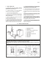
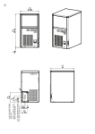
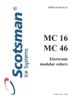
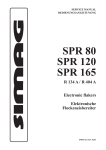
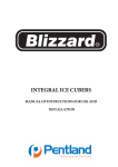
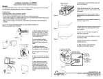
C
A
C
B
1
2
3
SDN 25 - 30
B
C
A
1
2
3
SDN 35 - 45 - 65
➊ CORD SET - ELEK. KABEL
➋ Ø 20 WATER OUTLET - WASSERABFLUSS
➌ G3/4" WATER INLET - WASSEREINLAUF
SDN 25 (mm)
SDN 30 (mm)
SDN 35 (mm)
SDN 45 (mm)
SDN 65 (mm)
A
334
377
377
485
485
B
454
552
552
572
572
C
597
637
637
721
816
Page 1
GENERAL INFORMATION
AND INSTALLATION
A.
INTRODUCTION
This manual provides the specifications and the
step-by-step procedures for the installation, startup and operation, maintenance and cleaning for
the SIMAG SDN Series Icemakers.
The SIMAG SDN cubers are quality designed,
engineered and manufactured.
Their ice making systems are thoroughly tested
providing the utmost in flexibility to fit the needs
of a particular user.
NOTE. To retain the safety and performance
built into this icemaker, it is important that
installation and maintenance be conducted
in the manner outlined in this manual.
B.
UNPACKING AND INSPECTION
1. Call your authorized SIMAG Distributor or
Dealer for proper installation.
2. Visually inspect the exterior of the packing
and skid. Any severe damage noted should be
reported to the delivering carrier and a concealed
damage claim form filled in subjet to inspection of
the contents with the carrier’s representative
present.
3. a) Cut and remove the plastic strip securing
the carton box to the skid.
b) Remove the packing nails securing the
carton box to the skid.
c) Cut open the top of the carton and remove
the polystyre protection sheet.
d) Pull out the polystyre posts from the
corners and then remove the carton.
9. Remove the manufacturer’s registration
card from the inside of the User Manual and fillin all parts including: Model and Serial Number
taken from the data plate.
Forward the completed self-addressed
registration card to SIMAG factory.
C.
LOCATION AND LEVELLING
WARNING. This Ice Maker is designed for
indoor installation only. Extended periods
of operation at temperature exceeding
the following limitations will constitute
misuse under the terms of the SIMAG
Manufacturer’s Limited Warranty resulting
in LOSS of warranty coverage.
1. Position the machine bin in the selected
permanent location and tighten the four legs
(SDN 35 - 45 - 65 - SD 80 - 125 - 210).
Criteria for selection of location include:
a) Minimum room temperature 10°C (50°F)
and maximum room temperature 40°C (100°F).
b) Water inlet temperatures: minimum 5°C
(40°F) and maximum 40°C (100°F).
c) Well ventilated location for air cooled
models (clean the air cooled condenser at
frequent intervals).
d) Service access: adequate space must be
left for all service connections through the rear of
the ice maker. A minimum clearance of 15 cm
(6") must be left at the sides of the unit for routing
cooling air drawn into and exhausted out of the
compartment to maintain proper condensing
operation of air cooled models.
5. Remove all internal support packing and
masking tape.
NOTE. With the unit in “built-in” conditions,
the ice production is gradually reduced in
respect to the levels shown in the graph, up
to a maximum of 10% at room temperatures
higher than 32°C.
The daily ice-making capacity is directly
related to the condenser air inlet temperature, water temperature and age of the machine.
To keep your SIMAG CUBER at peak performance levels, periodic maintenance checks
must be carried out as indicated on this
manual.
6. Check that refrigerant lines do not rub
against or touch other lines or surfaces, and that
the fan blades move freely.
2. Level the Icemaker in both the left to right
and front to rear directions by means of the
adjustable legs.
7. Check that the compressor fits snugly onto
all its mounting pads.
D.
4. Remove the front and the rear panels of the
unit and inspect for any concealed damage.
Notify carrier of your claim for the concealed
damage as stated in step 2 above.
8. See data plate on the rear side of the unit
and check that local main voltage corresponds
with the voltage specified on it.
CAUTION. Incorrect voltage supplied to
the icemaker will void your parts
replacement program.
ELECTRICAL CONNECTIONS
See data plate for current requirements to
determine wire size to be used for electrical
connections. All SIMAG icemakers require a
solid earth wire.
All SIMAG ice machines are supplied from the
factory completely pre-wired and require only
electrical power connections to the wire cord
provided at the rear of the unit.
Page 2
Make sure that the ice machine is connected to
its own circuit and individually fused (see data
plate for fuse size).
The maximum allowable voltage variation should
not exceed -10% and +10% of the data plate
rating. Low voltage can cause faulty functioning
and may be responsible for serious damage to
the overload switch and motor windings.
NOTE. All external wiring should conform to
national, state and local standards and
regulations.
Check voltage on the line and the ice maker’s
data plate before connecting the unit.
E.
WATER SUPPLY AND DRAIN
CONNECTIONS
GENERAL
When choosing the water supply for the cuber
consideration should be given to:
a) Length of run
b) Water clarity and purity
c) Adequate water supply pressure
Since water is the most important single ingredient
in producing ice you cannot emphasize too much
the three items listed above.
Low water pressure, below 1 bar may cause
malfunction of the ice maker unit.
Water containing excessive minerals will tend to
produce cloudy colored ice cubes, plus scale
build-up on the interior parts of the water system.
installed in an accessible position between the
water supply line and the unit.
If water contains a high level of impurities, it is
advisable to consider the installation of an
appropriate water filter or conditioner.
WATER SUPPLY - WATER COOLED MODELS
(SD 80-125-210)
The water cooled versions of SIMAG Ice Makers
require two separate inlet water supplies, one for
the water making the ice and the other for the
water cooled condenser.
Connect the 3/4" GAS male fitting of the water
inlet, using the flexible tubing supplied with the
unit, to the cold water supply line with regular
plumbing fitting and a shut-off valve installed in
an accessible position between the water supply
line and the unit.
WATER DRAIN
Connect the drain fitting with a plastic tube to an
open trapped and vented drain. When the drain
is a long run, allow 3 cm pitch per meter (1/4"
pitch per foot).
On water cooled versions, the water drain line
from the condenser is internally connected with
the drain fitting of the unit.
It is strongly recommended therefore to install a
vertical open vent on unit drain line high point to
ensure good draining and to direct the drain line
to a trapped and vented floor drain receptacle.
WATER SUPPLY
Connect the 3/4" GAS male of the water inlet
fitting, using the food grade flexible tubing supplied
with the machine, to the cold water supply line
with regular plumbing fitting and a shut-off valve
NOTE. The water supply and the water drain
must be installed to conform with the local
code. In some case a licensed plumber and/
or a plumbing permit is required.
Page 3
F. FINAL CHECK LIST
1. Is the unit in a room where ambient
temperatures are within a minimum of 10°C
(50°F) even in winter months?
2. Is there at least a 15 cm (6") clearance
around the unit for proper air circulation?
3. Is the unit level? (IMPORTANT)
4. Have all the electrical and plumbing
connections been made, and is the water supply
shut-off valve open?
7. Have the bolts holding the compressor down
been checked to ensure that the compressor is
snugly fitted onto the mounting pads?
8. Check all refrigerant lines and conduit lines
to guard against vibrations and possible failure.
9. Have the bin liner and cabinet been wiped
clean?
10. Has the owner/user been given the User
Manual and been instructed on the importance of
periodic maintenance checks?
5. Has the voltage been tested and checked
against the data plate rating?
11. Has the Manufacturer’s registration card been
filled in properly? Check for correct model and
serial number against the serial plate and mail
the registration card to the factory.
6. Has the water supply pressure been checked
to ensure a water pressure of at least 1 bar
(14 psi)? Open the shut-off valve and verify the
absence of water losses from the connections.
12. Has the owner been given the name and the
phone number of the authorized SIMAG Service
Agency serving him?
G.
INSTALLATION PRACTICE
1.
2.
3.
4.
5.
6.
7.
8.
9.
Hand shut-off valve
Water filter
Water supply line (flexible hose)
3/4" GAS male fitting
Vented drain
Open trapped vented drain
Drain fitting
Main switch
Power line
WARNING. This icemaker is not designed for outdoor installation and will not function in
ambient temperatures below 10°C (50°F) or above 40°C (100°F).
This icemaker will malfunction with water temperatures below 5°C (40°F) or above 40°C
(100°F).