1
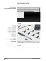
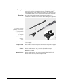
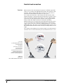
LOCKNUT-DOUBLEHOOK Double hook wrenches User manual Contents Page About the user manual General safety guidelines Scope of delivery Description Operation Symbols ................................................................................... 2 Availability ............................................................................... 2 Legal guidelines ....................................................................... 2 Original user manual................................................................. 2 Usage for the intended purpose ................................................ 3 Usage not for the intended purpose .......................................... 3 Qualified personnel .................................................................. 3 Hazards .................................................................................... 3 Protective equipment................................................................ 3 Safety specifications................................................................. 4 ................................................................................................ 5 Accessories .............................................................................. 6 Damage during transit............................................................... 6 Defects..................................................................................... 6 Overview .................................................................................. 7 Function ................................................................................... 8 Preparation............................................................................... 9 Mounting of parts ..................................................................... 14 Locating the shaft ..................................................................... 15 Setting of clearance .................................................................. 15 Decommissioning ................................................................................................ 20 Maintenance Maintenance plan ..................................................................... 21 Disposal Regulations .............................................................................. 21 Technical data and accessories ................................................................................................ 22 Appendix Conversion ............................................................................... 23 Schaeffler Technologies BA 28 1 Double hook wrenches About the user manual Symbols WARNING NOTICE Availability NOTICE Legal guidelines Original user manual 2 BA 28 This user manual is part of the device and contains important information. The warning and hazard symbols are defined in accordance with ANSI Z535.6-2006. In case of non-compliance, death or serious injury may occur. In case of non-compliance, damage or malfunctions in the product or the adjacent construction will occur. This user manual is supplied with each device and can also be ordered retrospectively. Damage to the bearing to be mounted since information that is important for correct adjustment is missing as a result of a user manual that is incomplete, illegible or missing. As the safety coordinator, you must ensure that this user manual is always complete and legible and that any persons using the device have the user manual available. The information in this manual corresponded to the most recent status at the close of editing. The illustrations and descriptions cannot be used as grounds for any claims relating to devices that have already been delivered. Schaeffler Technologies AG & Co. KG accepts no liability for any damage or malfunctions if the device or accessories have been modified or used in an inappropriate manner. The original user manual is taken to be a user manual in the German language. A user manual in another language is to be taken as a translation of the original user manual. Schaeffler Technologies General safety guidelines Usage for the intended purpose It describes how the device may be used, who may use the device and what must be observed when using the device. A double hook wrench with a torque wrench and mounting lever is used for its intended purpose when it is used to set radial internal clearance during the mounting of self-aligning ball bearings and spherical roller bearings with a tapered inner ring on an adapter sleeve. Usage not for the intended purpose The torque wrench must not be used to loosen tightened connections. It must not be used as an impact tool. Usage not for the intended purpose can lead to injury or damage. Qualified personnel The double hook wrench, torque wrench and mounting lever may only be used by qualified personnel. A person defined as qualified personnel: ■ has all the necessary knowledge ■ is aware of all the hazards and safety guidelines ■ has been authorised to use the double hook wrench, torque wrench and mounting lever by the safety co-ordinator ■ has fully read and understood this user manual. Hazards Protective equipment Schaeffler Technologies If a tool is damaged, it may break when subjected to load. For this reason, only an undamaged tool may be used and repairs to the tool are prohibited. Personal protective equipment is intended to protect operating personnel against health hazards. This comprises safety shoes, safety gloves and protective goggles and these must be used in the interests of personal safety. BA 28 3 Double hook wrenches Safety specifications Transport Storage Operation Maintenance Disposal Conversion 4 BA 28 The following safety specifications must be observed when using the double hook wrench, torque wrench and mounting lever. Further guidelines on hazards and specific operating procedures can be found, for example, in section Operation, page 9. If the ambient conditions during transport of the tool differ to a large extent from the ambient conditions specified for its use, the tool must not be used immediately. The double hook wrench, torque wrench and mounting lever must always be stored under the ambient conditions described. These ambient conditions are as follows: ■ humidity max. 90%, non-condensing ■ no aggressive chemicals in the environment ■ temperature from +5 °C to +40 °C. Unsuitable ambient conditions may result in corrosion of the double hook wrench, torque wrench and mounting lever. The double hook wrench, torque wrench and mounting lever may only be used under the ambient conditions described. These ambient conditions are as follows: ■ humidity max. 70%, non-condensing ■ no aggressive chemicals in the environment ■ temperature from +15 °C to +25 °C ■ brightness at least 500 Lux. Unsuitable ambient conditions may result in health hazards to the operating personnel. Only original replacement parts may be used. Regular maintenance must be carried out on the torque wrench. Locally applicable regulations must be observed. The double hook wrench, torque wrench and mounting lever must not be converted. Schaeffler Technologies Scope of delivery Scope of delivery Double hook wrench set LOCKNUT-DOUBLEHOOK-KM3-8-SET The scope of delivery comprises the double hook wrench, torque wrench, mounting lever, transport case, mounting paste and user manual, see table and Figure 1 as well as table and Figure 2, page 6. m1) Component Designation Torque wrench LOCKNUT-DOUBLEHOOK.WRENCH10-50NM 1,1 Double hook wrench LOCKNUT-DOUBLEHOOK-KM3-D16 0,2 LOCKNUT-DOUBLEHOOK-KM4-D16 0,2 LOCKNUT-DOUBLEHOOK-KM5-D16 0,2 LOCKNUT-DOUBLEHOOK-KM6-D16 0,2 LOCKNUT-DOUBLEHOOK-KM7-D16 0,2 LOCKNUT-DOUBLEHOOK-KM8-D16 0,3 Mounting lever LOCKNUT-DOUBLEHOOK.LEVER400 0,8 Transport case LOCKNUT-DOUBLEHOOK.CASE-KM3-8 3 Mounting paste ARCANOL-MOUNTINGPASTE-70G 0,1 User manual MATNR 032821409-0000 – kg 1) Mass. � Torque wrench WRENCH10-50NM � Double hook wrench KM3 � Double hook wrench KM4 � Double hook wrench KM5 � Double hook wrench KM6 � Double hook wrench KM7 � Double hook wrench KM8 � Mounting lever � Transport case �� Mounting paste �� User manual Schaeffler Technologies 00019B86 Figure 1 Scope of delivery Double hook wrench set KM3-8 BA 28 5 Double hook wrenches Scope of delivery Double hook wrench set LOCKNUTDOUBLEHOOK-KM9-15-SET m1) Component Designation Torque wrench LOCKNUT-DOUBLEHOOK.WRENCH20-100NM 2,3 Adapter LOCKNUT-DOUBLEHOOK.WRENCH-ADAPTER22-16 0,1 Double hook wrench LOCKNUT-DOUBLEHOOK-KM9-D20 0,4 LOCKNUT-DOUBLEHOOK-KM10-D20 0,4 LOCKNUT-DOUBLEHOOK-KM11-D20 0,4 LOCKNUT-DOUBLEHOOK-KM12-D20 0,4 LOCKNUT-DOUBLEHOOK-KM13-D20 0,4 LOCKNUT-DOUBLEHOOK-KM14-D20 0,4 LOCKNUT-DOUBLEHOOK-KM15-D20 0,4 Mounting lever LOCKNUT-DOUBLEHOOK.LEVER400 0,8 Transport case LOCKNUT-DOUBLEHOOK.CASE-KM9-15 3 Mounting paste ARCANOL-MOUNTINGPASTE-70G 0,1 User manual MATNR 032821409-0000 – kg 1) Mass. � Torque wrench � Adapter � Double hook wrench KM9 � Double hook wrench KM10 � Double hook wrench KM11 � Double hook wrench KM12 � Double hook wrench KM13 � Double hook wrench KM14 � Double hook wrench KM15 �� Mounting lever �� Transport case �� Mounting paste �� User manual Accessories Damage during transit Defects 6 BA 28 00019B87 Figure 2 Scope of delivery Double hook wrench set KM9-15 Individual parts are supplied without accessories. For accessories such as mounting paste, see section Technical data and accessories, page 22. Any damage during transit must be reported as a complaint to the carrier. Any defects must be reported promptly to Schaeffler Technologies AG & Co. KG. Schaeffler Technologies Description The method described in this manual, in conjunction with the appropriate tool, can be used to achieve precise setting of the radial internal clearance of self-aligning ball bearings and spherical roller bearings without the need to measure the radial internal clearance. Overview Reduction of the radial internal clearance requires the use of a double hook wrench, torque wrench and mounting lever, Figure 3. 0001A1BF � Double hook wrench � Marking of torsion angle � Hole for locking pin � Torque wrench � Adapter � Locking pin � Mounting lever Figure 3 Tool Double hook wrench This is made from steel and is marked with values for standardised torsion angles. Torque wrench This is made from steel and plastic and must be subjected to regular maintenance. Adapter This is made from steel and is used to change the locating diameter. The adapter is supplied already fitted to the torque wrench WRENCH20-100NM. Mounting lever Schaeffler Technologies This is made from steel and can be inserted in the double hook wrench in the same way as the torque wrench. BA 28 7 Double hook wrenches Function Measurement of the radial internal clearance is difficult especially in the case of smaller self-aligning ball bearings and spherical roller bearings. If the bearing is fitted in a housing, it is not possible to measure the radial internal clearance in some cases. As a result, measurement is often dispensed with and the radial internal clearance is estimated in approximate terms by means of the method normally used in the past. In this case, the rolling bearing is pressed onto the adapter sleeve until the outer ring can still be freely rotated and slight resistance is felt under swivelling. With the method we recommend, the radial internal clearance can be set very accurately. The radial internal clearance is reduced in two stages, Figure 4. First, the locknut is lightly tightened to a specified tightening torque. This gives a precisely defined initial position and the radial internal clearance is then set very accurately in the second stage. The locknut is then tightened by a defined angle. The radial internal clearance has now been reduced by the recommended 60% to 70%. Figure 4 Reducing the radial internal clearance 8 BA 28 00019B88 � Housing � Self aligning ball bearing � Adapter sleeve � Locknut � Double hook wrench � Torque wrench � Mounting lever � Radial internal clearance, locknut lightly tightened � Radial internal clearance, locknut completely tightened Schaeffler Technologies Operation Preparation Schaeffler Technologies Mounting is carried out at a suitable location: ■ sufficiently strong illumination ■ ergonomic working height for the fitter. The torque wrench may only be used if it has been subjected to correct maintenance, see section Maintenance, page 21. Based on the bearing to be mounted, the tool to be used and the tightening torque to be applied can be determined from the tables, see table, page 11. NOTICE Incorrect friction value due to contamination. This leads to in correct setting of the bearing radial internal clearance and thus wear of the bearing. Clean the parts to be mounted thoroughly using a lint-free cloth. NOTICE Damage to the bearing during dismounting if the locknut has cold welded to the adapter sleeve. Apply a thin coating of mounting paste to the thread of the adapter sleeve, for example using ARCANOL-MOUNTINGPASTE-70G. BA 28 9 Double hook wrenches Preparing the tool and parts NOTICE Before mounting, the tool and the parts to be mounted must be prepared, Figure 5: ■ double hook wrench fitted to the torque wrench ■ tightening torque set on the torque wrench ■ cleaned using a lint-free cloth: – bore and end faces of the bearing inner ring, the part of the shaft on which the adapter sleeve will be mounted, adapter sleeve ■ thin coating of mounting paste applied to the thread of the adapter sleeve. Danger of injury if the double hook wrench becomes detached from the torque wrench or mounting lever. Ensure that the locking pin fully engages when the double hook wrench is attached. Figure 5 Tool and parts to be mounted 10 BA 28 0001A3AF � Double hook wrench � Locking pin engaged � Torque wrench � Display of tightening torque � Bearing inner ring � Shaft � Adapter sleeve Schaeffler Technologies Self-aligning ball bearings Tools, values Schaeffler Technologies Designation Nut of LOCKNUT-DOUBLEHOOKadapter Double Torque wrench sleeve hook wrench Tightening Torsion torque angle Nm ° 1203-K KM3 KM3-D16 WRENCH10-50NM 10 – 2203-K KM3 KM3-D16 WRENCH10-50NM 10 – 1303-K KM3 KM3-D16 WRENCH10-50NM 16 – 2303-K KM3 KM3-D16 WRENCH10-50NM 16 – 1204-K KM4 KM4-D16 WRENCH10-50NM 14 – 2204-K KM4 KM4-D16 WRENCH10-50NM 14 – 1304-K KM4 KM4-D16 WRENCH10-50NM 24 – 2304-K KM4 KM4-D16 WRENCH10-50NM 24 – 1205-K KM5 KM5-D16 WRENCH10-50NM 23 – 2205-K KM5 KM5-D16 WRENCH10-50NM 22 – 1305-K KM5 KM5-D16 WRENCH10-50NM 42 – 2305-K KM5 KM5-D16 WRENCH10-50NM 18 30 1206-K KM6 KM6-D16 WRENCH10-50NM 36 – 2206-K KM6 KM6-D16 WRENCH10-50NM 34 – 1306-K KM6 KM6-D16 WRENCH10-50NM 37 30 2306-K KM6 KM6-D16 WRENCH10-50NM 33 30 1207-K KM7 KM7-D16 WRENCH10-50NM 34 30 2207-K KM7 KM7-D16 WRENCH10-50NM 31 30 1307-K KM7 KM7-D16 WRENCH10-50NM 40 45 2307-K KM7 KM7-D16 WRENCH10-50NM 49 30 1208-K KM8 KM8-D16 WRENCH10-50NM 22 60 2208-K KM8 KM8-D16 WRENCH10-50NM 20 60 1308-K KM8 KM8-D16 WRENCH10-50NM 41 60 2308-K KM8 KM8-D16 WRENCH10-50NM 32 60 BA 28 11 Double hook wrenches Self-aligning ball bearings Tools, values (continued) 12 BA 28 Designation Nut of adapter sleeve LOCKNUT-DOUBLEHOOKDouble hook wrench Torque wrench Tightening Torsion torque angle 1209-K KM9 KM9-D20 WRENCH20-100NM 27 60 2209-K KM9 KM9-D20 WRENCH20-100NM 36 60 1309-K KM9 KM9-D20 WRENCH20-100NM 65 60 2309-K KM9 KM9-D20 WRENCH20-100NM 57 60 1210-K KM10 KM10-D20 WRENCH20-100NM 27 60 2210-K KM10 KM10-D20 WRENCH20-100NM 35 60 1310-K KM10 KM10-D20 WRENCH20-100NM 77 60 2310-K KM10 KM10-D20 WRENCH20-100NM 64 60 1211-K KM11 KM11-D20 WRENCH20-100NM 22 60 2211-K KM11 KM11-D20 WRENCH20-100NM 21 60 1311-K KM11 KM11-D20 WRENCH20-100NM 66 60 2311-K KM11 KM11-D20 WRENCH20-100NM 43 60 1212-K KM12 KM12-D20 WRENCH20-100NM 45 60 2212-K KM12 KM12-D20 WRENCH20-100NM 44 60 1312-K KM12 KM12-D20 WRENCH20-100NM 60 75 2312-K KM12 KM12-D20 WRENCH20-100NM 70 60 1213-K KM12 KM12-D20 WRENCH20-100NM 36 75 2213-K KM12 KM12-D20 WRENCH20-100NM 25 75 1313-K KM13 KM13-D20 WRENCH20-100NM 92 75 2313-K KM13 KM13-D20 WRENCH20-100NM 60 75 1214-K KM14 KM14-D20 WRENCH20-100NM 38 75 2214-K KM14 KM14-D20 WRENCH20-100NM 47 75 1314-K KM14 KM14-D20 WRENCH20-100NM 52 90 2314-K KM14 KM14-D20 WRENCH20-100NM 100 75 1215-K KM15 KM15-D20 WRENCH20-100NM 59 75 2215-K KM15 KM15-D20 WRENCH20-100NM 66 75 1315-K KM15 KM15-D20 WRENCH20-100NM 98 90 2315-K KM15 KM15-D20 WRENCH20-100NM 75 90 Nm ° Schaeffler Technologies Spherical roller bearings Tools, values Schaeffler Technologies Designation Nut of adapter sleeve LOCKNUT-DOUBLEHOOKDouble hook wrench Torque wrench Tightening Torsion torque angle 22205-K KM5 KM5-D16 WRENCH10-50NM 18 30 22306-K KM5 KM5-D16 WRENCH10-50NM 35 75 22307-K KM5 KM5-D16 WRENCH10-50NM 35 21304-K KM5 KM5-D16 WRENCH10-50NM 24 – 21305-K KM5 KM5-D16 WRENCH10-50NM 42 – 22206-K KM6 KM6-D16 WRENCH10-50NM 33 30 21306-K KM6 KM6-D16 WRENCH10-50NM 40 30 22207-K KM7 KM7-D16 WRENCH10-50NM 24 60 21307-K KM7 KM7-D16 WRENCH10-50NM 26 60 22208-K KM8 KM8-D16 WRENCH10-50NM 34 60 21308-K KM8 KM8-D16 WRENCH10-50NM 27 75 22308-K KM8 KM8-D16 WRENCH10-50NM 35 75 22209-K KM9 KM9-D20 WRENCH20-100NM 51 60 21309-K KM9 KM9-D20 WRENCH20-100NM 25 90 22309-K KM9 KM9-D20 WRENCH20-100NM 70 75 22210-K KM10 KM10-D20 WRENCH20-100NM 62 60 21310-K KM10 KM10-D20 WRENCH20-100NM 53 90 22310-K KM10 KM10-D20 WRENCH20-100NM 96 75 22211-K KM11 KM11-D20 WRENCH20-100NM 44 75 21311-K KM11 KM11-D20 WRENCH20-100NM 19 90 22311-K KM11 KM11-D20 WRENCH20-100NM 68 75 22212-K KM12 KM12-D20 WRENCH20-100NM 38 85 21312-K KM12 KM12-D20 WRENCH20-100NM 51 90 22312-K KM12 KM12-D20 WRENCH20-100NM 67 85 22213-K KM13 KM13-D20 WRENCH20-100NM 82 85 21313-K KM13 KM13-D20 WRENCH20-100NM 91 90 22313-K KM13 KM13-D20 WRENCH20-100NM 59 100 22214-K KM14 KM14-D20 WRENCH20-100NM 62 100 21314-K KM14 KM14-D20 WRENCH20-100NM 98 100 22314-K KM14 KM14-D20 WRENCH20-100NM 88 100 22215-K KM15 KM15-D20 WRENCH20-100NM 87 100 21315-K KM15 KM15-D20 WRENCH20-100NM 78 115 22315-K KM15 KM15-D20 WRENCH20-100NM 85 110 Nm ° 75 BA 28 13 Double hook wrenches Once all the parts to be mounted have been cleaned and a thin coating of mounting paste has been applied to the thread of the adapter sleeve, the parts can be mounted. Inserting and greasing the seals: Press the lower halves of the seals finger tight into the housing and grease the space between the seal lips. Place the shaft at the required position and lift it up. 0001A1C2 Mounting of parts � Housing � Shaft � Seal, lower half Figure 6 Seal 0001A1C3 While sliding the bearing onto the shaft, ensure that the adapter sleeve remains at the required position. Mounting the adapter sleeve and bearing: Slide the adapter sleeve to the required position on the shaft. Slide the bearing onto the adapter sleeve. � Housing � Shaft � Adapter sleeve � Required position of adapter sleeve � Bearing Figure 7 Adapter sleeve and bearing 14 BA 28 Schaeffler Technologies 00019B8C The tab washer should lie against the end face of the bearing inner ring. The locknut should lie lightly against the tab washer. Mounting the tab washer and locknut: Slide the tab washer onto the adapter sleeve. Screw the locknut onto the adapter sleeve. Lower the shaft. The bearing and adapter sleeve are mounted. The tab washer and locknut are mounted. � Housing � Shaft � Adapter sleeve � Bearing � Tab washer � Locknut � Shaft, lowered Figure 8 Tab washer and locknut Locating the shaft Setting the clearance Schaeffler Technologies The shaft must not be allowed to rotate during mounting. Before the shaft is located using a suitable retaining device, the corresponding area must be degreased. The following accessories are required: ■ retaining device for locating the shaft ■ retaining gib for preventing co-rotation of the adapter sleeve ■ waterproof felt pen for marking the position on the shaft. BA 28 15 Double hook wrenches Tightening the locknut to the tightening torque NOTICE During tightening, it may be necessary to reposition the double hook wrench several times. Locknut tightened to the incorrect torque due to incorrect hand position. This leads to incorrect setting of the bearing radial internal clearance and thus increased wear of the bearing. Use the torque with the correct hand position as shown. The centre of the grip must be located between the ring finger and middle finger. Tightening the locknut to the tightening torque, Figure 9: Locate the adapter sleeve by means of the retaining gib. Tighten the locknut until the torque wrench is released. The locknut is now tightened to the tightening torque. Figure 9 Tightening torque 16 BA 28 00019B8D � Adapter sleeve � Retaining gib � Locknut � Double hook wrench � Torque wrench � Marking of grip centre � Hand position Schaeffler Technologies Marking of components Before marking the components, the double hook wrench is removed from the torque wrench. The double hook wrench is then fitted to the mounting lever. The locknut and adapter sleeve are marked before the locknut is tightened by the torsion angle. A waterproof felt pin is highly suitable for applying the marking. Marking of components, Figure 10: Position the double hook wrench. At the mark for the angle 0, draw a line across the end faces of the locknut and the adapter sleeve. At the mark for the torsion angle, draw a line across the end faces of the locknut. The components are marked. 00019B8E � Mark for angle 0 � Mark for torsion angle Figure 10 Marking Schaeffler Technologies BA 28 17 Double hook wrenches Tightening the locknut by the torsion angle The clearance is set by tightening the locknut by the torsion angle. Tightening the locknut by the torsion angle, Figure 11: Locate the adapter sleeve by means of the retaining gib. Tighten the locknut until the mark for the torsion angle on the locknut and the mark for the angle 0 on the adapter sleeve coincide. The locknut is completely tightened and the clearance is set. Figure 11 Clearance set 18 BA 28 00019B92 � Adapter sleeve � Retaining gib � Locknut � Double hook wrench � Mark for angle 0 on adapter sleeve � Mark for torsion angle on locknut Schaeffler Technologies Securing the locknut NOTICE The locknut is secured against rotation in order that the clearance set cannot change during operation. Increased clearance in the bearing due to backwards rotation of the locknut, leading to increased wear of the bearing. Never loosen the locknut, but tighten it slightly as necessary. 00019B90 Securing the locknut, Figure 12: If there is no tab opposite a slot: tighten the locknut slightly. Bend the tab of the tab washer into the slot in the locknut. The locknut is secured against rotation. � Tab, bent over Figure 12 Locknut secured Schaeffler Technologies BA 28 19 Double hook wrenches Decommissioning NOTICE If the tool is no longer in use, the double hook wrench is removed from the mounting lever. Grease and any other contaminants should be wiped off the double hook wrench, mounting lever and torque wrench. Damaged torque wrench due to storage with preload. This leads to incorrect setting of the bearing radial internal clearance and thus increased wear of the bearing. Set the tightening torque to the value 0, Figure 13. 00019B93 � Torque wrench � Tightening torque 0 Figure 13 Decommissioning All parts should be stored under the specified conditions, see section Storage, page 4. 20 BA 28 Schaeffler Technologies Maintenance NOTICE Maintenance plan Before every use As necessary Disposal WARNING Regulations Schaeffler Technologies The tool must be checked before every use. Incorrect release of torque wrench due to lack of maintenance. This leads to incorrect setting of the bearing radial internal clearance and thus increased wear of the bearing. Check the torque wrench as stated in the maintenance plan and carry out maintenance as necessary. The maintenance items are stated in the maintenance plan, see tables. Subassembly Activity Torque wrench ■ Visual inspection – check for damage ■ Record the number of instances of use Double hook wrench, mounting lever ■ Visual inspection – check for damage Subassembly Activity Torque wrench ■ After 5 000 instances of use, carry out checking, maintenance as necessary and calibration The inspection device to be used must fulfil the requirements in DIN EN ISO 6789:2003 The tool can be returned to Schaeffler for disposal. Danger of injury due to catapulting of components if the torque wrench is dismantled, since some parts are under spring loading. Wear safety goggles if the torque wrench is to be dismantled. Disposal must be carried out in accordance with locally applicable regulations. BA 28 21 Double hook wrenches Technical data and accessories Torque wrenches Double hook wrenches Mounting levers Adapters Accessories Technical data, standard accessories and special accessories, see tables. Designation Dimensions Mass mm kg LOCKNUT-DOUBLEHOOK.WRENCH10-50NM 30⫻30⫻330 1,1 LOCKNUT-DOUBLEHOOK.WRENCH20-100NM 40⫻40⫻375 2,3 Designation Dimensions Mass mm kg LOCKNUT-DOUBLEHOOK-KM3-D16 111⫻41⫻26 0,2 LOCKNUT-DOUBLEHOOK-KM4-D16 111⫻44⫻26 0,2 LOCKNUT-DOUBLEHOOK-KM5-D16 111⫻50⫻26 0,2 LOCKNUT-DOUBLEHOOK-KM6-D16 111⫻60⫻26 0,2 LOCKNUT-DOUBLEHOOK-KM7-D16 111⫻70⫻26 0,2 LOCKNUT-DOUBLEHOOK-KM8-D16 112⫻78⫻26 0,3 LOCKNUT-DOUBLEHOOK-KM9-D20 117⫻83⫻30 0,4 LOCKNUT-DOUBLEHOOK-KM10-D20 117⫻88⫻30 0,4 LOCKNUT-DOUBLEHOOK-KM11-D20 117⫻98⫻30 0,4 LOCKNUT-DOUBLEHOOK-KM12-D20 117⫻106⫻30 0,4 LOCKNUT-DOUBLEHOOK-KM13-D20 117⫻115⫻30 0,4 LOCKNUT-DOUBLEHOOK-KM14-D20 118⫻121⫻30 0,4 LOCKNUT-DOUBLEHOOK-KM15-D20 118⫻128⫻30 0,4 Designation Dimensions Mass mm kg LOCKNUT-DOUBLEHOOK.LEVER400 ⭋22⫻400 0,8 Designation Dimensions Mass mm kg LOCKNUT-DOUBLEHOOK.WRENCH-ADAPTER22-16 ⭋22⫻40 0,1 Designation Designation Mass ARCANOL-MOUNTINGPASTE-70G Mounting paste kg 0,1 Only use FAG original accessories. 22 BA 28 Schaeffler Technologies Conversion This appendix contains conversion formulae for using a torque wrench not supplied by us. The following symbols are used in the formula, Figure 14. 0001A1C4 Appendix Figure 14 Conversion Torque to be set MA2 Nm Torque set on torque wrench Nm MA Tightening torque, see tables from page 11 l1 mm Distance between centre of locking pin and centre of grip l2 mm Key dimension, see certificate for torque wrench. Schaeffler Technologies BA 28 23 Notes 24 BA 28 Schaeffler Technologies MATNR 083667768-0000 / BA 28 / GB-D / 201308.5 / Printed in Germany by wünsch Schaeffler Technologies Every care has been taken to ensure the AG & Co. KG correctness of the information contained Postfach 1260 in this publication but no liability can be 97419 Schweinfurt accepted for any errors or omissions. Germany We reserve the right to make technical Georg-Schäfer-Straße 30 97421 Schweinfurt Germany changes. © Schaeffler Technologies AG & Co. KG Issued: 2013, August Phone +49 2407 9149-99 Fax +49 2407 9149-59 This publication or parts thereof may not E-mail [email protected] be reproduced without our permission. Internet www.schaeffler.com/services BA 28 GB-D