1
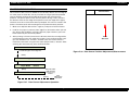
SERVICE MANUAL
Color Large Format Inkjet Printer
EPSON Stylus PRO 7000
®
SEIJ99017
Notice:
All rights reserved. No part of this manual may be reproduced, stored in a retrieval system, or transmitted in any form or by any means,
electronic, mechanical, photocopying, recording, or otherwise, without the prior written permission of SEIKO EPSON CORPORATION.
The contents of this manual are subject to change without notice.
All efforts have been made to ensure the accuracy of the contents of this manual. However, should any errors be detected, SEIKO EPSON
would greatly appreciate being informed of them.
The above not withstanding SEIKO EPSON CORPORATION can assume no responsibility for any errors in this manual or the consequences
thereof.
EPSON is a registered trademark of SEIKO EPSON CORPORATION.
General Notice: Other product names used herein are for identification purpose only and may be trademarks or registered trademarks of
their respective owners. EPSON disclaims any and all rights in those marks.
Copyright © 2000 SEIKO EPSON CORPORATION. Printed in Japan.
PRECAUTIONS
Precautionary notations throughout the text are categorized relative to 1) personal injury and 2) damage to equipment.
DANGER
Signals a precaution which, if ignored, could result in serious or fatal personal injury. Great caution should be
exercised in performing procedures preceded by DANGER Headings.
WARNING
Signals a precaution which, if ignored, could result in damage to equipment.
The precautionary measures itemized below should always be observed when performing repair/maintenance procedures.
DANGER
1. ALWAYS DISCONNECT THE PRODUCT FROM THE POWER SOURCE AND PERIPHERAL DEVICES PERFORMING ANY
MAINTENANCE OR REPAIR PROCEDURES.
2. NO WORK SHOULD BE PERFORMED ON THE UNIT BY PERSONS UNFAMILIAR WITH BASIC SAFETY MEASURES AS DICTATED
FOR ALL ELECTRONICS TECHNICIANS IN THEIR LINE OF WORK.
3. WHEN PERFORMING TESTING AS DICTATED WITHIN THIS MANUAL, DO NOT CONNECT THE UNIT TO A POWER SOURCE UNTIL
INSTRUCTED TO DO SO. WHEN THE POWER SUPPLY CABLE MUST BE CONNECTED, USE EXTREME CAUTION IN WORKING ON
POWER SUPPLY AND OTHER ELECTRONIC COMPONENTS.
WARNING
1. REPAIRS ON EPSON PRODUCT SHOULD BE PERFORMED ONLY BY AN EPSON CERTIFIED REPAIR TECHNICIAN.
2. MAKE CERTAIN THAT THE SOURCE VOLTAGES IS THE SAME AS THE RATED VOLTAGE, LISTED ON THE SERIAL NUMBER/
RATING PLATE. IF THE EPSON PRODUCT HAS A PRIMARY AC RATING DIFFERENT FROM AVAILABLE POWER SOURCE, DO NOT
CONNECT IT TO THE POWER SOURCE.
3. ALWAYS VERIFY THAT THE EPSON PRODUCT HAS BEEN DISCONNECTED FROM THE POWER SOURCE BEFORE REMOVING OR
REPLACING PRINTED CIRCUIT BOARDS AND/OR INDIVIDUAL CHIPS.
4. IN ORDER TO PROTECT SENSITIVE MICROPROCESSORS AND CIRCUITRY, USE STATIC DISCHARGE EQUIPMENT, SUCH AS ANTISTATIC WRIST STRAPS, WHEN ACCESSING INTERNAL COMPONENTS.
5. REPLACE MALFUNCTIONING COMPONENTS ONLY WITH THOSE COMPONENTS BY THE MANUFACTURE; INTRODUCTION OF
SECOND-SOURCE ICs OR OTHER NONAPPROVED COMPONENTS MAY DAMAGE THE PRODUCT AND VOID ANY APPLICABLE
EPSON WARRANTY.
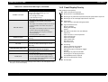
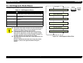
About This Manual
This manual describes basic functions, theory of electrical and
mechanical operations, maintenance and repair procedures of
EPSON EPSON Stylus PRO 7000. The instructions and procedures
included herein are intended for the experienced repair
technicians, and attention should be given to the precautions on
the preceding page.
Contents
CHAPTER 6. MAINTENANCE
Provides preventive maintenance procedures and the
lists of Epson-approved lubricants and adhesives
required for servicing the product.
CHAPTER 7. APPENDIX
Provides the following additional information for reference:
Connector pin assignments
This manual consists of six chapters and Appendix.
Parts list
CHAPTER 1. PRODUCT DESCRIPTIONS
Electric circuit boards components layout
Provides a general overview and specifications of the product.
CHAPTER 2. OPERATING PRINCIPLES
Describes the theory of electrical and mechanical operations of the
product.
CHAPTER 3. TROUBLESHOOTING
Provides the step-by-step procedures for the troubleshooting.
CHAPTER 4. DISASSEMBLY AND ASSEMBLY
Describes the step-by-step procedures for disassembling and
assembling the product.
CHAPTER 5. ADJUSTMENTS
Provides Epson-approved methods for adjustment.
Exploded diagram
Electrical circuit boards schematics
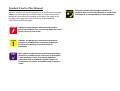
Symbols Used in This Manual
Various symbols are used throughout this manual either to provide
additional information on a specific topic or to warn of possible
danger present during a procedure or an action. Be aware of all
symbols when they are used, and always read WARNING,
CAUTION or NOTE messages.
W A R N IN G
Indicates an operating or maintenance procedure,
practice or condition that, if not strictly observed, could
result in injury or loss of life.
C A U T IO N
Indicates an operating or maintenance procedure,
practice, or condition that, if not strictly observed,
could result in damage to, or destruction of,
equipment.
C H E C K
P O IN T
May indicate an operating or maintenance procedure,
practice or condition that is necessary to accomplish
a task efficiently. It may also provide additional
information that is related to a specific subject, or
comment on the results achieved through a previous
action.
Indicates a reassembly procedure, practice, or
condition that, if not strictly adhered to, could result
in damage to, or nonoperability of, the equipment.
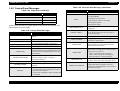
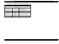
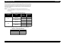
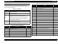
Revision Status
Revision
Issued Date
Rev. A
February 17, 2000
Rev. B
April 12, 2000
Description
First Release
Improved interface description (pg 31), nozzle check description (pg 43), paper thickness
detection (pg 46), cutter replacement (pg 47), maintenance mode 2 description (pg 50),
transportation mode (pg54)
Fixed illustrations on pages 60, 61, 63, 71
Fixed paper sensor volume adjustment
Added parts list and lubrication points
Added troubleshooting information regarding proper gap between cap and printhead
Added troubleshooting information regarding the cutter housing and encoder sensor
EPSON Stylus Pro 7000
Revision B
Contents
Chapter 1 Product Description
Features ...................................................................................................... 12
Consumable Products & Options ........................................................ 13
Standard Accessories ......................................................................... 13
Print Specifications ............................................................................... 14
Printing Specifications........................................................................ 14
Character Specifications..................................................................... 14
Paper Feeding ..................................................................................... 14
Paper Specifications ............................................................................. 15
Roll Paper Specifications.................................................................... 15
Cut Sheet Specifications .................................................................... 16
Printable Area ....................................................................................... 17
Ink Cartridges ........................................................................................ 18
Electrical Specifications ....................................................................... 18
Reliability ............................................................................................... 19
Environmental Conditions ................................................................... 19
Temperature/Humidity ....................................................................... 19
Vibration & Shock ............................................................................... 20
Controller .............................................................................................. 20
Conformity/Safety Approvals .............................................................. 21
Acoustic Noise ...................................................................................... 21
CE Marking ............................................................................................ 22
Interfaces .................................................................................................... 22
Parallel Interface - Compatibility Mode .............................................. 23
Data Transmission Timing ................................................................. 23
Parallel Interface - Nibble Mode .......................................................... 26
Parallel interface - ECP mode .............................................................. 27
USB ........................................................................................................ 29
TYPE-B Optional Interface ................................................................... 30
Preventing Data Transfer Time-Outs .................................................. 30
Interface Selection ................................................................................ 31
Physical Specifications ............................................................................. 32
Printer Dimensions & Weight ............................................................ 32
Setup Guidelines ................................................................................ 32
Cutter Specifications .......................................................................... 33
Control Panel ............................................................................................. 34
Buttons ................................................................................................ 34
LED indicators ..................................................................................... 35
Indicator Status in Normal Mode ........................................................ 36
Control Panel Messages ...................................................................... 37
Panel Display Priority ........................................................................... 38
Loading Paper ............................................................................................ 39
SelecType Settings ................................................................................... 40
Printer Setting Menu ............................................................................ 41
Test Print Menu .................................................................................... 42
Printer Status Menu ............................................................................. 44
Paper Configuration Settings .............................................................. 44
Cutter Replacement Menu ................................................................... 45
Head Alignment Menu ......................................................................... 46
Maintenance Request ............................................................................... 47
Service Requests ....................................................................................... 48
Maintenance And Diagnostic Modes .................................................. 49
Maintenance Mode ............................................................................. 49
Maintenance Mode 2 .......................................................................... 50
Self-Diagnostic Mode ......................................................................... 51
Firmware Update ...................................................................................... 51
Jumper Settings ........................................................................................ 52
Initialization ............................................................................................... 52
Transportation Mode ................................................................................ 53
7
EPSON Stylus Pro 7000
Chapter 2 Operating Principles
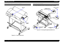
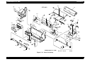
Component List & Illustrations ................................................................ 55
Print Mechanism Components ............................................................ 55
EPSON Stylus Pro 7000 Body & Stand ............................................. 57
Carriage Components......................................................................... 57
Paper Feed Path & Components........................................................ 58
Ink System Components .................................................................... 59
Electrical Circuit Boards ..................................................................... 59
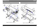
Description of Components ...................................................................... 60
Carriage Movement .............................................................................. 60
Carriage & Carriage Components ..................................................... 61
Paper Feed Assembly ........................................................................... 63
PF Rail .................................................................................................. 63
Paper-Feeding-Related Sensors ........................................................ 64
Maintenance Assembly ........................................................................ 65
CR Lock Mechanism ............................................................................. 66
Ink Supply Mechanism ......................................................................... 67
Ink-Related Sensors ............................................................................ 67
Printer Mechanism Operation Outline .................................................... 69
Carriage Mechanism ............................................................................ 69
Platen Gap Mechanism ...................................................................... 70
Paper Feed Mechanism ...................................................................... 72
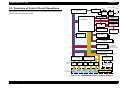
Summary of Control Circuit Operations ................................................. 76
Power Supply Board Summary ........................................................... 78
Chapter 3 Troubleshooting
Outline ........................................................................................................ 80
First... ..................................................................................................... 80
Remember ............................................................................................. 80
Diagnosing the Problem ...................................................................... 80
Maintenance Errors .............................................................................. 81
Service Errors ....................................................................................... 82
Troubleshooting Using the Error Messages ........................................... 83
Warnings ............................................................................................. 85
Errors ................................................................................................... 86
Fatal Errors .......................................................................................... 92
Revision B
Errors That Require a Service Technician ............................................... 93
Maintenance Call 0100 ....................................................................... 93
Service Call 00000100......................................................................... 93
Service Call 00000101......................................................................... 93
Service Call 00010000......................................................................... 93
Service Call 00010001......................................................................... 94
Service Call 00010002......................................................................... 94
Service Call 00010003......................................................................... 94
Service Call 00010004......................................................................... 95
Service Call 00010005......................................................................... 95
Service Call 00010006......................................................................... 96
Service Call 00010007......................................................................... 96
Service Call 00010008......................................................................... 96
Service Call 00010009......................................................................... 97
Service Call 0001000A ........................................................................ 97
Service Call 0001000B ........................................................................ 97
Service Call 0001000C ........................................................................ 97
Service Call 0001000D
Service Call 0001000E ........................................................................ 97
Service Call 0001000F......................................................................... 97
Service Call 00010010......................................................................... 97
Service Call 00020000 (NVRAM error)
Service Call 00020001 (Internal RAM error)
Service Call 00020002 (SRAM error)
Service Call 00020003 (DRAM error) ................................................. 98
Service Call 0002000B (Mail box Memory Error) ............................. 98
Service Call 10020004 (CPU gnrl illegal Instrctns)
Service Call 10020006 (CPU Slot illegal Instrctns)
Service Call 10020009 (CPU address error)
Service Call 1002000A (CPU DMAC/DTC address error)
Service Call 1002000B (CPU watchdog time-out error)
Service Call 100200## (CPU Vector 32~63)....................................... 98
General Errors ............................................................................................ 99
Ink Low ................................................................................................ 99
Paper Out............................................................................................. 99
Load xxx Paper ................................................................................. 100
Load Paper ........................................................................................ 100
Paper Jam ......................................................................................... 100
Cover Open ....................................................................................... 100
Paper Not Cut .................................................................................... 101
8
EPSON Stylus Pro 7000
Paper Not Straight ............................................................................ 101
Reload Paper ..................................................................................... 101
Please Lower Lever........................................................................... 102
Ink Out................................................................................................ 102
No Ink Cartridge ................................................................................ 102
Remove Paper ................................................................................... 103
Option I/F Error.................................................................................. 103
Troubleshooting Based on Your Printout ............................................. 103
Dot Missing ....................................................................................... 103
Uneven Printing/Poor Resolution .................................................... 104
Smudged or Marred Printout (Front) .............................................. 105
Smudged or Marred Printout (Reverse side).................................. 105
White or Black Banding .................................................................... 105
Chapter 4 Disassembly & Assembly
Summary .................................................................................................. 107
Warnings ............................................................................................. 108
Tools .................................................................................................... 110
Screw List ............................................................................................ 111
Disassembly Flow .................................................................................... 112
Removing the Housing ...................................................................... 113
Circuit Board Removal ....................................................................... 122
Printer Mechanism Disassembly ....................................................... 125
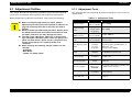
Chapter 5 Adjustment
Adjustment Outline ................................................................................. 157
Adjustment Tools ............................................................................... 157
Adjustment Items ............................................................................... 158
Adjustment Steps .................................................................................... 159
Parameter Backup .............................................................................. 159
Requirements for parameter Backup .............................................. 159
Backing up parameters From Main Board to PC card ................... 160
Downloading Parameters From PC Card to new Board ................ 160
Backup/Download Error Recovery................................................... 161
Range of Backed Up Parameters ..................................................... 161
Firmware Update ................................................................................ 162
Revision B
Updating Firmware Via the PC ........................................................ 162
Updating Firmware From a Memory Card ..................................... 163
Self-Diagnostics ....................................................................................... 164
Self-Diagnostic Mode Menus .................................................................
Test Menu ...........................................................................................
Version...............................................................................................
Control Panel.....................................................................................
Sensors ..............................................................................................
Sensor Adjustment ...........................................................................
Encoder..............................................................................................
Fan .....................................................................................................
Elec.....................................................................................................
D/A Revision and Head Signal .........................................................
Adjustment Menu ...............................................................................
Adj Cap Position ...............................................................................
Adj Check Skew ................................................................................
Write D/A Value.................................................................................
Adj Input Rank...................................................................................
Adj Check Nozzle ..............................................................................
Adj x Head Slant (B/C heads) ...........................................................
Adj B/C Head Height .........................................................................
Adj Bi-D..............................................................................................
Head Gap Adjustment ......................................................................
Flush Point adjustment ....................................................................
Feed Adjustment...............................................................................
Adj Top & Bottom .............................................................................
Adj Rear Sensor Position .................................................................
Test Pattern Print ..............................................................................
Clean Head (drain ink) ......................................................................
Counter Clear ....................................................................................
Cleaning Menu ...................................................................................
Print Menu ..........................................................................................
Parameter Menu .................................................................................
"Initialize" Items ................................................................................
"Update" Items ..................................................................................
165
166
167
167
168
169
172
172
172
173
174
176
176
177
177
178
179
181
183
187
188
189
190
191
192
193
194
194
195
195
195
195
Mechanism Adjustment .........................................................................
CR Timing Belt Tension Adjustment ...............................................
PF Timing Belt Tension Adjustment................................................
P THICK Sensor Assembly Adjustment ..........................................
197
198
198
199
9
EPSON Stylus Pro 7000
Revision B
Cover Open Sensor Assembly......................................................... 200
USB ID Copy/Backup .............................................................................. 201
Extracting the USB-ID Copy Program ............................................. 201
After Extracting the Program ........................................................... 201
Running the Program ......................................................................... 202
Copying the ID to the New Board.................................................... 202
Generating New ID & Writing It to the New Board ........................ 202
Chapter 6 Maintenance
General Maintenance Issues .................................................................. 204
Periodic Maintenance Items .............................................................. 206
Product Life Information .................................................................... 206
Important Maintenance Items During Service Operations ............. 207
Lubrication and Glue .......................................................................... 207
Chapter 7 Appendix
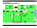
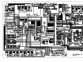
Wiring Diagrams ...................................................................................... 209
Parts List ................................................................................................... 211
Exploded View Diagram ......................................................................... 215
Component Layout .................................................................................. 226
Circuit Diagrams ...................................................................................... 228
10
CHAPTER
1
PRODUCT DESCRIPTION
EPSON Stylus Pro 7000
Revision B
Paper Save feature searches for the front edge of the roll paper before
1.1 Features
printing to make sure no paper at the leading edge is wasted
The EPSON Stylus Pro 7000 is an 24-inch wide, 6-color ink jet printer with
professional color output. It has the same printheads as the EPSON Stylus Pro
9000. The EPSON Stylus Pro 7000 provides the following major features and
more.
Large Format
Complete Software Compatibility With EPSON Stylus Pro 9000
Latest RIP Technology
CPSI Pro (software)
PS Server
Large format, yet provided as a desktop printer (optional stand
A1, full size
24 inch-full size printing (A1+size supported)
available)
Paper Handling:
Excellent Photo-quality printing
Standard roll paper feeder
1440 (H) x 720 (V) dpi combined with EPSON’s Microdot printing
Same quality as the EPSON Stylus Pro 9000.
Straight paper path
High-speed throughput
Automatic paper cutter
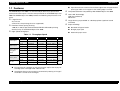
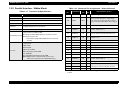
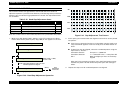
Table 1-1. Throughput Speed
EPSON media
Slide Bar
Resolution
Dot
Mode
Bi-D 200cps
Speed
Speed
360x360dpi
Normal 2 Dot
6 min.
Quality
360x360dpi
Normal Dot x 2 Bi-D FOL 300cps
8 min.
Presentation
Matte Paper
Speed
720x360dpi
Normal Dot
Bi-D FOL 300cps
8 min.
Quality
720x360dpi
Normal Dot
Uni-D FOL 300cps 14 min.
Glossy Photo
Semigloss
Photo
Speed
720x360dpi
Normal Dot
Bi-D FOL 300cps
8 min.
Quality
720x720dpi
Normal Dot
Bi-D FOL 300cps
15 min.
Adv. Photo
1440x720dpi
Micro Dot
Bi-D 4P 300cps
30 min.
720x720dpi
Micro Dot
Bi-D FOL 300cps
1440x720dpi
Micro Dot
Bi-D 4P 300cps
(Max.
A3+)
720x720dpi
Normal Dot
1440x720dpi
Micro Dot
Uni-D FOL 300cps (Max.
Uni-D 4P 300cps A2)
Plain Paper
Photo Quality Quality
Glossy Film
Adv. Photo
Photo Quality Quality
Ink Jet
Adv. Photo
Low running cost
Six separate ink cartridges so you only have to replace the empty ink
cartridge (each cartridge holds 110ml of ink)
Auto Rotate feature saves paper by automatically rotating an image if
the width is shorter than the height
Product Description
Features
12
EPSON Stylus Pro 7000
Revision B
1.1.1 Consumable Products & Options
Table 1-2. Consumables & Options (continued)
Name
Table 1-2. Consumables & Options
Name
Ink cartridges
Code
T460
T463
T462
T461
T465
T464
Product
Black Ink
Cyan Ink
Magenta Ink
Yellow Ink
Light Cyan Ink
Light Magenta Ink
Code
Product
Multi-protocol
Ethernet interface
card
C82362
Type-B 10Base-T
100Mbps Multiprotocol Ethernet
interface card
C82363
Type-B 100Base-T
IEEE 1394 interface
card
C82372
IEEE 1394 interface card
Stand
C844022
Optional stand
Paper cutter blade
C815131
Consumable item
Roll Feed Spindle 2”
C811092
For two-inch diameter roll paper
Roll Feed Spindle 3”
C811102
For three-inch diameter roll paper
STANDARD ACCESSORIES
Glossy Photo Paper
S041225
610mm (24 in.) wide/20.7m long
The following are standard accessories with the SP 7000:
Semigloss Photo
Roll Paper
S041223
24 in wide/25m long
Presentation Matte
Roll Paper
S041220
Photo Paper
S041142
S041143
S041156
A3
A3 Wide/B
B
Photo Quality Glossy
Film
S041073
S041074
S041075
A3
A3 Wide/B
B
Rip Station 5100 PS
Server Series II
EAI - C850092
Other - C850093
Product Description
Ink cartridges x6, one for each color
24 in wide/25m long
A2
A3
A3 Wide/B
B
Software RIP (CPSI
Pro)
Power cord x1
Roll paper spindle (2”) x1
S041079
S041068/S041045
S041069/S041043
S041070/S041044
Photo Quality Ink Jet
Paper
Note:
* Signifies a number that varies by market.
Printer driver utility set x1
Roll paper sample x1 (24” semi-gloss Photo roll paper 5m)
Roll paper fixing belt x1
Paper cutter x1
User’s manual set x1
Fiery Adobe® PostScript® 3™
Server
Software RIP (CPSI Pro)
Features
13
EPSON Stylus Pro 7000
Revision B
1.1.2 Print Specifications
CHARACTER SPECIFICATIONS
PRINTING SPECIFICATIONS
Control codes
ESC/P Raster
EPSON Remote command
Drop-On-Demand MACH (Multi-layer Actuator Head) inkjet - E-MACH
type
Character tables (2 international sets)
Nozzle configuration
64 nozzles per color (same printhead as the EPSON Stylus Pro 9000)
Print direction = Bi-direction (high-speed return, high-speed skip only)
PC 437 (US, Standard Europe)
PC 850 (Multilingual)
Typeface
Bitmap LQ font: EPSON Courier 10 CPI
Print Speed and Printable Area
Character mode
PAPER FEEDING
Character pitch
10cpi (Pica)
Printable area
237 characters
Printing speed
200 cps (one print-pass in which 1/2 of character
matrix is printed at 360dpi: 2pass)
Graphic mode
Table 1-3. Print Area and Speed
Horizontal resolution
(dpi)
Printable area
Max. printable dots
360
604mm
23.78 inches
8561
720
604mm
23.78 inches
17,123
30 IPS/FOL
30 IPS/4pass
1440
604mm
23.78 inches
34,246
20 IPS/FOL
30 IPS/4pass
Product Description
Paper feeding method:
Friction feed
Line spacing:
1/6” or programmable at 1/720”
Paper path:
Roll paper/manual
Feed speed:
1/6” 200±10m seconds
Continuous 2.5” (63.5mm)/second
Speed
20 IPS
Features
14
EPSON Stylus Pro 7000
Revision B
1.1.3 Paper Specifications
paper from the core
*3: At the point where the rear edge comes free from the core (approx.
last 30 cm.), print quality is no longer guaranteed.
*4: If a 3” core is used, the EPSON-exclusive optional 3” roll paper spindle
is required
ROLL PAPER SPECIFICATIONS
C A U T IO N
Paper must have no wrinkles, tears, or folds plus the surface
should be smooth.
EPSON Special Roll Paper
The following special papers meet or exceed EPSON requirements, and
paper feeding plus printout quality are assured.
Table 1-4. EPSON Special Paper
Minimum-Quality Roll Paper
Type (US)
Paper meeting the requirements described below can be used with this
printer, but neither the feeding nor printout quality is guaranteed.
•Size =
Width
Length
•Roll Size =
max.
Type (outside US)
Presentation Matte Presentation Matte
Paper
Paper
210~610mm
(8.4~24.0”)
279mm~90m (within roll size)
(11.1”~298.8’)
Paper Size
(W x H)
610mm x 25m
(24” x 83’)
610mm x 20.7m
(24” x 68.7’)
2” or 3” core (with optional 3” spindle) 150mm ext. diameter
Glossy Paper-Heavy
Glossy Photo Paper
Weight
210mm (same as A4)
x 10m
(8.4” x 33.2’)
329mm (same as
A3+) x 10m
(13.1” x 33.2’)
•Thickness = 0.08~0.5mm (0.003~0.019”)
Normal-Quality Roll Paper
For paper meeting the following requirements, the feeding operation only
is guaranteed.
Semi Glossy PaperHeavy Weight
Semigloss Photo
Paper
610mm x 25m
(24” x 83’)
•Size =
Photo quality glossy
Film (TBD)
Photo quality
glossy Film (TBD)
610mm x TBD
(24” x TBD)
Width
Length
•Roll Size =
max.
Roll Size
210~610mm
(8.4~24.0”)
279mm~90m (within roll size)
(11.1”~30’)
2” or 3” core (with optional 3” spindle) 150mm ext. diameter
2” core,
maximum103mm
external diameter
*1: Use at normal room temperature (15~25°C (59~77°F) 40~60%
humidity)
*2: At the point where the rear edge comes free from the core (approx.
last 30 cm.), print quality is no longer guaranteed.
•Thickness = 0.08~0.11mm (0.003~0.0043”)
•Weight = 64~90gf/m2 (17~24 lb.s)
•Quality = Normal paper, recycled paper
*1: Use at normal room temperature (15~25°C (59~77°F) 40~60%
humidity)
*2: The printer exerts between 300~500gf to peel off the rear edge of roll
Product Description
Features
15
EPSON Stylus Pro 7000
Revision B
Plain paper
CUT SHEET SPECIFICATIONS
C A U T IO N
For paper meeting the following requirements, only the feeding operation
is guaranteed.
Paper must have no wrinkles, tears, or folds plus the surface
should be smooth
•Size = see Table 1-5 above (plus the following requirements)
•Thickness = 0.08~0.11mm (0.003~0.0044”)
•Weight = 64~90gf/m2 (17~24 lb.s)
•Quality:
Paper must be fed short-edge first (portrait)
Use at normal room temperature (15~25°C (59~77°F)
40~60% humidity)
Minimum-quality paper
Normal, recycled paper
*1: Load short edge first (portrait)
*2: Use at normal room temperature (15~25°C (59~77°F) 40~60%
humidity)
EPSON Special Paper
Paper meeting the requirements described below can be used with this
printer, but neither the feeding nor printout quality is guaranteed.
The following special papers meet or exceed EPSON requirements, and
paper feeding plus printout quality are assured.
Size = see the following table
•Size = see the following table
Table 1-5. Supported Cut-Sheet Paper
Thickness =
Size
Dimensions (W x H)
B2
515 x 728mm
A1+
Table 1-6. Cut-Sheet Availability
Size
Dimensions
(W x H)
SuperFine
*1
PhotoPrint
Photo Quality
Glossy Film
Art
Board
24 x 36”
A4
210 x 297mm
Yes
Yes
Yes
-
A1
594 x 841mm
A3
297 x 420mm
Yes
Yes
Yes
-
A2
420 x 594mm
A3+
329 x 483mm
Yes
Yes
Yes
-
A3+
329 x 483mm
A2
420 x 594mm
Yes
-
-
-
A3
297 x 420mm
Letter
216 x 279mm
Yes
Yes
Yes
-
A4
210 x 297mm
B
279 x 432mm
Yes
Yes
Yes
-
ANSI D
22 x 34”
C
431 x 558mm
Yes
-
-
-
ANSI C
17 x 22”
B2
515 x 728mm
-
-
-
Yes
ANSI B
11 x 17”
Letter
8.5 x 11”
Table note:
*1: Print quality optimized with uni-direction printing
0.08~1.5mm (for 297~728mm/ 11.8~29.0” length paper
(0.003~0.06”)
0.08~0.5mm (for 728~915mm/ 29.0~36.4” length paper)
(0.003~0.02”)
Product Description
Features
16
EPSON Stylus Pro 7000
Revision B
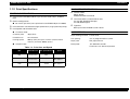
1.1.4 Printable Area
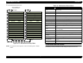
Table 1-7. Printable Area
PW
LM
RM
TM
Heading
Roll Paper
Cut Sheets
PW (width)
210 ~ 610mm
(8.27 ~ 24”)
210 ~ 610mm
(8.27 ~ 24”)
PL (length)
Max. 90m
(298.8’)
297~915mm
(11.8~36.4”)
LM (left margin)
3mm/15mm*
(0.12~0.59”)
3mm
TM (top)
3mm/15mm*
3mm
RM (right)
3mm/15mm*
3mm
BM (bottom)
3mm/15mm*
14mm
Note: *The size of the margin is determined by the control panel setting.
Paper
Feed
Printable Area
There are three margin settings via the control panel;
3mm = All margins are set to 3mm
15mm = All margins are set to 15mm
T/B 15mm TM and BM are 15mm, while LM and RM are
3mm
PL
Table 1-8. Optimal Margin Settings
BM
To optimize for
Select this setting
largest printable area and decrease chance of paper
rubbing printheads
Top/Bottom 15mm
exact paper size and decrease chance of paper rubbing
printheads
15mm
largest printable area and exact paper size
3mm
When the Paper Set Lever is:
Back
Figure 1-1. Printable Area
The feed path is open and you can load, remove or change the
position of paper in the feed path.
Forward
The feed path is closed and loaded paper is locked in place. You can
print on the loaded paper.
(It is not possible to change the lever position during printing.)
Product Description
Features
17
EPSON Stylus Pro 7000
Revision B
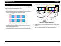
1.1.5 Ink Cartridges
1.1.6 Electrical Specifications
Shape:
Each ink cartridge is uniquely shaped so the
cartridges do not fit in the wrong slots.
Ink colors:
Black, Cyan, Magenta, Yellow, Light Cyan, Light
Magenta
Ink life:
Two years from production date
Ink volume:
110ml
Weight:
200g
Effective ink:
83.0g
Print capacity:
Table 1-10. Electrical Specifications
120V Model
220-240V Model
Rated voltage range
AC120V
AC220~240V
Input voltage range
AC90~132V
AC198~264V
Rated frequency range
50~60Hz
Input frequency range
49.5~60.5Hz
Rated current
A1 = approx. 28 pages at 720dpi and 40% coverage
A1 = approx. 11 pages at 720dpi and 100% coverage
D = approx. 26 pages at 720dpi and 40% coverage
A4 = approx. 3,800 pages at 360dpi and 5%
coverage
Dimensions:
25.1 x 141.1 x 105.3mm (WxDxH)
Weight:
Approx. 200g
Storage temperature:
See the table below
1.0A (Max. 1.6A)
0.5A (Max.0.8A)
Power consumption
standby mode = 15W or less
Energy Star Compliant
Insulation resistance
10MΩ minimum (between AC line and chassis, DC 500 V)
Dielectric strength
AC 1,000V rms per minute
or AC 1,200V rms per
second (between AC line
and chassis)
AC 1,500V rms per minute
(between AC line and
chassis)
.
Table 1-9. Ink Cartridge Specifications
Situation
Temperature
Notes
Transporting
-30~50°C
(-22~122°F)
• Less than a month at 40°C (104°F)
• Less than 120 hours at 50°C (122°F)
Storage
-20~40°C
(-7.6~104°F)
Less than a month at 40°C (104°F)
Installed
-30~40°C
(-22~104°F)
Less than a month at 40°C (104°F)
Do not refill or reuse cartridges; they are consumable items.
Do not use ink that beyond its expiration date. See above.
To use ink that has been frozen below -15 °C (5 °F), let it
thaw at least 3 hours at room temperature.
Product Description
Features
18
EPSON Stylus Pro 7000
1.1.7 Reliability
Revision B
1.1.8 Environmental Conditions
Total print volume:
20,000 pages at A1 size
Printheads:
2,000,000,000 dots/nozzle
Cutter:
Approximately 2,000 sheets (A1)
Maintenance parts:
Approximately 12,000 sheets
Ink pad, Pump unit, Flushing box, Cap assembly,
and Head Cleaner are all included in the SP-7000
Maintenance Kit (P/N 1054038)
TEMPERATURE/HUMIDITY
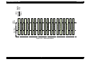
See the following table.
Table 1-11. Environmental Conditions
Condition
Temperature
Humidity
Operating
10~35°C
(50~95°F)
20~80%
Storage
-20~40°C
(-4~104°F)
20~85%
Transportation
-20~60°C
(-4~140°F)
5-85%
Notes
• Less than a month at
40°C (104°F)
• Less than 120 hours at
60°C (140°F)
• With no freezing
Notes:
1) When storing the printer, make sure the printheads are in the home (capped)
position. If necessary switch power on, wait for the printheads to move to the
home position, and then switch power off.
2) Before transporting the printer, remove the ink cartridges and turn the ink
valves screws to the closed position. Also make sure the printheads are in the
home, capped, position. After transporting the printer, install new ink
cartridges.
3) If the temperature drops below -15°C (5°F), the ink in the cartridges and
printheads freezes. The ink thaws completely after three hours at 25°C (77°F).
90
Humidity (%)
80
70
60
50
40
30
20
10
10
15
20
27 30
35
40
Temperature (°C)
Figure 1-2. Print Temperature and Humidity
Product Description
Features
19
EPSON Stylus Pro 7000
Revision B
1.1.9 Controller
VIBRATION & SHOCK
See the following table.
Table 1-12. Vibration and Shock
Condition
Vibration
Resistance
Shock
Resistance
Operating
0.15G
10~55Hz
1G
maximum 1ms
Storage
0.5G
10~55Hz
2G
maximum 2ms
CPU:
Hitachi SH7043, 33Mhz
RAM:
8MB + 2MB (fixed)
Interfaces:
IEEE1284
USB
Type B (one expansion port)
Notes
X/Y/Z directions
Notes:
* Make sure the printhead is capped during transportation and storage. To cap
the printhead, turn the power on (with ink cartridges installed) and turn the
power off when the printheads are capped.
* To thaw frozen ink in the printer or cartridge, leave the printer out at a
temperature of 25°C (77°F) for approximately three hours.
Product Description
Features
20
EPSON Stylus Pro 7000
Revision B
1.1.10 Conformity/Safety Approvals
1.1.11 Acoustic Noise
120V Model
Approx. 50dB(A) (According to ISO 7779)
Safety Standards:
UL1950
CSA 22.2 No. 950
EMI:
FCC part 15 subpart B class B
CSA C108.8 class B
220~240V Model
Safety Standards:
EN 60950
EMI:
EN55022 (CISPR Pub. 22) class B
AS/NZS 3548 class B
Product Description
Features
21
EPSON Stylus Pro 7000
Revision B
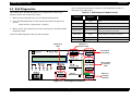
1.2 Interfaces
1.1.12 CE Marking
220~240V Model
Low Voltage Directive 73/23/EEC:
EN60950
EMC Directive 89/336/EEC
EN55022 Class B
EN61000-3-2
EN61000-3-3
EN50082-1
IEC801-2
IEC801-3
IEC801-4
Product Description
The EPSON Stylus Pro 7000 is equipped with parallel and USB interfaces as
well as an expansion slot for an optional Type-B interface. This section
provides information on each of these interfaces.
Interfaces
22
EPSON Stylus Pro 7000
Revision B
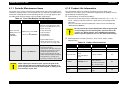
1.2.1 Parallel Interface - Compatibility Mode
The ERROR signal is low when there is a:
Printer hardware error (fatal error)
Table 1-13. Parallel Interface Specifications
Item
Paper-out error
Description
Paper-jam error
Transmission mode
8-bit parallel, IEEE-1284 compatibility mode
Synchronization
By STROBE pulse
Handshaking
By BUSY and ACKNLG signal
Logic Level
TTL compatible level (IEEE-1284 Level 1 device)
Connector
57-30360 (Amphenol) or equivalent
Ink-out error
NOTE: The PE signal is high during paper-out errors.
DATA TRANSMISSION TIMING
Note: Use a twisted-pair cable that is as short as possible.
DATA
The BUSY signal is set high before setting the -ERROR signal low or the PE
signal high. The BUSY signal remains high until all these signals return to
their normal, inactive state.
The BUSY signal is high:
data byte n + 1
thold
-STROBE
tsetup
tnext
tstb
BUSY
When receiving data
tready
When the input data buffer is full
tbusy
-ACKNLG
When the -INIT signal is low, or during hardware initialization
treply
During a printer error
When the parallel interface is not selected
Product Description
data byte n
tack
tnbusy
Figure 1-3. Data Transmission Timing
Interfaces
23
EPSON Stylus Pro 7000
Revision B
Table 1-14. Data transmission times
Parameter
Minimum
Maximum
tsetup
500 ns
-
thold
500 ns
-
tstb
500 ns
-
tready
0
-
tbusy
-
500 ns
tt-out*
-
120 ns
tt-in**
-
200 ns
treply
0
-
tack
Typical 2 us
tnbusy
0
-
tnext
0
-
* Rise and fall time of every output signal
** Rise and fall time of every input signal
Table 1-15. Typical tack time
Parallel I/F mode
Time required
High speed (default)
0.5us
Normal speed
2us
Product Description
Interfaces
24
EPSON Stylus Pro 7000
Revision B
Table 1-16. Connector Pin Assignments and signals - Forward
Channel
Pin
No.
Pin
No.
Signal
Name
Return
Pin
In/
Out
Functional Description
1
-STROBE
19
I
Data reception pulse. Data is read at the falling
edge of this pules.
2-9
DATA0~7
20-27
I
The DATA0 through DATA7 signals represent
data bits 0 to7, respectively. Each signal is at
high level when data is logical 1 and low level
when data is logical 0.
10
-ACKNLG
28
O
This signal is a negative pulse indicating that
the printer can again accept data.
11
BUSY
29
O
HIGH means the printer cannot receive data.
This occurs when the printer is receiving data
or when the printer is in an error state.
12
PE
28
O
HIGH means no paper is loaded.
13
SLCT
28
O
Always HIGH when the printer is on.
14
-AFXT
30
I
Not used
15
NC
-
-
Not connected
16
GND
Ground for twisted pair return
17
Chassis
GND
Ground for frame/body
18
Logic H
Pulled up to +5V via 3.9Kohm
19-30 GND
Table 1-16. Connector Pin Assignments and signals - Forward
Channel (continued)
Signal
Name
Return
Pin
In/
Out
Functional Description
34
NC
----
----
Not connected
35
+5V
----
O
HIGH during normal operation. Pulled up to
+5V via 1.0Kohm
36
-SLIN
30
I
Not used
Note: In (I) and Out (O) refer to the direction of signal flow from the printer’s point
of view.
Ground for twisted pair return
31
-INIT
30
I
Pulse width of 50uS or more means LOW
pulse, and the falling edge of LOW signal
causes the printer to initialize.
32
-ERROR
29
O
LOW means printer error
33
GND
----
----
Ground for twisted pair return
Product Description
Interfaces
25
EPSON Stylus Pro 7000
Revision B
1.2.2 Parallel Interface - Nibble Mode
Table 1-18. Connector Pin Assignments - Reverse Channel
Pin
No.
Table 1-17. Transmission Specifications
Description
1
Signal Name
HostClk
Return In/
Pin
Out
I
Host clock signal.
20-27
I
The DATA0 through DATA7 signals
represent data bits 0 to7, respectively.
Each signal is at high level when data is
logical 1 and low level when data is logical
0.
19
Transmission mode IEEE-1284 nibble mode
Synchronization
Refer to IEEE-1284 specification
Handshaking
Refer to IEEE-1284 specification
Signal level
TTL compatible (IEEE-1284 level 1 device)
Adaptable
connector
Data trans. timing
2-9
Data0-7
57-30360 (Amphenol) or equivalent
10
PtrClk
28
O
Printer clock signal
Refer to IEEE-1284 specification
11
PtrBusy/
DataBit-3,7
29
O
Printer busy signal and reverse channel
transfer data bit 3 or 7.
12
AckDataReq/
DataBit-2,6
28
O
Acknowledge data request signal and
reverse channel transfer data bit 2 or 6.
13
Xflag/
DataBit-1,5
28
O
X-flag signal and reverse channel transfer
data bit 1 or 5.
14
HostBusy
30
I
Host busy signal.
15
NC
Not connected
16
GND
Signal ground
17
Chassis GND
Chassis ground
18
Logic-H
The printer responds affirmatively when the extensibility
request values are 00H or 04H:
00H: Request Nibble Mode Reverse Channel Transfer
Extensibility request
04H: Request Device ID;
Return Data Using Nibble Mode Reverse Channel
Transfer
Device ID
Functional Description
The printer returns the following strings when the device ID
is requested:
<00H><4EH>
MFG: EPSON
CMD: ESCPL2, BDC
MDL: Stylus[SP]Pro[SP]7000
CLS: PRINTER
DES: EPSON[SP]Stylus[SP]Pro{SP]7000
Note: [00H] denotes a hexadecimal value of zero
MDL values depend on the EEPROM setting
O
Pulled up to +5V via 3.9K ohm resister.
19-30
GND
Ground for twisted pair return
31
-INIT
30
I
Not used.
32
-DataAvail/
DataBit-0,4
29
O
Data available signal and reverse channel
transfer data bit 0 or 4.
33
GND
Signal ground
34
NC
Not connected
35
+5V
----
O
Pulled up to +5V via 1.0K ohm resister.
36
1284-Active
30
I
1284 Active Signal
Note: In (I) and Out (O) refer to the direction of signal flow from the printer’s point
of view.
Product Description
Interfaces
26
EPSON Stylus Pro 7000
Revision B
1.2.3 Parallel interface - ECP mode
Table 1-19. Transmission Specifications
Description
Transmission mode IEEE-1284 ECP mode
Synchronization
Refer to IEEE-1284 specification
Handshaking
Refer to IEEE-1284 specification
Signal level
IEEE-1284 level 1 device
Adaptable
connector
See forward channel
Data trans. timing
Refer to IEEE-1284 specification
The printer responds affirmatively when the extensibility
request values are 10H or 14H:
10H: Request ECP Mode Reverse Channel Transfer
Extensibility request
14H: Request Device ID;
Return Data Using ECP Mode Reverse Channel
Transfer
Device ID
The printer returns the following strings when the device ID
is requested:
<00H><4EH>
MFG: EPSON
CMD: ESCPL2, BDC
MDL: Stylus[SP]Pro[SP]7000
CLS: PRINTER
DES: EPSON[SP]Stylus[SP]Pro{SP]7000
Note: [00H] denotes a hexadecimal value of zero
MDL values depend on the EEPROM setting
Product Description
Interfaces
27
EPSON Stylus Pro 7000
Revision B
Table 1-20. Connector Pin Assignments - ECP Mode
Table 1-20. Connector Pin Assignments - ECP Mode
Pin
No.
1
2-9
10
11
Signal Name
Return In/
Pin
Out
HostClk
Data0-7
19
20-27
PeriphClk
PeriphAck
28
29
Functional Description
nReverseReq
uest
30
I
This signal goes low to change to the
reverse channel.
32
nPeriphRequ
est
29
O
This signal produces a host interrupt.
33
GND
Ground for twisted pair return
I
The DATA0 through DATA7 signals
represent data bits 0 to7, respectively.
Each signal is at high level when data is
logical 1 and low level when data is logical
0. These signals are used to transfer the
1284 extensibility request values to the
printer.
34
NC
Not connected
35
+5V
----
O
Always HIGH. Pulled up to +5V via 1.0K
ohm resister.
36
1284-Active
30
I
1284 Active Signal. HIGH in ECP mode
O
Data is transferred from the printer to the
host.
O
The printer uses this signal for flow
control in the forward direction. Also used
for data bit 9 which indicates command
information and data to be output on the
data signal in the forward direction.
28
O
13
Xflag
28
O
X-flag signal and reverse channel transfer
data bit 1 or 5.
I
The host uses this signal for flow control
in the reverse direction. Also used for data
bit 9 which indicates command
information and data to be output on the
data signal in the forward directions.
14
HostAck
15
NC
Not connected
16
GND
Signal ground
17
Chassis GND
Chassis ground
18
PeriphLogicH
Product Description
Functional Description
31
nAckReverse
GND
Return In/
Pin
Out
Data or address information is transferred
from the host to the printer.
12
19-30
Signal Name
I
The printer goes to Low and approves the
nReverseRequest.Acknowledge data
request signal and reverse channel
transfer data bit 2 or 6.
30
Pin
No.
O
Note: In (I) and Out (O) refer to the direction of signal flow from the printer’s point
of view.
Always HIGH. Pulled up to +5V via 3.9K
ohm resister.
Ground for twisted pair return
Interfaces
28
EPSON Stylus Pro 7000
Revision B
1.2.4 USB
Device ID
Standard
:“Universal Serial Bus Specifications Revision 1.0”
“Universal Serial Bus Device Class Definition for
Printing Devices Version 1.0”
Bit rate
:12Mbps (Full speed device)
Data encoding
:NRZI
Adaptable connector
:USB series B
<00H><4EH>
MFG: EPSON
CMD: ESCPL2, BDC
MDL: Stylus[SP]Pro[SP]7000
CLS: PRINTER
DES: EPSON[SP]Stylus[SP]Pro{SP]7000
NOTE: To use USB interface: set “PARA.I/F=COMPAT.” in the Printer
Settings Menu.
Suggested cable length :2 meters
Table 1-21. USB connector pin assignments and signals
Pin no.
Signal name
In/Out
Description
1
VCC
-
Cable power, max. power consumption is
100mA
2
-Data
bi-directional data
3
+Data
bi-directional data, pull up to +3.3V via 1.5K Ω resistor
4
Ground
-
Pin #2
Pin #3
Cable ground
Pin #1
Pin #4
Figure 1-4. USB Pins
Product Description
Interfaces
29
EPSON Stylus Pro 7000
Revision B
1.2.5 TYPE-B Optional Interface
1.2.6 Preventing Data Transfer Time-Outs
The EPSON Stylus Pro 7000 supports a Type-B interface (level 2).
Generally, hosts abandon data transfer to peripherals when a peripheral is in
the busy state for dozens of seconds continuously. To prevent hosts from
entering this kind of time-out period, the printer slows down the data
reception rate to about one byte per second when there is less than 4kb of
free space in the printer buffer. Data reception comes to a complete stop if the
free space is less than 32 bytes, but returns to one byte per second when free
space reaches 1KB or more.
Reply message (short version):
When using a Co-ax/Twin-ax interface card:
Main type:
MTP48p, PW127cl10cpi, PRG (B0xxxx)rev,
AP1200ma
Product name: Stylus[SP]Pro[SP]7000
Emulation type: ESCPL2-00
Entity type:
EPSONLQ2
When using a card other than a Co-ax/Twin-ax interface card:
Main type:
MTP48p, PW127cl10cpi, PRG (B0xxx)rev,
AP1200ma, SPD0fast
Product name: Stylus[SP]Pro[SP]7000
Emulation type:ESCPL2-00
Entity type:
ESPONLQ2
Product Description
Interfaces
30
EPSON Stylus Pro 7000
Revision B
Interface status and selection
1.2.7 Interface Selection
The SP 7000 has one slot for an optional Type-B interface and two built-in
interfaces; the USB and parallel interfaces.
The printer has only two internal BUS lines for the interfaces, so the parallel
and USB interfaces share one line while the other line is exclusive to the
Type-B interface. The USB interface takes priority when both interfaces are
connected meaning the USB interface works but the parallel does not. Make
sure nothing is connected to the USB interface before printing via the parallel
interface.
The parallel or USB interface can operate normally even if an optional Type-B
interface is installed and connected. The interface in use can be selected
automatically or manually.
Manual selection
The interface can be manually determined using the Printer Setting
Menu; see SelecType in the user’s guide for details.
When the option interface is selected, the parallel/USB interface goes into
the busy state. The LH signal is “L” at this time. “L” means the power is
cut, in other words 1284 does not respond. Therefore, the LH check is
required via the Reverse channel. The USB interface responds NACK and
cannot receive data.
The the option interface is not selected, an off-line bit is set to Main Status
Register (MNSTS). When the printer initializes or returns to the idle state,
the USB interface is out of the NACK condition and resets the off-line bit
of the Main Status Register to option interface.
Be aware that an interrupt signal such as the -INIT signal only takes effect
on the parallel interface when the parallel interface is selected.
When the printer is initialized or returns to an idle state, the parallel
interface enters a ready condition, the serial DTR signal is set to low, and
the off-line bit of the Main Status Register (MNSTS) is reset.
The /INIT signal on the parallel interface is not active while that interface
is in Nibble or ECP Mode, or is not selected.
The choices are INTERFACE = PARA/USB or INTERFACE = OPTION.
Automatic selection
If the interface setting is set to “AUTO” (default), the printer scans the
interfaces for incoming data. The interface that receives data first is
selected.
As long as the host sends data or the printer interface is in the busy state,
the interface selection does not change.
When the host stops transferring data and the printer is in the stand-by
state for a certain period of time, the printer returns to the idle state.
Product Description
Interfaces
31
EPSON Stylus Pro 7000
Revision B
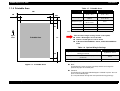
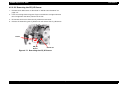
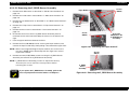
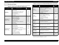
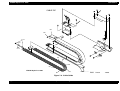
1.3 PHYSICAL SPECIFICATIONS
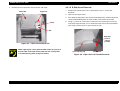
SETUP GUIDELINES
PRINTER DIMENSIONS & WEIGHT
When setting up the printer on a desk or table top, refer to the instruction and
illustration below. (When setting up the printer using the optional stand, see
the setup guide that comes with the stand for details.)
Dimensions:
1100 x 572 x 560mm (WxDxH)
(43.8 x 22.8 x 22.3 inches)
Weight:
43.5Kg (95.7 lb.s)
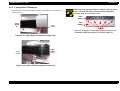
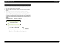
1.
Make sure the printer is 60~80cm (24~32”) off the floor.
2.
Make sure the nearest obstruction in front of the printer is at least 60cm
(24”) away.
Nearest
obstruction
Paper eject
direction
At least 60cm
60~80cm
Figure 1-5. Printer Dimensions
Floor
Product Description
Physical Specifications
32
EPSON Stylus Pro 7000
Revision B
CUTTER SPECIFICATIONS
Attributes:
Consumable item that is replaced by the user, and it
is made of very hard steel, so the blade can be
chipped. Handle carefully to avoid cuts to yourself
and to avoid chipping the blade.
Life:
The cutter can cut well over 2,000 sheets of paper,
but the actual wear-and-tear depends on the type
and thickness of the paper used.
The cutter life can be determined manually; attempt
to cut a piece of normal paper and if the cutter easily
cuts the paper, it is OK.
Unlike the cutter position with the EPSON Stylus Pro
9000, the SP 7000 cutter position is automatically
determined by the carriage cover position. No
adjustment is needed for the cutter position or the
carriage cover height.
Product Description
Physical Specifications
33
EPSON Stylus Pro 7000
Revision B
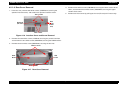
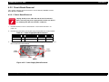
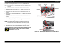
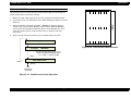
1.4 Control Panel
Table 1-22. Buttons and Functions
This section describes the control panel, the buttons, the lights, and the way
you make settings.
Button
(Second function)
Function
(Normal)
SelecType
Function
Power-On
Function
Power
Power on/off
N/A
N/A
Pause
(Reset)
• Switch -pause/ready
• Reset (press 3 seconds)
N/A
Maintenance
Mode
SelecType
• Enters SelecType mode
• Opens Cutter
Replacement Menu
(press for five seconds)
Selects menu or
major category
Cut/Eject
(Enter)
Figure 1-6. Control Panel
BUTTONS
All eight buttons on the control panel and their functions are described below.
Selects *1
• Auto Cut
• Cutter Off
• Sheet
Confirms and saves
setup values
Paper Feed ↑
Feeds paper backward *2
Cycles backward/
increases value
Paper Feed ↓
Feeds paper forward *3
Cycles forward/
decrease value
Paper Source
(Item)
Selects paper source
Selects item or
minor category
Cleaning
Cleans both heads (press
for three seconds)
N/A
Paper Source +
Cut/Eject +
Paper Feed ↓
Paper Source +
Cut/Eject +
Cleaning
N/A
Maintenance
Mode 2
N/A
Firmware
Update
Mode
Notes:
1: Interrupts ink drying and runs the specified operation.
2: 1.27cm/second paper feed for 2 seconds after key is pressed. 7.62cm/second
paper feed if pressed for over two seconds. Maximum feed of 20cm with one
press of the button.
3: 1.27cm/second paper feed for 2 seconds after key is pressed. 7.62cm/second
paper feed if pressed for over two seconds.
Product Description
Control Panel
34
EPSON Stylus Pro 7000
Revision B
LED INDICATORS
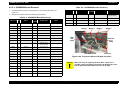
Table 1-23. LED Indicator Lights
LED
Operate
Status
• On
• Flashing
• On
• Flashing
Paper Out
Pause
Ink Out Y
Ink Out LM
Ink Out LC
Ink Out M
Ink Out C
Ink Out K
Roll Auto Cut
Paper Type
(Cut Off)
Sheet
• On
• Flashing
•
•
•
•
•
•
•
•
•
•
•
•
•
•
On
Flashing
On
Flashing
On
Flashing
On
Flashing
On
Flashing
On
Flashing
On
Flashing
• On
• Flashing
• On
• Flashing
Condition
• Power on
• Receiving data or performing power-down
sequence
• No paper loaded, end of roll, sheet/roll paper
error, paper set lever is in release position, or
the loaded paper is too thick for cleaning
• Paper jam, paper cutting, paper skew, or paper
check error
• Paused
• Performing head cleaning or the printer is in
ink drying phase. Also flashes during ink
charging operation.
• Ink out*
• Ink low
• Ink out*
• Ink low
• Ink out*
• Ink low
• Ink out*
• Ink low
• Ink out*
• Ink low
• Ink out*
• Ink low
• Auto cut selected
• Roll paper not set or roll paper and cut sheet
sizes are different
• Roll paper will not be cut
• Roll paper not set or roll paper and cut sheet
sizes are different
• Single sheet printing mode.
• Roll paper not set or roll paper and cut sheet
sizes are different
Note: *Also occurs if no cartridge is installed or the wrong cartridge is installed.
Product Description
Control Panel
35
EPSON Stylus Pro 7000
Revision B
1.4.1 Indicator Status in Normal Mode
Table 1-26. Pause Indicator
Table 1-24. Operate Indicator
Printer Status
Indicator
With power on and in any status other
than those listed below.
On
While processing data and during power
off sequence
Flashing
Fatal error
Flashing
Reset, timer IC reset/NVRAM clear
On
Table 1-25. Paper Out Indicator
Printer Status
Indicator
Out of paper, end of roll
On
Roll paper and sheet sizes are different
On
Paper set lever in release position
On
Paper is too thick to perform cleaning
Printer Status
Indicator
Ready
Off
In SelecType mode
Off
Paused
Off
Ink drying phase
Flashing
Ink charging sequence
Flashing
Other errors
Off
Fatal error
Flashing
Reset, timer IC reset/NVRAM clear
On
Table 1-27. Ink Out Indicators
Printer Status
Indicator
On
On
Out of specified ink
No I/C for specified ink
Wrong I/C for that slot
Paper jam
Flashing
Ink low
Flashing
Paper cutting error
Flashing
Fatal error
Flashing
Paper skew
Flashing
Reset, timer IC reset/NVRAM clear
On
Paper check error
Flashing
Problem with paper eject (sheet)
Flashing
Fatal error
Flashing
Reset, timer IC reset/NVRAM clear
On
Product Description
Control Panel
36
EPSON Stylus Pro 7000
Revision B
1.4.2 Control Panel Messages
Table 1-29. Control Panel Messages (continued)
Display Message
Table 1-28. Paper Source Indicator
Printer Status
Indicator
Selected paper source
On
Fatal error
Flashing
Roll paper and sheet sizes are different
Flashing
Reset, timer IC reset/NVRAM clear
On
READY *
WAIT *
Printer status and error messages appear on the control panel display. The
table below lists the messages.
INK CHARGING nnn%
Table 1-29. Control Panel Messages
Display Message
INK DRY xx MIN *
Meaning
SERVICE REQ. nnnnnnnn
Fatal error - see “Service Requests” on
page 48
PRESS PAUSE BUTTON
TURN PWR OFF AND ON
Turn the printer off and on to reinitialize
LOAD xxx PAPER
RESET
TRANSPORT PREP nn%
POWER OFF
COVER OPEN
SECURE PAPER LEVER
In the process of re-initializing.
See “Transportation Mode” on page 53
Paper Set lever is in the released and cannot
continue or begin a print, cleaning, or
initialization sequence.
NO INK CARTRIDGE
One or more cartridges are not installed
OPTION I/F ERROR
An unsupported Type-B interface card is
installed.
INK OUT
Product Description
Control Panel
Resetting Timer IC
Clearing NVRAM
Performing reset operation
Performing ink sequence operation
Initializing the printer
Initializing the paper
Initial charging of ink - shown in percent
completed
Printer waits xx minutes before the next print
job to allow enough time for ink to dry on
previous print job.
Waiting for paper initialize start trigger
Wrong paper loaded or wrong paper source
selected on control panel.
The Paper Set Lever is in the released position
(before printing). Pull the Paper Set lever
forward to the set position
PAPER JAM
Both front and rear paper sensors detect paper
and there is a carriage over-current or out of
step error. This is due to:
• Paper is jammed inside the printer
• Paper is obstructing the carriage path
during feeding or cutting operation.
PAPER NOT CUT
Printer did not cut the paper completely, or the
cut piece still remains over the paper sensor
PAPER NOT STRAIGHT
• A predetermined amount of ink has been
consumed after the cartridge has entered
the near-end condition.
• A near-end cartridge has been removed and
re-installed.
Can receive and print data.
LOAD PAPER
Preparing to shut down.
The cover is open. The carriage stops in place,
and the printhead can be damaged if the head
remains out of the capped position for a long
period of time.
Meaning
Paper skewed more than 3mm between the
leading and following edges. Check the
printout for skew and make sure no ink was
fired onto the platen.
37
EPSON Stylus Pro 7000
Revision B
1.4.3 Panel Display Priority
Table 1-29. Control Panel Messages (continued)
Display Message
UNABLE TO PRINT
RELOAD PAPER
REMOVE PAPER
PAUSE
INK LOW
MAINTENANCE REQ. nnnn
Meaning
High priority to low priority
When trying to print a test or adjustment
pattern, one of the following occurs:
• Paper not loaded
• Ink cartridge not loaded
• Paper detection error
Fatal errors/restart required
Reset, timer IC rest/NVRAM clear
Entering or in power-off sequence/transport preparation sequence
• The paper was loaded too far forward and
cannot be backward fed to the proper
position.
• The paper’s horizontal position exceeds the
normal printable area when the paper is
loaded.
• The paper’s horizontal position exceeds the
normal cutting area after printing.
• The cut sheet is too long and cannot be
ejected properly.
• Recovery from cutter error.
Entering or in ink-cartridge-replacement sequence
Cover open
Paper set lever released during operation
Type B interface error
No ink cartridge
Wrong ink cartridge
Ink out
Roll paper and sheet sizes are different
Paper jam
Paper set lever in release position
Paper cutting error
Paper not straight
Paper check error
Roll paper end
Paper eject error
Loaded paper is too thick to perform timer
cleaning
Pause state.
When total dots fired = 90%, cartridge enters
near-end condition. Remaining ink = A1 at
100% duty
Initializing
Paper is too thick for cleaning
Entering or in ink sequence
Waiting for paper-initialization trigger
Paused
Entering or in paper initialization
Entering or in ink drying time-out
Ink low/Maintenance required
Printer requires maintenance - see
“Maintenance Request” on page 47
PRINTING *
Processing print data.
PAPER OUT
• No paper loaded
• End of roll paper (printer stops feeding)
• End of sheet paper (when paper feeds to
eject position, put hand under the sheet and
press Cut/Eject to release)
Processing data/printer ready
Out of paper
Notes*: If the printer’s platen gap setting is set to Thick, a “H” will appear in the
last space on the LCD display.
Product Description
Control Panel
38
EPSON Stylus Pro 7000
Revision B
To use cut sheets
1.5 Loading Paper
smaller than A3+ size cut sheets
To automatically cut off the printed roll paper after printing:
1.
Select Sheet using the Paper Source button.
2.
Make sure the paper set lever is in the forward (set) position, and load a
sheet in the paper insertion slot
3.
Load the paper from the paper insertion slot and align it with the paper
guideline.
Push the Paper Feed or Pause button (you need to press one) to feed the
paper forward to the standby position. The printer is ready to receive
print data.
4.
Pull the paper set lever forward to the set position.
A3+ or larger size cut sheets
5.
If the surface of the paper is dirty or indented anywhere, use the Paper
Feed buttons to skip over that area. When that area passes the cut off line,
press the Cut/Eject button. This trims the unusable section of paper, and
the printer is now ready to print.
1.
Push back the paper set lever to the release position. The printer is
incapable of printing.
2.
Select Sheet using the Paper Source button.
Push the Pause button or wait ten seconds to automatically feed the
paper back to the standby position. The printer is ready to receive print
data, print it, and cut off the paper.
3.
Load the paper from the paper insertion slot and align it with the paper
guideline.
4.
Pull the paper set lever forward to the set position.
5.
Push the Pause button or wait ten seconds to automatically feed the
paper forward to the standby position. The printer is ready to receive
print data.
1.
Push back the paper set lever to the release position. The printer is
incapable of printing.
2.
Select Roll, Auto Cut using the Paper Source button.
3.
6.
To print and not cut off the roll paper:
1.
Pull up the paper set lever to the release position. The printer is incapable
of printing.
2.
Select Roll, Cutter Off using the Paper Source button.
3.
Load the paper from the paper insertion slot and align it with the paper
guideline.
4.
Pull the paper set lever forward to the set position.
5.
If the surface of the paper is dirty or indented anywhere, use the Paper
Feed buttons to skip over that area. When that area passes the cut off line,
press the Cut/Eject button. This trims the unusable section of paper, and
the printer is now ready to print.
6.
Push the Pause button or wait ten seconds to automatically feed the
paper forward to the standby position. The printer is ready to receive
print data and print.
Product Description
Loading Paper
39
EPSON Stylus Pro 7000
Revision B
Exiting SelecType mode
1.6 SelecType Settings
Select one of the following methods to exit SelecType mode:
Entering SelecType mode
Press the Pause button while in SelecType mode; the printer is ready
To access the control panel settings, press the SelecType button while the
printer is not printing. The printer enters the SelecType mode and cannot
print.
Using SelecType mode
1.
TEST PRINT MENU
PRINTER STATUS MENU
PAPER CONFIG. MENU
Replace the cutter.
Press the SelecType button several times at the top level of
Press the SelecType button one time at the second level of SelecType
For details, see
“Printer Setting Menu” on page 41
menus.
“Test Print Menu” on page 42
“Printer Status Menu” on page 44
“Paper Configuration Settings” on page 44
CUTTER REPLACE MENU
“Cutter Replacement Menu” on page 45
HEAD ALIGNMENT MENU
“Head Alignment Menu” on page 46
2.
Press the Item button to select the choice shown in the LCD display.
3.
Press the SelecType button to view the options for that Item.
4.
Press the “+” button or “-” button to view the available values for an
option.
5.
Press the Enter button to record the current option or to execute the
operation shown in the display.
Product Description
Print a status sheet.
SelecType menus.
Table 1-30. SelecType Menus
PRINTER SETTING MENU
Perform the printer initialization.
Print a nozzle check pattern.
Repeatedly press the SelecType button to view the SelecType menus
which appear in the order shown below.
Display Message
to print.
SelecType Settings
40
EPSON Stylus Pro 7000
Revision B
Platen gap
1.6.1 Printer Setting Menu
You can adjust the platen gap using this option. (See “Platen Gap
Mechanism” on page 70 for details.)
Table 1-31. Printer Setting Menu
Display Message
Options
Notes
PLATEN GAP
Auto
Wide
Adjusts the platen gap. (Normally, leave
set to Auto.)
PAGE LINE
ON
OFF
When Auto Cut Off is selected on the
control panel, this setting determines
whether a line for manual cutting is
printed.
Auto
Para/USB
Option
Determines which interface the printer
checks for data. Auto continuously
checks all interfaces and is good for
normal use.
PARA. I/F
Compat
ECP
Determines the data transfer rate when
using this interface.(Normally, leave set
to Compatible.)
CODE PAGE
PC437
PC850
Character code setting. (PC437:
expanded graphics/PC850: multi-lingual)
INTERFACE
Roll paper margin
T/B 15MM = the printed image is the same size whether the margin is
15mm or 3mm. The difference is 12mm of paper clearance is added to the
top and bottom edges to make paper feeding more stable and to prevent
the paper from rubbing the printheads.
If the print area is greater than the width of the printable area of the
paper, the printer ignores the extra print data on the right side of the
paper.
Paper size check
You can disable the paper size check to prevent “RELOAD PAPER” errors
which may occur when using very thin paper or paper with low reflective
qualities such as tracing paper.
The print area is determined manually, and the printheads will fire ink
onto the platen if the print area is set larger than the actual paper size.
Roll sheet margin setting.
• Top/Bottom 15mm*
top and bottom margins = 15mm
left and right margins = 3mm
• 15mm: all margins = 15mm
• 3mm all margins = 3mm
ROLL MARG
T/B 15MM
15MM
3MM
PAPER SIZE CHK
ON
OFF
Determines whether the paper size check
is enabled
PAPER ALIGN CHK
ON
OFF
Determines whether the paper skew
check is enabled
INIT. PANEL
Exec.
Initializes control panel setup values to
their defaults
Notes:
* The printed image is the same size whether the margin is 15mm or 3mm. The
difference is 12mm of paper clearance is added to the top and bottom edges to
make paper feeding more stable and to prevent the paper from rubbing the
printheads.
The underlined item equals the default.
Product Description
SelecType Settings
41
EPSON Stylus Pro 7000
Revision B
1.6.2 Test Print Menu
1.6.2.2 Status sheet
Table 1-32. Test Print Menu
Display Message
Item
Notes
NOZZLE CHECK
Print
Check the printout, any missing lines
mean the nozzle(s) are clogged.
STATUS SHEET
Print
Prints the current printer settings.
1.6.2.1 Nozzle check
Version: BO289C
Ink Pad: 94%
Note: the actual pattern prints in color: black, cyan,
magenta, light cyan, light magenta, and yellow
The firmware version is described as the date the firmware was set.
BO = EPSON Stylus Pro 7000
28 = date
9 = last digit of year (1999 in this case)
C = month (16H, so 1 means January, A means October and C means
December)
The remaining capacity of the waste ink pads is shown as a percentage.
Head Gap = see Platen Gap in Printer Status Menu, page 44
Border Line = see Page Line in Printer Status Menu, page 44
Interface = See Table 1-31, “Printer Setting Menu,” on page 41
Parallel I/F = See Table 1-31, “Printer Setting Menu,” on page 41
Product Description
SelecType Settings
42
EPSON Stylus Pro 7000
Revision B
Ink Pad = waste ink count, see below
Code page = PC 437 (US/Europe) or PC 850
Version = Firmware version
E***** F
100~81% remaining
Ink Left = see below
E**** F
80~61% remaining
E***** F
100~81% remaining
E***
F
60~41% remaining
E**** F
80~61% remaining
E**
F
40~21% remaining
E***
F
60~41% remaining
E*
F
20~1% remaining
E**
F
40~20% remaining
E
F
Less than 1% remaining (Maintenance Req 0100)
E*
F
20%~near end
when the ink pads are calculated to be full, Service Req. 00000100 occurs
and the printer cannot print.
nn%
near end ~ ink end (Ink End LED = flashing)
0%
ink end (Ink End LED = on)
After replacing the waste ink pads, clear the waste ink counter with
Maintenance Mode 2. See page 50.
Cutter Life
CR Motor life = Monitors carriage passes to notify when ink tubes
need replacing. See above for count explanation. Service Req.
00000101 occurs when the count equals 0.
The values are approximate and will vary depending on usage.
Table 1-33. Cutter Life Value
Printed Value
Meaning
E*****F
100-81% remaining
E**** F
80~61% remaining
E*** F
60~41% remaining
E** F
40~20% remaining
E*
F
20~1% remaining
E
F
less than 1% remaining
PF Motor life = Monitors the feed drive mechanism. See above for
count explanation. No fatal error.
Head = Keeps track of the number of dots fired from the head
according to color. The color that has been fired most is shown on the
Status Sheet. See above for count explanation. No fatal error. Part
replacement is determined on site.
Cleaner = Keeps track of the number of head cleaning operations
(wiping/rubbing). See above for count explanation. No fatal error. Part
replacement is determined on site.
When the cutter life = less than 1%, the cutter should be checked (it is OK if it
cuts a clean, straight line) and replaced if necessary. This is a subjective check
and the cutter does not have to be replaced if it still cuts properly.
Users can replace the cutter themselves.
Page count = total number of printed pages (max. six digits)
Product Description
SelecType Settings
43
EPSON Stylus Pro 7000
Revision B
1.6.3 Printer Status Menu
1.6.4 Paper Configuration Settings
All consumable items and maintenance parts either run out of their contents
or wear out. To determine how much contents (ink) or useful life remains,
compare the message and value shown on the control panel display to the
corresponding value below and the messages in the table below.
E*****
E****
E***
E**
E*
E
F
F
F
F
F
F
Table 1-35. Paper Config. Menu
Display Message
Item
Notes
PAPER NUMBER
STD
1~4
Select Standard for EPSON special paper.
Select the appropriate number for thick
paper.
THICK. PAT.*
Print
Prints a pattern to detect the paper
thickness. If “Paper Number” is set to
“Standard”, this message does not
appear.
PAPER THICK. NO.
1~17
Select the paper thickness number. If
“Paper Number” is set to “Standard”, this
message does not appear.
100~81% full/life remaining
80~61% full/life remaining
60~41% full/life remaining
40~21% full/life remaining
20~1% full/life remaining (generates a warning)
Less than 1% full/life remaining (generates an error)
Table 1-34. Printer Status Menu
Display message
VERSION
Meaning
Shows the firmware version.
DRYING TIME
INK LEFT-K
Shows the amount of remaining ink - Black
INK LEFT-C
Shows the amount of remaining ink - Cyan
INK LEFT-M
Shows the amount of remaining ink - Magenta
INK LEFT-LC
Shows the amount of remaining ink - Light Cyan
INK LEFT-LM
Shows the amount of remaining ink - Light
Magenta
INK LEFT-Y
Shows the amount of remaining ink - Yellow
CUTTER LIFE
Shows the remaining useful life of the cutter
SUCTION
Determines the length of time the printer
allows the ink to dry. When printing on
0 MIN ~30 MIN
roll paper, the printer will wait the
specified time after printing
NORM
LOW
The vacuum setting.
Note: The underlined item equals the default.
* The paper thickness detection function is enabled only when PAPER
NUMBER equals something other than standard.
1.6.4.1 Detecting Paper Thickness
WASTE INK
Maintenance information
This option allows the user to detect the thickness of available paper, and
register up to four user-defined paper types. Ink drying time can also be
registered.
CR MOTOR
Maintenance information
1.
Load a sheet of A4 or larger size paper.
PF MOTOR
Maintenance information
2.
Press the SelecType button to enter SelecType mode.
HEAD UNIT
Maintenance information
3.
Select the Paper Config. menu, and press the Item button.
CLEANER
Maintenance information
4.
Select a paper number, one to four. (If you use EPSON media, select STD
and proceed to step 4.)
TOTAL PRINTS
Product Description
Shows the total number of printed documents
SelecType Settings
44
EPSON Stylus Pro 7000
5.
Revision B
Press Item and confirm that “THICK. PAT. = Print” appears on the display.
Then press Enter to print the paper thickness pattern.
1.6.5 Cutter Replacement Menu
Print the Status Sheet from the Test Print menu in SelecType mode and see
page 43 for information on determining when the cutter needs to be replaced.
The following table includes the steps/messages that must be followed to
replace the cutter.
Table 1-36. Cutter Replace Menu
Display Message
Notes
CUTTER REPLACE MENU Prepare a replacement cutter and
OPEN LOWER COVER
Open the front cover.
REPLACE CUTTER
Push down on the cutter itself and
move the cap (actuator) to the right.
Remove the old cutter and install a
new one. Make sure the cap is
correctly replaced over the cutter.
CLOSE LOWER COVER
Close the front cover. The printer is
ready and the cutter counter is
automatically reset.
A4 printable
area
If you need to replace the cutter:
Select the number of
the set of lines that is
vertically aligned.
The numbers above represent
0.1mm increments between the
head and platen, with “1” being
0.0mm and “17” being 1.6mm.
1.
Press the SelecType button until CUTTER REPLACE MENU appears on the
LCD. (You can automatically enter the cutter replacement menu by
pressing the SelecType button for five seconds.)
2.
Open the Lower Cover (as shown on the LCD).
3.
While pushing down the cutter (the lower of the two extensions on the
left), slide the cutter actuator extension up and to the right.
4.
Remove the old cutter and replace with a new one.
5.
Close the Lower Cover (as shown on the LCD).
Figure 1-7. Paper Thickness Pattern
6.
Select the number of the most vertically aligned pair of lines, and press
Enter. (#5 is correct in the example below).
If necessary, select Drying Time from the Paper Config menu to select an
automatic period of time that the printer will pause printing to let the
previously printed sheet dry. Also, to prevent thin or light paper from getting
stuck over the paper suction holes in the Lower Paper Guide, you can select
Low (50% power) as the Suction setting.
Product Description
SelecType Settings
45
EPSON Stylus Pro 7000
Revision B
1.6.6 Head Alignment Menu
The head alignment function allows you to perform the parallelism
adjustment. See the illustrations and table below for details.
To perform the parallelism adjustment:
1.
Load A1-size roll paper.
2.
Press the SelecType button and select the Head Alignment Menu. Then
press the Item button.
3.
If using EPSON special media (paper thickness = 0.2~1.2mm), select
“STD”. If using other media, enter the paper thickness in 0.1mm
increments. (See “Detecting Paper Thickness” on page 44 if necessary.)
Press Enter.
4.
Select the pattern #1~12 or patterns “ALL” that you want to print. See the
table below for details. Press the Enter button to print the test patterns.
5.
There are twelve sections in the printout, and for each section determine
which pattern is vertically aligned and enter the corresponding value
(1~7). You will notice in the printout that sections six through eight are a
little different than the others.
Incorrect
Correct
Effective Buttons
Item = next
Enter = select
PF +/- = change
This is too far
apart. In this
example, #4 is
the correct
pattern.
Figure 1-9. Head alignment printout
Figure 1-8. Head Alignment sections
The adjustment values for head parallelism are stored in NVRAM.
Product Description
SelecType Settings
46
EPSON Stylus Pro 7000
Revision B
1.7 Maintenance Request
Table 1-37. Head Alignment Menu
Display Messages
Item
Notes
Select the thickness, to 0.1mm, of the
paper you are using to check the platen
gap. Normally, leave set to Standard.
There are several consumable parts in the printer, and the printer employs
separate counters to keep track of each one. The “Maintenance Req. 0100”
message appears on the display to warn the user when the Waste Ink pads
are about 99% full.
PAPER THICK
STD
0.0~1.6mm
ADJUST. PATT.
All
#1~12
Selects which patterns to print. (All
patterns or selected patterns only.)
#1
1~4~7
Bi-D adjust 1 (200cps, Normal Dot, left)
#2
1~4~7
Bi-D adjust 2 (200cps, Normal Dot, right)
The printer can continue to print even though the “Maintenance Req. 0100*
message appears instead of the “Ready” or “Printing” message. However,
when the waste ink counter determines the Waste Ink pads are 100% full, the
“Service Req 00000100” message appears and the printer can no longer print.
#3
1~4~7
Bi-D adjust 3 (200cps, Micro Dot, left)
To clear this condition, perform the following.
#4
1~4~7
Bi-D adjust 4 (200cps, Micro Dot, right)
#5
1~4~7
Bi-D adjust 5 (300cps, Normal Dot, left)
#6
1~4~7
Bi-D adjust 6 (300cps, Normal Dot, right)
#7
1~4~7
Bi-D adjust 7 (300cps, Micro Dot, left)
#8
1~4~7
Bi-D adjust 8 (300cps, Micro Dot, right)
#9
1~4~7
L/R adjust 1 (200cps, Normal Dot)
#10
1~4~7
L/R adjust 2 (200cps, Micro Dot)
#11
1~4~7
L/R adjust 3 (300cps, Normal Dot)
#12
1~4~7
L/R adjust 4 (300cps, Micro Dot)
Replace:
The following items must be replaced.
- Waste Ink Pads
- Pump Assembly
- Cap Assembly
- FBox
- Cleaner, Head
C H E C K
P O IN T
The above mentioned items are available as a kit.
Description: MAINTENANCE KIT
Parts code: 1054038
Note: The underlined item equals the default.
Required Adjustments:
Perform the following adjustments after replacing
the maintenance parts.
- Waste Ink Counter Clear
(See “Maintenance Mode 2” on page 50)
- Cleaner Counter
(See “Maintenance Mode 2” on page 50)
Product Description
Maintenance Request
47
EPSON Stylus Pro 7000
Revision B
1.8 Service Requests
Table 1-38. Service Errors (continued)
Service Code
When “Service Req nnnnnnnn” appears on the LCD display, a fatal error
requiring a service technician has occurred. The nnnnnnnn indicates what
needs to be fixed to return the printer to a working state.
Table 1-38. Service Errors
Service Code
Explanation
0000101
Ink tube life error
0001000
PF Motor encoder check error
0001001
PF Motor out of step
00010002
PF Motor overcurrent
00010003
PF Motor in-position time-out error
00010004
CR Motor encoder check error
00010005
CR Motor out of step
00010006
CR Motor overcurrent
00010007
CR Motor in-position time-out error
00010008
Servo interrupt watchdog time-out error
00010009
System interrupt watchdog time-out error
0001000A
CR origin sensor error
0001000B
PF origin sensor error
0001000C
PG origin sensor error (Head slide error)
0001000D
Cover sensor error (00)
0001000E
Cover sensor error (01)
0001000F
CR motor PWM output error
00010010
PF motor PWM output error
00020000
NVRAM Error
00020001
Internal RAM Check Error
00020002
SRAM Check Error
00020003
DRAM Check Error
Product Description
Explanation
0002000B
Mail box receiving error
100000004
CPU Vector 4 - General illegal instruction
100000006
CPU Vector 6 - Slot illegal instruction
100000006
CPU Vector 9 - CPU address error
10000000A
CPU Vector 10 - DMAC\DTC address error
10000000B
CPU Vector 11 - Watchdog time-out error
1000000**
CPU Vector 32~63; wrong trap
C A U T IO N
When replacing the following parts to clear “Service Req.
00000100” error, you need to clear the corresponding counter
using “Maintenance Mode 2”.
[Affected parts] (Maintenance Kit SP7000)
Waste Ink Pads
Flushing Box
Pump Assembly
Cap Assembly
Cleaner, Head
[Affected counters]
Init. Waste Ink
Init. Cleaning Unit
C H E C K
P O IN T
The above mentioned parts are also available as a KIT.
Description: MAINTENANCE KIT
Parts code: 1054038
Service Requests
48
EPSON Stylus Pro 7000
Revision B
1.8.1 Maintenance And Diagnostic Modes
MAINTENANCE MODE
When the printer is not functioning properly, there are three modes that help
you detect what is wrong and can help you fix the problem. These modes are
“Maintenance Mode”, “Maintenance Mode 2”, and “Self-Diagnostic Mode”.
To enter a mode, press and hold down the appropriate button (described
below) while turning on the printer.
To enter:
For details on how to make settings, see “SelecType Settings” on page 40. To
exit a mode, turn the printer off and on again.
C A U T IO N
Table 1-39. Maintenance Mode
Message
Hex Dump
The following explanations regarding control panel service
functions are for service and support purposes only; do not
share this information with the user.
Language
Product Description
While pressing the Pause button, turn the printer on.
Service Requests
Item
Explanation
Print
Prints the print data in hexadecimal
form, allowing you to confirm whether
the print data from the host PC is
properly sent/received. Press the Pause
key to stop printing and turn off the
printer to exit.
English, French,
Italian, German, Determines which language is used to
display messages on the LCD display.
Spanish,
Portuguese
49
EPSON Stylus Pro 7000
Revision B
Table 1-40. Maintenance Mode 2 - (NVRAM) counter value menu
MAINTENANCE MODE 2
To enter:
While Pressing the Paper Source + Cut/Eject + Paper
Feed ↓ buttons, turn the printer on.
Table 1-40. Maintenance Mode 2 - (NVRAM) counter value menu
LCD Message
INIT. ALL
Item
(decimal)
Description
Exec
Initializes NVRAM, Timer, life
counters, and mechanical
counters
LCD Message
Item
(decimal)
INK Y
0~4294967295
Ink remaining value (Y)
CUTTER
0~4294967295
Cutter life value
TTL PAGES
0~4294967295
Total printed pages value
WAST. INK A
0~4294967295
Waste ink A value
WAST INK B
0~4294967295
Waste ink B value
CR MOTOR
0~4294967295
CR motor life value
PF MOTOR
0~4294967295
PF motor life value
Description
INIT. NVRAM
Exec
Initializes NVRAM
INIT. TIMER
Exec
Initializes timer
HEAD K
0~4294967295
Head unit (K)
INIT. CR MTR
Exec
Initializes CR Motor counter
(after replacing ink tubes)
HEAD C
0~4294967295
Head unit (C)
HEAD M
0~4294967295
Head unit (M)
INIT. PF MTR
Exec
Initializes PF Motor counter
HEAD LC
0~4294967295
Head unit (LC)
Exec
Initializes Head unit counter
HEAD LM
0~4294967295
Head unit (LM)
INIT. CLEANER
Exec
Initializes cleaning unit
counter
HEAD Y
0~4294967295
Head unit (Y)
INIT. TTL PR
Exec
Initializes total print counter
CLEANER
0~4294967295
Cleaning unit life value
INIT. INK
Exec
Initializes ink counter
INIT. WA. INK
Exec
Initializes waste ink counter
BID OFFSET #1
-4~0~+4
Right head Bi-D offset setting
#1 (for Normal Dot 300cps)
BID OFFSET #2
-4~0~+4
Right head Bi-D offset setting
#2 (for Micro Dot 300cps)
CLR HEAD ERROR
Exec
INK K
0~4294967295
Ink remaining value (K)
INK C
0~4294967295
Ink remaining value (C)
INK M
0~4294967295
Ink remaining value (M)
INK LC
0~4294967295
Ink remaining value (LC)
INK LM
0~4294967295
Ink remaining value (LM)
INIT. HEAD
Product Description
Clear head error
Service Requests
50
EPSON Stylus Pro 7000
SELF-DIAGNOSTIC MODE
Power-on button:
Revision B
1.9 Firmware Update
Paper Feed ↓ + Cut/Eject + Cleaning
This mode is used primarily for replacing worn-out printer parts and
adjustment operations. For details, see Chapter 5, "Adjustment".
C H E C K
P O IN T
The information contained in this section is not to be shared
publicly.
The firmware contained on the Main Board is Flash ROM; therefore if you
need to update the firmware or replace the Main Board, see “Parameter
Backup” on page 159 and “Firmware Update” on page 162 for details.
Product Description
Firmware Update
51
EPSON Stylus Pro 7000
Revision B
1.10 Jumper Settings
1.11 Initialization
The factory default settings for jumper and DIP switch on the Main Board
(C299MAIN) are as follows.
There are three ways to initialize the EPSON Stylus Pro 7000:
Table 1-41. Jumper Settings
Hardware initialization:
When the power is turned on or a cold-reset command is sent to the
printer (remote RS command), the printer does the following:
Type
Number
Setting
Jumper
JP1
Jumpered
Initializes the printer mechanism
Jumper
JP2
Jumpered
Clears the input data buffer
DIP-SW
SWD1 “1” (1-4)
OFF (Open)
Clears the print buffer
DIP-SW
SWD1 “2” (2-3)
OFF (Open)
Restores the default values
Software initialization:
When the printer receives an ESC @ command, it does the following:
Clears the print buffer
Restores the default values
Control panel (operator) initialization:
When the Pause button is pressed for more than two seconds or the
printer receives an -INIT signal (negative pulse) from the parallel
interface, the printer:
If a single sheet is loaded, the printer ejects the sheet. If roll paper is
loaded and Auto Cut is selected, the printer cuts the printed area off
and reverse feeds the paper. If roll paper is loaded and Cutter Off is
selected, the printer reverse feeds the paper.
Caps the printheads
Clears the input data buffer
Clears the print buffer
Resets the default values
The default values are shown below.
Page Position:
Line feed:
Right margin:
Left margin:
Character pitch:
Print mode:
Product Description
Jumper Settings
Current paper position as page-start position
1/6”
237th character
1st character
10 CPI
Text mode (non-raster graphics mode)
52
EPSON Stylus Pro 7000
Revision B
1.12 Transportation Mode
To prepare the printer for transportation (drain ink), the user must enter the
transportation mode as follows.
1.
With the printer turned on, remove all ink cartridges.
2.
Turn off the printer. The printer automatically drains the ink and shows
the progress as a percent on the LCD panel.
The Paper Set lever must be in the set position; otherwise
the ink drain sequence won’t execute.
When setting up again, the printer will perform an initial
ink charge.
C H E C K
P O IN T
For long distance trips where the printheads will be dry for
more than two or three days:
1. Insert six transportation fluid cartridges (1045585 x six) to
charge with fluid.
2. When the charge is finished, turn off the printer and then
remove the cartridges.
3. Properly prepare and ship the printer.
4. Set up the printer at the next location.
5. Before turning on the printer insert the six transportation
fluid cartridges and turn on the printer. It will perform a
timer cleaning.
6. Remove the cartridges and turn off the printer to drain the
transportation fluid.
7. Turn on the printer and insert six new ink cartridges to
charge the ink.
Product Description
Transportation Mode
53
CHAPTER
2
OPERATING PRINCIPLES
EPSON Stylus Pro 7000
Revision B
2.1 Component List & Illustrations
Table 2-1. Printer Mechanism Components (continued)
Part
This section explains the print mechanism and operating principles for the
EPSON Stylus Pro 7000.
Drive voltage
Description
Paper feed components
2.1.1 Print Mechanism Components
PF motor
+42VDC
DC Servo motor
The printer mechanism of EPSON Stylus Pro 7000 consists of the following
mechanism parts.
PF encoder sensor
+5VDC
Rotary encoder
two channel A phase/B phase
in PF motor
Paper suction fans
(x2)
+28VDC
DC motor fan
P_Front sensor
+5VDC
Photo reflector
over threshold = paper exists
under threshold = no paper
P_Rear sensor
+5VDC
Photo reflector
over threshold = paper exists
under threshold = no paper
P_Thick sensor
+5VDC
Photo interrupter
active= thick paper
interrupted = normal paper
Paper set lever
position sensor
+5VDC
Photo interrupter
active= thick paper
interrupted = normal paper
Table 2-1. Printer Mechanism Components
Part
Drive voltage
Description
Carriage components
B printhead
C printhead
+42VDC,
+28VDC,
-2VDC
B/C/M printhead,
LC/LM/Y printhead
Head thermistor
+5VDC
One in each printhead, B and C
CR motor
+42VDC
DC motor
CR_HP sensor
+5VDC
Photo interrupter
active= CR out of HP
interrupted = CR in HP
CR encoder sensor
Pump motor
(PG adjustment)
PG (HD_SLID) sensor
P_Edge sensor
Cutter solenoid
Operating Principles
+5VDC
+42VDC,
+5VDC
+5VDC
+5VDC
+28VDC
Linear encoder
two channel A phase/B phase
4 phase 200 cycle HB type stepping
motor with internal encoder sensor
-also used for cleaning
Photo reflector
reflected = in PG HP
unreflected = out of PG HP
Photo reflector
over threshold = paper exists
under threshold = no paper
Ink delivery components
Pump motor
(cleaning)
I/C sensors
(B/C/M/lc/lm/Y)
Ink end sensors
(B/C/M/lc/lm/Y)
solenoid, cutter drive
Component List & Illustrations
+42VDC,
+5VDC
4 phase 200 cycle HB type stepping
motor with internal encoder sensor
also used for PG adjustment
+5VDC
Microswitch 1/ slot
Open = no I/C
Closed = I/C installed
+5VDC
Mechanical switch 1/ slot
Open = near end
Closed = ink remains
55
EPSON Stylus Pro 7000
Revision B
Table 2-1. Printer Mechanism Components (continued)
Part
Drive voltage
Description
Other components
Cover open sensor
+5VDC
Panel unit
+5VDC
C299MAIN board
Power supply board
Operating Principles
+42VDC,
+28VDC,
+5VDC,
-2VDC
Mechanical switch
Open = cover open
Closed = cover closed
Printer control/drive circuit board
-
Component List & Illustrations
56
EPSON Stylus Pro 7000
Revision B
EPSON STYLUS PRO 7000 BODY & STAND
CARRIAGE COMPONENTS
The carriage component functions are described in detail on page 60.
AC inlet
P-Edge sensor
(underneath carriage)
Home position
sensor
Control
Panel
Linear encoder
sensor
Platen gap HP
sensor
Figure 2-2. Carriage Components/Main Parts
Figure 2-1. Panel and AC inlet
Operating Principles
Component List & Illustrations
57
EPSON Stylus Pro 7000
Revision B
PAPER FEED PATH & COMPONENTS
Secondary
Roller
Assembly
PF Motor &
belt
Roll paper
R = Paper Width flag
L = Paper Set Lever flag
P-Rear sensor
Frontal view
of sensor flags
Sideways view
of sensor flags
P-Front
sensor
Paper Set
Lever
Second
assembly
from right
Paper suction
fans
Figure 2-3. Paper Feed Components - 1
Figure 2-4. Paper Feed Components - 2
Operating Principles
Component List & Illustrations
58
EPSON Stylus Pro 7000
Revision B
INK SYSTEM COMPONENTS
Ink
cartridge
holder
ELECTRICAL CIRCUIT BOARDS
Flushing box
Pump
motor
Ink cartridge
Main board
Waste ink
pads
Power supply
board
Maintenance
assembly
Figure 2-5. Ink System - Main Parts
Figure 2-6. Electrical Circuit Board locations
Operating Principles
Component List & Illustrations
59
EPSON Stylus Pro 7000
Revision B
2.2 Description of Components
Carriage
2.2.1 Carriage Movement
To print on paper as wide as A1+ (24 inches), the carriage must be quite
stable and must travel further than the usual carriage. To increase stability,
the SP 7000 uses a carriage guide rail instead of the carriage guide shaft. The
carriage comes into direct contact with the printer frame using a set of
bearings which are attached to the carriage.
T-Fence
Linear
Encoder
Home Position
Sensor
Carriage
flag
The CR motor (DC motor) drives the carriage, and the Linear Encoder sensor
in combination with the T-Fence (plastic timing fence found underneath the
carriage guide rail) determine the lateral position of the carriage. As shown in
Figure 2-7 below, the Linear Encoder reads the timing stripes to determine the
position of the carriage as well as the carriage speed, and this data is sent to
the software servo.
NOTE: CR motor errors (such as overcurrent) and encoder sensor
malfunctions can be caused by simple problems; for example
dust/ink on the T-Fence or the T-Fence is out of the sensor.
Carriage
The following sensors are used in combination with the carriage components:
Home Position Sensor
This optical sensor activates when the CR Guide Rail flag enters the
space between the light emitter and the light receiver. The flag is
located on the carriage and the sensor is located to the right of the
maintenance assembly. The HP sensor sends an “On” signal when
the carriage is in the home position.
Figure 2-7. Carriage Mechanism & CR Guide Rail
Linear Encoder sensor
This sensor is located on the back of the carriage (cutter housing
section). This reflective photo sensor helps determine the exact
carriage location by counting the clear and dark sections of the TFence. The Linear Encoder sends a pulse to the printer logic as a PTS
(Print Timing Signal). The shaded sections have a distance equal to
180 dpi.
Operating Principles
Description of Components
60
EPSON Stylus Pro 7000
Revision B
CARRIAGE & CARRIAGE COMPONENTS
Do not remove or loosen the screws that secure the CR guide
rail, also do not remove the carriage. These parts are adjusted
to 1/100th of a mm at the factory.
C A U T IO N
The SP 7000 uses a special system to ensure the distance between the
printhead nozzles and paper remains the same for all supported paper types.
The carriage is composed of two sections; main carriage and subcarriage. The
subcarriage can be moved closer or further away from the platen using the
PG Cam which is driven by the PG Gear. The distance changes according to
the position of the PG Cam.
The main carriage attaches to the CR Guide Rail using bearings and it
supports the subcarriage. The subcarriage houses the printheads.
Carriage
CR Guide Rail
(frame span)
The printheads are the same type used in the EPSON Stylus Pro 9000 and
EPSON Stylus Pro 5000. The design of the printhead holder is the same and
the printheads are replaced in the same way. Therefore, after replacing the
printheads, hardware and software adjustments are necessary to make sure
the nozzles are lined up and to make sure ink dots are fired in the correct
places. See Chapter 5 for details.
Other sensors and components attached to or related to the carriage are:
P-EDGE sensor
This sensor measures the distance between the right and left edges of
the paper. Where paper exists, the light emitted from the sensor is
reflected back to the sensor. In this way the sensor determines the
right and left paper-edge positions and the width of the paper. For
more details, see “Paper size detection - right and left edges” on
page 73.
PG Cam
PG Gear
PG Gear
Extension
Cutter housing
Printhead
Left
edge
Right
edge
Carriage
Bearings
Subcarriage
(printhead slots)
P_EDGE
sensor
Figure 2-8. Carriage Mechanism & CR Guide Rail (side view)
HP side
Paper
Figure 2-9. Paper width sensor
Operating Principles
Description of Components
61
EPSON Stylus Pro 7000
Revision B
Platen Gap home position flag
The PG HP flag is located on the PG gear on the right side of the
carriage. This gear connects with the PG gear assembly when the
carriage is in the home position and the Pump motor is active. The PG
origin sensor is a reflective sensor which detects when this flag is in
the PG origin position.
Screw
Carriage home position flag
The CR HP flag is located on the right side of the carriage. This flag
cuts off the signal in the CR origin sensor. The CR origin sensor is a
photo sensor which detects when the carriage is in the home position.
Cutter
height
guide
Cutter solenoid
The solenoid is attached to the carriage on the opposite side of the
home position (in the cutter housing) and it drives the cutter toward
the paper. The spring drives the cutter back away from the paper.
Also, the cutter solenoid is used to release the carriage lock.
In order to cut roll paper evenly, the following method is used:
1) The cutter cuts from the left of center (when facing the printout) to the
left edge.
2) The cutter cuts from several centimeters inside the right edge to the
right edge.
Cutter
guide
Cutter
Cutter
solenoid
Cutter
3) The cutter cuts the remaining uncut portion, in the center, from the
right side to the left.
Cutter height guide
An important point is the cutter height guide which slides up and
down. Its function is to stop the cutter guide at the correct height,
which is determined at the factory. Due to this added feature, no
carriage cover height adjustment is necessary, unlike the EPSON
Stylus Pro 9000. Normally, you should not loosen or remove the
screw that secures the cutter height guide.
Operating Principles
Description of Components
Paper
Figure 2-10. Carriage and Cutter Solenoid
62
EPSON Stylus Pro 7000
Revision B
2.2.2 Paper Feed Assembly
Secondary Roller
Assembly
CR Guide
Rail
PF RAIL
The main paper feed components are the CR Guide Rail, the Grid Roller
Assembly which is attached to the PF Rail, and the Secondary Roller
Assembly which attaches to the back of the CR Guide Rail and faces the Grid
Roller Assembly. The Grid Roller Assembly is made up of three equal lengths
of rollers and their coupling.
The PF Motor is a DC Motor that is controlled by the software servo system,
and the servo receives a pulse from the built-in optical rotary encoder. This
rotary encoder allows for minute paper feeding.
Grid Roller
Assembly
SpeedReduction
Gear
PF Rail
Platen
The PF Roller torque is transferred through the PF Roller shaft edge (left
frame), and turns the PF motor pinion gear and timing belt.
Subplaten
Paper
PF Motor
Paper Guide,
Lower
Figure 2-11. Paper Feed Path
Operating Principles
Description of Components
63
EPSON Stylus Pro 7000
Revision B
PAPER-FEEDING-RELATED SENSORS
Note that the P-Thick and Paper Set Lever sensors as well as
their corresponding flags are located next to each other. The
sensors employ the two metal flags on top of the Secondary
Roller unit (second from the HP side when facing the
printer). The left flag is used to determine the paper
thickness and the right flag is used to determine the Paper
Release Lever position.
The following sensors aid in the paper feeding process.
P_FRONT sensor
This sensor is attached to the subplaten and is an optical (photoreflective) sensor. This sensor detects the front edge of the paper after
paper has been loaded but before it is set and ready to print.
P_REAR sensor
This sensor is attached to the Upper Paper Guide and is an optical
(photo-reflective) sensor. This sensor detects the rear edge of the
paper and detects the front edge when the paper is first loaded in the
paper path. The position of this sensor is stored in EEPROM.
P_EDGE sensor
Double sensor and flag set:
R = Paper set lever sensor
L = P_Thick sensor
P_Rear
sensor
This sensor is attached to the Cutter Housing section on the carriage
and detects the right and left edges of the paper. This sensor is also
used to check for paper skew by checking whether the edges are in
the same location at the top and bottom of a page.
P_THICK sensor
This optical sensor physically gauges whether the paper falls into the
normal/thin category or the thick category. For details, see “Platen
Gap Mechanism” on page 70.
Paper Set
lever
Table 2-2. Paper Thickness Detection
Detected
Thickness
Sensor Signal
Output Signal
Strength
0.6mm or less
On
0.7V or more
0.7mm or more
Off
2.4V or more
P_Front
sensor
Paper feed
direction
Paper Set Lever sensor
The Paper Set Lever sensor is located on the right side of the printer,
and this optical sensor determines whether or not the Paper Set lever
is in the set (print) position.
Figure 2-12. Paper Feed Sensors
Operating Principles
Description of Components
64
EPSON Stylus Pro 7000
Revision B
Pump assembly (head cleaner)
2.2.3 Maintenance Assembly
The maintenance assembly for the SP 7000 is similar to the maintenance
assembly in the EPSON Stylus Pro 9000. If you are not familiar with the SP
9000, see the following for a detailed description.
See Figure 2-5 on page 59 for an illustration of the cleaning. The main
components are:
Pump Assembly (head cleaner)
When the head is in the capped position (valve closed), the pump motor
creates a vacuum that sucks ink from the nozzles. This is used for
removing ink from the nozzles and nozzle plate, initial ink charge, as well
as cleaning. The waste ink flows through two small tubes to the waste ink
pads.
Head cleaner
The head cleaner has felt on one side and rubber on the other, and is used
to wipe or rub off ink and foreign materials from the nozzle surface.
Pump Motor (stepping motor)
Pump motor
Cap Assembly (B head/C head independent)
Flushing Box
Clockwise rotation = pump assembly drive for cleaning and so on
Waste Ink pads
Counter clockwise rotation = platen gap adjustment
The cleaning mechanism components are installed above the subframe and
some are fixed on the main frame as shown below.
Flushing box
Pump
Motor
Pump
rotation = CW
Cap assembly (one pad for each printhead)
When not printing, the printheads (should) rest on the cap assembly to
make sure the nozzles don’t clog. Also, the printheads are in the capped
position during ink charging, cleaning, and so on.
Flushing box
Flushing (dummy printing) is performed over the flushing box, and the
flushed ink flows through the large diameter tube to the waste ink pads.
Flushing fires a little ink to remove ink that may be drying on the nozzle
surface; performed in between print jobs and sometimes during long
print jobs.
Waste ink pads
The waste ink pads absorb ejected ink through the pump assembly ink
tubes and the flushing box tubes.
When the pads near full, the LCD displays Maintenance Call 0100. When
the pads are completely full, the LCD displays Service Call 00000100. The
pads must be replaced at this time.
CR Lock
Head
Cleaner
Cap Assembly
Pump Assembly
Figure 2-13. Cleaning Mechanism Components
Operating Principles
Description of Components
65
EPSON Stylus Pro 7000
Revision B
2.2.4 CR Lock Mechanism
The printer uses a spring to activate the carriage lock and an electromagnetic
solenoid to release it. The spring forces the carriage lock up into the opening
at the bottom of the subcarriage when the carriage is in the home position.
However, when the CR Motor is running, the solenoid prevents the lock from
engaging the carriage. To release the carriage from the capping position, the
printer activates the cutter solenoid which pushes down the CR lock releasing
the carriage.
To manually release the carriage when it is locked in the home position, press
down the cutter and push the carriage to the left.
Operating Principles
Description of Components
66
EPSON Stylus Pro 7000
Revision B
2.2.5 Ink Supply Mechanism
INK-RELATED SENSORS
There is only one ink cartridge holder for all six cartridges. The design of the
holder makes it quite easy to install and replace ink cartridges from the front
of the printer. To prevent users from accidently installing a color ink cartridge
in the wrong slot, the cartridges have slightly different designs.
Before moving the printer you or the user now has to flush the ink system as
described in “Transportation Mode” on page 53.
The following sensors are located in the ink cartridge compartments.
Ink Cartridge sensor
This optical sensor is built in all six ink cartridge slots.
When a cartridge is installed, switch = closed
When a cartridge is not installed, switch = open
Ink Low sensor
C H E C K
P O IN T
If you are familiar with the EPSON Stylus Pro 9000, you should
quickly notice a few differences, including the missing ink
valve, missing ink-type sensor, missing ink color sensor and
missing ink ID sensor.
This mechanical sensor (microswitch) is at the bottom of all six ink
cartridge slots and detects when ink is running out.
When the I/C is nearly empty, the switch = open
When the I/C is not low (normal), the switch = closed
Ink Cartridge
Ink Cartridge Sensor
Ink Low Sensor
Figure 2-14. Ink Cartridge Holder Sensors
Operating Principles
Description of Components
67
EPSON Stylus Pro 7000
Revision B
Cover open sensor
To ensure proper paper feeding and to prevent paper jams, the front cover
must be closed during printing. There is one cover-open sensor that detects
when the cover is open using an interlock switch, and this sensor is located
near the left side of the main printer opening. When the cover is open, the
relay that controls the current to the CR motor and PF motor cuts off the flow
of that current. When this happens, the motors lose their electromagnetized
state.
Cover open
flag
CR
Motor
Driver
Front cover
open
Control
panel
PF
Motor
Cover open sensor
Cover open
sensor flag
Driver
Cover
C126/127
Figure 2-16. Cover-Open-Motor Control Circuit
Ink cartridge
holder
Figure 2-15. Cover Open Sensor
The sudden loss of current to the motors can cause problems and may even
damage the motors or the printhead. To prevent this, a discharge from the
capacitor connected to the current circuit is used to slow down the current
before it is totally cut off. This process ensures that printing stops when the
cover is open without causing any damage to printer parts.
Operating Principles
Description of Components
68
EPSON Stylus Pro 7000
Revision B
2.3 Printer Mechanism Operation Outline
This section describes the various parts of the printer mechanism and how
those parts work.
the carriage travels. If the position of the carriage according to the
Software Servo is different from the position according to the
encoder, a fatal error occurs (Service Call 00010005).
See page 60 for details on carriage sensors and other parts.
2.3.1 Carriage Mechanism
The carriage speed is determined by a software servo system. This software
servo is a closed-loop system where the CR motor (a DC motor) must provide
constant torque to keep the carriage speed even. For this purpose a timing
fence (or step ruler) and an encoder sensor are employed to measure the
carriage speed/location and to provide feedback to the motor controller
accordingly.
Print Control
The carriage speed during printing is described below.
Table 2-3. Print Speed
Print Mode
Carriage Speed
720dpi & Normal M/W
200cps
4 Pass FOL printing
300cps
unidirectional
400cps
Note: Due to the carriage’s quick acceleration process, even after the
heads reach and maintain normal speed, they are not stable enough to
print for the next 10mm.
Stop Control (stop position)
The encoder determines the carriage position by counting the dark
stripes on the Step Ruler. When the carriage reaches the
predetermined position (depends on paper width), the carriage stops.
To make sure the carriage has come to a complete stop, the printer
checks the encoder for a certain time (in-position time-out) to make
sure no signal is generated.
CR Motor Abnormality Detection
The software servo sends a series of pulses to the CR Motor to drive
the carriage a certain distance (depends on current operation, paper
size, and so on). At the same time the encoder measures the distance
Operating Principles
Printer Mechanism Operation Outline
69
EPSON Stylus Pro 7000
Revision B
PLATEN GAP MECHANISM
CR guide rail
To produce high quality printouts, the printer must maintain a constant
distance between the printhead nozzles and the paper. To do this the printer
measures the thickness of the paper and adjusts the height of the carriage
accordingly.
View of right
side of carriage
Carriage
The carriage is composed of two parts; the main carriage which is secured to
the CR guide rail via bearings, and the subcarriage which holds the
printheads. The subcarriage is secured with a cam, and due to the cam’s
shape, the subcarriage can be raised or lowered depending on the rotation of
the cam. See Figure 2-17.
The platen gap adjustment is linear; the nozzle surface is constantly parallel to
the paper surface.
Bearings
PG cam
(Head SLID)
Subcarriage
B/C
printheads
PG slide gear
PG_HP sensor
Pump motor
(CCW)
PG_HP flag
View of right
side of
printer
Figure 2-17. Platen Gap Control
Operating Principles
Printer Mechanism Operation Outline
70
EPSON Stylus Pro 7000
Revision B
When the carriage is in the home position, the PG motor can drive the cam via
a series of gears. The motor turns counter clockwise to turn the cam and raise
or lower the subcarriage to a set height. The actual platen gap position used
during printing depends on the paper thickness as well as the control panel
Platen Gap setting.
NOTE: You can manually set the platen gap. See Platen Gap in
“Printer Setting Menu” on page 41 for information on making
this setting.
Table 2-4. Determining PG Settings
Control Panel
Setting
Command
Setup
Paper
Thickness
Sensor
Actual Platen
Gap Position
Wide
Wide
Thin
Wide
Wide
Wide
Thin
Medium
Wide
Wide
Thin
Wide
Wide
Wide
Thin
Narrow
Wide PG
Wide
Default PG
Wide PG
Auto
Default PG
The three platen gap (height) settings, as described in the table below.
Table 2-5. Platen Gap Settings
Platen Gap Setting
Gap Distance
Narrow
1.3mm
Medium
2.2mm
Wide
2.7mm
Operating Principles
Printer Mechanism Operation Outline
71
EPSON Stylus Pro 7000
Revision B
PAPER FEED MECHANISM
The EPSON Stylus Pro 7000 feeds roll paper and cut-sheet paper using
friction, and the two sensors along the paper feed path provide all necessary
information for controlling the paper feed process. The sensors are the P-Rear
sensor located on the right near the top of the paper feed path and the P-Front
sensor located on the right under the carriage path. See Figure 2-12, "Paper
Feed Sensors" on page 64. Another important point to remember about the
paper-feed mechanism is the paper suction fans.
The paper suction fans are located behind the lower paper guide and are
necessary to keep the roll paper flat against the lower paper guide, which
prevents ink smears. The fans create a vacuum through the holes in the lower
paper guide, pulling the paper flat against the guide. The strength of the
vacuum is adjusted according to the media type setting.
Paper Suction
Fans
Release
lever up?
No
Yes
P-REAR
sensor on?
No
Yes
P. suction fan level =
low
P-FRONT
sensor on?
P. suction fan
stops
No
Yes
P. suction fan level =
high
Finished
Figure 2-18. Paper Suction Fan Operation
Operating Principles
Printer Mechanism Operation Outline
72
EPSON Stylus Pro 7000
Revision B
Paper size detection - right and left edges
Error type:
Reload Paper
Return
The edge on HP side
is found
No
Yes
Paper exists?
CR determines
distance from
opposite side to HP-
No
Opposite edge is
determined
Yes
Paper exists?
CR determines
distance from HP to
opposite edge (signal
CR detects paper
edge (HP) side
Determine “Nopaper” signal level
No
Paper loaded
CR moves to expected
no-paper location
Yes
Paper exists?
CR moves to near
vertical guideline
Perform regular
flushing
CR moves to psuedo
suction position
Yes
In HP?
No
No
Yes
Error
Right-top
edge
Black line = paper
edge
Dotted line =
printable area
Right/Left Edge
Detection
Once the opposite-side paper edge has been found, the carriage moves
from the opposite frame to the home position and measures the distance
from the opposite frame to the HP-side (left) edge of the paper.
Left-top
edge
Before printing the printer needs to determine the distance from the right
and left paper edges to the right frame and left frame (home position).
As shown in the following flowchart, the printer flushes the heads to
make sure no ink smears the paper as the printheads move across the
paper. Then the carriage moves to where paper should definitely be (if
loaded properly), near the vertical guide line. There the Paper Width
sensor determines the brightness level (high) of the light reflected off the
paper. (If no light is reflected, paper is not loaded or is not loaded
properly and a “Reload Paper” error occurs.) The carriage moves back
toward the home position, where paper definitely should not be if loaded
properly, and determines the brightness level (low) when light is not
reflected off the paper. This procedure is necessary to set the high/low
levels when adjusting for different media types, such as glossy or plain
paper.
Next the carriage moves from the home position toward the opposite
frame and measures the distance from the home position to the opposite
(right) edge of the paper according to the brightness high and low levels.
If the paper edge has not been determined by a certain point (outside of
the printheads’ print range), the paper is loaded too far to the right and a
“Reload Paper” error occurs
Figure 2-19. Paper Size Detection - R/L edges
Operating Principles
Printer Mechanism Operation Outline
73
Operating Principles
Printer Mechanism Operation Outline
Return
CR moves to 30mm
inside right edge
Right-top edge
detected?
No
Printer detects
leading edge
Yes
P-Width sensor =
Max. reverse feed and
feed paper until
P-Front = off
CR moves to preset
position
Reverse feed +40mm
Max. reverse
feed,
P-Front sensor
P-Front sensor
= on?
Yes
CR moves to 30mm
inside left edge
Max. reverse feed
200mm
Stop suction fans stop
Perform regular
flushing
Leading edge
detection
Yes
No
No
Error type:
Reload Paper
Error
Right-top
edge
Left-top
edge
Black line = paper
edge
Dotted line =
Before beginning this
procedure, the printer must
determine the sensor’s high
and low reflection levels (see
page 73).
EPSON Stylus Pro 7000
Revision B
Paper size detection - leading edge
Before printing the printer needs to determine the location of the front
edge.
Figure 2-20. Paper-size detection of leading edge
74
EPSON Stylus Pro 7000
Revision B
After paper is loaded in the printer, the printer performs the above left, right,
and leading edge detection operations to make sure the paper is inside the
printable range of the printheads. If any of these edges is outside of this area,
a “Reload Paper” errors.
Basic loading procedure
Make sure the left edge (near the HP) is lined up with the vertical line
of holes in the Lower Paper Guide.
Normal loading area
Paper loaded within 10mm of the center of the vertical line of holes in
the Lower Paper Guide is considered in the printable zone; however,
paper loaded outside that 10mm zone causes an error.
Paper skew
In order to avoid printing on paper that is skewed or fed at a slant too
far to the right or left, the printer detects the right and left edges at the
leading edge of every page. If the printer determines that the paper is
skewed 3mm or more compared to the previous page, a “Paper Not
Straight” error occurs.
Basics
The right and left edge positions are checked at the top of every page.
Degree of skew
Any change in the edge position (from the originally detected
position) over 3mm causes an error.
Operating Principles
Printer Mechanism Operation Outline
75
EPSON Stylus Pro 7000
Revision B
2.4 Summary of Control Circuit Operations
CN7
Control Panel
IC8
CPU/C90A14CA
This section summarizes the functions of the (C299MAIN) Main Board and the
controls used to operate the printer.
5VDC
28VDC 42VDC
IC80
RESET IC
Reset
signal
-2VDC
IC15
REGULA
TOR
IC69 BUS DRV/
LV161284
3.3V
DC
CN1
Parallel I/F
IC13
ASIC/E05B61AA
CN2
Type-B Slot
Stop signal
CN3
USB I/F
IC62 USB CTRL/
USS725
IC39
SRAM/8KB
IC61
EEPROM
D/A adj.,
USB-ID
IC73,74,75,76
DRAM/8MB
IC9
E06A4610A
IC81,82
DRAM/2MB
IC1,2
Flash ROM/1MB
-Firmware
-D/A adjustment,
setting parameters
CN20
PCMCIA CARD Socket
Motor
drivers IC33
Printer
mechanism
CR
Motor
IC20
ASIC/TE7751
IC35
IC30
PF
Motor
Pump
Motor
IC41
IC43
Fan
Fan
Motor cutter
solenoid
x2
Head data & control signals
IC32
ASIC/uPD65802
Head-drive wave
generation
IC37
DAC/M65530FP
B head
C head
Head-drive
voltage common
driver
Printheads (B/C)
Figure 2-21. C299MAIN Board-Circuit Block Diagram
Operating Principles
Summary of Control Circuit Operations
76
EPSON Stylus Pro 7000
Revision B
Table 2-6. Control Circuit Operation (continued)
Table 2-6. Control Circuit Operation
Name/Code
Location
Function
Name/Code
EEPROM
IC61
IC80
Reset IC
CPU (C90A14CA)
SH7043
IC8
ASIC (E06A4610A)
IC9
I/O port expansion
M51953BFP
Driver IC (L6203)
IC13
1) Regulates print data
• Command handling
• Rasterizer (image data handling)
• Head drive regulation (DAC control)
• Print timing regulation
2) Memory (DRAM/SRAM)
3) I/F Circuit Control
• Parallel interface (IEEE1284)
• USB interface
• Type-B
ASIC (TE7751)
IC20
Motor regulation
• Pump Motor (pump/PG)
• Cutter solenoid
• Fan (Paper suction) x2
ASIC (uPD65802)
IC32
Motor regulation (PWM regulation)
• CR Motor
• PF Motor
DAC (M65530FP)
IC37
3 channel 10 bit DA converter
• head-drive voltage control
Flash Memory
(MBM29F400TC)
DRAM (EDO)
IC1, IC2
IC81, IC82
IC73~76
SRAM
(LC3564SM-10)
Operating Principles
IC39
Function
Serial EEPROM
Head drive D/A factory adjustment
parameters
USB-ID factory settings
32 bit RISC-CPU
• Clock speed = 33MHz
• 128KB PROM (IPL) internal
ASIC (E05B61AA)
Location
Driver IC (LB1845)
Driver IC
(MMDF205ZR2)
PQ3RD13
IC33, IC35
CR/PF Motor Drivers
IC30
Pump Motor Driver
IC41, IC43
IC15
Suction fan x2 and cutter solenoid
driver
+3.3V regulator
Flash Memory (1Mbyte)
• Save firmware
• Register D/A, user defined, and
factory default setting parameters
EDO RAM
• 10Mbyte (onboard)
64Kbit SRAM
• External data ring buffer type
Summary of Control Circuit Operations
77
EPSON Stylus Pro 7000
Revision B
2.4.1 Power Supply Board Summary
Table 2-7. PS Board Signal Summary
Depending on the printer model, either 100V AC or 220V AC is supplied to the
printer when the printer is plugged into an live outlet.
When plugged into a live power outlet, the power supply board is working.
C A U T IO N
Even after pressing the power switch to turn off the printer,
power is supplied to and from the power supply board. During
the power-down sequence, power is supplied to the CR motor
to move the printheads to the capped position to prevent ink
from clogging the nozzles.
Always turn off the printer using the power switch - do not
remove the power cable from the wall outlet while the printer
is on or while internal parts are moving.
Signal Name
+28V/+42V
REM_ON
(MAIN ->PS)
Condition
Function
During operation
The On/Off status is controlled from the
C299MAIN board.
Printer off
When this terminal is released (=L), the
28VDC and 42VDC lines drop to 0VDC.
During operation
(= H)
When turned on, the PS board is
enabled and all lines go active. After
that, the “H” signal is sent to the
C299MAIN board.
Printer off
(= L)
When turned off, the PS board is still
enabled, but all lines go inactive. After
that the “L” signal is sent to the
C299MAIN board (this also occurs if the
incoming power drops below the rated
voltage).
Turning on
This terminal closes and the PS board is
activated.
Turning off
This terminal releases and remains
active anywhere from10+ seconds to
several minutes.
AC_OFF
(MAIN<-PS)
To prevent over-current damage to the PS board, the following fuser is
supplied on the PS board.
100V AC ± 10% = 125V AC/6.3A
The C299MAIN board has three control signals, described in detail in the table
below.
Operating Principles
POWER_SW
(Panel/MAIN ->
PS)
Summary of Control Circuit Operations
78
CHAPTER
3
TROUBLESHOOTING
EPSON Stylus Pro 7000
Revision B
3.1 Outline
3.1.2 Remember
See this chapter for detailed troubleshooting instructions if the printer is not
working properly.
Before beginning disassembly turn the printer off, wait for a few seconds
after the LCD panel goes blank, and then remove the power cord from the
outlet. Also remove any interface cables.
3.1.1 First...
C A U T IO N
Before starting, confirm or attempt the following:
There are no foreign materials inside the printer.
If the LCD display displays “Ready” when the power is on, print a
status sheet. Press the SelecType button twice to access the “Test
Print Menu”, press the Item + button until you see “Print Status
Sheet”, and then press Enter.
By checking the Status Sheet you can determine whether the cause of
the problem is the printer itself (i.e. a part has been used beyond its
useful life) or a user-defined control panel setting.
C H E C K
P O IN T
If necessary, you can restore the factory default settings in the
NVRAM on the C299MAIN board as follows.
From “Maintenance Mode 2” select “Counter Init. Menu” and
then “NVRAM Init.”.
The printer tools mentioned in the following pages have
been tested and are proven to preserve the quality of the
printer. The use of other, non-standard tools is not
supported.
Only use the type of oils and lubricants described in this
manual.
Always perform adjust procedures as described in this
manual.
3.1.3 Diagnosing the Problem
This section describes how to diagnose printer errors. Troubleshooting is
divided into the following categories.
“Troubleshooting Using the Error Messages” on page 83
“Troubleshooting Based on Your Printout” on page 103
The printer is not abnormally dirty. Clean if necessary.
The printer parts are original or EPSON replacement parts and no
part of the printer is deformed or out of shape in any way.
The connectors are properly fixed with no damage to them or any of
the harnesses.
The cams and gears inside the printer are not worn, not wearing out
unevenly, and are connecting properly/turn freely.
The rubber pads on the rollers are not dirty. Clean if necessary.
The rubber pads on the rollers are not worn, not wearing out
unevenly, and are connecting properly/turn freely.
If necessary, reset the NVRAM parameters to the factory default
parameters. Maintenance Mode 2 > Counter Init. Menu > NVRAM Init.
Troubleshooting
Outline
80
EPSON Stylus Pro 7000
Revision B
3.1.4 Maintenance Errors
There are several consumable parts in the printer, and the printer employs
separate counters to keep track of each one. The “Maintenance Req. 0100”
message appears on the display to warn the user when the Waste Ink pads
are about 99% full.
The printer can continue to print even though the “Maintenance Req. 0100*
message appears instead of the “Ready” or “Printing” message. However,
when the waste ink counter determines the Waste Ink pads are 100% full, the
“Service Req 00000100” message appears and the printer can no longer print.
To clear this condition, perform the following.
Replace:
The following items must be replaced.
- Waste Ink Pads
- Pump Assembly
- Cap Assembly
- Flushing Box
- Cleaner, Head
C H E C K
P O IN T
The above mentioned items are available as a kit.
Description: MAINTENANCE KIT
Parts code: 1054038
Required Adjustments:
Perform the following adjustments after replacing
the maintenance parts.
- Waste Ink Counter Clear
(See “Maintenance Mode 2” on page 50.)
- Cleaner Counter
(See “Maintenance Mode 2” on page 50.)
Troubleshooting
Outline
81
EPSON Stylus Pro 7000
Revision B
3.1.5 Service Errors
Table 3-1. Service Errors (continued)
Service Code
When “Service Req nnnnnnnn” appears on the LCD display, a fatal error
requiring a service technician has occurred. The nnnnnnnn indicates what
needs to be fixed to return the printer to a working state.
Explanation
100000004
CPU Vector 4 - General illegal instruction
100000006
CPU Vector 6 - Slot illegal instruction
Table 3-1. Service Errors
100000006
CPU Vector 9 - CPU address error
Explanation
10000000A
CPU Vector 10 - DMAC\DTC address error
Service Code
00010000
PF Motor encoder check error
10000000B
CPU Vector 11 - Watchdog time-out error
00010001
PF Motor out of step
1000000**
CPU Vector 32~63
000100002
PF Motor overcurrent
000100003
PF Motor in-position time-out error
000100004
CR Motor encoder check error
000100005
CR Motor out of step
000100006
CR Motor overcurrent
000100007
CR Motor in-position time-out error
000100008
Servo interrupt watchdog time-out error
000100009
System interrupt watchdog time-out error
00010000A
CR origin sensor error
00010000B
PF origin sensor error
00010000C
PG origin sensor error
00010000D
Cover sensor error (00)
00010000E
Cover sensor error (01)
00010000F
CR motor PWM output error
000100010
PF motor PWM output error
000200000
NVRAM Error
000200001
Internal RAM Check Error
000200002
SRAM Check Error
000200003
DRAM Check Error
0002000B
Memory/Mail Box reception error
Troubleshooting
C A U T IO N
When replacing the following parts to clear “Service Req.
00000100” error, you need to clear the corresponding counter
using “Maintenance Mode 2”.
[Affected parts] (Maintenance Kit SP7000)
Waste Ink Pads
Flushing Box
Pump Assembly
Cap Assembly
Cleaner, Head
[Affected counters]
Init. Waste Ink
Init. Cleaning Unit
C H E C K
P O IN T
The above mentioned parts are also available as a KIT.
Description: MAINTENANCE KIT
Parts code: 1054038
Outline
82
EPSON Stylus Pro 7000
Revision B
3.2 Troubleshooting Using the Error
Messages
Table 3-2. LCD Panel Error Messages
LCD message
The EPSON Stylus Pro 7000 performs self-diagnostic tests using the data
supplied by its various sensors, and if an error is detected by one or more
sensors, a corresponding error message appears on the control panel display.
No matter what kind of error occurs, use Table 3-2, “LCD Panel Error
Messages,” on page 83 or Table 3-3, “Messages That Indicate Service is
Necessary,” on page 84 to determine what and where the problem is, as well
as where to look for directions on fixing the problem.
Status
Type
Refer to
page
Cover Open
The cover is open
Error
Turn off/on
The printer needs to re-initialize.
Status
Service Call
nnnnnnnn
Fatal error occurred
Error
Please Wait
Initializing printer, initializing paper,
charging ink, resting timer IC, or clearing
NVRAM
Status
Power Off
Performing power-off sequence
Status
Pause
Printer paused
Status
Maintenance Call
nnnn
Maintenance required (waste ink pad
replacement)
Warning
Transportation
Prep nn%
Draining transport fluid (100% = end)
Status
Paper Not Cut
Paper cut error
Error
88
Error
Paper Skew
Paper fed at a slant
Error
89
Ink Drying nn min. Ink drying
Status
Paper Jam
Paper jam occurred
Error
87
Ink Low
Ink low
Warning
Load Paper
No paper loaded or roll paper end
Error
87
Ink Charge nnn
Initial Ink Charge
Status
90
Performing ink cartridge replacement
Error
The Paper Set Lever was moved to the
Released position during printing and
must be returned to the Set position.
Error
Replace Ink
Cartridge
Return Paper
Lever
Press Pause
Waiting for the paper-initialization trigger
Status
Set Paper Lever
Paper is loaded but the Lever is not in the
Error
Set position. Move to the Set position.
Ready
Printer is ready
Status
Cannot Print
There is a problem.
Error
Please Reload
Paper
Paper recognition error or paper feed/exit
Error
error (cut sheets only)
Printing
Printing the current print job.
Status
Remove Paper
Paper is too thick for cleaning and must
be removed for cleaning.
Error
Option I/F Error
Type-B interface error
Error
91
Reset
Re-initializing the printer
Status
No Cartridge
One or more ink cartridges not installed
Error
91
Please Load xxx
Roll paper/cut sheet size error
Error
Table 3-2 lists the printer errors that users can check and troubleshoot
by themselves.
Table 3-3 lists the printer errors that require service technicians to
check and troubleshoot, such as failed part replacement.
Table 3-2. LCD Panel Error Messages
LCD message
Ink Cartridge
Replace
Status
Type
Ink End, Wrong Ink Cartridge
Troubleshooting
Refer to
page
85
90
91
Troubleshooting Using the Error Messages
88
92
86
89
87
83
EPSON Stylus Pro 7000
Revision B
Table 3-3. Messages That Indicate Service is Necessary
Error
Code
Description
Refer to
Maintenance
Call nnnn
0100
Waste Ink pads is almost full (less than 1%
remaining)
page 93
00000100
Waste Ink pads must be replaced
00000101
Service Call
nnnnnnnn
Table 3-3. Messages That Indicate Service is Necessary
Error
Code
Description
Refer to
00010008
Servo interrupt watchdog time-out error
page 96
00010009
System interrupt watchdog time-out error
page 97
page 93
0001000A
CR origin sensor malfunction
page 97
Ink Tube worn out
page 93
0001000C
PG origin sensor malfunction
page 97
00010000
PF motor encoder check error
page 93
0001000D
Cover sensor malfunction (00)
page 97
00010001
PF motor out of step
page 94
0001000E
Cover sensor malfunction (01)
page 97
00010002
PF motor overcurrent
page 94
0001000F
CR motor PWM output error
page 97
00010003
PF in-position time-out
page 94
00010010
PF motor PWM output error
page 97
00010004
CR motor encoder check error
page 95
00020000
NVRAM error
page 98
00020001
Internal RAM check error
page 98
00020002
SRAM check error
page 98
00020003
DRAM check error
page 98
0002000B
Memory/Mail Box reception error
10000004
CPU vector 4 - General illegal instruction
page 98
10000006
CPU vector 6 - Slot illegal instruction
page 98
10000009
CPU vector 9 - CPU address error
page 98
1000000A
CPU vector 10 - DMAC/DTC address error
page 98
1000000B
CPU vector 11 - Watchdog time-out error
page 98
100000””
CPU vector 32~63
page 98
00010005
CR motor out of step
page 95
00010006
CR motor overcurrent
page 96
00010007
CR in-position time-out
page 96
Troubleshooting
Service Call
nnnnnnnn
(continued)
Troubleshooting Using the Error Messages
84
EPSON Stylus Pro 7000
Revision B
Table 3-4. Warning/Error Messages
Error Type
Warning
Error
Message
Refer to
Ink Low
page 99
Paper Out
page 99
Load xxx Paper
page 100
Load Paper
page 100
Paper Jam
page 100
Cover Open
page 100
Paper Not Cut
page 101
Paper Not Straight
page 101
Reload Paper
page 101
Push Lever Down
page 102
Ink Out
page 102
No Ink Cartridge
page 102
Remove Paper
page 103
Option I/F Error
page 103
WARNINGS
Warning messages appear on the LCD display to warn users that a problem
may occur. The printer can still print and there is no effect on print quality;
however the messages do not go away until the possible problem is taken
care of or the printer enters the corresponding error condition. For example,
the Waste Ink Pads Near Full message will remain until the pads are replaced
and the counter is reset or until the pads become full and the printer enters an
error state.
Table 3-5. Ink Low
Item
LCD
message
Ink Low
LED indicator
status
The LED indicator for the ink cartridge that is low flashes.
Details
The printer has received the Near-End signal from one of the ink
low sensors. After the LCD displays the Ink Low warning, the
printer can print about one A1 sheet at 100% duty. By all means,
change the ink cartridge as soon as possible.
Once a “low-ink” cartridge has been removed, it will
automatically cause an ink-end error if replaced in the printer.
Only replace empty or low cartridges with new, full cartridges;
otherwise the ink counter cannot perform correctly.
Recovery
Replace the old ink cartridge with a new one.
Note: “Maintenance Call nnnn” is described in Table 3-3.
Troubleshooting
Description
Troubleshooting Using the Error Messages
85
EPSON Stylus Pro 7000
Revision B
Table 3-6. Maintenance Call nnnn
Item
Description
ERRORS
Error messages appear on the LCD to notify the user that the printer cannot
print properly under the current conditions. When an error message appears,
printing stops and data transfer from the host PC stops. (The parallel interface
signal = /ERROR -> “LOW” and BUSY -> “HIGH” and data cannot be entered.)
LCD
message
Maintenance Call nnnn
nnnn = the replacement part code (see “Service Call 00000100”
on page 93)
LED indicator
status
No change.
Details
Maintenance required. The corresponding part described by the
nnnn has almost reached the end of its effective life. Service is
required.
LCD
message
No Paper Loaded
Recovery
Replace the old part(s) with new ones (Maintenance Kit 1054038)
and reset the corresponding counters (Waste Ink and Cleaning).
LED indicator
status
Paper Check indicator is on
Details
No paper loaded or the end of the roll paper.
When printing on roll paper, if the Paper End sensor detects the
end of the roll paper, paper feeding stops and the paper is held
in place.
When printing on cut sheets, if the Paper End sensor detects the
end of the paper, printing as well as feeding stop and the paper
is held in place.
Recovery
Load paper.
For cut sheets, remove the printed sheet and load a new one.
After loading the new sheet, the error is cleared. If data from the
previous print job remains, the data is printed on the new sheet
according to the original paper-size data.
If this error occurs even if paper is properly loaded, check the PREAR sensor for obstruction or dust. Also make sure there is no
foreign material blocking the hole in the Paper Guide U where
the P-Rear sensor is located.
Troubleshooting
Table 3-7. No Paper Loaded
Item
Description
Troubleshooting Using the Error Messages
86
EPSON Stylus Pro 7000
Revision B
Table 3-10. Please Load Paper
Table 3-8. Please Load xxx
Item
Description
LCD
message
Please Load xxx
LED indicator
status
Details
Recovery
Item
Description
LCD
message
Please Load Paper
Paper check indicator is on and the currently selected paper path
indicator flashes. The paper path information is supplied by the
PP remote command.
LED indicator
status
The Paper Check indicator in on.
Roll paper and cut sheet size settings differ.
The PP remote command determines the paper path, and when
this setting and the paper setting made via the control panel
differ, this (paper mismatch) error occurs.
Details
The Paper Set Lever is in the release position.
While loading paper, the Paper Set Lever was pushed to the
release position.
Recovery
Pull the Lever forward to the paper set position to clear the error.
If the error doesn’t clear, check the Paper-Set-lever position
sensor for dust or foreign material. Also make sure the sensor is
properly connected to the Main board.
Load the correct paper size, or change the setting in the control
panel/driver to match the size of the paper loaded in the printer.
When this error clears, printing begins.
Table 3-11. Paper Jam
Table 3-9. Paper Path Command and LED Indicators
PP Command
Roll
Auto Cut
Roll
No Cut
Sheet
Roll Paper
Flashing
Flashing
On
Cut Sheets
On
On
Flashing
Troubleshooting
Item
Description
LCD
message
Paper Jam
LED indicator
status
Paper Check sensor flashes
Details
There is a paper jam.
During a printing, feeding, or cutting operation the paper
jammed on a printer part. A paper jam is detected when one of
the paper-edge sensors is on and the CR motor has an out-ofstep error or an overcurrent error is detected.
Recovery
Remove the paper from the printer, turn the printer off and back
on, and try to print again. If the error recurs, make sure nothing
blocks the carriage path and there are no foreign objects inside
the printer.
Troubleshooting Using the Error Messages
87
EPSON Stylus Pro 7000
Revision B
Table 3-13. Paper Not Cut
Table 3-12. Cover Open
Item
Description
Item
Description
LCD
message
Cover Open
LCD
message
Paper Not Cut
LED indicator
status
N/A
LED indicator
status
Paper Check indicator flashes.
Details
The front cover is open.When the cover is open the CR cannot
move and no printer operations such as cleaning can be
performed. If the cover is left open for a long period of time, the
printheads may be affected adversely.
Details
Paper cut error occurred.
The page was not cut entirely or the page was cut unevenly and
part of it still covers the P-FRONT sensor.
Recovery
Recovery
Close the front cover. The printer automatically returns to the
pre-error state; i.e. “Ready” or “Paused”.
If the cover is opened during printing, printout quality may
suffer. If you have to open the cover for some reason while the
printer is printing, first press the Pause button to decrease the
chance of adversely affecting printout quality.
If this error occurs even though both sides of the cover are
securely closed, check the cover-open sensor (interlock switch)
on the left side for proper operation and position.
Open the front cover and remove any cut paper that has not
fallen. If necessary, cut the paper above the P-FRONT sensor
with scissors. The LCD will display the “Set Paper Correctly”
message. Move the Paper Set Lever to the release position and
after making sure the leading edge is even, properly reload the
paper. If the error is due to a worn cutter blade, replace the
blade. Make sure the cutter and cutter solenoid are installed and
working properly.
Troubleshooting
Troubleshooting Using the Error Messages
88
EPSON Stylus Pro 7000
Revision B
Table 3-15. Correctly Load Paper
Table 3-14. Paper Skew
Item
Description
Item
Description
LCD
message
Paper Skew
LCD
message
Correctly Load Paper
LED indicator
status
Paper Check indicator flashes.
LED indicator
status
Paper Check indicator flashes.
Details
Paper skew error occurred.
The lateral (horizontal) position of the leading edge and rear
edge are off by over 3mm.
When this error occurs, there is the possibility that ink has been
fired onto the platen; make sure the platen is clean. Also, you
may need to reprint your print job if the degree of skew is too
much.
Details
Recovery
Set the paper correctly to clear this error.
Follow the directions in the user’s guide carefully. If the roll
paper is curved or bent near the edge, line up the leading edge
on both sides. If reloading the paper correctly does not clear the
error, turn the printer off and back on.
There was a paper recognition error or cut sheet feeding error,
which can happen under the following conditions:
1) The user loaded the leading edge of the paper too far into the
printer. The printer can only reverse feed the paper a set
distance, and if the paper is loaded too far, it will not reverse
feed far enough.
2) The printer detected that the paper was loaded outside of the
printable area/carriage path.
3) After printing, the printer detected that the paper is outside of
the cutting area/carriage path.
4) The printer detected that the cut sheet loaded in the printer is
too long/unsupported and could not be fully ejected. This may
occur if roll paper is loaded but the control panel is set to cut
sheets.
5) This error may occur after a Paper Not Cut error.
Recovery
1-3 above) Correctly set the paper as described in the user’s
guide. If the front edge is not clean and straight, cut it evenly.
4-5 above) For roll paper cut off the section of the paper that has
been ejected and properly reload the paper. For cut sheets eject
the remaining paper and select Sheets on the control panel or
load supported paper depending on the cause of the error.
If after correctly reloading paper the same error occurs, check the
operation and connection of the P-EDGE sensor located on the
carriage.
Troubleshooting
Troubleshooting Using the Error Messages
89
EPSON Stylus Pro 7000
Revision B
Table 3-18. Replace Ink Cartridge
Table 3-16. Return Paper Lever
Item
Description
Item
Description
LCD
message
Return Paper Lever
LCD
message
Replace Ink Cartridge
LED indicator
status
N/A
LED indicator
status
The Ink End indicator for the incorrect slot (if an ink cartridge is
installed in the wrong slot) or empty ink cartridge is on.
Details
The Paper Set Lever was moved to the release position during
operation. Similar to leaving the front cover open for long
periods of time, leaving the Paper Set Lever in the release
position (during operation) can have an adverse affect on the
printheads.
Details
The ink-end error appears after the ink-end sensor detects the
near-end condition and then a predetermined amount of ink is
ejected. Also, if an ink cartridge that is already in the near-end
condition is loaded, the printer will automatically produce this
error.
In cases where an ink cartridge is loaded in the wrong slot or an
unsupported ink cartridge is loaded, this error also occurs.
Recovery
If an ink cartridge is empty, replace it with a new cartridge. Do
not load a previously used ink cartridge; otherwise the ink
counter will not work properly.
If the wrong cartridge is loaded, replace it with the correct
cartridge.
If this error occurs even after replacing the old cartridge with a
new cartridge, check the operation and connection of the
corresponding ink-out sensor.
C A U T IO N
Do not insert used ink cartridges into the printer. Doing so will
cause the ink counter to function improperly.
Recovery
Return the Paper Set Lever to the set (forward) position.
The printer automatically returns to the pre-error state; i.e.
“Ready” or “Paused”.
Moving the Paper Set Lever during printing may cause a decline
in printout quality and is not supported by EPSON.
If after returning the Lever to the set position this error does not
clear, check the operation and connection of the Paper Set Lever
sensor.
Table 3-17. Load Ink Cartridge
Item
Description
LCD
message
Load Ink Cartridge
LED indicator
status
N/A
The Ink End indicators only function when the ink is low/empty,
when there is no ink cartridge, or when an ink cartridge is loaded
in the incorrect slot.
Details
Only occurs during ink cartridge replacement.
Recovery
Finish replacing the ink cartridge(s) and close the ink cartridge
holder door.The printer automatically returns to the pre-error
state; i.e. “Ready” or “Paused”.
Troubleshooting
Troubleshooting Using the Error Messages
90
EPSON Stylus Pro 7000
Revision B
Table 3-21. Remove Paper
Table 3-19. No Cartridge
Item
Description
Item
Description
LCD
message
No Cartridge
LCD
message
Remove Paper
LED indicator
status
The Ink End indicator is on for the ink cartridge that is missing or
improperly installed.
LED indicator
status
Paper Check LED is on.
Details
No ink cartridge installed or the ink cartridge is not fully installed.
Details
Paper is too thick to allow for head cleaning.
The currently loaded paper is too thick to allow for timed
cleaning.
Recovery
Move the Paper Set Lever to the release position, remove the
paper, and return the Lever to the set position. Cleaning starts
and “Please Wait” appears on the LCD panel. When “No Paper
Loaded/Load Paper” appears, reload the thick paper to begin
printing.
Recovery
C A U T IO N
Open the ink cartridge holder and install a new cartridge in the
empty slot. Do not use cartridges after removing them even one
time.
If the cartridge is installed, and installed correctly, check the
operation and connection of the I/C detection sensor.
Do not insert used ink cartridges into the printer. Doing so will
cause the ink counter to function improperly.
Table 3-22. Cannot Print
Item
Table 3-20. Option I/F Card
Item
Description
LCD
message
Option I/F Card
LED indicator
status
N/A
Details
An unsupported optional interface card is installed but cannot be
used.
Recovery
Turn off the printer, remove the unsupported option card, and
turn the printer back on. Install a supported option card if
necessary.
Troubleshooting
Description
LCD
message
Cannot Print
LED indicator
status
Same as before this error arose.
Details
Cannot perform test print.
Due to one or more of the following reasons the printer cannot
print a nozzle check pattern, status sheet, PG adjustment pattern,
or paper thickness pattern:
1) No paper loaded
2) Ink cartridge missing
3) Paper recognition error
This error appears on the LCD panel for about three seconds,
and then the display returns to its previous state.
Recovery
Exit SelecType mode and clear the error that appears on the LCD
panel. Then return to SelecType mode and print.
Troubleshooting Using the Error Messages
91
EPSON Stylus Pro 7000
Revision B
Table 3-24. Fatal Error Code List (continued)
FATAL ERRORS
Fatal error messages appear on the LCD panel to warn users that an
unrecoverable error has occurred. However, in some cases the printer may
recover if turned off and back on.
Table 3-23. Fatal Error
Item
Description
LCD
message
Service Call nnnnnnnn
LED indicator
status
All LED indicators flash.
Details
A fatal error occurs for one of the following reasons.
1) A problem occurred that the user cannot solve by himself.
2) A maintenance part has exceeded its useful life and if not
replaced may cause damage to the printer or printer parts.
3) An illegal function was attempted or illegal command received
and the operation is impossible.
Recovery
Turn off the printer and turn it back on. If the error does not
recur, continue normal operation.
If the same fatal error occurs when you turn the printer back on,
see the following table and perform the necessary service.
Table 3-24. Fatal Error Code List
Code
Refer to
page
Description
00000100
Waste ink pads are full
93
00000101
Ink tubes have reached their predetermined
93
00010000
PF motor/ encoder check error (out of step error)
93
00010001
PF motor/motor out of step
94
00010002
PF motor/overcurrent
94
00010003
PF motor/ in position time-out error
94
00010004
CR motor/ encoder check error (out of step error)
95
Troubleshooting
Code
Description
Refer to
page
00010005
CR motor/motor out of step
95
00010006
CR motor/overcurrent
96
00010007
CR motor/ in position time-out error
96
00010008
Servo watchdog time-out error
96
00010009
System watchdog time-out error
97
0001000A
CR home position sensor error
97
0001000B
PF home position sensor error
97
0001000C
Head slide (PG) home position sensor error
97
0001000D
Cover open sensor error (00)
97
0001000E
Cover open sensor error (01)
97
0001000F
CR motor/PWM output malfunction
97
00010010
PF motor/PWM output malfunction
97
00020000
NVRAM error
98
00020001
Internal RAM check error
98
00020002
SRAM check error
98
00020003
DRAM check error
98
0002000B
Mail box error (memory error)
98
10020004
CPU vector 4 general illegal instruction
98
10020006
CPU vector 6 slot illegal instruction
98
10020009
CPU vector 9 CPU address error
98
1002000A
CPU vector 10 DMAC/DTC address error
98
1002000B
CPU vector 11 watchdog time-out error
98
100200**
CPU vector 32~63 (incorrect trapping)
98
Troubleshooting Using the Error Messages
92
EPSON Stylus Pro 7000
Revision B
3.3 Errors That Require a Service Technician
SERVICE CALL 00000101
Problem
MAINTENANCE CALL 0100
Problem
The waste ink pads are almost full, causing a warning error. The
printer can continue printing, but this messages overrides status
messages such as Ready or Printing.
Solution
Replace the following parts and reset the counters as described below
Waste Ink Pads
A printer part has exceeded its useful life, and to prevent damage to
other parts as well as abnormal operations/printouts, an error occurs.
This error occurs when the CR Motor has reached 2.5 million passes,
and this indicates the ink tubes should be replaced due to excessive
wear and tear.
Solution
To make sure the ink tubes are not worn out, verify no part of any of
the tubes shows wear, is loose, or leaks ink anywhere, especially the
tube area between the printheads and the ink pipes.
F Box
Pump Assembly
SERVICE CALL 00010000
Cap Assembly
Problem
Cleaner, Head
From Maintenance Mode 2 enter the Counter Init. Menu and initialize
the Waste Ink counter and Cleaning counter.
SERVICE CALL 00000100
PF motor encoder check error
The PF motor makes small revolutions clockwise and counterclockwise. When it turns, the printer checks the rotary encoder (inside
the motor) output signals to make sure the motor is turning at the
correct speed/distance. If the encoder sends an incorrect signal, an
error occurs.
Solution
Problem
The waste ink pads are completely full, causing a fatal error. The
printer stops printing.
Solution
Make sure there is nothing blocking the grid rollers. If that does not
solve the problem, check the PF motor encoder connection. If there
still is a problem, try the following.
Check and adjust the PF Belt tension
Replace the following parts and reset the counters as described below
Waste Ink Pads
Replace the PF motor
Replace the Main Board
F Box
Pump Assembly
Cap Assembly
Cleaner, Head
From Maintenance Mode 2 enter the Counter Init. Menu and initialize
the Waste Ink counter and Cleaning counter.
Troubleshooting
Errors That Require a Service Technician
93
EPSON Stylus Pro 7000
Revision B
SERVICE CALL 00010001
SERVICE CALL 00010002
Problem
Problem
PF motor out of step - the length of the PF motor internal encoder’s
pulse is too long or too short compared to the regular pulse.
Solution
Make sure there is nothing blocking the grid rollers. If that does not
solve the problem, check the PF motor encoder connection. If there
still is a problem, try the following.
Check and adjust the PF Belt tension
Replace the PF motor
Replace the Main Board
PF motor overcurrent - Feedback from the PF motor (IC35) driver’s 10pin output (sensor signal) indicates that the PF motor’s current is
irregular.
Solution
Replace the PF motor
Replace the Main Board
SERVICE CALL 00010003
Problem
PF in-position time-out - The in-position time is the amount of time
the printer waits to make sure the carriage is not moving when the
carriage comes to a stop. The rotary encoder is activate for the
predetermined “in-position time” and if the encoder sends a pulse,
this means the carriage is moving even though it is supposed to be at
a full stop, this generates an error.
Solution
Replace the PF motor
Replace the Main Board
Troubleshooting
Errors That Require a Service Technician
94
EPSON Stylus Pro 7000
Revision B
Replace the encoder sensor
SERVICE CALL 00010004
Replace the CR motor
Problem
CR motor encoder check error
The CR motor makes small revolutions clockwise and counterclockwise. When it turns, the printer checks the encoder output
signals to make sure the motor is turning at the correct speed/
distance. If the encoder doesn’t send the correct signal or output data,
an error occurs.
Replace the Main Board
Solution
Make sure there is nothing blocking the carriage. If that does not solve
the problem, check the CR motor encoder connection. If there still is a
problem, try the following.
Check the plastic step ruler for soiled areas, obstructions, and
damage
Make sure no foreign material or ink tubes (from pump assembly) are
blocking the carriage path (see “Removing the Maintenance
Assembly” on page 143 for reassembly points)
Replace the encoder sensor
Replace the CR motor
Replace the Main Board
SERVICE CALL 00010005
Problem
CR motor out of step - the length of the CR motor’s pulse is too long
or too short compared to the regular pulse.
Solution
Make sure there is nothing blocking the carriage. If that does not solve
the problem, check the CR motor encoder connection. If there still is a
problem, try the following.
Check the plastic step ruler for soiled areas, obstructions, and
damage
Make sure no foreign material or ink tubes (from pump assembly) are
blocking the carriage path (see “Removing the Maintenance
Assembly” on page 143 for reassembly points)
Troubleshooting
Errors That Require a Service Technician
95
EPSON Stylus Pro 7000
Revision B
Solution
SERVICE CALL 00010006
Replace the Main Board
Problem
CR motor overcurrent - Feedback from the CR motor (IC33) driver’s
10-pin output (Sense signal) indicates that the CR motor’s current is
irregular.
Solution
Check the CR cover, slightly loosen screws if necessary
Check the cutter housing, slightly loosen screws if necessary
Make sure no foreign material or ink tubes (from pump assembly) are
blocking the carriage path (see “Removing the Maintenance
Assembly” on page 143 for reassembly points)
Replace the CR motor
Replace the Main Board
SERVICE CALL 00010007
Problem
CR in-position time-out - The in-position time is the amount of time
the printer waits to make sure the carriage is not moving when the
carriage comes to a stop. The linear encoder is activate for the
predetermined “in-position time” and if the encoder sends a pulse,
this means the carriage is moving even though it is supposed to be at
a full stop, this generates an error.
Solution
Replace the encoder sensor
Replace the CR motor
Replace the Main Board
SERVICE CALL 00010008
Problem
Servo interrupt watchdog time-out error due to motor-drive control
related error
Troubleshooting
Errors That Require a Service Technician
96
EPSON Stylus Pro 7000
Revision B
Replace the PG motor
SERVICE CALL 00010009
Replace the Main Board
Problem
System interrupt watchdog time-out error due to sensor-related error
Solution
Replace the Main Board
SERVICE CALL 0001000D
SERVICE CALL 0001000E
Problem
SERVICE CALL 0001000A
Problem
CR origin sensor malfunction - CR home position sensor malfunction
Cover sensor malfunction - one or both cover open sensors (interlock
switch) located at either end of the cover shaft is malfunctioning.
(00):
right sensor (HP side)
(01):
left sensor
Solution
Solution
Replace the CR HP sensor
Make sure the sensor(s) are properly installed. If that does not solve
the problem, check the cover open sensor connection. If there still is a
problem, try the following.
Replace the Main Board
Replace the malfunctioning cover sensor
Make sure the CR HP sensor is not twisted or bent
Replace the Main Board
SERVICE CALL 0001000B
SERVICE CALL 0001000F
Problem
PF origin sensor malfunction - PF home position sensor malfunction
means motor replacement
Solution
Problem
CR motor PWM output error
Solution
Check the PF motor and sensor connections
Check the cutter housing, slightly loosen screws if necessary
Replace the PF motor (internal sensor)
Replace the Main Board
Replace the Main Board
SERVICE CALL 00010010
SERVICE CALL 0001000C
Problem
Problem
PF motor PWM output error
PG origin sensor malfunction (may indicate PG motor malfunction)
Solution
Make sure there is no ink or dust on the surface of the sensor. If this
does not solve the problem, check the PG sensor connection. If there
still is a problem, try the following.
Solution
Replace the Main Board
Replace the PG sensor
Troubleshooting
Errors That Require a Service Technician
97
EPSON Stylus Pro 7000
Revision B
SERVICE CALL 00020000 (NVRAM ERROR)
SERVICE CALL 00020001 (INTERNAL RAM ERROR)
SERVICE CALL 00020002 (SRAM ERROR)
SERVICE CALL 00020003 (DRAM ERROR)
Problem
Unusual condition detected.
SERVICE CALL 10020004 (CPU GNRL ILLEGAL INSTRCTNS)
SERVICE CALL 10020006 (CPU SLOT ILLEGAL INSTRCTNS)
SERVICE CALL 10020009 (CPU ADDRESS ERROR)
SERVICE CALL 1002000A (CPU DMAC/DTC ADDRESS ERROR)
SERVICE CALL 1002000B (CPU WATCHDOG TIME-OUT ERROR)
SERVICE CALL 100200## (CPU VECTOR 32~63)
Problem
Solution
Unusual condition detected.
Write down the error code, turn the printer off and back on again to
confirm whether the error recurs. If the same error recurs, replace the
Main Board.
For “Service Call 00020003” (DRAM error), replace the SIMM installed
in CN19 and confirm whether the error recurs.
Solution
Write down the error code, turn the printer off and back on again to
confirm whether the error recurs. If the same error recurs, replace the
Main Board.
Send a different print job to make sure the error wasn’t due to
SERVICE CALL 0002000B (MAIL BOX MEMORY ERROR)
electrical noise or bad print data.
Problem
Data (also can be command code) reception error caused by outside
factors such as power-drain during PC-side data transmission or
printer reception. Also could be due to interference in interface cable
or a warn cable, and so on.
Solution
Turn the printer off and back on again, and then resend the print job.
If you cannot regenerate the error, have a nice day.
Make sure no machines that share the same power supply (with the
PC or printer) are turned on while the print job is being sent.
Make sure the interface cable is within specifications for this printer.
Replace the interface cable; it may be worn out.
To make sure an errant command code is not the cause try sending a
different print job, or send the print job from another application or
another PC.
Write down the error code, turn the printer off and back on again to
confirm whether the error recurs. If the same error recurs, replace the
Main Board.
Troubleshooting
Errors That Require a Service Technician
98
EPSON Stylus Pro 7000
Revision B
3.4 General Errors
PAPER OUT
This section describes error that can be solved by the user.
Problem
Paper is not loaded.
C H E C K
P O IN T
By using “Check: Test” function in the built-in self-diagnostic
mode, you can check control panel, sensors, encoders
function. Refer to Chapter 5, Adjustment, for more details.
The rear edge of roll paper has been detected.
The print job using cut sheets is finished or the rear edge of cut-sheet
paper has been detected.
Solution
If paper has run out, remove the printer paper and load new paper. If
print data remains in the printer, the data will be printed.
INK LOW
If this error occurs even though paper is properly loaded, there may
Problem
An ink end sensor has detected that the corresponding ink cartridge is
almost empty (ever ink cartridge has an ink level gauge). It is possible
to print about 100% duty on B1 size paper with the remaining ink, but
the cartridge should be replaced as soon as possible.
If you re-install an ink cartridge that was detected as being in a “Near
End” state, the status will immediately go to “Ink Out”. Only install
new cartridges.
be something on the P-Rear sensor’s surface. Clean the sensor’s
surface (hole in the Paper Guide, Upper) with a clean, dry cloth.
C A U T IO N
Use a clean, dry cloth when cleaning sensors; never use a wet
cloth or soap.
Solution
Replace the ink cartridge.
C H E C K
P O IN T
If for any reason you replace an ink cartridge before it reaches
the ink-low or ink-out state with a new ink cartridge, you need
to reset the ink counter using the control panel and
Maintenance Mode 2.
Troubleshooting
General Errors
99
EPSON Stylus Pro 7000
Revision B
LOAD XXX PAPER
PAPER JAM
Problem
Problem
The selected paper source (according to the remote PP command)
and the paper type selected on the control panel do not match.
Solution
Load the correct paper or change the panel setting to match the type
of paper loaded in the printer.
A paper jam occurs when during printing, paper feeding, or paper
cutting the carriage is not able to move properly (due to paper
catching on some part). The printer determines a paper jam has
occurred if the P-Front sensor and P-Rear sensors are in the “on” state
but the CR motor is out of step or has overcurrent.
Solution
After removing the paper stuck in the printer, the “TURN OFF AND
LOAD PAPER
ON” message appears on the display. The printer is ready after you
turn the printer off and back on again.
Problem
While paper is loaded, the Paper Release lever was pushed up to the
Release position.
If a paper jams occurs again after removing the original paper jam,
check to make sure nothing is blocking the feed path or blocking the
carriage.
Solution
Make sure paper is loaded properly and push down the Release lever
Make sure the tabs of the Lower Paper Guide are inserted underneath
to lock the paper in place.
the metal that supports the subplaten.
If this error occurs even when the lever is down, in the Lock position,
there may be a problem with the Paper Release lever sensor. Check
the sensor operation, sensor connection, and board.
COVER OPEN
Problem
The front cover is open.
This error occurs when the cover is opened during carriage operation
or a cleaning operation, causing the CR/PF operation and ink
sequences to stop. If the cover is left open too long, the printheads
may be damaged. (To avoid this problem, press the Pause button
before opening the cover. But be aware that a stripe may appear on
the printout indicating the different drying times.)
Solution
Close the cover as soon as possible.
If the cover is fully closed when this error occurs, make sure the left
and right cover-open sensors are correctly installed and are operating
properly.
Troubleshooting
General Errors
100
EPSON Stylus Pro 7000
Revision B
PAPER NOT CUT
RELOAD PAPER
Problem
Problem
The paper that was supposed to be cut was not cut completely, or the
paper was cut but is still in front of the P-Front sensor.
Solution
Remove the cut paper if it is on or near the Front Cover and Lower
Paper Guide.
Replace the cutter if it is worn out.
This error occurs when,
1) The front edge is loaded too far and the paper is not in the loading
position after it is reverse fed.
2) The paper was loaded in such a way that the left and/or right edge is
out of the printable area (due to mis-loading or because the paper is too
wide).
3) After printing has finished, the right or left edge is out of the area
where the cutter can cut the paper.
PAPER NOT STRAIGHT
Problem
This error occurs when the printer detects the front and rear edges to
be skewed (the paper is loaded at an angle/slant) by more than 3mm.
If the printer prints on paper that is loaded at a slant, the printer may
print outside of the printable area and may fire ink onto the platen. If
this happens, the next sheets loaded in the printer may have marred
reverse sides.
Solution
4) The loaded paper was longer than the selected paper, and the paper
was not fully ejected.
5) A cutter error occurred after the paper was ejected.
Solution
1~3 above
Properly reload paper. If the front edge of the paper is not straight
and clean, cut the paper.
4~5 above
Remove the paper loaded in the printer and properly reload it
according to the instructions in the user’s guide.
For roll paper, the edges of the paper may not be lined up; (remove
the paper) and carefully squeeze the sides of the roll to make sure the
edges are lined up and flat.
Troubleshooting
General Errors
Cut of the section of the paper that has ejected/protruded and reload
the rest of the paper. For paper that is automatically cut, lift up the
Release Lever (the “Load Paper” message appears), fix the position
of the paper, and lower the Release Lever. If you select you “Roll
Paper/Auto Cut” setting, you can cut off the protruding part of the
paper using the Cut button.
101
EPSON Stylus Pro 7000
Revision B
If the error recurs even after reloading the paper, make sure the
paper-end sensor on top of the carriage is installed correctly and
working properly.
INK OUT
Problem
One or more ink cartridges have run out of ink, a near-end cartridge
has been reinstalled, or an unsupported ink cartridge has been
installed.
PLEASE LOWER LEVER
Problem
The printer is not able to continue paper feeding/initializing, printing,
or ink sequencing because the Release lever was moved to the
Release position. Or, the printer cannot begin printing because the
lever is in the release position.
Solution
Solution
Replace the empty ink cartridge.
C A U T IO N
Pull the lever forward to the set position. However, if printing was
When replacing an empty ink cartridge, always replace it with
a new ink cartridge; otherwise the printer cannot determine
how much ink remains.
interrupted because the lever was pushed back to the release position
and the paper shifted, the print job may be marred.
If the lever is forward down and this error still occurs, check the
Make sure the ink cartridge is the proper type of cartridge for the
printer and the proper color for that slot.
Release-Lever position sensor.
If the proper cartridge is installed and this error still occurs, check the
Ink-End sensor.
NO INK CARTRIDGE
Problem
An ink cartridge is not installed or is not installed properly.
Solution
Install the proper ink cartridge in the empty slot.
C A U T IO N
When replacing an empty ink cartridge, always replace it with
a new ink cartridge; otherwise the printer cannot determine
how much ink remains.
If the proper cartridge is installed and this error still occurs, check the
Ink-Cartridge sensor.
Troubleshooting
General Errors
102
EPSON Stylus Pro 7000
Revision B
3.5 Troubleshooting Based on Your Printout
REMOVE PAPER
Problem
Printer cannot perform cleaning because of thick paper. (The
printheads are too far away from the Cap Assembly.) This error
occurs under the following conditions.
This section describes conceivable print quality problems that may occur with
this printer and the troubleshooting points for those errors.
Table 3-25. Diagnosing trouble based on printout
Thick paper is loaded when the periodic/timer cleaning operation is
supposed to begin.
Description
Refer to
Dot missing
page 103
Uneven printing/poor resolution
page 104
You turn on the printer and the thick paper is loaded.
Smudged or marred printout on front side
page 105
You attempt to perform a manual cleaning operation when thick
Smudged or marred printout on reverse side
page 105
White/black banding
page 105
The printer attempts to print on thick paper when the periodic/timer
cleaning operation is supposed to begin.
paper is loaded.
Solution
Remove thick paper and push the Release lever down. (This causes
the cleaning to operation to start and “Wait” appears on the display.)
After the cleaning operation is finished, “Paper Out” appears. Load
thick paper.
OPTION I/F ERROR
Problem
An unsupported Type-B interface card is installed.
DOT MISSING
When the printer is not used for a long period of time, the ink in the nozzles
can dry up and clog the nozzles. Clogged nozzles cannot fire ink and cause the
dot-missing problem in printed documents. If the printhead nozzles do not
clear after attempting multiple cleaning operations, check the following
points.
1.
If there is no output at all or only some the colors print, perform a
Cleaning operation (as described in Chapter 5 or as described in the
user’s guide or printer software.)
2.
Perform ink charging again
Enter the Self Diagnostic mode (as described in Chapter 5) and select the
Initial Fill from the cleaning menu. This forces ink through the printheads
to clear clogged nozzles.
Solution
Turn off the printer, remove the unsupported card, and install a
supported card.
C A U T IO N
Troubleshooting
Do not charge ink too often as this operation consumes a lot of
ink. Each head consumes about 90ml per operation.
Troubleshooting Based on Your Printout
103
EPSON Stylus Pro 7000
3.
Revision B
If the extra ink charge does not clear the clogged nozzles, confirm the
following.
UNEVEN PRINTING/POOR RESOLUTION
There is no damage to or foreign materials in/around the rubber of
If printout quality suffers from unevenness, poor quality, or similar problems,
check the following.
the Cap Assembly
The Cap Assembly valve is operating normally (if it is not, the Cap
1.
Perform platen gap adjustment
Using the control-panel setting or the diagnostic-program function, check
the platen gap (bi-directional printing position as well as PG adjustment).
2.
If this error occurs only when the user prints on custom or thick paper,
(Use the control panel paper thickness setting to correct the paper size
and the print position (depending on the paper-thickness setting, the
location where the ink strikes the paper may change))
3.
If after following the above steps the printout quality has not improved,
verify the following.
Assembly will not properly absorb ink
The Cap Assembly retention spring is working properly.
The ink tubes and pipes between the ink cartridges and printheads
are properly connected and are not damaged (check the nuts for
tightness, the O-rings for warping, and the tubes/pipes for ink
leakage)
Remove the R-side cover and looking from above, make sure both
heads are properly sealed when the printheads are in the capped
position.
Put liquid in the caps and rotate the pump gears by hand to make
sure the pump assembly is working correctly
While performing a cleaning operation, make sure the pump motor
and gears are functioning correcting
Check the FFC connections, and reseat if necessary
4.
Head angle adjustment
Head height adjustment
C H E C K
P O IN T
When using the “Adj.B (or C) Head Slant” as well as the
“Adj:PG Check Height” functions, always perform the Gap
Adjustment or Bi-directional Position Adjustment operation.
If after following the above steps the printout still shows missing dots,
replace one of the parts listed below and check the print out.
Main Board
Printhead(s)
C A U T IO N
Before you uninstall the Main Board or a printhead, make
sure all cables are disconnected. After installing the new
board or head, make sure all cables are properly
connected; if cable connectors not completely inserted,
they can damage circuits
or the heads when current is turned on.
Make sure you replace the correct head, B head or
C head.
Troubleshooting
Troubleshooting Based on Your Printout
104
EPSON Stylus Pro 7000
Revision B
SMUDGED OR MARRED PRINTOUT (FRONT)
WHITE OR BLACK BANDING
The front, or top, side of the paper can become smudged or marred if it rubs
against the printhead surface. If this happens, verify the following.
If white or black banding (lines across the page) appear on your printout, try
the following.
1.
1.
Cleaning
2.
If multiple cleaning cycles don’t clear the banding problem, try adjusting
the heads as described below.
2.
If the smudged area is just around the front or rear edge of roll paper,
make sure the margins (top and bottom) are set to 15mm on the control
panel.
(When printing high-duty print jobs with the top and bottom margins set
to 3mm, the high volume of ink can cause the paper to warp and rub
against the printhead surface.)
Head slant adjustment (B head/C head)
If all the nozzles in the B head and C head are not perfectly lined up,
the raster lines will overlap. The unprinted area between one line and
the next line (where a nozzle was supposed to fire but missed) is
banding.
Roll paper near the core tends to have excessive curl (especially with high
duty print jobs), some ways to avoid head rubbing include:
After the paper initializes, feed the paper so that the leading edge is
Head height adjustment (B head/C head)
almost over the paper suction holes. This way, the paper suction fans
take effect immediately and pull the paper flat against the lower
paper guide before the printer starts to print
Print continuously when possible, for the same reason as described
above
3.
Bi-directional print position adjustment
Gap adjustment opening
3.
See “Dot Missing” on page 103.
If this problem recurs, check the Cap Assembly retention spring. If this
spring is broken or comes off its hook, the Cap Assembly cannot wipe ink
off the printhead surface, and that ink will smudge the printout. Fix or
replace this spring.
SMUDGED OR MARRED PRINTOUT (REVERSE SIDE)
The reverse side of the paper can become smudged or marred if there is ink
on the printer parts. Make sure there is no ink on the following parts, and if
there is ink, wipe off the affected parts.
Sub-platen surface
Grid roller surface
Lower Paper Guide surface
If the problem is not caused by the above, most likely the paper jammed in
the printer or curled up after being ejected.
Troubleshooting
Troubleshooting Based on Your Printout
105
CHAPTER
4
DISASSEMBLY & ASSEMBLY
EPSON Stylus Pro 7000
Revision B
4.1 Summary
This section describes the disassembly and assembly methods for the EPSON
Stylus Pro 7000. However, full assembly instructions are not given apart from
following the disassembly instructions in reverse order, and where special
instructions are necessary, reassembly points are provided.
Where “Caution” and “Reassembly” notes are given, be sure to confirm
these contents BEFORE starting the corresponding procedure. Where
adjustment procedures are necessary, “Adjustment Required” notes describe
what you need do to. These adjustment procedures are absolutely necessary
and are described in detail in Chapter 5.
Disassembly & Assembly
Summary
107
EPSON Stylus Pro 7000
Revision B
4.1.1 Warnings
Before proceeding with any disassembly or assembly work, make absolutely
sure of the following.
W A R N IN G
The power switch is located on the control panel. Any
time the printer is plugged into a power outlet, power is
flowing through the PS board. Unless otherwise stated,
always turn off the printer, wait several seconds, and then
unplug the power cable from the outlet before servicing a
printer.
For safety reasons, the front cover position is
automatically detected by the cover-open sensor which is
an interlock switch. Do not block or modify this sensor.
A lithium battery is installed on the MAIN Board of
this printer. Be sure to observe the following
instructions when servicing the battery:
Keep the battery away from any metal or other batteries
so that electrodes of the opposite polarity do not come in
contact with each other.
Do not heat the battery or put it near fire.
Do not solder on any part of the battery. (Doing so may
result in leakage of electrolyte from the battery, burning
or explosion. The leakage may affect other devices close
to the battery.)
Do not charge the battery. (An explosion may be
generated inside the battery, and cause burning or
explosion.)
Do not dismantle the battery. (The gas inside the battery
may hurt your throat. Leakage, burning or explosion may
also be resulted.)
Do not install the battery in the wrong direction. (This
may cause burning or explosion.)
If ink gets on your hands, wash them thoroughly with
soap and water. If ink gets in your eyes, rinse them
immediately with water.
If it is necessary to remove external printer parts while the
printer is turned on, be very careful around movable or
spinning parts such as the carriage and fans.
Keep in mind that the carriage drive belt and cutter blade
can be dangerous.
Disassembly & Assembly
Summary
108
EPSON Stylus Pro 7000
W A R N IN G
C A U T IO N
Revision B
Danger of explosion if the battery is incorrectly replaced.
Replace only with the same or equivalent type
recommended by the manufacture. Dispose the used
batteries according to government’s law and regulations.
C A U T IO N
Risque d’explosion si la pile est remplacée
incorrectment. Ne remplacer que par une pile du même
type ou d’un type équivalent recommandé par le
fabricant. Eliminer les piles déchargées selon les lois et
les règles de sécurité en vigueur.
Before servicing or performing maintenance on the
Disassembly & Assembly
Summary
printer, make sure you have enough space. If you need to
move the printer, be sure the space you move to is safe.
Because the printer is much heavier than most printers
(about 44Kg for the printer body/ 53Kg for the printer and
stand), you need to take extra care. If you need to take
apart the printer and stand or lift the printer, two people
are necessary.
After removing any of the ink related parts, double check
to make sure all parts are secured; otherwise you’re going
to be in big trouble.
Ink may leak onto other printer parts or the printer basket
when removing printer parts, so it is recommended to put
a sheet or cloth under the printer, especially when
working on or near ink-related parts.
When working on the electrical circuit boards, be careful
concerning static electricity which can cause damage to
the board. It is recommended you use an anti-static wrist
band or similar grounding device to prevent static
electricity buildup.
When removing/re-inserting the flat-cable (FFC) from/to a
connector, make sure to pull/insert the cable at a 90
degree angle to the connector. Otherwise, internal
contact of the leads may be damaged and this can cause a
short-circuit.
When replacing connector wires, be careful to replace the
entire length of the wire exactly as you found it; rubbing
against edges or moving parts can cause noise in the
wires.
The cutter blade is very hard and can damage or scratch
printer parts, and it can also be chipped or damaged. Be
careful when handling or replacing the cutter.
If you have to loosen a screw that has blue screw-lock
applied to its head, make sure you apply blue screw-lock
again when reassembling.
109
EPSON Stylus Pro 7000
C H E C K
P O IN T
Revision B
If you find it is necessary to perform service on a part not
described in this chapter, be sure to check the afterservice parts situation before beginning the service.
If you need to remove the ink tubes or other ink related
parts, see “Transportation Mode” on page 53 to drain the
ink before removing anything.
If necessary (i.e. when transporting the printer) use the
above mentioned mode to drain ink, install transportation
fluid cartridges (P/N1045585), and then perform an initial
ink charge with the fluid. Enter the transportation mode
again to remove the fluid (user can do) and then perform
initial ink charge with ink.
The directional instructions in this chapter are given as if
viewing the printer from the front. See the illustration
below.
Top
4.1.2 Tools
This section lists the tools necessary to disassemble or assemble the printer.
Table 4-1. Necessary Tools
Tool
(+) Phillips screwdriver #2
(+) Phillips screwdriver #1
(-) Standard screwdriver
Round-nosed pliers
Hex (Allen key) wrench
L
Notes
longer than 250mm is helpful
commonly available
tools, no special tools
necessary
Tweezers
#E589 torque wrench
(6mm x 1Kg)
Rear
Part Code
-
Comes with stand,
commonly available
tools also OK
B765106901
5.5 mm for stand assembly
only
Tube lock tightener
#F733 Self Training Kit
1053426
CD-ROM based service tool
transportation fluid
cartridges, S46, recycle
1045585
Transportation fluid cartridges
= six units required
Maintenance Kit SP7000
1054038
Replacement parts for periodic
maintenance
R
Front
Bottom
Figure 4-1. Directional View of the Printer
Disassembly & Assembly
Summary
110
EPSON Stylus Pro 7000
Revision B
4.1.3 Screw List
Table 4-2. Screws (continued)
Type
Color
Truss screw M4x8
white
(+) Truss screw
Toothed washer
M3
white
outer teeth
Toothed washer
M4
white
outer teeth
The following table lists all the screws used in this printer.
Table 4-2. Screws
Type
Color
Description
CB M3x6
white
(+) Bind
CBP M3x6
silver
(+) Bind P-tight
CBP M4x10
black
(+) Bind P-tight
CBS M3x10
white
(+) Bind S-tight
CBS M4x6
white
(+) Bind S-tight
CBS M2x8
white
(+) Bind S-tight
CBS M3x6
white
(+) Bind S-tight
CBS M4x8
white
(+) Bind S-tight
CUPS M3x6
white
(+) Cup S-tight
CUPS M4x6
white
(+) Cup S-tight
CUPS M4x8
white
(+) Cup S-tight
CUPS M3x6
white
(+) Cup S-tight
CPP M3 x8
white
(+) Crosshead Pan P-tight
CPS M3x12
white
(+) Crosshead Pan S-tight
CP M3x6
white
(+) Crosshead Pan
CP(W) M2x12
silver
(+) Crosshead Pan, washer
CP(W) M2x8
silver
(+) Crosshead Pan, washer
CP(W) M3x6
silver
(+) Crosshead Pan, washer
CP(W)M3x8
silver
(+) Crosshead Pan, washer
CP(W)M3x25
silver
(+) Crosshead Pan, washer
CP(W)M4x8
silver
(+) Crosshead Pan, washer
CP(W)M4x10
silver
(+) Crosshead Pan, washer
CP(W)M4x40
silver
(+) Crosshead Pan, washer
Dish screw M3x6
white
(+) Dish
Disassembly & Assembly
Summary
Description
111
EPSON Stylus Pro 7000
Revision B
4.2 Disassembly Flow
Refer to the following flowchart when determining the disassembly flow.
4.2.1 Remove Panel &
Housing
4.2.2 Remove Circuit Board
4.2.3 Disassemble Printer Mechanism
Panel Unit
Power Supply Board
Replace Waste Ink Pads
L/R Side Covers
C299MAIN Board
Replace Printheads
H Top Cover
CR Motor / Pulley Assembly
Front Cover
PF Motor / Pulley Assembly
Roll Cover
Maintenance Assembly
Lower Paper Guide
Sensors
Rear Panel
4.2.4 Disassemble Ink System Mechanism
Figure 4-2. Disassembly Process Flowchart
Disassembly & Assembly
Disassembly Flow
112
EPSON Stylus Pro 7000
Revision B
4.2.1 Removing the Housing
4.2.1.1 Panel Unit Removal
This sections describes the removal procedure for printer housing parts. See
below for an illustration of the housing parts.
Roll Cover
Assembly
1.
Upper Paper Guide
(behind H Top Cover)
H Top Cover
Release the clips on both sides of the control panel unit and pull slightly
away from the R Side Cover.
C H E C K
P O IN T
R Side Cover
You may find it easy to remove the control panel if you stand
on the side of the printer and use both hands to pull (squeeze)
the panel towards. This way you remove first the left-side
hook, then you can easily remove the right-side and rear
hooks.
Hooks
L Side
Cover
Panel
Unit
Figure 4-4. Panel Unit Removal 1/2
Lower Paper
Guide
Front Cover
Assembly
Figure 4-3. Housing Part Diagram
Disassembly & Assembly
Disassembly Flow
113
EPSON Stylus Pro 7000
2.
Revision B
4.2.1.2 R Side Cover Removal
Remove the FFC cable from the connector and hook.
Panel Unit
Connector
Hook
1.
Remove the control panel unit as described in 4.2.1.1 “Panel Unit
Removal”.
2.
Open the roll paper cover.
3.
Push back the Paper Set Lever to the released position, remove two black
screws (CBP: M4x10) from the lever handle, and remove the handle.
4.
Using a (-) driver or similar tool, remove the lever opening cap. The cap
may fall through the hole, so it is recommend you secure the cap between
your finger and the driver as you remove the cap.
FFC
Paper Set
Lever in
release
position
Figure 4-5. Panel Unit Removal 2/2
When replacing the control panel and FFC, make sure you push
the FFC cable slack inside and towards the rear of the printer
to avoid interfering with carriage movement.
Disassembly & Assembly
Disassembly Flow
Lever opening cap
Two screws
Figure 4-6. Paper Set Lever Handle Removal
114
EPSON Stylus Pro 7000
5.
Revision B
Open the Roll Cover and from the inner side, remove one black screw
(CBP:M4x10).
7.
Open the front cover and remove one black screw (CPP: M4x12).
Roll Cover
One screw on
inside of right
cover
One
screw
Figure 4-9. R Side Cover Removal 3/4
8.
Figure 4-7. R Side Cover Removal 1/4
6.
Return the Paper Set Lever to the set position, and pull off the R Side
Cover to the right.
From the rear side, remove one white screw (CUPS:M4x8) and from the
right side remove two white screws (CUPS:M4x8).
R Side
Cover
R Side
Cover
Paper Set
Lever in
set
position
Three
screws
Figure 4-10. R Side Cover Removal 4/4
Figure 4-8. R Side Cover Removal 2/4
Disassembly & Assembly
Disassembly Flow
115
EPSON Stylus Pro 7000
Revision B
4.2.1.3 L Side Cover Removal
4.2.1.4 I/C Holder Cover Removal
1.
Open the roll paper cover.
1.
Remove the L Side cover as described in 4.2.1.3 “L Side Cover Removal”.
2.
From the inner side, remove one black screw (CBP:M4x10).
2.
Open the I/C Holder Cover.
3.
Remove two white screws (CBS:M3x10).
Roll
Cover
One
screw
I/C Holder
Cover
Frame
I/C
Holder
Cover
Figure 4-11. L Side Cover Removal 1/2
3.
From the rear side, remove one white screw (CUPS:M4x8) and from the
left side remove two white screws (CUPS:M4x8).
Two screws
Figure 4-13. I/C Holder Cover Removal
4.
Three
screws
Remove the cover and frame.
L Side
Cover
Figure 4-12. L Side Cover Removal 2/2
4.
Pull off the L Side Cover to the left.
Disassembly & Assembly
Disassembly Flow
116
EPSON Stylus Pro 7000
Revision B
4.2.1.5 H Top Cover Removal
1.
Remove the R Side Cover as described in 4.2.1.2 “R Side Cover Removal”.
2.
Remove the L Side Cover as described in 4.2.1.3 “L Side Cover Removal”.
3.
Remove the I/C Holder Cover as described in 4.2.1.4 “I/C Holder Cover
Removal”.
4.
Open the Front Cover
5.
From the right side, remove two screws (CUPS:M4x8) and from the left
side, remove three screws (CUPS:M4x8).
H Top
Cover
Two
screws
Figure 4-14. H Top Cover Removal on right side
H Top
Cover
Three
screws
Figure 4-15. H Top Cover Removal on left side
6.
Remove the cover by pulling up and toward the rear.
Disassembly & Assembly
Disassembly Flow
117
EPSON Stylus Pro 7000
Revision B
4.2.1.6 Rear Cover Removal
1.
4.
Remove three white screws (CBS:M4x8) securing the lower section of the
cover, and remove three white screws (CBS:M4x8) securing the upper
section of the cover.
5.
Remove the Rear Cover by pulling to the rear (lift and pull if necessary).
From the rear, remove two white screws (CPS:M3x12) securing the
optional interface cover, and remove the optional interface cover.
Two screws
One
screw
(lower
one)
Optional
I/F cover
Two screws
Figure 4-16. Interface Cover and Screw Removal
2.
Remove the two white screws (CP:M3x6) securing the parallel interface
and remove the one white screw (CBS:M3x6) securing the USB interface.
3.
Remove the one white screw (CBS:M3x6) securing the AC inlet.
Three screws
Rear
Cover
One
screw
Three screws
Figure 4-17. Rear Cover Removal
Disassembly & Assembly
Disassembly Flow
118
EPSON Stylus Pro 7000
Revision B
4.2.1.7 Paper Guide L2 Removal
1.
From the front, remove four white screws (Truss:M4x6), and remove the
Paper Guide L2.
When replacing the Paper Guide L2, make sure the five tabs at
the top of the guide slide in between the metal and black
cushion. Then secure with the screws.
Paper
Guide L
Paper
Guide
L2
Paper
Guide L2
Two
screws
Five tabs
If just one of the tabs is not inserted properly, roll paper will
most likely still feed normally, but cut sheets might not.
Figure 4-18. Paper Guide L2 removal on right side
Two
screws
Paper
Guide
L2
Figure 4-19. Paper Guide L2 removal on left side
Disassembly & Assembly
Disassembly Flow
119
EPSON Stylus Pro 7000
Revision B
4.2.1.8 Roll Paper Cover Removal
3.
1.
Open the Roll Paper Cover.
2.
Remove two white screws (CPS:M4x8) securing the black spindle support
on the left, and then remove the spindle support.
Remove two white screws (CPS:M4x8) securing the gray spindle support
on the right, and then remove the spindle support.
Roll
Paper
Cover
Roll
Paper
Cover
Two
screws
Brake pin
Brake pin
Two
screws
Spindle
support
Spindle
support
Figure 4-21. Roll Paper Cover removal on right side
Figure 4-20. Roll Paper Cover removal on left side
Disassembly & Assembly
4.
Remove the cover brake pin from either the left or right side, and remove
the cover.
Disassembly Flow
120
EPSON Stylus Pro 7000
Revision B
4.2.1.9 Front Cover Removal
4.
1.
Open the Front Cover.
2.
Push in the two hooks to the left of the cover and remove the front shaft
cover.
Front cover
Spring catch
E-ring
spring L
Remove the two resin stopper clips (white plastic) from the front cover
support shaft on the left, and then pull out the front cover support shaft to
the left. Be aware that the front cover spring L and Front Cover come free
at this time.
Front cover
support shaft
Front shaft
cover
Shaft cover
hooks x2
Front cover
support shaft
Front
cover
Two plastic
resin stoppers
Figure 4-22. Front Cover Removal 1/3
Figure 4-24. Front Cover Removal 3/3
3.
On the right, remove the E-ring and the spring.
E-ring
Front cover
Spring catch
spring R
Push the front cover support shaft back to the left to insert the
left plastic resin stopper.
5.
Remove the Front Cover and front cover spring R from the front cover
support shaft.
Make sure you replace the front cover springs correctly.
Confirm the movement of the cover and operation of the
Front cover
support shaft
cover-open sensor. See “Cover Open Sensor Assembly”
on page 200 for details.
Figure 4-23. Front Cover Removal 2/3
Disassembly & Assembly
Disassembly Flow
121
EPSON Stylus Pro 7000
Revision B
4.2.2 Circuit Board Removal
This section explains how to remove the Circuit Board (C299PSU) and the
Main Board (C299MAIN).
4.2.2.1 Power Board Removal
W A R N IN G
Unplug the AC power cable and wait at least five minutes
before removing the power supply board to make sure there is
no residual power left in the board’s condensers.
1.
Remove the Rear Cover as described in “Rear Cover Removal” on
page 118.
2.
Remove the two cables connected to the Power Board as shown below.
Table 4-3. Power Supply Board Connectors
Connector # Pins
3.
Color
Connection
Notes
CN001
3
white
AC inlet
lock type
CN3
12
white
C299MAIN
lock type
Remove the four white screws (CPS:M4x8) securing the Power Board, and
then remove the Power Board.
Two
screws
Two
screws
CN3
CN001
Figure 4-25. Power Supply Board Removal
Disassembly & Assembly
Disassembly Flow
122
EPSON Stylus Pro 7000
Revision B
4.2.2.2 C299MAIN Board Removal
Table 4-4. C299MAIN Board Connectors
1.
Remove the Rear Cover as described in “Rear Cover Removal” on
page 118.
2.
Remove the cables from the following connectors.
Table 4-4. C299MAIN Board Connectors
Connector # Pins
Connector # Pins
Color
Clamp
location
Connection
Notes
CN24
4
white
3
Pump motor
lock type
#1 pin=blue-
CN18
2
white
3
PF motor
-
Color
Clamp
location
Connection
Notes
CN17
3
white
4
CR motor
-
CN6
12
white
-
PS board
lock type
CN’
28
white
special
Panel Unit
lock type
CN25
6
white
-
unused
-
CN43
2
black
1
suction fan
-
CN44
2
yellow
1
suction fan
-
CN36
3
black
1
Paper Set Lvr snsr
-
CN37
3
red
1
P_Thick snsr
-
CN38
3
yellow
1
Front cover snsr
-
CN41
3
white
2
CR_HP snsr
-
CN42
4
red
1
PG_HP snsr
(Head_Slide)
-
CN39
4
yellow
2
P_Front snsr
-
CN11
4
red
2
P_Front snsr
-
CN13
5
white
3
PF Motor encoder
-
CN32
4
blue
3
ink snsr M
-
CN35
5
red
3
ink snsr Y
-
CN9
30
white
special
CR board Assy 2
lock type
CN8
30
white
special
CR board Assy 1
lock type
CN31
4
yellow
4
ink snsr C
-
CN34
5
red
3
ink snsr LM
-
CN30
4
white
4
ink snsr Bk
-
CN33
5
blue
3
ink snsr LC
-
CN10
2
white
4
PS fan
-
Disassembly & Assembly
For an explanation of the clamp locations, see the illustration below.
Clamp 1
Clamp 2
Panel
FFC
clamp
Clamp 3
Clamp 4
CR board
Assy
clamp
C299MAIN board
PS board
Figure 4-26. Connector Harness/Clamp Locations
C A U T IO N
Disassembly Flow
When removing or replacing the FFC cables, always do so
carefully. Tearing of folding of the leads can damage the circuit
boards. Check the leads and never insert at an angle.
123
EPSON Stylus Pro 7000
3.
Revision B
Remove the two screws (CP(W) M3x8) securing the Type-B Option Slot
Cover, and remove the cover. Then remove seven screws (CP(W) M3x6)
securing the Main board and remove the board.
Three screws
4.2.2.3 AC Inlet Removal
1.
Remove the Rear Cover as described in “Rear Cover Removal” on
page 118.
2.
Remove the connector from CN001 on the PS board.
3.
Remove one white screw (CUPS:M4x8) securing the AC inlet, the AC inlet
ground cable, and the toothed washer (M4).
4.2.2.4 Disassembly of the AC inlet
Two
screws
1.
Remove the holder from the printer as described in “AC Inlet Removal”
on page 124.
2.
Remove two white screws (Dish:M3x6) securing the AC inlet and remove
the inlet.
Two
screws
Two I/F
screws
AC inlet
Figure 4-27. C299MAIN Board Removal
Two
screws
Figure 4-28. AC Inlet Removal
C A U T IO N
A D J U S T M E N T
R E Q U IR E D
When removing/re-inserting the flat-cable (FFC) from/to a
connector, make sure to pull/insert the cable straight.
Otherwise, internal contact of the connector may be damaged
and this causes a short-circuit to destroy the electrical
circuitries.
When replacing the AC inlet, make sure the label faces up.
After replacing the main board, various adjustments are
required. For details about these adjustments, refer to Chapter
5, Adjustment.
Disassembly & Assembly
Disassembly Flow
124
EPSON Stylus Pro 7000
Revision B
4.2.3 Printer Mechanism Disassembly
This section describes the Printer Mechanism components and the procedure
for disassembly.
C A U T IO N
Do not remove or loosen the screws that secure the CR
guide rail, also do not remove the carriage. These parts
are adjusted to 1/100th of a mm at the factory.
Do not attempt any kind of service or adjustment to the
frame or parts attached directly to the frame. See the
Parts List in Chapter 7 for a list of parts that you can
service/replace. Other parts can only be assembled and
adjusted at the factory.
Disassembly & Assembly
Disassembly Flow
125
EPSON Stylus Pro 7000
Revision B
4.2.3.1 Replacing the Waste Ink Pads
2.
To keep the printhead clean and maintain quality, the printer drains waste ink
away from the printhead surface and nozzles into the Waste Ink Pads. Once a
predetermined amount of waste ink has been drained, the printer displays the
“Maintenance Call 0100” message to indicate the pads are 99% full and then
displays the “Service Call 00000100” message to indicate the pads are
completely full and need to be replaced before printing can continue.
C A U T IO N
When the waste ink counter indicates the ink pads need to be
replaced, the following parts all need to be replaced at the
same time.
Waste Ink Pads
Pump Assembly
Cap Assembly
Head Cleaner
Flushing Box
Then reset the following counters:
Two waste ink tubes
Flushing
tube
Waste ink
box clamp
Figure 4-29. Remove the tubes
3.
Remove the Waste Ink Box by sliding it forward so the hooks on both
sides release and then pull up.
Front <-----> Rear
Rear <-----> Front
INIT. WASTE INK
INIT. CLEANING
C H E C K
P O IN T
Remove the two waste ink tubes (white, small diameter) and the one
flushing tube (clear, large diameter) from the tubes clamps.
The above mentioned parts are available as a kit.
hook
hook
Description: MAINTENANCE KIT SP 7000
Parts code: 1054038
1.
Remove Paper Guide L2 as described in “Paper Guide L2 Removal” on
page 119.
Disassembly & Assembly
Disassembly Flow
Waste Ink Box
Figure 4-30. Waste Ink Box
126
EPSON Stylus Pro 7000
4.
Revision B
The waste ink box clamp is held on by hooks. While pulling out the hooks
to release them, remove the clamp from the box.
Four layers
of pads
Six layers of
pads
Waste ink
box clamp
Three hooks
To reassemble the waste ink box and related parts, follow the
above steps in reverse order and make sure you keep the
following in mind:
Four pads in the lower side, six pads in the upper side
The waste ink tubes should be inserted into the box so
that the ends are about 20mm (a little under one inch)
from the bottom of the box.
After inserting the waste ink tubes the proper distance
from the bottom, properly attaching them to the
notches in the clamp, push any tube slack through the
frame towards the pump assembly.
Make sure the tubes are not twisted or pinched.
Make sure the tubes do not interfere with carriage
movement.
Figure 4-31. Disassembly of the Waste Ink Box
5.
Remove the old waste ink pads and dispose of them properly.
C H E C K
P O IN T
6.
When replacing the Waste Ink Pads, prepare a vinyl bag
beforehand for disposal of the Pads.
Insert new waste ink pads, and re-install the Waste Ink Box in the printer.
A D J U S T M E N T
R E Q U IR E D
When replacing the Waste Ink Pads, the following adjustment
procedures are required. See “Maintenance Mode 2” on
page 50.
INIT. WASTE INK
INIT. CLEANING
Disassembly & Assembly
Disassembly Flow
This tube is
correctly secured
This tube is loose
and may cause
carriage
movement errors
127
EPSON Stylus Pro 7000
Revision B
4.2.3.2 Removing the Suction Fans
1.
Remove Paper Guide L2 as described in “Paper Guide L2 Removal” on
page 119.
2.
Remove the Waste Ink Box from the printer as described in steps 1 to 3
only of “Replacing the Waste Ink Pads” on page 126.
3.
Remove the two screws (CP(W):M4x8) and one screw (CP(W):M4x40)
securing the fan duct, and then remove the fan duct.
Suctions fans
One screw
Fan duct
Two
screws
One
screw
Connector
Figure 4-32. Suction Fan Removal
4.
Disconnect the fan connector and harness.
5.
Remove the one screw (CP(W):M4x8) securing the fan, and remove the
fan.
Disassembly & Assembly
Disassembly Flow
128
EPSON Stylus Pro 7000
Revision B
4.2.3.3 Replacing the Printheads
C A U T IO N
A D J U S T M E N T
R E Q U IR E D
3.
The printer uses two printheads, B Head and C Head, and
although they are similar you need to make sure you do not
mix the heads. One is for dark inks and the other is for light
inks. Therefore make sure you prepare and install the correct
replacement head.
B head
F055040: “Printhead, IJ192-OAD”
(damper order = B>C>M)
C head
F055050: “Printhead, IJ192-OAE”
(damper order = LC>LM>Y)
The printheads are the same for the EPSON Stylus Pro 9000
and EPSON Stylus Pro 7000.
Before replacing the printheads you will need to drain the ink
as described in the Clean Head section of “Adjustment Menu”
on page 174.
After replacing the printheads, you will need to perform an
initial ink charge as described in “Cleaning Menu” on
page 194.
Press down the cutter to release the carriage lock, and move the carriage
away from the home position.
Carriage
cover
Cutter
Two
screws
Figure 4-33. Carriage Lock Release & Cover Removal
4.
Remove the two screws (CP(W):M3x6) securing the carriage cover and
remove the carriage cover.
When replacing the printheads, the following adjustment
procedures are required.
Self-diagnostic function/adjustment
Head unit counter reset
1.
Drain the ink as described in the Clean Head section of “Adjustment
Menu” on page 174.
2.
Remove the R Side Cover as described in “R Side Cover Removal” on
page 114.
Disassembly & Assembly
Disassembly Flow
129
EPSON Stylus Pro 7000
5.
Revision B
Remove one screw (CP(W) M3x6) securing the damper holder, unhook
the ink tubes from the damper holder, and then remove the damper
holder.
Ink tubes
Ink tubes
Damper
holder
6.
Pull out the dampers. To pull out the dampers, place the tip of a flat-head
screwdriver or similar tool under the protrusion on the left side of a
damper and steady the damper with the forefinger of your other hand.
Gently but firmly pull the damper straight out.
C H E C K
P O IN T
If you only need to replace one head, you only need to perform
the following steps in regards to that printhead.
B head = left side; B, C, M
C head = right side; LC, LM, Y
C A U T IO N
Do not squeeze the dampers and try to only touch the edges of
the dampers. If pressure is applied to the middle of the
dampers, the ink inside will squirt out.
One
screw
B head
dampers
C head
dampers
Figure 4-34. Damper Holder
Screwdriver
Figure 4-35. Damper Removal
Disassembly & Assembly
Disassembly Flow
130
EPSON Stylus Pro 7000
7.
Revision B
Using round-nosed pliers, remove the “Tension Spring, 9.9” from the C
head on the right.
10. Repeat steps 7 through 9 for the B head.
C H E C K
P O IN T
Printhead
voltage ID
Tension Spring, 9.9
When replacing the printheads, fold the flat cable behind
the printhead and make sure the printhead snaps fully
into place. When properly installed, the printhead ID will
be directly behind and at the same height as the PG Cam
Shaft. If the PG Cam Shaft does not partially block the line
of sight of the printhead ID (when looking at the ID level/
from straight in front), the printhead is not installed
properly.
When attaching the dampers to the printhead, follow the
same order, left to right, as shown on the control panel:
K, C, M, LC, LM, Y.
H Spacer screw
Figure 4-36. Printhead Tension Spring and Screw Removal
8.
Remove one screw (CB M3x6), also called the “H Spacer” screw, and then
remove the printhead from the carriage.
9.
Remove the flat cable from the back of the printhead.
FFC
C head
Figure 4-37. Printhead Removal
Disassembly & Assembly
Disassembly Flow
131
EPSON Stylus Pro 7000
Revision B
4.2.3.4 Removing the CR Board Assembly
1.
6.
Remove the R Side Cover as described in “R Side Cover Removal” on
page 114.
2.
Remove the L Side Cover as described in “L Side Cover Removal” on
page 116.
3.
Remove the I/C Holder Cover as described in “I/C Holder Cover Removal”
on page 116.
4.
Remove the H Top Cover as described in “H Top Cover Removal” on
page 117.
While holding down the CR Board (left edge), remove two FFC cables
from the FFC lock-type connectors.
FFC to printheads
You may find it helpful to manually release the Carriage Lock
by pushing down the cutter and move the carriage away from
the capping position.
FFC to Main Board
CR Board
Figure 4-39. CR Board FFC Removal
5.
Remove three screws (CPPM3x6) securing the CR board, and remove one
screw (CP(W)M3x6) securing the ground line, washer (M3), and CR board
guide.
7.
CR board guide
While holding down the CR Board (left edge), remove three connectors
from the CR Board.
Connector (white,
to CR encoder)
Connector (black, to
P_Edge sensor)
Connector (white, to
cutter solenoid)
Ground,
washer
Screw,
ground
line, and
washer
Two
screws
Three screws
CR Board
Figure 4-38. CR Board Guide Removal
Figure 4-40. Connector and CR Board Removal
8.
Disassembly & Assembly
Remove two screws (CPP M3x8), then remove the CR Board.
Disassembly Flow
132
EPSON Stylus Pro 7000
Revision B
4.2.3.5 Removing the Cutter Housing
C H E C K
P O IN T
Remember to use a plastic tie band to secure the encoder
sensor, P_EDGE sensor, and ground cables in front of the
cutter housing. Otherwise, the cables may rub against and
interfere with the linear encoder.
Before each step in this operation, take a good look at the
relative parts and where they are or how they are housed.
This is not an easy procedure, and reassembly is even
harder if you do not pay strict attention to how the parts
fit together.
Read this entire section and become familiar with the
associated parts before starting.
1.
Follow the instructions up to step 8 in “Removing the CR Board
Assembly” on page 132.
2.
Cut the plastic band near the front of the cutter housing and pull the
sensor cables free.
3.
Remove the four screws (CP(W)M3x8) securing the cutter housing.
Four
screws
Cutter
housing
Cut this
band
Figure 4-42. Cutter Housing Removal 2/2
Cutter
housing
T-shaped
locking
mechanism
4.
Carefully, but forcefully, pull the cutter housing slightly to the left to
release it from the carriage, but do not pull the cutter housing completely
off. See Figure 4-41 and Figure 4-44 for photos of the T-shaped housing/
carriage lock mechanism.
5.
Move the carriage slightly to the left so that there is nothing underneath
the P_EDGE sensor. Then carefully push the cutter housing in just a little
to make sure the sensor clears the carriage wall as you pull the cutter
housing to the left to remove it.
Figure 4-41. Cutter Housing Removal 1/2
Keep in mind that the P_EDGE sensor (and cable) goes on the
inside of the carriage frame but the rest of the cutter goes on
the outside. To wrap the sensor around the inside, push the
carriage back toward the HP until you find enough room to
make sure the sensor safely clears the carriage wall.
Disassembly & Assembly
Disassembly Flow
133
EPSON Stylus Pro 7000
C A U T IO N
Revision B
Do not tighten the four screws securing the cutter housing too
tightly. They can pull out the female screws on the carriage
side, which warps the cutter housing. Since the encoder
sensor is attached to the cutter housing, the encoder may have
problems (trust me!).
If you run into the following or similar errors after replacing
the cutter housing, loosen the screws a little and try again.
Service Req. 0001000F
Service Req. 00010006
Cutter
guide
Hole shaped like
“T”; slide over
corresponding part
of carriage to
secure the cutter
housing
P_EDGE
sensor
Figure 4-44. Cutter Housing Inner Face
Cutter guide height lock
Cutter
guide
height lock
Cutter
guide
Cutter guide
Faces the ink
holder side
Cutter height
determined and
then screw
secured in factory
Figure 4-43. Cutter Housing Outer Face
The up/down
movement range is
limited by the
frame of the cutter
guide height lock.
Figure 4-45. Cutter Height Determination (factory adjustment)
NOTE: The above cutter guide height adjustment is for your
information and should not be necessary under normal
circumstances.
Disassembly & Assembly
Disassembly Flow
134
EPSON Stylus Pro 7000
Revision B
4.2.3.6 Removing the Cutter Solenoid
4.
1.
Remove the cutter housing as described in “Removing the Cutter
Housing” on page 133.
2.
Push the cutter down (second tab from top) while moving the cutter cap
(first tab from top) to the right to release it from the CR lock guide.
Remove the cutter and cutter spring.
3.
Remove the cutter cap, cutter solenoid core, and cutter solenoid spring.
Remove two screws (CP(W)M3x6) securing the cutter solenoid, and then
using a (+) driver or similar tool, push the solenoid out from underneath
the Cutter Assembly.
Push out
the cutter
solenoid
from
below
CR lock
guide
Cutter
solenoid
screws
Cutter shaft
(cutter not
shown)
Cutter
solenoid
core
Cutter
solenoid
spring
Cutter cap
Figure 4-46. Cutter Solenoid Removal
After reassembly of the cutter housing, perform an auto cut
operation to make sure 1) the cutter correctly disengages the
CR lock and 2) the cutter correctly cuts the paper. If either
operation is not satisfactory, the
Disassembly & Assembly
Disassembly Flow
135
EPSON Stylus Pro 7000
Revision B
4.2.3.7 Removing the CR Encoder Sensor
4.2.3.8 Removing the P_Edge Sensor
1.
Remove the cutter housing as described in “Removing the Cutter
Housing” on page 133.
1.
Remove the cutter housing as described in “Removing the Cutter
Housing” on page 133.
2.
Remove one screw (CPP M3x8) securing the CR Encoder Sensor, ground,
and washer (M3). Then remove the CR Encode Sensor.
2.
Remove one screw (CBP M3x6) securing the P_Edge sensor and remove
the sensor.
One screw
CR Encoder
Sensor
One screw
P_Edge sensor
Figure 4-47. CR Encoder Sensor Removal
Inner Face
Outer Face
Figure 4-48. P_Edge Sensor Removal
Disassembly & Assembly
Disassembly Flow
136
EPSON Stylus Pro 7000
Revision B
4.2.3.9 Removing the Ink Cartridge Holder & Slots
7.
The Ink Cartridge Holder is made up of six individual slots, one for each color
of ink. The following instructions describe how to access and remove one of
those slots.
C A U T IO N
A D J U S T M E N T
R E Q U IR E D
Pull out the cables through the opening in the L Side frame, and remove
the cables from the four clamps.
Before removing and ink cartridge slot, drain the ink as
L Side frame
cable-opening
described in the Clean Head section of “Adjustment Menu”
on page 174.
To manually perform an initial ink charge, see “Cleaning
Menu” on page 194
Cable
clamps
After disassembly and reassembly of the cover-open sensor,
perform the cover-open sensor adjustment as described in
“Cover Open Sensor Assembly” on page 200.
1.
Drain the ink as described in the Clean Head section of “Adjustment
Menu” on page 174.
2.
Remove the R Side Cover as described in “R Side Cover Removal” on
page 114.
3.
Remove the L Side Cover as described in “L Side Cover Removal” on
page 116.
4.
Remove the I/C Holder Cover as described in “I/C Holder Cover Removal”
on page 116.
5.
Remove the H Top Cover as described in “H Top Cover Removal” on
page 117.
6.
Remove the Cover-Open sensor cable and six Ink Cartridge sensor cables
from the C299MAIN board (refer to Table 4-4, “C299MAIN Board
Connectors,” on page 123 for details), and then remove the cables from
their harness clamps.
Figure 4-49. Ink Sensor Harness Removal
8.
Remove two screws (CPP M3x8) securing the ink tube cover and remove
the cover.
Ink tube cover
Two
screws
Figure 4-50. Ink Tube Cover Removal
Disassembly & Assembly
Disassembly Flow
137
EPSON Stylus Pro 7000
9.
Revision B
Remove one screw (CUPS M3x6) securing the Cover-open sensor to the
rear of the I/C Holder Frame. Then remove the Cover-open sensor.
12. Remove six screws (CUPS M3x6) and two screws (CUPS M4x6) securing
the I/C Holder Frame on the top.
I/C Holder Frame
Cover-open
sensor
Two
screws
One screw
One screw
(M3x6)
One screw
(M4x6)
Six screws
Figure 4-53. Holder Frame Removal - top
Figure 4-51. Cover-Open Sensor & Holder Frame Removal - R side
10. Remove one screw (CUPS M3x6) and one screw (CUPS M4x6) securing
the I/C Holder Frame on the right side.
13. Remove the Ink Cartridge sensor cables from their harness connectors
and separate them.
11. Remove one screw (CUPS M3x6) and one screw (CUPS M4x6) securing
the I/C Holder Frame on the left side.
I/C Holder
Frame
One screw
(M3x6)
One screw
(M4x6)
Figure 4-52. Holder Frame Removal - L side
Disassembly & Assembly
Disassembly Flow
138
EPSON Stylus Pro 7000
Revision B
14. Unscrew the six ink tube screws (M6) between the ink pipes and ink
cartridge holder slots. Also remove the O-rings.
Ink pipes
Ink tube
screws
and
O-rings
Figure 4-54. Disconnecting the Ink Pipes
15. For the slot you want to remove, remove the corresponding two screws
(CPS M3x12) securing the slot frame to the base. Remove that slot frame.
Two screws
Slot frame
Figure 4-55. Slot Frame Removal (top view)
Disassembly & Assembly
Disassembly Flow
139
EPSON Stylus Pro 7000
Revision B
4.2.3.10 Removing the Ink Cartridge Sensor
1.
2.
Remove the Ink Cartridge Slot as described in “Removing the Ink
Cartridge Holder & Slots” on page 137.
Remove the Ink Cartridge Sensor cable from the hooks as shown below,
and then remove the cable completely through the bottom.
4.
Remove two screws (CUPS M3x6) securing the needle frame and remove
the frame.
5.
Remove one screw (CBS M2x8) securing the I/C sensor to the needle
frame and remove the I/C sensor.
I/C sensor
One screw
Slot frame
Hooks
Figure 4-56. Ink Cartridge Sensor Cable Removal
3.
Figure 4-58. I/C Sensor Removal
Remove the screw (CBS M3x10) securing the Ink Low sensor and remove
the sensor.
I/C slot
needle
Two
screws
(M3x6)
Ink Low
sensor
One screw
(M3x10)
Figure 4-57. Ink Low Sensor Removal
Disassembly & Assembly
Disassembly Flow
140
EPSON Stylus Pro 7000
Revision B
4.2.3.11 Removing the CR Motor/Pulley Assembly
1.
Remove the R Side Cover as described in “R Side Cover Removal” on
page 114.
2.
Remove the L Side Cover as described in “L Side Cover Removal” on
page 116.
3.
Remove the Rear Cover as described in “Rear Cover Removal” on
page 118.
4.
Remove the CR Motor cable from the C299MAIN board connector (refer to
Table 4-4, “C299MAIN Board Connectors,” on page 123 for details) and
harness clamps. Then pull out the cable through the L Side frame
opening.
5.
Push down the cutter to release the CR lock and move the carriage away
from the home position.
C H E C K
P O IN T
7.
Pull off the CR Timing Belt from the CR Motor pulley on the left side of the
printer.
8.
Remove the four screws (CP(W) M4x10) securing the CR motor and
remove the CR motor.
CR Timing
Belt
CR
Motor
Four screws
Before loosening the CR timing belt tension, confirm and write
down the current tension. See “CR Timing Belt Tension
Adjustment” on page 198 for information on confirming the
tension.
Figure 4-60. CR Motor Removal
A D J U S T M E N T
R E Q U IR E D
6.
Loosen the CR Tension shaft on the right side of the printer to release the
tension on the CR Timing belt.
C A U T IO N
CR Timing
belt
CR Tension
shaft
When removing the CR Motor, the following adjustment
procedures are required.
“CR Timing Belt Tension Adjustment” on page 198
When reassembling the CR Motor and pulley, move the
carriage back-and-forth by hand to make sure the timing belt is
exactly in the middle of the pulley and evenly rotating.
Figure 4-59. Loosening the CR Tension Belt
Disassembly & Assembly
Disassembly Flow
141
EPSON Stylus Pro 7000
Revision B
4.2.3.12 Removing the PF Motor Assembly
1.
Remove the R Side Cover as described in “R Side Cover Removal” on
page 114.
2.
Remove the L Side Cover as described in “L Side Cover Removal” on
page 116.
3.
Release the PF Motor harnesses from the harness clamp attached to the
inner side of the L Side Frame. Then, disconnect their connectors and take
them out from the hole in the L Side Frame.
Reduction
Pulley
PF Timing
Belt
Clamp
Screws
(M4x10
Screws
(M4x10)
PF Motor
Bracket
Rear
Clamp
Front
Screws (M3x8)
L Side Frame
PF Motor Connector
(for encoder signals)
PF
Motor
ASSY.
PF Timing
Belt
(From the inner side)
- PF Motor Assembly Pulley
- PF Timing belt
- PF Motor Spacer
- PF Motor Bearing
PF Motor
Connector
(for Drive)
Viewed from the back
Figure 4-62. Removing the PF Motor Assembly
Figure 4-61. Removing the Connectors for the PF Motor Assembly
4.
Release the PF motor harnesses from the clamp on the outer side of the L
Side Frame.
5.
Remove the four (CP(W) M4x10) screws securing the PF motor bracket to
the L Side Frame.
6.
Remove the PF timing belt from the reduction gear by moving the belt
inward.
7.
Remove the two (CP(W) M3x8) screws securing the PF Motor Assembly to
the PF motor bracket, and then remove the PF motor bearing, PF motor
spacer, and PF motor in that order.
Disassembly & Assembly
C A U T IO N
When assembling the PF Motor Assembly, move the PF timing
belt manually and check that the PF timing belt revolves
around the center of the reduction pulley.
A D J U S T M E N T
R E Q U IR E D
If you remove the PF motor, make the necessary adjustments
listed in “PF Timing Belt Tension Adjustment” on page 198.
Disassembly Flow
142
EPSON Stylus Pro 7000
Revision B
4.2.3.13 Removing the Maintenance Assembly
A D J U S T M E N T
R E Q U IR E D
Two Sensor
Harnesses
If you replace the waste ink absorbers because the service call
error 0000100 occurs, you need to replace the specified parts*
in the Maintenance Assembly. After replacing them, be sure to
initialize the following counters:
Clamp
Waste ink counter
Pump Motor
ASSY.
Harness
Cleaning unit counter
* Parts to be replaced: Pump Motor, Cap Assembly, Pump
Assembly, Cleaner Head, and Flushing Box Assembly
Maintenance
Base
NOTE: The above mentioned parts are available as a kit:
[Description] MAINTENANCE KIT
[Parts code] 1054038
C A U T IO N
When you replace the Maintenance Assembly, ink may spill
from the ink tube connected to the pump assembly. Therefore,
wipe the ink around the ends of the ink tubes preliminarily.
1.
Remove the R Side Cover as described in “R Side Cover Removal” on
page 114.
2.
Remove the Rear Cover as described in “Rear Cover Removal” on
page 118.
3.
Disconnect the harness for the Pump Motor Assembly from its connector
on the main board, and take the harness out from the hole in the R side
frame.
4.
Release the one Pump Motor Assembly harness and two sensor
harnesses from the clamp on the Maintenance Base Assembly.
Figure 4-63. Removing the Harnesses - 1
5.
Release the panel FFC and CR FFC from the cable clamps at the back and
bottom of the Maintenance Base Assembly, respectively.
Clamp
(for Panel
FFC)
Clamp (for CR
FFC)
Figure 4-64. Removing the Harnesses - 2
Disassembly & Assembly
Disassembly Flow
143
EPSON Stylus Pro 7000
Revision B
6.
Perform steps 1 and 2 of the “Replacing the Waste Ink Pads” on page 126.
7.
Remove the four (CUPS M4x6) screws securing the Maintenance Base
Assembly to the printer main body and remove the Maintenance Base
Assembly.
Maintenance
Base Assembly
Screw
(M4x6)
Screws (M4x6)
(+) Screw
Driver
Figure 4-67. Removing the Maintenance Base Assembly - 3
Figure 4-65. Removing the Maintenance Base Assembly - 1
8.
Shift the Maintenance Base Assembly to the left to release the joint with
the R Side Frame. Then, watching out for the harnesses, lower the
Maintenance Base Assembly and remove it.
Pump Motor
Assembly
Screw (M4x6)
Cap Assembly
Flushing Box
Assembly
(+) Screw
Driver
Cleaner
Head
Pump
Assembly
Figure 4-66. Removing the Maintenance Base Assembly - 2
Disassembly & Assembly
Disassembly Flow
Figure 4-68. Maintenance Base Assembly
144
EPSON Stylus Pro 7000
C A U T IO N
Revision B
When reassembling the Maintenance Bracket, be sure to lift up
the bracket as you secure the screws. Otherwise you may
Cause damage to the nozzle surface by scraping the
nozzle surface on the capping flag (no error message!)
Cause clogged nozzles and/or cause the printer to leak
ink if the cap and nozzle surface do not form a good seal
in the capping position; make sure both caps are tightly
sealed like the one on the left (no error message!).
Good seal
Disassembly & Assembly
No good; you can see
through the space between
the nozzle surface and cap
Disassembly Flow
145
EPSON Stylus Pro 7000
Revision B
4.2.3.14 Removing the Pump Motor Assembly
1.
Remove the Maintenance Assembly as described in “Removing the
Maintenance Assembly” on page 143.
2.
Release the harness for the Pump Motor Assembly from the cable clamp.
3.
Remove the three (CP(W) M3x8) screws securing the Pump Motor
Assembly to the Maintenance Base Assembly and remove the Pump
Motor Assembly.
Pump Motor
Assembly
Clamp
Screws
(M3x8)
Figure 4-69. Removing the Pump Motor Assembly
Disassembly & Assembly
Disassembly Flow
146
EPSON Stylus Pro 7000
Revision B
4.2.3.15 Removing the Cap Assembly
1.
Remove the Maintenance Assembly as described in “Removing the
Maintenance Assembly” on page 143.
2.
Remove the four (CUPS M4x3) screws securing the R Side Frame Sub
Assembly and remove the R Side Frame Sub Assembly.
C A U T IO N
R Side Frame
Sub Assembly
Check for the points below when removing/mounting the Cap
Assembly.
Push the cap part down to the valve part and check that
the cap part rebounds with spring force.
Check that the valve part is not dislocated.
Cap part
Valve
part
Screws
(M4x6)
Screws
(M4x6)
Figure 4-70. Removing the R Side Frame Sub Assembly
3.
Remove the one (CUPS M3x6) screw securing the Cap Assembly,
disconnect the two tubes from the Pump Assembly, and remove the Cap
Assembly.
Tubes connect
here.
Figure 4-72. Cap Assembly
Cap
Assembly
Screw
(M3x6)
Figure 4-71. Removing the Cap Assembly
Disassembly & Assembly
Disassembly Flow
147
EPSON Stylus Pro 7000
Revision B
4.2.3.16 Removing the Pump Assembly
4.2.3.17 Removing the Cleaner Head
1.
Remove the Maintenance Assembly as described in “Removing the
Maintenance Assembly” on page 143.
1.
Remove the Maintenance Assembly as described in “Removing the
Maintenance Assembly” on page 143.
2.
Remove the Cap Assembly as described in “Removing the Cap
Assembly” on page 147.
2.
Remove the Cap Assembly as described in “Removing the Cap
Assembly” on page 147.
3.
Remove the two (CUPS M3x6) screws securing the pump reduction gear
bracket and remove the pump reduction gear bracket and pump gear.
3.
Using tweezers, release the joint for the concave part of the Cleaner Head
and the convex part of the Cleaner Head support part in the Pump Assy.
Then remove the Cleaner Head by pulling it upward.
NOTE: When mounting the pump reduction gear, make sure the
reduction gear mesh with the corresponding gear.
4.
NOTE: Set the Cleaner Head in the correct direction, and do not touch
the Cleaner Head with your bare hands.
Remove the one (CUPS M3x6) screw securing the Pump Assembly and
remove the Pump Assembly.
Cleaner Head
(Front part is
rubber)
Pump
Tweezers
Screw
(M3x6)
Pump Gear
Pump
Reduction Gear
Bracket
Pump
Assembly
Figure 4-74. Removing the Cleaner Head
Screws
(M3x6)
Figure 4-73. Removing the Pump Assembly
Disassembly & Assembly
Disassembly Flow
148
EPSON Stylus Pro 7000
Revision B
4.2.3.18 Removing the Flushing Box Assembly
1.
Remove the Maintenance Assembly as described in “Removing the
Maintenance Assembly” on page 143.
2.
Using tweezers, remove the Cleaner Head from the Pump Assembly.
NOTE: Make sure the Cleaner Head surface is free from any dirt, dust,
or grease. Also, when mounting it, use tweezers to keep the
wiping side of the Cleaner Head clean.
3.
Remove the one (CUPS M3x6) screw securing the Flushing Box Assembly
and remove the Flushing Box Assembly.
Screw
(M3x6)
Flushing Box
Assembly
Figure 4-75. Removing the Flushing Box Assembly
Disassembly & Assembly
Disassembly Flow
149
EPSON Stylus Pro 7000
Revision B
4.2.3.19 Removing the HEAD_SLIDE Sensor Assembly
1.
2.
3.
4.
Remove the R Side Cover as described in “R Side Cover Removal” on
page 114.
Push the carriage lock using your finger to unlock the carriage and move
the carriage from the home position to the left.
5.
Remove the Rear Cover as described in “Rear Cover Removal” on
page 118.
Remove the one (CP(W) M3x6) screw securing the HEAD_SLIDE Sensor
Assembly and remove the HEAD_SLIDE Sensor Assembly.
6.
Release the harness for the HEAD_SLIDE Sensor Assembly from the four
cable clamps on the Maintenance Assembly and CR Rail Assembly.
Disconnect the harness for the HEAD_SLIDE Sensor Assembly from its
connector on the main board and take the harness out from the hole in
the R Side Frame.
Clamp 2/4
Clamp (on
the CR rail)
Sensor
Harness
Clamp 1/4
Clamp (on the
Maintenance
Base)
HEAD_SLIDE
Sensor
Assembly
Screw
(M3x6)
Figure 4-76. Removing the HEAD_SLIDE Sensor Assembly
Disassembly & Assembly
Disassembly Flow
150
EPSON Stylus Pro 7000
Revision B
4.2.3.20 Removing the CR_HP Sensor
1.
Remove the R Side Cover as described in “R Side Cover Removal” on
page 114.
2.
Push the carriage lock using your finger to unlock the carriage and move
the carriage from the home position to the left.
3.
Disconnect the harness from the CR_HP Sensor connector.
4.
Release the hook fixing the CR_HP Sensor and remove the CR_HP Sensor.
Hooks
CR_HP
Sensor
Connector
Figure 4-77. Removing the CR_HP Sensor
Disassembly & Assembly
Disassembly Flow
151
EPSON Stylus Pro 7000
Revision B
4.2.3.21 Removing the Release Sensor/P_THICK Sensor
P_THICK
Sensor
Right: Release Sensor that detects the paper hold sensor condition (set or
released).
Left:
Detection
flag
P_THICK Sensor that detects paper thickness (normal or thick)
1.
Remove the R Side Cover as described in “R Side Cover Removal” on
page 114.
2.
Remove the L Side Cover as described in “L Side Cover Removal” on
page 116.
3.
Remove the I/C Holder Cover as described in “I/C Holder Cover Removal”
on page 116.
4.
Remove the H Top Cover as described in “H Top Cover Removal” on
page 117.
5.
Push the paper hold lever down to the rear.
6.
Remove the one (CUPS M3x6) screw securing the sensor bracket and
remove the bracket along with the both sensors.
Release
Sensor
Connector
Connector
Sensor
Bracket
Screw
(M3x6)
Hooks
NOTE: Sensor bracket position is adjusted at factory. Therefore, be
sure to mark its current position before removing the screw.
7.
Remove the harness from the connector of the Release/P_THICK Sensor.
8.
Unhook the sensor from the sensor bracket and remove the sensor.
A D J U S T M E N T
R E Q U IR E D
If you move the sensor bracket position, perform the necessary
adjustment listed in Table 5-2, “Service Parts & Required
Adjustments,” on page 158.
Sensor
Figure 4-78. Removing the Release Sensor/P_THICK Sensor
Disassembly & Assembly
Disassembly Flow
152
EPSON Stylus Pro 7000
Revision B
4.2.3.22 Removing the P_FRONt Sensor Assembly
Paper Guide L
1.
Remove the R Side Cover as described in “R Side Cover Removal” on
page 114.
2.
Remove the L Side Cover as described in “L Side Cover Removal” on
page 116.
3.
Remove the I/C Holder Cover as described in “I/C Holder Cover Removal”
on page 116.
4.
Remove the H Top Cover as described in “H Top Cover Removal” on
page 117.
5.
Remove the Rear Cover as described in “Rear Cover Removal” on
page 118.
6.
Remove the paper Guide L2 as described in “Paper Guide L2 Removal”
on page 119.
7.
Disconnect the harness for the P_FRONT Sensor Assembly from the
connector on the main board and drop the harness in the hole on the
right.
8.
Push the paper hold lever down to the front.
9.
Remove the three (CUPS M4x6) screws securing the Paper Guide L, and
remove the Paper Guide L by slowly taking it out toward upper front.
(+) Screw
Driver
Figure 4-79. Removing the Paper Guide L
Screws
(M2x8)
NOTE: To remove the left screw, insert a screw driver from the space
of the I/H Assembly, the third one from the right.
10. Remove the two (CP(W) M2x8) screws securing the P_FRONT Sensor
Assembly and remove the P_FRONT Sensor Assembly.
Screws
(M4x6)
P_FRONT
Sensor
Assembly
Figure 4-80. Removing the P_FRONT Sensor Assembly
NOTE: P_FRONT Sensor Assembly position is adjusted at factory.
Therefore, be sure to mark its current position before
removing the screws.
A D J U S T M E N T
R E Q U IR E D
If you replace the P_FRONT Sensor Assembly, perform the
necessary adjustment listed in Table 5-2 in Chapter 5.
Disassembly & Assembly
Disassembly Flow
153
EPSON Stylus Pro 7000
Revision B
4.2.3.23 Removing the P_REAR Sensor Assembly
1.
Remove the R Side Cover as described in “R Side Cover Removal” on
page 114.
2.
Remove the L Side Cover as described in “L Side Cover Removal” on
page 116.
3.
Remove the I/C Holder Cover as described in “I/C Holder Cover Removal”
on page 116.
4.
Remove the H Top Cover as described in “H Top Cover Removal” on
page 117.
5.
Remove the Rear Cover as described in “Rear Cover Removal” on
page 118.
6.
Disconnect the harness for the P_REAR Sensor Assembly from its
connector on the main board and drop the harness in the hole on the
right.
7.
Push the paper hold lever down to the front.
8.
Remove the five (CBS M4x6) screws securing the Paper Guide U, and
remove the Paper Guide U by slowly taking it out toward the upper front.
Screws
(M4x6)
Screw
(M4x6)
Inspection
Window for the
P_REAR Sensor
Assembly
Figure 4-81. Removing the Paper Guide U
NOTE: When removing/installing the Paper Guide U, be careful not to
mar the P_REAR Sensor Assembly with the edge of the sensor
inspection window.
9.
Screws
(M4x6)
Paper Guide U
Screws
(M2x8)
Remove the two (CP(W) M2x8) screws securing the P_REAR Sensor
Assembly and remove the P_REAR Sensor Assembly.
NOTE: P_REAR Sensor Assembly position is adjusted at factory.
Therefore, be sure to mark its current position before
removing the screws.
A D J U S T M E N T
R E Q U IR E D
P_REAR
Sensor
Assembly
If you replace the P_REAR Sensor Assembly, perform the
necessary adjustment listed in Table 5-2 in Chapter 5.
Disassembly & Assembly
Figure 4-82. Removing the P_REAR Sensor Assembly
Disassembly Flow
154
EPSON Stylus Pro 7000
Revision B
4.2.3.24 Removing the Cover Sensor Assembly
1.
Perform the Steps 1 to 13 in “I/C Holder Cover Removal” on page 116.
2.
Separate the harnesses for the Cover Sensor Assembly from the six
harness connectors for the Ink Cartridge Sensor and harness bundle for
the Cover Sensor Assembly.
3.
Remove the two (CP(W) M2x12) screws securing the Cover Sensor
Assembly and Cover SW Holder, and remove the Cover Sensor
Assembly.
Screws
(M2x12)
Cover SW
Holder
Cover Sensor
Assembly
Figure 4-83. Removing the Cover Sensor Assembly
A D J U S T M E N T
R E Q U IR E D
Perform the necessary adjustment listed in Table 5-2 in
Chapter 5. This adjustment is required to make the Cover
Sensor Assembly work interlocking with the close/open status
of the Front Cover.
Disassembly & Assembly
Disassembly Flow
155
CHAPTER
5
ADJUSTMENT
EPSON Stylus Pro 7000
Revision B
5.1 Adjustment Outline
5.1.1 Adjustment Tools
This section describes the adjustment procedures necessary after replacing
certain parts and explains how to perform those adjustment procedures.
The necessary tools for performing adjustment procedures on this printer are
shown below.
Table 5-1. Adjustment Tools
Before beginning any adjustment procedure, make sure of the following.
Name
C A U T IO N
Before starting any adjustment procedure, find the
adjustment procedure you need to perform in Table 5-2 on
page 158 and verify the order or the tasks you need to
perform.
When performing an adjustment procedure, double-check
the detailed instructions and caution information for that
procedure; otherwise you may damage the printer.
To make proper adjustment, make sure to avoid strong
light (sun-light) around the printer. Since this printer uses
photo-sensitive devices (photo-sensors), the printer may
not function properly if it is operated under such
conditions.
When replacing the following, always install a new ink
cartridge.
• Printheads
• Main Board
• "Holder, Assembly, Valve"
Tension Gauge
Tension Gauge
#F712
Notes
1054053/standard
Max. 10,000g
tool acceptable
B747700300/
standard tool
acceptable
Max. 2500g
Straight edge/ruler
1000mm #F713
1047746/ standard
Length: 1000mm
tool acceptable
Scale Stopper
#714
1047745/ standard Used in combination with #F713
tool acceptable (0.1mm scale)
Flash Memory Card
#F727
Self-Training Kit
#F733
Schema gauge
Adjustment
Part Code
1050073
standard
PC card
acceptable
1053426
standard tool
acceptable
Type: 2MB Flash memory card
Standard: Type-II (PCMCIA Rel 2.1/
JEIDA Ver. 4.2)
Voltage: 5V Read/Write
CD-ROM based service tool
0.6 & 0.7 mm
24 inch roll paper
EPSON special
media
Necessary for mechanism-adjustment
printouts
A3 Tracing paper
Kimoto brand:
MicroTrace
#300LMB
Necessary to determine P_FRONT and
P_REAR sensor volumes
A3 copy paper
standard paper
acceptable
Necessary to determine P_EDGE
sensor volume
Transportation
liquid; S46 (x6)
1045585
For cleaning and transportation
purposes
Adjustment Outline
157
EPSON Stylus Pro 7000
Revision B
5.1.2 Adjustment Items
Table 5-2. Service Parts & Required Adjustments (continued)
All parts that require adjustment when replaced are listed in the table below.
Service
Operation
Table 5-2. Service Parts & Required Adjustments
Service
Operation
Printhead
replacement
C299 Main Board
replacement
(board is alive)
C299 Main Board
replacement
(board is dead)
Adjustment Items
1.
2.
3.
4.
5.
6.
7.
1.
2.
3.
4.
5.
6.
7.
8.
9.
1.
2.
3.
4.
5.
6.
Head rank input (and initial ink charge)
Nozzle check
Head slant adjustment (B/C heads)
Head Height (Linear) adjustment
Bi-D adjustment
Head Gap adjustment
Test print
Parameter backup *1
USB ID backup to file
Replace main board
Firmware update/write
Parameter download
Write D/A Value
Paper-Related Sensor adjustment
Test print
Write USB-ID
Replace main board
Firmware write
Write D/A Value
Paper-Related Sensor adjustment
Head rank input
Misc. adjustments (see “Range of Backed
Up Parameters” on page 161)
7. Test print
8. Generate new USB-ID
9. Replace waste ink pads
10.Reset waste ink counter
Adjustment Items
Refer to
page
1. Replace CR Motor
2. CR belt tension adjustment
Required tool: 8,000g Tension Gauge
3. Bi-D adjustment
4. Flush point adjustment (R)
5. Top/Bottom adjustment
6. Test print
1. Replace PF Motor
2. PF belt tension adjustment
Required: 4,000g Tension Gauge
3. Feed adjustment
4. Top/bottom adjustment
5. Adj Rear Sensor position
6. Test print
141
198
Sensor assembly
replacement
• P Front
• P Rear
1. Paper-Related Sensor adjustment
2. Top/bottom adjustment
169
190
Sensor assembly
replacement
P Edge
Paper-Related Sensor adjustment
169
Sensor assembly
replacement
P Thick
From the "Test" menu select "Sensor" and
then "Paper Thickness"
Required tool: Schema Gauge
199
161
Sensor assembly
replacement
CR HP Sensor
Capping position adjustment
176
202
126
194
Sensor assembly
replacement
Cover Sensor
From the "Test" menu select "Sensor" and
then "Cover"
200
Refer to
page
177
CR Motor
replacement
179
181
183
187
159
201
123
162
159
177
169
202
123
162
159
177
169
PF Motor
replacement
183
188
190
142
198
189
190
191
*1: If you can backup the parameters, replace the main board and upload the
parameters into the new board. A successful backup means no adjustment is
required using the self-diagnostic function.
Adjustment
Adjustment Outline
158
EPSON Stylus Pro 7000
Revision B
5.2 Adjustment Steps
REQUIREMENTS FOR PARAMETER BACKUP
This section describes the detailed steps for performing the adjustment
procedures listed in Table 5-2.
5.2.1 Parameter Backup
(Conforms to PCMCIA Rel 2.1/JEIDA Ver 4.2 (Type II) / 5V Read/Write
operation)
Part # 1050073 (Fujitsu: MB98A81183-15)
Memory card writing utility
The Main Board contains NVRAM (EEPROM) which is used to store the
parameter information and firmware commands that control the printer. For
all corresponding printer parts, the individual and unique adjustment
information and part codes are stored here, which allows the Main Board and
Printer Mechanism to work together smoothly. This information includes
adjustment parameters and must be kept up to date for the printer to work
properly.
Therefore, to replace the Main Board, you need to
#F727 Flash Memory Card (1050073))
(i.e. Adtech CardUT97)
PC with memory card writer or stand alone memory card writer
IPL contained in the #F733 Self-Training Kit
Self-Training Kit code: 1053426
Folder: \Tool\Backup\
File: Pbuset_B.Bin
Before backing up the parameters to the PC card, the above file must
be written to the Flash Memory Card using the card writing utility:
back up the parameters as described in the following pages
replace the C299 Main board as described in Chapter 4
C A U T IO N
download the parameters as described in the following pages
upload the firmware as described on page 162
adjust the sensors as described on page 169.
Adjustment
Adjustment Steps
The backup card you use in these steps only works with the
Stylus Pro 7000; do not attempt to use it with other printers.
Do not use the backup card for the Stylus Pro 9000. The
programs vary and using the wrong program may cause a
wide variety of problems depending on which parameter(s) are
written incorrectly.
159
EPSON Stylus Pro 7000
Revision B
BACKING UP PARAMETERS FROM MAIN BOARD TO PC CARD
DOWNLOADING PARAMETERS FROM PC CARD TO NEW BOARD
1.
1.
Make sure the access cover is removed from the top of the Upper Paper
Guide, and make sure the Control Panel is attached.
2.
Insert the PC card containing the backup data (top facing the outside of
the printer) into the PC card slot connector on the Main Board, and turn
on the printer.
3.
Make sure the following message appears on the LCD.
Remove the access cover (two screws) from the rear of the printer, and
make sure the Control Panel unit is attached.
C A U T IO N
Make sure the control panel is properly connected and the
printer is in proper working condition before proceeding
2.
Insert the PC card (top facing the outside of the printer) into the PC card
slot connector (CN20) on the Main Board, and then turn on the printer.
3.
Make sure the following message appears on the LCD, and wait for the
procedure to begin.
Wait:F->M Push:M->F
4.
Press any button on the Control Panel to start the download procedure.
Mcard -> Flash
Wait:F->M Push:M->F
C A U T IO N
C A U T IO N
Do not touch the Control Panel buttons at this point. Doing so
causes the PC card to download its data to the Main Board’s
Flash memory instead of backing up the data in Flash memory.
In other words, this clears the parameters!
5.
4.
The backup procedure starts about 15 seconds after the message
appears.
You need to press one of the Control Panel buttons within 15
seconds; otherwise the printer will start the backup procedure
instead of the download procedure. This overwrites parameter
data stored in the PC card with data stored in the Main Board
Flash memory.
When the download procedure is finished, the following message
appears.
End [Success]
Flash -> Mcard
5.
6.
After making sure the printer is finished, turn off the printer and remove
the PC card.
7.
Replace the access cover on the rear of the printer.
When the backup procedure is finished, the following message appears.
End [Success]
6.
After making sure the printer is finished, turn off the printer and remove
the PC card.
Adjustment
Adjustment Steps
160
EPSON Stylus Pro 7000
Revision B
BACKUP/DOWNLOAD ERROR RECOVERY
If an error occurs during the backup or download procedure, the following
message appears on the LCD.
End [Error]
If you see the message above, one of the following errors has occurred.
Flash memory/ write error
Flash memory/ erase error
PC card/ write error
PC card/ erase error
Using a different PC card, try the operation again. If a different PC card does
not solve the problem, there is a problem with the flash memory on the Main
Board and a backup is not possible. Replace the Main Board
RANGE OF BACKED UP PARAMETERS
The following parameters on the C299 Main Board are backed up during the
back up operation.
Flash ROM addresses 000~5FF (except for 120~13F)
Head Rank
Bi-D
Head Gap
Flushing Point (R)
Feed correction
P_REAR sensor position
Capping position
Adj Top/Bottom
Adjustment
Adjustment Steps
161
EPSON Stylus Pro 7000
Revision B
5.2.2 Firmware Update
UPDATING FIRMWARE VIA THE PC
Since the firmware is written into the Flash ROM on the Main Board, to
replace the Main Board you need to write the firmware to the new Flash ROM
on the new Main Board as described below.
C A U T IO N
C H E C K
P O IN T
1.
After updating the firmware, the printer must perform an
initial ink charge. For this purpose, always follow the
instructions below after updating the firmware.
1. Turn the printer on and start the self test function.
2. Press Item and select: “Check: Parameter”, then press
Enter.
3. Press Item and select-> “Parameter: Update”, then
press Enter.
4. Press Item and select “Update: InkParameter”, then
press Enter.
5. At “Init. Fill” select “Reset” using the Paper Feed
buttons.
6. Press Enter twice (second time = confirmation).
7. Turn the printer off and back on.
The backup and card you use in these steps only works
with the Stylus Pro 7000; do not attempt to use it with
other printers.
Use the appropriate firmware update tool for the method you
use:
PC parallel interface (Compatibility mode): xxxxxxxx.IPL
PC memory card: xxxxxxxx.ROM
Adjustment
Make sure “Ready” appears on the LCD. Press the SelecType button
multiple times until “Printer Status Menu” appears. Then press the Item
button.
“Version BOxxxx” appears. Write down the version number.
NOTE: At the time of this writing, the latest firmware version is
BO289C.
2.
Turn off the printer, and connect the interface cable (Parallel/Compatible
Mode) between the PC and printer.
3.
While pressing the following buttons, turn on the printer.
[Paper Source] + [Cut/Eject] + [Cleaning]
The LCD displays the following message: “IPL Start” -> “Data Send”
4.
From the PC, send the prepared firmware program to the printer as
follows.
From the DOS prompt, type "copy /a [filename] lpt1:" and press Enter.
Example: copy /a mpb0289c.ipl lpt1:
The data transfer operation takes between five and seven minutes, and
the ink out plus Pause indicators flash during the transfer.
“FLASH ERASE” -> “FLASH WRITE” -> “PROGRAM LOAD END”
5.
Turn the printer off, and then back on.
6.
Verify the firmware version according to the directions in step 1, turn off
the printer, and see the Caution at the top of this page.
Adjustment Steps
162
EPSON Stylus Pro 7000
Revision B
UPDATING FIRMWARE FROM A MEMORY CARD
1.
Make sure “Ready” appears on the LCD. Press the SelecType button
multiple times until “Printer Status Menu” appears. Then press the Item
button.
“Version B xxxxx” appears. Write down the version number.
2.
Turn off the printer.
3.
Remove the access cover from the rear of the printer, and insert the
prepared firmware card (xxxxxxxx.ROM) into slot CN20. The top surface
of the card faces the outside of the printer.
The card is EPSON service tool #F727 Flash memory card.
4.
Turn on the printer.
5.
"Update Complete" appears when the firmware update has finished.
6.
Turn off the printer, remove the memory card, and then turn on the
printer.
7.
Verify the firmware version according to the directions in step 1, turn off
the printer, and see the Caution at the top of the previous page.
Adjustment
Adjustment Steps
163
EPSON Stylus Pro 7000
Revision B
5.3 Self-Diagnostics
Use the Control Panel buttons to activate a Self-Diagnostic function, as
described in the table below.
This section gives detailed descriptions of all adjustments necessary to
properly service and maintain this printer.
1.
Make sure the Paper Set Lever is in the Set (forward) position.
2.
Press the following buttons on the Control Panel while turning on the
printer.
[Paper Feed +] + [Paper Feed -] + [Enter]
3.
When "Check: Test" appears on the LCD, the printer has entered the SelfDiagnostic mode.
Table 5-3. Self-Diagnostic Mode Controls
Normal
Function
Self-Diagnostic
Function
Pause
Return up one
level
SelecType
Next menu
Paper Source
Previous menu
Paper Feed +
Next item or value
Paper Feed -
To exit the Self-Diagnostic mode, turn off the printer.
Meaning
Moves up one level (without selecting at
item).
Displays the next menu.
Displays the previous menu.
Displays the next item or increases the value
of the item shown on the LCD.
Previous item or Displays the previous item or decreases the
value
value of the item shown on the LCD.
Cut/Eject
Enter
Cleaning
Feed paper & cut
Selects/activates the item.
Returns to
previous menu
Jumps up a
level
Proceeds to
next menu
Goes to next
or previous
item
Selects or
activates
the item
Figure 5-1. Self-Diagnostic Controls
Adjustment
Self-Diagnostics
164
EPSON Stylus Pro 7000
Revision B
5.4 Self-Diagnostic Mode Menus
[SelecType]
[Paper Source]
[Enter]
Another
kind of
menu
In the Self-Diagnostic mode, you can select from the following menus.
Check: Test
Table 5-4. Self-Diagnostic Menus
Message
Description
[Pause]
Check: Test
Verifies certain information such as RAM, version
number, panel, sensors, fatal-error history and encoder.
Check: Adjustment
Adjusts certain mechanism such as printheads, sensors,
and feed path.
Check: Cleaning
Starts initial ink charge or predetermined cleaning
sequence
Check: Print
Prints nozzle check pattern or adjustment parameter list
Check: Parameter
Updates or clears all of the adjustment parameters
Check: Life
Tests the operation of the printer components.
C A U T IO N
The "Check: Life" menu contains tests that should only be
performed at the factory, so do not attempt to use this
menu accept where written in this manual.
In Self-Diagnostic mode, all of the tests except for one
(Rear Sensor adjustment) assume that you have loaded
roll paper. Be aware that the printer handles the paper as
if it were roll paper even if you load cut sheets.
All explanations in this mode refer to the printheads in the
following way:
B head = K/C/M side (left head when facing the printer)
C head = Lc/Lm/Y side (right head when facing the
printer)
Adjustment
Self-Diagnostic Mode Menus
Check: Adjustment
Check: Cleaning
Check: Print
Check: Parameter
Check: Life
Figure 5-2. Self-Diagnostic Menu Flow
165
EPSON Stylus Pro 7000
Revision B
5.4.1 Test Menu
The menu items and their order in the menu are shown below.
The Test menu tests or checks the operation of the control circuit board.
[Pause] returns you
to previous menu
Table 5-5. Test Menu Items
Test Item
Version
Control Panel
[SelecType]
•
•
•
•
•
•
•
Other
menus
Test: Version
Program
Backup parameters
DIP-SW
Board Rev.
Panel buttons
LCD panel display
LED indicators
[Pause]
Test: Panel
Test: Sensor
Sensors
HP, Cover Open, Paper Set Lever, P_FRONT, P_REAR,
P_EDGE, P_THICK, PG, Thermistor, I/C Holder Levers,
Ink ID, I/C, and Ink Low
Encoder
CR Motor, PF Motor
Fan
On/Off confirmation
Elec.
• Maintenance Record
• Fatal Error Record
D/A Revision
Factory use for Head voltage correction - do not
attempt
Head Signal
Factory use for Head pulse check - do not attempt
Test: D/A Revision
Do not attempt the D/A Revision or Head Signal test. These
tests are only performed with special equipment during the
manufacturing process. Any changes will mar print quality
Test: Head Signal
C A U T IO N
[Enter]
Description
Test: Encoder
Test: Fan
Test: Elec.
[Item]
Figure 5-3. Test Menu
Adjustment
Self-Diagnostic Mode Menus
166
EPSON Stylus Pro 7000
Revision B
VERSION
CONTROL PANEL
This function confirms the firmware version and dip switch settings.
This function allows you to check the operation of the control panel buttons,
LED indicators, and LCD panel.
[Pause] returns you
to previous menu
[Pause] returns you
to previous menu
[SelecType]
[SelecType]
Ver. Firm
Panel: Key
XXXXXX
[Enter]
Panel: Key
XXXXXX
"XXXXXX" = name of pushed button
Ver. Parameter Pnl XXX
16 bit
hexadecimal
0~FF
Ver. Parameter Moe XXXX
16 bit
hexadecimal
0~FF
Panel: LCD
Panel: LED
All dots = ON
Panel: LED
XXXXXX
"XXXXXX" = name of flashing LED
[Item]
[Pause] (press two times to exit "Panel: Key" function
Ver. DipSW
0x03
ON: 0
OFF: 1
Figure 5-5. Control Panel Check
Ver. Main Rev
Ver. Panel Rev
XX
"Key" check
The name of the button that is pressed appears. Press the [Pause]
button twice to exit the "Panel: Key" function.
01
"LCD" check
All dots turn on. If a dot is not on, the LCD is not working properly.
[Item]
"LED" check
The LED indicators turn on in the following order and the name of the
indicator appears on the LCD when that indicator turns on.
Power, Pause, Ink End (K, C, Lc, M, Lm, and Y), Paper Out, Roll Auto
Cut, Roll Cut Off, and Sheet
Figure 5-4. Version Menu Options
NOTE: The Dip switch
The dip switch located on the Main Board is a 2-bit switch,
SW-1 is LSB (Least Significant Bit) and SW-2 is MSB (Most
Significant Bit). For example, if JP1 = jumpered/ JP2 =
jumpered, the LCD will display "Ver. DipSW 0x03".
Parameter Moe is for the mechanism version.
Adjustment
Self-Diagnostic Mode Menus
167
EPSON Stylus Pro 7000
Revision B
SENSORS
[Pause] returns you
to previous menu
This function allows you to confirm whether the sensors are operating
properly. The current status (ON or OFF) of the sensors (one at a time) is
shown in the LCD display, and you need to check the sensor operation by
hand. For example, to check the Paper Set Lever position sensor, move the
lever up and down.
[SelecType]
Sen: CR Origin xxx
Sen: Lever B Down
Sen: PF Origin xxx
Sen: Lever C
Up
Some, but not all, explanations:
Sen: Cover xxx
Sen: B Ink ID
7
EdgeAD
Sen: Lever xxx
Sen: C Ink ID
7
Sen: EdgeAD ttt vvv
Sen: M Ink ID
7
Sen: FrontAD ttt vvv
Sen: Lc Ink ID
7
Sen: RearAD ttt vvv
Sen: Lm Ink ID
7
Sen: Paper Wide
Sen: Y Ink ID
7
Sen: HeadSlide xxx
Sen: B Ink NOT
B
Sen: Temp B 20° C
Sen: C Ink NOT
Lm
Sen: Temp C 20° C
Sen: B Ink END
B
Sen: C Ink END
Lm
Displays the status of the P_EDGE sensor.
FrontAD
Displays the status of the P_FRONT sensor.
RearAD
Displays the status of the P_REAR sensor.
Ink lever B
Displays the status of the black-side (K/C/M) ink holder lever.
Ink lever C
Displays the status of the color-side (Lc/Lm/Y) ink holder lever.
Ink ID
The Ink ID sensor is a 3-bit sensor, and the ID number appears as 0~7.
Sensor on = 1 and sensor off = 0.
X Ink NOT yy
[Item]
Describes which cartridge is not installed if a missing cartridge is
detected.
X = "B" or "C" head and yy = ink color such as Lc.
Figure 5-6. Sensor Menu Options
X Ink END yy
Describes which cartridge is empty if an empty cartridge is detected.
X = "B" or "C" head and yy = ink color such as Lc.
Adjustment
C H E C K
P O IN T
You need to perform the “Sensor Adjustment” as described on
the next page after replacing the Main board as well as any of
the P_THICK, P_REAR, and P_FRONT sensors.
Self-Diagnostic Mode Menus
168
EPSON Stylus Pro 7000
Revision B
SENSOR ADJUSTMENT
C A U T IO N
When you make these adjustments, make sure to avoid
After replacing the C299 MAIN board or one of the sensors: P_EDGE,
P_FRONT and P_REAR, you need to adjust the corresponding volume
(variable resistor) on the main board to determine the correct detection level
of sensors.
C H E C K
P O IN T
The LCD will display “Sen:[sensorname]AD ttt vvv”
ttt = threshold; 0E0~0E8; ideal = 0E0
vvv = volume; 040 or more
Make sure that the vvv signal level indicated on the LCD is
over 040 and the ttt signal level indicated on the LCD is
between 0E0~0E8.
Proceed to the detailed description for the particular sensor you replace, or
read all sections if you replace the main board.
Adjustment
Self-Diagnostic Mode Menus
strong light (sun-light) around the printer. These sensors
are light-sensitive and may not function properly under
such conditions. It is recommended to remove the
housing before performing this adjustment to ensure light
is reflected evenly off the paper.
Make sure there is no dust or foreign substance on both
the paper and sensor.
When performing sensor adjustment, make sure paper is
loaded and parked above the sensor (above the guide
lines as well as the platen).
If you need to adjust the volume of the sensors on the
Main board, make sure the driver does not touch the
metal part of the board. (Preferably, use a non-conductive
screwdriver.)
Before adjusting the sensor volume, make sure the printer
has firmware version “B0298C” or later. Earlier versions
do not support sensor volume adjustment. See “Firmware
Update” on page 162 for more information. To determine
the release date of the firmware, see the explanation
below.
B0298C:
B0 = SP-7000
28 = day of month
9 = last digit of year
C = month (16-decimal; 1 = January, 2 = February,.... A =
October, B = November, C = December)
169
EPSON Stylus Pro 7000
Revision B
P_EDGE Sensor adjustment
7.
1.
If necessary, remove the access cover on the rear cover and enter the
"Test Menu" in the self-diagnostic mode. Select "Sensors" check mode
2.
Select “Sen:EdgeAD” from the sensor menu.
3.
Push the cutter cap to release the carriage lock and move the carriage
about 20cm (roughly 9 inches) to the left. Make sure the panel shows 018
or less.
4.
Push the Paper Set Lever back and load a sheet of A3-size (portrait)
normal copy paper using the guide on the right side of the roll paper
cover. Pull the Paper Set Lever forward to lock the paper in place.
5.
Open the front cover, and press down the cutter and move the carriage
over the paper. Close the front cover.
6.
The LCD will display “Sen:EdgeAD ttt vvv”
ttt = threshold; 0E0~0E8; ideal = 0E0
vvv = volume; 040 or more
Make sure that the vvv signal level indicated on the LCD is over 040 and
the ttt signal level indicated on the LCD is between 0E0~0E8.
Through the access cover, adjust the volume on VR1 (rough adjustment)
and VR5 (precise adjustment) so that vvv = 0E0~0E8. However, if ttt = less
than 040, adjust vvv to 0E8.
Table 5-6. P_Edge, P_Front, and P_Rear Sensor Adjustment
Sensor
ttt Parameter
(no paper)
vvv Parameter
P_Edge
040 or higher
0E0~0E8
P_Front & P_Rear
040 or higher
095 or less
Figure 5-7. VR1~VR6 Positions Viewed Through Access Cover
Table 5-7. Sensor Volume Adjustment
NOTE: If the signal level cannot be adjusted properly, check the
position of the sensor and if this does not correct the signal
level, replace the sensor.
Sensor
Rough Volume
Adjustment
Precision Volume
Adjustment
P_Edge
VR1
VR5
P_Front
VR2
VR6
8.
Open the front cover, and move the carriage back to the home position.
P_Rear
VR3
VR4
9.
Release the Paper Set Lever, remove the paper, and return the Lever to
the Set position. Then press the SelecType button and proceed to the
next sensor adjustment (if necessary).
Adjustment
Self-Diagnostic Mode Menus
170
EPSON Stylus Pro 7000
Revision B
P_FRONT Sensor
P_REAR Sensor
1.
If necessary, remove the access cover on the rear cover and enter the
"Test Menu" in the self-diagnostic mode. Select "Sensors" check mode.
1.
If necessary, remove the access cover on the rear cover and enter the
"Test Menu" in the self-diagnostic mode. Select "Sensors" check mode.
2.
Select “Sen:FrontAD” from the sensor menu, and make sure the front
cover is closed. Remove any paper from the printer.
2.
Select “Sen:RearAD” from the sensor menu, and make sure the front
cover is closed. Remove any paper from the printer.
3.
Write down the volume shown on the LCD. You will need to refer to this
number and the table below to complete the volume adjustment.
3.
Write down the volume shown on the LCD. You will need to refer to this
number and Table 5-8 to complete the volume adjustment
4.
Open the cover. Push the Paper Set Lever back and load a sheet of A3-size
tracing paper using the guide on the right side of the roll paper cover. Pull
the Paper Set Lever forward to lock the paper in place. Close the cover
about halfway.
5.
Using the original no-paper volume (left column in the table above) you
wrote down as a guide, make sure the current tracing paper volume
(middle column) is within the range shown in the table above.
For example:
original no-paper volume = 019
target tracing paper volume = 080~084
Table 5-8. P_FRONT & P_REAR Volume Adjustment
Original No-Paper Volume
Tracing Paper Volume
Post adjustment Volume
000~008
050~054
up to 00A
009~00F
058~05C
up to 015
010~018
068~06C
up to 028
019~01F
080~084
up to 03F
020~024
091~095
up to 053
025 or more
4.
5.
Out of range; check paper and sensor positions
Open the cover. Push the Paper Set Lever back and load a sheet of A3-size
tracing paper using the guide on the right side of the roll paper cover. Pull
the Paper Set Lever forward to lock the paper in place. Close the cover
about halfway.
Using the original no-paper volume (left column in the table above) you
wrote down as a guide, make sure the current tracing paper volume
(middle column) is within the range shown in the table above.
For example:
original no-paper volume = 014
target tracing paper volume = 068~06C
Through the access cover, adjust the volume on VR3 (rough adjustment)
and VR4 (precise adjustment) as necessary. See Figure 5-7 for details.
NOTE: If the signal level cannot be adjusted properly, check the
position of the sensor and if this does not correct the signal
level, replace the sensor.
6.
Remove the paper and turn off the printer.
Through the access cover, adjust the volume on VR2 (rough adjustment)
and VR6 (precise adjustment) as necessary. See Figure 5-7 for details.
NOTE: If the signal level cannot be adjusted properly, check the
position of the sensor and if this does not correct the signal
level, replace the sensor.
Adjustment
Self-Diagnostic Mode Menus
171
EPSON Stylus Pro 7000
Revision B
ENCODER
ELEC.
This function confirms the operation of the CR Motor and PF Motor encoders.
This function allows you to check the maintenance record and fatal-error
record stored in the control circuit. See the Table 3-3, “Messages That
Indicate Service is Necessary,” on page 84 for details on the error messages.
To check an encoder, follow the instructions below for the corresponding
encoder.
CR encoder:
Move the carriage left and right by hand
PF encoder:
Turn the Grid Roller by hand
[Pause] returns you
to previous menu
[SelecType]
[Pause] returns you
to previous menu
[Enter]
[Pause]
[SelecType]
Encoder: CR
Other
menus
Record:Maintenance
Record:Error
XXXX
[Item]
Encoder: PF
XXXX
Figure 5-10. Record Menu Options
[Item]
Record: Error menu
Figure 5-8. Encoder Confirmation Process
[Pause] returns you
to previous menu
[SelecType]
FAN
This function confirms the operation of the paper vacuum fans (x2). When
this item is selected, the fan turns on. Press the Pause button to turn the fan
off and proceed to the next item.
[Pause] returns you
to previous menu
Error0:
XXXXXXXX
Error1:
XXXXXXXX
[Item]
Lists up to seven errors
Fan: Pause
Figure 5-9. Fan Operation Check
Figure 5-11. Error Record Function
The errors listed here do not include CPU errors (service call errors), and the
printer lists a maximum of the most recent seven fatal errors, Error 0~6.
Adjustment
Self-Diagnostic Mode Menus
172
EPSON Stylus Pro 7000
Revision B
Record: Maintenance menu
Table 5-9. Maintenance Record Items
[Pause] returns you
to previous menu
Item
[SelecType]
XXXX
Description
Fire x
Amount of ink fired from nozzles in number of megadots (x
= which color)
Cut
Number of times cutter has been used
Cutter Solenoid
Number of times cutter solenoid has been activated
Lock Solenoid
Number of times CR lock solenoid has been activated
Waste Ink R/L
Amount of waste ink (right or left)
Fire B:
XXXX
Wiper
Fire C:
XXXX
HeadRubingR XXXX
Fire M:
XXXX
HeadRubingL XXXX
Fire Lc:
XXXX
Rubbing
XXXX
Head Wiper R/L
Number of times head wiping operation has occurred
Fire Lm:
XXXX
Lever
XXXX
Wiper
Number of times wiper has been used
Head Rubbing R/L
Number of times B/C head rubbing operation has occurred
Fire Y:
XXXX
Cover
XXXX
Rubbing
Number of times rubbing pad has been used
Cut:
XXXX
Ink Lever R: XXXX
Lever
Number of times paper has been set (up and down = one
time)
Cut Solen
XXXX
Ink Lever L: XXXX
Lock Solen
XXXX
CR Motor
XXXX
Cover
Number of times front cover has been opened (open and
close = one time)
Waste Ink R: XXXX
PF Motor
XXXX
Ink Lever R/L
Not used
CR Motor
Accumulated travel distance of carriage (in Km)
Waste Ink L: XXXX
Ink Tube
XXXX
PF Motor
Accumulated travel distance of paper feed mechanism (in
Km)
Ink Tube
Number of carriage passes
Print Number
Accumulated printout count (each Form-Feed code = one
printout)
Cleaning
Accumulated number of cleaning operations
HeadWiper R: XXXX
PrintNumber XXXX
HeadWiper L: XXXX
Cleaning
XXXX
[Item]
Figure 5-12. Maintenance History Menu
D/A REVISION AND HEAD SIGNAL
NOTE: The options above appear on the LCD starting from “Waste
Ink R”.
Adjustment
For factory use only to check the head voltage and pulse. Do not use.
Self-Diagnostic Mode Menus
173
EPSON Stylus Pro 7000
Revision B
5.4.2 Adjustment Menu
Table 5-10. Adjustment Menu Items (continued)
The Adjust menu allows you to make certain adjustments to the printer
mechanism and controls, for example head angle adjustment, print position
adjustment, paper feeding correction, and firmware-control setting.
Adjustment Item
Test Pattern Print
Checks print quality (prints setting information, check
pattern and so on)
Clean Head
Initiates cleaning/flushing of the heads and ink path
1) Ink drain
2) Fill with transportation fluid (1 time = 15ml)
3) Drain transportation fluid
4) Reset the ink charge flag
Counter Clear
Resets all counters in Table 5-14 on page 194
Table 5-10. Adjustment Menu Items
Adjustment Item
Description
Capping Position
Sets the Capping position (automatic Adjustment)
Paper Skew Check
Verifies the degree of skew (slant) allowed during
printing
Write D/A Value
Writes the direct/alternate data to the Flash ROM;
compensates for differences in individual Main Boards like head ID for the Main Board
Head Rank Input
Sets the printhead ID
Head Nozzle Check
Prints the check pattern to make sure the nozzles are not
clogged
B Head Angle
Adjusts the angle of the B Head (mechanism adj.)
C Head Angle
Adjusts the angle of the C Head (mechanism adj.)
BC Head Height
Verifies the B/C Head nozzles are at the same height
(mechanism adj.)
Bi-D Print Position
Verifies the printed lines match up when performing bidirectional printing.
Head Gap
Adjusts the B/C Head Gap as well as sets the left margin
R Flush Point
Adjusts the flush position on the HP side
L Flush Point
Do not use, there is no left flush point and this function
will generate a fatal error.
Feed Correction
Checks paper feeding (w/ruler)
Top & Bottom
Checks the top and bottom margins (w/ruler)
Rear Paper Sensor
Position
Sets the detection position of the rear paper-edge sensor
Adjustment
Description
C A U T IO N
When conducting on-site service/repairs, do not select
"Head Cleaning" as this requires a separate head cleaning
cartridge to work properly.
Only select "Counter Clear" when replacing the Waste Ink
Pads and related parts.
Self-Diagnostic Mode Menus
174
Adjustment
[Paper
Source]
Self-Diagnostic Mode Menus
Adj Counter Clear
Adj Clean Head
Adj Test Print
Adj Rear Sensor Pos.
Adj Top & Bottom
Adj Feed
Adj Flush Point L
Adj Flush Point R
Adj Head LR Adj
Adj Bi-D
Adj BC Head Slant
Adj C Head Slant
Adj B Head Slant
Adj Check Nozzle
Adj Input Rank
Write D/A Value
Adj Check Skew
Adj Cap Position
[SelecType]
[Pause]
[Enter]
Another
kind of
menu
EPSON Stylus Pro 7000
Revision B
Figure 5-13. Adjustment Menu
175
EPSON Stylus Pro 7000
Revision B
ADJ CAP POSITION
ADJ CHECK SKEW
Use this function to check the actual capping position and correct the capping
position parameter in the firmware if necessary.
When the band turns a predetermined amount (during printing), the printer
detects the paper edge using the P EDGE sensor. This value is compared to
the originally detected value for the paper-edge position to determine if the
paper is feeding at a slant.
There may be very small differences between printers. Although the
difference may only be a few pulses closer or further on the linear encoder,
this is necessary to correct for any differences between one mechanism and
another.
Any change you make to the Check Skew distance only affects service-related
printouts; the skew-check operation for user printouts does not change.
1.
Make sure "Adj Cap Position" appears on the LCD and press the Enter
button.
1.
Make sure "Adj: Check Skew" appears on the LCD and press the Enter
button.
2.
The printer begins the HP detection sequence and automatically detects
the capping position, adjusting the logical position if necessary.
2.
3.
After the adjustment process is finished, the detected distance between
the HP and the capping position is displayed.
If the paper is not loaded correctly, "Reload Paper" appears indicating you
need to properly load the paper. If the paper is set correctly, the printer
initializes the paper.
3.
After paper is loaded and initialized, "Check Skew 1.0m" appears. Use
the Paper Feed + and Paper Feed - buttons to adjust the paper-skew
detection distance, then press Enter to begin the skew check.
4.
After the skew is correctly detected, "Skew Result: xxxx" appears. Press
Enter to proceed to the next menu item, or press Pause to return to the
beginning; “Adj: Check Skew” appears on the LCD.
4.
Do one of the following:
> Press the Enter button to update the capping position parameter and
proceed to the next menu item, or
> Press the Pause button to avoid updating the capping position
parameter and return to the beginning; “Adj Cap Position” appears on the
LCD
Please Set Paper
Detecting Origin
After detecting the
HP, the printer
automatically
detects the cap
position
Detecting Cap Position
Paper initializes
Check Skew
1.0m
Press Paper Feed [+]
or [-] to change the
skew-check distance
(0.1m increments)
Press [Enter]
Carriage moves to capping position, and
position appears on LCD.
Exc. Skew
Paper edges detected
Position: -0.2500mm
Skew Result:+1.234m
Figure 5-14. Cap Position Check Operation
+ xxx = paper skews
to the HP side
- xxx = paper skews
away from the HP
side
Figure 5-15. Skew Check Operation
Adjustment
Self-Diagnostic Mode Menus
176
EPSON Stylus Pro 7000
Revision B
WRITE D/A VALUE
After entering B & C head ID’s, "Enter Key" appears on the LCD.
If you do not replace the printheads, you can avoid wasting ink
by pressing the Pause button instead of the Enter button to skip
the initial-ink charge process.
During the C299MAIN board production process, the head drive circuit
parameters are written to the USB EEPROM.
After service, these parameters must be transferred to the Flash-ROM.
5.
C A U T IO N
Press the Enter button again to write the printhead ID value to the Main
Board and begin the initial-ink charge in the heads
This operation must be performed before sending a print job;
otherwise print quality will most likely suffer.
"x" = B or C, for B head or C head
*00000-x-ID1:
1.
Make sure “Write D/A Value” appears on the LCD and press Enter.
2.
Press Enter again when “Press Enter to write” appears.
3.
Turn off the printer when “Please turn off” appears.
AAAAAA
Press Paper Feed [+] or
[-] to select the value.
0*0000-x-ID1: AAAAAA
00*000-x-ID1: AAAAAA
ADJ INPUT RANK
000*00-x-ID1: AAAAAA
This function allows you to enter the B head and C head ID’s.
1.
Make sure "Adj: Input Rank" appears on the LCD and press the Enter
button.
0000*0-x-ID1: AAAAAA
2.
First enter six characters for the B head (K/C/M) ID. Press the Paper Feed +
or Paper Feed - button to select the ID value.
00000*-x-SUM: AAAAAA
3.
After correctly entering the B head ID, press the Enter button and enter
the C head ID in the same way.
When finished entering the C
head ID, press the [Enter] button.
Enter Key
[Enter]
Press the [Enter] button if an
input error (below) occurs.
[Enter]
Please Set Ink
Insert ink cartridges
If an out-of-range error ("Error Rank Input") occurs at any time
during this process, press the Enter button and re-enter the
head ID.
4.
Error Rank Input
Cleaning
Figure 5-16. Head ID Input Process
After entering the head ID for both printheads, press the Enter button and
"Enter Key" appears on the LCD.
Adjustment
Self-Diagnostic Mode Menus
177
EPSON Stylus Pro 7000
Revision B
ADJ CHECK NOZZLE
Please Set Paper
After the initial ink charge, this function verifies that the nozzles are properly
firing ink If the some nozzles are not firing correctly or at all, you can run the
cleaning operation from this menu.
1.
2.
Load paper.
Please Set Ink
Make sure "Adj: Check Nozzle" appears on the LCD and press the Enter
button.
Replace any low or empty ink cartridges.
Load paper if not already loaded and replace any low or empty ink
cartridges if detected. If these conditions are OK, the printer prints the
following check pattern
Printing Pattern
.
[Enter]
Nozzle Check End
[SelecType]
Cleaning Standard
Figure 5-17. Head Nozzle Check Pattern
The pattern includes the following colors from left to right; black, cyan,
magenta, yellow, light magenta, and light cyan.
3.
When the check pattern is finished printing, "Nozzle Check End" appears
on the LCD. If the pattern printed all six colors properly with no lines or
dots missing, press the Enter button to end this adjustment procedure. If
lines or dots are missing, press the SelecType button to start the cleaning
cycle.
Adjustment
End
adjustment/
proceed to
next
Print Adj. Pattern
Figure 5-18. Nozzle-Check Printing Operation
Self-Diagnostic Mode Menus
178
EPSON Stylus Pro 7000
Revision B
ADJ X HEAD SLANT (B/C HEADS)
4.
Using tweezers, or a similar tool, push in the head toward the back of the
printer, and then tighten the screw.
This function prints a check pattern (one-at-a-time for each head) to make
sure the printheads are installed straight up-and-down. Use the patterns to
determine whether one or both printheads need adjustment. To correct any
slant, use "Head Adjust Lever A" as described below.
5.
After making sure both heads are correctly installed, move the carriage
back to the capping position by hand and close the front cover.
6.
Select “Print Adj Pattern” with the SelecType or Item button, and print the
pattern again to make sure there is no slant. Adjust again if necessary. If
there is no slant, press Enter.
1.
2.
Make sure "Adj: x Head Slant" appears in the LCD, and press the Enter
button. (x = B or C depending on the printhead) After the check pattern
prints, "x Slant Check End" (x = B or C head) appears in the LCD.
Compare the printed pattern with the illustration below. Press Enter if the
lines are parallel, as shown in the “OK” examples below. If there is a
slant, open the front cover, release the carriage lock by hand, and move
the carriage away from the carriage cap position.
Printing Pattern
Check the pattern for offset lines or
segments and change the adjust
lever position if necessary.
[Enter]
Magenta
x Slant Check End
Black
OK
B head check pattern
Check other
head/end
adjustment
[SelecType]/[Item]
Print Adj. Pattern
Bad
Light
Magenta
Figure 5-20. Head Slant Check Operation
Light
Cyan
OK
C head check pattern
Bad
Figure 5-19. Head Slant Check Printout
3.
Loosen the screw securing the head that is printing at a slant, and move
the Head Adjust Lever A left or right depending on the slant direction. See
Figure 5-21 for reference.
Adjustment
Self-Diagnostic Mode Menus
179
EPSON Stylus Pro 7000
Revision B
Push in here
with tweezers
to correctly
set the
printhead
Head Adjust Lever A
(in front of B/C heads)
Figure 5-21. B/C Head Skew Adjust Lever
Adjustment
Self-Diagnostic Mode Menus
180
EPSON Stylus Pro 7000
Revision B
ADJ B/C HEAD HEIGHT
This function matches the height of the B head nozzles and C head nozzles.
Assuming the B head nozzles are correct, The printer prints a test pattern and
if the two sets of lines do not match up vertically, you need to adjust the
height of the C head using the Head Height Lever.
1.
Make sure "BC Slant Check End" appears in the LCD, and press Enter.
2.
After the check pattern prints, "BC Slant Check End" appears in the LCD.
Compare the printed pattern with the illustration below.
Light
Magenta
Light
Cyan
OK
Push in here
with tweezers
to correctly
set the
printhead
Bad
Head Height Lever
(right of C head)
B/C Height Adjust Lever
Figure 5-23. B/C Head Height Lever
Figure 5-22. Head Parallelism Check Printout
3.
4.
Press Enter if the level is OK like the top row. If there is a slant, open the
front cover, release the carriage lock by hand, and move the carriage
away from the carriage cap position.
If necessary, loosen the screw securing the printhead on the right. Move
the Head Height Lever up or down to match the height of the two heads.
Adjustment
5.
Using tweezers, or a similar tool, push down the head, and then tighten
the screw.
6.
After finishing the Head Height adjustment procedure, move the carriage
back to the capping position by hand and close the front cover.
Self-Diagnostic Mode Menus
181
EPSON Stylus Pro 7000
7.
Revision B
Select “Print Adj Pattern” with the SelecType or Item button, and print the
pattern again to make sure the heads are lined up. Adjust again if
necessary. If there is no slant, press Enter.
Printing Pattern
Check the pattern for offset lines or
segments and change the adjust
lever position if necessary.
[Enter]
BC Slant Check End
End
adjustment/
next menu
[SelecType]/[Item]
Print Adj. Pattern
Figure 5-24. Head Parallelism Check Operation
Adjustment
Self-Diagnostic Mode Menus
182
EPSON Stylus Pro 7000
Revision B
ADJ BI-D
Correct
The Bi-D adjustment description is divided into three sections.
Printing the adjustment patterns:
described below
Judging the adjustment patterns:
described below
Modifying the adjustment parameters: described on the next page
The first section describes how to print the new Bi-D adjustment patterns
along with several other adjustment patterns. The second section describes
how to print the list of parameters stored in EEPROM, fatal-error record, and
USB EEPROM data. These two sections are optional when adjusting the Bi-D
parameters, but they are included for your reference and are useful. Also,
without reading these two sections, you will not completely understand how
to judge and correct the new patterns. Finally, the third section describes how
to modify the adjustment parameters using the control panel.
To print the Bi-D adjustment patterns as well as other adjustment
patterns:
NOTE: This is an optional procedure; you can only modify the
parameters using the procedure described in the “To modify
the adjustment parameters:” on page 184.
0
1
2
3
4
F
Figure 5-25. New #6 and #8 patterns
NOTE: The correct pattern is the pattern with no dark or white vertical lines.
Number 2 is correct in the example below.
This function adjusts the Bi-D print settings for both printheads. The printer
prints several vertical test patterns. Lines that do not line up vertically indicate
the heads need Bi-D adjustment. The Bi-D adjustment items are shown in the
table below.
To check whether the current Bi-D adjustment parameters are correct:
NOTE: This is an optional procedure and this works in combination
with the printed patterns described above; however, you can
only modify the parameters using the procedure described in
the “To modify the adjustment parameters:” on page 184.
1.
Enter the Self Diagnostics mode by holding down the Paper Feed +, Paper
Feed -, and Enter buttons while turning on the printer.
2.
Press the Item button until “Check: Print” appears on the display, and
then press Enter.
1.
Enter the Self Diagnostics mode by holding down the “Paper Feed +”,
“Paper Feed -”, and “Enter” buttons while turning on the printer.
3.
Make sure “Print: Nozzle Check” appears, and then press Enter. The
printer prints all adjustment patterns related to the physical and logical
printhead positioning
2.
P ress the Item button until “C heck: P rint” appears on the display, and then
press E nter.
Adjustment
Self-Diagnostic Mode Menus
183
EPSON Stylus Pro 7000
Revision B
To modify the adjustment parameters:
(1)
1.
Enter the Self Diagnostics mode by holding down the “Paper Feed +”,
“Paper Feed -”, and “Enter” buttons while turning on the printer.
2.
P ress the Item button until “C heck: A djustm ent” appears on the display, and
then press E nter.
3.
Press the Item button until “Adj:Bi-d” appears on the display, and then
press Enter.
4.
M ake sure “[E nter] A djust P rint” appears, and press E nter. The printer prints
the B i-D adjustm ent patterns, and “B iD , 200, N , B y” appears on the display
w hen finished. (y = adjustm ent value)
(2) (3) (4) (5) (6)
[Enter] Adjust Print
Printing Pattern
Adjust parameters printout:
User = current parameters
BackUp = Default parameters
Circled numbers are for the two new adjustment patterns;
#6 = normal dot, #8 = micro dot
1 = Overall Bi-D values
2 = Initial stored values (always = -37)
3 = Current Base values
4 = Light Cyan adjustment values
5 = Light Magenta adjustment values
6 = Yellow adjustment values
BiD, XXX, Y, Z:
O
XXX="300" or "200"/
Y="N" or "M"
Z="B" or "C"
Based on the printed pattern, make sure each
numbered pattern is vertically aligned.
[Enter]
Figure 5-26. Adjustment Parameter Printout
Bi-D End
[SelecType]/[Item]
3.
4.
Press Item to make sure “Print: Adj Variables” appears, and then press
Enter. The printer prints a list of adjustment patterns related to the logical
printhead positioning.
Using this list and referring to Figure 5-25 and Figure 5-26, you can easily
determine whether or not the current parameters are correct.
Adjustment
End
adjustment/
next menu
Figure 5-27. Bi-D Adjustment Operation
5.
Determine which patterns are incorrect and need adjustment. You judge
patterns #1~5 and 7 the same as always; they are correct if they line up
vertically. See Figure 5-25 for details on judging the correct item in
patterns #6 and #8.
Self-Diagnostic Mode Menus
184
EPSON Stylus Pro 7000
Revision B
6. Referring to the table below, press the SelecType or Item button until you
find the pattern that needs adjustment on the LCD display.
Repeat from step 3 until all Bi-D adjustment items are correct.
Table 5-11. Bi-D Adjustment Items
Item
10. “xD LM: y” appears, and press Paper Feed + or Paper Feed - to change
the Light Magenta value. Press Enter to finish.
Description
Number
BiD, 200, N, B
Bi-D adjustment/200cps/Normal-dot/B head
1
BiD, 200, N, C
Bi-D adjustment/200cps/Normal-dot/C head
2
#1
BiD, 200, M, B
Bi-D adjustment/200cps/Micro-dot/B head
3
#2
BiD, 200, M, C
Bi-D adjustment/200cps/Micro-dot/C head
4
BiD, 300, N, B
Bi-D adjustment/300cps/Normal-dot/B head
5
BiD, 300, N, C
Bi-D adjustment/300cps/Normal-dot/C head
6
BiD, 300, M, B
Bi-D adjustment/300cps/Micro-dot/B head
7
BiD, 300, M, C
Bi-D adjustment/300cps/Micro-dot/C head
8
Note: The number refers to the numbered pattern on the printed Bi-D test pattern.
7.
- When adjusting #1~5 or #7, press Paper Feed + or Paper Feed - until the
correct value appears on the display, and then press Enter. That pattern
only is reprinted with the new value and “BiD End” appears on the
display.
- When adjusting #6 or #8, press Enter. You see “xDBaseValueAdjust: y”
on the display. (x = M or N depending on dot size, and y = adjustment
value)
To move (up or down) the entire range of patterns for this set, press
Paper Feed + or Paper Feed To adjust the value one color at a time, press Item.
8.
Press Item and “xD LC: y” appears on the display. Press Paper Feed + or
Paper Feed - to change the Light Cyan value. Press Enter.
9.
“xD LM: y” appears, and press Paper Feed + or Paper Feed - to change
the Light Magenta value. Press Enter.
Adjustment
Self-Diagnostic Mode Menus
#3
#4
#5
#6
#7
#8
Figure 5-28. Bi-D Adjustment Test Pattern
185
EPSON Stylus Pro 7000
Revision B
1.
Make sure "Bi-D" appears on the LCD, and press the Enter button.
2.
After all the patterns print, "BiD, 200, N, B: vvv" appears in the LCD.
3.
At this point, you need to check the vertical alignment of the lines on the
printed test pattern.
If all the lines are correctly lined up as in the above sample, (make
sure "BiD End" appears in the LCD and) press the Enter button to
finish.
If some lines are not aligned, select the numbered pattern using the
Paper Feed +/- buttons.
Correction increment:
Correction direction:
Aim:
#1~5, #7 =
#6, #8 =
1/2880 inch
"+" = toward HP and "-" = away from HP
Align the lines vertically
Make sure light cyan and light magenta
are equal width without overlapping (see
the illustration below)
After you finish correcting a pattern, press the Enter button to print
another test pattern of that number only with your new settings in
effect.
4.
Repeat the steps until all numbered patterns are aligned.
Figure 5-29. Bi-D Adjustment for Patterns #6 and #8
Adjustment
Self-Diagnostic Mode Menus
186
EPSON Stylus Pro 7000
Revision B
HEAD GAP ADJUSTMENT
#9
This function corrects the gap between the B head and the C head. The
adjustment pattern is printed in one direction, and referring to the printed test
patterns, you can correct any gap between the heads. The adjustment items
are as follows.
#10
Table 5-12. Head Gap Adjustment Items
Item
Description
Number
Gap/200/N
Gap adjustment/200cps/Normal-Dot
9
Gap/200/M
Gap adjustment/200cps/Micro-Dot
10
Gap/300/N
Gap adjustment/300cps/Normal-Dot
11
Gap/300/M
Gap adjustment/300cps/Micro-Dot
12
#11
#12
Note: The number refers to the numbered pattern on the printed Bi-D test pattern.
1.
Make sure "Adj: Head LR Adj." appears in the LCD, and press the Enter
button. After all the patterns print, "Gap, 200, N: vvv" appears in the LCD.
Figure 5-31. Gap Adjustment Test Pattern
2.
At this point, you need to check the alignment of the lines on the printed
test pattern.
If the lines are correctly lined up as in the above sample, (make sure
Please Set Paper
"Gap Check End" appears in the LCD and) press the Enter button to
finish.
If some lines are not aligned, select the numbered pattern using the
Printing Pattern
Gap XXX Y:
Paper Feed +/- buttons.
Correction distance:
Correction direction:
Aim =
0
XXX= "300" or "200"/
Y="N" or "M"
After you finish correcting a pattern, press the Enter button to print
another test pattern of that number only with your new settings in
effect.
Based on the printed pattern, make sure each
numbered pattern is aligned.
[Enter]
Gap Check End
One press = 1/2880 inch
"+" = toward HP and "-" = away from HP
Black and light cyan lines are vertically
aligned
End
adjustment/
next menu
3.
Repeat the steps until all numbered patterns are aligned.
[SelecType]/[Item]
Figure 5-30. Head Gap Adjustment Operation
Adjustment
Self-Diagnostic Mode Menus
187
EPSON Stylus Pro 7000
Revision B
FLUSH POINT ADJUSTMENT
This function corrects the flushing position of the carriage to make sure the
carriage is properly positioned over the F Box during the flushing operation.
1.
Put a piece of paper over the flushing box.
2.
Make sure "Adj. Flush Point R" appears in the LCD, and press the Enter
button.
3.
The carriage moves to the flushing position and begins flushing.
4.
After flushing is finished, "Point R
NNN" (NNN = numeric position)
appears. Check the piece of paper you put over the flushing box to
confirm the ink is ejected into the flushing box. If the ink-flushing position
is correct, press the Enter button to finish. Otherwise, press the SelecType
or Item button to correct the flushing position. The settings increment as
follows.
Correction distance:
One press = 1/720 inch
Direction:
"+" = toward HP and "-" = away from HP
x Flushing
Perform flushing operation
Flushing Point x:
-123
Use the item select Paper Feed [+] or [-]
button to adjust the flushing position
("+" = to HP, "-" = away from HP)
[Enter]
End
adjustment/
next menu
Figure 5-32. Flushing Point Check Operation
Adjustment
Self-Diagnostic Mode Menus
188
EPSON Stylus Pro 7000
Revision B
FEED ADJUSTMENT
1.
Make sure "Adj. Feed" appears in the LCD, and press the Enter button.
2.
The printer prints a check pattern (lines) while feeding the paper at a fixed
distance.
3.
After the pattern is printed, "V Length 1000.0mm" appears. Using a
regular ruler (and the Scale Stopper, code number 1047746/1047745),
measure the printed pattern from the top line to the bottom line. Then
enter this measurement using the item select +/- buttons in 0.1mm
increments.
4.
After entering the measurement, press the Enter button to finish.
1000mm
This function adjusts the distance the printer feeds paper by correcting the
printer’s distance-measurement setting.
Printing Pattern
V Length:
Figure 5-34. Feed Distance Check Pattern
1000.0mm
Use the item select Paper Feed [+] or [-]
button to adjust the flushing position
("+" = to HP, "-" = away from HP)
[Enter]
Enter Adjust Print
[Enter]
[Pause]
End
adjustment/
next menu
Figure 5-33. Feed Distance Check Operation
Adjustment
Self-Diagnostic Mode Menus
189
EPSON Stylus Pro 7000
Revision B
ADJ TOP & BOTTOM
Bottom
margin
This function sets the distances between the P FRONT sensor and heads,
cutter and heads, as well as the P EDGE sensor and heads. You can also use
this function to adjust the top, bottom, and side margins.
1.
Make sure "Adj. Top & Bottom" appears, and press the Enter button.
2.
The printer prints a check pattern (lines) and cuts off the paper at a fixed
distance.
3.
After the printing operation is finished, measure the top, bottom, and
right (HP) side margins using a ruler. Press the item select (Paper Feed) +/
- buttons to enter each of these measurements in 0.1mm increments.
4.
Side
margin
Feed
direction
Top margin
Figure 5-36. Measuring Sections/Margin Adjustment Pattern
After entering the measurements, press the SelecType or Item button
until "Bottom Length xx.xmm" appears, and then press the Enter button.
Printing Pattern
Top Length
3.0mm
[Enter]
Bottom Length
Side Margin
15.0mm
End
adjustment/
next menu
3.0mm
[SelecType]/[Item]
Figure 5-35. Margin Adjustment Operation
Adjustment
Self-Diagnostic Mode Menus
190
EPSON Stylus Pro 7000
Revision B
ADJ REAR SENSOR POSITION
Input this
measurement.
This function makes sure the P REAR sensor correctly detects the rear edge of
cut-sheet paper to allow the user to print with the largest possible printable
area but without printing off the edge of the paper and marring future
printouts. The printer prints an A3-size test pattern. Using a ruler, measure
the distance from the rear edge of the pattern to the rear edge of the paper,
and then enter this measurement when prompted. This value is stored in the
printer’s firmware to be referenced against the printhead nozzle position.
1.
Make sure "Adj Rear Sensor Pos." appears, and press the Enter button.
2.
Load A3-size paper in portrait (short edge first) orientation when you see
the "Please Set CutSheet" message. After the paper initializes, press the
Enter button to print the check pattern.
3.
After printing is finished, measure the distance from the rear edge of the
printed pattern to the rear edge of the paper. Press the Enter button until
you see "RearSen. Pos. xx.xmm", and then enter the measurement in
increments of 0.1mm using the item select (Paper Feed) +/- buttons. After
entering the measurement, press the Enter button.
Feed
direction
Please Set Cut Sheet
Figure 5-38. Rear Sensor Position Adjustment/Measurement
Load A3-size paper short edge first.
[Enter]
Printing Pattern
Paper Width
627mm
[Enter]
RearSen. Pos.
+3mm
Enter the value
with the Paper
Feed [+] or [-]
button.
[Enter]
End
adjustment/
next menu
Figure 5-37. Rear Sensor Adjustment Operation
Adjustment
Self-Diagnostic Mode Menus
191
EPSON Stylus Pro 7000
Revision B
TEST PATTERN PRINT
This function prints a test pattern plus certain printer information/settings that
you can refer to when performing printer adjustment procedures. For a list of
the information that is printed, see the following table.
To print the list of variable items you need to enter the printer’s serial number
when prompted. The serial number is located on the back of the printer, next
to the power connector.
[SelecType]/
[Item]
Print: Nozzle Check
Table 5-13. Printed Items in the Test Pattern
Item
[Enter]
Description
Nozzle Check
Prints all of the check/test patterns that are available
from the "Adjustment" menu.
Adjustment Variables
Prints a list of all the adjustable items from the
"Adjustment" menu.
End
adjustment/
next menu
Printing Pattern
Print: Adj. Variable
No. X: PEG *
******
Paper Feed [+] or [-]
X = "1"~"4"
= Serial number
*
Print Adj. Pattern
[SelecType]/
[Item]
[Enter]
Printing Pattern
The printer prints the adjustmentparameter list, ejects the paper, and
proceeds to next menu.
Figure 5-39. Test Pattern Printing Operation
Adjustment
Self-Diagnostic Mode Menus
192
EPSON Stylus Pro 7000
Revision B
CLEAN HEAD (DRAIN INK)
C A U T IO N
This function allows you to drain the ink from the ink delivery system
including the printheads. Perform the Clean Head function before moving the
printer.
Adj Clean Head
Enter
After draining the ink and performing any necessary
operation and/or moving the printer, be sure to perform
the initial ink charge as described in “Cleaning Menu” on
page 194.
The term cleaning jig means the EPSON original
transportation fluid cartridge (x6 per operation). P/N =
1045585
After transporting/servicing the printer, install new ink
cartridges.
Please Remove Ink
Remove all ink cartridges.
Draining Ink
Requires
approx. 6
minutes
Set Cleaning Jig
Insert transportation fluid cartridges
Cleaning
Requires
approx. 6
minutes
Please Remove Ink
Remove transportation fluid cartridges
Cleaning
Requires
approx. 6
minutes
Proceed to next
Adjustment
menu
Figure 5-40. Ink Drain Operation
Adjustment
Self-Diagnostic Mode Menus
193
EPSON Stylus Pro 7000
Revision B
COUNTER CLEAR
5.4.3 Cleaning Menu
This function resets (to the original condition) the following counters which
are stored in memory on the Main Board.
Using this menu you can select a cleaning mode and initiate that cleaning
operation. Also you can select whether or not the printer performs the initialcleaning cycle as well as forcefully start the initial-cleaning cycle.
Table 5-14. Counters Reset by "Counter Clear"
Counter
[Pause] returns you
to previous menu
Reset Value
Protection Counter A/B
0
Ink Volume Counter Rb/ Ry/ Rx/Rz
0
Consumed Ink Counter Cb/ Cy/ Cm/ Cc/ Cll/ Clc
0
Power Cutoff Timer T2
0
Accumulated Prints Timer
0
CL Timer
0
CL Timer 3
0
CL Flag
0
Initial Charge Flag
1*
Periodic Pseudo-Vacuum Flag
0
[SelecType]
Before clearing the Waste Ink Counter or the Consumed Ink
Counter, make sure you replace the following parts with new
parts.
Waste Ink Pads
Flush Box
Pump Assembly
Cap Assembly
Head Cleaner
The above parts are provided as [Maintenance Kit, SP-7000
1054038].
Adjustment
Cleaning: Std.
KK0
Cleaning: Std.
KK1
Cleaning: Std.
KK2
Start the
cleaning cycle
Cleaning: Init. Fill
[Item]
Note *: "1" means the flag is set, and the next time power is turned on the printer
will perform an initial ink charge.
C A U T IO N
[Enter]
Figure 5-41. Cleaning Menu Options
Std. KK0 (CL1)
Normal cleaning cycle
Volume of ink cleared = low
Std. KK1 (CL1’)
Strong cleaning cycle
Volume of ink cleared = medium
rubbing = off
Std. KK2 (CL2)
Strong cleaning cycle
Init. Fill
Self-Diagnostic Mode Menus
Volume of ink cleared = high
rubbing = on
Perform Initial charge sequence
194
EPSON Stylus Pro 7000
Revision B
5.4.4 Print Menu
"UPDATE" ITEMS
The Print menu performs the same test-printing functions as the "Test Print"
option on the Adjustment menu. For details, see “Test Pattern Print” on
page 192.
5.4.5 Parameter Menu
Using this menu you can reset or change the parameters for the printer
mechanism controls. However, the parameters on this menu can also be
modified from the Adjust menu. When servicing the printer, you do not need
to separately update or reset the parameters from this menu.
[Pause] to return to previous menu
[SelecType]
[Enter]
C H E C K
P O IN T
The parameters will update and be stored in the Flash memory
on the Main Board the next time the printer is turned off.
Capping Position (see “Adj Cap Position” on page 176)
Head Rank voltage (see “Adj Input Rank” on page 177)
Print Position Items (Bi-D Adjustment/Gap Adjustment)
Paper Feed Distance (see “Feed Adjustment” on page 189)
Other
menus
Parameter: Init.
The items you can update are described below.
Mechanism Parameters (see the next page)
Ink Parameters (see the following)
Parameter: Update
[Pause]
[Item]
Figure 5-42. Parameter Menu Options
"INITIALIZE" ITEMS
The items you can reset (re-initialize) using this menu are described below.
Capping Position (see “Adj Cap Position” on page 176)
Paper Feed Distance (see “Feed Adjustment” on page 189)
Serial No. (see “Test Pattern Print” on page 192 for more information)
Maintenance Record (see Table 5-9, “Maintenance Record Items,” on
page 173)
Adjustment
Self-Diagnostic Mode Menus
195
EPSON Stylus Pro 7000
Revision B
Ink Parameters
You can reset the Initial Ink Charge flag, causing the printer to perform
the initial ink charge the next time the printer is turned on.
Update: Ink Parameter
Paper Feed [+]/[-]
Init Ink Charge Flag:
SET
Init Ink Charge Flag: RESET
Update Parameter?
Enter
Updating Parameter
Figure 5-43. Ink Parameter Update Operation
Adjustment
Self-Diagnostic Mode Menus
196
EPSON Stylus Pro 7000
Revision B
5.5 Mechanism Adjustment
This section describes the mechanism adjustments you need to perform
when replacing or removing certain parts. The parts and their corresponding
adjustments are as follows.
Table 5-15. Necessary Mechanism Adjustments
Parts
CR Motor
PF Motor
Adjustment
Necessary Tools
Tension Gauge #F712
CR Steel Belt Tension code: 1047744
Standard: 8,000g
PF Belt Tension
Tension Gauge
code: B747700300
Standard: 4,000g
Refer to
page 198
page 198
P THICK
sensor
Self-diagnostic test 6/7mm schema gauge(s)
"Paper Thickness"
page 199
Cover Open
sensor
Self diagnostic test "Cover"
page 200
Adjustment
Mechanism Adjustment
197
EPSON Stylus Pro 7000
Revision B
CR TIMING BELT TENSION ADJUSTMENT
PF TIMING BELT TENSION ADJUSTMENT
This adjustment is necessary for service operations that require you to
remove/loosen the CR Motor or CR Steel Belt. When replacing or re-installing
the CR Steel Belt, you need to confirm the tension of the CR Steel Belt.
Tighten or loosen the screws on the Driven Pulley to increase or decrease the
tension.
This adjustment is necessary for service operations that require you to
remove/loosen the PF Motor or PF Belt. When replacing or re-installing the PF
Belt, you need to confirm the tension of the PF Belt.
Standard:
Standard:
2,200g ± 10%
8000g ± 10% (at the point where the CR Steel Belt
contacts the CR Rail)
CR
Timing
Belt
CR
Tension
Screw
1) Insert the Tension
Gauge hook in the PF
Motor holder hole
2) Pull directly away
from the PF Belt until
the tension gauge
reads 2200g ± 10%
CR Tension Bracket
Hook the tension gauge here and
pull directly to the right, parallel to
the timing belt. Fix the screw at a
tension of 8000g ± 10%.
3) Secure the screws
Figure 5-44. CR Timing Belt Tension Adjustment
Figure 5-45. PF Belt Tension
Adjustment
Mechanism Adjustment
198
EPSON Stylus Pro 7000
Revision B
P THICK SENSOR ASSEMBLY ADJUSTMENT
Trigger arm
When removing/replacing the P THICK sensor, verify the sensor operation
using the Self-Diagnostic mode as described below.
P_THICK
sensor
1.
Remove the Top Cover as described in Chapter 4.
2.
Press the following buttons and turn on the printer to enter the SelfDiagnostics mode.
Paper Set
Lever
Position
sensor
[Paper Feed ↓] + [Cut/Eject] + [Cleaning]
3.
Press the SelecType or Item button until "Check: Test" appears in the LCD,
then press the Enter button to select the Test menu.
4.
Press the SelecType or Item button until "Test: Sensor" appears in the
LCD, then press the Enter button to select the Test Item menu.
5.
Press the SelecType or Item button until "Sen: Paper xxxx" appears.
6.
Push back the Paper Set Lever to the "Release" position, and verify that
"Sen: Paper Thick" appears in the LCD.
7.
Insert a schema gauge (6mm/7mm) between the set of PF Grid Rollers
and Driven Rollers nearest the HP. Return the Paper Set Lever to the "Set"
position. The LCD message will vary according to the schema gauge as
shown in the table below.
Sensor bracket
Loosen this screw to adjust the
sensor position forward and back.
Figure 5-46. P THICK Sensor Position Adjustment
Table 5-16. P THICK Sensor Operation Check
Schema Gauge
8.
LCD Message
0.7mm (thick paper)
Sen: Paper
Wide
0.6mm (standard paper)
Sen: Paper
Std
If the correct message does not appear or any other message appears,
verify the P THICK sensor is installed correctly and check the operation
again. If necessary, loosen the screw securing the sensors and adjust the
position forward and back until both the P THICK sensor and Paper Set
Lever Position sensor operate correctly. Then tighten the screw.
Adjustment
Mechanism Adjustment
199
EPSON Stylus Pro 7000
Revision B
COVER OPEN SENSOR ASSEMBLY
When removing/replacing the Cover Assembly or the Front Cover, verify the
sensor operation using the Self-Diagnostic mode as described below.
1.
Flag
Press the following buttons and turn on the printer to enter the SelfDiagnostics mode.
[Paper Feed ↓] + [Cut/Eject] + [Cleaning]
2.
Press the SelecType or Item button until "Check: Test" appears in the LCD,
then press the Enter button to select the Test menu.
3.
Press the SelecType or Item button until "Test: Sensor" appears in the
LCD, then press the Enter button to select the Test Item menu.
4.
Press the SelecType or Item button until "Sen: Cover xxxx" appears.
5.
Open and close the Front Cover, checking the LCD to make sure the
message changes depending on the Front Cover position.
Table 5-17. Cover Sensor Assembly Check
Front Cover
6.
Sen: Cover
Open
Closed
Sen: Cover
Close
Loosen this
screw to adjust
the sensor
position up or
down.
Figure 5-47. Interlock Switch Mechanism
LCD Message
Open
Cover switch
holder
If the correct message does not appear or any other message appears,
verify the Cover Sensor is installed correctly and check the operation
again. If necessary, loosen the screw securing the sensor and adjust the
position up or down until the cover open sensor operates correctly. Then
tighten the screw.
Adjustment
Mechanism Adjustment
200
EPSON Stylus Pro 7000
Revision B
5.6 USB ID Copy/Backup
Each printer has a unique USB ID which is stored in the NVRAM (EEPROM) on
the C299MAIN board. The USB ID is unique for each printer in the same way a
serial number is unique.
Example USB-ID: NE001XXXXXXXXXXXX0 (X =0~9 or A~Z)
If you need to replace the C299MAIN board during service, then you first need
to copy and back up the USB ID. This operation requires the exclusive SP7000
USB-ID Copy Program as well as:
PC with MS-DOS or Windows 95
Parallel interface connection (compatible mode)
EXTRACTING THE USB-ID COPY PROGRAM
SP7000 USB-ID Copy Program
Found on the #F733: Self Training Kit (P/N: 1053426)
File:/AD_PRO_E/Spro7000.exe (self-extracting file)
extract the file to a folder you make on the root directory of your hard
drive (example: C:/SP7000/ )
PC equipped with Windows 95 or MS-DOS6.2 or above
Parallel interface connection
AFTER EXTRACTING THE PROGRAM
1.
After extracting the program, confirm that the following files exist:
readme_e.txt
Spro7000 versionlist.PDF file (tracks upgrades)
Spro7000.EXE file (program file)
2.
Read the readme file before using the program
3.
See the next page.
Adjustment
USB ID Copy/Backup
201
EPSON Stylus Pro 7000
Revision B
5.6.1 Running the Program
9.
There are two ways to use the program, the first one is given in the next
section and it described how to copy the USB ID from the old C299MAIN
board and copy it to the new board. If for some reason that does not work,
write a new USB ID to the new board as described on the next page.
C A U T IO N
When performing either of the following procedures, do not
turn off the printer or computer until you finish the very last
step. Sometimes the printer or computer may seem hung up,
but just be patient.
Select “Write the USB-ID on EEPROM”.
10. Enter the name of the file you created in step 4 and press the Enter key.
After about 85 seconds, the “The USB-ID ...” message finishes and the
USB-ID is written to the new board.
11. Press the ESC key to return to the previous menu, and select “Set the
USB configuration item”.
NOTE: The USB configuration item contains the packet and address
information necessary for proper communication.
12. Press the Enter key and the USB structure settings are written to the new
board. When “Config set up is completed” appears, turn off the printer
and press ESC three times to exit the program.
COPYING THE ID TO THE NEW BOARD
1.
While the old C299MAIN board is still installed in the printer, make sure
the printer is on, paper is loaded, and “Ready” appears on the LCD.
If Ready does not appear, see “Generating New ID & Writing It to the New
Board” on page 202.
2.
Double-click the Spro7000.exe icon to start the program, and then select
“Read or Write the USB ID” from the menu that appears. Press Enter.
3.
From the next menu, select “Forward the USB-ID to a file”. Press Enter.
4.
Enter a name for the file, up to eight characters. Press the Enter key twice
(second time to confirm filename), and after about 85 seconds the USB-ID
file appears in the same folder as the program file with the name
[filename.dat]
NOTE: If you open up the file in a text editor, you will notice the USBID consists of 18 characters as follows:
NE001XXXXXXXXXXXX0 (X =0~9 or A~Z)
5.
Turn off the printer and close the program.
6.
Replace the main board as described in Chapter 4, plus do the
adjustments described in Table 5-2, “Service Parts & Required
Adjustments,” on page 158.
7.
Turn the printer on and restart the program.
8.
Select “Read or Write the USB ID” from the menu that appears.
Adjustment
GENERATING NEW ID & WRITING IT TO THE NEW BOARD
1.
Replace the main board as described in Chapter 4, plus do the
adjustments described in Table 5-2, “Service Parts & Required
Adjustments,” on page 158.
2.
Turn on the printer.
3.
Double-click the Spro7000.exe icon to start the program, and then select
“Set the new USB-ID” from the menu that appears.
4.
Press the Enter key and the new USB-ID settings are automatically written
to the new C299MAIN board. When “The USB-ID ...” finishes, press the
ESC key to return to the previous menu.
5.
Select “Set the USB configuration item”, and press the Enter key twice
(second time to confirm).
NOTE: The USB configuration item contains the packet and address
information necessary for proper communication.
6.
When “Config set up is completed” appears, turn off the printer and press
ESC three times to exit the program.
USB ID Copy/Backup
202
CHAPTER
6
MAINTENANCE
EPSON Stylus Pro 7000
Revision B
6.1 General Maintenance Issues
W A R N IN G
This section explains necessary maintenance items and their details for this
product. Basically for this product, service technicians are required to visit the
user’s location where the EPSON Stylus Pro 7000 is used, and perform
necessary maintenance/service on-site while following the precautions
below. Service technicians have to be extra careful not to cause any accident
to the product or the user’s environment.
Since the power switch is mounted on the secondary
circuit of the power supply circuit, unless otherwise
specified, always turn off the printer using the power
switch. After all moving parts have stopped, wait several
seconds and then disconnect the power cable from the AC
plug socket to prevent electric shock or circuit damage
during service operations.
The cover open sensor for detecting the open/close
condition of the front cover has an interlock switch that
functions as a safety device. Therefore, it is prohibited to
turn off this switch.
A lithium battery is installed on the MAIN Board of
this printer. Be sure to observe the following
instructions when servicing the battery:
Keep the battery away from any metal or other batteries
so that electrodes of the opposite polarity do not come in
contact with each other.
Do not heat the battery or put it near fire.
Do not solder on any part of the battery. (Doing so may
result in leakage of electrolyte from the battery, burning
or explosion. The leakage may affect other devices close
to the battery.)
Do not charge the battery. (An explosion may be
generated inside the battery, and cause burning or
explosion.)
Do not dismantle the battery. (The gas inside the battery
may hurt your throat. Leakage, burning or explosion may
also be resulted.)
Do not install the battery in the wrong direction. (This
may cause burning or explosion.)
Be careful not to let ink get into your eyes or your skin. If
ink gets in your eye, flush the eye with water, and see a
doctor if you feel discomfort in your eye.
Maintenance
General Maintenance Issues
204
EPSON Stylus Pro 7000
Revision B
.
C A U T IO N
Due to the printer’s size, when performing any service or
Maintenance
maintenance operations, confirm there is plenty of space
for the operation.
Due to the printer’s size and weight, make sure any area
you move the printer to or any surface you place the
printer on is stable.
Since the EPSON Stylus Pro 7000 is quite heavy
(approximately 43.5 Kg for the printer body plus another
8.5 Kg for the stand), be careful when handling it. When
separating or setting up the printer body and stand, you
need two people.
When removing parts, ink may drip on the floor or lower
sections of the printer. Therefore, spread a sheet or
similar object when removing ink-related parts.
When handling the electric circuit boards, do not touch
the elements on the board by your bare hands to prevent
the elements from being damaged by static electricity.
Wearing an earth band is highly recommended.
If it is necessary to turn on the printer after removing
various covers, be especially careful around the carriage
and fans to avoid injury.
Keep in mind that the cutter blade is made of very hard
material and may easily break if it contacts metal parts.
If the printer needs to be transported for any reason, refer
to Chapter 9 of the Users Guide to put the printer into
printer-transport mode. Also, only use original packing
materials and pack the printer as shown in the Start-Up
Guide or Assembly and Setup Guide.
General Maintenance Issues
205
EPSON Stylus Pro 7000
Revision B
6.1.1 Periodic Maintenance Items
6.1.2 Product Life Information
The printer uses sensors and counters to determine when consumable items
need to be replaced. When a consumable part has reached its predetermined
end-of-life according to the corresponding counter, a message appears. See
the table below for parts which require periodic replacement.
The table below shows the product life about the printer body, each
mechanism and various parts. Information regarding to the product life can
be checked by the following way.
Table 6-1. Parts That Require Periodic Replacement
Items
LCD Message
Description
Solution
Replace the following parts with
the parts in the Maintenance Kit;
• Waste Ink Pads
• Pump Assembly
Waste Ink Pads
“Maintenance Call 0100”
• Cap Assembly
(Maintenance Kit
or
SP7000,
• Flushing Box
“Service Call 00000100”
#1054038)
• Cleaner, Head
*Required Adjustment
• Waste Ink Counter Clear (See
“Counter Clear” on page 194.)
Ink Tubes
C A U T IO N
“Service Call 00000101”
Solution
• Check the ink tube
(The printer indicates this error
when the carriage has made a
predetermined number of
passes; this indicates the ink
tubes should be replaced before
they wear out, causing air to
enter the ink tube or ink to leak.)
When replacing the waste ink pads, replace the pads in the
waste ink tank and not the whole tank. Put the old pads in a
plastic bag and throw away the used ink pads according to the
laws and rules in your area.
Maintenance
Panel Setting: “Printer Status Menu”
The amount of ink remaining is indicated on the LCD. (“F*****E” - F =
full, E = empty, and each asterisk * represents a percentage of the
total ink.)
Also, the counters which record these values can be initialized by
“Maintenance Mode 2”.
C A U T IO N
Do not perform the counter initialization without replacing the
corresponding parts and checking their operation. Since the
counters for “Waste Ink Life” and “Ink Remaining Quantity”
influence printer operations, do not clear them unnecessarily.
Self-Diagnostic Function: from the “Test” menu select “Check:
Maintenance”
Table 6-2. Product Life Information
Items
Setting value
Notes
Result = Error
Printer
20,000 pages
A1 paper
No
Printheads
2 billion dots
Each nozzle
No
Waste Ink Pads
Right head: 84779
points
Left head: 56519
points
1 point = 0.02ml
Yes
CR Motor
5,000,000 passes
1 pass =1 round trip
*Ink tube life is
monitored based on
this counter value.
Yes
PF Motor
23,000 meters
Paper feed distance
No
Cutter
2,000 operations
1 operation = cut one
page
No
General Maintenance Issues
206
EPSON Stylus Pro 7000
Revision B
6.1.3 Important Maintenance Items During Service
Operations
Check the following items during printer maintenance/service and perform
any necessary operations.
6.1.4 Lubrication and Glue
Unlike the EPSON Stylus Pro 9000, this printer requires some grease and glue
as described below.
Table 6-4. Grease and Glue Application
Table 6-3. Items to be Checked During Maintenance/Service
Items
Check Points
Remedy
Cleaning (If there is an
Make sure no paper,
Lower Paper Guide
ink stain, wipe with
dust, or foreign objects
and the surface of the
dry, clean cloth after
are attached or have
Subplaten
cleaning the ink stain
accumulated.
with damp cloth.)
Make sure there is no
gap between the caps
and printheads when
the carriage is in the
capped position (look
from above)
Loosen the
maintenance bracket
screws, push up the
bracket, and secure the
screws.
T-Fence
(Step ruler)
Make sure no dust or
foreign objects are
attached or have
accumulated, and
make sure it is not
ripped, bent, or
stained.
1) Cleaning
2) Replace if there are
any rips or stains
Rail on the CR guide
frame
Make sure there are no
Cleaning
foreign objects
attached.
P_REAR sensor and
P_FRONT sensor
surface
Make sure no paper,
dust, or foreign objects
Cleaning
are attached or have
accumulated.
Capping position
Maintenance
Type
Name
Amount
Super-Multi Oil #32
n/a
G-26
(Molicoat EM-60L)
40g
(n/a)
Screw lock
1,000g
Company
Part #
Location
n/a
Carriage
rail
bearings
Grease
Glue
C A U T IO N
EPSON
B702600001
(Dow Corning Asia)
EPSON
B730200200
Other parts
on
mechanism
Screw lock
(blue)
Do not apply any other oils, lubricants, or glues than those
described in this manual; otherwise printer parts may be
damaged or their useful life may be shortened.
General Maintenance Issues
207
CHAPTER
7
APPENDIX
EPSON Stylus Pro 7000
Revision B
7.1 Wiring Diagrams
The following illustration shows the connection between the printer
mechanism and the electrical circuits.
Carriage
Board
CN43 CN44 CN36 CN37 CN38 CN41 CN42 CN39
Fan
Fan
CN7
Panel
Unit
Lever P-Thick F cover CR HP
sensor sensor sensor sensor
CN22
Factory
use only
Head
Slide
sensor
P Front
sensor
CN11
CN13
P Rear
sensor
PF mtr
encoder
sensor
CN9
CN8
CN35
Type B
option I/F
CN31
CN30
Ink sensor C
Ink sensor Bk
CN34
Ink sensor LM
Ink sensor Y
For the Color
printhead and
cutter
solenoid
CN2
CN20
PC card
slot
CN32
Ink sensor M
Power
Supply
Board
CN33
Ink sensor LC
CN10
PS fan
For the Black
printhead, CR
encoder, and
P_Edge sensor
C299Main
Board
CN6
Power
CN24
Pump mtr
CN1
Parallel
AC
inlet
CN001
CN1
CN7
Printheads
CN8
CN3
Panel
Unit
CN22
CN6
CN5
P_Edge Cutter solenoid
CN3
CN2
CR Encoder
CN3
USB
CN18
PF mtr
CN17
CR mtr
Figure 7-1. EPSON Stylus Pro 7000 Wiring Diagram
Appendix
Wiring Diagrams
209
EPSON Stylus Pro 7000
Revision B
Table 7-1. Electrical Circuit Connector List (cont.)
Table 7-1. Electrical Circuit Connector List
Board
C299Main Board
Appendix
Connector
Board
Description
Connector
Description
CN38
Front cover sensor
CN39
P_Front sensor
CN41
CR HP sensor
CN42
Head slide (PG) sensor
CN43
Paper Suction Fan
CN44
Paper Suction Fan
CN22
From and to C299MAIN Board/CN7
CN1
From and to C299MAIN Board/
CN8:WHT
CN2
CR Encoder sensor
CN3
To light-color printhead
CN5
P_Edge Sensor
CN6
Cutter Solenoid
PF Motor
CN7
To and from Main Board/CN9 BLE
CN20
PC Card Slot
CN8
To dark-color printhead
CN22
Factory use only
CN24
Pump motor
CN30
Ink sensor black
CN31
Ink sensor cyan
CN32
Ink sensor magenta
CN33
Ink sensor light cyan
CN34
Ink sensor light magenta
CN35
Ink sensor yellow
CN36
Lever sensor
CN37
P_Thick sensor
CN1
Parallel Interface
CN2
Type-B Option Card Connector
CN3
USB Interface
CN6
From and to the Power Supply Unit
CN7
To and from the Control Panel
CN8
For the black printhead, CR Encoder
sensor, and P_Edge (width) sensor
CN9
For the color printhead and cutter
solenoid
CN10
Power supply fan
CN11
P_REAR Sensor
CN13
PF motor encoder sensor
CN17
CR Motor
CN18
C299Main Board
(continued)
Panel Unit Board
Carriage Board
CN001
From AC inlet
CN3
To Main Board
Power Supply Board
Wiring Diagrams
210
EPSON Stylus Pro 7000
Revision B
7.2 Parts List
Table 7-2. Parts List (cont.)
Ref. #
Part Name
Quantity
400
P/S CABLE
1
Table 7-2. Parts List
Ref. #
Part Name
Quantity
101
RUBBER FOOT
4
170
LABEL,CAUTION,TRANSPORT;B
1
102
VACUUM FAN
2
172
LABEL,CUT PAPER SET AUTO;B
1
103
VACUUM FAN 1 CABLE
1
173
LABEL,CUT PAPER SET MANUAL;B
1
104
VACUUM FAN 2 CABLE
1
174
LABEL,ROLL PAPER SET,2;B
1
105
P REAR SENSOR ASSY
1
175
LABEL,CUTTER CHANGE1;B
1
151
PF MOTOR PULLEY ASSY
1
176
LABEL,ROLL PAPER CHANGE;B
1
152
SPECER,X MOTOR
1
177
LABEL,TRANSPORT;B
1
153
BEARING PF MOTOR
1
178
LABEL,CUTTER CHANGE2;B
1
154
X REDUCTION BELT
1
179
LABEL,CAUTION,CUTTER;B
1
155
PF MOTOR PULLEY ASSY
1
180
LABEL,CAUTION,FRONT COVER;B
2
156
PF ENCODER CABLE
1
181
LABEL,PAPER LEVER SET UP;B
1
301
PRINT HEAD,IJ192-0AD
1
182
LABEL,HAND POSITION,RIGHT;B
1
302
PRINT HEAD,IJ192-0AE
1
183
LABEL,HAND POSITION,LEFT;B
1
303
HEAD TAPE CABLE1
2
185
LABEL,INK MODEL NUMBER,BK;B
1
304
COMPRESSION SPRING,9.9
2
186
LABEL,INK MODEL NUMBER,C;B
1
305
DAMPER ASSY.,
6
187
LABEL,INK MODEL NUMBER,M;B
1
306
O RING,TUBE FASTEN
6
188
LABEL,INK MODEL NUMBER,LC;B
1
307
JOINT SCREWS,M6
6
189
LABEL,INK MODEL NUMBER,LM;B
1
308
DAMPER STOPPER
1
190
LABEL,INK MODEL NUMBER,Y;B
1
309
SLIDE GEAR
1
200
BOARD ASSY.,MAIN
1
310
CUTTER HOLDER
1
300
P/S BOARD ASSY
1
311
P EDGE SENSOR ASSY
1
Appendix
Parts List
211
EPSON Stylus Pro 7000
Revision B
Table 7-2. Parts List (cont.)
Table 7-2. Parts List (cont.)
Ref. #
Part Name
Quantity
Ref. #
Part Name
Quantity
312
CR ENC ASSY
1
403
POROUS PAD,INK EJECT
10
313
CUTTER SOLENOID ASSY
1
404
SUB PLATEN A
1
314
CUTTER SOLENOID SPRING
1
405
SUB PLATEN B
4
315
CUTTER CAP
1
406
PAPER OUTLET ROLLER ASSY
7
316
CUTTER SPRING
1
407
COVER SENSOR ASSY
1
317
H ADJUST LEVER C
1
408
CLAMP
2
318
H ADJUST LEVER B
1
409
PAPER GUIDE TRAY
2
319
H ADJUST LEVER
2
410
WASTE INK TANK STOPPER
1
351
PRESS SHAFT TRAY
2
451
MOTOR ASSY.,ASF
1
352
PRESS TRANSMISSION GEAR
1
452
PUMP REDUCTION GEAR 3
1
353
PRESS LEVER
1
453
PUMP REDUCTION GEAR 4
1
354
PRESS IDLE GEAR
1
454
PUMP ASSY.
1
355
CR MOTOR PULLEY ASSY
1
455
CLEANER,HEAD,ASP
1
356
CR DRIVEN PULLEY ASSY
1
456
PUMP GEAR
1
357
CR BELT
1
457
CAP ASSY.
1
358
RHOTO SENSOR
3
458
PUMP REDUCTION GEAR 1
1
359
HD SLID SENSOR ASSY
1
459
PUMP REDUCTION GEAR 2
2
360
T FENCE
1
460
PG IDLE GEAR A
3
361
LEVER SENSOR CABEL ASSY
1
461
PG IDLE GEAR B
1
362
P THICK SENSOR CABLE ASSY
1
462
FLASHING BOX ASSY
1
363
CR HP CABLE ASSY
1
463
DAMPER,CR
3
401
P FRONT SENSOR ASSY
1
464
SHAFT,DAMPER,CR;B
3
402
WASTE INK BOX
1
465
PLANE WASHER,3.3*1.5*8,S/NA
3
Appendix
Parts List
212
EPSON Stylus Pro 7000
Revision B
Table 7-2. Parts List (cont.)
Table 7-2. Parts List (cont.)
Ref. #
Part Name
Quantity
Ref. #
Part Name
Quantity
501
HOLDER,GUIDE,I/C,UPPER
6
608
CR TAPE CABLE
1
502
FRAME ASSY.,NEEDLE
6
609
TUBE GUIDE
1
503
INK SENSOR K ASSY
1
610
BOARD ASSY.,SUB
1
504
INK SENSOR C ASSY
1
611
JOINT SCREWS,M6
12
505
INK SENSOR M ASSY
1
612
O RING,TUBE FASTEN
12
506
INK SENSOR LC ASSY
1
613
JOINT,BK
6
507
INK SENSOR LM ASSY
1
614
TUBE CUSHION
1
508
INK SENSOR Y ASSY
1
701
GROUNDING PLATE,I/F,UPPER
1
509
FRAME,HOLDER,I/C,UNDER
6
702
INLET ASSY
1
510
POROUS PAD,HOLDER,I/C
6
703
DC CABLE ASSY
1
511
TAPE,20X22
6
801
H TOP COVER ASSY
1
512
O RING,TUBE FASTEN
6
802
LOGO PLATE(OVERSEAS)
1
513
JOINT SCREWS,M6
6
803
BRUSH REMOVE STATIC ELECTRICITY
2
514
TORSION SPRING,3490
6
804
CATCH
2
515
HOLDING PLATE,HOLDER,INK CARTRIDGE
6
805
I/H COVER ASSY
1
516
COVER,HOLDER,INK CARTRIDGE
6
806
FRONT COVER ASSY
1
601
TUBE,SUPPLY,INK,B
1
807
FRONT COVER SUPPLEMENT
1
602
TUBE,SUPPLY,INK,C
1
808
R SIDE COVER ASSY
1
603
TUBE,SUPPLY,INK,M
1
809
LEVER BRIND SHEET
1
604
TUBE,SUPPLY,INK,LM
1
810
LEVER BRIND CAP
1
605
TUBE,SUPPLY,INK,Y
1
811
L SIDE COVER ASSY
1
606
TUBE,SUPPLY,INK,LC
1
813
HANDLE RUBBER B
1
607
STEEL BEAR
1
814
TOP COVER
1
Appendix
Parts List
213
EPSON Stylus Pro 7000
Revision B
Table 7-2. Parts List (cont.)
Ref. #
Part Name
Quantity
815
ROLL SUPPORT R ASSY
1
816
ROLL SUPPORT L ASSY
1
817
BRANL PANEL
1
818
I/H COVER LID ASSY
1
819
PANEL SHEET(ENGLISH)
1
820
PANEL TAPE CABLE
1
821
PRESS LEVER KNOB
1
822
PANEL UNIT ASSY(OVERSEAS)
1
901
FLANGE(2 INCH R)
1
901
FLANGE(3 INCH R)
1
902
FLANGE(2 INCH)
1
902
FLANGE(3 INCH L)
1
NO FIG
MAINTENANCE KIT,STYLUS PRO 7000
1
NO FIG
ROLL BAND
1
NO FIG
UNPACKING SHHEET
1
NO FIG
SUPPLEMENT
1
Appendix
Parts List
214
EPSON Stylus Pro 7000
Revision B
7.3 Exploded View Diagram
The illustrations in the following pages show the printer components and
arrangement. The part numbers in the illustrations refer to the illustration
numbers in Table 7-2, page 162.
No.1:
Frame Assembly
No.2:
Paper Feed Assembly
No.3:
Head Assembly
No.4:
Carriage Assembly
No.5:
Frame Assembly
No.6:
Maintenance Assembly
No.7:
Ink Cartridge Holder Assembly
No.8:
Cable Guide
No.9:
Board Base Assembly
No.10: Cover Assembly
Appendix
Exploded View Diagram
215
EPSON Stylus Pro 7000
Revision B
RAME ASS
A
A
105
102
104
102
103
101
101
EPSON Stylus Pro 7000
PM-7000C No.1
Rev.01
10180
Figure 7-2. Frame Assembly
Appendix
Exploded View Diagram
216
EPSON Stylus Pro 7000
Revision B
P ASS
154
155
153
152
151
156
EPSON Stylus Pro 7000
PM-7000C No.2
Rev.01
10180
Figure 7-3. Paper Feed Assembly
Appendix
Exploded View Diagram
217
EPSON Stylus Pro 7000
Revision B
EAD ASS
315
312
314
313
308
310
316
311
305
307
307
306
303
305
309
306
307
305
305
306
307
307
306
303
305
306
307
305
306
304
301
304
302
EPSON Stylus Pro
7000
PM-7000C
No.3
Rev.01
10180
Figure 7-4. Head Assembly
Appendix
Exploded View Diagram
218
EPSON Stylus Pro 7000
Revision B
CR ASS
362
357
358
361
358
355
351
353
360
356
B
351
352
354
359
363
358
EPSON Stylus Pro 7000
B
PM-7000C No.4
Rev.01
10180
Figure 7-5. Carriage Assembly
Appendix
Exploded View Diagram
219
EPSON Stylus Pro 7000
Revision B
173
RAME ACCESSR
172
176
175
407
406x7
4082
400
409
410
x5
403x4
405x4
403x6
409
184
404
402
401
EPSON Stylus Pro 7000
PM-7000C No.5
Rev.01
10180
Figure 7-6. Frame Accessory
Appendix
Exploded View Diagram
220
EPSON Stylus Pro 7000
Revision B
457
MENTE ASS
455
454
451
461
464x3
458
465x3
463x3
459
452
453
460
456
462
459
460
460
EPSON Stylus Pro 7000
PM-7000C No.6
Rev.01
10180
Figure 7-7. Maintenance Assembly
Appendix
Exploded View Diagram
221
EPSON Stylus Pro 7000
Revision B
I ASS
515x6
501x6
516x6
508
507
506
505
504
514x6
513x6
512x6
510x6
503
511x6
502x6
509x6
(503-508)
EPSON Stylus Pro 7000
PM-7000C No.7
Rev.01
10180
Figure 7-8. Ink Cartridge Holder Assembly
Appendix
Exploded View Diagram
222
EPSON Stylus Pro 7000
Revision B
CABLE IDE
610
609
608
607
61112
6136
614
61212
605
604
606
601
EPSON Stylus Pro 7000
602
603
PM-7000C No.8
Rev.01
10180
Figure 7-9. Cable Guide
Appendix
Exploded View Diagram
223
EPSON Stylus Pro 7000
Revision B
702
BARD BASE ASS
703
300
202
701
201
200 including
201,202
EPSON Stylus Pro 7000
PM-7000C No.9
Rev.01
10180
Figure 7-10. Board Base Assembly
Appendix
Exploded View Diagram
224
EPSON Stylus Pro 7000
Revision B
802
183
CER ASS
811
814
801
804
816
803
804
185
186
187
188
189
805
190
819
810
813
818
822
803
820
821
177
181
817
815
170
809
182
171
807
808
179
174
902
178
901
180
806
180
EPSON Stylus Pro 7000
PM-7000C No.10
Rev.01
10180
Figure 7-11. Cover Assembly
Appendix
Exploded View Diagram
225
EPSON Stylus Pro 7000
Revision B
7.4 Component Layout
The illustrations below show the C299MAIN Board component layout.
Figure 7-12. C299MAIN Board Component Layout of Component side
Appendix
Component Layout
226
EPSON Stylus Pro 7000
Revision B
Figure 7-13. C299MAIN Board Component Layout of Soldering Side
Appendix
Component Layout
227
EPSON Stylus Pro 7000
Revision B
7.5 Circuit Diagrams
The circuit diagrams for the C299MAIN Board are provided in the following
pages.
C299MAIN (1/2)
C299MAIN (2/2)
C299SUB
Figure 7-14. C299SUB Board Component Side
Figure 7-15. C299SUB Board Soldering Side
Appendix
Circuit Diagrams
228