1
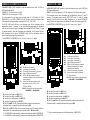
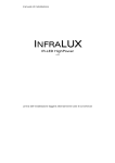
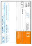
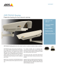
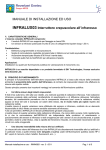
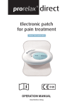
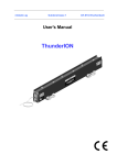
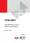
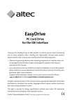
TECHNICAL DETAILS ACBOX3512 PSBOX35-00 AC INPUT (voltage range): OUTPUT: PSBOX75-TW INFRALUX Supply Unit 88-264 Vac 12Vdc-3A 12Vdc-3A OPERATING TEMPERATURE: 12Vdc-6A 2x 12Vdc-6A -20 °C ÷ + 70 °C HARNESSED VERSION*: NO CONNECTIONS: terminals YES REMOTE CONTROLLED STEERING: terminal blocks for cable connections NO YES POWER ADJUSTMENT: SEALED CABLE GLANDS: PSBOX75-00 DIMENSIONS (WxHxL) mm: 108x60x160 SAFETY STANDARDS: 1x PG11+4x PG7 135x75x200 SWITCHING SUPPLY UNIT provided in a die-cast aluminium box, with 1x PG11+2x PG7 sealed cable glands. Ideal for supplying n.1 IL200 It is also possible to use this unit to supply max.n.2 IL100 or n.2 IL150. In this case, make a parallel connection of the cables of the two illuminators to the switching terminals. For IL150 and IL200 only: the luminance level of the illuminator can be adjusted by using the T1 trimmer of the switching unit. If two illuminators are connected, the luminance level will be the same for both. (it decreases when moved ANTI-CLOCK wise). YES 1xPG11+2xPG7 ACBOX3512 (IP65) 135 x 90 x 270 UL60950-1, TUV EN 60950-1 approved EMC STANDARDS: EN55022 class B / EN 61000-3-2,3 / EN 61000-4-2,3,4,5,6,8,11 / ENV50204 / EN61000-6-2 (EN50082-2) (35-150W) ILLUMINATORS: IL200 IL200 IL300 IL400 Also for max: 2x IL100 2x IL150 2x IL100 2x IL150 2x IL200 2x IL300 WARNING! Please follow the right cable codes: + RED WIRE / ― BLACK WIRE If necessary, unscrew here in order to remove the supply unit All INFRALUX illuminators are protected against reversed polarity. In case the connection wires IN 230Vac (88-264Vac) * Harnessed supply units make it possible to use a steering board that can turn the illuminator T1, trimmer are reversed, a red signalling LED which can be seen through the front cover, will automatically flash. ON and OFF through a remote control. Both in case of automatic switch on through the illuminator photocell, and in case of remote INPUT, an OUTPUT is always available. Another option is a pre-harnessed supply unit, provided in a sealed box with pre-installed cable glands. PLEASE NOTE that standard switching supply units without sealed boxes are also available on request. 12Vdc Illuminator supply + RED WIRE / ― BLACK WIRE PG7 for illuminator/s VIA TURATI, 48 – 20090 TREZZANO S/N (MI) ITALY TEL: +39 02 45708686 – FAX: +39 02 45708694 WWW.SERINN.IT - [email protected] PG11 for the main supply For pole mounting, please use the following option: ACBOX3512-PM PSBOX35-00/PSBOX75-00 (IP65) PSBOX75-TW (IP65) HARNESSED SUPPLY UNIT provided in a die-cast aluminium box, with 1x PG11+4x PG7 sealed cable glands. PSBOX35-00, for the supply of n.1 IL200 PSBOX75-00, for the supply of n.1 IL300 It is also possible to use these units to supply max n.2 IL100 and/or n.2 IL150 (PSBOX35-00) or n.2 IL200 (PSBOX75-00). In this case, connect the cables of both illuminators to the corresponding terminals (ILL1 to M2 - ILL2 to M3). For IL150, IL200 and IL300 only: the luminance level of the illuminator can be adjusted by using a T1 trimmer. If two illuminators are connected, the luminance level will be the same for both (it decreases when moved ANTI-CLOCK wise). In case of remote steering*, when two illuminators are connected, the M4 control will turn both illuminators on; in case of AUTOMATIC switch, the first illuminator which is turned on will supply the output signal to M5. HARNESSED SUPPLY UNIT provided in a die-cast aluminium box, with 1x PG11+4x PG7 sealed cable glands. PSBOX75-TW, for the supply of n.1 IL400 (made of n.2 IL300 laid side by side). The luminance level of each illuminator can be adjusted by using a T1 and T2 trimmer (it decreases when moved ANTI-CLOCK wise). In case of remote steering*, the M4 control will turn both illuminators on; in case of AUTOMATIC switch, the first illuminator which is turned on will supply the output signal to M5. * see PHOTOCELL ADJUSTMENT on the INFRALUX USER MANUAL, * see PHOTOCELL ADJUSTMENT on the INFRALUX USER MANUAL, page 6 T2 T1 page 6 T1 M1 M2 M3 M4 M5 M1 M2 M3 M4 M5 T1 230Vac input (88-264Vac) 12Vdc supply for illuminator 1 12Vdc supply for illuminator 2 (if present) INput: NC/NO remote control* OUTput: NC/NO* automatic controlled (illuminator photocell) or M4 remote controlled output switching trimmer for illuminator luminance level adjustment (for IL150, IL200, IL300). * (NC=on, NO=off) WARNING! Please follow the right cable codes: + RED WIRE / ― BLACK WIRE L2, on when the supply is on M2 (ILL.1) L3, on when the supply is on M3 (ILL.2) L4 on when the remote control is on M4 (IN) L5, on when the switching is on M5 (OUT) J2 (for M2) and J3 (for M3), generally connected; please remove when the illuminator switch is remotely controlled with input on M4 R2 (for M2) and R3 (for M3), cut the terminal/s when only IL100 and/or IL150 are connected to the corresponding output terminal block/s (M2 and/or M3) For PSBOX35-00 pole mounting, please use the following option: ACBOX35-PM For PSBOX75-00 pole mounting, please use the following option: ACBOX75-PM T1 T2 230Vac input (88-264Vac) 12Vdc supply for illuminator 1 12Vdc supply for illuminator 2 INput: NC/NO remote control* OUTput: NC/NO* automatic controlled (illuminator photocell) or M4 remote controlled output switching trimmer for illuminator 1 adjustment trimmer for illuminator 2 adjustment * (NC=on, NO=off) WARNING! Please follow the right cable codes: + RED WIRE / ― BLACK WIRE L2, on when the supply is on M2 (ILL.1) L3, on when the supply is on M3 (ILL.2) L4 on when the remote control is on M4 (IN) L5, on when the switching is on M5 (OUT) J2 (for M2) and J3 (for M3), generally connected; please remove when the illuminator switch is remotely controlled with input on M4 For pole mounting, please use the following option: ACBOX75-PM